Procedure 13-2: Replace Alcatel-Lucent 1665 DMX standard shelf
 Overview
Use this procedure to replace the Alcatel-Lucent 1665 Data Multiplexerstandard shelf (C848540464). The standard shelf has a separate fan shelf. The High Capacity shelf has an integrated fan shelf.
Note that the Standard Shelf is Discontinued Availability effective 6/30/04.
Important!
It is assumed that the Alcatel-Lucent 1665 DMX is out of service. Power to the shelf will be removed in this procedure.
 Required equipment
Important!
A standard Alcatel-Lucent 1665 DMX shelf can be replaced with either a Standard or High Capacity Alcatel-Lucent 1665 DMX shelf.
The following equipment may be required:
-
Replacement Alcatel-Lucent 1665 DMX shelf (Refer to Engineering Drawing ED8C871-10 for a complete list of required cables.)
- If a High Capacity shelf is replacing a Standard shelf the following circuit packs and cables may be required in addition to the shelf
-
If high-density 56DS1/E1 circuit packs (LNW8) are being installed, additional DS1 cabling is required (same as the 28DS1/28DS1PM [LNW6/7]).
-
If high-density 48DS3/EC1 circuit packs (LNW19) are being installed, double- density DS3 cabling is required. The high density circuit packs cannot use the same cables as the 12DS3/EC1 (LNW16) circuit packs.
-
-
Personal Computer (PC) with WaveStar® CIT software installed
-
Alcatel-Lucent 1665 Data Multiplexer (DMX) Installation Manual, 365-372-304
If sync cables with molded DB-9 connectors are installed, then two sync cables as follows:
|
Cable Assembly # |
Cable Length (feet) |
|---|---|
|
848839619 |
50 |
|
848839627 |
100 |
|
848839635 |
150 |
|
848839643 |
250 |
|
848839650 |
450 |
Miscellaneous discrete cables as follows:
|
Cable Assembly # |
Cable Length (feet) |
|---|---|
|
848839569 |
50 |
|
848839577 |
100 |
|
848839585 |
150 |
|
848839593 |
250 |
|
848839601 |
350 |
 Before you begin
Prior to performing this procedure:
-
Refer to Before you begin in this chapter
-
Refer to Laser safety and Electrostatic discharge in Chapter 1, Safety.
-
Verify that the Alcatel-Lucent 1665 DMX shelf is out of service.
Steps
Complete the following steps to replace a Alcatel-Lucent 1665 DMX shelf.
1 |
Remove power to the Alcatel-Lucent 1665 DMX shelf by operating the circuit breakers to the OFF position at the Battery Distribution Fuse Bay (BDFB) in the central office or removing the fuses at the BDFB. Important! Remove power for both A and B feeders to the shelf. Result: Both PWR (A) and PWR (B) LEDs on the front of the shelf extinguish. Reference: Refer to the user documentation for your BDFB for more information. | ||
2 |
Disconnect the A and B power connectors from the left and right sides of the Alcatel-Lucent 1665 DMX shelf. | ||
3 |
Using a voltmeter, measure the voltage on the power cable connectors (looking towards the BDFB) between BAT A and BAT A RTN (red cable). Result: Voltmeter indicates no voltage. | ||
4 |
Using a voltmeter, measure the voltage on the power cable connectors (looking towards the shelf's backplane) between BAT B and BAT B RTN (blue cable). Result: Voltmeter indicates no voltage. | ||
5 |
On the backplane, label all cables connecting to the Alcatel-Lucent 1665 DMX shelf. These include: | ||
6 |
Remove all cables from the Alcatel-Lucent 1665 DMX shelf backplane. It may be necessary to untie the cables from the cable tie bar. Important! It is not necessary to disconnect the power cables on the backplane connectors (P15 and P14); they are internal to the shelf that is being removed. | ||
7 |
On the front of the Alcatel-Lucent 1665 DMX shelf, label all cables connecting to circuit packs. These include:
| ||
8 |
Remove all cables from circuit packs in the Alcatel-Lucent 1665 DMX shelf. | ||
9 |
Place protective dust covers on fiber connections (fibers and circuit packs). | ||
10 |
Note the position of each circuit pack (Function slot number or Growth slot) for reference when installing the new shelf. | ||
11 |
Carefully remove the fibers from the Alcatel-Lucent 1665 DMX shelf fiber tray. | ||
12 |
Disengage and remove each circuit pack and place each in an ESD protective bag. | ||
13 |
Unscrew the mounting screws that attach the Alcatel-Lucent 1665 DMX shelf to the bay frame and remove the shelf. If your replacement shelf is a Alcatel-Lucent 1665 DMX High Capacity shelf, you must also remove the fan shelf above the standard shelf. Important! Do not disturb cables associated with other Alcatel-Lucent 1665 Data Multiplexer shelves in the bay or equipment in adjacent bays. | ||
14 |
Inspect the replacement Alcatel-Lucent 1665 DMX shelf for visible damage including bent or touching backplane pins. | ||
15 |
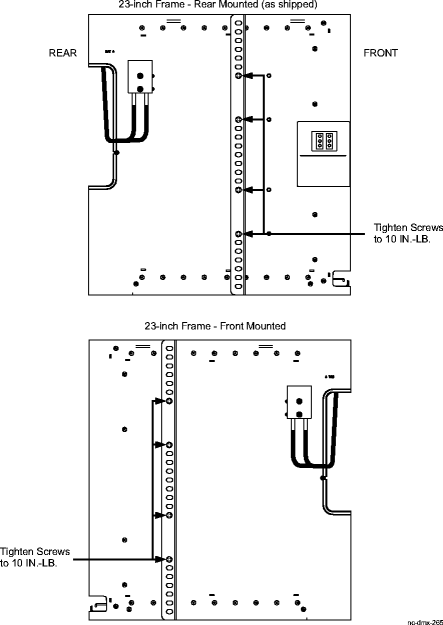
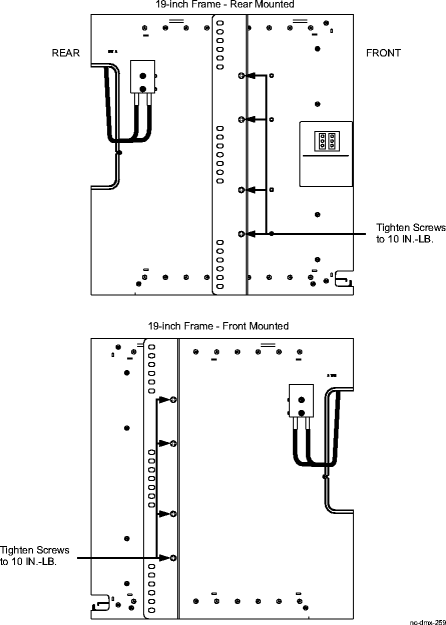
Determine the mounting configuration for the Alcatel-Lucent 1665 DMX shelf: Important! The Alcatel-Lucent 1665 DMX shelf is shipped with the mounting brackets positioned for mounting to the rear of a 23-inch wide network bay frame. The Alcatel-Lucent 1665 DMX shelf mounting brackets may have to be repositioned and remounted, depending on the frame type and mounting position (front or rear). | ||
16 |
If necessary, reposition the shelf mounting brackets accordingly. For 23-inch frame, front or rear mounting, refer to Figure 13-3, Alcatel-Lucent 1665 DMX mounting bracket positions - 23-inch frame. For 19-inch frame, front or rear mounting, refer to Figure 13-4, Alcatel-Lucent 1665 DMX mounting bracket positions - 19-inch frame. Figure 13-3: Alcatel-Lucent 1665 DMX mounting bracket positions - 23-inch frame
Figure 13-4: Alcatel-Lucent 1665 DMX mounting bracket positions - 19-inch frame | ||
17 |
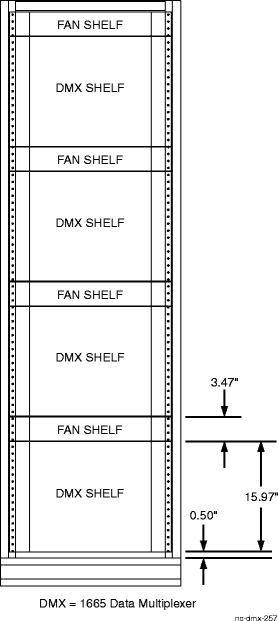
Determine the position that the Alcatel-Lucent 1665 DMX shelf will be mounted. Figure 13-5, Typical Alcatel-Lucent 1665 DMX standard shelf bay mounting arrangements shows the recommended mounting positions for a standard shelves. The Alcatel-Lucent 1665 DMX High Capacity shelf has an integrated fan shelf. Figure 13-9, Typical Alcatel-Lucent 1665 DMX High Capacity shelf bay mounting arrangements shows the recommended mounting positions for a high capacity shelves. Figure 13-5: Typical Alcatel-Lucent 1665 DMX standard shelf bay mounting arrangements | ||
18 |
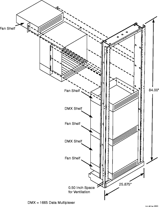
Position the Alcatel-Lucent 1665 DMX replacement shelf in the frame and secure the shelf to the frame using the thread-forming screws included with the shelf (3 screws per side). Tighten the screws to 21 in.-lb. (minimum)/30 in.-lb. (maximum) Figure 13-6, Alcatel-Lucent 1665 DMX shelf mounted to the rear of a 23-inch frame shows the Alcatel-Lucent 1665 DMX shelf being mounted to the rear of a 23-inch frame in a fully equipped Alcatel-Lucent 1665 DMX bay. The fan shelf may or may not be replaced while replacing the shelf. Important! Be sure to mount the shelf using the thread-forming screws provided with the shelf to ensure a solid ground connection from the bay to the shelf. Figure 13-6: Alcatel-Lucent 1665 DMX shelf mounted to the rear of a 23-inch frame | ||
19 |
Verify with an ohmmeter that the Alcatel-Lucent 1665 DMX shelf is grounded to the bay frame. Measure between the Alcatel-Lucent 1665 DMX shelf mounting bracket and the office ground lug on the bay frame. Result: The ohmmeter reads less than 1 ohm. | ||
20 |
Ensure that both 20-ampere circuit breakers on the Alcatel-Lucent 1665 DMX shelf to the OFF position. Important! A small flat-bladed screwdriver or other similar type tool is required to operate the circuit breakers to the OFF position. | ||
21 |
Reconnect the A and B power connectors to the left and right sides of the Alcatel-Lucent 1665 DMX shelf. | ||
22 |
At the rear of the shelf, reconnect all cables based on the labels placed on them when they were removed. If your replacement shelf is a Alcatel-Lucent 1665 DMX High Capacity shelf with high density circuit packs, you must also install additional DS1 cables and/or replace existing DS3 cables with double- density DS3 cabling. | ||
23 |
Restore power to the Alcatel-Lucent 1665 DMX shelf by operating the circuit breakers to the ON position at the Battery Distribution Feeder Bay (BDFB) or replacing the fuses at the BDFB. Important! Restore power for both the A and B feeders. | ||
24 |
Operate both 20-ampere circuit breakers on the Alcatel-Lucent 1665 DMX shelf to the ON position. These breakers are located on the front of the shelf. Result: The fans start running and both PWR (A) and PWR (B) LEDs on the front of the shelf light. | ||
25 |
Fully engage the SYSCTL circuit pack in the shelf. | ||
26 |
Fully engage the M1 and M2 circuit packs in the shelf. | ||
27 |
Starting at the left side of the shelf, fully engage each circuit pack in the shelf. Result: After approximately three minutes, all circuit packs have a lighted, green ACTIVE LED. | ||
28 |
Signal performance may be degraded if the connectors/adapters, fiber, and LBOs are not cleaned. Ensure all optical fiber connectors/adapters, fiber, and LBOs are properly cleaned. Clean and reconnect all optical fibers to the front of the optical circuit packs based on the fiber labels attached earlier and the circuit pack positions noted. Reference: Procedure 14-3: Clean optical fibers, dual LC adapters and LC lightguide buildouts (LBOs) | ||
29 |
Place loose fibers in the shelf fiber tray. | ||
30 |
Reconnect the LAN and CIT cables (if equipped) to the front of the SYSCTL circuit pack. | ||
31 |
Connect the WaveStar® CIT and log into the shelf. Reference: Procedure 14-2: Connect Personal Computer (PC) and establish WaveStar® CIT session | ||
32 |
From the System View window, click on Alarm List button and verify that there are no alarms, lockouts, loopbacks, or switches present. If required, refer to the appropriate trouble clearing procedures to clear any existing alarms. Reference: Alcatel-Lucent 1665 Data Multiplexer (DMX) Alarm Messages and Trouble Clearing Guide, 365-372-302 End of steps |