Procedure 12-6.6: Back out OC-12 UPSR to OC-48 UPSR upgrade at node with multirate circuit packs
Important!
This is not a stand-alone procedure. Perform this procedure only as directed by another procedure.
Steps
Important!
When optical fibers are disconnected during this procedure, inc. LOS, section DCC channel failed, and neighbor SYSCTL CP unavailable alarms are reported. The holdover mode active condition may also be reported depending on the provisioned system timing mode.
Complete the following steps to back out an OC-12 UPSR to OC-48 UPSR upgrade at an Alcatel-Lucent 1665 DMX node connected to the UPSR using multirate circuit packs in the Main/Function/Growth slots.
1 |
Determine the current status of the upgrade at the node.
| ||||||||
2 |
If required, verify the active/standby status of the OC-48 port on the multirate circuit pack in Main/Function/Growth slot 2 and perform manual switches to switch traffic away from an active circuit pack/port. Reference: Procedure 12-6.5: Verify active/standby status of circuit pack/port to be backed out | ||||||||
3 |
Select Configuration → Equipment and expand the circuit pack in Main/Function/Growth slot 2. Click on the required OC-48 port and Select to obtain the port parameters. Provision the port Signal Type parameter to OC-12 and click Apply. Result:
| ||||||||
4 |
Important! If the port is active for timing and/or transmission, disconnecting the optical fibers causes timing and/or transmission switches. Transmission hits (less than 60 ms) will occur for each separate protection switch. If required, disconnect the optical fibers from the single-rate OC-48 pluggable transmission module in Main/Function/Growth slot 2. Then replace the single-rate OC-48 pluggable transmission module in Main/Function/Growth slot 2 with the original OC-12 pluggable transmission module. Result: The original OC-12 pluggable transmission module in Main/Function/Growth slot 2 is tested and autoprovisioned. The unexpected or failed Pluggable Transmission Module alarm for Main/Function/Growth slot 2 clears, and the system reports an inc. OC12 LOS alarm for Main/Function/Growth slot 2. Alarms may also be reported at other nodes in the ring. Reference: Procedure 4-15: Install pluggable transmission modules | ||||||||
5 |
If required at both ends of the optical span to be upgraded, perform the following to connect the original OC-12 pluggable transmission module in Main/Function/Growth slot 2 and the required circuit pack/port at the opposite end of the original OC-12 optical span:
Result: The inc. OC12 LOS alarms clear. Transmission is now supported on the original OC-12 optical span. Reference: Procedure 14-4: Perform connection and verification of optical facility | ||||||||
6 |
Important! Perform this step only if the opposite end of the original optical span is an OC-12 port in a Function/Growth group and the Optical Synchronization Source is to be reprovisioned to the original OC-12 port. If required at the opposite end of the original optical span, select Configuration → Timing/Sync to reprovision the Optical Synchronization Source to the original OC-12 port on the OC-12 OLIU circuit pack in slot 2 of the Function/Growth group. Reference: Procedure 6-5: Network Element synchronization provisioning | ||||||||
7 |
If required, verify the active/standby status of the OC-48 port on the multirate circuit pack in Main/Function/Growth slot 1 and perform manual switches to switch traffic away from an active circuit pack/port. Reference: Procedure 12-6.5: Verify active/standby status of circuit pack/port to be backed out | ||||||||
8 |
Select Configuration → Equipment and expand the circuit pack in Main/Function/Growth slot 1. Click on the required OC-48 port and Select to obtain the port parameters. Provision the port Signal Type parameter to OC-12 and click Apply. Result:
| ||||||||
9 |
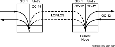
Important! Do not reconnect the optical fibers until instructed to do so. The optical fibers are reconnected after the circuit pack/port is backed out at each end of the optical span. If the port is active for timing and/or transmission, disconnecting the optical fibers causes timing and/or transmission switches. Transmission hits (less than 60 ms) will occur for each separate protection switch. If required, disconnect the optical fibers from the single-rate OC-48 pluggable transmission module in Main/Function/Growth slot 1. Then replace the single-rate OC-48 pluggable transmission module in Main/Function/Growth slot 1 with the original OC-12 pluggable transmission module. Result: The original OC-12 pluggable transmission module in Main/Function/Growth slot 1 is tested and autoprovisioned. The unexpected or failed Pluggable Transmission Module alarm for Main/Function/Growth slot 1 clears, and the system reports an inc. OC12 LOS alarm for Main/Function/Growth slot 1. Alarms may also be reported at other nodes in the ring. Reference: Procedure 4-15: Install pluggable transmission modules The following figure shows the state of the current node and the adjacent optical spans. Important! If the original OC-12 port in Main/Function/Growth slot 1 at the current node is equipped with a single-rate pluggable transmission module, inc. LOS alarms are reported. If the original OC-12 port in Main/Function/Growth slot 1 at the current node is equipped with a multirate pluggable transmission module, inc. LOF alarms are reported. 
STOP! To complete the upgrade, return to the procedure that directed you to perform this procedure. End of steps |