Procedure 4-15: Install pluggable transmission modules
 Privilege level
You must log in as a Privileged, General, Maintenance, or Reports Only user to complete this procedure.
Required equipment
Use only the following Alcatel-Lucent Approved Class 1 SFP/XFP transceivers.
|
Name/ Qualifier |
Pluggable Transmission Module Code/Comcode |
Description |
Compatible Circuit Packs |
|---|---|---|---|
|
EM1G//EMFE 1000BASE-T//100BASE-T |
BASE-T-C1 109565549 |
10 Mb/s, 100 Mb/s and GbE, Copper, SFP TRCVR |
LNW63 LNW64 LNW70/LNW170 LNW78 LNW87 |
|
OM155 1.3IR1 |
OC3IR1-I1 109453894 |
OC3 IR1, SM, 1310 nm, 15 km, SFP TRCVR |
LNW37 LNW45 LNW55 LNW82 LNW705 |
|
OM155 1.3LR1 |
OC3LR1-I1 109453886 |
OC3 LR1, SM, 1310 nm, 40 km, SFP TRCVR |
LNW37 LNW45 LNW55 LNW82 LNW705 |
|
OM155 1.3SR1 |
S155I2 109602599 |
OC-3 SR-1/STM-1, SM, 1310 nm, 2 km, SFP TRCVR |
LNW37 LNW45 LNW55 LNW82 LNW705 |
|
OM155//OM622 //2.5G 1.3IR1//1.3IR1// 1.3IR1 |
OC3X12X48-IR1-I1 109708131 |
OC3/STM1/OC12/ STM4/OC48/STM16, 1310nm, 15 km, SFP TRCVR |
LNW55 LNW82 |
|
OM155//OM622// 2.5G 1.3LR1//1.3LR1// 1.3LR1 |
OC3X12X48-LR1-I1 109708149 |
OC3/STM1/OC12/ STM4/OC48/STM16, 1310nm, 40km, 15 km, SFP TRCVR |
LNW55 LNW82 |
|
OM622 1.3IR1 |
OC12IR1-I1 109453902 |
OC12 IR1, SM, 1310 nm, 15 km, SFP TRCVR |
LNW49 LNW55 LNW82 LNW203 LNW705 |
|
OM622 1.3LR1 |
OC12LR1-I1 109467522 |
OC12 LR1, SM, 1310 nm, 40 km, SFP TRCVR |
LNW49 LNW55 LNW82 LNW203 LNW705 |
|
OM622 1.5LR2 |
OC12LR2-I1 109604447 |
OC12 LR2, SM, 1550 nm, 80 km, SFP TRCVR |
LNW49 LNW55 LNW82 LNW203 LNW705 |
|
OM155//OM622/ CWDM-LR |
S622C47EL 109664086 |
OC-3/STM-1 or OC-12/STM-4 CWDM, 1471 nm, SFP TRCVR |
LNW37 LNW45 LNW49 LNW55 LNW82 LNW705 |
|
OM155//OM622/ CWDM-LR |
S622C49EL 109664094 |
OC-3/STM-1 or OC-12/STM-4 CWDM, 1491 nm, SFP TRCVR |
LNW37 LNW45 LNW49 LNW55 LNW82 LNW705 |
|
OM155//OM622/ CWDM-LR |
S622C51EL 109664102 |
OC-3/STM-1 or OC-12/STM-4 CWDM, 1511 nm, SFP TRCVR |
LNW37 LNW45 LNW49 LNW55 LNW82 LNW705 |
|
OM155//OM622/ CWDM-LR |
S622C53EL 109664110 |
OC-3/STM-1 or OC-12/STM-4 CWDM, 1531 nm, SFP TRCVR |
LNW37 LNW45 LNW49 LNW55 LNW82 LNW705 |
|
OM155//OM622/ CWDM-LR |
S622C55EL 109664128 |
OC-3/STM-1 or OC-12/STM-4 CWDM, 1551 nm, SFP TRCVR |
LNW37 LNW45 LNW49 LNW55 LNW82 LNW705 |
|
OM155//OM622/ CWDM-LR |
S622C57EL 109664136 |
OC-3/STM-1 or OC-12/STM-4 CWDM, 1571 nm, SFP TRCVR |
LNW37 LNW45 LNW49 LNW55 LNW82 LNW705 |
|
OM155//OM622/ CWDM-LR |
S622C59EL 109664144 |
OC-3/STM-1 or OC-12/STM-4 CWDM, 1591 nm, SFP TRCVR |
LNW37 LNW45 LNW49 LNW55 LNW82 LNW705 |
|
OM155//OM622/ CWDM-LR |
S622C61EL 109664151 |
OC-3/STM-1 or OC-12/STM-4 CWDM, 1611 nm, SFP TRCVR |
LNW37 LNW45 LNW49 LNW55 LNW82 LNW705 |
|
OM1G 1000BASE-ZX |
1000BASE-ZX-I1 109541862 |
GbE SM 1550 nm 1000BASE-ZX SFP TRCVR |
LNW63 LNW64 LNW70/LNW170 LNW78 LNW87 |
|
OM1G//OMFC 1000BASE-LX//100/200-SM-LL-L-I 1 |
GE-1X2XFC-LX-C1 109527804 |
GbE SM 1310 nm 1XFC/2XFC 1000BASE-LX SFP TRCVR |
LNW64 LNW70/LNW170 LNW73/73C LNW78 LNW87 |
|
OM1G//OMFC 1000BASE-LX//100/200-SM-LL-L-I |
GE-1X2XFC-LX-I1 109568782 |
GbE SM 1310 nm 1XFC/2XFC 1000BASE-LX SFP TRCVR |
LNW63 LNW64 LNW70/LNW170 LNW73/73C LNW78 LNW87 LNW705 |
|
OM1G//OMFC 1000BASE-SX//100/200-M5/M6-SN-S 1 |
GE-1X2XFC-SX-C1 109527796 |
GbE MM 850 nm 1XFC/2XFC 1000BASE-SX SFP TRCVR |
LNW64 LNW70/LNW170 LNW73/73C LNW78 LNW87 |
|
OM1G//OMFC 1000BASE-SX//100/200-M5/M6-SN-S |
GE-1X2XFC-SX-I1 109570606 |
GbE MM 850 nm 1XFC/2XFC 1000BASE-SX SFP TRCVR |
LNW63 LNW64 LNW70/LNW170 LNW73/73C LNW78 LNW87 LNW705 |
|
OM2.5G 1.3LR1 |
OC48LR1-I1 109493528 |
OC48 LR1, SM, 1310 nm, 40 km, SFP TRCVR |
LNW55 LNW62 LNW82 LNW202 LNW402 LNW504 LNW705 |
|
OM2.5G 1.5LR2 |
OC48LR2-I1 109504431 |
OC48 LR2, SM, 1550 nm, 80 km, SFP TRCVR |
LNW55 LNW62 LNW82 LNW202 LNW402 LNW504 LNW705 |
|
OM2.5G 1.3SR1 |
OC48SR1-I1 109564518 |
OC48 SR1, SM, 1310 nm, 2 km, SFP TRCVR |
LNW55 LNW62 LNW82 LNW202 LNW402 LNW705 |
|
OM2.5G 1.5LR2 |
S2D23C6 109610378 |
OC-48 /STM-16/OTU1 DWDM, 192.3 THz, 1558.983 nm, SFP TRCVR |
LNW55 LNW62 LNW82 LNW202 LNW402 LNW504 |
|
OM2.5G 1.5LR2 |
S2D25C6 109610394 |
OC-48 /STM-16/OTU1 DWDM, 192.5 THz, 1557.363 nm, SFP TRCVR |
LNW55 LNW62 LNW82 LNW202 LNW402 LNW504 |
|
OM2.5G 1.5LR2 |
S2D27C6 109610410 |
OC-48 /STM-16/OTU1 DWDM, 192.7 THz, 1555.747 nm, SFP TRCVR |
LNW55 LNW62 LNW82 LNW202 LNW402 LNW504 |
|
OM2.5G 1.5LR2 |
S2D31C6 109610451 |
OC-48 /STM-16/OTU1 DWDM, 193.1 THz, 1552.524 nm, SFP TRCVR |
LNW55 LNW62 LNW82 LNW202 LNW402 LNW504 |
|
OM2.5G 1.5LR2 |
S2D33C6 109610477 |
OC-48 /STM-16/OTU1 DWDM, 193.3 THz, 1550.918 nm, SFP TRCVR |
LNW55 LNW62 LNW82 LNW202 LNW402 LNW504 |
|
OM2.5G 1.5LR2 |
S2D35C6 109610493 |
OC-48 /STM-16/OTU1 DWDM, 193.5 THz, 1549.315 nm, SFP TRCVR |
LNW55 LNW62 LNW82 LNW202 LNW402 LNW504 |
|
OM2.5G 1.5LR2 |
S2D37C6 109610519 |
OC-48 /STM-16/OTU1 DWDM, 193.7 THz, 1547.715 nm, SFP TRCVR |
LNW55 LNW62 LNW82 LNW202 LNW402 LNW504 |
|
OM2.5G 1.5LR2 |
S2D45C6 109610600 |
OC-48 /STM-16/OTU1 DWDM, 194.5 THz, 1541.349 nm, SFP TRCVR |
LNW55 LNW62 LNW82 LNW202 LNW402 LNW504 |
|
OM2.5G 1.5LR2 |
S2D47C6 109610626 |
OC-48 /STM-16/OTU1 DWDM, 194.7 THz, 1539.766 nm, SFP TRCVR |
LNW55 LNW62 LNW82 LNW202 LNW402 LNW504 |
|
OM2.5G 1.5LR2 |
S2D49C6 109610642 |
OC-48 /STM-16/OTU1 DWDM, 194.9 THz, 1538.186 nm, SFP TRCVR |
LNW55 LNW62 LNW82 LNW202 LNW402 LNW504 |
|
OM2.5G 1.5LR2 |
S2D53C6 109610691 |
OC-48 /STM-16/OTU1 DWDM, 195.3 THz, 1535.036 nm, SFP TRCVR |
LNW55 LNW62 LNW82 LNW202 LNW402 LNW504 |
|
OM2.5G 1.5LR2 |
S2D55C6 109610717 |
OC-48 /STM-16/OTU1 DWDM, 195.5 THz, 1533.465 nm, SFP TRCVR |
LNW55 LNW62 LNW82 LNW202 LNW402 LNW504 |
|
OM2.5G 1.5LR2 |
S2D59C6 109610766 |
OC-48 /STM-16/OTU1 DWDM, 195.9 THz, 1530.334 nm, SFP TRCVR |
LNW55 LNW62 LNW82 LNW202 LNW402 LNW504 |
|
OM2.5G/SL-16.2 |
S2G7C47LI 1AB402160002 |
OC48/STM16 CWDM 1471 nm, SFP TRCVR S-C8L1-1D2 : S-C8L1-1D5 |
LNW55 LNW62 LNW82 LNW202 LNW402 LNW504 |
|
OM2.5G/SL-16.2 |
S2G7C49LI 1AB402160003 |
OC48/STM16CWDM 1491 nm, SFP TRCVR S-C8L1-1D2 : S-C8L1-1D5 |
LNW55 LNW62 LNW82 LNW202 LNW402 LNW504 |
|
OM2.5G/SL-16.2 |
S2G7C51LI 1AB402160004 |
OC48/STM16 CWDM 1511 nm, SFP TRCVR S-C8L1-1D2 : S-C8L1-1D5 |
LNW55 LNW62 LNW82 LNW202 LNW402 LNW504 |
|
OM2.5G/SL-16.2 |
S2G7C53LI 1AB402160005 |
OC48/STM16 CWDM 1531 nm, SFP TRCVR S-C8L1-1D2 : S-C8L1-1D5 |
LNW55 LNW62 LNW82 LNW202 LNW402 LNW504 |
|
OM2.5G/SL-16.2 |
S2G7C55LI 1AB402160006 |
OC48/STM16 CWDM 1551 nm, SFP TRCVR S-C8L1-1D2 : S-C8L1-1D5 |
LNW55 LNW62 LNW82 LNW202 LNW402 LNW504 |
|
OM2.5G/SL-16.2 |
S2G7C57LI 1AB402160007 |
OC48/STM16CWDM 1571 nm, SFP TRCVR S-C8L1-1D2 : S-C8L1-1D5 |
LNW55 LNW62 LNW82 LNW202 LNW402 LNW504 |
|
OM2.5G/SL-16.2 |
S2G7C59LI 1AB402160008 |
OC48/STM16 CWDM 1591 nm, SFP TRCVR S-C8L1-1D2 : S-C8L1-1D5 |
LNW55 LNW62 LNW82 LNW202 LNW402 LNW504 |
|
OM2.5G/SL-16.2 |
S2G7C61LI 1AB402160009 |
OC48/STM16 CWDM 1611 nm, SFP TRCVR S-C8L1-1D2 : S-C8L1-1D5 |
LNW55 LNW62 LNW82 LNW202 LNW402 LNW504 |
|
OM10G 1.5IR2 (S-64.2b) |
OC192IR2-C1 109537563 |
OC192 IR2, SM, 1550 nm, 40 km, XFP TRCVR |
LNW59 LNW502 LNW504 LNW603 LNW705 |
|
OM10G 1.5IR2 (S-64.2b) |
OC192IR2-I1 109586479 |
OC192 IR2, SM, 1550 nm, 40 km, XFP TRCVR |
LNW59 LNW705 |
|
OM10G 1.5LR2 (P1L1-2D2) |
OC192LR2-C1 109537555 |
OC192 LR2, SM, 1550 nm, 80 km, XFP TRCVR |
LNW59 LNW502 LNW504 LNW603 LNW705 |
|
OM10G 1.3SR1 (I-64.1) |
OC192SR1-C1 109537902 |
OC192 SR1, SM, 1310 nm, 2 km, XFP TRCVR |
LNW59 LNW502 LNW504 LNW603 LNW705 |
|
OM10G DWDMLR (DW100U- 2AxC(F)) |
X10G21C5 109615005 |
OC-192/STM-64/OTU2 DWDM, 192.1 THz, 1560.606 nm, XFP TRCVR |
LNW59 LNW502 LNW603 LNW705 |
|
OM10G DWDMLR (DW100U- 2AxC(F)) |
X10G22C5 109615013 |
OC-192/STM-64/ OTU2 DWDM, 192.2 THz, 1559.794 nm, XFP TRCVR |
LNW59 LNW502 LNW603 LNW705 |
|
OM10G DWDMLR (DW100U- 2AxC(F)) |
X10G23C5 109615021 |
OC-192/STM-64/ OTU2 DWDM, 192.3 THz, 1558.983 nm, XFP TRCVR |
LNW59 LNW502 LNW603 LNW705 |
|
OM10G DWDMLR (DW100U- 2AxC(F)) |
X10G24C5 109615039 |
OC-192/STM-64/ OTU2 DWDM, 192.4 THz, 1558.173 nm, XFP TRCVR |
LNW59 LNW502 LNW603 LNW705 |
|
OM10G DWDMLR (DW100U- 2AxC(F)) |
X10G25C5 109615047 |
OC-192/STM-64/ OTU2 DWDM, 192.5 THz, 1557.363 nm, XFP TRCVR |
LNW59 LNW502 LNW603 LNW705 |
|
OM10G DWDMLR (DW100U- 2AxC(F)) |
X10G26C5 109615054 |
OC-192/STM-64/ OTU2 DWDM, 192.6 THz, 1556.555 nm, XFP TRCVR |
LNW59 LNW502 LNW603 LNW705 |
|
OM10G DWDMLR (DW100U- 2AxC(F)) |
X10G27C5 109615062 |
OC-192/STM-64/ OTU2 DWDM, 192.7 THz, 1555.747 nm, XFP TRCVR |
LNW59 LNW502 LNW603 LNW705 |
|
OM10G DWDMLR (DW100U- 2AxC(F)) |
X10G28C5 109615070 |
OC-192/STM-64/ OTU2 DWDM, 192.8 THz, 1554.940 nm, XFP TRCVR |
LNW59 LNW502 LNW603 LNW705 |
|
OM10G DWDMLR (DW100U- 2AxC(F)) |
X10G31C5 109615104 |
OC-192/STM-64/ OTU2 DWDM, 193.1 THz, 1552.524 nm, XFP TRCVR |
LNW59 LNW502 LNW504 LNW603 LNW705 |
|
OM10G DWDMLR (DW100U- 2AxC(F)) |
X10G33C5 109615120 |
OC-192/STM-64/ OTU2 DWDM, 193.3 THz, 1550.918 nm, XFP TRCVR |
LNW59 LNW502 LNW504 LNW603 LNW705 |
|
OM10G DWDMLR (DW100U- 2AxC(F)) |
X10G35C5 109615146 |
OC-192/STM-64/ OTU2 DWDM, 193.5 THz, 1549.315 nm, XFP TRCVR |
LNW59 LNW502 LNW504 LNW603 LNW705 |
|
OM10G DWDMLR (DW100U- 2AxC(F)) |
X10G37C5 109615161 |
OC-192/STM-64/ OTU2 DWDM, 193.7 THz, 1547.715 nm, XFP TRCVR |
LNW59 LNW502 LNW504 LNW603 LNW705 |
|
OM10G DWDMLR (DW100U- 2AxC(F)) |
X10G45C5 109615245 |
OC-192/STM-64/ OTU2 DWDM, 194.5 THz, 1541.349 nm, XFP TRCVR |
LNW59 LNW502 LNW504 LNW603 LNW705 |
|
OM10G DWDMLR (DW100U- 2AxC(F)) |
X10G47C5 109615260 |
OC-192/STM-64/ OTU2 DWDM, 194.7 THz, 1539.766 nm, XFP TRCVR |
LNW59 LNW502 LNW504 LNW603 LNW705 |
|
OM10G DWDMLR (DW100U- 2AxC(F)) |
X10G49C5 109615286 |
OC-192/STM-64/ OTU2 DWDM, 194.9 THz, 1538.186 nm, XFP TRCVR |
LNW59 LNW502 LNW504 LNW603 LNW705 |
|
OM10G DWDMLR (DW100U- 2AxC(F)) |
X10G52C5 109615310 |
OC-192/STM-64/ OTU2 DWDM, 195.2 THz, 1535.822 nm, XFP TRCVR |
LNW59 LNW502 LNW603 LNW705 |
|
OM10G DWDMLR (DW100U- 2AxC(F)) |
X10G53C5 109615328 |
OC-192/STM-64/ OTU2 DWDM, 195.3 THz, 1535.036 nm, XFP TRCVR |
LNW59 LNW502 LNW603 LNW705 |
|
OM10G DWDMLR (DW100U- 2AxC(F)) |
X10G54C5 109615336 |
OC-192/STM-64/ OTU2 DWDM, 195.4 THz, 1534.250 nm, XFP TRCVR |
LNW59 LNW502 LNW603 LNW705 |
|
OM10G DWDMLR (DW100U- 2AxC(F)) |
X10G55C5 109615344 |
OC-192/STM-64/ OTU2 DWDM, 195.5 THz, 1533.465 nm, XFP TRCVR |
LNW59 LNW502 LNW603 LNW705 |
|
OM10G DWDMLR (DW100U- 2AxC(F)) |
X10G56C5 109615351 |
OC-192/STM-64/ OTU2 DWDM, 195.6 THz, 1532.681 nm, XFP TRCVR |
LNW59 LNW502 LNW603 LNW705 |
|
OM10G DWDMLR (DW100U- 2AxC(F)) |
X10G57C5 109615369 |
OC-192/STM-64/ OTU2 DWDM, 195.7 THz, 1531.898 nm, XFP TRCVR |
LNW59 LNW502 LNW603 LNW705 |
|
OM10G DWDMLR (DW100U- 2AxC(F)) |
X10G58C5 109615377 |
OC-192/STM-64/ OTU2 DWDM, 195.8 THz, 1531.116 nm, XFP TRCVR |
LNW59 LNW502 LNW603 LNW705 |
|
OM10G DWDMLR (DW100U- 2AxC(F)) |
X10G59C5 109615385 |
OC-192/STM-64/ OTU2 DWDM, 195.9 THz, 1530.334 nm, XFP TRCVR |
LNW59 LNW502 LNW603 LNW705 |
|
OMESCON MMF |
ESCON-MM-I1 109523886 |
ESCON MM, 1310 nm SFP TRCVR |
LNW73/73C |
|
OMFE 100BASE-LX-SM |
100BASE-LX-I1 109527812 |
100 Mb/s optical Fast Ethernet SFP TRCVR |
LNW70/LNW170 LNW74 LNW78 LNW87 |
|
OMFE 100BASE-FX |
100BASE-FX-I1 109703140 |
100 Mb/s optical Fast Ethernet SFP TRCVR |
LNW70/LNW170 LNW74 LNW78 LNW87 |
|
OMFE 100BASE-ZX |
100BASE-ZX-I1 109703157 |
100 Mb/s optical Fast Ethernet SFP TRCVR |
LNW74 LNW87 LNW70/170 |
Notes:
Refer to the Alcatel-Lucent 1665 Data Multiplexer (DMX) Installation Manual, 365-372-304, as required, when removing and/or installing pluggable transmission modules.
Ethernet port configurations (LNW63, LNW64, LNW70/LNW170, LNW74, and LNW78 circuit packs)
The LNW63, LNW64, LNW70/LNW170, LNW74, and LNW78 circuit packs support the following provisionable Ethernet port configurations. The Ethernet port configurations on LNW87 circuit packs may be provisioned independently.
|
Ethernet port mode parameter setting |
Ethernet Circuit Packs | ||||
|---|---|---|---|---|---|
|
LNW63 |
LNW64 |
LNW70/ LNW170 |
LNW74 |
LNW78 | |
|
GX_FX |
— |
— |
Ports 1-4: optical GbE Ports 5-8: optical FE |
— |
Ports 1-2: optical GbE Ports 5-8: optical FE |
|
GT_FX |
— |
— |
Ports 1-4: electrical GbE Ports 5-8: optical FE |
— |
Ports 1-2: electrical GbE Ports 5-8: optical FE |
|
FT_FX |
— |
— |
Ports 1-4: electrical FE Ports 5-8: optical FE |
Electrical FE Backplane Ports 1-16: Enabled Ports 17-24: optical FE |
— |
|
FX |
— |
— |
— |
Electrical FE Backplane Ports 1-16: Disabled Ports 17-24: optical FE |
— |
|
GX_FT |
— |
— |
Ports 1-4: optical GbE Ports 5-8: electrical FE |
— |
Ports 1-2: optical GbE Ports 5-8: electrical FE |
|
GT_FT |
— |
— |
Ports 1-4: electrical GbE Ports 5-8: electrical FE |
— |
Ports 1-2: electrical GbE Ports 5-8: electrical FE |
|
FT |
— |
— |
Ports 1-8: electrical FE |
— |
— |
|
GX |
Ports 1-4: optical GbE |
Ports 1-8: optical GbE |
— |
— |
— |
|
GT |
Ports 1-4: electrical GbE |
Ports 1-8: electrical GbE |
— |
— |
— |
|
GT_GX |
— |
Ports 1-4: electrical GbE Ports 5-8: optical GbE |
— |
— |
— |
Ethernet port configurations (LNW87 circuit packs)
The LNW87 circuit pack supports the following provisionable Ethernet port configurations. The Ethernet port configuration may be provisioned independently for each port.
|
Ethernet port mode parameter setting |
Description |
|---|---|
|
GX |
Ports 1-4 |
|
GT | |
|
FX | |
|
FT |
LNW55 OC3/OC12/OC48 OLIU circuit pack port configurations
The LNW55 OC3/OC12/OC48 OLIU circuit pack is a 12-port, SFP-based, multirate (OC-3, OC-12, OC-48), low-speed optical circuit pack. The LNW55 OLIU circuit pack supports a maximum of either 12 OC-3 ports, or 12 OC-12 ports, or 4 OC-48 ports.
Mixing port optical rates is supported with the following restrictions.
-
OC-48 interfaces are only supported on ports 1, 4, 7, and 10.
-
When the Signal Type parameter is provisioned to OC-48 for port 1, 4, 7, or 10, then the next two adjacent ports are unavailable for use. For example, if the Signal Type parameter for port 1 is provisioned to OC-48, then ports 2 and 3 are unavailable for use (STNA - Signal Type Not Available).
Before installing a pluggable transmission module in an LNW55 OLIU circuit pack, the port Signal Type parameter must be provisioned to match the pluggable transmission module. If the port Signal Type parameter is STNA (default value) and a pluggable transmission module is installed, the system reports an unexpected or failed Pluggable Transmission Module alarm.
LNW82 OC3/OC12/OC48 OLIU circuit pack port configurations
The LNW82 OC3/OC12/OC48 OLIU circuit pack is an 8-port, SFP-based, multirate (OC-3, OC-12, OC-48), high-speed optical circuit pack. The LNW82 OLIU circuit pack supports a maximum of either 8 OC-3 ports, or 8 OC-12 ports, or 2 OC-48 ports.
Mixing port optical rates is supported with the following restrictions.
-
When the Signal Type parameter is provisioned to OC-48 for port 1 or 5, then the next three adjacent ports are unavailable for use. For example, if the Signal Type parameter for port 1 is provisioned to OC-48, then ports 2, 3, and 4 are unavailable for use (STNA - Signal Type Not Available).
Before installing a pluggable transmission module in an LNW82 OLIU circuit pack, the port Signal Type parameter must be provisioned to match the pluggable transmission module. If the port Signal Type parameter is STNA (default value) and a pluggable transmission module is installed, the system reports an unexpected or failed Pluggable Transmission Module alarm.
LNW504 OC-48/OC-192 OLIU circuit pack port configurations
The LNW504 is an 8-port, SFP/XFP-based, multirate (OC-48, OC-192) high-speed optical circuit pack. The LNW504 OLIU circuit pack supports a maximum of 4 OC-48 interfaces and 4 OC-192 interfaces with the following restrictions:
-
If port 4 is provisioned to OC-192 then ports 5-8 cannot be used (STNA). If port 4 is provisioned to STNA, then ports 5-8 are provisioned for OC–48.
Before installing a pluggable transmission module in an LNW504 OLIU circuit pack, the port Signal Type parameter must be provisioned to match the pluggable transmission module. If the port Signal Type parameter is STNA (default value) and a pluggable transmission module is installed, the system reports an unexpected or failed Pluggable Transmission Module alarm.
LNW705 10G Muxponder circuit pack client port configurations
The LNW705 10G Muxponder circuit pack supports a mix of 1GE, FC100, FICON, FC200, FICON_EXP, and/or OC3/12/48 client signals. The client signals are mapped into a single STS-192 and transmitted as an OTN OTU-2 signal.
Mixing client signals is supported with the following restrictions.
-
OC-48, FC200, FICON_EXP signals are only supported on client ports 1, 3, 5, and 7.
-
When the Signal Type parameter is provisioned to OC-48, FC200, FICON_EXP for client port 1, 3, 5, or 7, then the next adjacent client port is unavailable for use. For example, if the Signal Type parameter for client port 1 is provisioned to OC-48, then client port 2 is unavailable for use (STNA - Signal Type Not Available).
Before installing a pluggable transmission module in an LNW705 10G Muxponder circuit pack, the port Signal Type parameter must be provisioned to match the pluggable transmission module. If the port Signal Type parameter is STNA (default value) and a pluggable transmission module is installed, the system reports an unexpected or failed Pluggable Transmission Module alarm.
 Before you begin
Prior to performing this procedure:
-
Refer to Required equipment and Before you begin in this chapter.
-
Refer to Laser safety and Electrostatic discharge in Chapter 1, Safety.
-
Verify that the work instructions specify the required pluggable transmission module, circuit pack, and socket.
-
Ensure that the correct pluggable transmission module is available for installation.
Steps
Complete the following steps to install a pluggable transmission module in a circuit pack that has already been installed in the shelf.
1 |
Determine the circuit pack and socket being equipped with the pluggable transmission module. | ||||||||||
2 |
Important! Before installing a pluggable transmission module in an LNW55, LNW82, LNW504, or LNW705 (client ports only) circuit pack, the port Signal Type parameter must be provisioned to match the pluggable transmission module. If the LNW705 circuit pack OTU2 port is connected to a LNW785 circuit pack input, the expected frequency must be provisioned to match the LNW785 circuit pack channel frequency. If the port Signal Type parameter is STNA (default value) and a pluggable transmission module is installed, the system reports an unexpected or failed Pluggable Transmission Module alarm. If required, select Configuration → Equipment to access the required port and provision the port Signal Type parameter to match the pluggable transmission module. Reference:
| ||||||||||
3 |
Hold the connector/latch-end of the module in your left hand with the gold fingers facing you. The module should be positioned in manner similar to Figure 4-8, Pluggable transmission module with dust cover (Optical PTMs only). Figure 4-8: Pluggable transmission module with dust cover (Optical PTMs only)
Important! Do not remove the dust cover unless you are ready to connect cabling or if you need to clean the module. Dust covers (Optical PTMs only) There are a variety of different types of dust covers. Any of the following examples could be similar to the dust cover in your pluggable transmission module. Figure 4-9: Examples of dust covers | ||||||||||
4 |
Referring to the figure below, determine the type of latching mechanism on the pluggable transmission module you have. 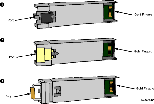
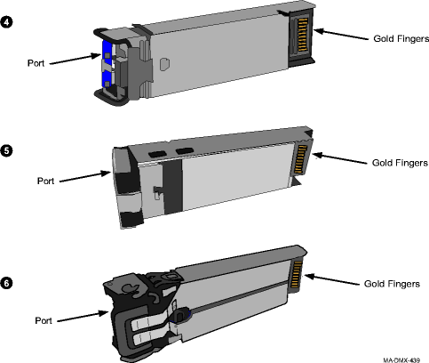
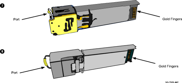 | ||||||||||
5 |
Important! Optical pluggable transmission modules are shipped with a dust cover installed into the ports to maintain cleanliness during storage and/or transportation. It is recommended that the dust cover be kept in place to maintain cleanliness until the cabling is connected. With proper care and handling, cleaning the pluggable transmission modules should not be necessary. If required, clean the optical pluggable transmission module. Reference: Procedure 14-29: Clean optical pluggable transmission module | ||||||||||
6 |
Referring to Step 4, what type of latching mechanism does your module have?
| ||||||||||
7 |
Before inserting the module, the latch must be in the closed position. With the dust cover in place, the latch is in the closed position. Figure 4-10 shows the open and closed position of the latch. Depending on your PTM type, the appearance of the port opening and latch mechanism may vary. Figure 4-10: Latch type 3 (opened and closed)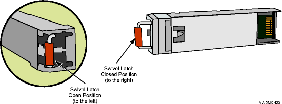 | ||||||||||
8 |
Proceed to Step 10. | ||||||||||
9 |
Before inserting the module, the latch must be in the closed position. With the dust cover in place, the latch is in the closed position. Figure 4-11 shows the open and closed position of the latch. Depending on your PTM type, the appearance of the port opening and latch mechanism may vary. Figure 4-11: Latch type 4, 5, 6, 7 and 8 (opened and closed)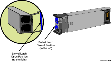 | ||||||||||
10 |
With your left hand, hold the pluggable transmission module by the dust cover (optical) or port end (electrical). The ports are in your left hand and the gold fingers are visible (facing you). (Do not insert pluggable transmission module). | ||||||||||
11 |
Rotate the module; the dust cover or port end is facing you and the gold fingers are pointing away from you and are facing to the right. (Do not insert pluggable transmission module). | ||||||||||
12 |
Insert the pluggable transmission module in the required socket of the circuit pack faceplate. Confirm that the pluggable transmission module is locked in the socket. Verify that all unused sockets on the circuit pack are equipped with dust covers. Figure 4-12: Insert pluggable transmission module into socket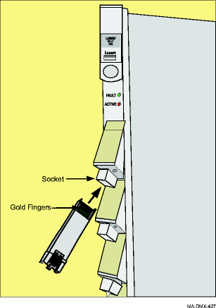
Result: Select View → Refresh System View and the port appears in the WaveStar® CIT System View indicating successful installation. If response is not correct, replace the pluggable transmission module. If the pluggable transmission module fails when inserted, and another pluggable transmission module in the shelf fails at the same time, replace the newly-installed pluggable transmission module. Each pluggable transmission module has unique internal data for warranty purposes. If this data for any reason is not unique, both pluggable transmission modules with the duplicated information will be declared failed. For information on replacing a pluggable transmission module, refer to the Alcatel-Lucent 1665 Data Multiplexer (DMX) Alarm Messages and Trouble Clearing Guide, 365-372-302. | ||||||||||
13 |
Push on the dust cover or port end to insert the module. The latch automatically catches when the module is inserted. The module is secure. To verify that the pluggable transmission module is properly latched in the cage, gently pull the pluggable transmission module (parallel to the direction the pluggable transmission module was installed). Do not rotate the swivel latch or activate the de-latching feature on the pluggable transmission module. | ||||||||||
14 |
| ||||||||||
15 |
Test the SONET optical port for proper operation, if required.
Reference: Procedure 14-6: Connect OLIU optical loopbacks | ||||||||||
16 |
If required, repeat this procedure to install additional pluggable transmission modules. | ||||||||||
17 |
From the System View window, click the Alarm List button to obtain the NE Alarm List. Verify that no alarms, protection switches, protection switch lockouts, and loopbacks are present for the ports just installed. Result: No alarms should be present for the ports just installed. | ||||||||||
18 |
If required at this time, provision circuit pack and/or port parameters for service. Reference:
End of steps |