Procedure 12-11.6: Verify spanning tree configuration
 Overview
Important!
This is not a stand-alone procedure. Perform this procedure only as directed by another procedure.
Use this procedure to verify the spanning tree configuration.
 Spanning tree network example
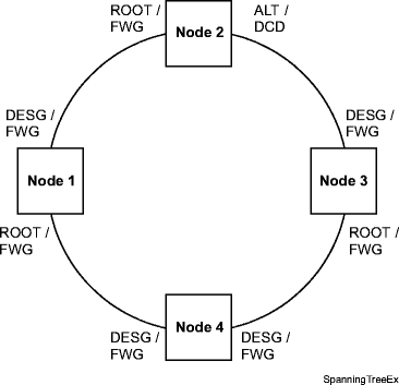
The following figure shows an example of a simple spanning tree network in a ring configuration with the spanning tree role and spanning tree status of each participating port.

The spanning tree role values are:
-
ROOT - Port is used for transmission and is the best path to the root node
-
DESG (Designated) - Port is used for transmission; however, the port is not the best path to the root node
The spanning tree status values are:
In this example, Node 4 is elected the root node by the spanning tree protocol. The root node can be identified by observing the spanning tree role of the participating ports. At the root node, all the participating ports have a spanning tree role of either DESG (designated) or ALT (alternate). The participating ports at the root node do not have a spanning tree role of ROOT.
Because there is a transmission loop in the example spanning tree network, the spanning tree role of a port at Node 2 is ALT (alternate) and the port is not used for transmission.
The spanning tree role of the remaining participating ports in the example is DESG (designated).
In this example, all ports have a FWG (forwarding) spanning tree status, except for the ALT port at Node 2. The ALT port has a DCD (discarding) or BLK (blocked) spanning tree status.
Steps
Complete the following steps to verify the spanning tree configuration.
1 |
Using office records and the work instructions determine the affected Ethernet spanning tree networks to be verified. Make a sketch of each spanning tree network with all participating nodes/ports using Rapid Spanning Tree Protocol and their connectivity. Reference: Refer to the example in Spanning tree network example. | ||||||
2 |
Identify a spanning tree network to be verified. | ||||||
3 |
At each node in the spanning tree network, select View → Data → Spanning Tree Group to access the required spanning tree group and record the required Port Role and Status parameter values for the participating ports. | ||||||
4 |
Important! There must be exactly one root node in the spanning tree network. At the root node, all the participating ports have a Port Role of either DESG (designated) or ALT (alternate). None have ROOT. Using the information obtained in the previous step, determine the root node by observing the Port Role of the participating ports at each node. | ||||||
5 |
For all nodes except the root node, verify that each node has one participating port with a Port Role of ROOT. | ||||||
6 |
Verify the appropriate forwarding status of the remaining ports.
| ||||||
7 |
If any port has a Status of DISF or DISA, clear all Ethernet-related alarms/conditions and/or verify provisioning using office records. If required, change the existing spanning tree configuration. Reference:
If required, contact Technical Support Services (TSS) for assistance in changing the spanning tree configuration. | ||||||
8 |
If required, repeat this procedure from Step 2 to verify another spanning tree network. End of steps |