Procedure 11-40.2: Add node to Ethernet ring protection (ERP) ring
 Overview
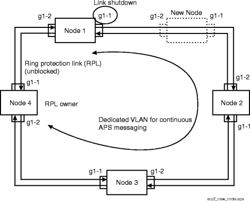
Use this procedure to add a new node to an Ethernet protection ring (ERP). See Figure 11-57, Add node to existing Ethernet ring protection (ERP).
Step
1 |
Login to one of the nodes in the ERP. |
2 |
Make sure that the ring is in the idle state. From the Navigation menu, select View → Data → ERP. Select the circuit pack associated with the ERP. TL1 command: rtrv-erp. In the ERP display, verify that the ERP Instance State is ENRB (No Request (RPL blocked). Note the VLAN ID and Maintenance Level. |
3 |
Login to the new node being added. |
4 |
From the System View menu, select Configuration → Data → Create/Modify/Delete ERP. Select the LNW70/170 with the ports associated with the ERP. Result: The ERP configuration screen displays. |
5 |
Click the Add button, then enter the ERP ID and the port IDs (Port 1 and Port 2) associated with the ERP. At this time, select DISABLE for the ERP State. Enter the remaining parameters as required. The ports must be in the same virtual switch. The port cannot be part of a spanning tree (the port’s spanning tree Port Mode must be disabled), or LAG, or another ERP instance. Reference: See Table 11-16, ERP configuration parameters (ent-erp). |
6 |
Click Apply to create the ERP and associate the links. Click Close to exit. |
7 |
Login to one of the two nodes adjacent to the link which will be replaced with the addition of the new node. Shut down the ERP link that will be replaced. From the System View, select Configuration → Equipment. Expand the circuit pack details.
Result: The node signals SF and unblocks the ring protection link (RPL). |
8 |
Wire the new node into the ring (the other adjacent link should also signal SF until the new link is working). Check that the link that is not shut down is working. |
9 |
Login to the new node being added. |
10 |
Enable the ERP at the new node. Enter Configuration → Data → Create/Modify/Delete ERP. Select the circuit pack. Set the ERP State to ENABLE, enter any remaining parameters, then click Apply. |
11 |
Login to the adjacent node where you disabled the link in Step 7. From the System View, select Configuration → Equipment. Expand the circuit pack details.
|
12 |
Verify that the link is working. End of steps |
Figure 11-57: Add node to existing Ethernet ring protection (ERP)
