Procedure 11-40: Provision Ethernet ring protection (ERP)
 Overview
Use this procedure to configure Ethernet ring protection (ERP).
The procedures in this section cover the following:
Ethernet ring protection provides switching for LNW70/170 Ethernet links connected in a ring configuration.
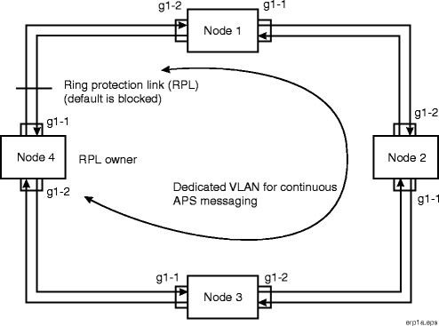
Figure 11-50, Ethernet ring protection shows a four-node ring. One of the links on Node 4 has been provisioned to be the Ring Protection Link (RPL). This is the link that by default is blocked for normal traffic. Node 4 is therefore the RPL Owner and blocks traffic bidirectionally. Switching is revertive – when a failure clears in the ring, the RPL is blocked (after a wait-to-restore delay). The ring has a VLAN dedicated to APS signaling, called the R-APS channel.
The LNW70 circuit pack supports switched and private line applications. The LNW170 offers all the features on the LNW70. In addition, the LNW170 can be equipped in pairs in an equipment protection configuration. There are 4 FE and 4 GbE LAN ports available on the LNW70/170. Up to 32 VCGs can be supported on the circuit pack. ERP is supported in protected and unprotected mode but only for switched applications.
Links supporting ERP are not required to all be the same rate; the ring can contain a mix of FE and GbE ports, or it can contain a mix of VCGs with different bandwidths, or a mix of FE/GbE ports and VCGs. It is up to the user/network designer to make sure that the ERP ring is appropriately sized for the application.
The following are some considerations for ERP support on LNW70/170:
-
ERP is supported on optical and electrical SFP-based LAN ports on the LNW70/170, as well as the VCGs.
Note that protection switch times are 50 msec. Detection times have been optimized for optical ports only.
-
LCAS protection should be disabled on VCGs that are ERP-controlled by keeping the LCAS Hold-off Timer set to 99999 (Infinity).
-
When the companion slots are equipped with LNW170, the ports on two circuit packs may be working independently when the circuit pack slot protection state is provisioned as UNPROT, or paired LAN ports 1, 2, 5 and 6 may be in a equipment protection mode when provisioned as PROT. Ports 3, 4, 7 and 8 cannot be used.
- In equipment-unprotected mode (Slot Protection State = UNPROT), the following is supported:
- In equipment-protected mode (Slot Protection State = PROT), the following is supported:
-
UNPROT to PROT transitions are not allowed if there are any LAN-based ERPs, but are allowed with VCG-based ERPs
-
Four LAN ERP instances per UNPROT circuit pack is supported. In addition to the LAN port, ERP on VCG ports is also supported. For a protected LNW170 in DMX/DMXtend, up to 16 ERP instances is supported on VCGs.
For an unprotected LNW70/170 in DMX/DMXtend up to 20 ERP instances (main or sub-ring) is supported (on VCGs and/or Ethernet ports).
ERP
Figure 11-50: Ethernet ring protection
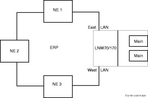
ERP on LAN ports (UNPROT)
Figure 11-51: ERP on LNW70/170 unprotected LAN ports
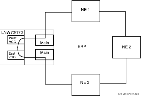
ERP on VCG ports (UNPROT)
Figure 11-52: ERP on LNW70/170 unprotected VCG ports
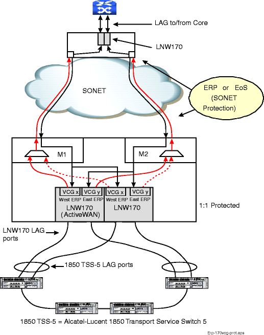
ERP on LNW170 VCG ports (PROT)
Figure 11-53: ERP on LNW170 protected VCG ports
Dual Ring Interconnection - G.8032v1 Amendment 1
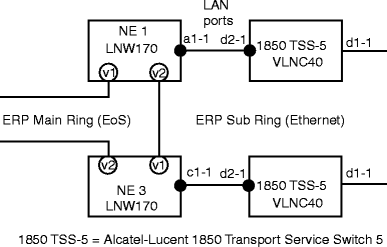
In dual ring interconnection (DRI), two ERP rings “share” a segment. In its simplest form a segment is composed of two interconnection nodes (ICN) and a shared link. For example, see Figure 11-54, Basic DRI with ERP. Only one of the rings takes responsibility for protecting the shared link. This is the “Main” ring. The other ring is called “Sub” ring. The Main ring is responsible for tunneling the R-APS PDUs of the sub-ring. This is called the R-APS virtual channel.
The Main ring and its sub-ring use different R-APS VLANs. The R-APS VLAN of the sub ring is considered regular data traffic for the Main ring (and is protected as such). Only ICN nodes need to be DRI-aware. A node is an ICN node if it has a sub-ring terminating on a main ring. Other (non-ICN) nodes simply run the single-ring ERP (and in fact don’t know if they belong to a main ring or sub ring).
The two rings work independently, the main ring controlling the shared segment. They each have an RPL. A protection switch in the Main ring does not affect the sub-ring because the sub ring should still be able to hand off traffic to the Main ring via either of the interconnection nodes. This is also true if the shared link fails.
Figure 11-54: Basic DRI with ERP
Rings can be cascaded into a ladder configuration. A sub-ring assumes the role of main ring for another sub-ring. See Figure 11-55, ERP DRI ladder example.
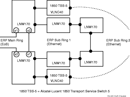
Rings may be multi-ring. Two (or more) sub-rings are connected to the same Main ring over the same shared link. See Figure 11-56, ERP DRI multi-ring example.
Figure 11-55: ERP DRI ladder example
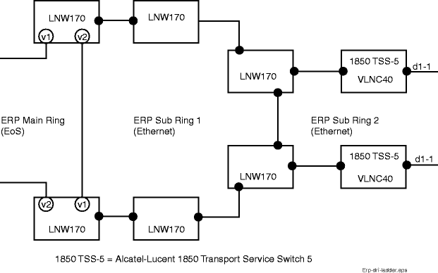
Figure 11-56: ERP DRI multi-ring example
ERP parameters
Table 11-16: ERP configuration parameters (ent-erp)
Step
1 |
Perform the following as required:
End of steps |