Procedure 10-12: Provision DS1/DS3 locked cross-connections on a UPSR
 Overview
Use this procedure as an example for provisioning locked VT1.5 or STS-1 cross-connections. Locked cross-connections consist of a cross-connection between a DSn port and a tributary on one side only of a UPSR ring, for example, a1-1-3-4 to m1-1-2-3-4. Note that the AIDs are that of a ring channel (a1, m1).
This procedure uses examples for DS1 and DS3 type cross-connections to illustrate the steps involved in cross-connections in a single UPSR ring configuration. This procedure uses the CIT Cross-Connection Wizard commands to illustrate the provisioning of the cross-connections. The TL1 ent-crs-( ) command may be used to perform the same provisioning.
Additional considerations when provisioning locked cross-connection:
-
Cross-connections are 2-way using two 1-way cross-connections performed by the DSn Locked cross-connection type from the CIT Cross-Connection Wizard.
-
In the example (a1-1-3-4 to m1-1-2-3-4), for systems not equipped with Very Large Fabric (VLF) OLIU main circuit packs, cross-connections on the same companion VT timeslot within the same STS of a locked cross-connection are denied to the other side (for example, m2-1-2-3-4 to b2-2-2-3-4). However, the same ring timeslot can be reused on non-adjacent spans. For systems equipped with VLF OLIU main circuit packs, there is no restriction. The companion VT timeslot within the same STS of a locked cross-connection is allowed to the other side.
For systems not equipped with VLF OLIU main circuit packs, cross-connections, at the local node, of the same companion STS to the other side are also denied (for example, m2-1-2 to c1-2). For systems equipped with VLF OLIU main circuit packs, cross-connections of the same companion STS to the other side is allowed.
Cross-connections of different timeslots within the same STS are accepted (for example, m2-1-2-7-4 to b2-2-2-7-4).
 Before you begin
Prior to performing this procedure:
-
Refer to Before you begin and Required equipment in this chapter.
-
Refer to Electrostatic discharge in Chapter 1, Safety.
-
Verify that you have the work instructions for this procedure stating the circuit pack and port options to be set, the pass-through and terminating end nodes, and cross-connections being made.
-
Verify the network has been established and that all necessary circuit packs and port options have been provisioned for the service being established.
Steps
Perform the following steps to make the necessary locked cross-connections.
1 |
Connect the PC and establish a WaveStar® CIT session. Reference: Procedure 14-2: Connect Personal Computer (PC) and establish WaveStar® CIT session |
2 |
Log in to any node in the network and retrieve a map of the network which lists all the systems and how they are connected to each other. From the System View menu select Administration → OSI Routing Map or Administration → OSI Neighbor Map. |
3 |
Verify that the system configuration is the same as specified on the work order or circuit order. |
4 |
From work order or circuit order, determine the terminating (drop) nodes and the pass-through nodes for the service being established. Important! In ring configurations, you should use the following general rules in establishing cross-connections in each ring. Cross-Connect Rules
|
5 |
Log in to each node in the network and verify that each shelf is properly equipped for the service being established. From the System View menu select View → Equipment. |
6 |
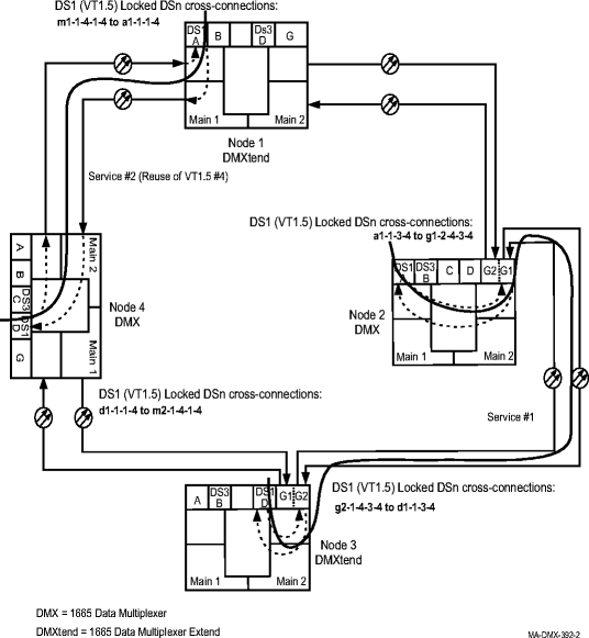
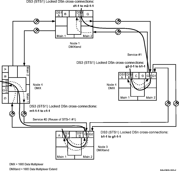
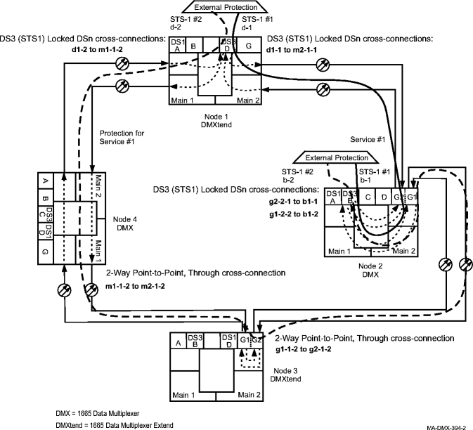
From work order or circuit order, determine the cross-connections to be made at each node associated with the service to be established. See Figure 10-17, DS1 locked cross-connections on a UPSR (unprotected), Figure 10-18, DS3 locked cross-connections on a UPSR (unprotected) and Figure 10-19, DS3 locked cross-connections on a UPSR (protected externally) for DS1/DS3 cross-connection examples. Important! Cross-connections supporting DS3 services are STS-1 cross-connections. Cross-connections supporting DS1 services may be either STS-1 or VT1.5 cross-connections. Use VT1.5 cross-connections for DS1 services if you expect to cross connect only some of the VT1.5 signals in the STS-1 channel. If STS-1 cross-connections are made at a shelf, there is a fixed mapping of all 28 VT1.5 cross-connections to a specific shelf group. |
7 |
Starting at one of the terminating nodes for the circuit being established, at each node in the ring select View → Cross-Connections from the System View menu to verify that the cross-connections specified on the work order or circuit order may be made. If the cross-connections are already assigned to another service or improperly assigned, refer trouble to the organization responsible for facility design. Improperly assigned cross-connections may have to be deleted. |
8 |
At all non-terminating nodes in the network, provision pass-through cross-connections. From the System View menu select Configuration → Cross-Connections, then use the Cross-Connection Wizard to make the cross-connections. Select 2-Way Point-to-Point, Through for pass through cross-connections. |
9 |
At the terminating (add/drop) nodes of the circuit being established, establish the terminating cross-connections. From the System View menu select Configuration → Cross-Connections, then use the Cross-Connection Wizard to make the Locked DSn cross-connections. Important! The channel mode provisioning feature provides In-Service, Automatic, or Not Monitored states for VT and STS channels similar to the port modes for DS1 and DS3 ports. At installation, or when a cross-connection is made to a point of termination, the channel is in the Automatic mode and alarming is suppressed until a valid signal is received. The channel must receive a good signal from the side of the ring being used to cause the channel to transition to in-service. Locked DSn cross-connections may be made between OLIUs and DS1 or DS3 interfaces, but not TMUX interfaces. Also, remember that the AIDs for the locked cross-connections are that of a ring channel, for example m1-1-4-1-4 or g2-2-1. |
10 |
Verify that the proper connection has been made. From the System View menu select View → Cross-Connections. If changes are required, return to the Cross-Connect Wizard to make them. |
11 |
After all cross-connections have been made, verify that the channels have gone in service at each terminating node. From the System View menu at each terminating node, select View → Equipment. Result: The View Equipment window opens. Alarms are not reported until the channel state transitions to in-service (IS) which happens only when a good signal is received. Since there is a connection only to one side of the UPSR ring, no alarms are reported until all upstream connections are correct. |
12 |
Expand the details for the circuit pack being used. Select the required DS1/DS3 port, then click Select at the bottom of the window. Verify the port AID is correct at the top of the parameter display. |
13 |
Under Port Data/Fault in the parameter display, verify the Port Monitoring Mode is IS (in service). If the Port Monitoring Mode is IS, then Stop, you have completed this procedure. Otherwise, perform one of the following:
Reference: Alcatel-Lucent 1665 Data Multiplexer Extend (DMXtend) Alarm Messages and Trouble Clearing Guide, 365-372-326 End of steps |
Figure 10-17: DS1 locked cross-connections on a UPSR (unprotected)

Figure 10-18: DS3 locked cross-connections on a UPSR (unprotected)

Figure 10-19: DS3 locked cross-connections on a UPSR (protected externally)
