Procedure 10-11: Establish dual ring interworking (DRI) connections
 Overview
This procedure provides an example for configuring basic dual ring interworking connections (DRI). See Figure 10-9, DRI configuration example for an example.
This procedure provides examples of the steps involved in making the proper cross-connections at the DRI interconnecting nodes. It is not intended for establishing complete service from an end node to an end node (for example, from Node 1 to Node 6). Although, once the DRI connections are made at the interconnecting nodes, establishing service from an end node to an end node only requires the proper pass-through cross-connections at intermediate nodes and add/drop cross-connections in the terminating end nodes.
 Privilege level
You must login as either a Privileged or General user to complete this procedure.
Important!
The following procedure is based on a hypothetical example. You can use this example procedure to apply the basic concepts to the procedure you want to perform.
This procedure assumes that the individual rings being connected have been established and are working properly.
 Before you begin
Before you begin this procedure, you must:
-
Refer to Before you begin and Required equipment in this chapter.
-
Refer to Laser safety and Electrostatic discharge in Chapter 1, Safety.
-
Identify the nodes in the network and determine which nodes are the interconnecting DRI nodes.
-
Identify which function slots in the DRI nodes are going to be used to make the connections.
-
Be able to log in to the NE with the WaveStar® CIT and be familiar with the functions of the WaveStar® CIT.
Steps
Complete the following steps to perform DRI connections.
1 |
Use the WaveStar® CIT to log in to the nodes, if not already performed. Reference: Procedure 14-2: Connect Personal Computer (PC) and establish WaveStar® CIT session |
2 |
On the System View menu at each node, select Administration → OSI Neighbor Map to retrieve a node-to-node listing of every node in the network. Important! If a drawing of the network is not provided with the work instructions, it is recommended that you draw a simple diagram of the ring (indicating node-to-node connections) and list each node's TID. This command may take several minutes to complete depending on the size of the network. Result: The OSI Neighbor Map window opens. See Figure 10-9, DRI configuration example for an example of a final configuration. In this example, two UPSR rings are being interconnected in a DRI configuration using STS1 cross-connections between two pairs of interconnecting nodes (Nodes 2 and 3, and Nodes 4 and 5), one pair in each ring. Note that the cross-connections are STS cross-connections. In this figure, the main ports are on the UPSR and the low-speed ports are used as the add/drop ports. The add/drop ports may be UPSR, 1+1, 0x1S1 or 0xS2, OC-N ports, or an electrically protected EC1 port. For this example, we assume the low speed ports are configured as UPSR ports. This example is only one of many possible configurations. In this example one could reverse the roles of the main OLIUs and the low speed circuit packs at any of the nodes to form another configuration. Also, a low speed UPSR could be used in place of the Main OLIUs at any of the interconnecting nodes. Figure 10-9: DRI configuration example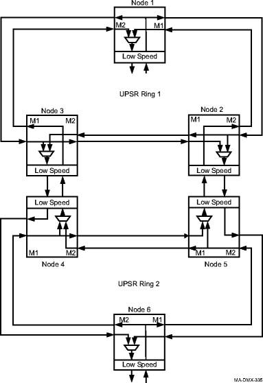 |
3 |
From the System View menu, select View → Equipment and verify that all circuit packs have been installed and ports have been provisioned and connected at each interconnecting DRI node. For example, at nodes 2, 3, 4, and 5 in Figure 10-9, DRI configuration example. Important! Before performing the DRI cross-connections in this procedure, the optical or electrical interconnection between the DRI nodes must be completed. If circuit packs have not been installed, the ports have not been provisioned, or the proper interconnection application has not been performed, use the procedures in this manual to install, provision, and connect the required circuit pack ports. The add/drop ports may be UPSR, 1+1, or electrically protected EC1 ports. |
4 |
From the System View menu at each DRI node, select Configuration → Cross-Connections to start the Cross-Connection Wizard. Result: The Cross-Connection Wizard screen opens. |
5 |
Select Create a new cross-connection, then click Next at the bottom of the screen. |
6 |
Select UPSR Dual Ring Interworking, then click Next at the bottom of the screen. |
7 |
Use the Select button to choose the UPSR and then the Add/Drop Tributary. Click Next to continue. Note the direction of cross-connections (East or West) in the Cross-Connection Wizard. For example, see Figure 10-10, Cross-Connection examples at node 3 and Figure 10-11, Cross-Connection examples at node 2 for the cross-connections at Nodes 2 and 3. Figure 10-10: Cross-Connection examples at node 3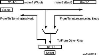
Figure 10-11: Cross-Connection examples at node 2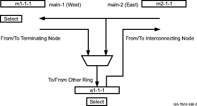 |
8 |
Enter a Circuit Identifier if required. Verify the cross-connections, then click Finish to execute the command. |
9 |
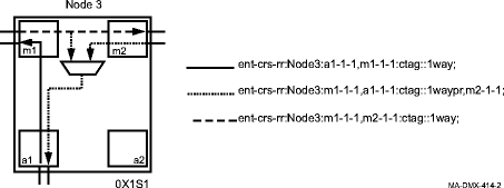
Repeat these steps from Step 4 to make the cross-connections at each DRI node. See Figure 10-12, Cross-Connections for DRI with UPSR protected OC-n add/drop ports example for an example of the cross-connections that are made at each node to complete the final configuration as shown in Figure 10-9, DRI configuration example. The example uses TL1 commands to illustrate the different cross-connections that are made when using the Cross-Connection Wizard. The View → Cross-Connections command at each of the DRI nodes shows the individual cross-connections made from the Cross-Connection Wizard. Cross-connections are a combination of 1waypr and 1way. Refer to Figure 10-13, Basic UPSR DRI cross-connections with UPSR protected OC-n add/drop port through Figure 10-16, Basic UPSR DRI cross-connections with 0X1Sn (0x1) protected OCn add/drop port for examples of different add/drop port configurations in the basic UPSR DRI application. End of steps |
Figure 10-12: Cross-Connections for DRI with UPSR protected OC-n add/drop ports example
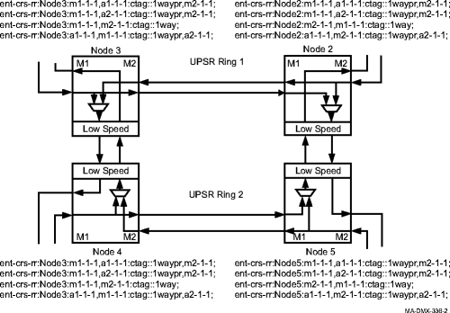
Figure 10-13: Basic UPSR DRI cross-connections with UPSR protected OC-n add/drop port
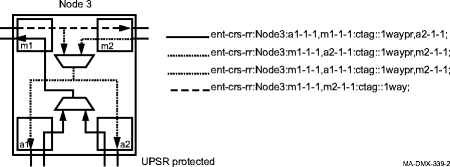
Figure 10-14: Basic UPSR DRI cross-connections with EC-1 add/drop port
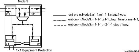
Figure 10-15: Basic UPSR DRI cross-connections with 1+1 protected OC-n add/drop port
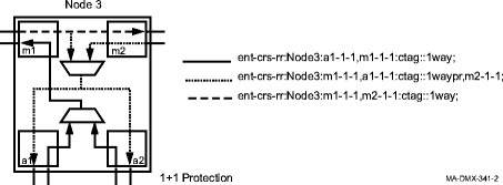
Figure 10-16: Basic UPSR DRI cross-connections with 0X1Sn (0x1) protected OCn add/drop port
