Procedure 11-11: Add bandwidth to a point-to-point UPSR protected GbE service (802.1q mode)
 Overview
Use this procedure as an example for adding bandwidth to an in service point-to-point UPSR protected GbE Ethernet service using circuit packs not supporting LCAS. For circuit packs supporting LCAS, see Procedure 11-25: Provision LCAS, add/enable/remove tributaries.
This procedure provides an example for adding bandwidth to an in service point-to-point UPSR protected GbE Ethernet service with minimal service interruption. This example uses the 802.1q tagging mode.
This procedure uses TL1 commands and specific WaveStar® CIT menu selections to illustrate the detailed provisioning parameters. If you prefer, you can use the Cross-Connection Wizard to perform the cross-connection provisioning in this procedure and Configuration → Data → Create VLAN to provision new VLANs. From the System View menu, select Configuration → Cross-Connections to invoke the wizard.
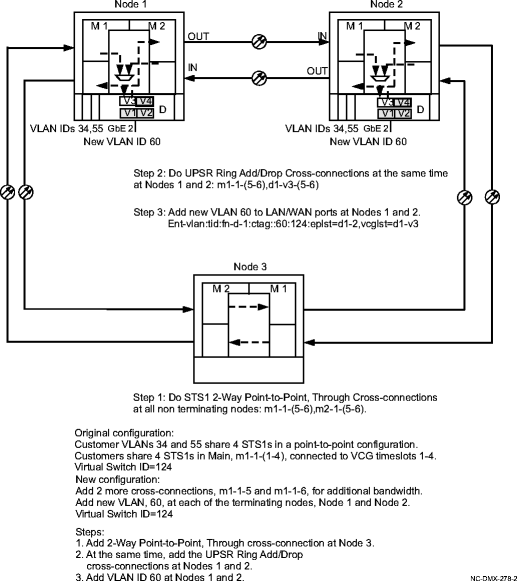
See Figure 11-8, Example of adding bandwidth on UPSR for example.
Important!
To minimize service interruption, plan the addition of cross-connections. For example, do any new pass-through cross-connections first. Then at the appropriate time, coordinate and make the add/drop cross-connections at the terminating nodes at the same time, as close as possible.
 Before you begin
Prior to performing this procedure, refer to Before you begin and Required equipment in this chapter and you must have complete work instructions for this procedure that detail:
-
The network configuration and the terminating Ethernet nodes.
-
The shelf slots, circuit packs, ports, and VCGs being provisioned.
-
The number and type of additional cross-connections to be made at each node.
-
Notify the customers on the existing service of the impending service interruption and coordinate your activities accordingly.
-
Plan the activity of adding cross-connections to minimize service interruption.
Steps
Use this procedure as an example for adding bandwidth (cross-connections) to a point-to-point UPSR protected GbE Ethernet service using the 802.1q tagging mode.
1 |
Use the WaveStar® CIT to log in to each of the terminating nodes, if not already performed. Reference: Procedure 14-2: Connect Personal Computer (PC) and establish WaveStar® CIT session |
2 |
On the System View menu, select Administration → OSI Neighbor Map command and note the NEs connected to Main 1 and Main 2. Access each of the NEs identified and select the Administration → OSI Neighbor Map command and note the NEs connected to Main 1 and Main 2. Repeat the above until the backbone ring can be sketched. Important! If a drawing of the network is not provided with the work instructions, it is recommended that you draw a simple diagram of the ring (indicating node-to-node connections) and list each node's TID. Result: The OSI Neighbor Map window opens. |
3 |
Verify that the system configuration is the same as specified on your work instructions. |
4 |
From your work instructions, determine the circuit pack, ports, and cross-connections to be made at each node associated with the service being added. |
5 |
At each node in the network, use the View → Cross-Connections command from the System View menu at each node to verify that the new cross-connections are available for assignment at each NE. If any of the new cross-connections are already assigned, you must resolve the problem before continuing with this procedure. |
6 |
ESTABLISH SONET PASS THROUGH CROSS-CONNECTIONS Determine the necessary 2-Way Point-to-Point, Through STS-1 cross-connections to be made at each non terminating node in the network. |
7 |
One at a time at each non terminating node in the network, use the TL1 ent-crs-sts1 command to provision the pass-through cross-connections. Or, select Configuration → Cross-Connections from the System View menu to start the Cross-Connection Wizard. Use the Cross-Connection Wizard at each of the non terminating nodes in the network to provision the 2-Way Point-to-Point, Through cross-connections. Important! Note that cross-connections at the terminating nodes are add/drop and cross-connections at the non terminating nodes are pass-through. Reference: Procedure 11-15: Make cross-connections for Ethernet service |
8 |
From the System View menu, select View → Cross-Connections at each non terminating node to verify that the proper connections have been made. |
9 |
ESTABLISH SONET ADD/DROP CROSS-CONNECTIONS At each terminating node in the network, coordinate your activities to activate the necessary cross-connections at the same time. Note that there will be some service interruption. Use The TL1 ent-crs-sts1 command to provision the add/drop cross-connections. Or, select Configuration → Cross-Connections from the system view menu to start the cross connection wizard. Use the cross connection wizard at each of the terminating nodes in the network to provision the UPSR Ring Add/Drop cross-connections. Important! Enter all your parameters for the cross-connections and coordinate with the other end as to when you enter/apply the command. |
10 |
After all cross-connections are made, click on the Alarm List button on the System View window and verify no alarms are present. |
11 |
If alarms are present, look for missing or improperly made cross-connections. Reference: Alcatel-Lucent 1665 Data Multiplexer Extend (DMXtend) Alarm Messages and Trouble Clearing Guide, 365-372-326 |
12 |
ASSIGN VLAN IDs If adding new customers, use the TL1 ent-vlan command to assign the new customer VLAN ID to the associated LAN ports and VCG WAN ports. Or select Configuration → Data → Create VLAN command from the CIT System View menu to open the Create New VLAN provisioning window. End of steps |
Figure 11-8: Example of adding bandwidth on UPSR
