Procedure 10-13: Configure LNW20 TMUX/DS3/EC1 applications
 Overview
This procedure provides examples for TMUX/DS3/EC1 applications and cross-connections.
The examples show port provisioning and cross-connections to various interfaces to illustrate applications for TMUX configurations. This procedure uses TL1 commands to illustrate the provisioning. The same provisioning may be made using the CIT Cross-Connection Wizard commands.
One-way TL1 command cross-connections are used in the examples due to the complexity of the signal paths involved.
Important!
For detailed information about cross-connections and restrictions regarding circuit pack types, rates, and VT granularity, refer to Alcatel-Lucent 1665 Data Multiplexer Extend (DMXtend) TL1 Message Details, 365-372-328.
 Before you begin
Prior to performing this procedure:
-
Refer to Before you begin and Required equipment in this chapter.
-
Refer to Electrostatic discharge in Chapter 1, Safety.
-
Verify that you have the work instructions for this procedure stating the circuit pack and port options to be set and the cross-connections being made.
Steps
Complete the following steps to provision the TMUX applications.
1 |
Click the Alarm List button to obtain an NE Alarm List and verify that no alarms are present. Clear all alarms before continuing this procedure. Reference: Alcatel-Lucent 1665 Data Multiplexer Extend (DMXtend) Alarm Messages and Trouble Clearing Guide, 365-372-326 |
2 |
From the System View menu at each terminating node, select View → Equipment to verify that the proper service and protection circuit packs have been installed and provisioned in the Function Unit/Growth groups used for this service. |
3 |
If circuit packs have not been installed or provisioned, install and provision circuit packs as required. Reference: Chapter 4, Install and provision circuit packs/OLIUs procedures |
4 |
If circuit pack ports have not been provisioned, provision circuit pack ports as required. Reference: Chapter 4, Install and provision circuit packs/OLIUs procedures |
5 |
Verify that the cable connections have been made from the terminating nodes to the cross-connect panel or equivalent connection points. |
6 |
Determine the necessary cross-connections for each node from the work instructions. |
7 |
Important! For detailed information about cross-connections and restrictions regarding circuit pack types, rates, and VT granularity, refer to Alcatel-Lucent 1665 Data Multiplexer Extend (DMXtend) TL1 Message Details, 365-372-328. Use the TL1 ent-crs-( ) command or select Configuration → Cross-Connections from the System View menu to access the Cross-Connection Wizard and create the required new cross-connections. Follow the Cross-Connection Wizard instructions to select the Rate, Type of Cross-Connection, Source/Destination, Circuit Identifier, and Source NE Name. |
8 |
Important! If the Port Monitoring Mode of a ported EC-1/DS3/constituent DS1 port is provisioned to NMON, the port is not monitored/alarmed and the port will not automatically transition to the IS (in-service) state when a good EC-1/DS3 signal (not EC-1/DS3 LOS, EC-1/DS3LOF, DS3 AIS) is detected. If the Port Monitoring Mode is provisioned to AUTO, the port automatically transitions to the IS (in-service) state when a good EC-1/DS3 signal (not EC-1/DS3 LOS, EC-1/DS3 LOF, DS3 AIS) is detected, and the port is monitored/alarmed. If a DS3 port transitions to IS, the constituent DS1 ports transition to IS. If the Port Monitoring Mode is provisioned to IS, the port is monitored and alarms are reported. User provisioning of a DS3 port is automatically applied to any constituent DS1 ports. Select View → Equipment to access the required ported EC-1/DS3/constituent DS1 ports and verify the value of the Port Monitoring Mode parameter. If required, select Configuration → Equipment to access ports and change the value of the Port Monitoring Mode parameter. The following methods may be used to change default monitoring and alarm reporting for ported EC-1/DS3/constituent DS1 ports.
|
9 |
Important! If the Port Monitoring Mode of a portless DS1 port is provisioned to NMON, the DS1 port is not monitored/alarmed and the port will not automatically transition to the IS (in-service) state when a good STS-1 tributary signal (not STS-1 AIS-P, LOP-P, UNEQ-P, SF) is detected. If the Port Monitoring Mode is provisioned to AUTO, the DS1 port automatically transitions to the IS (in-service) state when a good STS-1 tributary signal (not STS-1 AIS-P, LOP-P, UNEQ-P, SF) is detected, and the port is monitored/alarmed. If the STS-1 tributary transitions to IS, the constituent DS1 ports transition to IS. If the Port Monitoring Mode is provisioned to IS, the port is monitored and alarms are reported. User provisioning of the STS-1 tributary is automatically applied to the constituent DS1 ports. The constituent DS1 port states are controlled by the state of the Source STS-1 Tributary of the cross-connection from the OLIU/EC-1 to the DS3. Select View → Equipment to access the required source STS-1 tributary and portless DS1 ports and verify the value of the STS-1 Tributary Monitoring Mode and DS1 Port Monitoring Mode parameters. If required, select Configuration → Equipment to access the source STS-1 tributary and portless DS1 ports and change the value of the STS-1 Tributary Monitoring Mode and DS1 Port Monitoring Mode parameters. The following methods may be used to change default monitoring and alarm reporting for source STS-1 tributaries and portless DS1 ports.
|
10 |
Use the following examples for reference in configuring the TMUX applications. Figure 10-20: Example of basic DS3/EC1 STS-1 add/drop (like LNW16/LNW19/19B) configuration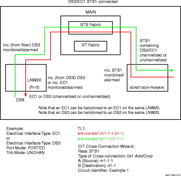
Figure 10-21: Example of basic TMUX channelized DS3 STS1-xconn to VT-based STS1 (like LNW18)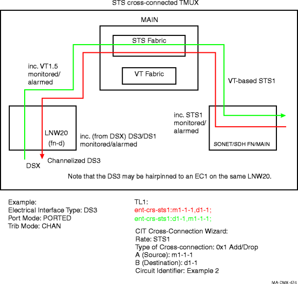
Figure 10-22: Example of basic EC1 VT add/drop (like LNW16/LNW19/19B) configuration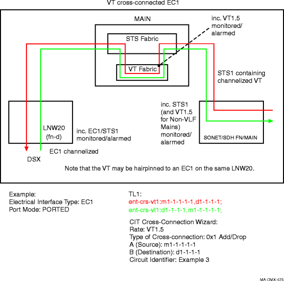
Figure 10-23: Example of basic TMUX (like LNW18) configuration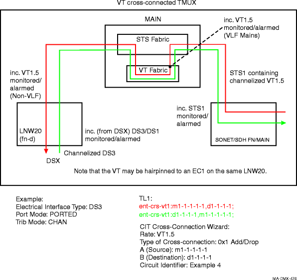
Figure 10-24: Example of DS1-in-DS3-in-STS1 portless TMUX to DS1 port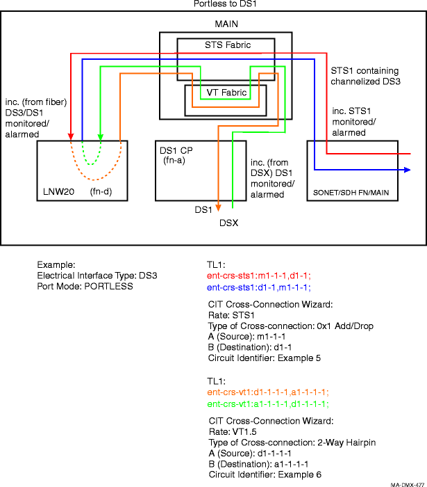
Figure 10-25: Example of DS1-in-DS3-in-STS1 portless TMUX to DS1-in-DS3 port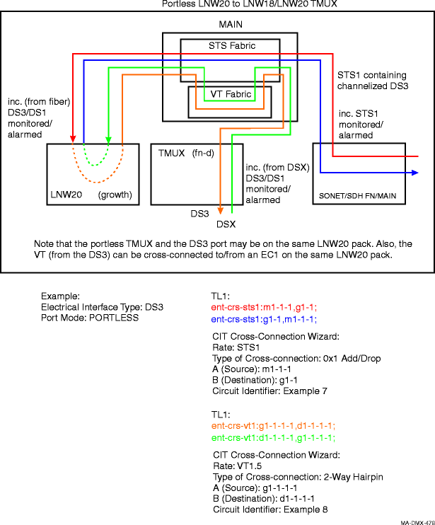 Figure 10-26: Example of DS1-in-DS3-in-STS1 portless TMUX to VT-in-STS1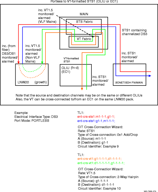 Figure 10-27: Example of DS1-in-DS3-in-STS1 portless TMUX to DS1-in-DS3-in-STS1 (DS1 grooming)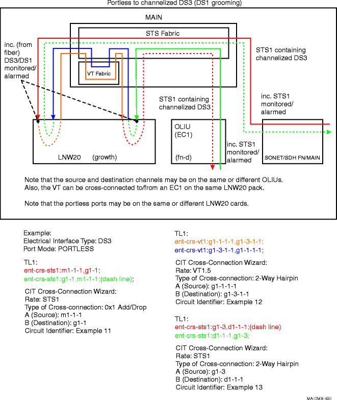 End of steps |