Procedure 10-3: Establish cross-connections
 Cross-connection rates
The Alcatel-Lucent 1850 TSS-5 supports VT1.5/STS-n or VC-n rate cross-connections. When the system interface standard parameter is provisioned to SONET, VT1.5, STS-1 STS-3c, and STS-12c (VLNC55 only) rate cross-connections are supported. When the system interface standard parameter is provisioned to SDH, VC-12, VC-3, and VC-4, and VC-44C (VLNC55 only) rate cross-connections are supported. Refer to Procedure 6-2: Provision system parameters to provision the Interface Standard parameter.
Cross-connection types
Alcatel-Lucent 1850 TSS-5 supports the following cross-connection types:
-
UPSR Ring Add/Drop (SONET only): A two-way cross-connection between a UPSR-protected tributary and a tributary in another UPSR/1+1/0x1 application or a tributary in function group A, B, C, or D. In the add direction, traffic is bridged to the same tributary in both rotations of the UPSR. In the drop direction, the path (tributary) selector monitors both tributaries independently, and selects traffic from one tributary based on performance criteria and technician/OS control.
-
Linear/Unprotected UPSR (SONET only): A two-way cross-connection between a tributary on one side of an UPSR interface and a tributary on a DS1 port (function group A) or a VCG port (function group C or D).
-
SNCP Ring Add/Drop (SDH only): A two-way cross-connection between a SNCP-protected tributary and a tributary in another SNCP/1+1/0x1 application or a tributary in function group A, B, C, or D.In the add direction, traffic is bridged to the same tributary in both rotations of the SNCP. In the drop direction, the path (tributary) selector monitors both tributaries independently, and selects traffic from one tributary based on performance criteria and technician/OS control.
-
Linear/Unprotected SNCP (SDH only): A two-way cross-connection between a tributary on one side of an SNCP interface and a tributary on an E1 port (function group A) or a VCG port (function group C or D).
-
1+1 Add/Drop: A two-way cross-connection between a 1+1-protected tributary and a tributary in another UPSR/SNCP/1+1/0x1 application or a tributary in function group A, B, C, or D. In the add direction, traffic is bridged to the same tributary in both lines. In the drop direction, the line selector monitors both lines independently, and selects traffic from one line based on performance criteria and technician/OS control.
-
2-Way Point-to-Point, Through: A two-way cross-connection between the two sides of a UPSR/SNCP node. Traffic received on a timeslot on one side of the UPSR/SNCP node is passed through to the same timeslot on the opposite side of the UPSR/SNCP node.
-
2-Way Hairpin: A two-way cross-connection between a DS1 port in function group A and a DS1 port within a channelized DS3 in function group B-3. The VLNC50 SONET/SDH Transport circuit pack supports up to 8 2-way hairpin cross-connections. The VLNC52/55 SONET/SDH Transport circuit pack supports up to 28 2-way hairpin cross-connections.
-
2-Way 0x1 Add/Drop: A two-way cross-connection between a ring channel on a main port which has an application value of 0x1 to another main port, which has the application value 0x1/1+1/UPSR/SNCP, or to a tributary in function group A, B, C, or D.
-
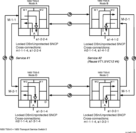
Locked DSn (SONET only): A two-way cross-connection between a tributary on one side of a UPSR interface and a tributary on a DS1 port (function group A).
-
Unprotected SNCP (SDH only): A two-way cross-connection between a tributary on one side of a SNCP interface and a tributary on a E1 port (function group A).
Refer to the Alcatel-Lucent 1850 Transport Service Switch (TSS-5) TL1 Command Guide for MSPP for detailed information about cross-connection types and restrictions.
Privilege level
You must log in as either a Privileged or General user to complete this procedure.
 Before you begin
Prior to performing this procedure:
-
Refer to Before you begin and Required equipment in this chapter.
-
Refer to Electrostatic discharge in Chapter 1, Safety.
-
Obtain the work instructions for this procedure.
-
Verify that the work instructions specify the terminating nodes, pass-through nodes, port/tributary addresses, and cross-connections to be established.
Steps
Complete the following steps to establish cross-connections in a network.
1 |
Log in to each node in the network and select Administration → OSI Neighbor Map to obtain the OSI Neighbor Map report. This report lists all the locally connected systems and how they are connected. Using this information, construct a diagram of the network topology. |
2 |
Verify that the network configuration is the same as specified in the work instructions. |
3 |
From work instructions, determine the terminating nodes and the pass-through nodes for the service being established. |
4 |
Log in to each node in the network and select View → Equipment to verify that each shelf is properly equipped for the service being established. |
5 |
Important! VT1.5 rate cross-connections support DS1 services. VC12 rate cross-connections support E1 services. STS-1 rate cross-connections support DS3 services. VC3 rate cross-connections support E3 services. From the work instructions, determine the required cross-connections at each node associated with the service to be established. General SONET cross-connection rules:
General SDH cross-connection rules:
Examples:
Reference: Refer to the Alcatel-Lucent 1850 Transport Service Switch (TSS-5) TL1 Command Guide for MSPP for detailed information about supported cross-connections, cross-connection rates, types, and restrictions. |
6 |
At all terminating nodes and pass-through nodes for the circuit being established, select View → Cross-Connections to obtain a current list of cross-connections. Verify that the cross-connections specified in the work instructions may be established. If the cross-connections are already assigned to another service or improperly assigned, contact the organization responsible for facility design. Improperly assigned or default cross-connections may have to be deleted. If required, select Configuration → Cross-Connections to access the Cross-Connection Wizard and delete the required cross-connections. |
7 |
If required, at all pass-through nodes select Configuration → Cross-Connections to access the Cross-Connection Wizard and establish the required pass-through cross-connections. Follow the Cross-Connection Wizard instructions to create the required 2-Way Point-to-Point, Through cross-connections. Result: When pass-through cross-connections are established at pass-through nodes, the default Tributary Monitoring Mode is NMON. In the NMON state, the tributary is not monitored/alarmed and will not automatically transition to the IS (in-service) state when a good signal (not LOP, AIS, UNEQ, SF) is detected. If required, select Configuration → Equipment to access the required tributary and change the value of the Tributary Monitoring Mode parameter to AUTO. In the AUTO state when a good signal (not LOP, AIS, UNEQ, SF) is detected, the Tributary Monitoring Mode automatically transitions to the IS (in-service) state, and the tributary is monitored/alarmed. |
8 |
At the terminating nodes, select Configuration → Cross-Connections to access the Cross-Connection Wizard and establish the required cross-connections. |
9 |
At the terminating nodes and the pass-through nodes, select View → Cross-Connections to obtain a current list of cross-connections and verify that the proper cross-connections have been established. If required, select Configuration → Cross-Connections to access the Cross-Connection Wizard and make cross-connection changes. |
10 |
At the terminating nodes and the pass-through nodes, click the Alarm List button to obtain the NE Alarm List and verify that no alarms are present. End of steps |
Cross-Connection Examples
Figure 10-1: Example of UPSR/SNCP Ring Add/Drop and 2-Way Point-to-Point, Through Cross-Connections in UPSR/SNCP
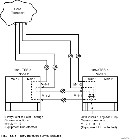
Figure 10-2: Example of 0x1 Add/Drop Cross-Connections
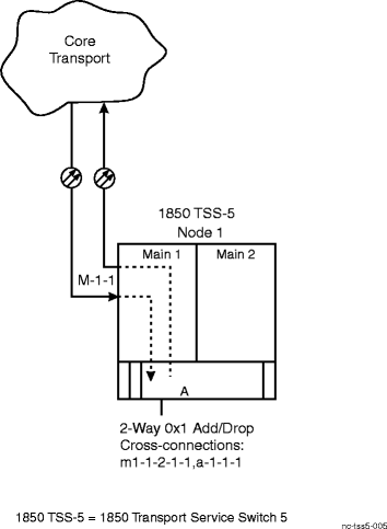
Figure 10-3: Example of Linear/Unprotected UPSR/SNCP Cross-Connections
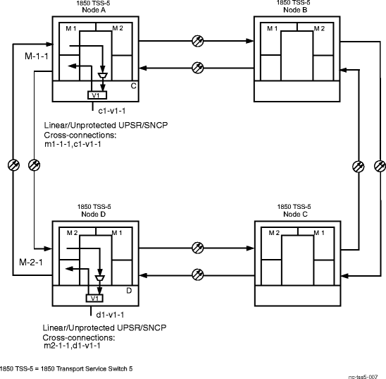
Figure 10-4: Example of 1+1 Add/Drop Cross-Connections
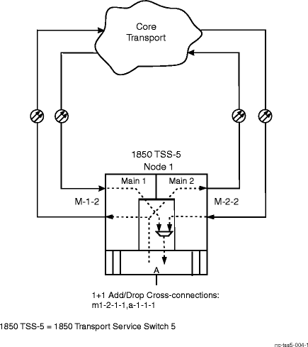
Figure 10-5: Example of 2-Way Hairpin Cross-Connections
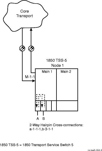
Figure 10-6: Example of Locked DSn/Unprotected SNCP Cross-Connections
