Procedure 17-2.9: Configure circuit emulation service with pseudowire protection
 Overview
Use this procedure to configure pseudowire protection when ces-mode is set to “mpls-php-enable” or “mpls-php-disable”.
When ces-mode is set to “ethernet”, no bfd related commands are supported. Also, the protectionmode command used to enable UPSR/SNCP protection is not supported.
When ces-mode is set the “ethernet”, basic protection for PWEs is supported using the psn-tunnel-protect command. Refer to the Alcatel-Lucent 1850 Transport Service Switch (TSS-5) Command Line Interface Guide, for help on using this command when ces-mode is set to “ethernet”.
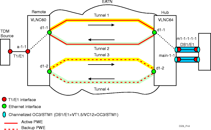
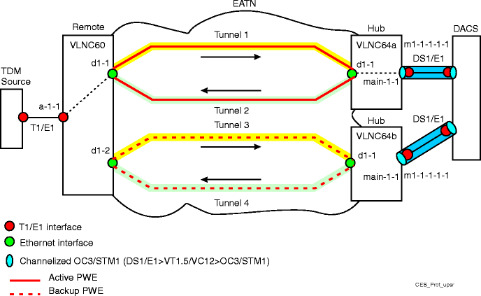
In addition to the general procedures used to configure circuit emulation service, other procedures are required to configure CES with protection. See Figure 17-8, Circuit emulation service protection and Figure 17-9, Circuit emulation service protection - UPSR/SNCP for examples.
Configuring CES with protection consists of the following steps in addition to the general CES configuration steps:
-
Configuring two tunnels in the forward direction (for example, tunnels 1 and 3) and two tunnels in the reverse direction (for example, tunnels 2 and 4).
-
Associate forward and reverse tunnels as protection pairs.
-
Configuring a pseudowire and associating it with a forward and reverse tunnel (creating a tunnel aggregate), for example, tunnel 1 & 2.
-
Configuring Bi-directional Forwarding Detection (BFD) on each Tunnel.
-
Enabling protection mode on the Hub site if UPSR/SNCP protection is configured.
Refer to the Alcatel-Lucent 1850 Transport Service Switch (TSS-5) Command Line Interface Guide, for help on using CLI commands.
Step
1 |
If required, login to the VLNC6x. Result: The User EXEC prompt [(ALU switching)>] displays. |
2 |
Enter the Global Config mode:
|
3 |
Configure VLNC6x circuit emulation mode. From the Global Config mode, enter ces-mode {ethernet | mpls-php-enable | mpls-php-disable} to set the CES mode. Default is mpls-php-disable. Example: (ALU Switching)(Config)# ces-mode mpls-php-enable. If you change the mode from Ethernet to MPLS (MPLS PHP disable or MPLS PHP enable) and vice versa, the system resets after clearing the configuration. If you change the mode from MPLS PHP disable to MPLS PHP enable and vice versa, the system resets, but without clearing the configuration. |
4 |
If required, set the differential timestamp frequency for the system. From the Global Config mode, enter system-differential-timestamp-frequency {77.76 | 25}. The values are specified in MHz. Default is 77.76 MHz. You must ensure that the system at the other endpoint of the Circuit Emulation Service has the same timestamp frequency that you set on this system. Configuring this parameter will reset the circuit pack. |
5 |
Configure VLNC64 OC3/STM1 interfaces, as required.
Procedure 17-2.1: Configure VLNC64 OC3/STM1 interfaces |
6 |
Configure T1/E1 and Ethernet interfaces at remote and hub ends. Reference: Procedure 17-2.2: Configure T1/E1 and Ethernet interfaces |
7 |
Configure IP addresses and routes, if required. Not required if ces-mode is set to “ethernet”. MEF-8 (ces-mode ethernet) is supported only on Ethernet switching networks. Therefore, only a system level IP address is required (CLI commands: network parms, serviceport.) Reference: Procedure 17-2.3: Configure IP addresses and routes |
8 |
If required, configure VLANs on which the Ethernet interface(s) participates. The VLANs created will be used later in configuring the PSN tunnel. Reference: Procedure 17-2.4: Configure VLANs for Ethernet interface. |
9 |
Configure Timing. Reference: Procedure 17-2.5: Configure timing for VLNC6x Circuit Emulation Service (CES) |
10 |
Configure Tunnel 1 and Tunnel 3 outgoing parameters at the Remote end, and Tunnel 1 and Tunnel 3 incoming parameters at Hub end. Configure Tunnel 2 and Tunnel 4 incoming parameters at Remote end, and Tunnel 2 and Tunnel 4 outgoing parameters at Hub end. Reference: Procedure 17-2.7: Configure Tunnel parameters |
11 |
Configure BFD sessions on all four of the tunnels. From the Global Config mode, enter psntunnel <name>, where name is the name of the tunnel you are configuring. For example: (ALU Switching) (Config)# psntunnel Tunnel 1. Refer to the Alcatel-Lucent 1850 Transport Service Switch (TSS-5) Command Line Interface Guide, and configure the following:
From the PSN Tunnel Config Mode, enter bfd enable to enable BFD signalling on the tunnel. Repeat this step for all applicable tunnels. |
12 |
Associate Tunnels 1 and 3, and Tunnels 2 and 4 as protection pairs. From the Global Config mode, use the psn-tunnel-protect <tunnel-name-1> <tunnel-name-2> command to specify the protection pair. For example: (ALU Switching) (Config)# psn-tunnel-protect Tunnel1 Tunnel3 or psn-tunnel-protect Tunnel2 Tunnel4 Tunnel-name-1 and tunnel-name-2 must be in the same direction, inbound or outbound. The two Tunnels must be on two different interfaces. The command should be run twice, for Tunnels in the inbound and outbound directions. |
13 |
Configure pseudowire (PWE). Reference: Procedure 17-2.8: Configure pseudowire (PWE) |
14 |
Connect the Pseudowire with Tunnel1 and Tunnel2 in the outgoing and incoming directions. The PSN Tunnels must already be configured on the circuit pack on the same physical interface. Note that outgoing-tunnel-name/incoming-tunnel-name at one end is incoming-tunnel-name/outgoing-tunnel-name at the other end. From the Pseudowire Config Mode, enter connect-psntunnel <outgoing-tunnel-name> <incoming-tunnel-name> where:
Example: (ALU Switching) (Config-tdmpwe1)# connect-psntunnel Tunnel1 Tunnel2. When the PWE to PSN Tunnel association must be changed, you must explicitly remove the existing association with the no connect form of the command, and create new associations using the connect form of the command. |
15 |
Attach T1/E1 interface to Pseudowire (PWE). This command associates a Pseudowire to an interface. Once this association is done, the traffic on the interface is emulated through the Pseudowire. From the Pseudowire Con[filig ]g Mode, enter connect-interface <interface-number> where interface-number is a T1/E1 port on the VLNC6x circuit pack. Example: (ALU Switching) (Config-tdmpwe1)# connect-interface a-1-1 or connect-interface m1-1-1-1-1. |
16 |
From the Pseudowire Config Mode, enter no shutdown to enable the Pseudowire (PWE). Example: (ALU Switching) (Config-tdmpwe1)# no shutdown. |
17 |
For configurations using UPSR/SNCP protection, the protection mode at the Hub end VLNC64s must be enabled. From the Global Config mode, use the protectionmode {enable | disable} command at both VLNC64 Hub nodes to enable protection. Example: (ALU Switching) (Config)# protectionmode enable. |
18 |
For configurations on the VLNC64 using UPSR/SNCP protection, configure the PSN Tunnel associated with the Pseudowire to be primary, secondary, or none. From the Pseudowire Config Mode, enter psntunnel-role {primary | secondary | none} where:
Example: (ALU Switching) (Config-tdmpwe1)# psntunnel-role primary. This command is applicable only when protectionmode is enabled on the pack. This parameter is required only when UPSR compatible protection is offered on the pack, for example, it is one of the 2 VLNC64 packs connecting to a DACS node to offer UPSR compatible protection. See figure below for a typical configuration. End of steps |
Figure 17-8: Circuit emulation service protection

Figure 17-9: Circuit emulation service protection - UPSR/SNCP
