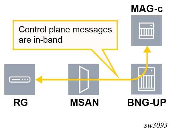
Forwarding between MAG-c and BNG-UP
The forwarding of control plane messages is in-band and sent using an IBCP tunnel.
IBCP
In-band control plane (IBCP) packets are sent by a residential gateway over the data path to the BNG-UP, but must be handled by the MAG-c. Examples include DHCP, DHCPv6, and ICMPv6 RS.
This contrasts for example with out-of-band NAS signaling in case of fixed wireless access (FWA) sessions which do not reach the BNG-UP, but are sent to the MAG-c through an MME (4G) or AMF (5G).
IBCP packets for fixed access sessions arrive before any session state is created. The BNG-UP sends the initial control plane packets over GTP-U to the MAG-c.
Immediately after the PFCP association is created, the MAG-c signals at least one GTP-U tunnel using a dedicated PFCP session for unknown in-band control plane packets. That tunnel is called the default IBCP tunnel.
After handling the initial control plane message, the MAG-c instructs the BNG-UP to forward any subsequent control plane packets over a per-session GTP-U tunnel. The per-session GTP-U tunnel is signaled as part of the regular PFCP session for that connection.
The default IBCP tunnel is only used for packets from the BNG-UP to the MAG-c, return packets use a dedicated per-session GTP-U tunnel.
GTP-U runs over UDP, using port 2152, and is defined in 3GPP TS 29.281. GTP-U is extended to allow transport of Ethernet packets. This is not explicitly added in the GTP-U encoding, rather the content type is defined at tunnel setup in PFCP.
The following table describes the format of the basic GTP-U header for IBCP packets on the CPRi interface between the BNG-UP and the MAG-c.
| Bits | ||||||||
|---|---|---|---|---|---|---|---|---|
| Octets | 8 | 7 | 6 | 5 | 4 | 3 | 2 | 1 |
| 1 | Version=1 | PT=0 | 0 | E | S=0 | PN=0 | ||
| 2 | Message Type = 255 | |||||||
| 3 | Message Length (1st Octet) | |||||||
| 4 | Message Length (2nd Octet) | |||||||
| 5 to 8 | TEID | |||||||
| 9 | Next Extension Header Type 1 | |||||||
- PT indicates the protocol type. The protocol type is 0 for IBCP messages on the CPRi interface.
- E indicates the presence of a meaningful value in the Next Extension Header field. When it is set to 0, the Next Extension Header field either is not present or, if present, is not interpreted. When it is set to 1, the Next Extension Header field is present, and is interpreted.
- S indicates whether the SEID field is present. IBCP messages on the CPRi interface do not contain a session ID.
- PN indicates the presence of a meaningful value in the N-PDU Number field. PN is 0 for IBCP packets on the CPRi interface. The N-PDU number is not used.
- Message Type indicates the type of the message and determines the content of the message beyond the header.
- Message Length is the total length of the packet.
- TEID is signaled during PFCP session establishment for the IBCP packets.
- Next Extension Header Type is only evaluated when E is set to 1. It defines the type of the extension header that follows this field in the GTP PDU.
Default IBCP session
After a PFCP association is created, the MAG-c signals at least one GTP-U tunnel using a PFCP session for unknown IBCP packets. That tunnel is called the default IBCP tunnel
The MAG-c installs basic PDRs for the default IBCP session using PFCP. The BNG-UP uses the SDF filters and Ethernet packet filters in the PDR to filter out control plane traffic packets; for example, to only allow PPPoE or DHCP packets. The FAR that is linked to the PDR defines the GTP-U encapsulation between the BNG-UP and the MAG-c.
The default IBCP session is only relevant to fixed access sessions. For Fixed Wireless Access (FWA) sessions, initial setup is always done out of band and creates a dedicated PFCP session. Subsequent in-band control plane messages can use the IBCP associated with that dedicated PFCP session.
| PDR | PDI | FAR |
|---|---|---|
| PDR 1 UP to CP |
|
FAR
1 |
GTP-U encapsulation and decapsulation
The BNG-UP encapsulates a received control plane packet from the access side in a GTP-U tunnel, using the TEIDs as signaled during the PFCP session setup procedure. The BNG-UP passes the received Ethernet frame as payload in GTP-U, unmodified (that is, including VLAN tags).
The following figure shows the protocol stack for IBCP over the CPRi interface.

- an opaque logical port; for example, the physical port, also known as the Layer 2 Access ID on the Nokia MAG-c
- the local MAC address on the BNG-UP, belonging to the Layer 2 Access ID
The MAG-c sets up a PFCP session using the logical port in the PDR/FAR and uses the MAC address as source MAC when sending control plane messages. Control plane packets matching these dedicated sessions do not use NSH.
See BBF TR-459 for a description of the NSH header and metadata fields.