Fixed Wireless Access sessions
FWA sessions obtain network connectivity through a mobile RAN such as (e-)UTRAN (4G) or NR (5G). FWA sessions use the same BNG-UP, charging, authentication, and address management methods (including ODSA) as fixed BNG sessions.
Introduction to FWA sessions and terminology
FWA sessions obtain network connectivity through a mobile RAN, for example 4G (e-)UTRAN or 5G NR, and therefore they have the following important differences from fixed access sessions.
- FWA sessions perform the initial setup out-of-band and signal directly to the MAG-c, which acts as a PGW-C, SGW-C + PGW-C, or a session management function (SMF), whichever is applicable.
- FWA sessions have tunneled IP connectivity from the client device to the FWA-UP, which acts as a 4G PGW-U, 4G SGW-U + PGW-U, or 5G UPF, whichever is applicable.
FWA sessions are BNG subscriptions, which means they have the same service requirements as fixed sessions. QoS, service selection, pool management, and charging are all applicable to FWA sessions.
FWA sessions often use mobile-specific terminology. The following lists the most common terms and how they map to an FWA deployment.
- APN
- An Access Point Name (APN) identifies a specific PDN but can also be used to
identify a specific gateway within a PDN, or even a specific service type within
a PDN. A single UE can be connected to multiple APNs. Each such session is
called a PDN session. This model maps directly to FWA and is also common with
fixed BNG sessions. An APN consists of the following two sub-fields.
- Network Identifier (NI): defines the network (PDN).
- Operator Identifier (OI): defines the operator’s mobile network in which the PDN gateway resides. This consists of the operator’s MNC and MCC. This field is optional.
- DNN
-
A Data Network Name (DNN) is the 5G equivalent to an APN.
- GPSI
-
Similar to SUPI, the Generic Public Subscription Identifier (GPSI) is introduced in 5G to contain public identifiers such as MSISDN and is also ready to support other type of identifiers. For FWA, the GPSI always contains an MSISDN.
- IMEI
- An International Mobile Equipment Identity (IMEI) is a unique identifier for the hardware device used for the connection. Part of the IMEI is the Type Allocation Code (TAC) which is allocated to a specific device model.
- IMSI
- An International Mobile Subscriber Identity (IMSI) is a globally unique number
identifying the subscriber. For FWA, the IMSI is mapped to a subscriber ID. Its
value consists of the following three sub-fields.
- Mobile Country Code (MCC): uniquely identifies a country
- Mobile Network Code (MNC): uniquely identifies a mobile network within the country
- Mobile Subscriber Identification Number (MSIN): a second globally unique number identifying the subscriber
- MSISDN
- For mobile subscriptions, the Mobile Station International Subscriber Directory Number (MSISDN) is the public and well-known phone number. For FWA sessions, it can be used as an identifier for compatibility with AAA systems that are mostly MSISDN based.
- NSSAI
- Network Slice Selection Assistance Information (NSSAI) is a set of S-NSSAIs that is applicable to a UE. A UE can connect to a single S-NSSAI or to multiple S-NSSAIs.
- PDN
- A Packet Data Network (PDN) is a network the subscriber connects to; for example, the public Internet.
- PEI
- A Permanent Equipment Identifier (PEI) is introduced in 5G that can contain an IMEI and is also ready to support other type of identifiers. For FWA, the PEI always contains an IMEI.
- RAB
- A Radio Access Bearer (RAB) is a radio channel between a UE and the RAN. Multiple RABs per PDN session can exist.
- RAN
- The Radio Access Network (RAN) is antennas providing wireless connectivity.
- S-NSSAI
- Single Network Slice Selection Assistance Information (S-NSSAI) identifies a single network slice, which is a group of mobile functions such as SMF, UPF, and PCF that together provide specific capabilities and characteristics. For example, an FWA slice may contain all FWA UPFs and SMFs, as well as the necessary supporting functions such as CHF or PCF.
- SUPI
-
A global unique Subscription Permanent Identifier (SUPI) is introduced in 5G that can contain an IMSI and is also ready to support other type of identifiers. For FWA the SUPI always contains an IMSI.
- UE
- The User Equipment (UE) is an end device used by the subscriber. The UE and RG can be integrated in one device or can be two separate devices.
Residential Gateway models
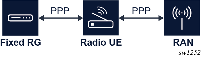
For FWA, there are two common models for a RG.
- An integrated model where the RG provides classic BNG RG functions and acts as a mobile UE. A single IP address can be used to manage this entity. The RG or UE authentication is based on mobile SIM authentication.
- A separate model where there is a logical RG function and a logical UE function. The MAG-c abstracts from how these functions are connected. Often both functions require their own address for management purposes. It is possible to do additional RG device authentication based on PAP/CHAP.
- An integrated RG and UE can have a separate outdoor unit for radio signaling and therefore, can consist of two hardware components.
- A separate model can be a single hardware device that implements the RG and UE function separately with an internal link.
The following figure shows a model using a PPP link between the RG and the UE.
Selected and real APN
configure mobile-gateway pdn apn fixed-wireless-accessAfter initial authentication, a new APN can be returned. This APN is known as the selected APN or the virtual APN. It determines the service selection for the FWA session. If no new APN is returned, the selected service is based on the real APN.
- real
The real, unmodified APN is used as is, including the OI if it was signaled. For example, the received APN equals
internet.mnc001.mcc001.gprsand is used as is. - real-ni-only
The real APN is used, but without the OI part if it was signaled. For example, the received APN equals
internet.mnc001.mcc001.gprsand is used asinternet. - selected
This is the default option. The selected APN is used as is. If no selected APN is available, the system falls back to the real-ni-only option.
| Use case | Context |
|---|---|
|
Use the APN as a match criterion in the ADB. The APN format only applies if the attribute parameter in the match command equals apn. |
|
|
Reflect the APN in the Called-Station-Id attribute for RADIUS authentication. The APN format also applies to the username, if the user-name-format fixed-wireless-access format command in the same context is configured to include the APN. Note: If the mobile UE sends a PPP username as
a PCO during session setup signaling, the username is reflected
as is. The apn-format command in this context
does not modify the username even if it contains an APN.
|
|
|
Reflect the APN in the Called-Station-Id attribute for RADIUS accounting. Note: The user-name attribute from the
authentication is reflected as is in RADIUS accounting. The
apn-format command in this context does
not modify the username in accounting even if it contains an
APN.
|
|
Session identification, subscriber identification, and multi-APN support
For FWA sessions, the MAG-c subscriber key is the IMSI and the FWA session key is the pair (IMSI, APN). So multiple FWA sessions can be set up for the same UE/RG if those sessions use a different APN. This is called multi-APN support. The following lists some use cases of how multi-APN can be used.
- Have a different APN for Internet, video, and voice services.
- Have a different APN for public Internet and private work-from-home VPN connections.
- Have a different APN for a UE management IP address in case of the separated UE/RG model.
Each session can be mapped to a different L3 service and a different FWA-UP. For example, to optimize the BNG-UP resource usage, a low-throughput management-only session can be installed on a different FWA-UP than a high-throughput Internet session.
FWA-UP selection
- Define a UP peer list using the up-peer-list command in the
following context.
configure mobile-gateway profile pfcp - Configure all FWA-UPs as peer in the UP peer list using the peer command in the
following context.
The IP address to use as parameter in the peer command is the source IP address of the PFCP association of the FWA-UP.configure mobile-gateway profile pfcp up-peer-list - Set the FWA-UP selection to true for each peer using the
upf-selection command in the following
context.
configure mobile-gateway profile pfcp up-peer-list peer - Configure the APNs that are supported on the peer using the
apn command in the following
context.
configure mobile-gateway profile pfcp up-peer-list peer - Make a reference to the configured UP peer list using the up-peer-list command in the configure mobile-gateway pdn context.
configure mobile-gateway profile pfcp up-peer-list peerWhen a session is set up, it automatically selects a peer from the UP peer list that is enabled for that APN. Load-balancing over the FWA-UPs is done in a round-robin fashion.
Address signaling methods and deferred allocation
The 3GPP specifications define two methods to signal an allocated IPv4 address:
- directly in NAS messaging during session setup
From MAG-c point of view, the address is included in the session setup messages; for example, in the GTP Create Session Response message.
- via DHCP
The IPv4 address is signaled after the session setup completes.
Which method is used depends on the following parameters, in order of precedence. Each parameter can be absent, or can have the value NAS or DHCP:
- the RADIUS Alc-FWA-IPv4-Signaling-Method VSA
- the configuration of the ipv4-signaling-method command in the
following
context
configure mobile-gateway profile authentication-database entry fixed-wireless-access - the 00AH (IP address allocation via NAS signaling) and the 000BH (IPv4 address allocation via DHCPv4) PCOs as signaled by the UE. If only one is present, that method is used.
- the configuration of the default-ipv4-signaling-method command in
the following context of the selected APN where the session is
created
configure mobile-gateway pdn apn fixed-wireless-access - NAS, by default
If IPv6 is enabled, a UE/RG interface-identifier is derived from the link-local address of the MAG-c. This interface-identifier is signaled via NAS to the UE/RG, which derives a link-local address from it when needed; for example, to send ICMPv6 RS messages.
IPv6 global addresses always use deferred allocation and are signaled in-band after session setup completion. In case of SLAAC, the UE/RG can optionally use the signaled interface-identifier to construct a global address.
For FWA, deferred allocation can be used to assign an address to an RG function in the separated UE/RG model. In this case, the UE can forward the relevant DHCP, DHCPv6, or ICMPv6 messages to the RG without maintaining the stack itself.
QoS
FWA sessions support the generic BNG QoS functionality and are additionally subject to specific mobile QoS constructs. This topic gives a high-level overview of how mobile QoS works. For information about the specific subset that is supported for FWA, see 4G QoS attributes.
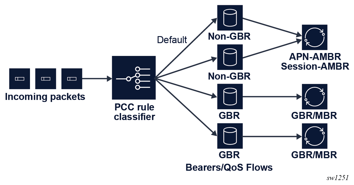
In mobile networks, the concept of a bearer (4G), or a QoS flow (5G), defines the QoS. At least one default bearer or QoS flow exists to which all traffic is mapped by default. More dedicated bearers and QoS flows can be created to which specific traffic is mapped using PCC rules.
Each bearer or QoS flow is classified as either GBR or non-GBR, and QoS treatment on the BNG-UP is applied accordingly. The specified rate values are sent to the BNG-UP using PFCP QER IEs.
- GBR bearer or QoS flow: a GBR and an MBR value are applied.
- Non-GBR bearer or QoS flow: a common MBR is applied to all bearers or QoS flows of this session. For 4G, this value is known as the APN-AMBR, for 5G this value is known as the session AMBR.
The following figure shows a high-level example of QoS handling. It shows a setup with four bearers or QoS flows, of which two are GBR and two are non-GBR (including the default).
Each bearer or QoS flow has QCI (4G), 5QI (5G), and ARP (4G/5G) values. The RAN uses these values, which are transparent to the MAG-c and the FWA-UP, with the exception of the GBR or non-GBR determination of the bearer or QoS flow.
- For 4G, standardized QCI values and the corresponding GBR or non-GBR classification are specified in 3GPP TS 23.203 section 6.1.7.2.
- For 5G, standardized 5QI values and the corresponding GBR or non-GBR classification are specified in 3GPP TS 23.501 section 5.7.4.
- Both QCI and 5QI can be operator-specific, and in this case GBR or non-GBR classification is provisioned together with the QCI or 5QI provisioning. The operator-specific range is from 128 to 254 as defined in 3GGP TS 24.301 section 9.9.4.3 (4G) and 3GPP TS 24.501 section 9.11.4.12 (5G).
The access technology defines how the system learns the different values.
PAP/CHAP authentication
A mobile UE can send PAP/CHAP authentication credentials as a PCO option during the session setup signaling. When such a PCO option is received, the MAG-c uses these credentials in the authentication instead of the locally configured credentials.
- The PAP/CHAP username can be used for the relevant ADB match criteria. For RADIUS
authentication, the username has precedence over the configuration of the
user-name-format fixed-wireless-access format command in the
following
context.
configure mobile-gateway profile bng radius-authentication-profile - The PAP/CHAP credentials are reflected in RADIUS instead of the
password configured in the following
context.
configure mobile-gateway profile bng radius-authentication-profile
PAP/CHAP authentication is typically used for separate RG/UE models, where a PPP link is present between the RG and UE. PAP/CHAP authentication is performed over the link. The UE pretends successful authentication of PAP/CHAP and moves the session to the NCP state. The MAG-c gets a CHAP challenge and a CHAP response in PCOs. In cases where the PAP/CHAP based authentication on the MAG-c fails, the UE tears down the PPP session using the LCP terminate messages.
Session lifetime and held addresses
The session management procedures define the lifetime of an FWA session; for example, a GTP Delete Session Request message. An FWA session can exist without any stack being signaled to the client if deferred allocation is used. Stack timeouts do not drive session deletion. If a session management procedure deletes a session with active IP stacks, those stacks are by default released.
For an integrated RG/UE, this is not a problem because the RG/UE knows of the session failure and knows that IP stacks are lost.
For a separated RG/UE model, the UE can have forwarded those stacks to a RG. Depending on the RG/UE connection model, it is possible that the RG is not aware of the failure and keeps using assigned addresses until their signaled lifetimes expire.
configure mobile-gateway profile authentication-database entry fixed-wireless-accessWhen the hold time is configured, the MAG-c keeps a state for these addresses for the specified hold time. If the ODSA local address assignment allocated the addresses, the ODSA address hold time is automatically increased to the configured hold time. Other than that, there is no link between held addresses and the original allocation source of the addresses (for example, ODSA or AAA). For example, if a held address allocated by ODSA is removed, it is not explicitly released for ODSA. It needs to time out independently.
Held addresses are linked to the FWA session key pair (IMSI, APN). If a new session for the key of an held address is created, the held address is picked up and re-used. The interaction with specific address assignment methods is as follows:
- local address assignment (ODSA)
The new session requests the held address from ODSA. The request cancels any running ODSA hold time and ODSA links the address to the new session. In case ODSA cannot assign the address, the session setup fails; for example, ODSA was not the original allocation source of the held address.
- AAA
The held addresses are ignored and removed in favor of the AAA-signaled address.
Because held addresses do not interact with the original allocation method, Nokia recommends to only enable holding addresses when the address assignment source of a particular session is stable over session creation and deletion. If the address assignment source is not stable, session setups can fail or addresses can be hold for a long time. For example, consider a locally assigned ODSA address being put in the hold state for ten days. If the session is re-established but indicates an AAA address, the held address is not used and not released toward ODSA. The ODSA address keeps its ten day hold time and is not usable during that period.
PDN type selection
FWA sessions need an assigned PDN type, which can be ipv4, ipv6, or ipv4v6. During setup, an initial wanted PDN type is signaled as follows:
- GTP for 4G
- N1 NAS/UDM SDM for 5G
configure mobile-gateway pdn apn pdn-type- If the pdn-type-conversion command is not enabled, or the PDN types are not compatible (for example, IPv4 is signaled and IPv6 is allowed), the session setup fails.
- If the pdn-type-conversion command is enabled and the PDN types are compatible (for example, IPv4v6 is signaled and IPv4 is configured), the FWA session is allowed and a downgrade to a compatible PDN type is performed (for example, IPv4). If a downgrade can happen to both IPv4 and IPv6 (for example, IPv4v6 is signaled and both IPv4 and IPv6 are configured), IPv4 is chosen by default, unless the pdn-type-preferred-IPv6 command is enabled.
To optimize IP address usage, only ODSA addresses that are applicable for the selected PDN type are allocated. For example, if a local IPv4 pool and a local IPv6 PD pool are provisioned, and the PDN type is IPv6, no IPv4 address is allocated.
Similarly, if local or AAA based address assignment allocates addresses for only one stack, the PDN type is downgraded to the type matching that stack if applicable.
mobility and idling
Describes supported FWA mobility and idling procedures
FWA supports the following mobility and idling procedures:
- mobility procedures — X2-based handover (4G) and Xn-based handover (5G)
- idling procedures — S1 release (4G) and AN release (5G)
- reactivation and paging procedures — UE triggered service request (4G+5G) and network triggered service request (4G+5G).
Most of these procedures require interoperability with standard RAN deployments, which assumes these procedures are available by default. Handover procedures provide RAN resiliency when a UE or RG uses them to switch to a new antenna if its current antenna fails.
Most of these procedures require updating the FWA-UP to handle the new traffic rules. This update is done using the following PFCP Session Modification Request messages.
- For mobility procedures, the F-TEID field in the Forwarding Parameter IE is updated.
- For idling procedures, the forwarding rule is removed and replaced by a buffering rule that instructs the FWA-UP to buffer packets. The FWA-UP is also instructed to notify the MAG-c when buffering a packet such that the MAG-c can start paging procedures.
- When completing reactivation procedures, the buffering rule is removed and replaced by a forwarding rule with an F-TEID. Buffered packets are sent to the new F-TEID by the FWA-UP.
Location tracking
The MAG-c tracks and learns the location of an FWA session using procedures such as X2/Xn-based handover, UE-triggered service request, location reporting, and tracking area update. For 4G, the MAG-c requests the MME to report location if the MME signals the "Change Reporting Support Indication" flag and if the BNG charging profile is enabled to track the location. For 5G the MAG-c does not subscribe to specific location updates and only learns location changes as part of other procedures.
When RADIUS location tracking is enabled, an Interim Update message is triggered whenever the user location changes. The user location is sent in the 3GPP-User-Location-Info attribute.
Use the following commands to configure location tracking for RADIUS:
- Use the following command to enable location
tracking.
configure mobile-gateway profile charging bng-charging radius session update-triggers user-location-change - Use the following command to send the user location in the 3GPP-User-Location-Info
attribute.
configure mobile-gateway profile charging bng-charging radius session include-attribute user-location-info
Headless mode for FWA
Headless mode as described in section Headless mode is partially supported for FWA sessions. When the connection between the FWA-UP and the MAG-c fails, the currently installed sessions on the FWA-UP remain unaffected and continue forwarding data.
configure mobile-gateway profile pfcp pfcp-profile path-restoration-time4G and 5G NSA option 3 sessions
Basic FWA network shows the elements involved in a simple FWA network with a MAG-c operating as a combined PGW-C and SGW-C, and a FWA-UP operating as a combined PGW-U and SGW-U. The following figure shows the communication between the elements with the interface name if applicable and for the BNG relevant interfaces, the protocol being used. The high-level role of the MME, SGW, and PGW elements is as follows:
- MME
The MME orchestrates the basic connectivity of the UE and how this connectivity evolves during the lifetime of a session (for example, mobility, idling, paging).
- SGW
The SGW provides advanced data forwarding functionality such as buffering packets for idling UEs or providing a mobility anchor for inter-eNodeB mobility. Often this functionality is combined with a PGW in a single network element. In a CUPS environment the SGW is split in an SGW-C and an SGW-U element.
- PGW
The PGW provides PDN connectivity to an IP network. It can perform additional authorization to PDN-specific AAA servers; for example, authorization using the RADIUS protocol. It enforces charging functionality. In a CUPS environment the PGW is split in a PGW-C and a PGW-U element.
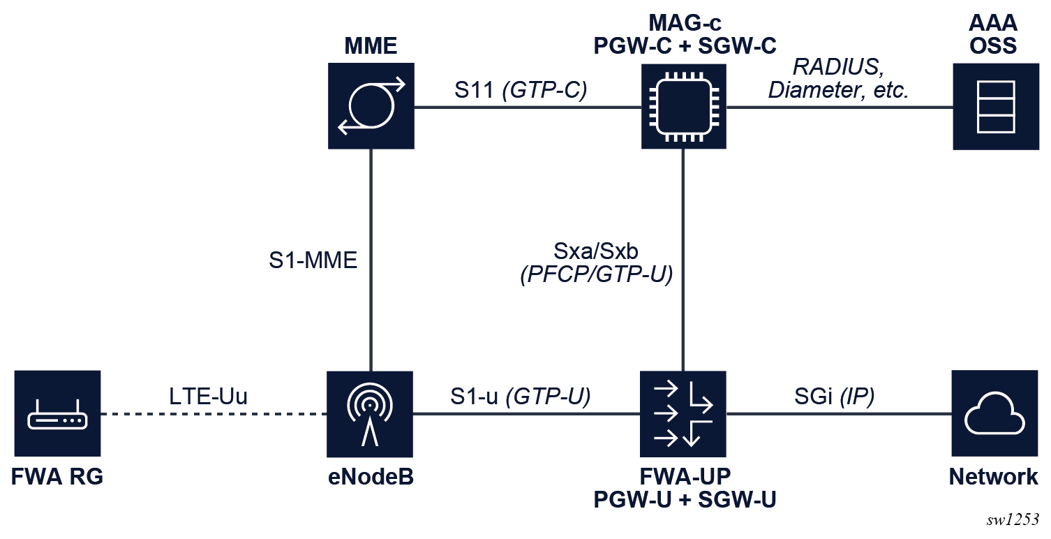
To enable 4G FWA sessions for a combined gateway, the GTP-C S11 and S5 interfaces need to be enabled on the MAG-c. The S5 interface is between the SGW and PGW and is internal for a combined gateway.
- To enable the S5 interface, use the gtp-c command in the
following context.
This interface is not necessarily used to terminate packets, but its IP must match the “PGW S5/S8 Address for Control Plane or PMIP” address that is signaled in the GTP Create Session Request.configure mobile-gateway pdn s5 interface - To enable the S11 interface, use the gtp-c command in the
following context.
This interface transfers the GTP-C packets.configure mobile-gateway pdn s11 interface - To identify the L3 service on the FWA-UP where the GTP-U packets are received, configure the
interface-realm parameter of the
gtp-c command in the following
contexts.
Both realms must be configured the same.configure mobile-gateway pdn s11 interface configure mobile-gateway pdn s5 interface - Configure the EPC node name using the epc-node command in the configure mobile-gateway pdn context. The MCC and MNC value under this node must match the MCC and MNC of the IMSI for new FWA sessions. Otherwise the session is seen as roaming, which is not supported for FWA.
The following figure shows an example of a 4G FWA session setup.
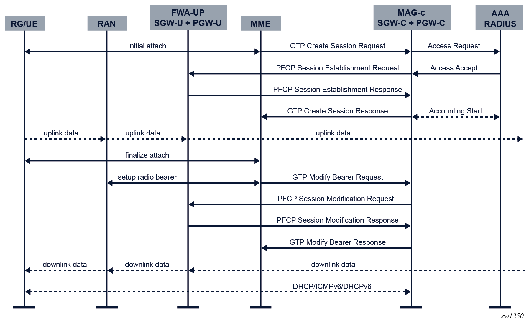
- An initial attach sequence is initiated between the UE and the MME, which leads
to a GTP Create Session Request message toward the MAG-c. This message contains three sets of parameters:
- protocol-specific data to initiate the stateful control session between the MME and the MAG-c
- the required identification and subscription parameters to initiate
session management for the PDN sessionNote: These parameters always include IMSI, IMEI, APN, PDN type, and can be extended with additional values such as MSISDN, static IP addresses, and APN-AMBR.
- PCOs sent from the client; for example, a request for DNS servers, a request for deferred allocation, or PDN-specific authorization using encapsulated PAP/CHAP messages
- Based on the signaled APN, the MAG-c looks up the APN under the following context.
To enable FWA functionality, the APN must be configured with an FWA node in the no shutdown state using the fixed-wireless-access command in the following context.configure mobile-gateway pdn apn
The authentication flow of the FWA node configured using the authentication-flow command in the following context is used to authenticate the session.configure mobile-gateway pdn apn
FWA-specific ADB match criteria or RADIUS include attributes can be used.configure mobile-gateway pdn apn fixed-wireless-access - The MAG-c selects a FWA-UP and sets up a PFCP session. The PFCP session carries the full session data, including all BNG-specific parameters. At this point, the RAN has not yet allocated a downlink GTP-U F-TEID, so the downlink data packet is buffered. For uplink traffic, the FWA-UP allocates an F-TEID and sends it to the MAG-c.
- The MAG-c sends a GTP Create Session Response message to the MME. This message includes the uplink GTP-U F-TEID as allocated by the FWA-UP. It includes the IPv4 address if one was allocated and signaled via NAS. The MME completes the attach toward the UE and sets up the radio bearers toward the RAN. At this point, uplink data traffic can be sent.
- As part of the radio bearer setup, the RAN allocates a downlink GTP-U F-TEID. The MME signals the downlink to the MAG-c using a GTP Modify Bearer Request Message. The MAG-c forwards it to the FWA-UP using a PFCP Session Modification Request message which changes the downlink rules from buffering to forwarding with the provisioned F-TEID. The FWA-UP acknowledges the PFCP message to the MAG-c. The MAG-c acknowledges the GTP message to the MME. At this point, downlink traffic is possible.
- The data layer connectivity is ready, but it is possible that not all IP addresses allocated to the RG are signaled to the UE. The addresses are signaled over the data connection using the DHCP, ICMPv6, and DHCPv6 protocols.
4G QoS attributes
4G FWA sessions only support default bearers and these default bearers must be of the non-GBR type. This means that only an APN-AMBR is supported for mobile-specific rate-limiting.
ARP, QCI, and APN-AMBR for the default bearer are determined using the following parameters, in order of precedence:
- from RADIUS, the 3GPP-GPRS-Negotiated-QoS-Profile attribute
- from the ADB, the QoS profile configured using the
qos-profile command in the following
context
configure mobile-gateway profile authentication-database entry fixed-wireless-accessNote: The QoS profile must reference a profile configured in the following context.configure mobile-gateway profile qos-profile - from the MME/HSS, the parameters in the GTP Create Session Request message
configure mobile-gateway profile bng radius-authentication-profile include-attributeThe final QoS parameters are used for the generic mobile QoS functionality. They are included in the GTP Create Session Response message so the MME can signal their values to the eNodeB and the UE.
The APN-AMBR can be dynamically changed during the session lifetime using the following procedures:
- a CoA including the 3GPP-GPRS-Negotiated-QoS-Profile attribute
- an HSS-initiated QoS procedure, where the new APN-AMBR is sent using a GTP Modify Bearer Command message
Both procedures trigger a forced change of the APN-AMBR on the FWA-UP using a PFCP Session Modification Request that updates the applicable QER IE. When successful, the MAG-c initiates the PGW-initiated QoS update procedure to signal the new APN-AMBR to the MME/HSS using a GTP Update Bearer Request message.
5G standalone sessions
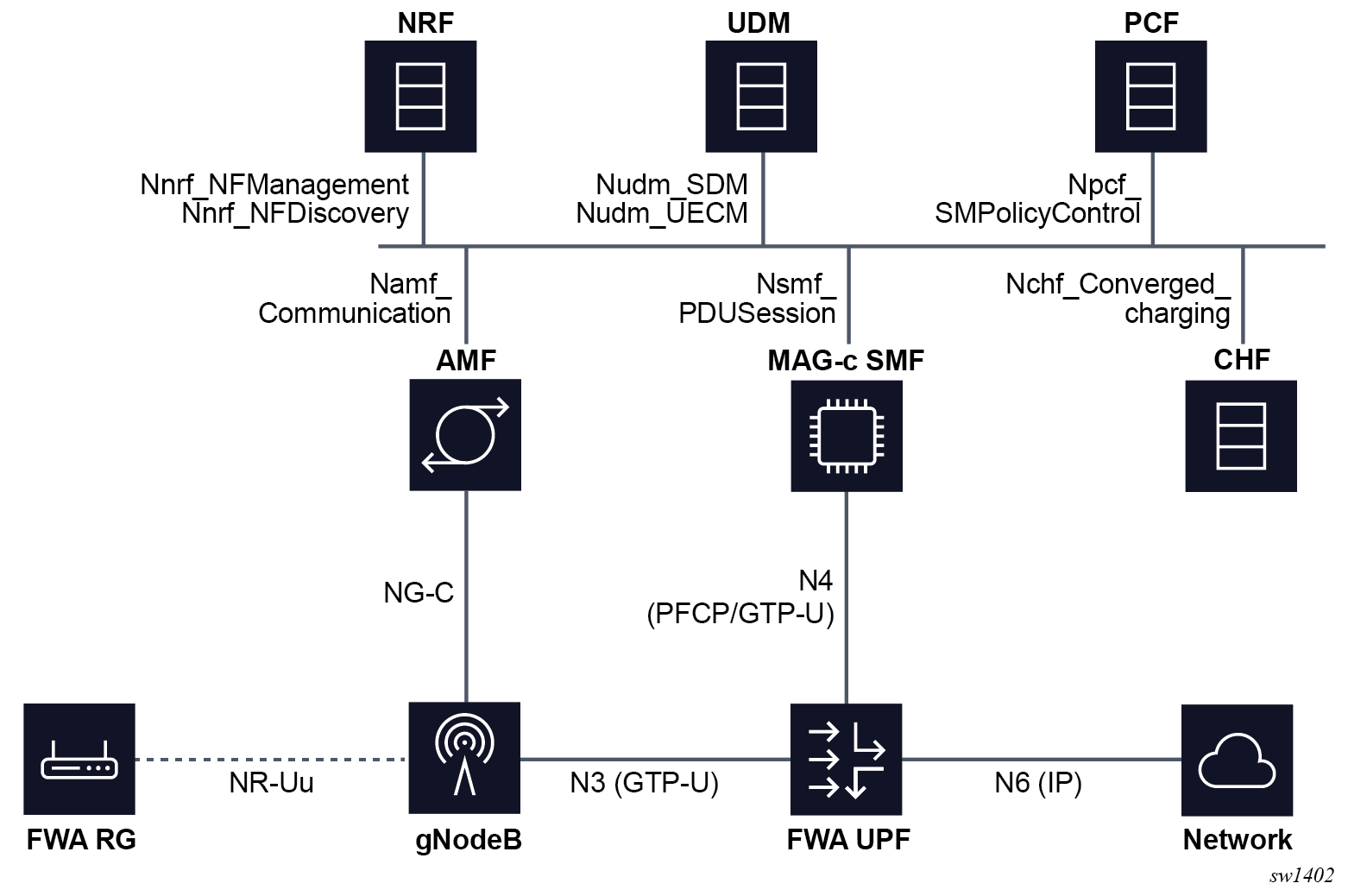
Basic 5G FWA network shows the elements involved in a basic 5G FWA network with a MAG-c operating as an SMF and an FWA-UP operating as a UPF. The figure highlights the direct communication between the interface elements and the protocols used, if applicable. The figure does not include the N1 (NAS signaling from and to the UE) and N2 (RAN control plane) interfaces because these interfaces may terminate on both AMF and SMF depending on the type of control plane signaling.
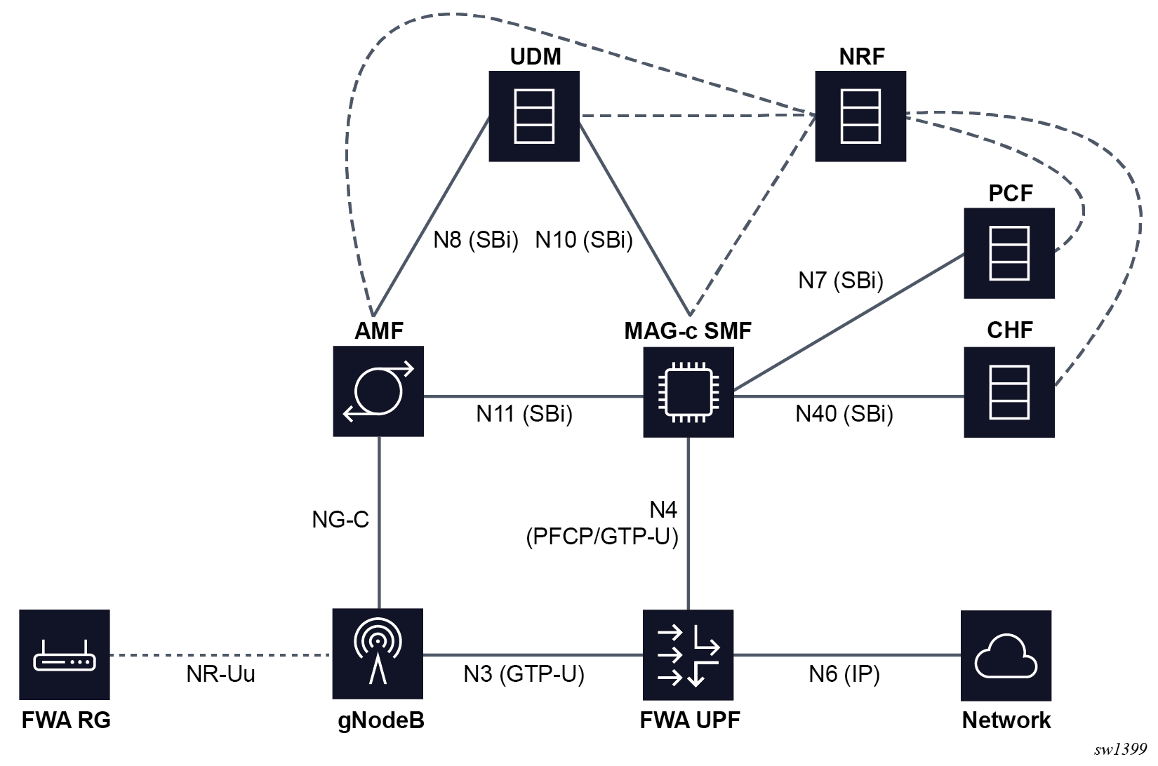
The following are high-level descriptions of the role of each function:
-
AMF
The Access and Mobility Function (AMF) orchestrates the basic connectivity of the UE and how this connectivity evolves during the lifetime of a UE (for example, mobility, idling, and paging).
-
SMF
The Session Management Function (SMF) maintains 5G sessions. It connects to other functions such as AAA, UDM, PCF, and CHF to retrieve and manage subscription, policy (including QoS), and charging data for an active session. The SMF provides a similar function to a combined SGW-C and PGW-C in 4G, however, in contrast to 4G it performs all the signaling for session management directly. For example, the SMF constructs all N1 (NAS) session-management messages for the UE directly, as compared to 4G, which uses the MME to proxy relevant data over GTP to the UE.
-
UDM
The Unified Data Management (UDM) provides subscription data for a user. This subscription data is queried by multiple functions, for example, the AMF retrieves access and mobility subscription data and the SMF retrieves session management subscription data. Additionally, functions such as the SMF register themselves with the UDM to indicate they are an active function for a specific UE or session.
-
NRF
The Network Repository Function (NRF) keeps a repository of all 5G functions. When a function becomes available, for example the SMF, it registers itself with the NRF. Subsequently, other functions such as the AMF can query the NRF to discover the functions with which they need to communicate.
-
PCF
The SMF queries the Policy Control Function (PCF) at setup to retrieve policy information applicable to a session. This policy information can be QoS, ACL, or charging related. Some policy information is directly applied by the SMF, but most is passed to other functions to enforce, such as the UPF, gNodeB, UE, or CHF. The PCF can also request updated policies on some triggers, such as location changes or revalidation timeouts and make direct requests for a policy update without requiring a trigger.
-
CHF
The Charging Function (CHF) is used for both online and offline charging. In both cases CHF manages charging based on Rating Groups (RGs), which can either represent an entire session or a subset of traffic. For offline charging, the CHF requests to signal statistics upon reaching a specific time or volume threshold; however, it does not enforce any limits. For online charging, the CHF additionally enforces quota limits that trigger the SMF and UPF to take immediate action without communicating to the CHF; for example, to stop forwarding for the RG.
-
UPF
The User Plane Function (UPF) provides connectivity to an IP network, enforcing dataplane policies such as QoS and ACLs, reporting statistics, and quotas.
5G session management
Enabling 5G FWA sessions requires configuration of the SMF PDUSession services, the AMF client communication services, and typically the UDM.
SMF PDUSession service server configuration
To enable 5G FWA sessions, do the following:
- Use the following command to configure an SMF PDUSession service server instance on
the MAG-c, to handle service calls from the AMF to the
SMF.
configure mobile-gateway pdn sba-server-services nsmf-pdusession - Configure the service instance with the following required elements:
- an interface on which the MAG-c listens for incoming connections from the AMF
- the N3 interface realm that is sent to the FWA UP as the realm (service) where N3 GTP-u tunnels are terminated
Note: When 4G and 5G interworking is required, configure the interface-realm option for the S11 interface using the following command.configure mobile-gateway pdn s11 interface gtp-cSee 4G and 5G NSA option 3 sessions for more information about configuring the S11 interface.
-
Optionally provision the following for the server instance:
- An HTTP2 profile to influence generic HTTP/2 and SBi parameters; see HTTP/2 , OpenAPI, and Python for more details.
- An API prefix to be part of the service URI; see 5.2.2.1.5.3 URI construction for more information about how URIs are constructed.
- An FQDN to identify the service by other NF peers. For example, the AMF can use this when constructing URIs or when discovering the SMF using DNS.
- Multiple attributes to send to the NRF when registering the service:
- NF domains lists using the following
command.
configure mobile-gateway pdn sba-server-services nsmf-pdusession allowed-nf-domains-list - PLMNS using the following
command.
configure mobile-gateway pdn sba-server-services nsmf-pdusession allowed-plmns - slices using the following
command.
configure mobile-gateway pdn sba-server-services nsmf-pdusession allowed-slicesSee NF registration for more information about how services and related attributes register with the NRF.
- NF domains lists using the following
command.
- Use the following command option to enable the service
instance.
configure mobile-gateway pdn sba-service-realm server-service service-instance
AMF client communication service configuration
In addition to the SMF server instance, you must configure the AMF communication client service. This service generates service calls from the SMF to the AMF, to forward N1 or N2 messages to the UE or RAN.
To configure the AMF client service, do the following:
- Use the following command to configure the AMF
service.
configure mobile-gateway pdn sba-client-services amf-client namf-comm -
Use the following command to configure an interface for the service instance that the MAG-c uses to communicate with the AMF.
configure mobile-gateway pdn sba-client-services amf-client namf-comm interface - Optionally configure the following for the client service instance:
- An FQDN to identify the service by other NF peers. For example, when generating callback functions the SMF can use the FQDN in the URI, rather than the IP address; see URI construction for more information about how URIs are constructed.
- An NF ID list to specify which NF instances can be used for the AMF service; see Local NF ID list-based discovery for more information. This command is required if the AMF is not dynamically discovered using NRF.
- An HTTP2 profile to influence generic HTTP/2 and SBi parameters; see HTTP/2 , OpenAPI, and Python for more information.
- An AMF profile to handle AMF failure handling; see section Failure handling for more information.
- An N1 profile configured using the following command.
configure mobile-gateway profile n1-profileUse the following commands to configure the N1 profile to influence N1 signaling:
- The N1 profile timer governs retransmit behavior for an N1 PDU
SESSION MODIFICATION COMMAND
message.
configure mobile-gateway profile n1-profile n1-t3591 - The N2 profile timer specifies retransmit behavior for an N1 PDU
SESSION RELEASE COMMAND
message.
configure mobile-gateway profile n1-profile n1-t3592 - The cause-code commands in the following context
specify which error codes are signaled to the UE and AMF for several
session removal and rejection
cases.
configure mobile-gateway profile n1-profile
- The N1 profile timer governs retransmit behavior for an N1 PDU
SESSION MODIFICATION COMMAND
message.
- This service generates service calls from SMF to AMF, to forward N1 or N2 messages
to the UE or RAN. Use the following command option to subsequently enable this
service
instance.
configure mobile-gateway pdn sba-service-realm client-service service-instance
UDM function configuration
In 5G, the MAG-c acting as the SMF directly communicates with the UDM function to retrieve session subscription data. This differs from 4G where a similar function is provided by the HSS, but the PGW does not retrieve this context directly. In 4G, the MME retrieves the subscription data from HSS and signals this via GTP messages to the PGW.
UDM SDM client service
To enable UDM-based subscription retrieval, do the following:
- Use the following command to configure a UDM SDM client
service.
configure mobile-gateway pdn sba-client-services udm-client nudm-sdm - Use the following command to configure an interface for the service instance
over which the MAG-c communicates with the
UDM.
configure mobile-gateway pdn sba-client-services udm-client nudm-sdm interface - Configure the following optional parameters:
- An FQDN to identify the service by other NF peers. For example, when generating callback functions the MAG-c can use the FQDN in the URI, instead of the IP address; see URI construction for more information about how URIs are constructed.
- An NF ID list to specify NF instances that can be used for the UDM function; see Local NF ID list-based discovery for more information. This command is required if the UDM is not dynamically discovered using NRF.
- An HTTP2 profile to influence generic HTTP/2 and SBI parameters; see HTTP/2 , OpenAPI, and Python for more information.
- A UDM SDM profile that contains parameters on how to handle UDM failure handling; see Failure handling for more information.
- Use the following command to enable this service instance.
configure mobile-gateway pdn sba-service-realm client-service
UDM UECM client service
The UDM UECM (UE Context Management) service is also used to register the MAG-c as an SMF providing service for the UE. To enable this service:
- Use the following command to configure a UDM UECM client
service.
configure mobile-gateway pdn sba-client-services udm-client nudm-uecm - Use the following command to configure an interface for the service instance
over which the MAG-c will communicate with the
UDM.
configure mobile-gateway pdn sba-client-services udm-client nudm-sdm interface -
Configure the optional parameters as described for the UDM client service; see UDM SDM client service.
- Use the following command to enable this service
instance.
configure mobile-gateway pdn sba-service-realm client-service
FWA session setup for 5G
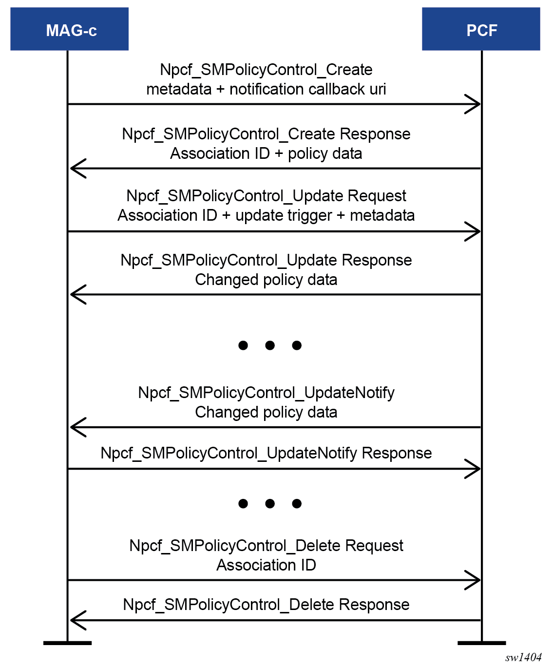
Typically a UDM (see UDM function configuration) and PCF (see PCF-based policy management) are configured for a 5G session, in addition to the SMF PDUsession service and the AMF client communication service. The following figure shows the basic 5G FWA session setup when all these components are configured.
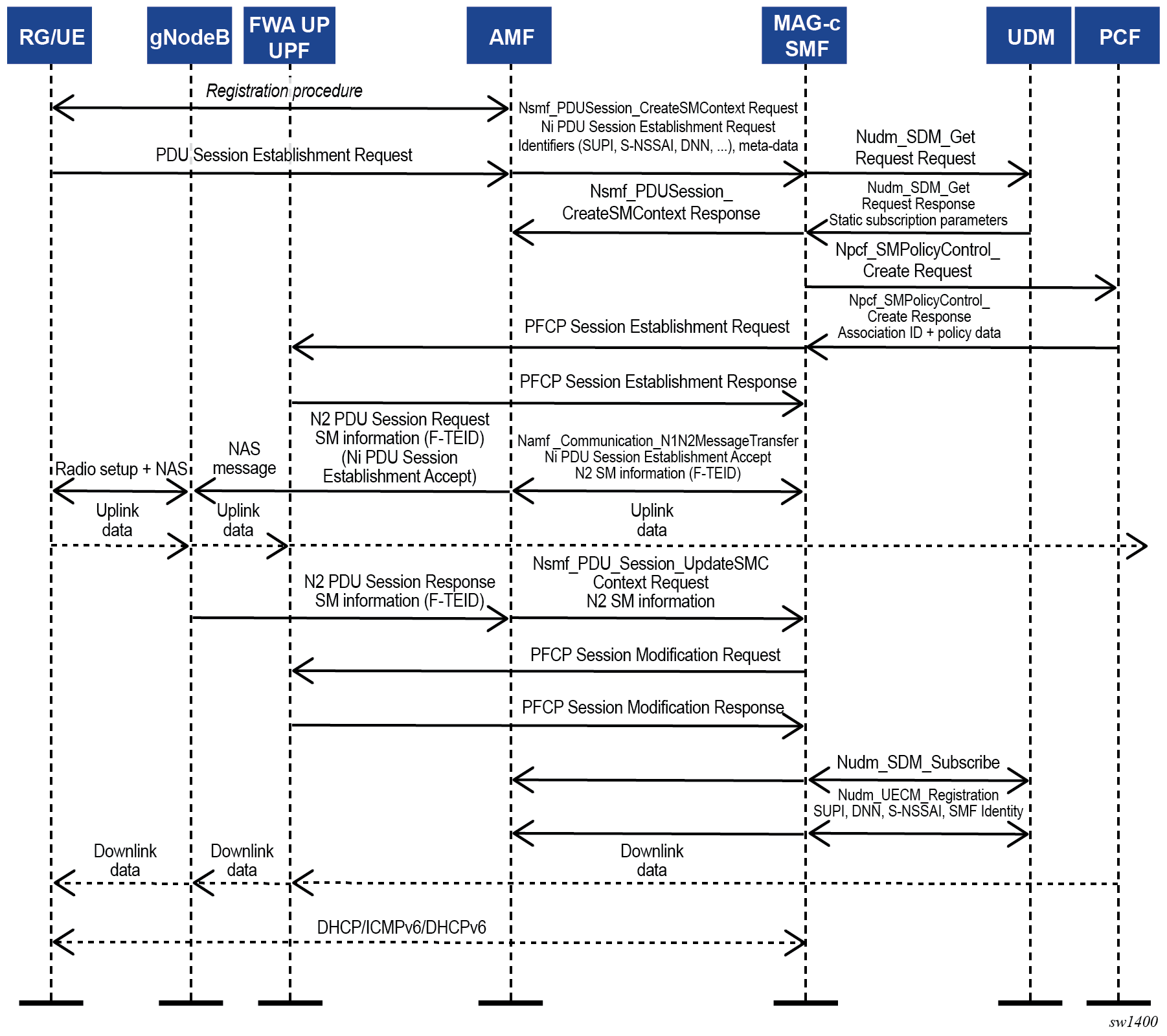
The following describes the message flow and actions to set up a 5G FWA session.
- An initial registration sequence is initiated between the UE and the AMF. This procedure is orthogonal to the SMF because it does not involve any session-management functionality. Upon completion of the registration, an FWA UE requests creation of a PDU session to forward traffic. To do this, it generates a PDU Session Establishment Request NAS message and signals this to the AMF. Upon receipt of this message, the AMF may obtain additional subscription parameters from the UDM and determines which SMF should handle the session based on local configuration. For example, a specific FWA slice (S-NSSAI) could be used, with which the SMF registers (see NF registration) and the AMF discovers this SMF by calling the Nnrf_Discovery service that has the S-NSSAI configured in the query parameters. Upon discovering the SMF, the AMF creates a session management resource on the SMF by calling the Nsmf_PDUSession_CreateSMContextRequest service operation. In this it includes the PDU Session Establishment Request NAS message as it is, and any additional metadata it can provide, for example the DNN.
-
Upon receiving the Nsmf_PDUSession_CreateSMContextRequest the MAG-c uses the signaled DNN to look up the configured APN/DNN in the following context.
configure mobile-gateway pdn apnNote: To enable 5G FWA functionality, the APN must be in the enabled state and configured with an FWA node using the following command.configure mobile-gateway pdn apn fixed-wireless-accessIf a UDM client service is configured (see UDM function configuration ), a Nudm_SDM_Get Request service call is executed to obtain subscription parameters such as session AMBR, default 5QI, default S-NSSAI, and so on.
If the UDM is not configured, these parameters must either be provided by the PDU Session Create message, or locally configured on the MAG-c. Subsequently, the authentication flow of the FWA node (configured using the following command) is used to authenticate the session.
configure mobile-gateway pdn apn authentication-flowFWA-specific ADB match criteria or RADIUS include attributes can be used. Match criteria use data from the PDU Session create call and the UDM. For example, if an S-NSSAI is not provided in the create call, but a default S-NSSAI is provided in UDM subscription data, this is matched.
- After the UDM and authentication flow is completed, the MAG-c answers the call from the AMF Nsmf_PDUSession_CreateSMContext. This creates the session context in the AMF only; it does not yet include an answer to the UE-originated PDU Session Establishment Request message.
- Optionally, after the UDM and authentication flow completes, the MAG-c can obtain policy data from a PCF. See PCF-based policy management for more information about policy management and the PCF service.
- When all authentication and policy management is completed, the MAG-c selects an FWA-UP and sets up the corresponding PFCP session that carries the full session data, including all BNG-specific parameters. The RAN (gNodeB) has not yet allocated a downlink GTP-U F-TEID, so the downlink data packet is buffered. For uplink traffic, the FWA-UP allocates an F-TEID and sends it back to the MAG-c. See the 7750 SR and VSR BNG CUPS User Plane Function Guide for information about the BNG CUPS UPF.
- The MAG-c acknowledges the UE-originated PDU Session Establishment Request message by generating an N1 PDU Session Establishment Accept message. It also generates an N2 SM Information message which is sent to the RAN (gNodeB), including the F-TEID it received from the FWA-UP. Both messages also include any policy QoS rules applicable to either the UE or RAN. It includes these messages in a Namf_Communication MessageTransfer service call toward the AMF. The AMF in turn creates an N2 PDU Session Request call to the RAN to create context on the RAN, including the N2 SM Information and N1 PDU Session Establishment Accept message generated by the SMF. The RAN and UE finalize the radio resources setup. The uplink data can now flow.
- The RAN acknowledges the session context creation using an N2 PDU Session Response message to the AMF. In this message it also includes an N2 SM Information message with its F-TEID for downlink data, which the AMF forwards to the MAG-c using the smf_PDU_Session_UpdateSMContext service. The MAG-c forwards the F-TEID to the FWA-UP using a PFCP Session Modification Request message. This changes the downlink rules from buffering to forwarding with the provisioned F-TEID. The FWA-UP acknowledges the PFCP message to the MAG-c, which in turn acknowledges the smf_PDU_Session_UpdateSMContext call. Downlink traffic is now possible.
- If the UDM is enabled, the MAG-c registers itself for subscription updates for this session context using the Nudm_SDM_Subscription service call. Additionally, it also registers itself as the active SMF for this UE session using the Nudm_UECM_Registration service call.
- The data layer connectivity is now fully ready, although it is possible that not all IP addresses allocated to the RG are signaled to the UE. The addresses are signaled over the data connection using the DHCP, ICMPv6, and DHCPv6 protocols as needed. See Address signaling methods and deferred allocation for more information.
5G QoS function
The following parameters in order of precedence determine the default ARP, 5QI, and session-AMBR for the default bearer:
- from the PCF, the authSessAmbr and authDefQos information elements
- from RADIUS, the 3GPP-GPRS-Negotiated-QoS-Profile attribute
- from the ADB, the QoS profile configured using the following
command:
configure mobile-gateway profile adb entry fixed-wireless-access qos-5g-profileNote: The QoS profile must reference a profile configured in the following context.configure mobile-gateway profile qos-5g-profile - from the UDM, the 5G QoS profile and sessionAmbr information elements
configure mobile-gateway profile qfi-mapping-profile 5qi-as-qfi configure mobile-gateway pdn qfi-mapping-profile
configure mobile-gateway pdn apn qfi-mapping-profile- It is not allowed to modify the 5QI for a QoS flow mid-session. This includes the default 5QI for the default QoS flow.
- It is not possible to use standard or vendor-specific 5QI values above 64.
When QoS flows are created, the MAG-c acting as the SMF signals the QoS flows and the corresponding parameters to the RAN (gNodeB), UPF, and the UE. Toward the RAN and UE this includes parameters that are typically not applicable to SMF or UPF and are passed through as they are; for example, averaging window.
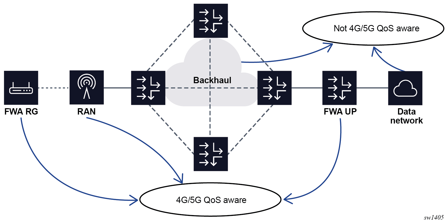
DSCP marking
In addition to applying base 4G and 5G QoS, Nokia’s FWA solution can also apply DSCP marking based on QCI/5QI and ARP values. The FWA UP remarks the DSCP values as follows:
- In the uplink direction, the FWA UP remarks the DSCP value of the forwarded IPv4 and IPv6 PDU packets. This is useful for QoS treatment based on QCI/5QI in the data network beyond the FWA UP.
- In the downlink direction, the FWA UP remarks the DSCP value of both the forwarded IPv4 and IPv6 PDU packets and marks the DSCP value of the outer GTP-u header. This is useful to honor 4G/5G QoS properties in the aggregation network between UP and RAN.
As shown in the following figure, in both directions statically preprovisioned QoS treatment is applied based on QCI/5QI and ARP via the DSCP values in Network Elements (NEs) that are typically not 4G or 5G QoS aware.
Do the following to apply DSCP marking on the UP:
- Use the following command to configure a QCI
policy.
configure mobile-gateway profile policy-options qci-policy - Use the following commands to configure per QCI and ARP combination, the DSCP value
in the uplink (in) and downlink (out)
directions and to disable DSCP
preserve.
configure mobile-gateway profile policy-options qci-policy qci configure mobile-gateway profile policy-options qci-policy qci dscp configure mobile-gateway profile policy-options qci-policy qci dscp-preserve - Apply the QCI policy in the following
context.
configure mobile-gateway pdn apn qci-policy
5G slicing
In 5G networks, a slice identifies an end-to-end logical network, from the UE to the network, on top of the shared physical infrastructure. The user can pick the physical or virtual components on a per-slice basis. This is a very flexible and powerful concept that can be used for many purposes. For example, FWA can be expressed as a single slice with dedicated FWA SMF and FWA UPF components.
MAG-c acting as the SMF is not involved in the slice-selection function itself. However, when selecting a peering NF instance via NRF, the MAG-c can use S-NSSAI as a query parameter to discover only peers associated with the selected slice. The MAG-c also passes the S-NSSAI to any peers, such as the UDM, PCF, or CHF, which require the MAG-c S-NSSAI to identify the services to offer. Finally, the SST and SD part of the S-NSSAI can be used as a match parameter in the authentication database, which allows the S-NSSAI to influence a wide set of parameters on the itself.
5G service-based interfaces
This section provides basic information about Service Based interfaces (SBi), where each interface (such as N11) consists of one or more services.
Introduction to Service Based Architecture
The 5G core network is a Service Based Architecture (SBA), which consists of multiple Network Functions (NFs) communicating using a common Service Based Protocol. This protocol is based on OpenAPI v3 using JSON signaled over HTTP/2. Multiple instances of Network Functions can exist (for example, multiple SMFs) and each instance is identified by a Network Function Instance ID (NFInstanceID), which is modelled as a Unique Universal Identifier (UUID).
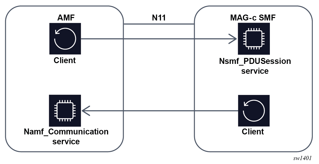
Communication between functions is based on services offered by each function. Each service consists of a service producer (server) and a service consumer (client). Each service is typically oriented at executing a very specific function. An interface can consist of multiple services, as shown in Relationship between service and interface for the N11 interface. The N11 interface consists of at least the Nsmf_PDUSession service where the SMF acts as server, and the Namf_Communication service where the AMF acts as server. This concept is called Service Based interfaces (SBi), where each interface (such as N11) consists of one or more services. Services can be reused over interfaces; for example, the Nudm_SDM service is used both on the N8 interface by AMF and N10 interface by SMF.
In general, any consumer can consume a service, subject to access control. This allows for easy extensibility and re-use. Examples of this are the Nnrf_NFDiscovery and Nnrf_NFManagement services, both of which are served by the NRF. These services are used by other NFs to discover other NFs and register themselves for discovery respectively. For this reason, a 5G core architecture is often presented in an alternative form where the focus is not on interfaces such as shown in Basic 5G FWA network but on the provided services. An example of such a representation is shown Basic 5G network with service representation. This representation also makes it clear that the Service Based Architecture is focused on the control plane functions.
NF peer discovery
When acting as a client, the MAG-c performs the following steps to establish a peer to host the NF service:
- Discover the list of NF instances identified by UUIDs and select one NF instance:
- The NF instance with highest priority is usually selected. Note: A lower priority value means a higher priority.
- When multiple NF instances have the same priority, the UPF does hash-based selection per session.
- In some cases, a specific UUID may already be signaled and picked from the list of discovered instances, ignoring the priority. For example, the AMF signals in the Nsmf_PDUSession operations the AMF UUID to use for the related Namf_communication service.
- The NF instance with highest priority is usually selected.
- Determine a list of IP addresses associated with the selected NF instance and select one IP address to use.
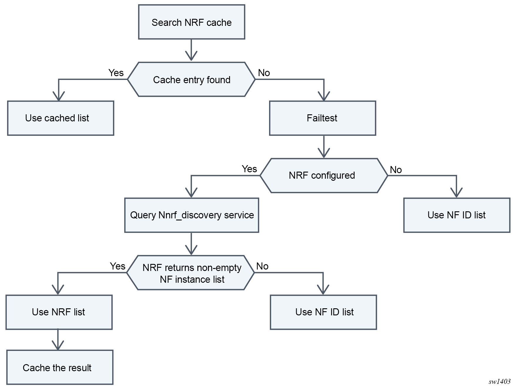
For the discovery of NF instances, the MAG-c supports both NRF-based discovery using the Nnrf_NFDiscovery service (see NRF-based discovery for more information) and a locally configured NF ID list (see Local NF ID list-based discovery for more information). When configured, NRF-based discovery has precedence and the NF ID list is only used if the NRF lookup fails or does not return any NF instances. The following figure shows the NF instance discovery.
NRF-based discovery
To enable NRF-based discovery, do the following:
- Use the following command to configure a client service
instance.
configure mobile-gateway pdn sba-client-services nnrf-disc - Within the NNRF client service configure the following:
- Use the following command to specify the interface MAG-c uses to communicate
with the
NRF.
configure mobile-gateway pdn sba-client-services nrf-client nnrf-disc interface - Use the following command to specify that NF instances that can be used for
the discovery service; see Local NF ID list-based discovery
for more
information.
configure mobile-gateway pdn sba-client-services nrf-client nnrf-disc nf-id-list
- Use the following command to specify the interface MAG-c uses to communicate
with the
NRF.
-
Provision an optional HTTP/2 profile to change generic HTTP/2 and SBi functionality, such as HTTP/2 level retries or enable Python. See HTTP/2 , OpenAPI, and Python for more information.
- Use the following command option to enable the client service instance in the
following
context.
configure mobile-gateway pdn sba-service-realm client-service
When NRF discovery is provisioned, it is automatically enabled for AMF, CHF, PCF, and UDM. Use the following command to suppress discovery for any of these functions.
configure mobile-gateway pdn sba-client-services nrf-client nnrf-disc suppress-discoveryThe following query options are included when discovering PCF, CHF, or UDM as follows:
- S-NSSAI
S-NSSAI is included by default for all, however, you can use one of the following commands to disable it.
configure mobile-gateway pdn sba-client-services nrf-client nnrf-disc exclude-snssais configure mobile-gateway pdn apn pcf-selection exclude-snssais - SUPI
SUPI is included by default, however, you can disable it for each function using the following commands:
- for the
UDM
configure mobile-gateway pdn sba-client-services nrf-client nnrf-disc udm-selection-options exclude-supi - for the CHF
-
configure mobile-gateway pdn sba-client-services nrf-client nnrf-disc udm-selection-options exclude-supi - for the PCF
-
configure mobile-gateway pdn apn pcf-selection exclude-supi
- for the
UDM
- preferred-locality
This option is included if the following commands are configured.
configure mobile-gateway pdn sba-client-services nrf-client nnrf-disc use-locality configure mobile-gateway pdn nf-profile-attributes locality - GPSI
GPSI is included by default for PCF and CHF discovery. You can disable it using the following commands:
- for the
CHF
configure mobile-gateway pdn sba-client-services nrf-client nnrf-disc chf-selection-optionsexclude-gpsi - for the
PCF
configure mobile-gateway pdn apn pcf-selection exclude-gpsi
- for the
CHF
- DNN
DNN is included by default for the PCF.
-
Serving scope
This option is included by default for the PCF.
The NRF keeps a cache of discovered NF instances per query. This cache expires based on the validityPeriod IE returned from the NRF. Use the following command to override this value.
configure mobile-gateway pdn sba-client-services nrf-client nnrf-disc nrf-cache-intervalWhen a valid cache entry is discovered, it is used instead of contacting the NRF. When an NRF cannot be reached or returns an error, it is temporarily blocked for discovery. See NRF-based discovery for more information.
Local NF ID list-based discovery
To configure an NF ID list to be used for local discovery, do the following:
- Use the commands in the following context to configure an NF ID list with multiple
NF profile ID entries, each identifying an NF Instance and its profile.
configure mobile-gateway profile list nf-id-list nf-prof-idConfigure the following per NF instance:
- Use the following command to configure a mandatory UUID that is used to
globally identify the NF
Instance.
configure mobile-gateway profile list nf-id-list nf-prof-id uuid - Use the following command to configure an FQDN that is used to retrieve a
list of IP addresses using a DNS client as described in section
5.2.2.1.5.2.3. This command, the prioritized-address-list command, or both
commands must be
configured.
configure mobile-gateway profile list nf-id-list nf-prof-id fqdn - Use the following command to configure a prioritized address list that is
used to directly determine a list of IP addresses. Either this command, the
fqdn command, or both commands must be
configured.
configure mobile-gateway profile list nf-id-list nf-prof-id prioritized-address-list - Use the following command to configure an NF priority that is used to
determine the priority of this NF Instance compared to other NF instances. A
lower value means higher
priority.
configure mobile-gateway profile list nf-id-list nf-prof-id nf-priority - Use the following command to configure a custom API prefix that is used to
insert in the URI of service calls as specified in TS
29.501.
configure mobile-gateway profile list nf-id-list nf-prof-id api-prefix - Use the following command to activate this NF instance for selection. This
requires the UUID and at least one of the FQDN or prioritized address list
to be
configured.
configure mobile-gateway profile list nf-id-list nf-prof-id enable
- Use the following command to configure a mandatory UUID that is used to
globally identify the NF
Instance.
- To use the NF ID list for NF discovery, configure the nf-id-list
command for any of the following services:Note: If NRF-based discovery is also enabled for a service, this takes precedence over the NF ID list configuration. However, the NF ID list may still be useful either as a fallback or for cases where NRF returns a UUID but not an FQDN or IP address. See NF peer discovery and NRF-based discovery for more information.
- Nnrf_NFDiscovery
service
configure mobile-gateway pdn sba-client-services nrf-client nnrf-disc nf-id-listNote: This service does not support NRF-based discovery. - Nnrf_NFManagement
service
configure mobile-gateway pdn sba-client-services nrf-client nnrf-nfm nf-id-listNote: This service does not support NRF-based discovery. - Namf_Communication
service
configure mobile-gateway pdn sba-client-services amf-client namf-comm nf-id-list - Nudm_SDM service:
configure mobile-gateway pdn sba-client-services amf-client nudm-sdm nf-id-list - Nudm_UECM service:
configure mobile-gateway pdn sba-client-services udm-client nudm-uecm nf-id-list - Npcf_SMPolicyControl service:
configure mobile-gateway pdn apn pcf-selection nf-id-list - Nchf_ConvergedCharging
service
configure mobile-gateway profile charging bng-charging chf chf-selection nf-id-list
- Nnrf_NFDiscovery
service
DNS-based IP lookup
To enable DNS-based lookup, do the following:
- Use the following command to configure a DNS
profile.
configure mobile-gateway profile dns-profileThe following parameters can be configured for the DNS profile:
-
IP DSCP and IP TTL
These parameters determine the DSCP and TTL values in the IP headers of outgoing DNS request packets.
Message retransmit
This parameter determines how often and how quickly an unanswered DNS request is retransmitted.Primary, secondary, and tertiary DNS
These parameters determine the DNS servers to attempt. At least a primary DNS must be configured.
-
-
Use the following command to apply the configured DNS profile.
configure mobile-gateway pdn dns-client dns-profile -
Use the following command to configure an interface to send DNS requests.
configure mobile-gateway pdn dns-client dns-interface
URI construction
When acting as a client, the MAG-c constructs SBi URIs as specified in clause 4.4 in 3GPP TS 29.501. The following table lists the URI scheme.
| apiRoot | apiName | apiVersion | apiSpecificResource | ||
|---|---|---|---|---|---|
| Scheme | Authority | Deployment-specific prefix | |||
| http:// | IP endpoint or FQDN, and an optional port | API prefix | Service name | API version | |
The IP Endpoint, FQDN, API prefix, Service name, and API version are either found in the NF Profiles or they are hard coded. The NF profiles are discovered either from the NRF or from the local NF ID list; see NRF-based discovery and Local NF ID list-based discovery for more information.
NF registration
The MAG-c can register itself as an SMF with the NRF using the Nnrf_NFManagement service.
To configure an Nnrf_NFManagement client service instance do the following:
- Use the following command to configure the client
service.
configure mobile-gateway pdn sba-client-services nrf-client nnrf-nfm -
Within the client service, configure the following:
- Use the following command to configure the interface the MAG-c uses to communicate with the
NRF.
configure mobile-gateway pdn sba-client-services nrf-client nnrf-nfm interface - Use the following command to configure the NF instances to use for the
registration service; see Local NF ID list-based discovery for more
information.
configure mobile-gateway pdn sba-client-services nrf-client nnrf-nfm nf-id-list - Use the following command to configure an optional HTTP/2 profile to
change generic HTTP/2 and SBi functionality such as HTTP/2 level
retries, or to enable Python. See HTTP/2 , OpenAPI, and Python for more
information.
configure mobile-gateway pdn sba-client-services nrf-client nnrf-nfm http2-profile
- Use the following command to configure the interface the MAG-c uses to communicate with the
NRF.
- Use the following command option to enable the client
service.
cconfigure mobile-gateway pdn sba-service-realm client-service service-instanceThe MAG-c automatically registers itself as an SMF, if the Nsmf_PDUSession service is enabled using the following command.configure mobile-gateway pdn no shutdown - For registration to succeed, use the following command to provision at least one
slice.
configure mobile-gateway pdn slices slice-list - To verify the registration, use the following command to check if the NF Status
is
registered.
tools dump mobile-gateway nf-profile
The MAG-c updates its registration when relevant configuration changes are applied; for example, adding or removing an APN, changing a slice list, or changing FQDNs.
Use the commands in the following context to configure many of the NF profile attributes that are sent to the NRF when the MAG-c is registered as the SMF .
configure mobile-gateway pdn nf-profile-attributesIf an attribute is dependent on a configuration that is not present, the attribute is not included.
The following table describes the NF profile attributes that are sent to the NRF during the MAG-c registration as the SMF, including the commands used to configure the attributes. When no command context is specified, the nf-profile-attributes context is used.
| NFProfile attribute | Source |
|---|---|
| nfInstanceID | Based on the configured nf-instance-id command. |
| nfType | Always the SMF |
| nfStatus | NF status is as follows:
|
| plmn | Based on the configuration of the following
command |
| sNssais | Based on the superset of all configured slice-lists, as determined by
the configuration of the following
command. |
| nsiList | Based on the configuration of the following
command |
|
capacity nfServiceList /capacity |
Based on the configured capacity command. |
|
priority nfServiceList /priority smfInfo /priority |
Based on the configured priority command |
| recoveryTime | Included and automatically generated after a service restart |
| locality | Based on the configured locality command. |
| fqdn | Based on the configured fqdn command |
| nfServiceList | List of services provided by the SMF, each entry of which is created
based on all the SBA server service instances configured in the
following
context |
|
ipv4Addresses ipv6Addresses nfServiceList /ipEndPoints |
IP addresses configured under the interface referenced in the
following
command |
|
nfServiceList /serviceInstanceId |
Name of the SBA service instance configured using the following
command |
|
nfServiceList /fqdn |
FQDN configured using the following
command |
|
nfServiceList /serviceName |
Always nsmf-pdusession |
|
nfServiceList /version/apiVersionInUri |
Always v1 |
|
nfServiceList /version/apiFullVersion |
Always 1.0.2 |
|
nfServiceList /scheme |
Always http |
|
nfServiceList /nfServiceStatus |
Always REGISTERED |
|
nfServiceList /allowedPlmns |
Based on the configuration using the following
command. |
|
nfServiceList /allowedNssais |
Based on the configuration using the following
command. |
|
nfServiceList /allowedNfTypes |
Based on the configuration of the following
command. |
|
nfServiceList /allowedNfDomains |
Based on the configuration of the following
command. |
|
smfInfo /sNssaiSmfInfoList |
List of SMF-specific information for all slices available on this
SMF, based on the configuration of the following
command |
|
smfInfo /sNssaiSmfInfoList /sNssai |
S-NSSAI identifying this slice in the list |
|
smfInfo /sNssaiSmfInfoList /dnnSmfInfoList |
List of DNNs applicable to this slice; applicability depending on the
presence of a DNN-specific slice list configured in the following
contextIf a DNN-specific slice list exists, the DNN is included if the slice is part of the list If no DNN-specific slice list exists, the DNN is included if the slice is part of the slice list at the PDN level, configured in the following context |
|
SmfInfo /sNssaiSmfInfoList /dnnSmfInfoList /dnn |
The DNN configured using the following
command. |
|
smfInfo /taiList smfInfo /taiRangeList |
Based on the configuration of the tai-list command. |
When an NRF cannot be reached or returns an error, it is temporarily blocked for registration as described in Failure handling. The registration proceeds with a different NRF if a backup NF instance or NF peer IP is configured.
HTTP/2 , OpenAPI, and Python
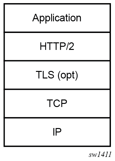
SBi communication uniformly uses an HTTP/2 stack as shown in HTTP/2 stack . Messages are sent over this HTTP/2 stack OpenAPI v3 [reference to https://spec.openapis.org/oas/v3.0.0]. Most of these messages use JSON encoding, but a few exceptions exist. For example, N1 NAS and N2 AP messages are signaled directly as binary format using the application/vnd.3gpp.5gnas and application/vnd.3gpp.ngap content types respectively.
Use the commands in the following context to change the common HTTP/2 and SBi behavior.
configure mobile-gateway profile http2Use the following command to configure a Python policy to apply Python scripts to any JSON-encoded messages. See Python support for more information.
configure mobile-gateway profile http2 python-policyThe MAG-c maintains multiple HTTP/2 connections to a peer, but does not use these equivalently. This is to ensure that if one connection fails, for example, because of stream ID exhaustion, a backup connection is available. When not enough connections are available, the MAG-c tries to periodically set up a new connection as determined by the following configuration, until enough connections are available.
configure mobile-gateway profile http2 connection-timerWhile a connection is established, the MAG-c periodically sends an HTTP/2 PING message as determined by the configuration of the ping-period command.
HTTP/2 messages are sent out with the configured IP dscp command value in the IP header, which defaults to 56.
When acting as an SBi client, the MAG-c creates a new stream for each SBi message sent, subject to the maximum number of outstanding streams. When HTTP/2 messages are unacknowledged, the MAG-c retransmits these messages periodically based on the following command.
configure mobile-gateway profile http2 fail-retry-intervalThe default interval is applied (default 5s) until a maximum number of attempts (default 0) has been reached based on the configuration of the following command.
configure mobile-gateway profile http2 fail-num-retriesconfigure mobile-gateway profile http2 request-timeoutAfter the request timeout, the message is canceled. The reason for the request timeout, in addition to the fail-retry-interval and the fail-num-retries command configurations, is that the latter only takes effect from the moment the message is sent on a stream. The configured request-timeout value is started from the moment the client service wants to send the message, including any time the message is queued if the maximum number of outstanding streams is reached.
configure mobile-gateway profile namf-profile transaction-timerFailure handling
The MAG-c supports flexible and consistent failure handling over multiple SBi applications such as UDM, AMF, PCF, and CHF. Use the following commands to configure failure handling for these applications:
- For timeout of SBi operations, use the fh-session-no-response command in the applicable context.
- To modify timeout actions for SBi operations use the retry-count and transaction-timer commands in the applicable context.
- For specific HTTP and application error codes, use the http-status-code command in the applicable context.
Use these commands to configure the following services in the contexts indicated:
- Namf_Communication
service
configure mobile-gateway profile amf-profile - get operation of the Nudm_SubscriberDataManagement
service
onfigure mobile-gateway profile udm-sdm-profile get-sm-subscription-data - subscribe operation of the Nudm_SubscriberDataManagement
service
configure mobile-gateway profile udm-sdm-profile create-subscription - registration operation of the Nudm_UEContextManagement
Service
configure mobile-gateway profile udm-uecm-profile register-smf - Npcf_SMPolicyControl
service
Specify per-operation values in the sbi-srvc-operation context of this profile.configure mobile-gateway profile pcf-profile
Applications support two or more of the following actions when there is a failure:
- terminate
Terminate the session.
- attempt-continue
Continue the triggering procedure and terminate the session if the failure cannot be handled. For example, a failure on Namf_Communication terminates the session when an update of F-TEID programming upon mobility fails. However, the session continues a failing QoS update by rejecting the triggering procedure.
- ap-continue
Take fallback actions to continue the session. In rare cases the session may still terminate, usually when the fallback action is not properly configured. The fallback option depends on the service or the operation:
- Npcf_SMPolicyControl
The SMPolicy association is removed and all communication with the PCF is stopped for the remainder of the session lifetime. The session can keep working with the latest PCF rules supplied or fall back to local rules only. Additionally, a failure handling limit can be configured with the fh-time-limit command, after which the session terminates anyway.
- Get operation of the Nudm_SubscriberDataManagement
The session setup continues with local configuration. A default QoS (5QI/ARP/session-AMBR) must be provisioned separately from the UDM, for example, using ADB or RADIUS.
- Subscribe operation of Nudm_SubscriberDataManagement
The session continues without UDM subscription.
- Registration operation of the Nudm_UEContextManagement service
The session continues without UECM registration.
- Nchf_ConvergedCharging
Charging is paused and removed from the FWA UP.
- Npcf_SMPolicyControl
The following alternative actions are also available. These behave the same as the main variants. However, after the initial failure the operation is first retried for a maximum of two alternative NF peers, if any are available:
- retry-and-terminate
- retry-and-attempt-continue
- retry-and-ap-continue
See NF peer discovery for more information about how to discover multiple NF Peers.
NRF failure handling
NRF services use a different mechanism for failure handling, because the NRF services are usually used system-wide instead of per session. Instead of per-operation failure handling, a failed NRF operation puts the NRF peer in a blocklist. Use the following command to configure the duration of the block for the applicable service:
- Nnrf_NFManagement
service
configure mobile-gateway pdn sba-client-services nrf-client nnrf-nfm blocklist-durationFor the Nnrf_NFManagement service the behavior is granularly configurable using the following commands:
- The heartbeat-nrf-blocklist command configures how often to retry and wait for a heartbeat NFUpdate operation before blocklisting.
- The nfm-nrf-blocklsit command configures how often to retry and wait for any other operation before blocklisting. This includes non-heartbeat NFUpdate operations, for example when updated SMF parameters have to be sent to the NRF.
The following specific status codes immediately block a peer, without retrying the Nnrf_NFManagement operation:
- For the NFRegister operation, any HTTP status code in the range 400 to 499, and HTTP status code 501 (Not Implemented)
- For the NFUpdate operation, including the heartbeat, HTTP status code 400 (Bad Request) and 501 (Not Implemented).
For the NFUpdate operation, including heartbeat, if an HTTP status code 404 (Not Found) is received, the MAG-c locally removes the registration and trigger a new NFRegister operation toward the same NRF peer.
If the MAG-c is registered with an NRF peer that is blocklisted, the MAG-c triggers a new NFRegister operation to the next peer, taking into account any configured NF Instance or IP priority.
- Nnrf_NFDiscovery
service
configure mobile-gateway pdn sba-client-services nrf-client nnrf-disc blocklist-durationFor the Nnrf_NFDiscovery service, the peer is blocklisted immediately if a single operation is rejected or times out and the discovery procedures use other configured NRF peers.
When an HTTP 429 (Too Many Requests) status code is received, the blocklist duration is set to the value of the retry-after command header.
PCF-based policy management
In a 5G core network, the Policy Control Function (PCF) is used to retrieve policy operations related to traffic forwarding, QoS, and charging. This is a pure policy management function and does not include any authentication functionality, in contrast for example to RADIUS, where authentication and policy management (authorization) are often combined.
To enable PCF communication, do the following:
-
Use the following command to configure a PCF SMPolicyControl client service.
configure mobile-gateway pdn sba-client-services pcf-client npcf-smpolicycontrol - Use the following command to configure an interface for the MAG-c to use to communicate with the PCF.
configure mobile-gateway pdn sba-client-services pcf-client npcf-smpolicycontrol interface - Provide the following optional configuration:
- An FQDN to identify the service by other NF peers. For example, when generating callback functions, the MAG-c can use the FQDN in the URI, instead of the IP address; see URI construction for more information about how URIs are constructed.
- An NF ID list to specify NF instances that can be used for the PCF function; see Local NF ID list-based discovery for more information. This command is required if the PCF is not dynamically discovered using NRF.
- An HTTP2 profile to influence generic HTTP/2 and SBI parameters; see HTTP/2 , OpenAPI, and Python for more information.
- A PCF profile that contains parameters to handle PCF failure handling as
configured using the following command. See Failure handling for more
information.
This also allows configuration of feature support signaling to the PCF using the supported-features commands.configure mobile-gateway profile npcf
- Use the following command to enable the client
service.
configure mobile-gateway pdn sba-service-realm client-service
When a PCF client service is configured, FWA sessions automatically attempt to contact the PCF. Use the following command to configure a dynamic policy in the ADB and bypass PCF for specific sessions.
configure mobile-gateway profile authentication-database entry dynamic-policyYou can also configure per DNN parameters using commands in the following context:
configure mobile-gateway pdn apn pcf-selection Options to configure include:
- the nf-id-list and the npcf-profile commands override their equivalents in the client service instance
- the dnn-format command modifies how the DNN is sent to the PCF
- the exclude commands exclude sending specific IEs to the PCF.
PCF interaction is always performed after the authentication flow procedure, including any RADIUS authentication, is completed. The PCF can provide multiple policy decisions, such as an SLA profile, subscriber profile, subscriber filters, and QoS overrides. If any of these values are also provided during the authentication flow, the PCF value overrides these.
Nokia supports vendor-specific attributes in the SMPolicyDecision context, using the vendorSpecific-6527 container. The following attributes are supported:
- subscriberProfile—string indicating the subscriber profile
- slaProfile—string indicating the SLA profile
- sapTemplate—string indicating the SAP template
- groupInterfaceTemplate—string indicating the group interface template
- intermediateDestinationID—string indicating an intermediate destination ID, typically used to apply VPORT QoS
- QoSOverride—string representing specific QoS overrides, using the same format as the RADIUS Alc-Subscriber-QoS-Override attribute which can be present up to 18 times
- A subscriber Filter—container that can contain the following sub-objects:
- ingressIpv4—string representing an IPv4 filter that will be applied on ingress
- egressIpv4—string representing an IPv4 filter that will be applied on egress
- ingressIpv6—string representing an IPv6 filter that will be applied on ingress
- egressIpv6—string representing an IPv6 filter that will be applied on egress
The MAG-c can retrieve an updated policy from the PCF using the Npcf_SMPolicyControl Update service call. The SMF only does this upon triggers that are set by the PCF when providing a policy decision. The following trigger codes are supported:
- RES_MO_RE— A PDU Session Modification Request has been received from the UE to add or remove a PCC rule.
- UE_IP_CH—any time an IP address is allocated or freed using DHCP/DHCPv6
- DEF_QOS_CH—if default QoS parameters are changed via another interface, for example, because of a UDM subscription update
- SE_AMBR_CH—if the Session AMBR is changed via another interface, for example, because of a UDM subscription update.
- SAREA_CH— if a location change was detected that changes the Serving Area.
- SCNN_CH—if a location change was detected that changes the Serving CN Node.
- RE_TIMEOUT—the PCF provides a revalidation timer after which this update is triggered
- REF_QOS_IND_CH—if support for reflective QoS is changed in a PDU Modification Request message
- SCELL_CH—if a location change was detected that changed the Serving Cell.
Alternatively, the PCF can directly update the policy on the MAG-c using the SmPolicyUpdateNotification callback service call. This call is executed against an explicit URI provided by the MAG-c during setup, which contains all required session context.
The NPCF_SMPolicyControl service creates a policy association for a session that can be updated or removed at any time. Each policy association has its own identifier assigned by the PCF, which may be different from MAG-c session-specific identifiers such as SUPI. The MAG-c supports the following operations of the NPCF_SMPolicyControl service, as shown in PCF Policy Control Operations:
-
The Create operation is used to create the policy control association. In the request, the MAG-c will send various metadata such as SUPI, GPSI, PEI, DNN, S-NSSAI, and subscribed QoS. The MAG-c also includes a notification callback URI for the UpdateNotify operation. The PCF responds to this request with an association ID identifying the policy association, and the initial policy data.
The create operation is part of the initial session setup; see FWA session setup for 5G for more information.
- The Update operation that is used to inform the PCF that one or more signaled triggers have been activated. The MAG-c signals the policy association ID, applicable update trigger, and any metadata to the PCF. The PCF responds to the update with the changed policy data, if any.
-
The UpdateNotify operation is used by the PCF when it requires to update a policy decision immediately. In this case it sends the request to the URI provided during the creation of the policy association, including the changed policy data. The MAG-c applies the changed policy and sends a response.
Note: This operation does not use the association ID; the MAG-c provides any local identifier it requires as part of the callback URI. - The Delete operation is used by the MAG-c to stop policy enforcement and remove the policy association. This operation is executed during FWA session deletion.