Multi-Access Gateway Lawful Intercept - Fixed Wireless Access with Geo-redundancy
This chapter provides information about MAG-c LI - FWA with geo-redundancy.
Topics in this chapter include:
Applicability
The information and the configuration in this chapter are based on Multi-Access Gateway (MAG) controller (MAG-c) and SR OS Release 24.3.R1.
Overview
This chapter provides Lawful Intercept (LI) configurations for geo-redundant Fixed Wireless Access (FWA) MAG setup. For the FWA LI basics, see the Multi-Access Gateway Lawful Intercept - Fixed Wireless Access chapter.
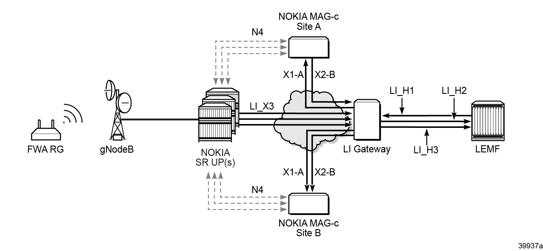
This chapter provides a configuration example for the 3GPP X1, X2, and X3 interfaces. Interfaces for the MAG shows the X interfaces which are based on 3GPP TS 33.107 and TS 33.108 for 4G and on 3GPP TS 33.127 and RS 33.128 for 5G.

The X interfaces for the MAG are the following:
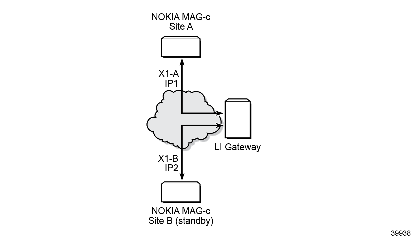
- The X1 interface in this document refers to the 4G X1_1 and the 5G LI_X1 interface. The X1-A interface connects from MAG-c site A (MAG-c A) to the LI Gateway (LIG) and the X1-B interface connects from MAG-c site B (MAG-c B) to the LIG. It is assumed that the X1 traverses through an IP routing network in between the MAG-c and the LIG. The X1 interface is used for configuration: setting up LI targets and the MAG-c LI infrastructure.
- The X2 interface in this document refers to the 4G X2_1 and the 5G LI_X2. It is also known as the Intercept Relation Information (IRI) interface. The X2-A interface connects from MAG-c site A (MAG-c A) to the LI Gateway (LIG) and the X2-B interface connects from MAG-c site B (MAG-c B) to the LIG. It is assumed that the X2 traverses through an IP routing network in between the MAG-c and the LIG. The X2 interface is used for transporting IRI LI target related events to the LIG. In 4G, the X2 interface to the LIG is often referred to as delivery function (DF) 2 peer (DF2 peer).
- The X3 interface in this example refers to the Communication Content (CC) interface for both 4G and 5G. The CC interface is used to transport the mirrored packets from each User Plane (UP) to the LIG. In 4G, the LIG often is often referred to as the DF3 peer.
Configuration
This section is separated into two parts:
LI geo-redundant infrastructure setup
The infrastructure for LI is typically set up during commissioning. This section is separated into two parts: one for 4G and the other for 5G.
4G LI geo-redundant infrastructure setup for X1 interface
The 4G X1 interface on the MAG-c is a CLI interface over SSH. For geo-redundancy, it is expected that MAG-c site A and MAG-c site B have two different SSH IP addresses. The SSH address can be the local SSH address used for main management login. The 4G LI X1 interfaces on both MAG-c systems are always active, as shown in 4G X1 interfaces in geo-redundant MAG-c systems (solid lines between MAG-c systems and LIG).

4G LI geo-redundant infrastructure setup for X2 interface
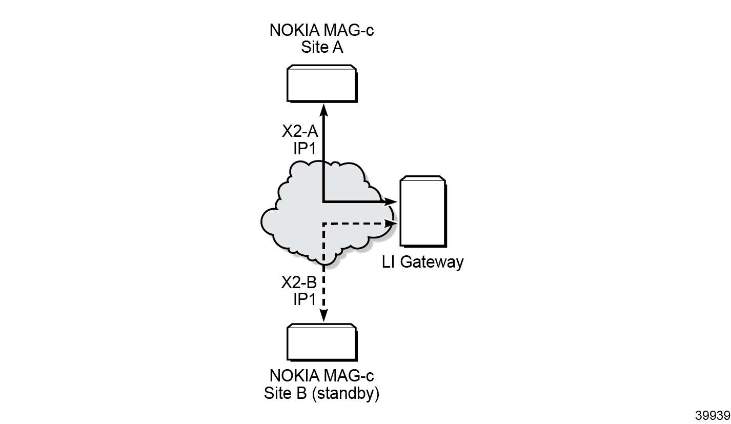
The 4G X2 interface on the MAG-c is a TCP interface where TLS is optional. The LIG X2 interface known DF2-peer is required to be configured via SSH. For geo-redundancy, both MAG-c site A and MAG-c site B must share the same local IP address. Only one X2 interface is active. Both MAG-c IP1 interfaces are tracking the mc-mobile active/standby state. The IP1 interfaces on both MAG-c systems are also utilizing a routing protocol for advertisement. Therefore, only the active MAG-c announces the IP1 to the LIG via the routing protocol. 4G X2 interfaces in geo-redundant MAG-c systems shows that both X2 interfaces have IP address IP1, but only the X2 interface on MAG-c site A is active (solid line) while the X2 interface on MAG-c site B is standby (dashed line).

Step 1: Configure the IP1 interface identically on MAG-c-A and MAG-c-B and ensure the interface tracks the mc-mobile state. The CLI output only shows a MAG-c-A, but the configuration on MAG-c-B is identical.
*A:MAG-c-A>config>router#
            interface "Loopback interface for LI X2" create
                description "Loopback interface for LI X2"
                address 30.0.0.6/32
                loopback
                track-mobile
            exit
Step 2: Attach the routing interface to a routing protocol of your choice or within a routing policy for route export.
Step 3: Configure the LI X2 address.
*A:MAG-c-A>config>li# info
----------------------------------------------
        mobile-gateway
            local-interface 30.0.0.7 router vprn4 override-x2-interface 30.0.0.6 x2-router vprn4
The local interface configured, in this example 30.0.0.7, must be the same on both MAG-c systems.
For 4G, the LI X2 interface utilizes the local-interface IP address but the override X2 address will override the local-interface IP address. Therefore, the override command for 4G X2 looks redundant. The override command is targeted for 5G LI X2. With this, the 5G X1 interface will utilize the local interface while the 5G X2 interface will utilize the override IP address.
5G LI geo-redundant infrastructure setup for X1 interface
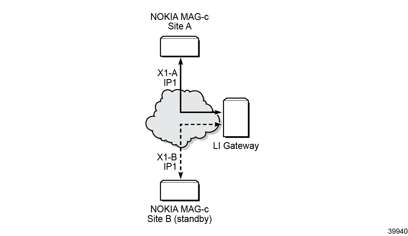
The 5G X1 interface on the MAG-c is a TCP/TLS interface. For geo-redundancy, both MAG-c site A and MAG-c site B must share the same IP address. Only one X1 interface will be active. Both MAG-c IP1 interfaces are tracking the mc-mobile active/standby state. The IP1 interface on both MAG-c systems are also utilizing a routing protocol for advertisement. Therefore, only the active MAG-c announces the IP1 to the LIG via the routing protocol, as shown in 5G X1 interfaces in geo-redundant MAG-c systems.

Step 1: Configure the IP1 interface on MAG-c-A and MAG-c-B and ensure that the interface tracks the mc-mobile state.
*A:MAG-c-A>config>router#
            interface "Loopback interface for 5G LI X1" create
                description "Loopback interface for 5G LI X1"
                address 30.0.0.5/32
                loopback
                track-mobile
            exit
Step 2: Attach the routing interface to a routing protocol of your choice or within a routing policy for route export.
Step 3: Configure the local LI X1 address on MAG-c-A and MAG-c-B.
*A:MAG-c-A>config>li# info
----------------------------------------------
        mobile-gateway
            li-x1
                li-x1-local-interface 30.0.0.5 router Base local-port 443
5G LI geo-redundant infrastructure setup for X2 interface
The 5G X2 interface on the MAG-c is a TCP/TLS interface and it follows the same configuration as 4G X2 interface.

In a similar way as for 4G X2, only the active MAG-c announces IP1 to the LIG. If the X2 interface is already configured for 4G, no additional configuration is required for 5G. Both 4G X2 and 5G X2 utilize the same interface and source IP address to communicate with the LIG.
The configuration is exactly the same as 4G X2 and the routing interface will be associated to a routing protocol or a routing policy for route export. Only the configuration on MAG-c-A is shown; the configuration on MAG-c-B is identical.
*A:MAG-c-A>config>router# info
----------------------------------------------
            interface "Loopback interface for LI X2" create
                description "Loopback interface for LI X2"
                address 30.0.0.6/32
                loopback
                track-mobile
            exit


*A:MAG-c-A>config>li# info
----------------------------------------------
        mobile-gateway
            local-interface 30.0.0.7 router vprn4 override-x2-interface 30.0.0.6 x2-router vprn4
LI geo-redundant infrastructure setup for N4
The SR requires the secret key to be provisioned to decrypt the PFCP LI IEs. Therefore, both MAG-c-A and MAG-c-B share the same PFCP LI shared key.
A:MAG-c-A>config>li# info
        sci
            pfcp-li-shared-key "Secretkey”
        exit
User plane configuration
In this application, the UP is non-redundant and is managed by the geo-redundant CP. The configuration is as described in the 7450 ESS, 7750 SR, 7950 XRS, and VSR System Management Guide.
A:sros1>config>mirror# info
----------------------------------------------
        mirror-dest 1 name "1" create
            encap
                layer-3-encap ip-udp-shim create
                    direction-bit
                    router Base
                    gateway create
                        ip src 1.1.1.1 dest 1.1.1.2
                        udp src 65111 dest 65111
                    exit
                exit
                no shutdown
In the LI context, this mirror destination requires reference.
A:sros1>config>li# info
        li-source 1
        no shutdown
4G and 5G LI target provisioning on a geo-redundant setup
FWA LI target provisioning typically consists of three steps.
The reason for provisioning the target as both a 4G and 5G target is because the service provider might not know if the FWA RG is 4G or 5G capable. However, in the case where the service provider can predetermine the client type, then it is possible to only perform step 1 and 3 if the RG is only 4G capable and only step 2 and 3 if the RG is 5G capable with the ability to fall back to 4G.
It is highly recommended that provisioning of LI targets via SSH takes place on the standby MAG-c first before the active MAG-c. This is applicable to creation, modification, and deletion of LI targets.
Provisioning of 4G IRI targets
The provisioning of 4G IRI is identical on both MAG-c site A and MAG-c site B:
A:MAG-c-A>config>li# info
----------------------------------------------
        mobile-gateway
            local-interface 10.195.160.181 router vprn100 override-x2-interface 10.195.160.182 x2-router vprn100
            custom-correlation-id-format disable
            server-tls-profile  "li-server-tls-profile"
            client-tls-profile  "li-client-tls-profile"
            3gpp-5g-release rel-base
            li-x1
                li-x1-local-interface 10.195.160.181 router 100 local-port 50001
            exit
            df-peer 2 df2-addr 10.178.229.137 df2-port 10047 df2-tls-profile li-client-tls-profile
            target imsi id 310310995002222 intercept iri peer 2 liid 17097478
            target imsi id 310310995003362 intercept iri peer 2 liid 310310995003362
        exit
        pfcp-li-shared-key "YHTJfusmNsAtfdCMSBvb2qQMUwzSiefunPs=" hash2
Provisioning of 5G IRI targets
To provision 5G IRI, the ETSI 103.221-1 protocol is used. The steps include:
- CreateDestination to create the destination for IRI message, which is called the destination ID (DID).
- ActivateTask to create the LI target and specify the DID for the IRI message.
Provisioning of 4G and 5G CC targets
The provisioning of CC for both 4G and 5G is identical on both MAG-c site A and MAG-c site B:
A:MAG-c-A>config>li# info
----------------------------------------------
        mobile-gateway
            local-interface 10.195.160.181 router vprn100 override-x2-interface 10.195.160.182 x2-router vprn100
            operator-id TMBL
            tls
            custom-correlation-id-format disable
            server-tls-profile  "li-server-tls-profile"
            client-tls-profile  "li-client-tls-profile"
            3gpp-5g-release rel-base
            nf-id-value uuid
            li-x1
                li-x1-local-interface 10.195.160.181 router 100 local-port 50001
                admf-peer 1 admf-addr 10.178.229.136 x1-port 10443
            exit
            df-peer 2 df2-addr 10.178.229.137 df2-port 10047 df2-tls-profile li-client-tls-profile
            target imsi id 310310995002222 intercept iri peer 2 liid 17097478
            target imsi id 310310995003362 intercept iri peer 2 liid 310310995003362
        exit
        pfcp-li-shared-key "YHTJfusmNsAtfdCMSBvb2qQMUwzSiefunPs=" hash2
        target "310310995003362"
            source 1 imsi 310310995003362 egress ingress intercept-id 17097489 mirror-destination "1"
        target "310310995003444"
            source 1 imsi 310310995003444 egress ingress intercept-id 17097487 mirror-destination "1"
        exit
For all bootup scenarios on a geo-redundant setup where the LI configuration is locally saved, the active MAG-c node will load the LI configuration and apply the configuration to both active and standby MAG-c.
Conclusion
This chapter provides a configuration example for FWA LI for a pair of geo-redundant MAG-c. The infrastructure for LI is typically set up once during commissioning. Afterward, depending on whether the UE is a 4G UE or a 5G UE, the LIG may be required to provision the LI target on both active and standby MAG-c.