BTV multicast configuration examples
Overview
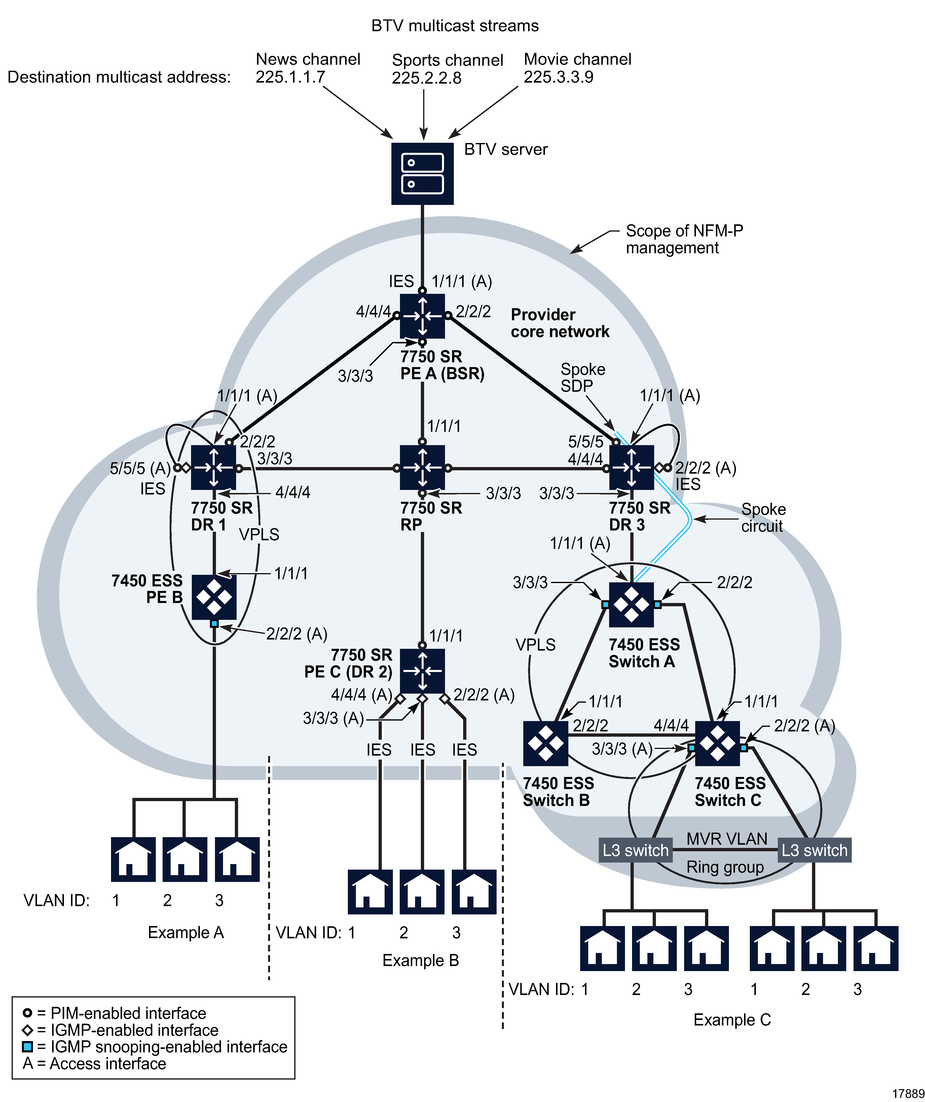
Figure 70-17, BTV multicast delivery examples shows a simple BTV network and three methods of content delivery, examples A, B, and C. The sequence of specific configuration steps for each example follows general device, network and multicast configuration information common to all examples.
Note: In the examples on the following pages, references to “IGMP-snooping” may generally be read as “IGMP- or MLD-snooping”, provided the routers employed in the configurations support the MLD protocol.
Device preconfiguration
A network device requires CLI preconfiguration before it can be managed by the NFM-P.
The primary CLI preconfiguration actions for a device are:
See Chapter 8, Device commissioning and management and the specific device documentation for more information about enabling device functionality before using the NFM-P.
Figure 70-17: BTV multicast delivery examples

After CLI preconfiguration, further actions are required:
See Chapter 9, Device discovery for more information about device discovery and management using NFM-P.
Network preconfiguration
The core network shown in Figure 70-17, BTV multicast delivery examples represents a fully meshed group of devices. For simplicity, only the devices relevant to the BTV multicast examples are shown.
Network preconfiguration consists of the following sequence of actions:
1 |
Configure network devices for in-band or out-of-band management. See Chapter 8, Device commissioning and management for more information. |
2 |
Configure a system interface on each device to serve as the identifier for the device. See Chapter 27, NE routing and forwarding for more information. |
3 |
Configure network interfaces on each router to establish a full mesh of interconnectivity between devices. In Figure 70-17, BTV multicast delivery examples the interfaces to be configured are PE A, ports 1/1/1, 2/2/2, 3/3/3, and 4/4/4; DR 1, port 2/2/2; RP, ports 1/1/1, 2/2/2, and 4/4/4; and DR 3, ports 1/1/1 and 4/4/4. See Chapter 27, NE routing and forwarding for more information. |
4 |
Cable the network-interface ports between routers in the core network to establish the physical connectivity shown in Figure 70-17, BTV multicast delivery examples . |
5 |
Use CLI ping commands to check IP connectivity between devices. See the device documentation for more information. |
6 |
Enable IGPs such as RIP, OSPF, or IS-IS on devices according to network size and complexity. See Chapter 28, Routing protocol configuration for information about enabling routing protocols. |
7 |
Enable an inter-AS routing protocol such as BGP or OSPF to PE routers, if required. See Chapter 28, Routing protocol configuration for more information. |
8 |
Create routing policies as required. Create one multicast group for each BTV multicast destination address during policy creation. See Chapter 27, NE routing and forwarding for more information. |
9 |
Configure routing protocols and apply routing policies as required. See Chapter 28, Routing protocol configuration for more information. |
10 | Configure LDP and MPLS, if required. See Chapter 28, Routing protocol configuration for information about configuring LDP. See Chapter 31, MPLS for information about configuring MPLS. |
Multicast configuration common to all examples
The network connections shown between PE A and DR 1 and between PE A and DR 3 represent redundant multicast routes used by PIM in the event of an RP failure. PIM dynamically adjusts to BSR or RP failure by electing a replacement BSR or RP or by using a previously defined backup BSR or RP. PIM chooses the most appropriate source for a multicast stream based on path cost and source availability and bypasses the RP if a better source for a multicast stream is found. For simplicity, Figure 70-17, BTV multicast delivery examples does not show routes to PE C (DR 2) from DR 1 or DR 3. As shown, PE C (DR 2) is isolated from multicast traffic in the event of RP failure.
Network multicast configuration common to all three examples involves the following sequence of actions:
1 |
Enable IGMP on routers DR 1, PE C (DR 2), and DR 3. See To enable IGMP on a routing instance for more information. |
2 |
Configure IGMP on routers DR 1, PE C (DR 2), and DR 3. See To configure an IGMP site on a router for more information. |
3 |
Enable PIM on routers PE A, RP, DR 1, PE C (DR 2), and DR 3. See To enable PIM on a routing instance for more information. |
4 | Configure PIM on routers PE A, RP, DR 1, PE C (DR 2), and DR 3. See To configure PIM on a routing instance for more information.
|
5 |
Create PIM interfaces at PE A, ports 1/1/1, 2/2/2, 3/3/3, and 4/4/4; RP, ports 1/1/1, 2/2/2, 3/3/3 and 4/4/4; DR 1, ports 2/2/2 and 3/3/3; DR 2, port 1/1/1 and DR 3, ports 4/4/4 and 5/5/5. See To create a PIM interface on a base routing instance or VPRN routing instance for more information. |
6 |
Create QoS, scheduling, and accounting policies for the ingress BTV traffic. See Chapter 49, Policies overview for more information. |
7 |
Create an IES from PE A, port 1/1/1, to the BTV multicast provider's network. See To create an IES and To configure an IES site for more information. Enable PIM on the IES SAP during IES creation. |
Example A configuration
In Example A, IGMP join requests from residential hosts ingress a VPLS SDP. IGMP snooping on the VPLS registers the join requests on the local switch. The switch sends the requests over the VPLS, which is physically cross-connected to an IGMP- and PIM-enabled IES SAP on the DR. PIM on the DR requests the desired multicast stream, if not present, from the RP. The requested stream then traverses the VPLS and is sent to end users.
1 |
Configure PE B, port 1/1/1 and DR 1, port 4/4/4 as network ports. See To configure Ethernet ports for more information. |
2 |
Configure PE B, port 2/2/2 and DR 1, port 1/1/1 as access ports. See To configure Ethernet ports for more information. |
3 |
Cable DR 1, port 3/3/3, and PE B, port 1/1/1 to establish physical connectivity. |
4 |
Configure DR 1, port 5/5/5 as an access port. See To configure Ethernet ports for more information. |
5 | Create an IES on DR 1, port 5/5/5. See To create an IES and To configure an IES site for more information. |
6 |
Connect a cable between ports 1/1/1 and 5/5/5 on DR 1 as a service cross connect. |
7 |
Create QoS, scheduling, filter, and accounting policies to apply to egress BTV traffic during service creation. See Chapter 49, Policies overview for information about policy creation. |
8 | Create a distributed VPLS with endpoints at PE B, port 2/2/2 and DR 1, port 1/1/1. See To create a VPLS and To configure a VPLS site for more information. |
Example B configuration
In Example B, an IGMP join request ingresses an IES SAP on the DR. PIM on the DR requests the desired multicast stream, if not present, from the RP. The requested stream is then delivered over an IES to an end user.
1 |
Configure PE C (DR 2), ports 2/2/2, 3/3/3, and 4/4/4 as access ports. See To configure Ethernet ports for more information. |
2 |
Create QoS, scheduling, filter, and accounting policies to apply to egress BTV traffic during IES creation. See Chapter 49, Policies overview for information about policy creation. |
3 | Create IES services on PE C (DR 2), ports 2/2/2, 3/3/3, and 4/4/4 that terminate on the CE set-top devices. See To create an IES for more information. |
Example C configuration
In Example C, IGMP join requests from residential hosts pass over an MVR VLAN to an VPLS. IGMP snooping on the VPLS registers the join requests on the local switch, which passes them over the VPLS to a spoke SDP on the DR. The spoke SDP' port is physically cross-connected to an IGMP- and PIM-enabled IES SAP on the DR. PIM on the DR requests the desired multicast stream, if not present, from the RP, then sends the stream over the VPLS and MVR VLAN to the end users.
1 |
Create a BTV MVR VLAN of L3 switches in a ring group with endpoints on Switch A, ports 2/2/2 and 3/3/3. See Sample BTV VLAN configuration and To create an OmniSwitch BTV VLAN service for more information. For redundancy, the MVR VLAN can be configured with endpoints on different switches. A VLL between the two switches acts as an unbreakable connection. |
2 |
Enable and configure IGMP snooping on the bridge instances for the L3 switches included in the MVR VLAN. |
3 |
Create QoS, scheduling, filter, and accounting policies to apply to egress BTV traffic during service creation. See Chapter 49, Policies overview for information about policy creation. |
4 | Configure the following as network ports:
|
5 | Create a distributed VPLS consisting of Switch A, Switch B, and Switch C. See To create a VPLS and To configure a VPLS site for more information.
|
6 |
Configure DR 3, port 2/2/2 as an access port. See To configure Ethernet ports for more information. |
7 | Create an IES on DR 3, port 2/2/2. See To create an IES and To configure an IES site for more information. |
8 |
Connect a cable between ports 1/1/1 and 2/2/2 on DR 3 as a service cross connect. |
9 |
Create a VPLS spoke SDP at DR 3, port 1/1/1. See To create an HVPLS for more information. |
Example D configuration
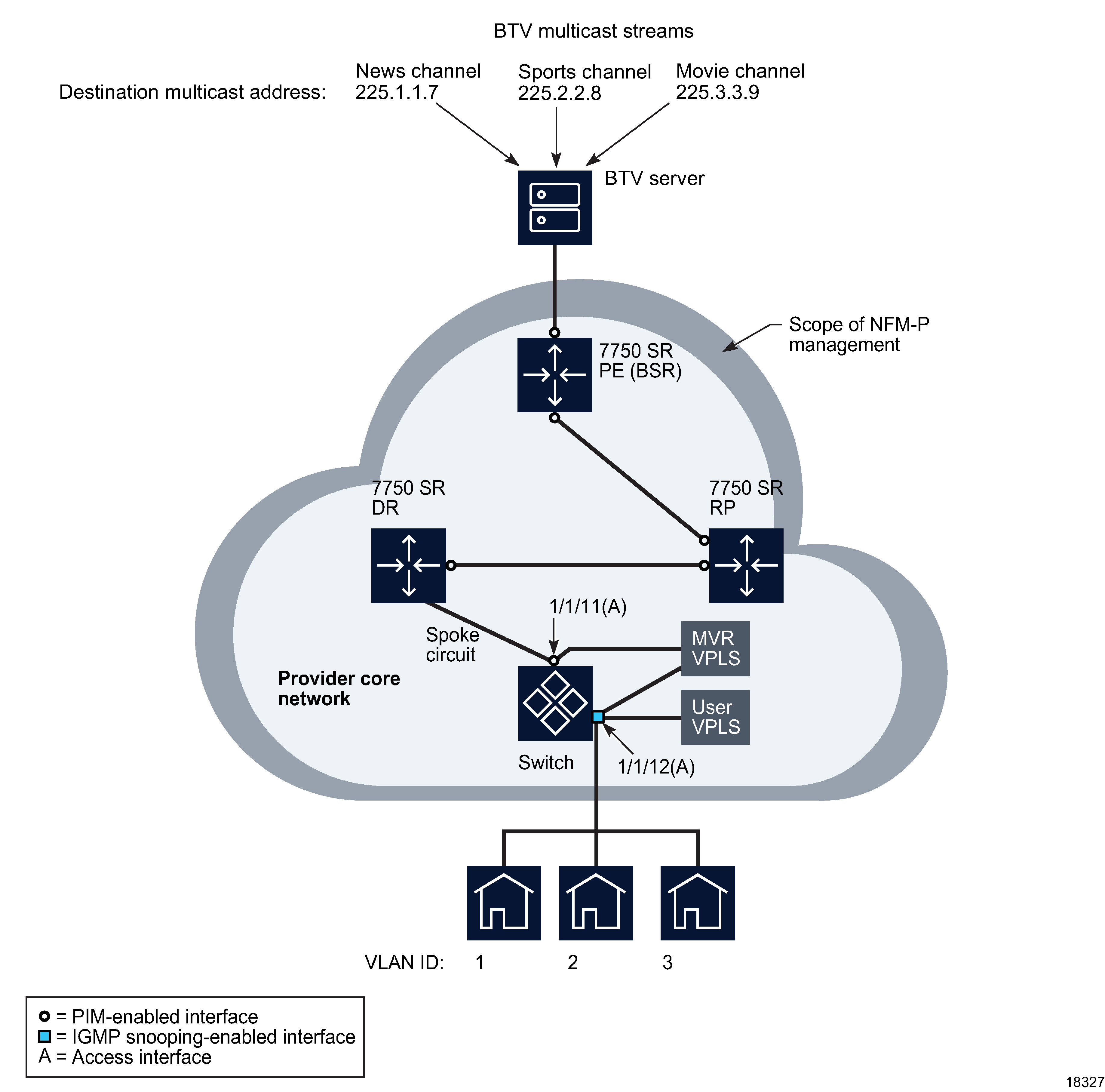
Figure 70-18, BTV multicast delivery using MVR on VPLS example shows an example of BTV multicast delivery using MVR on VPLS. See Figure 70-17, BTV multicast delivery examples , and Network preconfiguration and Multicast configuration common to all examples for common network configuration information.
Figure 70-18: BTV multicast delivery using MVR on VPLS example

BTV multicast delivery using MVR on VPLS
In Example D, IGMP join requests from residential hosts are sent to a user VPLS on the 7450 ESS. IGMP snooping on the user VPLS registers the join requests on the switch, which sends them to the 7750 SR DR. PIM on the DR requests the desired multicast stream, if not present, from the RP, then sends the stream over the MVR VPLS to the user VPLS, from which the multicast stream is sent to the end users.
1 |
Create a multicast package policy to apply to the 7450 ESS that belongs to the MVR VPLS. See Chapter 52, Multicast policies for more information. |
2 | Configure the following ports as access ports. See To configure Ethernet ports for more information. |
3 |
Create an MVR VPLS on the 7450 ESS with SAPs 1/1/11 and 1/1/12. Apply the previously defined multicast package policy to the MVR VPLS. |
4 | Create a user VPLS on SAP 1/1/12 of the 7450 ESS.
|
5 |
Create a spoke circuit between the 7450 ESS (endpoint 1/1/11) and the 7750 SR DR. |