Ethernet connectivity fault management (ETH-CFM)
The IEEE and the ITU-T have cooperated to define the protocols, procedures, and managed objects to support service-based fault management. Both the IEEE 802.1ag standard and the ITU-T Y.1731 recommendation support a common set of tools that allow users to deploy the necessary administrative constructs, management entities and functionality, and Ethernet Connectivity Fault Management (ETH-CFM). The ITU-T has also implemented a set of advanced ETH-CFM and performance management functions and features that build on the proactive and on-demand troubleshooting tools.
CFM uses Ethernet frames and is distinguishable by Ethertype 0x8902. In specific cases, the different functions use a reserved multicast Layer 2 MAC address that could also be used to identify specific functions at the MAC layer. The multicast MAC addressing is not used for every function or in every case. The Operational Code (OpCode) in the common CFM header is used to identify the PDU type carried in the CFM packet. CFM frames are only processed by IEEE MAC bridges.
IEEE 802.1ag and ITU-T Y.1731 functions that are implemented are available on the platforms
This section provides configuration examples for each of the functions. It also provides the various OAM command line options and show commands to operate the network. See the 7705 SAR Gen 2 MD-CLI Command Reference Guide and 7705 SAR Gen 2 Classic CLI Command Reference Guide for a detailed description of the CLI commands to build the necessary constructs and management points.
The following table lists and expands the acronyms used in this section.
| Acronym | Expansion | Supported platform |
|---|---|---|
|
1DM |
One-way Delay Measurement (Y.1731) |
All |
|
AIS |
Alarm Indication Signal |
All |
|
CCM |
Continuity Check Message |
All |
|
CFM |
Connectivity Fault Management |
All |
|
CSF |
Client Signal Fail (Receive) |
All |
|
DMM |
Delay Measurement Message (Y.1731) |
All |
|
DMR |
Delay Measurement Reply (Y.1731) |
All |
|
ED |
Ethernet Defect (Y.1731 sub OpCode of MCC) |
All |
|
LBM |
Loopback message |
All |
|
LBR |
Loopback reply |
All |
|
LMM |
(Frame) Loss Measurement message |
Platform specific |
|
LMR |
(Frame) Loss Measurement response |
Platform specific |
|
LTM |
Linktrace message |
All |
|
LTR |
Linktrace reply |
All |
|
MCC |
Maintenance Communication Channel (Y.1731) |
All |
|
ME |
Maintenance Entity |
All |
|
MA |
Maintenance Association |
All |
|
MD |
Maintenance Domain |
All |
|
MEP |
Maintenance Association Endpoint |
All |
|
MEP-ID |
Maintenance Association Endpoint Identifier |
All |
|
MHF |
MIP Half Function |
All |
|
MIP |
Maintenance Domain Intermediate Point |
All |
|
OpCode |
Operational Code |
All |
|
RDI |
Remote Defect Indication |
All |
|
TST |
Ethernet Test (Y.1731) |
All |
|
SLM |
Synthetic Loss Message |
All |
|
SLR |
Synthetic Loss Reply (Y.1731) |
All |
|
VSM |
Vendor Specific Message (Y.1731) |
All |
|
VSR |
Vendor Specific Reply (Y.1731) |
All |
Facility MEPs
Facility MEPs improve scalability, reduce operational overhead, and provide fate sharing without requiring service MEPs. This enables fault notification for Epipe services that share a common transport. Facility MEPs recognize failure based solely on ETH-CFM detection mechanisms.
The following facility MEPs exist, as described below:
- port (physical) – detects port failure where LOS may be hidden by some intervening network
- router IP interface (logical) – validates the Layer 2 connectivity between IP endpoints (troubleshooting only, no CCM functions)
In general, a facility MEP detects failure conditions using ETH-CFM at the Ethernet Transport Layer. The detection is based solely on the MEP entering a fault state as a result of ETH-CC. Conditions outside the scope of ETH-CFM have indirect influence on the state of the MEP. For example, after the failure of a port, CCM messages cannot reach the destination. This condition causes the MEP to enter a fault state after the 3.5 × interval expires, with the only exception being the acceptance of AIS on a Tunnel MEP. AIS received on all other facility MEPs is discarded silently when normal level matching targets the local facility MEP.
Facility MEPs are supported as part of a down MEP only. Facility MEPs validate the point-to-point Ethernet transport between two endpoints, which does not include validating switching functions outside this Ethernet transport. The service MEPs validate these additonal switching functions outside the point-to-point Ethernet transport.
A facility MEP allows for the scaling improvements using fate sharing and leveraging OAM mapping. The OAM mapping functions are part of the fault propagation functions and allow ETH-CFM to move from alarms only to network actions. Service-based MEPs are not required to generate AIS in reaction to a facility MEP fault. OAM mapping and generation of fault via fault-propagation means or the AIS function are only available for Epipe services. There is no equivalent AIS generation as part of the facility fault for VPLS. Service MEPs do not require the SAP transition in the VPLS service context. Normal SAP transition functions do not occur when these services are configured to accept the tunnel fault, or in reaction to a facility fault, where the underlying port or LAG transitions the SAP.
Facility MEPs are created in the same manner as service MEPs, both related to the ETH-CFM domain and association. However, the association used to build the facility MEP does not include a bridge identifier. The CLI ensures that a bridge ID is not configured when the association is applied to a facility MEP.
Service MEPs and facility MEPs may communicate with each other, as long as all the matching criteria are met. Because facility MEPs use the standard ETH-CFM packets, there is nothing contained in the packet that would identify an ETH-CFM packet as a facility MEP or service MEP.
Facility MEPs are not supported on ports that are configured with Ethernet Tunnels (G.8031) and only facility MEPs of 1 second and above are supported on the ports that are involved in an Ethernet Ring (G.8032).
Common actionable failures
AIS operates independently from the low-priority-defect command option. The low-priority-defect command option affects only the ETH-CFM fault propagation and alarming outside the scope of AIS. By default, a fault in the CCM MEP state machine generates AIS when it is configured. Defect conditions and priority settings summarizes the ETH-CC defect condition groups, configured low-priority-defect setting, priority, and defect as it applies to fault propagation. AIS maintains its own low-priority-defect command option, which can be used to exclude the CCM defect RDI from triggering the generation of AIS.
| Defect | Low priority defect | Description | Causes | Priority |
|---|---|---|---|---|
|
DefNone |
n/a |
No faults in the association |
Normal operations |
n/a |
|
DefRDICCM |
allDef |
Remote Defect Indication |
Feedback mechanism to inform unidirectional faults exist. It provides the feedback loop to the node with the unidirectional failure conditions. |
1 |
|
DefMACStatus (default) |
macRemErrXcon |
MAC Layer |
Remote MEP is indicating a remote port or interface not operational. |
2 |
|
DefRemoteCCM |
remErrXon |
No communication from remote peer |
MEP is not receiving CCM from a configured peer. The timeout of CCM occurs at 3.5 x the local CC interval. As per the specification, this value is not configurable. |
3 |
|
DefErrorCCM |
errXcon |
Remote and local configurations do not match the required configuration |
Caused by different interval timer, domain-level issues (lower value arriving at a MEP configured with a higher value), MEP receiving CCM with its MEP-ID. |
4 |
|
DefXconn |
Xcon |
Cross Connected Service |
The service is receiving CCM packets from a different association. This could indicate that two services have merged or there is a configuration error on one of the SAP or bindings of the service, incorrect association identification. |
5 |
A facility MEP may trigger two distinct actions as a result of fault. If they have been configured to do so, Epipe services generate AIS as a result of a failure. The level of the AIS is derived from the facility MEP. Multiple client-meg-level configurations can be configured under the facility MEP to allow for operational efficiency in the event a change is required. However, only the lowest AIS level is generated for all the linked and applicable services. VPLS SAPs transition the SAP state if they are configured to react to the facility MEP state. In addition, Epipe services may also take advantage of OAM and mapping functions.
Before implementing facility MEPs, it is important to understand the behavior of AIS and fault propagation. Nokia advises users to consider the following recommendations before enabling or altering the configuration of any facility MEP. These steps must be tested on each individual network before building a maintenance operational procedure (MOP):
-
Do not configure AIS on the facility MEP until the ETH-CCM has been verified. For example, when a local MEP is configured with AIS before the completion of the remote MEP, the AIS is immediately generated when the MEP enters a fault state for all services linked to that facility MEP.
-
Disable the client-meg-level command when modifying existing functional facility MEPs for AIS. This stops the transmit function, but maintains the ability to receive and understand AIS conditions from the network.
-
Set the low-priority-defect command to not report defects of DefXcon or lower, to prevent the MEP from entering a defect state and triggering SAP transitions and OAM mapping reactions.
General detection, processing, and reaction
All facility MEPs that support CCM functions must have only one remote MEP peer. Facility MEPs validate point-to-point logical or physical Ethernet transports. Configure service MEPs if multipoint-service validation is required.
There are three distinct functions for a facility MEP:
-
general fault detection
This determines that a fault has occurred. In this case, the MEP performs its normal functions, such as: recognizing the fault condition, maintaining the local errors and reporting based on the low-priority setting, and taking no further action. This is the default.
-
fault processing
By default, there is no action taken as a result of a MEP state machine transition beyond alarming. To take action that may include a SAP operational state change, generation of AIS, or fault propagation and mapping, the appropriate facility-fault command must be configured and enabled. The general reaction to a fault is described as follows:
-
port
This affects link operational status of the port. Facility failure changes the operational state to link operationally up. This indicates that the port has been brought down as a result of an OAM MEP fault. This operational state has the equivalent function to a port operationally down condition.
-
router IP interface
This affects the operational status of the IP Interface.
-
-
propagation
Services appropriately linked to the facility MEP take the following service-specific actions:
-
Epipe generates AIS or uses fault propagation and OAM mappings.
-
VPLS does not propagate fault using AIS unless service-based MEPs are configured and contain MEP-specific AIS configuration. SAP transitions occur when the facility MEP failure is recognized by the service.
-
-
Enabling AIS command options
Epipe services support the following command under the SAP hierarchy level:
- MD-CLI
configure service epipe sap eth-cfm ais true configure service epipe sap eth-cfm mep ais - classic
CLI
configure service epipe sap eth-cfm ais-enable
configure service epipe sap eth-cfm mep ais-enable
This structure, outside of the MEP context, creates a special link between the Epipe service SAP and the facility MEP. If a facility MEP enters a fault state, all Epipe service SAPs with this configuration generate lowest-level AIS at the level configured under the facility MEP. As with fault propagation, AIS generation is restricted to Epipe services only. The actions taken by the other services are described in more detail in the relevant facility MEP sections.
Note: Facility MEPs do not support the generation of AIS to an explicitly configured endpoint. An explicitly configured endpoint abstracts multiple endpoints within its context; for example, pseudowire (PW) redundancy. Although the linkage of a facility MEP to an Epipe, and AIS generation triggered as a result of the facility MEP failure can be configured, AIS generation is not supported and is unpredictable. When an explicit endpoint is configured, service-based MEPs are required when AIS generation is the needed behavior. - MD-CLI
Port-based MEP
There is an increase in services that share the same facilities, and that service-based ETH-CFM, although very granular, comes at an operational and scalability cost. Configuring a MEP on a physical port allows ETH-CFM to detect Ethernet transport failures, raise a facility alarm, and perform local fault processing. A facility event is coordinated to the services or functions using the affected port.
The port-based MEP is intended to validate physical connectivity to the peer MEP, and provide on-demand and scheduled troubleshooting, and performance management functions.
Port facility MEPs are advantageous in cases where port-to-port connectivity issues are obscured, similar to the deployment use cases for IEEE 802.3 Clause 57 – Operation, Administration and Maintenance (formerly 802.3ah). Clause 57 specification limits the transmit rate to 10 packets/s, or a send duration of 100 ms. All platform-specific requirements must be met for the needed interval. ETH-CFM and IEEE 802.3ah Clause 57 can influence the operational state of the port over which they are configured.
The 802.3ah and ETH-CFM protocols cannot simultaneously control the individual port operational state. Both protocols can be decoupled from the port operational state. The 802.3ah protocol defaults to influencing the port operational state. This can be modified by using the following command. When this command is configured, the ETH-OAM protocol does not impact the state of the port when there is a failure in the protocol state machine (discovery, configuration, timeout, loops, and so on). Only a protocol warning message is generated on the port.
- MD-CLI
configure port ethernet efm-oam ignore-efm-state true - classic
CLI
configure port ethernet efm-oam ignore-efm-state
The ETH-CFM protocol ETH-CC defaults to alarm only without influencing the port operational state. This can be modified by using the following command. When configured, the following command allows the facility MEP to move from just reporting the alarm condition to network actionable function:
- MD-CLI
configure port ethernet eth-cfm mep facility-fault true - classic
CLI
configure port ethernet eth-cfm mep facility-fault
The 802.3ah and ETH-CFM protocol combinations that conflict with the single-port operational control rule are rejected with a configuration error. Port-level ETH-CFM PDUs are sent untagged because they are not specific to any service or VLAN. The ETH-CFM packets generated from a port-based facility MEP must use an ETH-CFM level of 0 or 1. Any ETH-CFM PDU that arrives untagged on a port matching the level for the port-based facility MEP is terminated and processed by the port-based MEP.
Do not use MEPs configured with level 0 to validate logical transport or services. Consider blocking all non-customer (5-7) levels at the entry point of the network.
It is not expected that faults from other parts of the network are propagated and terminated on a port-based facility MEP. This type of facility MEP provides a one-to-one validation with a single remote MEP across on a physical port, allowing locally detected faults to be propagated to the endpoints of the network.
A physical port may only have a single port-based facility MEP. Because the purpose of the MEP is to control the port state, more than one is not required per port.
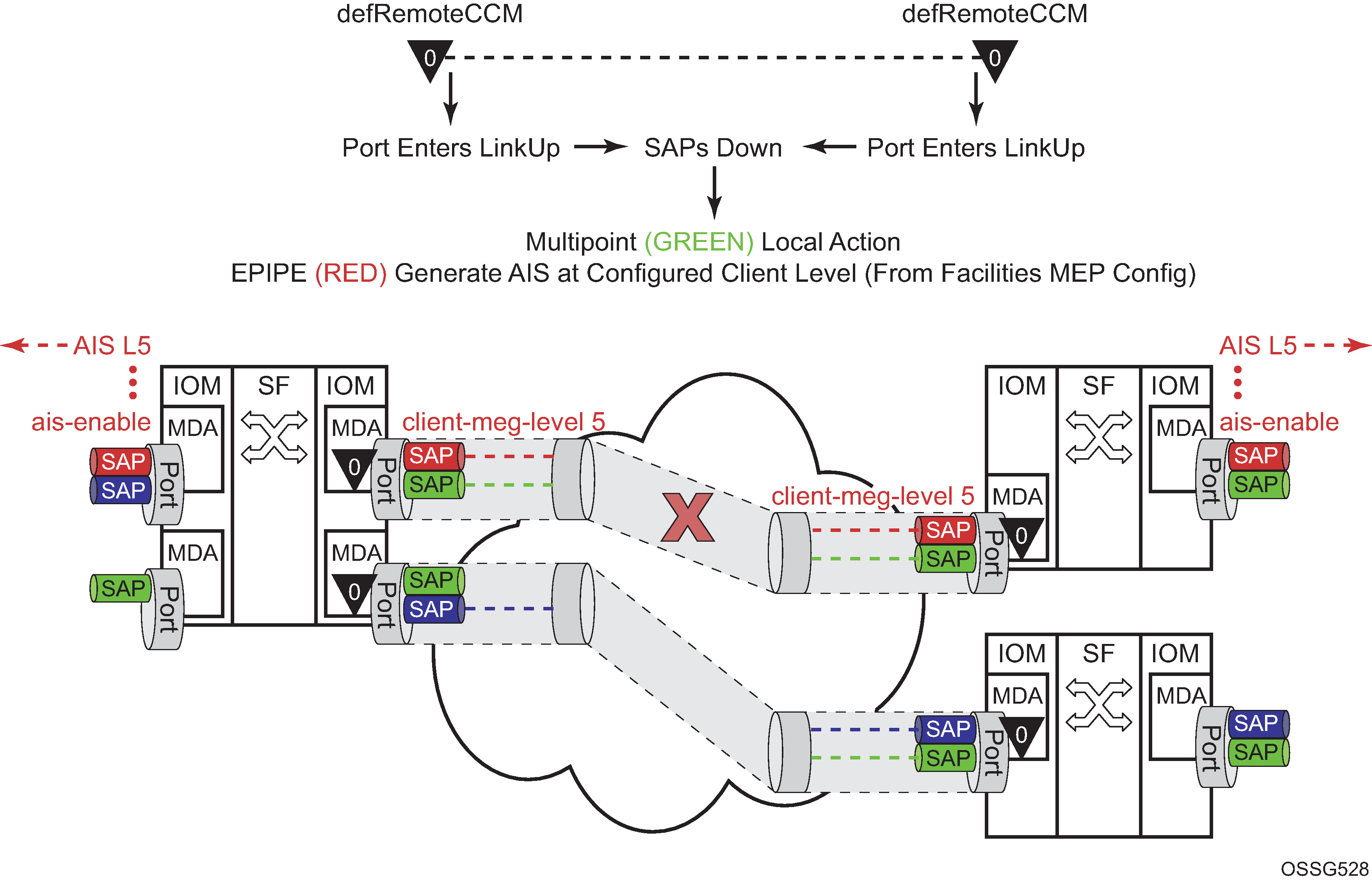
When a port enters the link up operational state because of ETH-CFM, the MEP continues to transmit and receive to properly clear the condition. However, when the port fails for reasons that are not specific to ETH-CFM, it stops transmit and receive functions until the condition is cleared. This is different from the behavior of a service MEP, because facility MEPs only support down MEPs, while some service-based MEPs support up and down MEPs. In the case of up MEPs, a single port failure may not prevent all the CCMs from egressing the node. So the operational method for service-based MEPs remains the same, continuing to increase the counter for CCM transmit in the event of port failure, regardless of the reason.
The following figure provides an example of how an ETH-CFM failure reacts with the various services that share that port. The green Epipe service generates AIS as a result of the port failure using the client-meg-level command configured on the port facility MEP. The multipoint service takes location configured action when the SAP transitions to the down operational state. The blue Epipe service is not affected by the port link operationally up state as a result of ETH-CFM fault.
A debounce function has been implemented to prevent notifying every port state change if a port bounces multiple times within a window. Up to four notifications are accepted in a 3-second window. If the third port state is a down state change, the fourth is ignored. If the fourth port state change is a down state change, it is processed. After that, no further state changes are accepted for the duration of the 3-second timer. This helps ensure that the port is not artificially held in the operationally up state when it is not in operation. Following the processing of that last port state change, the third or fourth, the latest state change is held and processed at the expiration of the 3 second hold timer.
Port-based facility MEPs are not allowed on a port that is configured with G.8031 Ethernet tunnels.
The following figure displays an example of how port-based MEPs and defect conditions translate into service awareness without service-based MEPs. The two nodes are aware that they are directly connected at the port level. However, they are unaware of the underlying cross connections that allow this to occur.
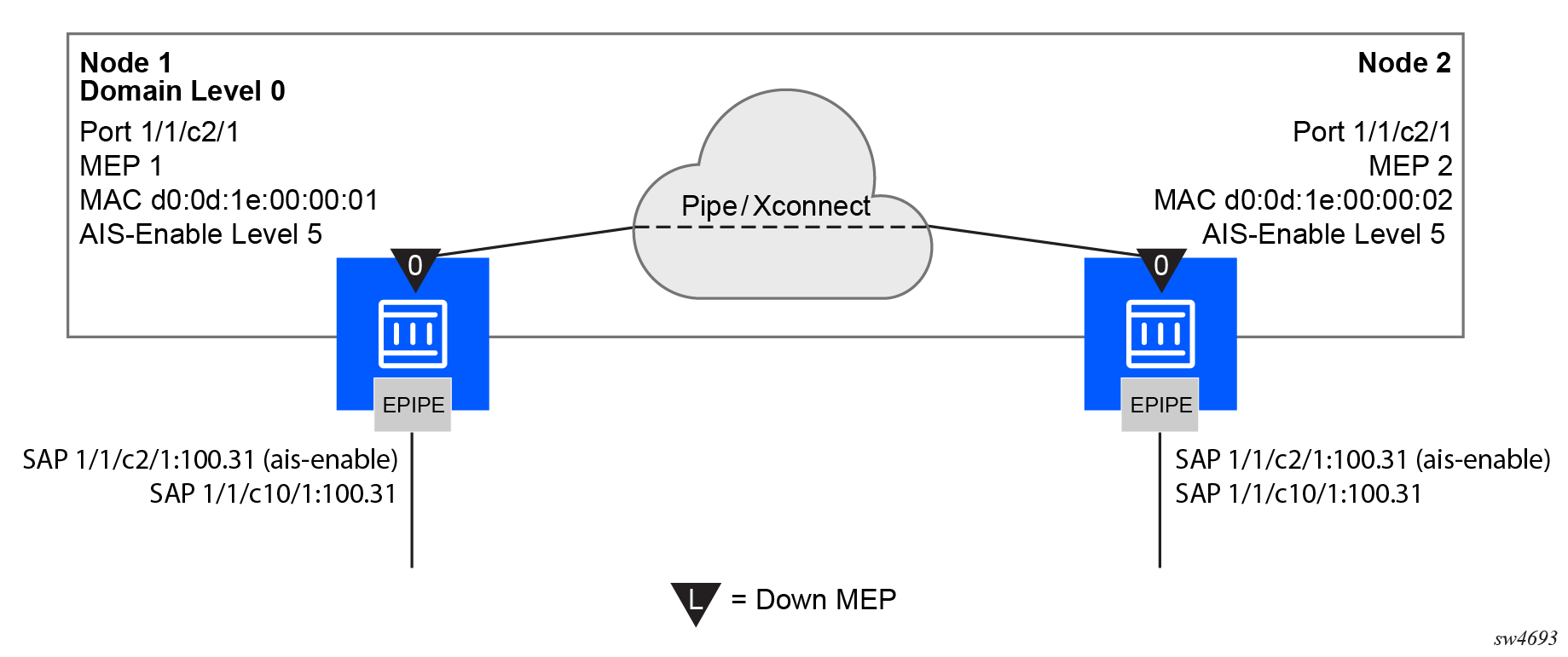
Use the following commands to configure port-based MEPs. When the MEP enters any defect state, an AIS is generated to any Epipe services that have AIS enabled under the sap eth-cfm hierarchy.
- MD-CLI
configure port ethernet eth-cfm mep facility-fault true configure port ethernet eth-cfm mep ais client-meg-level - classic
CLI
configure port ethernet eth-cfm mep facility-fault
configure port ethernet eth-cfm mep ais-enable client-meg-level
Node1 configuration (MD-CLI)
[ex:/configure eth-cfm]
A:admin@node-1# info
    domain "10" {
        level 0
        format none
        association "1" {
            icc-based "FacilityPort0"
            ccm-interval 1s
            remote-mep 2 {
            }
        }
    }

[ex:/configure port 1/1/c2/1]
A:admin@node-1# info
    admin-state enable
    ethernet {
        mode access
        encap-type qinq
        eth-cfm {
            mep md-admin-name "10" ma-admin-name "1" mep-id 1 {
                admin-state enable
                mac-address d0:0d:1e:00:00:01
                ccm true
                facility-fault true
                ais {
                    client-meg-level [5]
                }
            }
        }
    }
[ex:/configure service epipe "7"]
A:admin@node-1# info
    sap 1/1/c2/1:100.31 {
        eth-cfm {
            ais true
        }
    }
    sap 1/1/c10/1:100.31 {
    }
Node1 configuration (classic CLI)
A:node-1>config>eth-cfm# info
----------------------------------------------
        domain 10 format none level 0
            association 1 format icc-based name "FacilityPort0"
                ccm-interval 1
                remote-mepid 2
            exit
        exit
----------------------------------------------

A:node-1>config>port# info
----------------------------------------------
        ethernet
            mode access
            encap-type qinq
            eth-cfm
                mep 1 domain 10 association 1
                    ais-enable
                        client-meg-level 5
                    exit
                    facility-fault
                    ccm-enable
                    mac-address d0:0d:1e:00:00:01
                    no shutdown
                exit
            exit
        exit
        no shutdown
----------------------------------------------

A:node-1>config>service>epipe# info
----------------------------------------------
            sap 1/1/c2/1:100.31 create
                eth-cfm
                    ais-enable
                exit
            exit
            sap 1/1/c10/1:100.31 create
            exit
            no shutdown
----------------------------------------------
Node2 configuration (MD-CLI)
[ex:/configure eth-cfm]
A:admin@node-2# info
    domain "10" {
        level 0
        format none
        association "1" {
            icc-based "FacilityPort0"
            ccm-interval 1s
            remote-mep 1 {
            }
        }
    }
[ex:/configure port 1/1/c2/1]
A:admin@node-2# info
    admin-state enable
    ethernet {
        mode access
        encap-type qinq
        eth-cfm {
            mep md-admin-name "10" ma-admin-name "1" mep-id 2 {
                admin-state enable
                mac-address d0:0d:1e:00:00:02
                ccm true
                facility-fault true
                ais {
                    client-meg-level [5]
                }
            }
        }
    }
[ex:/configure service epipe "7"]
A:admin@node-2# info
    sap 1/1/c2/1:100.31 {
        eth-cfm {
            ais true
        }
    }
    sap 1/1/c10/1:100.31 {
    }
Node2 configuration (classic CLI)
A:node-2>config>eth-cfm# info
----------------------------------------------
        domain 10 format none level 0
            association 1 format icc-based name "FacilityPort0"
                ccm-interval 1
                remote-mepid 1
            exit
        exit
----------------------------------------------

A:node-2>config>port# info
----------------------------------------------
        ethernet
            mode access
            encap-type qinq
            eth-cfm
                mep 2 domain 10 association 1
                    ais-enable
                        client-meg-level 5
                    exit
                    facility-fault
                    ccm-enable
                    mac-address d0:0d:1e:00:00:02
                    no shutdown
                exit
            exit
        exit
        no shutdown
----------------------------------------------

A:node-2>config>service>epipe# info
----------------------------------------------
            sap 1/1/c2/1:100.31 create
                eth-cfm
                    ais-enable
                exit
            exit
            sap 1/1/c10/1:100.31 create
            exit
            no shutdown
----------------------------------------------
There are two different fault levels to consider: Port State/Operational State driven by the low-priority-defect setting and the generation of AIS driven by the defect state for the MEP.
If the low-priority-defect is left at the default macRemErrXcon setting, port state may not match on both nodes. If a unidirectional failure is introduced for port-based MEPs, RDI is received on one of the nodes and the other node reports and reacts to RemoteCCM (timeout). As the RDI defect is below the default low-priority-defect in priority, the port and port state remains operationally up. The MEP that has timed out the peer MEP takes port-level action because this defect is higher in priority than the default low-priority-defect. The port state is recorded as Link Up and the Port is operationally down with a "Reason Down: ethCfmFault". To avoid this inconsistency, set the low-priority-defect command to detect unidirectional failures using the allDef option.
The following show commands reveal the preceding condition within the network. In this example, Node 1 is receiving RDI and Node 2 has timed out its peer MEP.
Node1 outputs
The following outputs display information for the Node1 example configuration.
Use the following command to display port information.
show portNode1 port output
===============================================================================
Ports on Slot 1
===============================================================================
Port        Admin Link Port    Cfg  Oper LAG/ Port Port Port   C/QS/S/XFP/
Id          State      State   MTU  MTU  Bndl Mode Encp Type   MDIMDX
-------------------------------------------------------------------------------
...
1/1/c2/1       Up    Yes  Up      1522 1522    - accs qinq xcme
...
Use the following command to display information for a specific port.
show port 1/1/c2/1Node1 output for a specific port
===============================================================================
Ethernet Interface
===============================================================================
Description        : 10/100/Gig Ethernet SFP
Interface          : 1/1/c2/1                      Oper Speed       : 1 Gbps
Link-level         : Ethernet                   Config Speed     : 1 Gbps
Admin State        : up                         Oper Duplex      : full
Oper State         : up                         Config Duplex    : full
Physical Link      : Yes                        MTU              : 1522
...
Use the following command to display the maintenance endpoint, maintenance domain, and maintenance association information.
show eth-cfm mep 1 domain 10 association 1Node1 MEP configuration information output
===============================================================================
Eth-Cfm MEP Configuration Information
===============================================================================
Md-index           : 10                       Direction         : Down
Ma-index           : 1                        Admin             : Enabled
MepId              : 1                        CCM-Enable        : Disabled
Port               : 1/1/c2/1              VLAN              : 0
Description        : (Not Specified)
FngState           : fngReset                 ControlMep        : False
LowestDefectPri    : macRemErrXcon            HighestDefect     : none
Defect Flags       : bDefRDICCM
Mac Address        : d0:0d:1e:00:00:01        ControlMep        : False
CcmLtmPriority     : 7
CcmTx              : 1481                     CcmSequenceErr    : 0
Fault Propagation  : disabled                 FacilityFault     : Notify
MA-CcmInterval     : 1                        MA-CcmHoldTime    : 0ms
Eth-1Dm Threshold  : 3(sec)                   MD-Level          : 0
Eth-Ais:           : Enabled                  Eth-Ais Rx Ais:   : No
Eth-Ais Tx Priorit*: 7                        Eth-Ais Rx Interv*: 1
Eth-Ais Tx Interva*: 1                        Eth-Ais Tx Counte*: 3019
Eth-Ais Tx Levels  : 5
Eth-Tst:           : Disabled
...
Use the following command to display ETH-CFM facility information.
show service sap-using eth-cfm facilityNode1 ETH-CFM facility information output
===============================================================================
Service ETH-CFM Facility Information
===============================================================================
SapId             SvcId                          SAP AIS  SAP Tunnel SVC Tunnel
                                                          Fault      Fault
-------------------------------------------------------------------------------
1/1/c2/1:100.31      100                            Enabled  Accept     Ignore
-------------------------------------------------------------------------------
No. of Facility SAPs: 1
===============================================================================
Node2 outputs
The following outputs display information for the Node2 example configuration.
Use the following command to display port information.
show portNode2 port output
===============================================================================
Ports on Slot 1
===============================================================================
Port        Admin Link Port    Cfg  Oper LAG/ Port Port Port   C/QS/S/XFP/
Id          State      State   MTU  MTU  Bndl Mode Encp Type   MDIMDX
-------------------------------------------------------------------------------
...
1/1/c2/1       Up    Yes  Link Up 1522 1522    - accs qinq xcme
...
Use the following command to display information for a specific port.
show port 1/1/2Node2 output for a specific port
==============================================================================
Ethernet Interface
===============================================================================
Description        : 10/100/Gig Ethernet SFP
Interface          : 1/1/c2/1                   Oper Speed       : N/A
Link-level         : Ethernet                   Config Speed     : 1 Gbps
Admin State        : up                         Oper Duplex      : N/A
Oper State         : down                       Config Duplex    : full
Reason Down        : ethCfmFault
Physical Link      : Yes                        MTU              : 1522
...
Use the following command to display information for the specified maintenance endpoint, maintenance domain, and maintenance association.
show eth-cfm mep 2 domain 10 association 1Node2 MEP configuration information output
===============================================================================
Eth-Cfm MEP Configuration Information
===============================================================================
Md-index           : 10                       Direction         : Down
Ma-index           : 1                        Admin             : Enabled
MepId              : 2                        CCM-Enable        : Enabled
Port               : 1/1/c2/1                 VLAN              : 0
Description        : (Not Specified)
FngState           : fngDefectReported        ControlMep        : False
LowestDefectPri    : macRemErrXcon            HighestDefect     : defRemoteCCM
Defect Flags       : bDefRemoteCCM
Mac Address        : d0:0d:1e:00:00:02        ControlMep        : False
CcmLtmPriority     : 7
CcmTx              : 5336                     CcmSequenceErr    : 0
Fault Propagation  : disabled                 FacilityFault     : Notify
MA-CcmInterval     : 1                        MA-CcmHoldTime    : 0ms
Eth-1Dm Threshold  : 3(sec)                   MD-Level          : 0
Eth-Ais:           : Enabled                  Eth-Ais Rx Ais:   : No
Eth-Ais Tx Priorit*: 7                        Eth-Ais Rx Interv*: 1
Eth-Ais Tx Interva*: 1                        Eth-Ais Tx Counte*: 3515
Eth-Ais Tx Levels  : 5
Eth-Tst:           : Disabled
...
Use the following command to display ETH-CFM facility information.
show service sap-using eth-cfm facilityNode2 ETH-CFM facility information output
===============================================================================
Service ETH-CFM Facility Information
===============================================================================
SapId             SvcId                          SAP AIS  SAP Tunnel SVC Tunnel
                                                          Fault      Fault
-------------------------------------------------------------------------------
1/1/c2/1:100.31      100                            Enabled  Accept     Ignore
-------------------------------------------------------------------------------
No. of Facility SAPs: 1
===============================================================================
Router interface MEP
MEPs and associated on-demand troubleshooting functions act as router interfaces that are part of the base routing instance. This feature allows the user to verify Layer 2 transport that connects the Layer 3 interfaces.
Router interfaces MEPs are supported for all router interface instances (null port 1/1/1, dot1q port 1/1/3:vid, null LAG-lag-id and dot1q LAG-lag-id:vid).
The following figure shows how a router facility MEP can be configured on a routed interface in the base router instance.
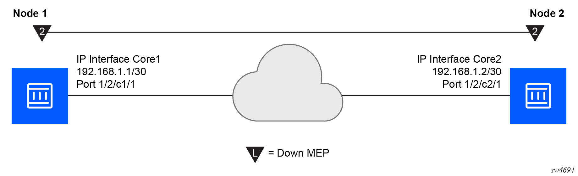
ETH-CFM tools for proactive management (ETH-CC), troubleshooting (Loopback, Linktrace, and so on), and profiling (Delay Measurement, and so on) are supported. The configuration and some ETH-CFM test commands are shown for Node1 (on the left in the preceding figure). Following the on-demand test output, the configuration for Node 2 is included for completeness, without repeating the on-demand tests.
Node1 configuration (MD-CLI)
[ex:/configure port 1/2/c1/1]
A:admin@node-1# info
    admin-state enable

[ex:/configure eth-cfm]
A:admin@node-1# info
    domain "2" {
        level 2
        format none
        association "2" {
            icc-based "FacilityRtr01"
        }
    }

[ex:/configure router "Base"]
A:admin@node-1# info
    interface "Core1" {
        port 1/2/c1/1
        eth-cfm {
            mep md-admin-name "2" ma-admin-name "2" mep-id 1 {
                admin-state enable
                mac-address d0:0d:1e:00:00:01
            }
        }
        ipv4 {
            primary {
                address 192.168.1.1
                prefix-length 30
            }
        }
    }
Node1 configuration (classic CLI)
A:node-1>config>port# info
----------------------------------------------
        ethernet
        exit
        no shutdown
----------------------------------------------

A:node-1>config>eth-cfm# info
----------------------------------------------
        domain 2 format none level 2
            association 2 format icc-based name "FacilityRtr01"
            exit
        exit
----------------------------------------------

A:node-1>config>router# info
#--------------------------------------------------
echo "IP Configuration"
#--------------------------------------------------
        interface "Core1"
            address 192.168.1.1/30
            port 1/2/c1/1
            eth-cfm
                mep 1 domain 2 association 2
                    mac-address d0:0d:1e:00:00:01
                    no shutdown
                exit
            exit
        exit
        interface "system"
        exit
----------------------------------------------
Use the following command to display CFM facility information stack information for all router interfaces.
show eth-cfm cfm-stack-table facility all-router-interfacesCFM facility information output
===============================================================================
CFM Stack Table Defect Legend:
R = Rdi, M = MacStatus, C = RemoteCCM, E = ErrorCCM, X = XconCCM, A = AisRx

===============================================================================
CFM Facility Interface Stack Table
===============================================================================
Interface          Lvl Dir  Md-index   Ma-index   MepId  Mac-address     Defect
-------------------------------------------------------------------------------
Core1                2 Down          2          2    1 d0:0d:1e:00:00:01 ------
===============================================================================
Use the following command to display CFM facility interface stack information for all router interfaces.
show eth-cfm cfm-stack-table facility all-router-interfacesCFM facility interface stack information output
===============================================================================
CFM Stack Table Defect Legend:
R = Rdi, M = MacStatus, C = RemoteCCM, E = ErrorCCM, X = XconCCM, A = AisRx

===============================================================================
CFM Facility Interface Stack Table
===============================================================================
Interface          Lvl Dir  Md-index   Ma-index   MepId  Mac-address     Defect
-------------------------------------------------------------------------------
Core1                2 Down          2          2    1 d0:0d:1e:00:00:01 ------
===============================================================================

# oam eth-cfm loopback d0:0d:1e:00:00:02 mep 1 domain 2 association 2
 send-count 5
Eth-Cfm Loopback Test Initiated: Mac-Address: d0:0d:1e:00:00:02, out service: 0
Sent 5 packets, received 5 packets [0 out-of-order, 0 Bad Msdu]

# oam eth-cfm linktrace d0:0d:1e:00:00:02 mep 1 domain 2 association
2
Index Ingress Mac          Egress Mac           Relay      Action
----- -------------------- -------------------- ---------- ----------
1     D0:0D:1E:00:00:02    00:00:00:00:00:00    n/a        terminate
----- -------------------- -------------------- ---------- ----------
No more responses received in the last 6 seconds.

# oam eth-cfm two-way-delay-test d0:0d:1e:00:00:02 mep 1 domain 2 association 2
Two-Way-Delay-Test Response:
Delay 1130 microseconds        Variation 63 microseconds

# oam eth-cfm two-way-delay-test d0:0d:1e:00:00:02 mep 1 domain 2 association 2
Two-Way-Delay-Test Response:
Delay 1218 microseconds        Variation 88 microseconds
Node2 configuration (MD-CLI)
[ex:/configure port 1/2/c2/1]
A:admin@node-2# info
    admin-state enable

[ex:/configure eth-cfm]
A:admin@node-2# info
    domain "2" {
        level 2
        format none
        association "2" {
            icc-based "FacilityRtr01"
        }
    }

[ex:/configure router "Base"]
A:admin@node-2# info
    interface "Core2" {
        port 1/2/c2/1
        eth-cfm {
            mep md-admin-name "2" ma-admin-name "2" mep-id 2 {
                admin-state enable
                mac-address d0:0d:1e:00:00:02
            }
        }
        ipv4 {
            primary {
                address 192.168.1.2
                prefix-length 30
            }
        }
    }
Node2 configuration (classic CLI)
A:node-2>config>port# info
----------------------------------------------
        ethernet
        exit
        no shutdown
----------------------------------------------

A:node-2>config>eth-cfm# info
----------------------------------------------
        domain 2 format none level 2
            association 2 format icc-based name "FacilityRtr01"
            exit
        exit
----------------------------------------------

A:node-2>config>router# info
#--------------------------------------------------
echo "IP Configuration"
#--------------------------------------------------
        interface "Core2"
            address 192.168.1.2/30
            port 1/2/c2/1
            eth-cfm
                mep 2 domain 2 association 2
                    mac-address d0:0d:1e:00:00:02
                    no shutdown
                exit
            exit
        exit
        interface "system"
        exit
----------------------------------------------
ETH-CFM and MC-LAG
By default, ETH-CFM MEPs and MC-LAG operate independently. Nokia recommends users do not enable fault propagation when the default behavior is in use. A global command allows ETH-CFM to track the state of MC-LAG for MPs configured on MC-LAG ports. This feature does not allow MEPs to influence the MC-LAG state. Because the MP relies on the underlying MC-LAG construct, consider the correct MC-LAG design and deployment. The state of the MC-LAG can be reflected in the state of the MPs, which are configured on SAPs that are part MC-LAGs. For example, a SAP on a LAG that is part of an MC-LAG configuration can behave in a manner that more appropriately represents the MC-LAG.
ETH-CFM and MC-LAG default behavior
ETH-CFM MPs track the SAPs, bindings, and facility independently. Therefore, when an MP is configured on a SAP that is not operationally up because of an MC-LAG ETH-CFM defect, the system can raise conditions for what could be considered normal conditions.
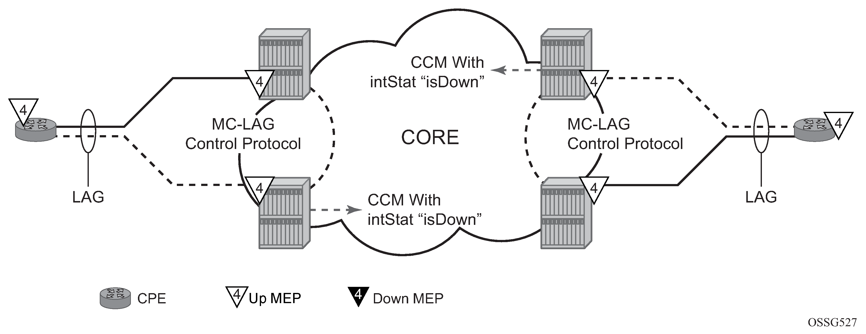
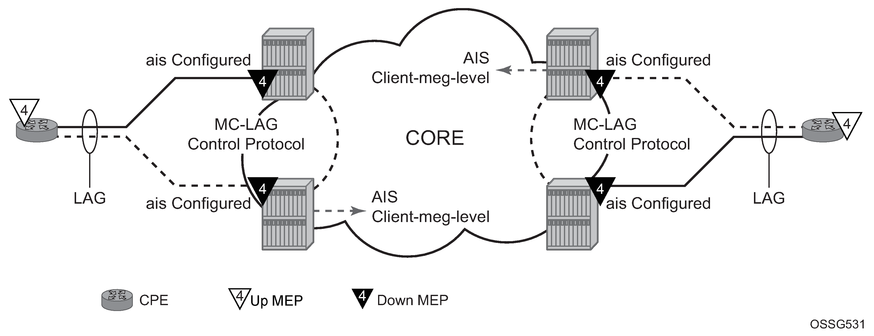
The following figure shows the default behavior for a point-to-point service without regard for the MC-LAG. In the following case, the two up MEPs operating at level 4 on the affected SAPs set the Interface-Status-TLV bit in the ETH-CC header to represent the isDown condition, assuming ETH-CC is executing between the peer MEPs. This is the correct action based on the ETH-CFM perspective; SAPs are operationally down.
A similar condition exists if a user configures down MEPs on the SAPs that are operationally down. The following figure shows how the same service configured with down MEPs would generate AIS, if enabled, toward the remote client at the configured client-meg-level, in the reverse direction of the MEP. This is also the correct behavior from the perspective of ETH-CFM.
Linking ETH-CFM to MC-LAG state
There are benefits to allowing ETH-CFM to understand the state of MC-LAG and adjusting the behavior of the MP (MEP) according to that state.
MC-LAG represents the two upstream nodes as a single system to the node terminating in a standard LAG. Linking the ETH-CFM MPs to the state of the MC-LAG allows the user to configure MPs across the two nodes that appear the same. Under the default configuration, this introduces various defect conditions and event conditions. However, when ETH-CFM tracks the state of the MC-LAG, the MPs perform a role that represents the state of the resiliency mechanism.
Use the following system-wide command to enable MEPs to track the state of MC-LAG and allow MEPs on the standby MC-LAG to act administratively down:
- MD-CLI
configure system eth-cfm redundancy mc-lag standby-mep true - classic
CLI
configure eth-cfm redundancy mc-lag standby-mep-shutdown
- terminating
- generating
- responding to
- processing
An MP that is on the standby MC-LAG node enters a pseudo-shutdown state. These MPs terminate all ETH-CFM packets that are part of the regular interception process, but do not process them. The router silently discards them. Also, an MP that exists on a standby MC-LAG system does not generate any ETH-CFM packets. The router blocks all proactive and on-demand functions on the standby MC-LAG node. When scheduled tests are executed through SAA, these tests attempt to execute. The tests record failures as a result of the MEP state. These failures are not representative of the network.
This feature relies on the correct configuration, design, and deployment of the MC-LAG protocol. There are numerous optimizations and command options that are available as part of the MC-LAG functions. For example, by default, when a currently active MC-LAG port transitions to standby, by any means including manual user intervention, the remote node terminating the standard LAG sees the LAG transition because all ports in the LAG are down for an instance in time. This is standard LAG behavior and does not change as a result of the linkage of the MP state to the MC-LAG state. This transition causes the propagation of faults for MEPs configured on that node.
ETH-CFM registers a fault propagation delay timer equal to the propagate hold time configured using the following command (default of 1s):
- MD-CLI
configure system eth-cfm redundancy mc-lag propagate-hold-time - classic
CLI
configure eth-cfm redundancy mc-lag propagate-hold-time
The fault propagation delay timer delays notification of an event that may be the result of an MC-LAG failover. This allows the system time to coordinate events and triggers that together represent the MC-LAG transition from active to standby.
A fixed timer value of 1-second delays an up MEP from announcing a SAP down condition, through the CCM Interface-Status-TLV bits. ETH-CFM maintains a status of last sent to the peer of the up MEPs. When the SAP transitions either to up or down, that fault is held for the fixed 1-second interval and the last Interface-Status-TLV bits are set based on the previous transmission. If the condition, different from the previous sent, still exists at the end of the 1-second fixed timer, and when the next CCM interval expires, the representative value of the SAP is sent in the Interface-Status-TLV. These two timers help to smooth out network transitions at the cost of propagation and clearing of faults.
When a node with ETH-CFM linked to MC-LAG is transitioning from standby to active, ETH-CFM assumes no underlying conditions exist for any of the SAPs that are now part of the newly activated MC-LAG. The initial notification to an up MEP peer does not include any faults. It assumes that the transitioning SAPs are stabilizing as the switchover proceeds. The fixed 1-second timer starts, and a second CCM PDU (based on the up MEPs interval) is sent without any recognition of potential fault on the SAP. However, after the expiration of the fixed timer, and on the next CCM interval, the Interface-Status-TLV represents the state of the SAP.
In scaled environments, configure the propagation-hold-time and the CCM intervals to achieve the needed goals. If these timers are set too aggressively, the router may generate fault and defect conditions during times of network stabilization. Carefully consider the use of fault propagation and AIS transmission in environments where MC-LAG protection mechanisms are deployed. Timer values do not guarantee that transitional state information is not propagated to the peer. The propagation of such states may be more taxing and disruptive than allowing the transmission states to complete. For example, if AIS generation is used, use a 60-second AIS interval to avoid advertising the transitional state.
AIS generation is paced in a first come, first serve model not to exceed the system capability. Scale is dependent on the type of system. If AIS is configured in an MC-LAG solution the user must make sure that the same MEPs on each system are configured to generate AIS, and this number does not exceed the maximum. This requires the user to configure both nodes with the same MEPs that can generate AIS and not exceed the system capacity. If the nodes are configured differently, or exceed the system scale, a transition may see a different set of MEPs outpace the AIS of the original set of MEPs. There is no synchronization of the AIS state across nodes.
Administrative functions, like administratively down, are special cases. When the administrative state changes from up to down, the timer is bypassed and communication from ETH-CFM is immediate.
When an MP is configured in an MC-LAG environment, Nokia recommends that each aspect of the MP be configured the same, including MAC address. Also, both nodes participating in the MC-LAG, which require this functionality, should include the following global command to avoid unpredictable behavior:
- MD-CLI
configure system eth-cfm redundancy mc-lag standby-mep true - classic
CLI
configure eth-cfm redundancy mc-lag standby-mep-shutdown
In summary, a SAP with ETH-CFM tracking the state of the MC-LAG represents the state of the MC-LAG. MPs configured on the standby MC-LAG ports enter a state similar to being administratively disabled. MPs on the MC-LAG ports on the active MC-LAG ports perform all normal processing.
The following figure shows how MEPs can be linked to the MC-LAG state. In this example, a service MEP is created on the LAG SAP on NODE1 within service VPLS 100. The MEPs configured on the MC-LAG nodes within service 100 are both configured the same. Both MEPs use the same MEP-ID and the same MAC address.
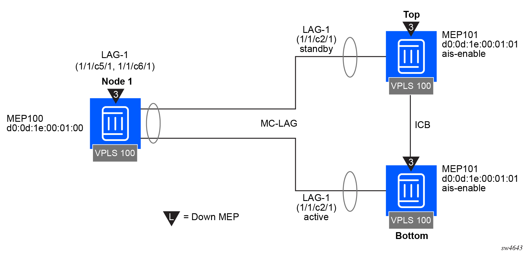
Only one of the MEPs on the MC-LAG nodes is active for VPLS service 100. The other MEP is in a shutdown mode, so that even when the MC-LAG is in standby and the port state is link up, the MEP is in a pseudo-shutdown state.
The following configuration example is not meant to provide all possible MC-LAG configuration statements to tune each provider’s network. It does provide a base configuration to demonstrate the ETH-CFM feature.
Node1 configuration (MD-CLI)
[ex:/configure port 1/1/c5/1]
A:admin@node-1# info
    ethernet {
        autonegotiate limited
        mode access
        encap-type qinq
    }

[ex:/configure port 1/1/c6/1]
A:admin@node-1# info
    ethernet {
        autonegotiate limited
        mode access
        encap-type qinq
    }

[ex:/configure lag "lag-1"]
A:admin@node-1# info
    admin-state enable
    encap-type qinq
    mode access
    hold-time-down 10
    lacp {
        mode active
        administrative-key 32768
    }
    access {
        adapt-qos {
            mode link
        }
    }
    port 1/1/c5/1 {
    }
    port 1/1/c6/1 {
    }

[ex:/configure eth-cfm]
A:admin@node-1# info
...
    domain "3" {
        level 3
        format none
        association "1" {
            icc-based "03-0000000100"
            ccm-interval 1s
            bridge-identifier "100" {
            }
            remote-mep 101 {
            }
        }
    }
[ex:/configure service vpls "100"]
A:admin@node-1# info
...
    stp {
        admin-state disable
    }
    sap 1/1/c2/1:100.100 {
    }
    sap lag-1:100.100 {
        eth-cfm {
            mep md-admin-name "3" ma-admin-name "1" mep-id 100 {
                mac-address d0:0d:1e:00:01:00
                ccm true
            }
        }
    }
Node1 configuration (classic CLI)
A:node-1>config>port# info (both ports)
----------------------------------------------
        ethernet
            mode access
            encap-type qinq
            autonegotiate limited
        exit
        no shutdown
----------------------------------------------

A:node-1>config>lag# info
----------------------------------------------
     mode access
        encap-type qinq
        access
            adapt-qos link
        exit
        port 1/1/c5/1
        port 1/1/c6/1
        lacp active administrative-key 32768
        hold-time down 10
        no shutdown
----------------------------------------------

A:node-1>config>eth-cfm# info
----------------------------------------------
        domain 3 format none level 3
            association 1 format icc-based name "03-0000000100"
                bridge-identifier bridge-name 100
                exit
            ccm-interval 1
            remote-mepid 101
            exit
        exit
----------------------------------------------

A:node-1>config>service>vpls# info
----------------------------------------------
            stp
                shutdown
            exit
            sap 1/1/c2/1:100.100 create
            exit
            sap lag-1:100.100 create
                eth-cfm
                    mep 100 domain 3 association 1
                        ccm-enable
                        mac-address d0:0d:1e:00:01:00
                        no shutdown
                    exit
                exit
            exit
            no shutdown
----------------------------------------------
Top (MC-LAG Standby) configuration (MD-CLI)
[ex:/configure port 1/1/c2/1]
A:admin@node-top# info
    ethernet {
        autonegotiate limited
        mode access
        encap-type qinq
    }

[ex:/configure lag "lag-1"]
A:admin@node-top# info
    admin-state enable
    encap-type qinq
    mode access
    hold-time-down 10
    lacp {
        mode active
        administrative-key 32768
    }
    access {
        adapt-qos {
            mode link
        }
    }
    port 1/1/c2/1 {
    }

[ex:/configure router "Base"]
A:admin@node-top# info
    interface "Core2" {
        port 1/1/c2/1
        ipv4 {
            primary {
                address 192.168.1.2
                prefix-length 30
            }
        }
    }

[ex:/configure redundancy]
A:admin@node-top# info
    synchronize boot-env
    multi-chassis {
        peer 192.168.1.1 {
            admin-state enable
            source-address 192.168.1.2
            mc-lag {
                admin-state enable
            lag "lag-1" {
                    lacp-key 1
                    system-id 00:00:00:00:00:01
                    system-priority 100
                }
            }
        }
    }

[ex:/configure eth-cfm]
A:admin@node-top# info
    domain "3" {
        level 3
        format none
        association "1" {
            icc-based "03-0000000100"
            ccm-interval 1s
            bridge-identifier "100" {
            }
            remote-mep 100 {
            }
        }
    }

[ex:/configure system eth-cfm]
A:admin@node-top# info
    redundancy {
        mc-lag {
            standby-mep true
        }
    }

[ex:/configure service vpls "100"]
A:admin@node-top# info
...
    stp {
        admin-state disable
    }
    sap lag-1:100.100 {
        eth-cfm {
            mep md-admin-name "3" ma-admin-name "1" mep-id 101 {
                mac-address d0:0d:1e:00:01:01
                ccm true
            }
        }
    }
Top (MC-LAG Standby) configuration (classic CLI)
A:node-top>config>port# info
----------------------------------------------
        ethernet
            mode access
            encap-type qinq
            autonegotiate limited
        exit
        no shutdown
----------------------------------------------

A:node-top>config>lag# info
----------------------------------------------
        mode access
        encap-type qinq
        access
            adapt-qos link
        exit
        port 1/1/c2/1
        lacp active administrative-key 32768
        no shutdown
----------------------------------------------

A:node-top>config>router# info
#--------------------------------------------------
echo "IP Configuration"
#--------------------------------------------------
        interface "Core2"
            address 192.168.1.2/30
            port 1/1/c2/1
        exit
        interface "system"
        exit
----------------------------------------------

A:node-top>config>redundancy# info
----------------------------------------------
        multi-chassis
            peer 192.168.1.1 create
                source-address 192.168.1.2
                mc-lag
                    lag 1 lacp-key 1 system-id 00:00:00:00:00:01 system-priority
 100
                    no shutdown
                exit
                no shutdown
            exit
        exit
        synchronize boot-env
----------------------------------------------

A:node-top>config>eth-cfm# info
----------------------------------------------
        domain 3 format none level 3
            association 1 format icc-based name "03-0000000100"
                bridge-identifier bridge-name 100
                exit
                ccm-interval 1
                remote-mepid 100
            exit
        exit
        redundancy
            mc-lag
                standby-mep-shutdown
            exit
        exit
----------------------------------------------

A:node-top>config>service>vpls# info
----------------------------------------------
            stp
                shutdown
            exit
            sap lag-1:100.100 create
                eth-cfm
                    mep 101 domain 3 association 1
                        exit
                        ccm-enable
                        mac-address d0:0d:1e:00:01:01
                        no shutdown
                    exit
                exit
            exit
            no shutdown
----------------------------------------------
Use the following command to show LAG information for the Top (standby) configuration.
show lag 1Top (standby) LAG output
===============================================================================
Lag Data
===============================================================================
Lag-id         Adm     Opr     Port-Threshold   Up-Link-Count   MC Act/Stdby
-------------------------------------------------------------------------------
1              up      down    0                0               standby
===============================================================================
Use the following command to show port information.
show portTop (standby) port output
===============================================================================
Ports on Slot 1
===============================================================================
Port        Admin Link Port    Cfg  Oper LAG/ Port Port Port   C/QS/S/XFP/
Id          State      State   MTU  MTU  Bndl Mode Encp Type   MDIMDX
-------------------------------------------------------------------------------
...
1/1/c2/1       Up    Yes  Link Up 1522 1522    1 accs qinq xcme
...
==========================================================================
Bottom (MC-LAG Active) configuration (MD-CLI)
[ex:/configure port 1/1/c2/1]
A:admin@node-bottom# info
    ethernet {
        autonegotiate limited
        mode access
        encap-type qinq
    }

[ex:/configure lag "lag-1"]
A:admin@node-bottom# info
    admin-state enable
    encap-type qinq
    mode access
    lacp {
        mode active
        administrative-key 32768
    }
    access {
        adapt-qos {
            mode link
        }
    }
    port 1/1/c2/1 {
    }

[ex:/configure router "Base"]
A:admin@node-bottom# info
    interface "Core1" {
        port 1/1/c2/1
        ipv4 {
            primary {
                address 192.168.1.1
                prefix-length 30
            }
        }
    }

[ex:/configure redundancy]
A:admin@node-bottom# info
    synchronize boot-env
    multi-chassis {
        peer 192.168.1.2 {
            admin-state enable
            source-address 192.168.1.1
            mc-lag {
                admin-state enable
                lag "lag-1" {
                    lacp-key 1
                    system-id 00:00:00:00:00:01
                    system-priority 100
                }
            }
        }
    }

[ex:/configure eth-cfm]
A:admin@node-bottom# info
    domain "3" {
        level 3
        format none
        association "1" {
            icc-based "03-0000000100"
            ccm-interval 1s
            bridge-identifier "100" {
            }
            remote-mep 100 {
            }
        }
    }


[ex:/configure system eth-cfm]
A:admin@node-bottom# info
    redundancy {
        mc-lag {
            standby-mep true
        }
    }

[ex:/configure service vpls "100"]
A:admin@node-bottom# info
...
    stp {
        admin-state disable
    }
    sap lag-1:100.100 {
        eth-cfm {
            mep md-admin-name "3" ma-admin-name "1" mep-id 101 {
                mac-address d0:0d:1e:00:01:01
                ccm true
            }
        }
    }
Bottom (MC-LAG Active) configuration (classic CLI)
A:node-bottom>config>port# info
----------------------------------------------
        ethernet
            mode access
            encap-type qinq
            autonegotiate limited
        exit
        no shutdown
----------------------------------------------

A:node-bottom>config>lag# info
----------------------------------------------
        mode access
        encap-type qinq
        access
            adapt-qos link
        exit
        port 1/1/c2/1
        lacp active administrative-key 32768
        no shutdown
----------------------------------------------

A:node-bottom>config>router# info
#--------------------------------------------------
echo "IP Configuration"
#--------------------------------------------------
        interface "Core1"
            address 192.168.1.1/30
            port 1/1/c2/1
        exit
        interface "system"
        exit
----------------------------------------------

A:node-bottom>config>redundancy# info
----------------------------------------------
        multi-chassis
            peer 192.168.1.2 create
                source-address 192.168.1.1
                mc-lag
                    lag 1 lacp-key 1 system-id 00:00:00:00:00:01 system-priority 100
                    no shutdown
                exit
                no shutdown
            exit
        exit
        synchronize boot-env
----------------------------------------------

A:node-bottom>config>eth-cfm# info
----------------------------------------------
        domain 3 format none level 3
            association 1 format icc-based name "03-0000000100"
                bridge-identifier bridge-name "100"
                exit
                ccm-interval 1
                remote-mepid 100
            exit
        exit
        redundancy
            mc-lag
                standby-mep-shutdown
            exit
        exit
----------------------------------------------

A:node-bottom>config>service>vpls# info
----------------------------------------------
            stp
                shutdown
            exit
            sap lag-1:100.100 create
                eth-cfm
                    mep 101 domain 3 association 1
                        exit
                        ccm-enable
                        mac-address d0:0d:1e:00:01:01
                        no shutdown
                    exit
                exit
            exit
            no shutdown
----------------------------------------------
Use the following command to show LAG information.
show lag 1Bottom (active) LAG output
===============================================================================
Lag Data
===============================================================================
Lag-id         Adm     Opr     Port-Threshold   Up-Link-Count   MC Act/Stdby
-------------------------------------------------------------------------------
1              up      up      0                1               active
===============================================================================
Use the following command to show port information.
show portBottom (active) LAG port output
===============================================================================
Ports on Slot 1
===============================================================================
Port        Admin Link Port    Cfg  Oper LAG/ Port Port Port   C/QS/S/XFP/
Id          State      State   MTU  MTU  Bndl Mode Encp Type   MDIMDX
-------------------------------------------------------------------------------
...
1/1/c2/1       Up    Yes  Up      1522 1522    1 accs qinq xcme
...
===============================================================================
Configuring ETH-CFM
Configuring ETH-CFM requires commands at two different hierarchy levels of the CLI.
The configuration under the configure eth-cfm context defines the domains, associations, and the applicable global configurations for each of those contexts, including the linkage to the service using the bridge-identifier command. After this configuration is complete, the Management Points (MPs) may be defined referencing the appropriate global context.
As described in the 7705 SAR OAM and Diagnostics Guide, MEPs can be implemented at the service or the facility level. The following examples describe how the ETH-CFM MPs are configured within the service hierarchy level. However, because of the wide range of features that the ITU-T has defined in recommendation Y.1731 (Fault Management, Performance Management and Protection Mechanisms), the features may be applied to other features and hierarchies. For example, Ethernet Ring Protection (G.8032) also makes use of various ETH-CFM functions.
The following is an example of how domains and associations can be constructed, illustrating how the different services are linked to the contexts.
Construction of domains and associations (MD-CLI)
[ex:/configure eth-cfm]
A:admin@node-2# info
    domain "3" {
        level 3
        format none
        association "1" {
            icc-based "03-0000000101"
            bridge-identifier "100" {
            }
        }
    }
    domain "4" {
        level 4
        format none
        association "1" {
            icc-based "04-0000000102"
            ccm-interval 60s
            bridge-identifier "100" {
            }
            remote-mep 200 {
            }
        }
    }
Construction of domains and associations (classic CLI)
A:node-2>config>eth-cfm# info
----------------------------------------------
        domain 3 format none level 3
            association 1 format icc-based name "03-0000000101"
                bridge-identifier 100
                exit
            exit
        exit
        domain 4 format none level 4
            association 1 format icc-based name "04-0000000102"
                bridge-identifier 100
                remote-mepid 200
                ccm-interval 60
                exit
            exit
        exit
The following configuration examples illustrate how different services use the domain and association configuration. An Epipe and VPLS service are shown in this example.
Configuration of the domain and association in different services (MD-CLI)
[ex:/configure service epipe "100"]
A:admin@node-2# info
    admin-state enable
    customer "1"
    sap 1/1/c2/1:100.31 {
        admin-state enable
        eth-cfm {
            mep md-admin-name "3" ma-admin-name "1" mep-id 111 {
                admin-state enable
                direction down
                mac-address d0:0d:1e:00:01:11
            }
        }
    }
    sap 1/1/c10/1:100.31 {
        admin-state enable
        eth-cfm {
            mep md-admin-name "4" ma-admin-name "1" mep-id 101 {
                admin-state enable
                direction up
                mac-address d0:0d:1e:00:01:01
                ccm true
            }
        }
    }

[ex:/configure service vpls "100"]
A:admin@node-2# info
    admin-state enable
    customer "1"
    sap 1/1/c2/1:100.31 {
        eth-cfm {
            mep md-admin-name "3" ma-admin-name "1" mep-id 111 {
                admin-state enable
                direction down
                mac-address d0:0d:1e:00:01:11
            }
        }
    }
    sap 1/1/c10/1:100.31 {
        eth-cfm {
            mep md-admin-name "4" ma-admin-name "1" mep-id 101 {
                admin-state enable
                direction up
                mac-address d0:0d:1e:00:01:01
                ccm true
            }
        }
    }
Configuration of the domain and association in different services (classic CLI)
A:node-2# configure service epipe 100 customer 1 create
A:node-2>config>service>epipe# info
----------------------------------------------
            sap 1/1/c2/1:100.31 create
                eth-cfm
                    mep 111 domain 3 association 1 direction down
                        no shutdown
                        mac-address d0:0d:1e:00:01:11
                    exit
                exit
                no shutdown
            exit
            sap 1/1/c10/1:100.31 create
                eth-cfm
                    mep 101 domain 4 association 1 direction up
                        ccm-enable
                        mac-address d0:0d:1e:00:01:01
                        no shutdown
                    exit
                exit
                no shutdown
            exit
            no shutdown
----------------------------------------------
A:node-2# configure service vpls 100 customer 1 create
A:node-2>config>service>vpls# info
----------------------------------------------
            sap 1/1/c2/1:100.31 create
                eth-cfm
                    mep 111 domain 3 association 1 direction down
                        mac-address d0:0d:1e:00:01:11
                        no shutdown
                    exit
                exit
            exit
            sap 1/1/c10/1:100.31 create
                eth-cfm
                    mep 101 domain 4 association 1 direction up
                        mac-address d0:0d:1e:00:01:01
                        ccm-enable
                        no shutdown
                    exit
                exit
            exit
            no shutdown
----------------------------------------------