System management
This chapter provides information about configuring basic system management parameters.
System management commands
System management commands allow you to configure basic system management functions, such as the system name, contact, router location and coordinates, naming objects, and CLLI code, as well as time zones, Network Time Protocol (NTP), Simple Network Time Protocol (SNTP) synchronization, Precision Time Protocol (PTP), and CRON.
On SR OS routers, it is possible to query the DNS server for IPv6 addresses. By default, the DNS names are queried for A-records only (address-preference is IPv4-only). If the address-preference is set to IPv6 first, the DNS server is queried for AAAA-records first, and if there is no successful reply, then A-records.
System information
This section describes the system information components.
Name
You can configure a name for the system device. The name is used in the prompt string. Only one system name can be configured. If multiple system names are configured the last one encountered overwrites the previous entry. Use the following command to configure the system name.
configure system nameContact
Use the contact command to specify the name of a system administrator, IT staff member, or other administrative entity.
Use the following command to configure the contact.
configure system contactLocation
Use the location command to specify the location of the device. For example, enter the city, building address, floor, room number, and so on, where the router is located.
Use the following command to configure the location.
configure system locationCoordinates
You can optionally configure the GPS location of the device. If the string contains special characters (#, $, spaces, and so on), the entire string must be enclosed within double quotes. Use the following command to configure the system coordinates.
configure system coordinatesNaming objects
Avoid configuring named objects with a name that starts with ‟_tmnx_” and with ‟_” in general.
Common language location identifier
A Common Language Location Identifier (CLLI) for the device is an 11-character standardized code string that uniquely identifies the geographic location of places and specific functional categories of equipment unique to the telecommunications industry. The CLLI code is stored in the Nokia Chassis MIB tmnxChassisCLLICode object.
The CLLI code can be any ASCII printable text string of up to 11 characters.
DNS security extensions
DNS Security (DNSSEC) Extensions are now implemented in the SR OS, allowing operators to configure DNS behavior of the router to evaluate whether the Authenticated Data bit was set in the response received from the recursive name server and to trust the response, or ignore it.
System time
Routers are equipped with a real-time system clock for timekeeping purposes. When set, the system clock always operates on Coordinated Universal Time (UTC), but the software has options for local time translation as well as system clock synchronization.
Time zones
Setting a time zone in SR OS allows for times to be displayed in the local time rather instead of UTC. SR OS has both user-defined and system-defined time zones.
A user-defined time zone has a user-assigned name of up to four printable ASCII characters in length and is unique from the system-defined time zones. For user-defined time zones, the offset from UTC is configured as well as any summer time adjustment for the time zone.
configure system time prefer-local-timeTime strings include the following:
- log filenames and log header information
- times in rollback information
- times in rollback and configuration files header information
- times related to CRON scripts
- times related to CRON scripts
- times in the event handler system
- times in NETCONF and gRPC date-and-time leafs
configure log log-id time-formatThe SR OS system-defined time zones are listed in the following table, which includes both time zones with and without daylight saving (summer) time adjustment.
| Acronym | Time zone name | UTC offset |
|---|---|---|
Europe: |
||
GMT |
Greenwich Mean Time |
UTC |
BST |
British Summer Time |
UTC +1 |
IST |
Irish Summer Time |
UTC +1* |
WET |
Western Europe Time |
UTC |
WEST |
Western Europe Summer Time |
UTC +1 |
CET |
Central Europe Time |
UTC +1 |
CEST |
Central Europe Summer Time |
UTC +2 |
EET |
Eastern Europe Time |
UTC +2 |
EEST |
Eastern Europe Summer Time |
UTC +3 |
MSK |
Moscow Time |
UTC +3 |
MSD |
Moscow Summer Time |
UTC +4 |
US and Canada: |
||
AST |
Atlantic Standard Time |
UTC -4 |
ADT |
Atlantic Daylight Time |
UTC -3 |
EST |
Eastern Standard Time |
UTC -5 |
EDT |
Eastern Daylight Saving Time |
UTC -4 |
ET |
Eastern Time |
Either as EST or EDT, depending on place and time of year |
CST |
Central Standard Time |
UTC -6 |
CDT |
Central Daylight Saving Time |
UTC -5 |
CT |
Central Time |
Either as CST or CDT, depending on place and time of year |
MST |
Mountain Standard Time |
UTC -7 |
MDT |
Mountain Daylight Saving Time |
UTC -6 |
MT |
Mountain Time |
Either as MST or MDT, depending on place and time of year |
PST |
Pacific Standard Time |
UTC -8 |
PDT |
Pacific Daylight Saving Time |
UTC -7 |
PT |
Pacific Time |
Either as PST or PDT, depending on place and time of year |
HST |
Hawaiian Standard Time |
UTC -10 |
AKST |
Alaska Standard Time |
UTC -9 |
AKDT |
Alaska Standard Daylight Saving Time |
UTC -8 |
Australia and New Zealand: |
||
AWST |
Western Standard Time (for example, Perth) |
UTC +8 hours |
ACST |
Central Standard Time (for example, Darwin) |
UTC +9.5 hours |
AEST |
Eastern Standard/Summer Time (for example, Canberra) |
UTC +10 hours |
NZT |
New Zealand Standard Time |
UTC +12 hours |
NZDT |
New Zealand Daylight Saving Time |
UTC +13 hours |
NTP
NTP is the Network Time Protocol defined in RFC 1305, Network Time Protocol (Version 3) Specification, Implementation and Analysis and RFC 5905, Network Time Protocol Version 4: Protocol and Algorithms Specification. It allows for the participating network nodes to keep time more accurately and more importantly they can maintain time in a more synchronized fashion between all participating network nodes.
SR OS uses an NTP process based on a reference build provided by the Network Time Foundation. Nokia strongly recommends that the users review RFC 8633, Network Time Protocol Best Current Practices, when they plan to use NTP with the router. The RFC section ‟Using Enough Time Sources” indicates that using only two time sources (NTP servers) can introduce instability if they provide conflicting information. To maintain accurate time, Nokia recommends configuring three or more NTP servers.
NTP uses stratum levels to define the number of hops from a reference clock. The reference clock is considered to be a stratum-0 device that is assumed to be accurate with little or no delay. Stratum-0 servers cannot be used in a network. However, they can be directly connected to devices that operate as stratum-1 servers. A stratum-1 server is an NTP server with a directly-connected device that provides Coordinated Universal Time (UTC), such as a GPS or atomic clock.
The higher stratum levels are separated from the stratum-1 server over a network path, therefore, a stratum-2 server receives its time over a network link from a stratum-1 server. A stratum-3 server receives its time over a network link from a stratum-2 server.
SR OS routers normally operate as a stratum-2 or higher device. The router relies on an external stratum-1 server to source accurate time into the network. However, SR OS also allows for the use of the local PTP recovered time to be sourced into NTP. In this latter case, the local PTP source appears as a stratum-0 server and SR OS advertises itself as a stratum-1 server. Activation of the PTP source into NTP may impact the network NTP topology because the SR OS router is promoted to stratum-1.
SR OS router runs a single NTP clock which then operates NTP message exchanges with external NTP clocks. Exchanges can be made with external NTP clients, servers, and peers. These exchanges can be through the base, management, or VPRN routing instances.
NTP operates associations between clocks as either client or server, symmetric active and symmetric passive, or broadcast modes. These modes of operation are applied according to which elements are configured on the router. To run server mode, the operator must enable NTP server mode for the base and each needed VPRN routing instance. To run client mode, the operator must configure external servers. If both the local router and remote router are configured with each other as peers, then the router operates in symmetric active mode. If only one side of the association has peering configured, then the modes are symmetric passive. To operate using broadcast mode, interfaces must be configured to transmit as broadcast servers or receive as broadcast clients.
NTP server operation for both unicast and broadcast communication within a VPRN is configured within the VPRN (see "NTP Within a VPRN Service" in the 7705 SAR Gen 2 Layer 3 Services Guide: IES and VPRN).
The following NTP elements are supported:
-
server mode
In this mode, the node advertises the ability to act as a clock source for other network elements. The node, by default, transmits NTP packets in NTP version 4 mode.
-
authentication keys
Authentication keys implement increased security support in carrier and other networks. Both DES and MD5 authentication are supported, as well as multiple keys.
-
operation in symmetric active mode
This capability requires that NTP be synchronized with a specific node that is considered more trustworthy or accurate than other nodes carrying NTP in the system. This mode requires that a specific peer is set.
-
server and peer addressing using IPv6
Both external servers and external peers may be defined using IPv6 or IPv4 addresses. Other features (such as multicast, broadcast) use IPv4 addressing only.
-
broadcast or multicast modes
When operating in these modes, the node receives or sends using either a multicast (default 224.0.1.1) or a broadcast address. Multicast is supported only on the CPM MGMT port.
-
alert when NTP server is not available
When none of the configured servers are reachable on the node, the system reverts to manual timekeeping and issues a critical alarm. When a server becomes available, a trap is issued indicating that standard operation has resumed.
-
NTP and SNTP
If both NTP and SNTP are enabled on the node, then SNTP transitions to an operationally down state. If NTP is removed from the configuration or shut down, then SNTP resumes an operationally up state.
-
gradual clock adjustment
As several applications (such as Service Assurance Agent (SAA)) can use the clock, and if determined that a major (128 ms or more) adjustment needs to be performed, the adjustment is performed by programmatically stepping the clock. If a minor (less than 128 ms) adjustment must be performed, then the adjustment is performed by either speeding up or slowing down the clock.
-
To avoid the generation of too many events/trap the NTP module rates limit the generation of events/traps to three per second. At that point a single trap is generated that indicates that event/trap squashing is taking place.
CRON
The CRON feature supports periodic and date and time-based scheduling in SR OS. CRON can be used, for example, to schedule Service Assurance Agent (SAA) functions. CRON functionality includes the ability to specify scripts that need to be run, when they are scheduled, including one-time only functionality (one-shot), interval and calendar functions. Scheduled reboots, peer turn ups, service assurance agent tests and more can all be scheduled with CRON, as well as OAM events, such as connectivity checks, or troubleshooting runs.
CRON supports the schedule element. The schedule function configures the type of schedule to run, including one-time only (one-shot), periodic, or calendar-based runs. All runs are determined by month, day of month or weekday, hour, minute, and interval (seconds).
IP hashing as an LSR
It is now possible to include IP header in the hash routine at an LSR for the purpose of spraying labeled-IPv4 and labeled-IPv6 packets over multiple equal cost paths in ECMP in an LDP LSP and over multiple links of a LAG group in all types of LSPs.
A couple of configurable options are supported. The first option is referred to as the Label-IP Hash option and is designated in the CLI as lbl-ip. When enabled, the hash algorithm parses down the label stack and after it hits the bottom of the stack, it checks the next nibble. If the nibble value is four or six then it assumes it is an IPv4 or IPv6 packet. The result of the hash of the label stack, along with the incoming port and system IP address, is fed into another hash along with source and destination address fields in the IP packet's header. The second option is referred to as IP-only hash and is enabled in CLI using ip-only. It operates the same way as the Label-IP Hash method except the hash is performed exclusively on the source and destination address fields in the IP packet header. This method supports both IPv4 and IPv6 payload.
By default, MPLS packet hashing at an LSR is based on the whole label stack, along with the incoming port and system IP address. This method is referred to as the Label-Only Hash option and is enabled by entering lbl-only.
configure system load-balancing lsr-load-balancingAuto-provisioning
Auto-provisioning is used to provision a node using an external DHCP server and file server. It is used to obtain a configuration file and an image file from an external server using an in-band mechanism. Auto-provisioning is not compatible with an out-of-band management port.
Before using auto-provisioning, the SR OS must be booted up and running the application image. In addition, it needs to have some minimum configuration before the auto-provision script is executed by the operator.
After the auto-provision application is triggered using a tools command, SR OS checks all operationally up ports without IP addresses and send DHCP discovery to these interfaces. The DHCP server needs to be configured with Option 67 and the user must provide the SR OS with the URL of a file server and the corresponding directory for the image.
Example of a network with no DHCP relay to Example of a network with multiple subnets describe scenarios in which auto-provisioning are used.
In Example of a network with no DHCP relay, there is no DHCP relay and all IP addresses are assigned from a single pool.
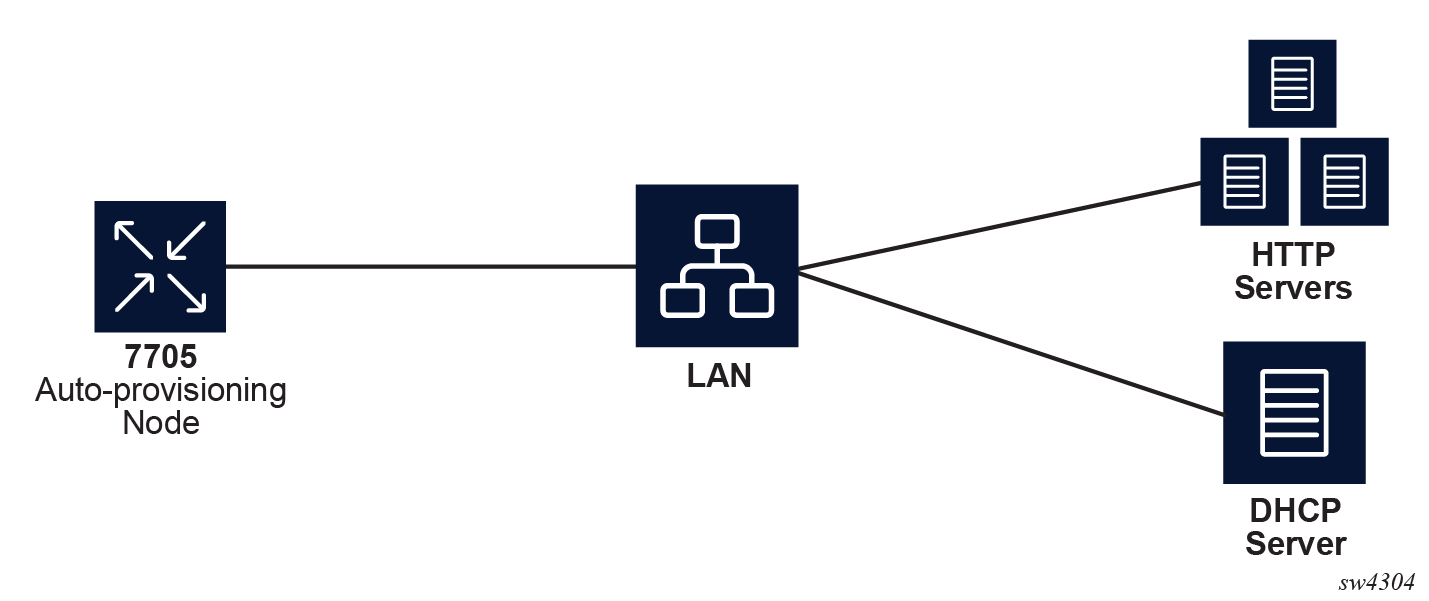
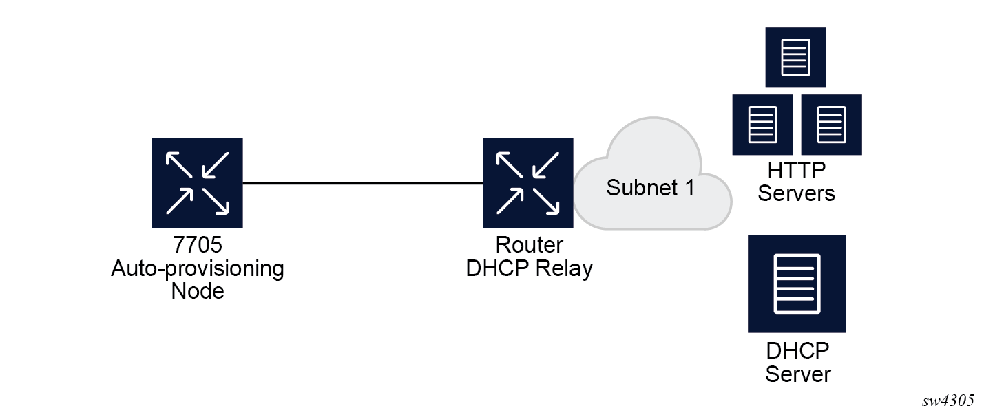
In Example of a network with a DHCP relay, there is a DHCP relay which injects the Option 82 as a gateway address. The DHCP server is assigned the IP address from the pool dictated by the gateway address option 82. The DHCP server and HTTP server are in the same subnet. The DHCP offer has option 3 "router" which is used for a default gateway creation on the 7705 SAR Gen 2.
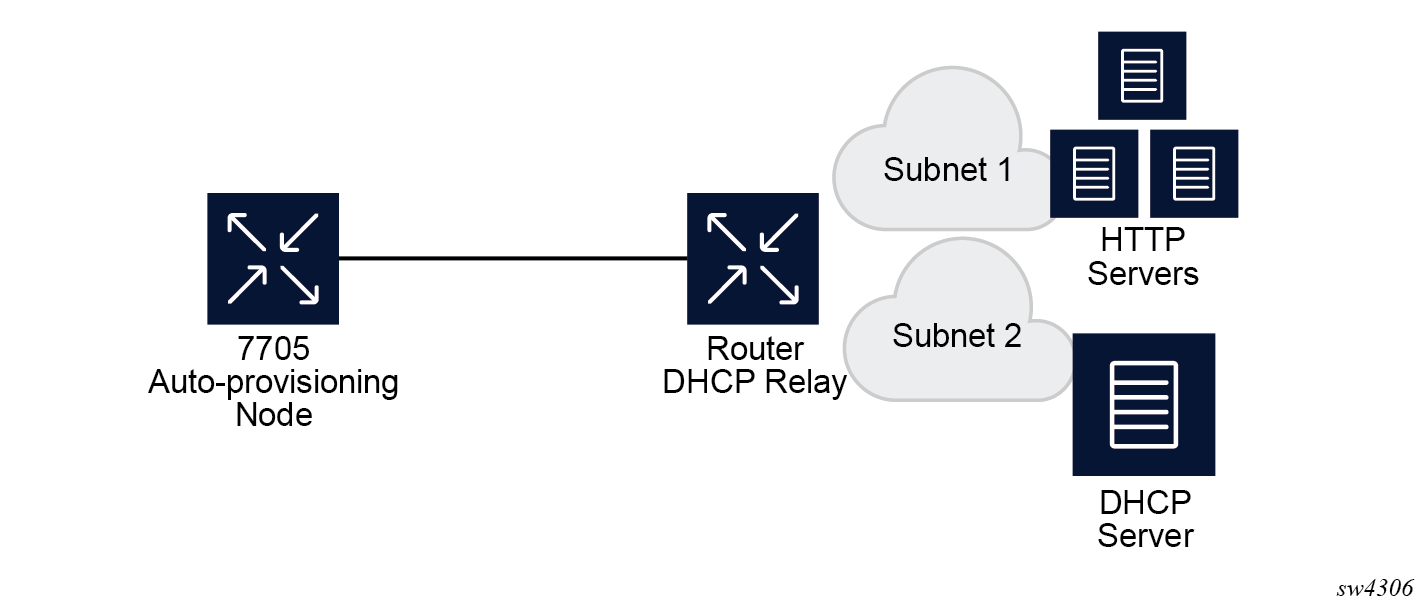
In Example of a network with multiple subnets, all components are in different subnets. The DHCP relay adds Option 82 to the DHCP request as the gateway address which is used for pool selection. The DHCP server must add option 3 configured with the gateway address of the HTTP server.
Auto-provisioning limits
The following are some configuration limits for auto-provisioning:
A maximum of 12 Layer 3 interfaces are supported for auto-provisioning.
Only IPv4 auto-provisioning is supported.
It is highly recommended to only have a basic card, MDA, port, and interface configuration as described in this document and no additional static routes or IGP or BGP protocols when performing auto-provisioning because auto-provisioning installs default static routes that may be affected by any extra routing configuration.
A maximum of 255 characters is supported for the remote URL (200 character maximum for the filepath, the rest for the main URL consisting of the protocol, login credentials, and host IP). A maximum of 200 characters is supported for the local URL. The local file or folder name must not exceed 99 characters.
The maximum number of file pairs for each image/config record is 10.
Auto-provisioning process
In this process, the node detects operational ports, attempts to discover its IP address, and downloads the relevant files for provisioning.
The node sends a DHCP discovery request to the DHCP server using the out-of-band management port. If DHCP discovery is unsuccessful, the node reattempts it using the in-band management ports.
After DHCP discovery is successful, the DHCP server returns an IPv4 or IPv6 FTP or HTTP URL of a file server from which the node can retrieve provisioning information.
The node downloads the provisioning information and performs the auto-provisioning according to the specifications in the files.
After the node is successfully provisioned, it automatically reboots and becomes operationally up.
See Provisioning files for more information about the auto-provisioning process.
The SR OS can also initiate the auto-provisioning process using a tools command.
Auto-provisioning DHCP rules
The following are the DHCP rules in the auto-provisioning stage:
First, auto-provisioning walks through the interfaces with a configured port, where the port is in operational status up, one by one.
It sends a DHCP request to the first configured interface with a port up and no IP address configured.
-
If, on this interface, multiple DHCP offers arrives, only the first offer is sent to the auto-provisioning task and the other offers are ignored. This could occur if the node is on a LAN and multiple DHCP servers are connected to the interface.
-
The DHCP client has an exponential retry mechanism. If the DHCP offer does not arrive from the server, the client resends a DHCP request at 2, 4, 8, 32 and 64 s, with 64 s being the maximum timeout, If the 64 s timeout interval is reached, the DHCP client keeps retrying every 64 s. The user can configure a timeout value. If no DHCP offer has arrived by this timeout value, the auto-provisioning process moves to the next interface.
-
If the DHCP offer arrives on the port and the DHCP client task does not acknowledge the DHCP offer, for any reason, it disables the DHCP client and remove the IP from the port.
-
If the DHCP offer arrives on the port and the DHCP client acknowledges the offer, it sends the information to auto-provisioning. If auto-provisioning does not like the offer, because there is no Option 67, Option 67 is malformed, or for any other reason listed in Auto-provisioning failure, the auto-provisioning process deconfigures the DHCP client and the DHCP client sends a DHCP release, and unassigns the IP address.
-
In case of failure, more information is displayed by the auto-provisioning process and the process moves to the next port that is up and does not have an IP address.
-
If auto-provisioning is successful using the offer and its option, the provisioning file download starts though the protocol dictated by Option 67.
The auto-provisioning command is CLI blocking. All information about the auto-provisioning process is displayed on the CLI and logged.
Auto-provisioning failure
Auto-provisioning fails for the following reasons:
There is no Option 67.
The Option 67 format is not acceptable to auto-provisioning.
The format is a URL or DNS is not supported. There is a failure in the download provisioning file or the server is not reachable.
There is failure in the download of the image or config file using the provisioning file information, for example, the server is not available, the wrong directory is listed, or the wrong credentials are given.
The image or config fails to copy to the compact flash.
The image or config fails to sync to the inactive CPM.
The BOF does not point to the compact flash, for example, it is pointing to the network.
If the auto-provisioning procedure on this interface fails, then auto-provisioning does the following:
Displays information about the blocked CLI and in the log, describing the failure in detail.
Updates the DHCP task so the DHCP task can take the appropriate actions to release the IP address on the interface. This is done by sending a DHCP release for the DHCP ack received from the server.
Goes to the next interface with port up and no IP address.
Note: If no other interface with port up is found, the auto-provisioning task stops and a failure error is displayed on the CLI and in the log.
Administrative tasks
This section contains information to perform administrative tasks.
Saving configurations
Whenever configuration changes are made, the modified configuration must be saved so they are not lost when the system is rebooted.
Configuration files are saved by executing explicit command syntax which includes the file URL location to save the configuration file as well as options to save both default and non-default configuration parameters. Boot option file (BOF) parameters specify where the system should search for configuration and image files as well as other operational parameters during system initialization.
For more information about boot option files, see the Boot Options section.
Specifying post-boot configuration files
Two post-boot configuration extension files are supported and are triggered when either a successful or failed boot configuration file is processed. The boot-bad-exec and boot-good-exec commands specify URLs for the CLI scripts to be run following the completion of the bootup configuration. A URL must be specified or no action is taken.
For example, after a configuration file is successfully loaded, the specified URL can contain a nearly identical configuration file with specific commands enabled or disabled, or particular parameters specified and according to the script which loads that file.
Network timing
In Time Domain Multiplexed (TDM)-based networks (for example, SONET or SDH circuit- switched networks), the concept of network timing is used to prevent over-run or under-run issues where circuits are groomed (rebundled) and switched. Hardware exists in each node that takes a common clock derived from an internal oscillator, a specific receive interface, or special BITS interface and provides it to each synchronous interface in the system. Usually, each synchronous interface is allowed to choose between using the chassis-provided clock or the clocking recovered from the received signal on the interface. The clocking is used to drive the transmit side of the interface. The appropriate configuration at each node which defines how interface clocking is handled must be considered when designing a network that has a centralized timing source so each interface is operating in a synchronous manner.
The effect of timing on a network is dependent on the nature of the type of traffic carried on the network. With bit-wise synchronous traffic (traditional circuit-based voice or video), non-synchronous transmissions cause a loss of information in the streams affecting performance. With packet-based traffic, the applications expect and handle jitter and latency inherent to packet-based networks. When a packet-based network is used to carry voice or video traffic, the applications use data compression and elasticity buffering to compensate for jitter and latency. The network itself relies on appropriate Quality of Service (QoS) definitions and network provisioning to further minimize the jitter and latency the application may experience.
Power supplies
SR OS supports a power-supply command to configure the type and number of power supplies present in the chassis. The operational status of a power source is always displayed by the LEDs on the Control Processor/Switch Fabric Module (CP/SFM) front panel, but the power supply information must be explicitly configured in order for a power supply alarm to be generated if a power source becomes operationally disabled.
System router instances
SR OS supports multiple Layer 3 router instances. These instances have their own IP addressing spaces and configuration options. Router instances are isolated from each other.
The following are the different types of router instances in SR OS:
Base
All SR OS routers have the base router instance: the system created default router instance used to forward user IP traffic among router line card ports. Router interfaces (that is, network interfaces configured under configure router [Base]) and IES services and interfaces exist in the base router instance. The base router instance is identified in SNMP as vRtrType = baseRouter (1) and has a vRtrID of 1.
VPRN instances
Another type of router instance is the set of operator configured VPRN services. Each VPRN service has a unique router instance. For more information about VPRN services and their associated router instances, see the 7705 SAR Gen 2 Layer 3 Services Guide: IES and VPRN. VPRN router instances are identified in SNMP as vRtrType = vprn (2), and the vRtrID is dynamically allocated.
Special system router instances
SR OS routers also support the following special router instances:
management
The management router instance is a system created router instance that is used for management of the router. The management router instance is bound to CPM/CCM ports A/1 and B/1. This is a CPM router instance which cannot be renamed or deleted by an operator. The management router instance is identified in SNMP as vRtrType = vr(3), and the vRtrID is 4095.
vpls-management
The vpls-management router instance is used for management of VPLS services. It is identified in SNMP as vRtrType = vr(3), and the vRtrID is 4094.
User created CPM router instances
User created CPM router instances are user defined router instances that are mainly used with Ethernet ports on the CPM/CCM cards: CPM router instances only use CPM/CCM Ethernet ports as interfaces. CPM router instances have a user-defined name and are the only types of non-VPRN router instances that can be created by the user. User created CPM router instances are identified in SNMP as vRtrType = vr(3), and the vRtrID is dynamically allocated.
Some management protocols can use either the base routing instance (in-band) or the management routing instance (out-of-band). A listing of these protocols can be found in the CPM Filter: Protocols and Ports section of the 7705 SAR Gen 2 System Management Guide. Unless otherwise stated in the detailed description of the protocol, when the server or client for the protocol is reachable via the management routing instance, those protocol messages use the management interface for the protocol communication.
If BOF is set up with autoconfiguration and the DHCP server provides a general default route such as 0.0.0.0/0, with some protocols (like PCEP, TACACS+, RADIUS, and LDAP), Authentication, Authorization, Accounting (AAA) always prefers OOB over in-band connectivity. This is because these protocols prefer to use the OOB management port first. If a matching route is not found, in-band is attempted. The static route provided by DHCP must be properly set to ensure the correct route preference is made by these protocols.
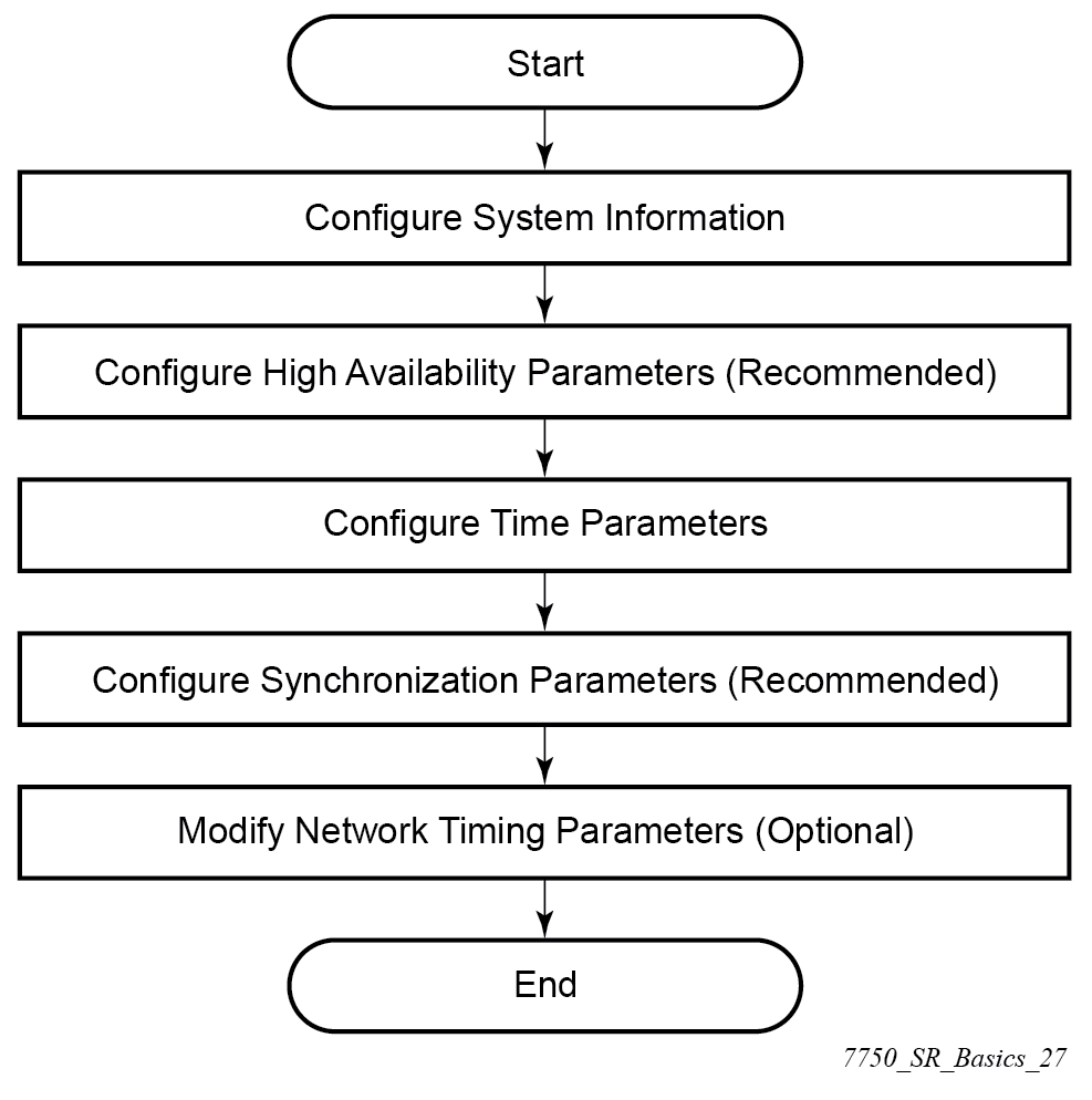
System configuration process overview
The following figure shows the process for basic system provisioning.
Configuration notes
The system must be correctly initialized and the boot loader and BOF successfully executed to access the CLI.
Configuring system management features
This section provides information about configuring system management features.
Saving configurations
Whenever configuration changes are made, the modified configuration must be saved so the changes are not lost when the system is rebooted. The system uses the configuration and image files, as well as other operational parameters necessary for system initialization, according to the locations specified in the boot option file (BOF) parameters. For more information about BOFs, see the System initialization and boot options chapter of this manual:
Configuration files are saved by executing the explicit or implicit commands.
An explicit save writes the configuration to the location specified in the save command (the file URL).
An implicit save writes the configuration to the file specified in the primary configuration location.
If the file-url is not specified in the save command configuration, the system attempts to save the current configuration to the current BOF primary configuration source. If the primary configuration source (path and/or filename) changed since the last boot, the new configuration source is used.
The save command includes an option to save both default and non-default configuration (the detail option).
The index option specifies that the system preserves system indexes when a save command is executed, regardless of the persistent status in the BOF file. During a subsequent boot, the index file is read along with the configuration file. As a result, a number of system indexes are preserved between reboots, including the interface index, LSP IDs, path IDs, and so on. This reduces resynchronizations of the Network Management System (NMS) with the affected network element.
If the save attempt fails at the destination, an error occurs and is logged. The system does not try to save the file to the secondary or tertiary configuration sources unless the path and filename are explicitly named with the save command.
Basic system configuration
This section provides information to configure system parameters and provides configuration examples of common configuration tasks. The minimum system parameters that should be configured are:
-
System time elements
Use the following command to display basic system information such as the system name, platform type, and so on.
show system informationCommon configuration tasks
This section provides an overview of the CLI commands used to configure system parameters:
System information
This section describes the basic system information commands that configure the system name of the router, contact information, location (such as an address, floor, room number, and so on), CLLI code, and global positioning system (GPS) coordinates.
System name
The device's system name is used in the prompt string. Only one system name can be configured; if multiple system names are configured, the last one overwrites the previous entry.
Use the following command to configure the system name.
configure system nameContact
Use the contact command to specify the name of a system administrator, IT staff member, or other administrative entity.
Use the following command to configure the contact.
configure system contactLocation
Use the location command to specify the location of the device. For example, enter the city, building address, floor, room number, and so on, where the router is located.
Use the following command to configure the location.
configure system locationCLLI code
The Common Language Location Code (CLLI code) is an 11-character standardized geographic identifier that is used to uniquely identify the geographic location of a router.
Use the following command to configure the CLLI code.
configure system clli-codeGPS coordinates
Use the optional coordinates command to specify the GPS location of the device. If the string contains special characters (#, $, spaces, and so on), the entire string must be enclosed within double quotes.
Use the following command to configure the coordinates.
configure system coordinatesSystem time elements
The system clock maintains time according to Coordinated Universal Time (UTC). Configure the time zone and summer time (daylight saving time) command options to correctly display time according to the local time zone.
Zone
The zone command sets the time zone and time zone UTC offset for the router. SR OS supports system-defined and user-defined time zones. The system-defined time zones and offsets are listed in System-defined time zones and UTC offsets.
configure system time zoneSummer (daylight saving) time
Configure the start and end dates and offset for summer (daylight saving) time to override system defaults or for user-defined time zones. When configured, the time will be adjusted by changing to the configured offset when summer time starts and returning to the configured offset when summer time ends.
Use commands in the following context to configure the start day, end day, and offset of the summer.
configure system time dst-zoneIf the time zone configured is listed in System-defined time zones and UTC offsets, the start and end command options and offset do not need to be configured with this command unless there is a need to override the system defaults. The command will return an error if the start and end dates and times are not available either in System-defined time zones and UTC offsets or entered as optional command options in this command.
NTP
NTP is the Network Time Protocol defined in RFC 1305, Network Time Protocol (Version 3) Specification, Implementation and Analysis and RFC 5905, Network Time Protocol Version 4: Protocol and Algorithms Specification. It allows for the participating network nodes to keep time more accurately and more importantly they can maintain time in a more synchronized fashion between all participating network nodes.
SR OS uses an NTP process based on a reference build provided by the Network Time Foundation. Nokia strongly recommends that the users review RFC 8633, Network Time Protocol Best Current Practices, when they plan to use NTP with the router. The RFC section ‟Using Enough Time Sources” indicates that using only two time sources (NTP servers) can introduce instability if they provide conflicting information. To maintain accurate time, Nokia recommends configuring three or more NTP servers.
NTP uses stratum levels to define the number of hops from a reference clock. The reference clock is considered to be a stratum-0 device that is assumed to be accurate with little or no delay. Stratum-0 servers cannot be used in a network. However, they can be directly connected to devices that operate as stratum-1 servers. A stratum-1 server is an NTP server with a directly-connected device that provides Coordinated Universal Time (UTC), such as a GPS or atomic clock.
The higher stratum levels are separated from the stratum-1 server over a network path, therefore, a stratum-2 server receives its time over a network link from a stratum-1 server. A stratum-3 server receives its time over a network link from a stratum-2 server.
SR OS routers normally operate as a stratum-2 or higher device. The router relies on an external stratum-1 server to source accurate time into the network. However, SR OS also allows for the use of the local PTP recovered time to be sourced into NTP. In this latter case, the local PTP source appears as a stratum-0 server and SR OS advertises itself as a stratum-1 server. Activation of the PTP source into NTP may impact the network NTP topology because the SR OS router is promoted to stratum-1.
SR OS router runs a single NTP clock which then operates NTP message exchanges with external NTP clocks. Exchanges can be made with external NTP clients, servers, and peers. These exchanges can be through the base, management, or VPRN routing instances.
NTP operates associations between clocks as either client or server, symmetric active and symmetric passive, or broadcast modes. These modes of operation are applied according to which elements are configured on the router. To run server mode, the operator must enable NTP server mode for the base and each needed VPRN routing instance. To run client mode, the operator must configure external servers. If both the local router and remote router are configured with each other as peers, then the router operates in symmetric active mode. If only one side of the association has peering configured, then the modes are symmetric passive. To operate using broadcast mode, interfaces must be configured to transmit as broadcast servers or receive as broadcast clients.
NTP server operation for both unicast and broadcast communication within a VPRN is configured within the VPRN (see "NTP Within a VPRN Service" in the 7705 SAR Gen 2 Layer 3 Services Guide: IES and VPRN).
The following NTP elements are supported:
-
server mode
In this mode, the node advertises the ability to act as a clock source for other network elements. The node, by default, transmits NTP packets in NTP version 4 mode.
-
authentication keys
Authentication keys implement increased security support in carrier and other networks. Both DES and MD5 authentication are supported, as well as multiple keys.
-
operation in symmetric active mode
This capability requires that NTP be synchronized with a specific node that is considered more trustworthy or accurate than other nodes carrying NTP in the system. This mode requires that a specific peer is set.
-
server and peer addressing using IPv6
Both external servers and external peers may be defined using IPv6 or IPv4 addresses. Other features (such as multicast, broadcast) use IPv4 addressing only.
-
broadcast or multicast modes
When operating in these modes, the node receives or sends using either a multicast (default 224.0.1.1) or a broadcast address. Multicast is supported only on the CPM MGMT port.
-
alert when NTP server is not available
When none of the configured servers are reachable on the node, the system reverts to manual timekeeping and issues a critical alarm. When a server becomes available, a trap is issued indicating that standard operation has resumed.
-
NTP and SNTP
If both NTP and SNTP are enabled on the node, then SNTP transitions to an operationally down state. If NTP is removed from the configuration or shut down, then SNTP resumes an operationally up state.
-
gradual clock adjustment
As several applications (such as Service Assurance Agent (SAA)) can use the clock, and if determined that a major (128 ms or more) adjustment needs to be performed, the adjustment is performed by programmatically stepping the clock. If a minor (less than 128 ms) adjustment must be performed, then the adjustment is performed by either speeding up or slowing down the clock.
-
To avoid the generation of too many events/trap the NTP module rates limit the generation of events/traps to three per second. At that point a single trap is generated that indicates that event/trap squashing is taking place.
Authentication-check
NTP supports an authentication mechanism to provide some security and access control to servers and clients. The authentication check feature provides the option to skip the rejection of NTP PDUs that do not match the authentication key or authentication type requirements.
The default behavior when authentication is configured is to reject all NTP PDUs that have a mismatch in either the authentication key ID, type, or key.
When authentication check is configured, NTP PDUs are authenticated on receipt. However, mismatches cause a counter to be increased, one counter for key ID, one for type, and one for key value mismatches.
Use commands in the following context to enable authentication check.
configure system time ntp authentication-checkMD-CLI
[ex:/configure system time ntp]
A:admin@node-2# info
    admin-state enable
    authentication-check true
classic CLI
A:node-2>config>system>time>ntp# info
----------------------------------------------
                authentication-check
                no shutdown
----------------------------------------------
Authentication-key
The authentication-key command configures an authentication key ID, key type, and key used to authenticate NTP PDUs sent to and received from other network elements participating in the NTP. For authentication to work, the authentication key ID, authentication type, and authentication key value must match.
MD-CLI
[ex:/configure system time ntp]
A:admin@node-2# info
    admin-state enable
    authentication-key 1 {
        key "OAwgNUlbzgI hash2"
        type des
    }
classic CLI
A:node-2>config>system>time>ntp# info
----------------------------------------------
                shutdown
                authentication-key 1 key "OAwgNUlbzgI" hash2 type des
----------------------------------------------
Broadcast
The broadcast command is used to transmit broadcast packets on a given interface. Interfaces in the base routing context or the management interface may be specified. Due the relative ease of spoofing of broadcast messages, it is strongly recommended to use authentication with broadcast mode. The messages are transmitted using a destination address that is the NTP Broadcast address. The following example enables NTP and configures the broadcast interface.
MD-CLI
[ex:/configure system time ntp]
A:admin@node-2# info
    admin-state enable
    broadcast "Base" interface-name "int11" {
        version 4
        ttl 127
    }
classic CLI
A:node-2>config>system>time>ntp# info
----------------------------------------------
                broadcast interface int11 version 4 ttl 127
                no shutdown
----------------------------------------------
Broadcastclient
The broadcastclient command enables listening to NTP broadcast messages on the specified interface. Interfaces in the base routing context or the management interface may be specified. Due the relative ease of spoofing of broadcast messages, it is strongly recommended to use authentication with broadcast mode. The messages must have a destination address of the NTP Broadcast address. The following example enables NTP and configures the broadcast client.
MD-CLI
[ex:/configure system time ntp]
A:admin@node-2# info
    admin-state enable
    broadcast-client "Base" interface-name "int11" {
    }
classic CLI
A:node-2>config>system>time>ntp# info
----------------------------------------------
                broadcastclient interface int11
                no shutdown
----------------------------------------------
Multicast
When configuring NTP the node can be configured to transmit or receive multicast packets on the CPM MGMT port. Broadcast and multicast messages can easily be spoofed; therefore, authentication is strongly recommended. Multicast is used to configure the transmission of NTP multicast messages. When transmitting multicast NTP messages the default address of 224.0.1.1 is used. The following example enables NTP and multicast.
MD-CLI
[ex:/configure system time ntp]
A:admin@node-2# info
    admin-state enable
    multicast {
    }
classic CLI
A:node-2>config>system>time>ntp# info
----------------------------------------------
                multicast
                no shutdown
----------------------------------------------
Multicastclient
The multicastclient command is used to configure an address to receive multicast NTP messages on the CPM MGMT port. Broadcast and multicast messages can easily be spoofed, therefore, authentication is strongly recommended. If multicastclient is not configured, all NTP multicast traffic is ignored. The following example enables NTP and configures the address to receive multicast NTP messages.
MD-CLI
[ex:/configure system time ntp]
A:admin@node-2# info
    admin-state enable
    multicast-client {
        authenticate true
    }
classic CLI
A:node-2>config>system>time>ntp# info
----------------------------------------------
                multicastclient
                no shutdown
----------------------------------------------
NTP-server
The ntp-server command configures the node to assume the role of an NTP server. Unless the server command is used, this node will function as an NTP client only and will not distribute the time to downstream network elements. If the authenticate command option is specified, the NTP server requires client packets to be authenticated.
The following is an example of a configuration output of NTP enabled with the ntp-server command configured.
MD-CLI
[ex:/configure system time ntp]
A:admin@node-2# info
    admin-state enable
    ntp-server {
        authenticate true
    }
classic CLI
A:node-2>config>system>time>ntp# info
----------------------------------------------
        no shutdown
        ntp-server
----------------------------------------------
Peer
Configuration of an NTP peer configures symmetric active mode for the configured peer. Although any system can be configured to peer with any other NTP node, Nokia recommends configuring authentication and to configure known time servers as their peers. Administratively disable this command to remove the configured peer.
Use commands in the following context to configure symmetric active mode.
configure system time ntp peerMD-CLI
[ex:/configure system time ntp]
A:admin@node-2# info
    admin-state enable
    peer 192.168.1.1 router-instance "Base" {
        key-id 1
    }
classic CLI
A:node-2>config>system>time>ntp# info
----------------------------------------------
            no shutdown
            peer 192.168.1.1 key-id 1
----------------------------------------------
Server
The server command is used when the node should operate in client mode with the NTP server specified in the address field. Up to ten NTP servers can be configured. The following example enables NTP and configures the server.
MD-CLI
[ex:/configure system time ntp]
A:admin@node-2# info
    admin-state enable
    server 192.168.1.1 router-instance "Base" {
        key-id 1
    }
classic CLI
A:node-2>config>system>time>ntp# info
----------------------------------------------
                no shutdown
                server 192.168.1.1 key 1
----------------------------------------------
SNTP
SNTP is a compact, client-only version of NTP. SNTP can only receive the time from SNTP/NTP servers; it cannot be used to provide time services to other systems. SNTP can be configured in either broadcast or unicast client mode.
SNTP time elements include the Broadcast-client and Server-address.
Use the commands in the following context to configure the SNTP.
configure system time sntpBroadcast-client
- MD-CLI
configure system time sntp sntp-state broadcast - classic
CLI
configure system time sntp broadcast-client
The following example shows SNTP enabled with the broadcast client.
MD-CLI
[ex:/configure system time sntp]
A:admin@node-2# info
    admin-state enable
    sntp-state broadcast
classic CLI
A:node-2>config>system>time>sntp# info
----------------------------------------------
                broadcast-client
                no shutdown
----------------------------------------------
Server-address
- MD-CLI
configure system time sntp server - classic
CLI
configure system time sntp server-address
The following is an example of a configuration output of SNTP enabled with the server-address command configured.
MD-CLI
[ex:/configure system time sntp]
A:admin@node-2# info
    admin-state enable
    server 10.10.0.94 {
        version 1
        prefer true
        interval 100
    }
classic CLI
A:node-2>config>system>time>sntp# info
----------------------------------------------
                server-address 10.10.0.94 version 1 preferred interval 100
                no shutdown
----------------------------------------------
CRON
The CRON feature supports periodic and date and time-based scheduling in SR OS. CRON can be used, for example, to schedule Service Assurance Agent (SAA) functions. CRON functionality includes the ability to specify scripts that need to be run, when they are scheduled, including one-time only functionality (one-shot), interval and calendar functions. Scheduled reboots, peer turn ups, service assurance agent tests and more can all be scheduled with CRON, as well as OAM events, such as connectivity checks, or troubleshooting runs.
CRON supports the schedule element. The schedule function configures the type of schedule to run, including one-time only (one-shot), periodic, or calendar-based runs. All runs are determined by month, day of month or weekday, hour, minute, and interval (seconds).
Schedule
The schedule command configures the type of schedule to run, including one-time only (oneshot), periodic, or calendar-based runs. All runs are determined by month, day of the month or weekday, hour, minute, and interval (seconds). If the end-time and interval command options are both configured, whichever condition is reached first is applied.
The following is an example of a configuration output that schedules a script named ‟test” to run every 15 minutes on the 17th of each month and every Friday until noon on July 17, 2007.
MD-CLI
[ex:/configure system cron]
A:admin@node-2# info
    schedule "test" owner "TiMOS CLI" {
        day-of-month [17]
        minute [0 15 30 45]
        weekday [friday]
        end-time {
            date-and-time 2007-07-17T12:00:00.0+00:00
        }
    }
classic CLI
*A:node-2>config>system>cron# info
----------------------------------------------
        schedule "test"
            shutdown
            day-of-month 17
            minute 0 15 30 45
            weekday friday
            end-time 2007/07/17 12:00
        exit
----------------------------------------------
ANCP enhancements
Persistency is available for subscriber ANCP attributes and is stored on the on-board compact flash card. ANCP data stays persistent during an ISSU as well as node reboots. During recovery, ANCP attributes are first restored fully from the persistence file, and incoming ANCP sessions are temporarily on hold. Afterwards, new ANCP data can overwrite any existing values. This new data is then stored into the compact flash in preparation for the next event.
Configuring backup copies
The config-backup command allows you to specify the maximum number of backup versions of configuration and index files kept in the primary location.
For example, assume the maximum number of backup versions is set to 5 and the configuration file is called xyz.cfg. When the configuration is saved, the file xyz.cfg is saved with a .1 extension. Each subsequent config-backup command increments the numeric extension until the maximum count is reached. The oldest file (5) is deleted as more recent files are saved.
xyz.cfg
xyz.cfg.1
xyz.cfg.2
xyz.cfg.3
xyz.cfg.4
xyz.cfg.5
xyz.ndx
Each persistent index file is updated at the same time as the associated configuration file. When the index file is updated, the save is performed to xyz.cfg and the index file is created as xyz.ndx. Synchronization between the active and standby SF/CPMSF/CPM is performed for all configurations and their associated persistent index files.
Use the following commands to specify the maximum number of backup versions of the configuration and index files kept in the primary location:
- MD-CLI
configure system management-interface configuration-save configuration-backups - classic
CLI
configure system config-backup
Configuring power supply
The 7705 SAR-1 supports component redundancy for the power supply feeds. The use of up to two power supply feeds for 1+1 power redundancy is supported. A power feed can fail without impacting traffic when a redundant power feed configuration is in use.
The following output shows the chassis power supply information for the 7705 SAR-1.
A:node-2 show chassis power-supply
===============================================================================
Chassis 1 Detail
===============================================================================
Power Supply Information
  Number of power supplies          : 2

  Power supply number               : 1
    Power supply type               : none
    Status                          : failed

  Power supply number               : 2
    Power supply type               : none
    Status                          : failed
===============================================================================
Configuring multichassis redundancy for LAG
When configuring the associated LAG ID, the LAG must be in access mode and LACP must be enabled. The following example configures multichassis redundancy features.
MD-CLI
[ex:/configure redundancy multi-chassis]
A:admin@node-2# info
    peer 10.10.10.2 {
        admin-state enable
        description "Mc-Lag peer 10.10.10.2"
        mc-lag {
            admin-state enable
            lag "lag-1" {
                lacp-key 32666
                system-id 00:00:00:33:33:33
                system-priority 32888
            }
        }
    }
classic CLI
A:node-2>config>redundancy>multi-chassis# info
---------------------------------------------
        peer 10.10.10.2 create
            description "Mc-Lag peer 10.10.10.2"
            mc-lag
                no shutdown
            exit
            no shutdown
        exit
---------------------------------------------
Post-boot configuration extension files
Two post-boot configuration extension files are supported and are triggered when either a successful or failed boot configuration file is processed. The commands specify URLs for the CLI scripts to be run following the completion of the startup configuration. A URL must be specified or no action is taken. The commands are persistent between router reboots and are included in the configuration saves.
Use the following commands to specify the CLI scripts that are run following the completion of the boot-up configuration.
configure system boot-bad-exec
configure system boot-good-exec
Show command output and console messages
Use the following command to show the current value of the bad and good exec URLs and indicate whether a post-boot configuration extension file was executed when the system was booted.
show system informationIf an extension file was executed, the command also indicates whether it completed successfully.
The following example shows the show output for the 7705 SAR-1.
Show system information output for the 7705 SAR-1
===============================================================================
System Information
===============================================================================
System Name            : node-2
System Type            : 7705 SAR-1
...
BOF Source             : cf3:
Image Source           : primary
Config Source          : N/A
Last Booted Config File: N/A
Last Boot Cfg Version  : N/A
Last Boot Config Header: N/A
Last Boot Index Version: N/A
Last Boot Index Header : N/A
Last Saved Config      : ftp://test:test@192.168.xx.xxx/./images/dut-bg.cfg
Time Last Saved        : 2025/03/27 20:12:15
Changes Since Last Save: No
User Last Modified     : admin
Max Cfg/BOF Backup Rev : 5
Cfg-OK Script          : ftp://test:test@192.168.xx.xxx/./images/env.cfg
Cfg-OK Script Status   : success
Cfg-Fail Script        : N/A
Cfg-Fail Script Status : not used
...
===============================================================================
When executing a post-boot configuration extension file, status messages are displayed on the console before the ‟Login” prompt.
The following example shows a failed bootup configuration that caused a boot-bad-exec file containing another error to be executed.
Failed start-up configuration error message
Attempting to exec configuration file:
’ftp://test:test@192.168.xx.xxx/./12.cfg’ ...
System Configuration
Log Configuration
MAJOR: CLI #1009 An error occurred while processing a CLI command -
File ftp://test:test@192.168.xx.xxx/./12.cfg, Line 195: Command "log" failed.
CRITICAL: CLI #1002 An error occurred while processing the configuration file.
The system configuration is missing or incomplete.
MAJOR: CLI #1008 The SNMP daemon is disabled.
If desired, enable SNMP with the ’config>system>snmp no shutdown’ command.
Attempting to exec configuration failure extension file:
’ftp://test:test@192.168.xx.xxx/./fail.cfg’ ...
Config fail extension
Enabling SNMP daemon
MAJOR: CLI #1009 An error occurred while processing a CLI command -
File ftp://test:test@192.168.xx.xxx/./fail.cfg, Line 5: Command "abc log" failed.
TiMOS-B-x.0.Rx both/hops ALCATEL Copyright (c) 2000-20011 Alcatel-Lucent.
All rights reserved. All use subject to applicable license agreements.
Built on Thu Nov 207 19:19:11 PST 2008 by builder in /rel5x.0/b1/Rx/panos/main


Login:
Configuring system monitoring thresholds
This section provides information about configuring system monitoring thresholds.
Creating events
The event command controls the generation and notification of threshold crossing events configured with the alarm command. When a threshold crossing event is triggered, the rmon event configuration optionally specifies whether an entry in the RMON-MIB log table is created to record the occurrence of the event. It can also specify whether an SNMP notification (trap) be generated for the event. There are two notifications for threshold crossing events: a rising alarm and a falling alarm.
Creating an event entry in the RMON-MIB log table does not create a corresponding entry in the event logs. However, when the event is set to trap, the generation of a rising alarm or falling alarm notification creates an entry in the event logs and that is distributed to whatever log destinations are configured: console, session, memory, file, syslog, or SNMP trap destination. The logger message includes a rising or falling threshold crossing event indicator, the sample type (absolute or delta), the sampled value, the threshold value, the RMON alarm ID, the associated RMON event ID, and the sampled SNMP object identifier.
The alarm command configures an entry in the RMON-MIB alarm table. The alarm command controls the monitoring and triggering of threshold crossing events. For notification or logging of a threshold crossing event to occur, there must be at least one associated rmon event configured.
The agent periodically takes statistical sample values from the MIB variable specified for monitoring and compares them to thresholds that have been configured with the alarm command. The alarm command configures the MIB variable to be monitored, the polling period (interval), sampling type (absolute or delta value), and rising and falling threshold parameters. If a sample has crossed a threshold value, the associated event is generated.
Preconfigured CLI threshold commands are available. Preconfigured commands hide some of the complexities of configuring RMON alarm and event commands and perform the same function. The preconfigured commands do not require the user to know the SNMP object identifier to be sampled. The preconfigured threshold configurations include memory warnings and alarms and compact flash usage warnings and alarms.
MD-CLI
[ex:/configure system thresholds]
A:admin@node-2# info
    cflash-cap-warn-percent "cf1-B:" {
        rising-threshold 100
        falling-threshold 50
        interval 240
        startup-alarm either
    }
    kb-memory-use-alarm {
        rising-threshold 50000000
        falling-threshold 45999999
        interval 500
        startup-alarm either
    }
    rmon {
        event 5 {
            description "alarm testing"
            owner "Timos CLI"
        }
    }
classic CLI
A:node-2>config>system>thresholds# info
----------------------------------------------
            rmon
                event 5 description "alarm testing" owner "Timos CLI"
            exit
            cflash-cap-warn cf1-B: rising-threshold 2000000 falling-threshold
1999900 interval 240 trap
            memory-use-alarm rising-threshold 50000000 falling-threshold
45999999 interval 500
----------------------------------------------
Configuring LLDP
Use the commands in the following context to configure LLDP.
configure system lldpLLDP default configuration (MD-CLI)
[ex:/configure system lldp]
A:admin@node-2# info detail
 ## apply-groups
 ## apply-groups-exclude
    admin-state enable
    tx-credit-max 5
    message-fast-tx 1
    message-fast-tx-init 4
    tx-interval 30
    tx-hold-multiplier 4
    reinit-delay 2
    notification-interval 5
LLDP default configuration (classic CLI)
A:node-2>config>system>lldp# info detail
----------------------------------------------
             no tx-interval
             no tx-hold-multiplier
             no reinit-delay
             no notification-interval
             no tx-credit-max
             no message-fast-tx
             no message-fast-tx-init
             no shutdown
----------------------------------------------
LLDP port configuration (MD-CLI)
[ex:/configure port 1/1/1 ethernet lldp]
A:admin@node-2# info
    dest-mac nearest-bridge {
        receive true
        transmit true
        tx-tlvs {
            port-desc true
            sys-cap true
        }
        tx-mgmt-address system {
            admin-state enable
        }
    }
LLDP port configuration (classic CLI)
A:node-2>config>port>ethernet>lldp# info
----------------------------------------------
       dest-mac nearest-bridge
              admin-status tx-rx
              tx-tlvs port-desc sys-cap
              tx-mgmt-address system
       exit
----------------------------------------------
Global system LLDP configuration (MD-CLI)
[ex:/configure system lldp]
A:admin@node-2# info
    tx-interval 10
    tx-hold-multiplier 2
    reinit-delay 5
    notification-interval 10
Global system LLDP configuration (classic CLI)
A:node-2>config>system>lldp# info
----------------------------------------------
        tx-interval 10
        tx-hold-multiplier 2
        reinit-delay 5
        notification-interval 10
----------------------------------------------