Ethernet Virtual Private Networks
This chapter provides information about Ethernet Virtual Private Networks (EVPN).
Overview of EVPN applications
EVPN is an IETF technology as defined in RFC 7432, BGP MPLS-Based Ethernet VPN, that uses a specific BGP address family and allows VPLS services to be operated as IP-VPNs, where the MAC addresses and the information to set up the flooding trees are distributed by BGP.
EVPN is defined to fill the gaps of other L2VPN technologies such as VPLS. The main objective of the EVPN is to build E-LAN services in a similar way to RFC 4364 IP-VPNs, while supporting MAC learning within the control plane (distributed by MP-BGP), efficient multidestination traffic delivery, and active/active multihoming.
EVPN can be used as the control plane for different data plane encapsulations. The Nokia implementation supports the following data planes:
-
EVPN for VXLAN overlay tunnels (EVPN-VXLAN)
EVPN for VXLAN overlay tunnels (EVPN-VXLAN), being the Data Center Gateway (DGW) function, is the main application for this feature. In this application, VXLAN is expected within the Data Center and VPLS SDP bindings or SAPs are expected for WAN connectivity. R-VPLS and VPRN connectivity to the WAN is also supported.
The EVPN-VXLAN functionality is standardized in RFC 8365.
-
EVPN for MPLS tunnels (EVPN-MPLS)
EVPN-MPLS is supported where PEs are connected by any type of MPLS tunnel. EVPN-MPLS is generally used as an evolution for VPLS services in the WAN, and Data Center Interconnect is one of the main applications.
The EVPN-MPLS functionality is standardized in RFC 7432.
-
EVPN for PBB over MPLS tunnels (PBB-EVPN)
PEs are connected by PBB over MPLS tunnels in this data plane. It is usually used for large scale E-LAN and E-Line services in the WAN.
The PBB-EVPN functionality is standardized in RFC 7623.
The 7705 SAR Gen 2 EVPN VXLAN implementation is integrated in the Nuage Data Center architecture, where the router serves as the DGW.
For more information about the Nuage Networks architecture and products, see the Nuage Networks Virtualized Service Platform Guide. The following sections describe the applications supported by EVPN.
EVPN for VXLAN tunnels in a Layer 2 DGW (EVPN-VXLAN)
The following figure shows the use of EVPN for VXLAN overlay tunnels when it is used as a Layer 2 DGW.
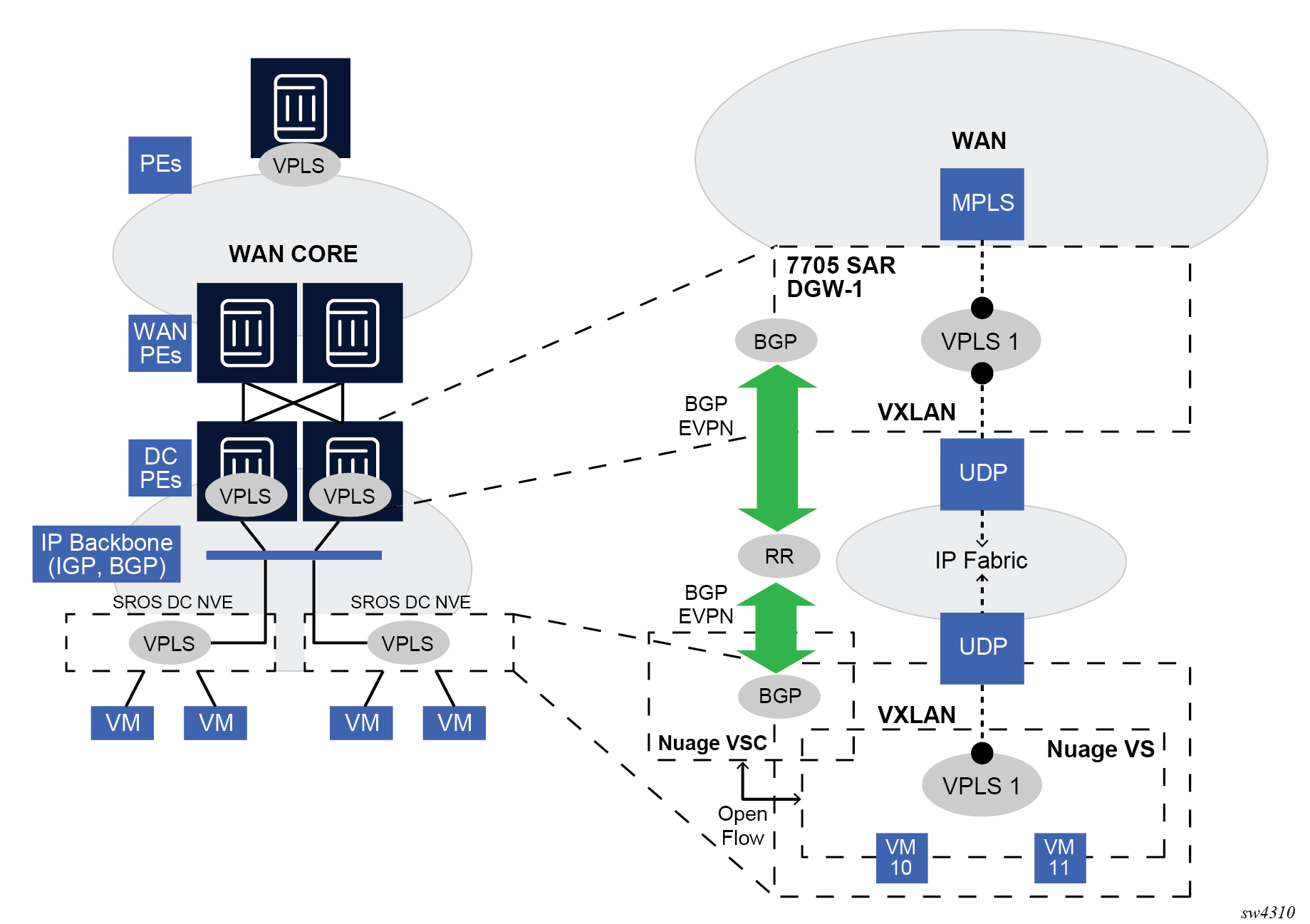
Data Center (DC) providers require a DGW solution that can extend tenant subnets to the WAN. Customers can deploy the NVO3-based solutions in the DC, where EVPN is the standard control plane and VXLAN is a predominant data plane encapsulation. The Nokia DC architecture uses EVPN and VXLAN as the control and data plane solutions for Layer 2 connectivity within the DC and so does the SR OS.
While EVPN VXLAN is used within the DC, some service providers use VPLS and H-VPLS as the solution to extend Layer 2 VPN connectivity. Layer 2 DC PE with VPLS to the WAN shows the Layer 2 DGW function on the 7705 SAR Gen 2 routers, providing VXLAN connectivity to the DC and regular VPLS connectivity to the WAN.
The WAN connectivity is based on VPLS where SAPs (null, dot1q, and qinq), spoke SDPs (FEC type 128 and 129), and mesh-SDPs are supported.
The DC GWs can provide multihoming resiliency through the use of BGP multihoming.
EVPN-MPLS can also be used in the WAN. In this case, the Layer 2 DGW function provides translation between EVPN-VXLAN and EVPN-MPLS. EVPN multihoming can be used to provide DGW redundancy.
If point-to-point services are needed in the DC, SR OS supports the use of EVPN-VPWS for VXLAN tunnels, including multihoming, in accordance with RFC 8214.
EVPN for VXLAN tunnels in a Layer 2 DC with integrated routing bridging connectivity on the DGW
Gateway IRB on the DC PE for an L2 EVPN/VXLAN DC shows the use of EVPN for VXLAN overlay tunnels when the DC provides Layer 2 connectivity and the DGW can route the traffic to the WAN through an R-VPLS and linked VPRN.
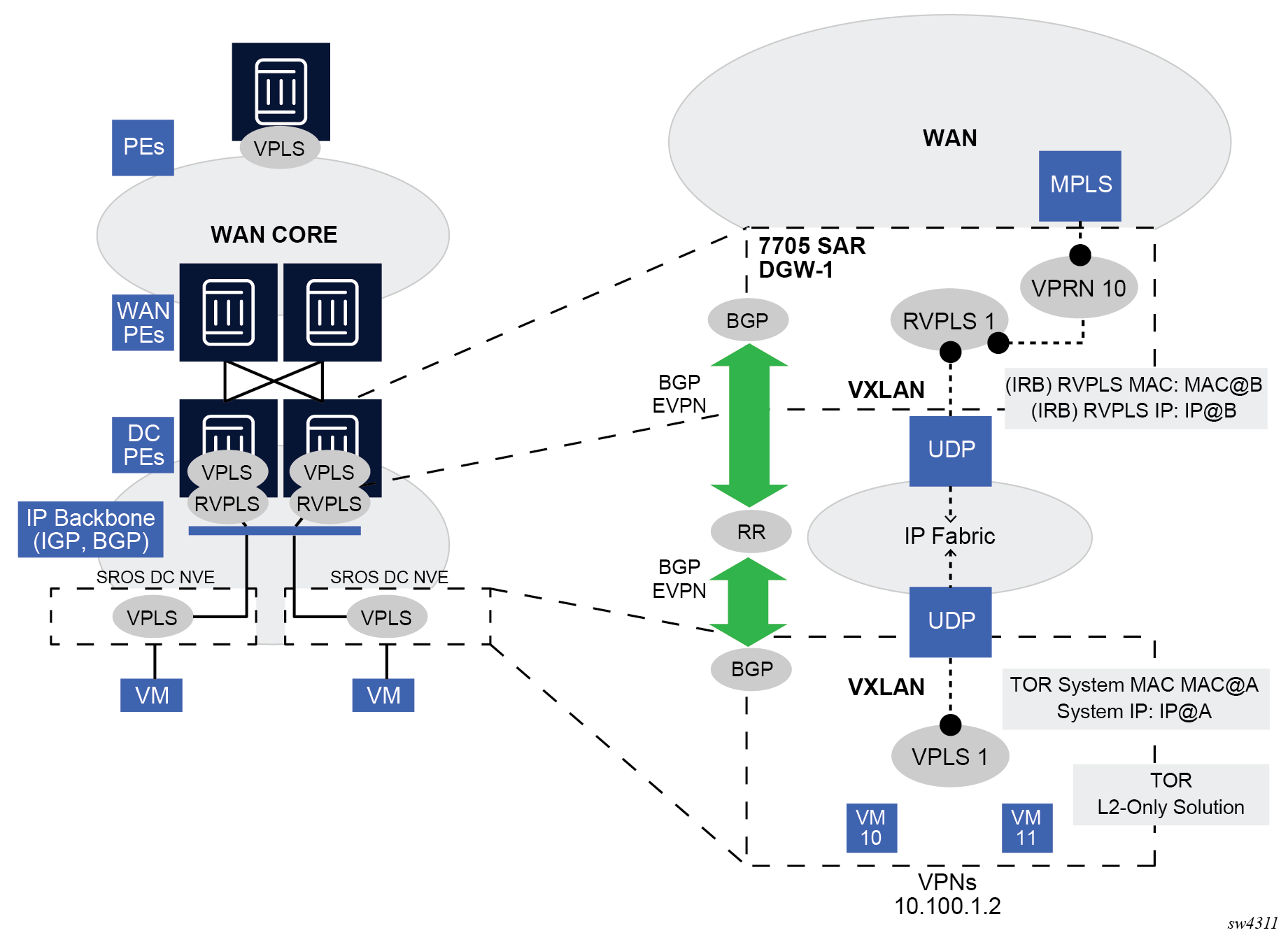
In some cases, the DGW must provide a Layer 3 default gateway function to all the hosts in a specified tenant subnet. In this case, the VXLAN data plane is terminated in an R-VPLS on the DGW, and connectivity to the WAN is accomplished through regular VPRN connectivity. The 7705 SAR Gen 2 supports IPv4 and IPv6 interfaces as default gateways in this scenario.
EVPN for VXLAN tunnels in a Layer 3 DC with integrated routing bridging connectivity among VPRNs
The following figure shows the use of EVPN for VXLAN tunnels when the DC provides distributed Layer 3 connectivity to the DC tenants.
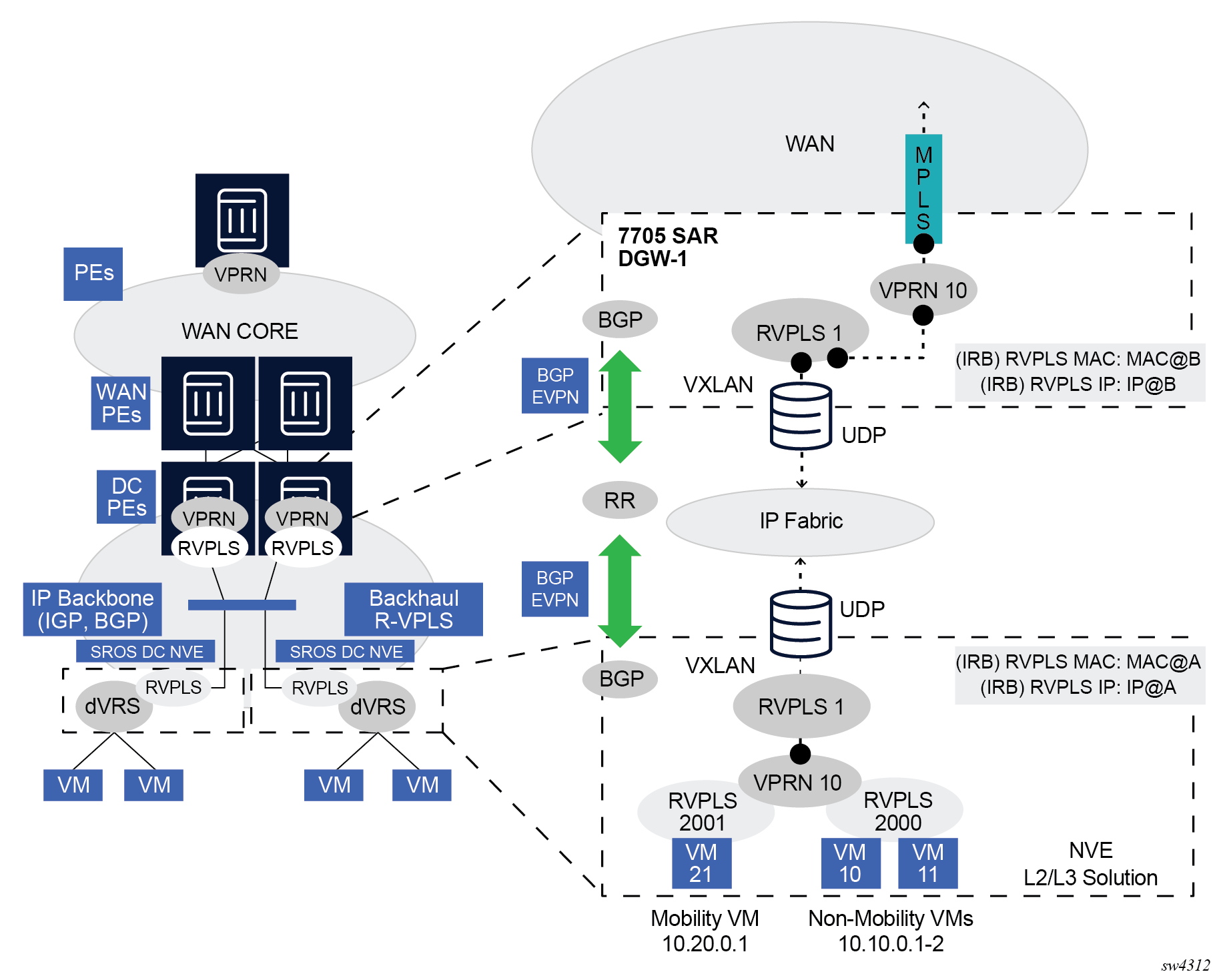
Each tenant has several subnets for which each DC Network Virtualization Edge (NVE) provides intra-subnet forwarding. An NVE may be a Nokia VSG (Virtual Switch Gateway), VSC (Virtual Switch Controller)/VRS (Virtual Routing and Switching), or any other NVE in the market supporting the same constructs, and each subnet typically corresponds to an R-VPLS. For example, in the preceding figure, subnet 10.20.0.0 corresponds to R-VPLS 2001 and subnet 10.10.0.0 corresponds to R-VPLS 2000.
In this example, the NVE also provides inter-subnet forwarding by connecting all the local subnets to a VPRN instance. When the tenant requires Layer 3 connectivity to the IP-VPN in the WAN, a VPRN is defined in the DC GWs, which connects the tenant to the WAN. That VPRN instance is connected to the VPRNs in the NVEs by means of an Integrated Routing and Bridging (IRB) backhaul R-VPLS. This IRB backhaul R-VPLS provides a scalable solution because it allows Layer 3 connectivity to the WAN without the need for defining all of the subnets in the DC gateway.
The 7705 SAR Gen 2 DGW supports the IRB backhaul R-VPLS model, where the R-VPLS runs EVPN-VXLAN and the VPRN instances exchange IP prefixes (IPv4 and IPv6) through the use of EVPN. Interoperability between the EVPN and IP-VPN for IP prefixes is also fully supported.
EVPN for VXLAN tunnels in a Layer 3 DC with EVPN-tunnel connectivity among VPRNs
The following figure shows the use of EVPN for VXLAN tunnels when the DC provides distributed Layer 3 connectivity to the DC tenants and the VPRN instances are connected through EVPN tunnels.
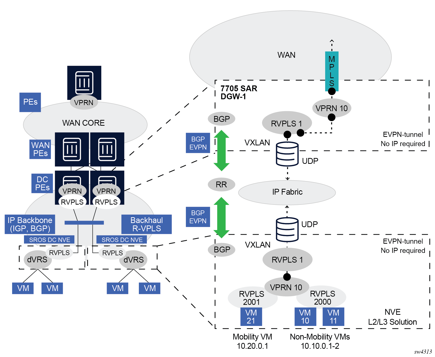
The solution described in section EVPN for VXLAN tunnels in a Layer 3 DC with integrated routing bridging connectivity among VPRNs provides a scalable IRB backhaul R-VPLS service where IRB interfaces can be used to connect all the VPRN instances for a specified tenant. When this IRB backhaul R-VPLS is exclusively used as a backhaul and does not have any SAPs or SDP-bindings directly attached, the solution can be optimized by using EVPN tunnels.
EVPN tunnels are enabled using the evpn-tunnel command under the R-VPLS interface configured on the VPRN. EVPN tunnels provide the following benefits to EVPN-VXLAN IRB backhaul R-VPLS services:
-
easier provisioning of the tenant service
If an EVPN tunnel is configured in an IRB backhaul R-VPLS, there is no need to provision the IRB IPv4 addresses on the VPRN. Provisioning is easier to automate and saves IP addresses from the tenant space.
Note: IPv6 interfaces do not require the provisioning of an IPv6 Global Address; a Link Local Address is automatically assigned to the IRB interface. -
higher scalability of the IRB backhaul R-VPLS
If EVPN tunnels are enabled, multicast traffic is suppressed in the EVPN-VXLAN IRB backhaul R-VPLS service (it is not required). As a result, the number of VXLAN binds in IRB backhaul R-VPLS services with EVPN-tunnels can be much higher.
This optimization is fully supported by the 7705 SAR Gen 2.
EVPN for MPLS tunnels in E-LAN services
The following figure shows the use of EVPN for MPLS tunnels. In this case, EVPN is used as the control plane for E-LAN services in the WAN.
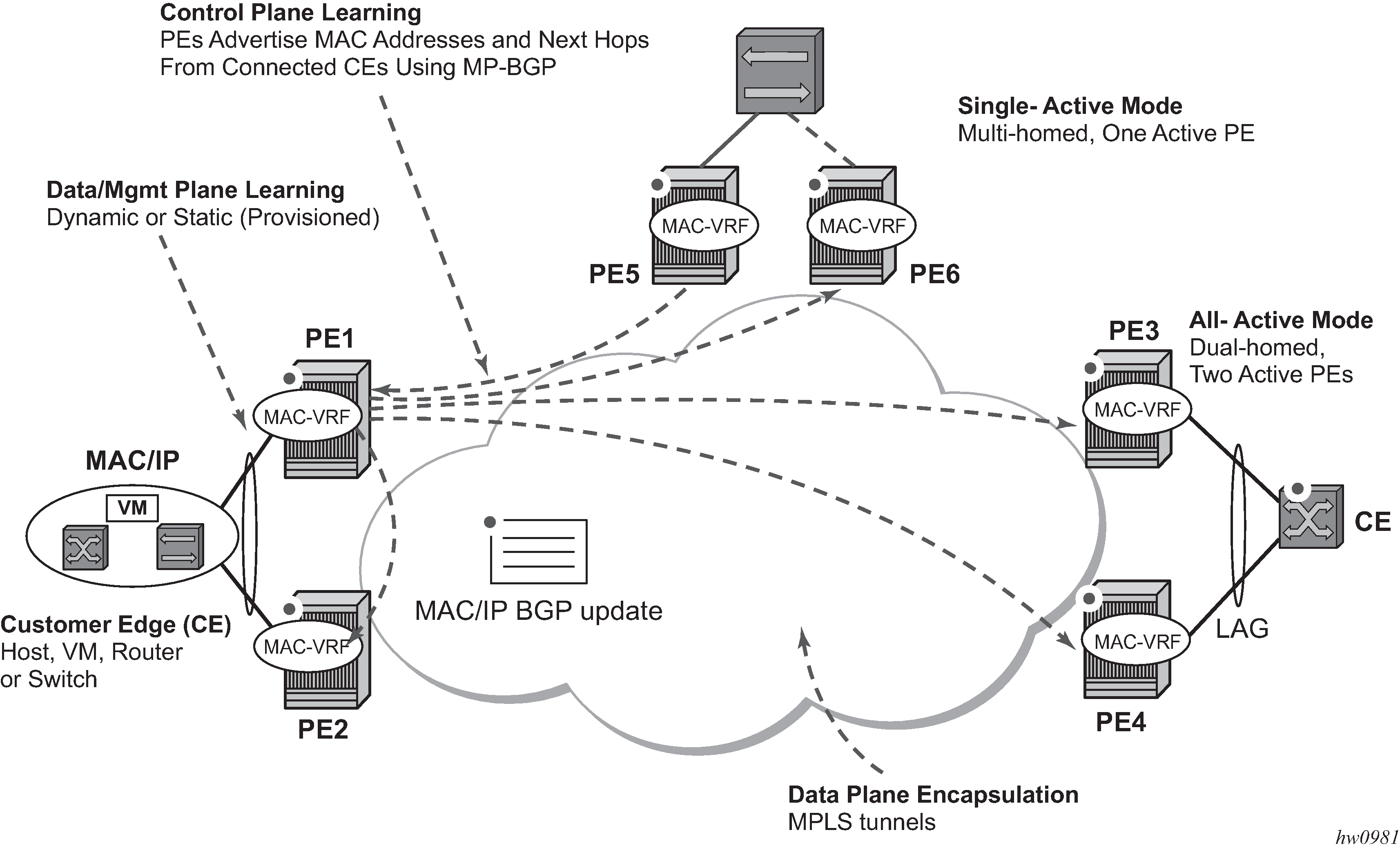
As defined in RFC 7432, EVPN-MPLS an L2VPN technology that can fill the gaps in VPLS for E-LAN services. Service providers that offer E-LAN services request EVPN for its multihoming capabilities and to leverage the optimization EVPN provides.
EVPN supports both all-active multihoming (per flow load-balancing multihoming) as well as single-active multihoming (per-service load-balancing multihoming). Although VPLS already supports single-active multihoming, EVPN single-active multihoming is deemed the superior technology because of its mass-withdrawal capabilities to speed up convergence in scaled environments.
EVPN technology provides significant benefits, including:
superior multihoming capabilities
IP-VPN-like operation and control for E-LAN services
reduction and (in some cases) suppression of the broadcast, unknown unicast, and multicast (BUM) traffic in the network
simple provision and management
new set of tools to control the distribution of MAC addresses and ARP entries in the network
The SR OS EVPN-MPLS implementation is compliant with RFC 7432.
EVPN-MPLS can also be enabled in R-VPLS services with the same feature-set that is described for VXLAN tunnels in sections and EVPN for VXLAN tunnels in a Layer 3 DC with integrated routing bridging connectivity among VPRNs and EVPN for VXLAN tunnels in a Layer 3 DC with EVPN-tunnel connectivity among VPRNs.
EVPN for MPLS tunnels in E-Line services
The MPLS network can be shared between EVPN for E-LAN and E-Line services using EVPN in the control plane. EVPN for E-Line services (EVPN-VPWS) is a simplification of the RFC 7432 procedures, and it is supported in compliance with RFC 8214.
EVPN for MPLS tunnels in E-Tree services
The MPLS network used by E-LAN and E-Line services can also be shared by Ethernet-Tree (E-Tree) services using the EVPN control plane. EVPN E-Tree services use the EVPN control plane extensions described in IETF RFC 8317 and are supported on the 7705 SAR Gen 2.
EVPN for VXLAN tunnels and cloud technologies
This section provides information about EVPN for VXLAN tunnels and cloud technologies.
VXLAN
The SR OS, SR Linux and Nuage solution for DC supports VXLAN (Virtual eXtensible Local Area Network) overlay tunnels as per RFC 7348.
VXLAN addresses the data plane needs for overlay networks within virtualized DCs accommodating multiple tenants. The main attributes of the VXLAN encapsulation are the following:
-
VXLAN is an overlay network encapsulation used to carry MAC traffic between VMs over a logical Layer 3 tunnel.
-
VXLAN encapsulation avoids the Layer 2 MAC explosion, because VM MACs are only learned at the edge of the network. Core nodes simply route the traffic based on the destination IP (which is the system IP address of the remote PE or VTEP-VXLAN Tunnel End Point).
-
It supports multipath scalability through ECMP (to a remote VTEP address, based on source UDP port entropy) while preserving the Layer 2 connectivity between VMs. xSTP is no longer needed in the network.
-
It supports multiple tenants, each with their own isolated Layer 2 domain. The tenant identifier is encoded in the VNI field (VXLAN Network Identifier) and allows up to 16M values, as opposed to the 4k values provided by the 802.1q VLAN space.
The following figure shows an example of the VXLAN encapsulation supported by the Nokia implementation.
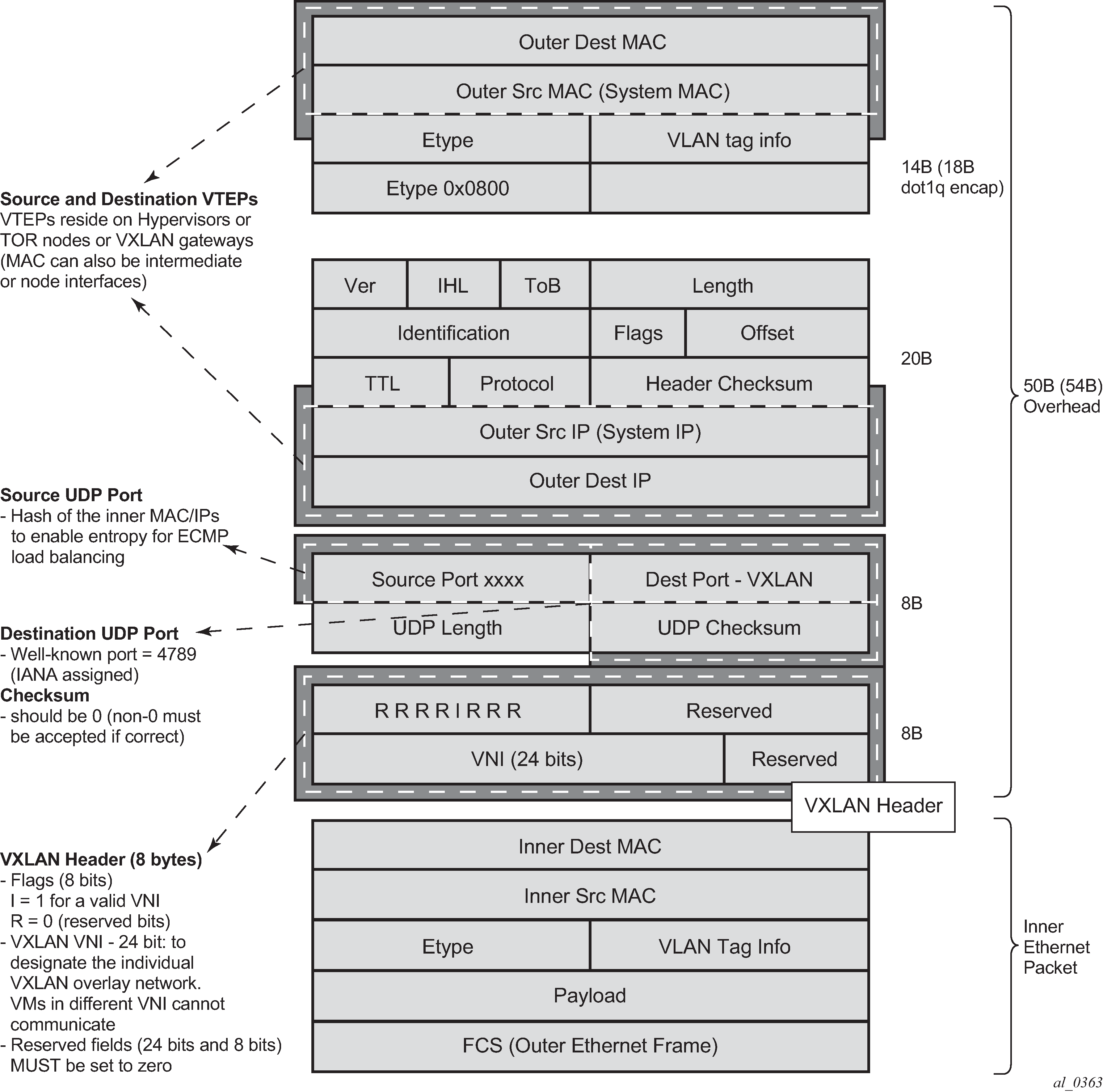
VXLAN encapsulates the inner Ethernet frames into VXLAN + UDP/IP packets. The main pieces of information encoded in this encapsulation are the following:
-
VXLAN header (8 bytes)
-
Flags (8 bits) where the I flag is set to 1 to indicate that the VNI is present and valid. The remaining flags (‟Reserved” bits) are set to 0.
-
Includes the VNI field (24-bit value) or VXLAN network identifier that identifies an isolated Layer 2 domain within the DC network.
-
Remaining fields are reserved for future use.
-
-
UDP header (8 bytes)
-
The destination port is a well-known UDP port assigned by IANA (4789).
-
The source port is derived from a hashing of the inner source and destination MAC/IP addresses that the 7705 SAR Gen 2 does at ingress. This creates an ‟entropy” value that can be used by the core DC nodes for load balancing on ECMP paths.
-
The checksum is set to zero.
-
-
Outer IP and Ethernet headers (34 or 38 bytes)
-
The source IP and source MAC addresses identify the source VTEP. That is, these fields are populated with the PE system IP and chassis MAC address.
Note: The source MAC address is changed on all the IP hops along the path, as is typical in regular IP routing. -
The destination IP identifies the remote VTEP (remote system IP) and is the result of the destination MAC lookup in the service Forwarding Database (FDB).
Note: All remote MACs are learned by the EVPN BGP and associated with a remote VTEP address and VNI.
-
Some considerations related to the support of VXLAN are:
-
VXLAN is only supported on network or hybrid ports with null or dot1q encapsulation.
-
VXLAN is supported on Ethernet/LAG and POS/APS.
-
IPv4 and IPv6 unicast addresses are supported as VTEPs.
-
By default, system IP addresses are supported, as VTEPs, for originating and terminating VXLAN tunnels. Non-system IPv4 and IPv6 addresses are supported by using a Forwarding Path Extension (FPE).
VXLAN ECMP and LAG
The DGW supports ECMP load balancing to reach the destination VTEP. Also, any intermediate core node in the DC should be able to provide further load balancing across ECMP paths, because the source UDP port of each tunneled packet is derived from a hash of the customer inner packet. The following must be considered:
-
ECMP for VXLAN is supported on VPLS services but not for BUM traffic. Unicast spraying is based on the packet contents.
-
ECMP for VXLAN on R-VPLS services is supported for VXLAN IPv6 tunnels.
-
ECMP for VXLAN IPv4 tunnels on R-VPLS is only supported if the configure service vpls allow-ip-int-bind vxlan-ipv4-tep-ecmp command is enabled on the R-VPLS (as well as configure router ecmp).
-
ECMP for Layer 3 multicast traffic on R-VPLS services with EVPN-VXLAN destinations is only supported if the vpls allow-ip-int-bind ip-multicast-ecmp command is enabled (as well as configure router ecmp).
-
In the cases where ECMP is not supported (BUM traffic in VPLS and ECMP on R-VPLS if not enabled), each VXLAN binding is tied to a single (different) ECMP path, so that in a normal deployment with a reasonable number of remote VTEPs, there should be a fair distribution of the traffic across the paths. That is, only per-VTEP load-balancing is supported, instead of per-flow load-balancing.
-
LAG spraying based on the packet hash is supported in all the cases (VPLS unicast, VPLS BUM, and R-VPLS).
VXLAN VPLS tag handling
The following describes the behavior with respect to VLAN tag handling for VXLAN VPLS services:
-
Dot1q, QinQ, and null SAPs, as well as regular VLAN-handling procedures at the WAN side, are supported on VXLAN VPLS services.
-
No ‟vc-type vlan” like VXLAN VNI bindings are supported. Therefore, at the egress of the VXLAN network port, the router does not add any inner VLAN tag on top of the VXLAN encapsulation, and at the ingress network port, the router ignores any VLAN tag received and handles it as part of the payload.
VXLAN MTU considerations
For VXLAN VPLS services, the network port MTU must be at least 50 Bytes (54 Bytes if dot1q) greater than the service MTU to allow enough room for the VXLAN encapsulation.
The service MTU is only enforced on SAPs (any SAP ingress packet with MTU greater than the service MTU is discarded) and not on VXLAN termination (any VXLAN ingress packet makes it to the egress SAP regardless of the configured service MTU).
If BGP-EVPN is enabled in a VXLAN VPLS service, the service MTU can be advertised in the Inclusive Multicast Ethernet Tag routes and enforce that all the routers attached to the same EVPN service have the same service MTU configured.
VXLAN QoS
VXLAN is a network port encapsulation; therefore, the QoS settings for VXLAN are controlled from the network QoS policies.
Ingress
The network ingress QoS policy can be applied either to the network interface over which the VXLAN traffic arrives or under vxlan/network/ingress within the EVPN service.
Regardless of where the network QoS policy is applied, the ingress network QoS policy is used to classify the VXLAN packets based on the outer dot1p (if present), then the outer DSCP, to yield an FC/profile.
If the ingress network QoS policy is applied to the network interface over which the VXLAN traffic arrives then the VXLAN unicast traffic uses the network ingress queues configured on FP where the network interface resides. QoS control of BUM traffic received on the VXLAN tunnels is possible by separately redirecting these traffic types to policers within an FP ingress network queue group. This QoS control uses the per forwarding class fp-redirect-group parameter together with broadcast-policer, unknown-policer, and mcast-policer within the ingress section of a network QoS policy. This QoS control applies to all BUM traffic received for that forwarding class on the network IP interface on which the network QoS policy is applied.
The ingress network QoS policy can also be applied within the EVPN service by referencing an FP queue group instance, as follows:
configure
    service
        vpls <service-id>
            vxlan vni <vni-id>
                network
                    ingress
                        qos <network-policy-id>
                            fp-redirect-group <queue-group-name>
                                     instance <instance-id>
In this case, the redirection to a specific ingress FP queue group applies as a single entity (per forwarding class) to all VXLAN traffic received only by this service. This overrides the QoS applied to the related network interfaces for traffic arriving on VXLAN tunnels in that service but does not affect traffic received on a spoke SDP in the same service. It is possible to also redirect unicast traffic to a policer using the per forwarding class fp-redirect-group policer parameter, as well as the BUM traffic as above, within the ingress section of a network QoS policy. The use of ler-use-dscp, ip-criteria and ipv6-criteria statements are ignored if configured in the ingress section of the referenced network QoS policy. If the instance of the named queue group template referenced in the qos command is not configured on an FP receiving the VXLAN traffic, then the traffic uses the ingress network queues or queue group related to the network interface.
Egress
On egress, there is no need to specify ‟remarking” in the policy to mark the DSCP. This is because the VXLAN adds a new IPv4 header, and the DSCP is always marked based on the egress network qos policy.
VXLAN ping
A new VXLAN troubleshooting tool, VXLAN Ping, is available to verify VXLAN VTEP connectivity. The VXLAN Ping command is available from interactive CLI and SNMP.
This tool allows the user to specify a wide range of variables to influence how the packet is forwarded from the VTEP source to VTEP termination. The ping function requires the user to specify a different test-id (equates to originator handle) for each active and outstanding test. The required local service identifier from which the test is launched determines the source IP (the system IP address) to use in the outer IP header of the packet. This IP address is encoded into the VXLAN header Source IP TLV. The service identifier also encodes the local VNI. The outer-ip-destination must equal the VTEP termination point on the remote node, and the dest-vni must be a valid VNI within the associated service on the remote node. The outer source IP address is automatically detected and inserted in the IP header of the packet. The outer source IP address uses the IPv4 system address by default.
If the VTEP is created using a non-system source IP address through the vxlan-src-vtep command, the outer source IP address uses the address specified by vxlan-src-vtep. The remainder of the variables are optional.
The VXLAN PDU is encapsulated in the appropriate transport header and forwarded within the overlay to the appropriate VTEP termination. The VXLAN router alert (RA) bit is set to prevent forwarding OAM PDU beyond the terminating VTEP. Because handling of the router alert bit was not defined in some early releases of VXLAN implementations, the VNI Informational bit (I-bit) is set to ‟0” for OAM packets. This indicates that the VNI is invalid, and the packet should not be forwarded. This safeguard can be overridden by including the i-flag-on option that sets the bit to ‟1”, valid VNI. Ensure that OAM frames meant to be contained to the VTEP are not forwarded beyond its endpoints.
The supporting VXLAN OAM ping draft includes a requirement to encode a reserved IEEE MAC address as the inner destination value. However, at the time of implementation, that IEEE MAC address had not been assigned. The inner IEEE MAC address defaults to 00:00:00:00:00:00, but may be changed using the inner-l2 option. Inner IEEE MAC addresses that are included with OAM packets are not learned in the local Layer 2 forwarding databases.
The echo responder terminates the VXLAN OAM frame, and takes the appropriate response action, and include relevant return codes. By default, the response is sent back using the IP network as an IPv4 UDP response. The user can choose to override this default by changing the reply-mode to overlay. The overlay return mode forces the responder to use the VTEP connection representing the source IP and source VTEP. If a return overlay is not available, the echo response is dropped by the responder.
Support is included for:
IPv4 VTEP
Optional specification of the outer UDP Source, which helps downstream network elements along the path with ECMP to hash to flow to the same path
Optional configuration of the inner IP information, which helps the user test different equal paths where ECMP is deployed on the source. A test only validates a single path where ECMP functions are deployed. The inner IP information is processed by a hash function, and there is no guarantee that changing the IP information between tests selects different paths.
Optional end system validation for a single L2 IEEE MAC address per test. This function checks the remote FDB for the configured IEEE MAC Address. Only one end system IEEE MAC Address can be configured per test.
Reply mode UDP (default) or Overlay
Optional additional padding can be added to each packet. There is an option that indicates how the responder should handle the pad TLV. By default, the padding is not reflected to the source. The user can change this behavior by including the reflect-pad option. The reflect-pad option is not supported when the reply mode is set to UDP.
Configurable send counts, intervals, times outs, and forwarding class
The VXLAN OAM PDU includes two timestamps. These timestamps are used to report forward direction delay. Unidirectional delay metrics require accurate time of day clock synchronization. Negative unidirectional delay values are reported as ‟0.000”. The round trip value includes the entire round trip time including the time that the remote peer takes to process that packet. These reported values may not be representative of network delay.
The following example commands and outputs show how the VXLAN Ping function can be used to validate connectivity. The echo output includes a new header to better describe the VXLAN ping packet headers and the various levels.
oam vxlan-ping test-id 1 service 1 dest-vni 2 outer-ip-destination 10.20.1.4
interval
0.1 send-count 10

TestID 1, Service 1, DestVNI 2, ReplyMode UDP, IFlag Off, PadSize 0, ReflectPad No,
SendCount 10, Interval 0.1, Timeout 5
Outer: SourceIP 10.20.1.3, SourcePort Dynamic, DestIP 10.20.1.4, TTL 10, FC be, Prof
ile
In
Inner: DestMAC 00:00:00:00:00:00, SourceIP 10.20.1.3, DestIP 127.0.0.1

! ! ! ! ! ! ! ! ! !
---- vxlan-id 2 ip-address 10.20.1.4 PING Statistics ----
10 packets transmitted, 10 packets received, 0.00% packet loss
   10 non-errored responses(!), 0 out-of-order(*), 0 malformed echo responses(.)
   0 send errors(.), 0 time outs(.)
   0 overlay segment not found, 0 overlay segment not operational
forward-delay min = 1.097ms, avg = 2.195ms, max = 2.870ms, stddev = 0.735ms
round-trip-delay min = 1.468ms, avg = 1.693ms, max = 2.268ms, stddev = 0.210ms


oam vxlan-ping test-id 2 service 1 dest-vni 2 outer-ip-destination 10.20.1.4 outer-
ip-source-udp 65000 outer-ip-ttl 64 inner-l2 d0:0d:1e:00:00:01 inner-ip-source
 192.168.1.2 inner-ip-destination 127.0.0.8 reply-mode overlay send-count 20
interval
 1 timeout 3 padding 1000 reflect-pad fc nc profile out

TestID 2, Service 1, DestVNI 2, ReplyMode overlay, IFlag Off, PadSize 1000, ReflectP
ad
 Yes, SendCount 20, Interval 1, Timeout 3
Outer: SourceIP 10.20.1.3, SourcePort 65000, DestIP 10.20.1.4, TTL 64, FC nc, Profil
e
 out
Inner: DestMAC d0:0d:1e:00:00:01, SourceIP 192.168.1.2, DestIP 127.0.0.8

===================================================================================
rc=1 Malformed Echo Request Received, rc=2 Overlay Segment Not Present, rc=3 Overlay
 Segment Not Operational, rc=4 Ok
===================================================================================
1132 bytes from vxlan-id 2 10.20.1.4: vxlan_seq=1 ttl=255 rtt-time=1.733ms fwd
-time=0.302ms. rc=4
1132 bytes from vxlan-id 2 10.20.1.4: vxlan_seq=2 ttl=255 rtt-time=1.549ms fwd
-time=1.386ms. rc=4
1132 bytes from vxlan-id 2 10.20.1.4: vxlan_seq=3 ttl=255 rtt-time=3.243ms fwd
-time=0.643ms. rc=4
1132 bytes from vxlan-id 2 10.20.1.4: vxlan_seq=4 ttl=255 rtt-time=1.551ms fwd
-time=2.350ms. rc=4
1132 bytes from vxlan-id 2 10.20.1.4: vxlan_seq=5 ttl=255 rtt-time=1.644ms fwd
-time=1.080ms. rc=4
1132 bytes from vxlan-id 2 10.20.1.4: vxlan_seq=6 ttl=255 rtt-time=1.670ms fwd
-time=1.307ms. rc=4
1132 bytes from vxlan-id 2 10.20.1.4: vxlan_seq=7 ttl=255 rtt-time=1.636ms fwd
-time=0.490ms. rc=4
1132 bytes from vxlan-id 2 10.20.1.4: vxlan_seq=8 ttl=255 rtt-time=1.649ms fwd
-time=0.005ms. rc=4
1132 bytes from vxlan-id 2 10.20.1.4: vxlan_seq=9 ttl=255 rtt-time=1.401ms fwd
-time=0.685ms. rc=4
1132 bytes from vxlan-id 2 10.20.1.4: vxlan_seq=10 ttl=255 rtt-time=1.634ms fwd
-time=0.373ms. rc=4
1132 bytes from vxlan-id 2 10.20.1.4: vxlan_seq=11 ttl=255 rtt-time=1.559ms fwd
-time=0.679ms. rc=4
1132 bytes from vxlan-id 2 10.20.1.4: vxlan_seq=12 ttl=255 rtt-time=1.666ms fwd
-time=0.880ms. rc=4
1132 bytes from vxlan-id 2 10.20.1.4: vxlan_seq=13 ttl=255 rtt-time=1.629ms fwd
-time=0.669ms. rc=4
1132 bytes from vxlan-id 2 10.20.1.4: vxlan_seq=14 ttl=255 rtt-time=1.280ms fwd
-time=1.029ms. rc=4
1132 bytes from vxlan-id 2 10.20.1.4: vxlan_seq=15 ttl=255 rtt-time=1.458ms fwd
-time=0.268ms. rc=4
1132 bytes from vxlan-id 2 10.20.1.4: vxlan_seq=16 ttl=255 rtt-time=1.659ms fwd
-time=0.786ms. rc=4
1132 bytes from vxlan-id 2 10.20.1.4: vxlan_seq=17 ttl=255 rtt-time=1.636ms fwd
-time=1.071ms. rc=4
1132 bytes from vxlan-id 2 10.20.1.4: vxlan_seq=18 ttl=255 rtt-time=1.568ms fwd
-time=2.129ms. rc=4
1132 bytes from vxlan-id 2 10.20.1.4: vxlan_seq=19 ttl=255 rtt-time=1.657ms fwd
-time=1.326ms. rc=4
1132 bytes from vxlan-id 2 10.20.1.4: vxlan_seq=20 ttl=255 rtt-time=1.762ms fwd
-time=1.335ms. rc=4

---- vxlan-id 2 ip-address 10.20.1.4 PING Statistics ----
20 packets transmitted, 20 packets received, 0.00% packet loss
   20 valid responses, 0 out-of-order, 0 malformed echo responses
   0 send errors, 0 time outs
   0 overlay segment not found, 0 overlay segment not operational
forward-delay min = 0.005ms, avg = 0.939ms, max = 2.350ms, stddev = 0.577ms
round-trip-delay min = 1.280ms, avg = 1.679ms, max = 3.243ms, stddev = 0.375ms


oam vxlan-ping test-id 1 service 1 dest-vni 2 outer-ip-destination 10.20.1.4 send
-count 10 end-system 00:00:00:00:00:01 interval 0.1
TestID 1, Service 1, DestVNI 2, ReplyMode UDP, IFlag Off, PadSize 0, ReflectPad No,
 EndSystemMAC 00:00:00:00:00:01, SendCount 10, Interval 0.1, Timeout 5
Outer: SourceIP 10.20.1.3, SourcePort Dynamic, DestIP 10.20.1.4, TTL 10, FC be, Prof
ile
 In
Inner: DestMAC 00:00:00:00:00:00, SourceIP 10.20.1.3, DestIP 127.0.0.1

2 2 2 2 2 2 2 2 2 2
---- vxlan-id 2 ip-address 10.20.1.4 PING Statistics ----
10 packets transmitted, 10 packets received, 0.00% packet loss
   10 non-errored responses(!), 0 out-of-order(*), 0 malformed echo responses(.)
   0 send errors(.), 0 time outs(.)
   0 overlay segment not found, 0 overlay segment not operational
   0 end-system present(1), 10 end-system not present(2)
forward-delay min = 0.467ms, avg = 0.979ms, max = 1.622ms, stddev = 0.504ms
round-trip-delay min = 1.501ms, avg = 1.597ms, max = 1.781ms, stddev = 0.088ms


oam vxlan-ping test-id 1 service 1 dest-vni 2 outer-ip-destination 10.20.1.4 send
-count 10 end-system 00:00:00:00:00:01
TestID 1, Service 1, DestVNI 2, ReplyMode UDP, IFlag Off, PadSize 0, ReflectPad No,
 EndSystemMAC 00:00:00:00:00:01, SendCount 10, Interval 1, Timeout 5
Outer: SourceIP 10.20.1.3, SourcePort Dynamic, DestIP 10.20.1.4, TTL 10, FC be, Prof
ile
 In
Inner: DestMAC 00:00:00:00:00:00, SourceIP 10.20.1.3, DestIP 127.0.0.1

===================================================================================
rc=1 Malformed Echo Request Received, rc=2 Overlay Segment Not Present, rc=3 Overlay
 Segment Not Operational, rc=4 Ok
mac=1 End System Present, mac=2 End System Not Present
===================================================================================

92 bytes from vxlan-id 2 10.20.1.4: vxlan_seq=1 ttl=255 rtt-time=2.883ms fwd
-time=4.196ms. rc=4 mac=2
92 bytes from vxlan-id 2 10.20.1.4: vxlan_seq=2 ttl=255 rtt-time=1.596ms fwd
-time=1.536ms. rc=4 mac=2
92 bytes from vxlan-id 2 10.20.1.4: vxlan_seq=3 ttl=255 rtt-time=1.698ms fwd
-time=0.000ms. rc=4 mac=2
92 bytes from vxlan-id 2 10.20.1.4: vxlan_seq=4 ttl=255 rtt-time=1.687ms fwd
-time=1.766ms. rc=4 mac=2
92 bytes from vxlan-id 2 10.20.1.4: vxlan_seq=5 ttl=255 rtt-time=1.679ms fwd
-time=0.799ms. rc=4 mac=2
92 bytes from vxlan-id 2 10.20.1.4: vxlan_seq=6 ttl=255 rtt-time=1.678ms fwd
-time=0.000ms. rc=4 mac=2
92 bytes from vxlan-id 2 10.20.1.4: vxlan_seq=7 ttl=255 rtt-time=1.709ms fwd
-time=0.031ms. rc=4 mac=2
92 bytes from vxlan-id 2 10.20.1.4: vxlan_seq=8 ttl=255 rtt-time=1.757ms fwd
-time=1.441ms. rc=4 mac=2
92 bytes from vxlan-id 2 10.20.1.4: vxlan_seq=9 ttl=255 rtt-time=1.613ms fwd
-time=2.570ms. rc=4 mac=2
92 bytes from vxlan-id 2 10.20.1.4: vxlan_seq=10 ttl=255 rtt-time=1.631ms fwd
-time=2.130ms. rc=4 mac=2

---- vxlan-id 2 ip-address 10.20.1.4 PING Statistics ----
10 packets transmitted, 10 packets received, 0.00% packet loss
   10 valid responses, 0 out-of-order, 0 malformed echo responses
   0 send errors, 0 time outs
   0 overlay segment not found, 0 overlay segment not operational
   0 end-system present, 10 end-system not present
forward-delay min = 0.000ms, avg = 1.396ms, max = 4.196ms, stddev = 1.328ms
round-trip-delay min = 1.596ms, avg = 1.793ms, max = 2.883ms, stddev = 0.366ms
EVPN-VXLAN routed VPLS multicast routing support
IPv4 and IPv6 multicast routing is supported in an EVPN-VXLAN VPRN and IES routed VPLS service through its IP interface when the source of the multicast stream is on one side of its IP interface and the receivers are on either side of the IP interface. For example, the source for multicast stream G1 could be on the IP side, sending to receivers on both other regular IP interfaces and the VPLS of the routed VPLS service, while the source for group G2 could be on the VPLS side sending to receivers on both the VPLS and IP side of the routed VPLS service. See IPv4 and IPv6 multicast routing support for more details.
IGMP and MLD snooping on VXLAN
The delivery of IP multicast in VXLAN services can be optimized with IGMP and MLD snooping. IGMP and MLD snooping are supported in EVPN-VXLAN VPLS services and in EVPN-VXLAN VPRN/IES R-VPLS services. When enabled, IGMP and MLD reports are snooped on SAPs or SDP bindings, but also on VXLAN bindings, to create or modify entries in the MFIB for the VPLS service.
When configuring IGMP and MLD snooping in EVPN-VXLAN VPLS services, consider the following:
To enable IGMP snooping in the VPLS service on VXLAN, use the configure service vpls igmp-snooping no shutdown command.
To enable MLD snooping in the VPLS service on VXLAN, use the configure service vpls mld-snooping no shutdown command.
The VXLAN bindings only support basic IGMP/MLD snooping functionality. Features configurable under SAPs or SDP bindings are not available for VXLAN (VXLAN bindings are configured with the default values used for SAPs and SDP bindings). By default, a specified VXLAN binding only becomes a dynamic Mrouter when it receives IGMP or MLD queries and adds a specified multicast group to the MFIB when it receives an IGMP or MLD report for that group.
Alternatively, it is possible to configure all VXLAN bindings for a particular VXLAN instance to be Mrouter ports using the configure service vpls vxlan igmp-snooping mrouter-port and configure service vpls vxlan mld-snooping mrouter-port commands.
The show service id igmp-snooping, clear service id igmp-snooping, show service id mld-snooping, and clear service id mld-snooping commands are also available for VXLAN bindings.
Note: MLD snooping uses MAC-based forwarding. See MAC-based IPv6 multicast forwarding for more details.The following CLI commands show how the system displays IGMP snooping information and statistics on VXLAN bindings (the equivalent MLD output is similar).
*A:PE1# show service id 1 igmp-snooping port-db vxlan vtep  192.0.2.72 vni 1 detail
===============================================================================
IGMP Snooping VXLAN 192.0.2.72/1 Port-DB for service 1
===============================================================================
-------------------------------------------------------------------------------
IGMP Group 239.0.0.1
-------------------------------------------------------------------------------
Mode             : exclude              Type             : dynamic
Up Time          : 0d 19:07:05          Expires          : 137s
Compat Mode      : IGMP Version 3
V1 Host Expires  : 0s                   V2 Host Expires  : 0s
-------------------------------------------------------
Source Address  Up Time      Expires  Type     Fwd/Blk
-------------------------------------------------------
No sources.
-------------------------------------------------------------------------------
IGMP Group 239.0.0.2
-------------------------------------------------------------------------------
Mode             : include              Type             : dynamic
Up Time          : 0d 19:06:39          Expires          : 0s
Compat Mode      : IGMP Version 3
V1 Host Expires  : 0s                   V2 Host Expires  : 0s
-------------------------------------------------------
Source Address  Up Time      Expires  Type     Fwd/Blk
-------------------------------------------------------
10.0.0.232      0d 19:06:39  137s     dynamic  Fwd
-------------------------------------------------------------------------------
Number of groups: 2
===============================================================================

*A:PE1# show service id 1 igmp-snooping
statistics vxlan vtep  192.0.2.72 vni 1

===============================================================================
IGMP Snooping Statistics for VXLAN 192.0.2.72/1 (service 1)
===============================================================================
Message Type            Received      Transmitted   Forwarded
-------------------------------------------------------------------------------
General Queries         0             0             556
Group Queries           0             0             0
Group-Source Queries    0             0             0
V1 Reports              0             0             0
V2 Reports              0             0             0
V3 Reports              553           0             0
V2 Leaves               0             0             0
Unknown Type            0             N/A           0
-------------------------------------------------------------------------------
Drop Statistics
-------------------------------------------------------------------------------
Bad Length               : 0
Bad IP Checksum          : 0
Bad IGMP Checksum        : 0
Bad Encoding             : 0
No Router Alert          : 0
Zero Source IP           : 0
Wrong Version            : 0
Lcl-Scope Packets        : 0
Rsvd-Scope Packets       : 0

Send Query Cfg Drops     : 0
Import Policy Drops      : 0
Exceeded Max Num Groups  : 0
Exceeded Max Num Sources : 0
Exceeded Max Num Grp Srcs: 0
MCAC Policy Drops        : 0
===============================================================================
*A:PE1# show service id 1 mfib
===============================================================================
Multicast FIB, Service 1
===============================================================================
Source Address  Group Address         SAP or SDP Id               Svc Id   Fwd/Blk
-------------------------------------------------------------------------------
*               *                     sap:1/1/1:1              Local    Fwd
*               239.0.0.1             sap:1/1/1:1              Local    Fwd
                                      vxlan:192.0.2.72/1       Local    Fwd
10.0.0.232      239.0.0.2             sap:1/1/1:1              Local    Fwd
                                      vxlan:192.0.2.72/1       Local    Fwd
-------------------------------------------------------------------------------
Number of entries: 3
===============================================================================
PIM snooping on VXLAN
PIM snooping for IPv4 and IPv6 are supported in an EVPN-EVPN-VXLAN VPLS or R-VPLS service (with the R-VPLS attached to a VPRN or IES service). The snooping operation is similar to that within a VPLS service (see PIM snooping for VPLS) and supports both PIM snooping and PIM proxy modes.
PIM snooping for IPv4 is enabled using the configure service vpls pim-snooping command.
PIM snooping for IPv6 is enabled using the configure service vpls pim-snooping no ipv6-multicast-disable command.
When using PIM snooping for IPv6, the default forwarding is MAC-based with optional support for SG-based (see IPv6 multicast forwarding). SG-based forwarding requires FP3- or higher-based hardware.
It is not possible to configure max-num-groups for VXLAN bindings.
Static VXLAN termination in Epipe services
By default, the system IP address is used to terminate and generate VXLAN traffic. The following configuration example shows an Epipe service that supports static VXLAN termination:
config service epipe 1 name "epipe1" customer 1 create
  sap 1/1/1:1 create
  exit
  vxlan vni 100 create
    egr-vtep 192.0.2.1
      oper-group op-grp-1
    exit
  no shutdown
Where:
vxlan vni vni create specifies the ingress VNI the router uses to identify packets for the service. The following considerations apply:
In services that use EVPN, the configured VNI is only used as the ingress VNI to identify packets that belong to the service. Egress VNIs are learned from the BGP EVPN. In the case of Static VXLAN, the configured VNI is also used as egress VNI (because there is no BGP EVPN control plane).
The configured VNI is unique in the system, and as a result, it can only be configured in one service (VPLS or Epipe).
egr-vtep ip-address specifies the remote VTEP the router uses when encapsulating frames into VXLAN packets. The following consideration apply:
When the PE receives VXLAN packets, the source VTEP is not checked against the configured egress VTEP.
The ip-address must be present in the global routing table so that the VXLAN destination is operationally up.
The oper-group may be added under egr-vtep. The expected behavior for the operational group and service status is as follows:
If the egr-vtep entry is not present in the routing table, the VXLAN destination (in the show service id vxlan command) and the provisioned operational group under egr-vtep enters into the operationally down state.
If the Epipe SAP goes down, the service goes down, but it is not affected if the VXLAN destination goes down.
If the service is admin shutdown, then in addition to the SAP, the VXLAN destination and the oper-group also enters the operationally down state.
Note: The operational group configured under egr-vtep cannot be monitored on the SAP of the Epipe where it is configured.
The following features are not supported by Epipe services with VXLAN destinations:
per-service hashing
SDP-binds
PBB context
BGP-VPWS
spoke SDP-FEC
PW-port
Static VXLAN termination in VPLS/R-VPLS services
VXLAN instances in VPLS and R-VPLS can be configured with egress VTEPs. This is referred as static vxlan-instances. The following configuration example shows a VPLS service that supports a static vxlan-instance:
config service vpls 1 name "vpls-1" customer 1 create
  sap 1/1/1:1 create
  exit
  vxlan instance 1 vni 100 create
    source-vtep-security
    no disable-aging /* default: disable-aging
    no disable-learning  /* default: disable-learning
    no discard-unknown-source
    no max-nbr-mac-addr <table-size>
    restrict-protected-src discard-frame
    egr-vtep 192.0.2.1 create
    exit
    egr-vtep 192.0.2.2 create
    exit
  vxlan instance 2 vni 101 create
    egr-vtep 192.0.2.3 create
    exit

 vxlan instance 2 vni 101 create
    egr-vtep 192.0.2.3 create
    exit
  no shutdown
Specifically the following can be stated:
Each VPLS service can have up to two static VXLAN instances. Each instance is an implicit split-horizon-group, and up to 255 static VXLAN binds are supported in total, shared between the two VXLAN instances.
Single VXLAN instance VPLS services with static VXLAN are supported along with SAPs and SDP bindings. Therefore:
VNIs configured in static VXLAN instances are ‟symmetric”, that is, the same ingress and egress VNIs are used for VXLAN packets using that instance. Note that asymmetric VNIs are actually possible in EVPN VXLAN instances.
The addresses can be IPv4 or IPv6 (but not a mix within the same service).
A specified VXLAN instance can be configured with static egress VTEPs, or be associated with BGP EVPN, but the same instance cannot be configured to support both static and BGP-EVPN based VXLAN bindings.
Up to two VXLAN instances are supported per VPLS (up to two).
When two VXLAN instances are configured in the same VPLS service, any combination of static and BGP-EVPN enabled instances are supported. That is, the two VXLAN instances can be static, or BGP-EVPN enabled, or one of each type.
When a service is configured with EVPN and there is a static BGP-EVPN instance in the same service, the user must configure restrict-protected-src discard-frame along with no disable-learning in the static BGP-EVPN instance, service>vpls>vxlan.
MAC addresses are learned also on the VXLAN bindings of the static VXLAN instance. Therefore, they are shown in the FDB commands. Note that disable-learning and disable-aging are by default enabled in static vxlan-instance.
The learned MAC addresses are subject to the remote-age, and not the local-age (only MACs learned on SAPs use the local-age setting).
MAC addresses are learned on a VTEP as long as no disable-learning is configured, and the VXLAN VTEP is present in the base route table. When the VTEP disappears from the route table, the associated MACs are flushed.
The vpls vxlan source-vtep-security command can be configured per VXLAN instance on VPLS services. When enabled, the router performs an IPv4 source-vtep lookup to discover if the VXLAN packet comes from a trusted VTEP. If not, the router discards the frame. If the lookup yields a trusted source VTEP, then the frame is accepted.
A trusted VTEP is an egress VTEP that has been statically configured, or dynamically learned (through EVPN) in any service, Epipe or VPLS
The command show service vxlan shows the list of trusted VTEPs in the router.
The command source-vtep-security works for static VXLAN instances or BGP-EVPN enabled VXLAN instances, but only for IPv4 VTEPs.
The command is mutually exclusive with assisted-replication (replicator or leaf) in the VNI instance. AR can still be configured in a different instance.
Static VXLAN instances can use non-system IPv4/IPv6 termination.
Non-system IPv4 and IPv6 VXLAN termination in VPLS, R-VPLS, and Epipe services
By default, only VXLAN packets with the same IP destination address as the system IPv4 address of the router can be terminated and processed for a subsequent MAC lookup. A router can simultaneously terminate VXLAN tunnels destined for its system IP address and three additional non-system IPv4 or IPv6 addresses, which can be on the base router or VPRN instances. This section describes the configuration requirements for services to terminate VXLAN packets destined for a non-system loopback IPv4 or IPv6 address on the base router or VPRN.
- Create the FPE (see FPE creation)
- Associate the FPE with VXLAN termination (see FPE association with VXLAN termination)
- Configure the router loopback interface (see VXLAN router loopback interface)
- Configure VXLAN termination (non-system) VTEP addresses (see VXLAN termination VTEP addresses)
- Add the service configuration (see VXLAN services)
-
FPE creation
A Forwarding Path Extension (FPE) is required to terminate non-system IPv4 or IPv6 VXLAN tunnels.
In a non-system IPv4 VXLAN termination, the FPE function is used for additional processing required at ingress (VXLAN tunnel termination) only, and not at egress (VXLAN tunnel origination).
If the IPv6 VXLAN terminates on a VPLS or Epipe service, the FPE function is used at ingress only, and not at egress.
For R-VPLS services terminating IPv6 VXLAN tunnels and also for VPRN VTEPs, the FPE is used for the egress as well as the VXLAN termination function. In the case of R-VPLS, an internal static SDP is created to allow the required extra processing.
For information about FPE configuration and functions, see the 7705 SAR Gen 2 Interface Configuration Guide, "Forwarding Path Extension".
-
FPE association with VXLAN termination
The FPE must be associated with the VXLAN termination application. The following example configuration shows two FPEs and their corresponding association. FPE 1 uses the base router and FPE 2 is configured for VXLAN termination on VPRN 10.
configure fwd-path-ext fpe 1 create path pxc pxc-1 vxlan-termination fpe 2 create path pxc pxc-2 vxlan-termination router 10 -
VXLAN router loopback interface
Create the interface that terminates and originates the VXLAN packets. The interface is created as a router interface, which is added to the Interior Gateway Protocol (IGP) and used by the BGP as the EVPN NLRI next hop.
Because the system cannot terminate the VXLAN on a local interface address, a subnet must be assigned to the loopback interface and not a host IP address that is /32 or /128. In the following example, all the addresses in subnet 11.11.11.0/24 (except 11.11.11.1, which is the interface IP) and subnet 10.1.1.0/24 (except 10.1.1.1) can be used for tunnel termination. The subnet is advertised using the IGP and is configured on either the base router or a VPRN. In the example, two subnets are assigned, in the base router and VPRN 10 respectively.
configure
  router
       interface "lo1"
            loopback
            address 10.11.11.1/24
       isis
            interface "lo1"
                 passive
                 no shutdown
configure service vprn 10 name "vprn10" customer 1 create interface "lo1" loopback address 10.1.1.1/24 isis interface "lo1" passive no shutdownA local interface address cannot be configured as a VXLAN tunnel-termination IP address in the CLI, as shown in the following example.
*A:PE-3# configure service system vxlan tunnel-termination 192.0.2.3 fpe 1 create
MINOR: SVCMGR #8353 VXLAN Tunnel termination IP address cannot be configured -
 IP address in use by another application or matches a local interface IP address
The subnet can be up to 31 bits. For example, to use 10.11.11.1 as the VXLAN termination address, the subnet should be configured and advertised as shown in the following example configuration.
 interface "lo1"
            address 10.11.11.0/31
            loopback
            no shutdown
        exit
        isis 0
            interface "lo1"
                passive
                no shutdown
            exit
            no shutdown
        exit
It is not a requirement for the remote PEs and NVEs to have the specific /32 or /128 IP address in their RTM to resolve the BGP EVPN NLRI next hop or forward the VXLAN packets. An RTM with a subnet that contains the remote VTEP can also perform these tasks.
Note: The system does not check for a pre-existing local base router loopback interface with a subnet corresponding to the VXLAN tunnel termination address. If a tunnel termination address is configured and the FPE is operationally up, the system starts terminating VXLAN traffic and responding ICMP messages for that address. The following conditions are ignored in this scenario:-
the presence of a loopback interface in the base router
-
the presence of an interface with the address contained in the configured subnet, and no loopback
The following example output includes an IPv6 address in the base router. It could also be configured in a VPRN instance.
configure router interface "lo1" loopback address 10.11.11.1/24 ipv6 address 2001:db8::/127 exit isis interface "lo1" passive no shutdown -
-
VXLAN termination VTEP addresses
The service>system>vxlan>tunnel-termination context allows the user to configure non-system IP addresses that can terminate the VXLAN and their corresponding FPEs.
As shown in the following example, an IP address may be associated with a new or existing FPE already terminating the VXLAN. The list of addresses that can terminate the VXLAN can include IPv4 and IPv6 addresses.
config service system vxlan#
       tunnel-termination 10.11.11.1 fpe 1 create
       tunnel-termination 2001:db8:1000::1 fpe 1 create

config service vprn 10 vxlan#
       tunnel-termination 10.1.1.2 fpe 2 create
The tunnel-termination command creates internal loopback interfaces that can respond to ICMP requests. In the following sample output, an internal loopback is created when the tunnel termination address is added (for 10.11.11.1 and 2001:db8:1000::1). The internal FPE router interfaces created by the VXLAN termination function are also shown in the output. Similar loopback and interfaces are created for tunnel termination addresses in a VPRN (not shown).
*A:PE1# show router interface =============================================================================== Interface Table (Router: Base) =============================================================================== Interface-Name Adm Opr(v4/v6) Mode Port/SapId IP-Address PfxState ------------------------------------------------------------------------------- _tmnx_fpe_1.a Up Up/Up Network pxc-2.a:1 fe80::100/64 PREFERRED _tmnx_fpe_1.b Up Up/Up Network pxc-2.b:1 fe80::101/64 PREFERRED _tmnx_vli_vxlan_1_131075 Up Up/Up Network loopback 10.11.11.1/32 n/a 2001:db8:1000::1 PREFERRED fe80::6cfb:ffff:fe00:0/64 PREFERRED lo1 Up Up/Down Network loopback 10.11.11.0/31 n/a system Up Up/Down Network system 1.1.1.1/32 n/a <snip> -
VXLAN services
By default, the VXLAN services use the system IP address as the source VTEP of the VXLAN encapsulated frames. The vxlan-src-vtep command in the config>service>vpls or config>service>epipe context enables the system to use a non-system IPv4 or IPv6 address as the source VTEP for the VXLAN tunnels in that service.
A different vxlan-src-vtep can be used for different services, as shown in the following example where two different services use different non-system IP addresses as source VTEPs.
configure service vpls 1
   vxlan-src-vtep 10.11.11.1

configure service vpls 2
   vxlan-src-vtep 2001:db8:1000::1
In addition, if a vxlan-src-vtep is configured and the service uses EVPN, the IP address is also used to set the BGP NLRI next hop in EVPN route advertisements for the service.
Note: The BGP EVPN next hop can be overridden by the use of export policies based on the following rules:-
A BGP peer policy can override a next hop pushed by the vxlan-src-vtep configuration.
-
If the VPLS service is IPv6 (that is, the vxlan-src-vtep is IPv6) and a BGP peer export policy is configured with next-hop-self, the BGP next-hop is overridden with an IPv6 address auto-derived from the IP address of the system. The auto-derivation is based on RFC 4291. For example, ::ffff:10.20.1.3 is auto-derived from system IP 10.20.1.3.
-
The policy checks the address type of the next hop provided by the vxlan-src-vtep command. If the command provides an IPv6 next hop, the policy is unable use an IPv4 address to override the IPv6 address provided by the vxlan-src-vtep command.
After the preceding steps are performed to configure a VXLAN termination, the VPLS, R-VPLS, or Epipe service can be used normally, except that the service terminates VXLAN tunnels with a non-system IPv4 or IPv6 destination address (in the base router or a VPRN instance) instead of the system IP address only.
The FPE vxlan-termination function creates internal router interfaces and loopbacks that are displayed by the show commands. When configuring IPv6 VXLAN termination on an R-VPLS service, as well as the internal router interfaces and loopbacks, the system creates internal SDP bindings for the required egress processing. The following output shows an example of an internal FPE-type SDP binding created for IPv6 R-VPLS egress processing.
*A:PE1# show service sdp-using
===============================================================================
SDP Using
===============================================================================
SvcId      SdpId              Type   Far End              Opr   I.Label E.Label
                                                          State
-------------------------------------------------------------------------------
2002       17407:2002         Fpe    fpe_1.b              Up    262138  262138
-------------------------------------------------------------------------------
Number of SDPs : 1
-------------------------------------------------------------------------------
===============================================================================
When BGP EVPN is used, the BGP peer over which the EVPN-VXLAN updates are received can be an IPv4 or IPv6 peer, regardless of whether the next-hop is an IPv4 or IPv6 address.
The same VXLAN tunnel termination address cannot be configured on different router instances; that is, on two different VPRN instances or on a VPRN and the base router.
-
EVPN for overlay tunnels
This section describes the specifics of EVPN for non-MPLS Overlay tunnels.
BGP-EVPN control plane for VXLAN overlay tunnels
RFC 8365 describes EVPN as the control plane for overlay-based networks. The 7705 SAR Gen 2 supports all routes and features described in RFC 7432 that are required for the DGW function. EVPN multihoming and BGP multihoming based on the L2VPN BGP address family are both supported if redundancy is needed.
The following figure shows the EVPN MP-BGP NLRI, required attributes and extended communities, and two route types supported for the DGW Layer 2 applications:
- route type 3
- Inclusive Multicast Ethernet Tag (IMET) route
- route type 2
- MAC/IP advertisement route
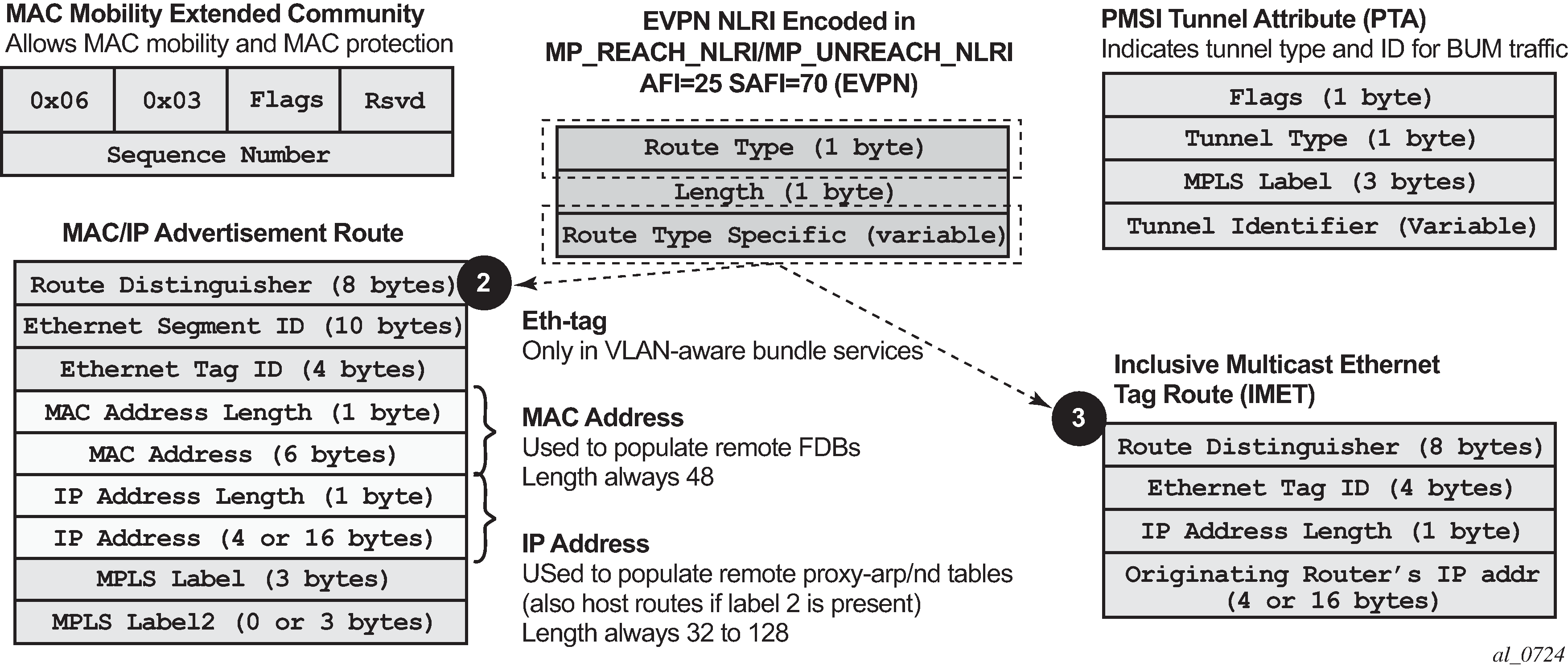
EVPN route type 3 – IMET route
Route type 3 is used to set up the flooding tree (BUM flooding) for a specified VPLS service in the data center. The received inclusive multicast routes add entries to the VPLS flood list. The tunnel types supported in an EVPN route type 3 when BGP-EVPN MPLS is enabled are ingress replication, P2MP MLDP, and composite tunnels.
Ingress Replication (IR) and Assisted Replication (AR) are supported for VXLAN tunnels. See Layer 2 multicast optimization for VXLAN (Assisted-Replication) for more information about the AR.
If ingress-repl-inc-mcast-advertisement is enabled, a route type 3 is generated by the router per VPLS service as soon as the service is in an operationally up state. The following fields and values are used:
-
Route Distinguisher is taken from the RD of the VPLS service within the BGP context.
Note: The RD can be configured or derived from the bgp-evpn evi value. -
Ethernet Tag ID is 0.
-
IP address length is always 32.
-
Originating router’s IP address carries an IPv4 or IPv6 address.
Note: By default, the IP address of the Originating router is derived from the system IP address. However, this can be overridden by the configure service vpls bgp-evpn incl-mcast-orig-ip ip-address command for the Ingress Replication (and mLDP if MPLS is used) tunnel type. -
For PMSI Tunnel Attribute (PTA), tunnel type = Ingress replication (6) or Assisted Replication (10). The following applies:
-
Leaf is not required for Flags.
-
MPLS label carries the VNI configured in the VPLS service. Only one VNI can be configured per VPLS service.
-
Tunnel endpoint is equal to the system IP address.
-
As shown in the following figure, additional flags are used in the PTA when the service is configured for AR.
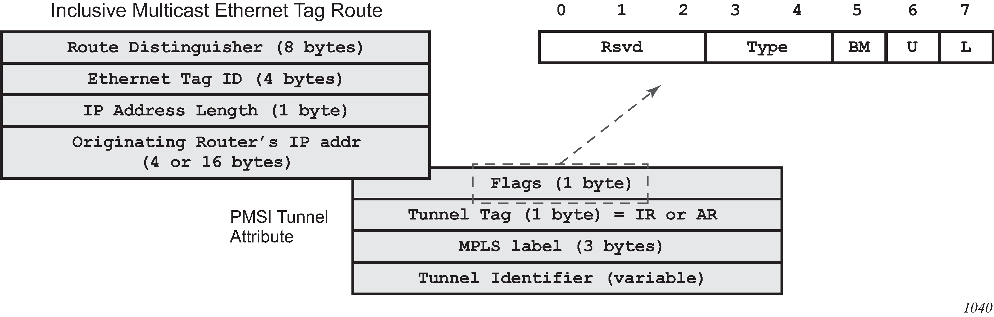
The Flags field is defined as a Type field (for AR) with two new flags that are defined as follows:
-
T is the AR Type field (2 bits):
-
00 (decimal 0) = RNVE (non-AR support)
-
01 (decimal 1) = AR REPLICATOR
-
10 (decimal 2) = AR LEAF
-
-
The U and BM flags defined in IETF Draft draft-ietf-bess-evpn-optimized-ir are not used in the SR OS.
The following table describes the inclusive multicast route information sent per VPLS service when the router is configured as assisted-replication replicator (AR-R) or assisted-replication leaf (AR-L). A Regular Network Virtualization Edge device (RNVE) is defined as an EVPN-VXLAN router that does not support (or is not configured for) Assisted-Replication.
| AR role | Function | Inclusive Mcast routes advertisement |
|---|---|---|
|
AR-R |
Assists AR-LEAFs |
|
|
AR-LEAF |
Sends BM only to AR-Rs |
IR inclusive multicast route (IR IP, T=2) if ingress-repl-inc-mcast-advertisement is enabled |
|
RNVE |
Non-AR support |
IR inclusive multicast route (IR IP) if ingress-repl-inc-mcast-advertisement is enabled |
EVPN route type 2 – MAC/IP advertisement route
The 7705 SAR Gen 2 generates this route type for advertising MAC addresses. If mac-advertisement is enabled, the router generates MAC advertisement routes for the following:
-
learned MACs on SAPs or SDP bindings
-
conditional static MACs
The route type 2 generated by a router uses the following fields and values:
-
Route Distinguisher is taken from the RD of the VPLS service within the BGP context.
Note: The RD can be configured or derived from the bgp-evpn evi value. -
Ethernet Segment Identifier (ESI) value = 0:0:0:0:0:0:0:0:0:0 or non-zero, depending on whether the MAC addresses are learned on an Ethernet Segment.
-
Ethernet Tag ID is 0.
-
MAC address length is always 48.
-
MAC Address:
-
is 00:00:00:00:00:00 for the Unknown MAC route address.
-
is different from 00:…:00 for the rest of the advertised MACs.
-
-
IP address and IP address length:
-
The length of the IP address associated with the MAC being advertised is either 32 for IPv4 or 128 for IPv6.
-
If the MAC address is the Unknown MAC route, the IP address length is zero and the IP omitted.
-
In general, any MAC route without IP has IPL=0 (IP length) and the IP is omitted.
-
When received, any IPL value not equal to zero, 32, or 128 discards the route.
-
-
MPLS Label 1 carries the VNI configured in the VPLS service. Only one VNI can be configured per VPLS.
-
MPLS Label 2 is 0.
-
MAC Mobility extended community is used to signal the sequence number in case of MAC moves and the sticky bit in case of advertising conditional static MACs. If a MAC route is received with a MAC mobility ext-community, the sequence number and the sticky bit are considered for route selection.
When EVPN-VXLAN multihoming is enabled, type 1 routes (Auto-Discovery per-ES and per-EVI routes) and type 4 routes (ES routes) are also generated and processed. See BGP-EVPN control plane for MPLS tunnels for more information about route types 1 and 4.
EVPN route type 5 – IP prefix route
The following figure shows the IP prefix route or route-type 5.

The router generates this route type to advertise IP prefixes in EVPN. The IP prefix advertisement routes are generated for existing IP prefixes in a VPRN linked to the IRB backhaul R-VPLS service.
The route-type 5 generated by a router uses the following fields and values:
-
Route Distinguisher: taken from the RD configured in the IRB backhaul R-VPLS service within the BGP context
-
Ethernet Segment Identifier (ESI): value = 0:0:0:0:0:0:0:0:0:0
-
Ethernet Tag ID: 0
-
IP address length: any value in the 0 to 128 range
-
IP address: any valid IPv4 or IPv6 address
-
Gateway IP address: can carry two different values:
-
if different from zero, the route-type 5 carries the primary IP interface address of the VPRN behind which the IP prefix is known. This is the case for the regular IRB backhaul R-VPLS model.
-
if 0.0.0.0, the route-type 5 is sent with a MAC next-hop extended community that carries the VPRN interface MAC address. This is the case for the EVPN tunnel R-VPLS model.
-
-
MPLS Label: carries the VNI configured in the VPLS service. Only one VNI can be configured per VPLS service.
All routes in EVPN-VXLAN are sent with the RFC 5512 tunnel encapsulation extended community, with the tunnel type value set to VXLAN.
EVPN for VXLAN in VPLS services
The EVPN-VXLAN service is designed around current VPLS objects and the additional VXLAN construct.
Layer 2 DC PE with VPLS to the WAN shows a DC with a Layer 2 service that carries the traffic for a tenant who wants to extend a subnet beyond the DC. The DC PE function is carried out by the 7705 SAR Gen 2 where a VPLS instance exists for that particular tenant. Within the DC, the tenant has VPLS instances in all the Network Virtualization Edge (NVE) devices where they require connectivity (such VPLS instances can be instantiated in TORs, Nuage VRS, VSG, and so on). The VPLS instances in the redundant DGW and the DC NVEs are connected by VXLAN bindings. BGP-EVPN provides the required control plane for such VXLAN connectivity.
The DGW routers are configured with a VPLS per tenant that provides the VXLAN connectivity to the Nuage VPLS instances. On the router, each tenant VPLS instance is configured with:
-
WAN-related parameters (SAPs, spoke SDPs, mesh-SDPs, BGP-AD, and so on).
-
BGP-EVPN and VXLAN (VNI) parameters. The following CLI output is an example of an EVPN-VXLAN VPLS service.
EVPN-VXLAN VPLS service
*A:DGW1>config>service>vpls# info
----------------------------------------------
            description "vxlan-service"
            vxlan instance 1 vni 1 create
            exit
            bgp
                route-distinguisher 65001:1
                route-target export target:65000:1 import target:65000:1
            exit
            bgp-evpn
                unknown-mac-route
                mac-advertisement
                vxlan bgp 1 vxlan-instance 1
                    no shutdown
                exit
            sap 1/1/1:1 create
            exit
            no shutdown
----------------------------------------------
The bgp-evpn context specifies the encapsulation type (only VXLAN is supported) used by EVPN, and other parameters like the unknown-mac-route and mac-advertisement commands. These commands are typically configured in three different ways:
-
If the operator configures no unknown-mac-route and mac-advertisement (default option), the router advertises new learned MACs (on the SAPs or SDP bindings) or new conditional static MACs.
-
If the operator configures unknown-mac-route and no mac-advertisement, the router only advertises an unknown MAC route as long as the service is operationally up (if no BGP-MH site is configured in the service) or the router is the DF (if BGP-MH is configured in the service).
-
If the operator configures unknown-mac-route and mac-advertisement, the router advertises new learned MACs, conditional static MACs, and the unknown-mac-route. The unknown-mac-route is only advertised under the preceding conditions.
Other parameters related to EVPN or VXLAN are:
-
MAC duplication parameters
-
VXLAN VNI (defines the VNI that the router uses in the EVPN routes generated for the VPLS service)
After the VPLS is configured and operationally up, the router sends or receives inclusive multicast Ethernet Tag routes, and a full-mesh of VXLAN connections is automatically created. These VXLAN ‟auto-bindings” can be characterized as follows:
-
The VXLAN auto-binding model is based on an IP-VPN-like design, where no SDPs or SDP binding objects are created by or visible to the user. The VXLAN auto-binds are composed of remote VTEPs and egress VNIs, and can be displayed with the following command:
-
show service id 112 vxlan destinationsOutput example
============================================================================== Egress VTEP, VNI (Instance 1) =============================================================================== VTEP Address Egress VNI Oper Mcast Num State MACs ------------------------------------------------------------------------------- 192.0.2.2 112 Up BUM 1 192.0.2.3 112 Down BUM 0 ------------------------------------------------------------------------------- Number of Egress VTEP, VNI : 2 =============================================================================== -
show service id 112 vxlan destinations detailOutput example
===============================================================================
Egress VTEP, VNI (Instance 1)
===============================================================================
VTEP Address                                         Egress VNI Oper Mcast Num
                                                                State      MACs
-------------------------------------------------------------------------------
192.0.2.2                                            112        Up   BUM   1
Oper Flags       : None
Type             : evpn
L2 PBR           : No
Sup BCast Domain : No
Last Update      : 02/03/2023 22:15:06
192.0.2.3                                            112        Down BUM   0
Oper Flags       : MTU-Mismatch
Type             : evpn
L2 PBR           : No
Sup BCast Domain : No
Last Update      : 01/31/2023 21:28:39
-------------------------------------------------------------------------------
Number of Egress VTEP, VNI : 2
===============================================================================
-
- If the following command is configured on the PEs attached to the same service,
the service MTU value is advertised in the EVPN Layer-2 Attributes extended
community along with the IMET routes.
- MD-CLI
configure service vpls bgp-evpn routes incl-mcast advertise-l2-attributes - classic
CLI
configure service vpls bgp-evpn incl-mcast-l2-attributes-advertisement
configure service vpls bgp-evpn ignore-mtu-mismatch - MD-CLI
-
The VXLAN bindings observe the VPLS split-horizon rule. This is performed automatically without the need for any split-horizon configuration.
-
BGP Next-Hop Tracking for EVPN is fully supported. If the BGP next-hop for a specified received BGP EVPN route disappears from the routing table, the BGP route is not marked as ‟used” and the respective entry in show service id vxlan destinations is removed.
After the flooding domain is setup, the routers and DC NVEs start advertising MAC addresses, and the routers can learn MACs and install them in the FDB. Some considerations are the following:
-
All the MAC addresses associated with remote VTEP/VNIs are always learned in the control plane by EVPN. Data plane learning on VXLAN auto-bindings is not supported.
-
When unknown-mac-route is configured, it is generated when no (BGP-MH) site is configured, or a site is configured and the site is DF in the PE.
Note: The unknown-mac-route is not installed in the FDB (therefore, it does not display in the show service id svc-id fdb detail command). -
The router can be configured with only one VNI (and signals a single VNI per VPLS) and the same VNI value must be configured in all DC NVEs (remote PEs). The VTEPs and VNIs display in the FDB information associated with MAC addresses:
Output example
A:PE65# show service id 1000 fdb detail
===============================================================================
Forwarding Database, Service 1000
===============================================================================
ServId    MAC               Source-Identifier        Type     Last Change
                                                     Age
-------------------------------------------------------------------------------
1000      00:00:00:00:00:01 vxlan-1:                 Evpn     10/05/13 23:25:57
                            192.0.2.63:1063
1000      00:00:00:00:00:65 sap:1/1/1:1000           L/30     10/05/13 23:25:57
1000      00:ca:ca:ca:ca:00 vxlan-1:                 EvpnS    10/04/13 17:35:43
                            192.0.2.63:1063
-------------------------------------------------------------------------------
No. of MAC Entries: 3
-------------------------------------------------------------------------------
Legend:  L=Learned O=Oam P=Protected-MAC C=Conditional S=Static
===============================================================================
Resiliency and BGP multihoming
The DC overlay infrastructure relies on IP tunneling, that is, VXLAN; therefore, the underlay IP layer resolves failure in the DC core. The IGP should be optimized to get the fastest convergence.
From a service perspective, resilient connectivity to the WAN may be provided by BGP multihoming.
Use of BGP-EVPN, BGP-AD, and sites in the same VPLS service
All BGP-EVPN (control plane for a VXLAN DC), BGP-AD (control plane for MPLS-based spoke SDPs connected to the WAN), and one site for BGP multihoming (control plane for the multihomed connection to the WAN) can be configured in a single service in a specified system. In this case, the following considerations apply:
-
The configured BGP route-distinguisher and route-target are used by BGP for the two families, that is, EVPN and L2VPN. To use different import/export Route Targets (RTs), use the VSI import and export policies.
-
The pw-template-binding command under BGP does not affect EVPN or BGP-MH. It is only used for the instantiation of the BGP-AD spoke SDPs.
-
If the same import/export RTs are used in the two redundant DGWs, VXLAN binding as well as a fec129 spoke SDP binding is established between the two DGWs, creating a loop. To avoid creating a loop, the router allows the establishment of an EVPN VXLAN binding and an SDP binding to the same far end, but the SDP binding is kept operationally down. Only the VXLAN binding is operationally up.
Use of the unknown-mac-route
This section describes the behavior of the EVPN-VXLAN service in the router when unknown-mac-route and BGP-MH are configured at the same time.
The use of EVPN, as the control plane of NVO networks in the DC, provides significant benefits, as described in IETF draft draft-ietf-bess-evpn-overlay.
However, there is a potential issue that must be addressed when a VPLS DCI is used for an NVO3-based DC: all the MAC addresses learned from the WAN side of the VPLS must be advertised by BGP EVPN updates. Even if optimized BGP techniques like RT-constraint are used, the number of MAC addresses to advertise or withdraw (in case of failure) from the DC GWs can be difficult to control and overwhelming for the DC network, especially when the NVEs reside in the hypervisors.
The solution to this issue is based on the use of an unknown-mac-route address that is advertised by the DC PEs. By using this unknown-mac-route advertisement, the DC tenant may decide to optionally turn off the advertisement of WAN MAC addresses in the DGW, therefore, reducing the control plane overhead and the size of the FDB tables in the NVEs.
The use of the unknown-mac-route is optional and helps to reduce the amount of unknown-unicast traffic within the data center. All the receiving NVEs supporting this concept send any unknown-unicast packet to the owner of the unknown-mac-route, as opposed to flooding the unknown-unicast traffic to all other NVEs that are part of the same VPLS.
The use of the unknown-mac-route assumes the following:
-
A fully virtualized DC where all the MACs are control-plane learned, and learned previous to any communication (no legacy TORs or VLAN connected servers).
-
The only exception is MACs learned over the SAPs/SDP bindings that are part of the BGP-MH WAN site ID. Only one site ID is supported in this case.
-
No other SAPs/SDP bindings out of the WAN site ID are supported, unless only static MACs are used on those SAPs/SDP bindings.
Therefore, when unknown-mac-route is configured, it is only generated when one of the following applies:
-
No site is configured and the service is operationally up.
-
A BGP-MH site is configured and the DGW is Designated Forwarder (DF) for the site. In case of BGP-MH failover, the unknown-mac-route is withdrawn by the former DF and advertised by the new DF.
EVPN for VXLAN in R-VPLS services
Gateway IRB on the DC PE for an L2 EVPN/VXLAN DC shows a DC with a Layer 2 service that carries the traffic for a tenant who extends a subnet within the DC, while the DGW is the default gateway for all the hosts in the subnet. The DGW function is carried out by the 7705 SAR Gen 2 where an R-VPLS instance exists for that particular tenant. Within the DC, the tenant has VPLS instances in all the NVE devices where they require connectivity (such VPLS instances can be instantiated in TORs, Nuage VRS, VSG, and so on). The WAN connectivity is based on existing IP-VPN features.
In this model, the DGW routers are configured with a R-VPLS (bound to the VPRN that provides the WAN connectivity) per tenant that provides the VXLAN connectivity to the Nuage VPLS instances. This model provides inter-subnet forwarding for L2-only TORs and other L2 DC NVEs.
On the router:
The VPRN is configured with an interface bound to the backhaul R-VPLS. That interface is a regular IP interface (IP address configured or possibly a Link Local Address if IPv6 is added).
The VPRN can support other numbered interfaces to the WAN or even to the DC.
The R-VPLS is configured with the BGP, BGP-EVPN and VXLAN (VNI) parameters.
The Nuage VSGs and NVEs use a regular VPLS service model with BGP EVPN and VXLAN parameters.
Consider the following:
Route-type 2 routes with MACs and IPs are advertised. Some considerations about MAC+IP and ARP/ND entries are:
The node advertises its IRB MAC+IP in a route type 2 route and possibly the VRRP vMAC+vIP if it runs VRRP and the node is the active router. In both cases, the MACs are advertised as static MACs, therefore, protected by the receiving PEs.
If the VPRN interface is configured with one or more additional secondary IP addresses, they are all advertised in routes type 2, as static MACs.
The node processes route-type 2 routes as usual, populating the FDB with the received MACs and the VPRN ARP/ND table with the MAC and IPs, respectively.
Note: ND entries received from the EVPN are installed as Router entries. The ARP/ND entries coming from the EVPN are tagged as evpn.-
When a VPLS containing proxy-ARP/proxy-ND entries is bound to a VPRN (allow-ip-int-bind) all the proxy-ARP/proxy-ND entries are moved to the VPRN ARP/ND table. ARP/ND entries are also moved to proxy-ARP/proxy-ND entries if the VPLS is unbound.
-
EVPN does not program EVPN-received ARP/ND entries if the receiving VPRN has no IP addresses for the same subnet. The entries are added when the IP address for the same subnet is added.
-
Static ARP/ND entries have precedence over dynamic and EVPN ARP/ND entries.
VPRN interface binding to VPLS service brings down the VPRN interface operational status, if the VPRN interface MAC or the VRRP MAC matches a static-mac or OAM MAC configured in the associated VPLS service. If that is the case, a trap is generated.
Redundancy is handled by VRRP. The active node advertises vMAC and vIP, as discussed, including the MAC mobility extended community and the sticky bit.
EVPN-enabled R-VPLS services are also supported on IES interfaces.
EVPN for VXLAN in IRB backhaul R-VPLS services and IP prefixes
Gateway IRB on the DC PE for an L3 EVPN/VXLAN DC shows a Layer 3 DC model, in which a VPRN is defined in the DGWs connects the tenant to the WAN. That VPRN instance is connected to the VPRNs in the NVEs by means of an IRB backhaul R-VPLS. Because the IRB backhaul R-VPLS provides connectivity only to all the IRB interfaces and the DGW VPRN is not directly connected to all the tenant subnets, the WAN IP prefixes in the VPRN routing table must be advertised in EVPN. In the same way, the NVEs send IP prefixes in EVPN that are received by the DGW and imported in the VPRN routing table.
Local router interface host addresses advertised in EVPN
Local router interface host addresses are not advertised in EVPN by default. To advertise them, the ip-route-advertisement incl-host command must be enabled, as shown in the following example.
===============================================================================
Route Table (Service: 2)
===============================================================================
Dest Prefix[Flags]                            Type    Proto     Age        Pref
      Next Hop[Interface Name]                         Active     Metric
-------------------------------------------------------------------------------
10.1.1.0/24                                   Local   Local     00h00m11s  0
       if                                              Y            0
10.1.1.100/32                                 Local   Host      00h00m11s  0
       if                                              Y            0
==============================================================================
For the case displayed by the preceding output, the behavior is the following:
-
ip-route-advertisement only local subnet (default) - 10.1.1.0/24 is advertised
-
ip-route-advertisement incl-host local subnet, host - 10.1.1.0/24 and 10.1.1.100/32 are advertised
VPRN with two IRB interfaces
The following example shows a VPRN (500) with two IRB interfaces connected to backhaul R-VPLS services 501 and 502 where EVPN-VXLAN runs.
vprn 500 customer 1 create
            ecmp 4
            route-distinguisher 65072:500
            vrf-target target:65000:500
            interface "evi-502" create
                address 10.20.20.72/24
                vpls "evpn-vxlan-502"
                exit
            exit
            interface "evi-501" create
                address 10.10.10.72/24
                vpls "evpn-vxlan-501"
                exit
            exit
            no shutdown
vpls 501 name ‟evpn-vxlan-501” customer 1 create
            allow-ip-int-bind
            vxlan instance 1 vni 501 create
            exit
            bgp
                route-distinguisher 65072:501
                route-target export target:65000:501 import target:65000:501
            exit
            bgp-evpn
                ip-route-advertisement incl-host
                vxlan bgp 1 vxlan-instance 1
                    no shutdown
                exit
            exit
            no shutdown
        exit
vpls 502 name ‟evpn-vxlan-502” customer 1 create
            allow-ip-int-bind
            vxlan instance 1 vni 502 create
            exit
            bgp
                route-distinguisher 65072:502
                route-target export target:65000:502 import target:65000:502
            exit
            bgp-evpn
                ip-route-advertisement incl-host
                vxlan bgp 1 vxlan-instance 1
                    no shutdown
                exit
            exit
            no shutdown
        exit
When the preceding commands are enabled, the router behaves as follows:
-
Receive route-type 5 routes and import the IP prefixes and associated IP next-hops into the VPRN routing table.
-
If the route-type 5 is successfully imported by the router, the prefix included in the route-type 5 (for example, 10.0.0.0/24), is added to the VPRN routing table with a next hop equal to the gateway IP included in the route (for example, 192.0.0.1. that refers to the IRB IP address of the remote VPRN behind which the IP prefix sits).
-
When the router receives a packet from the WAN to the 10.0.0.0/24 subnet, the IP lookup on the VPRN routing table yields 192.0.0.1 as the next-hop. That next-hop is resolved to a MAC in the ARP table and the MAC resolved to a VXLAN tunnel in the FDB table
Note: IRB MAC and IP addresses are advertised in the IRB backhaul R-VPLS in routes type 2.
-
-
Generate route-type 5 routes for the IP prefixes in the associated VPRN routing table.
For example, if VPRN-1 is attached to EVPN R-VPLS 1 and EVPN R-VPLS 2, and R-VPLS 2 has bgp-evpn ip-route-advertisement configured, the node advertises the R-VPLS 1 interface subnet in one route-type 5.
-
Routing policies can filter the imported and exported IP prefix routes accordingly.
VPRN routing table receiving routes
The VPRN routing table can receive routes from all the supported protocols (BGP-VPN, OSPF, IS-IS, RIP, static routing) as well as from IP prefixes from EVPN, as shown in the following example.
*A:PE72# show router 500 route-table
===============================================================================
Route Table (Service: 500)
===============================================================================
Dest Prefix[Flags]                            Type    Proto     Age        Pref
      Next Hop[Interface Name]                                    Metric
-------------------------------------------------------------------------------
10.20.20.0/24                                 Local   Local     01d11h10m  0
       evi-502                                                      0
10.20.20.71/32                                Remote  BGP EVPN  00h02m26s  169
       10.10.10.71                                                  0
10.10.10.0/24                                Remote  Static    00h00m05s  5
       10.10.10.71                                                  1
10.16.0.1/32                                 Remote  BGP EVPN  00h02m26s  169
       10.10.10.71                                                  0
-------------------------------------------------------------------------------
No. of Routes: 4
The following considerations apply:
-
The route Preference for EVPN IP prefixes is 169.
BGP IP-VPN routes have a preference of 170 by default. If the same route is received from the WAN over BGP-VPRN and from BGP-EVPN, the EVPN route is preferred.
-
When the same route-type 5 prefix is received from different gateway IPs, ECMP is supported if configured in the VPRN.
-
All routes in the VPRN routing table (as long as they do not point back to the EVPN R-VPLS interface) are advertised via EVPN.
Although the preceding description focuses on IPv4 interfaces and prefixes, it also applies to IPv6 interfaces. The following considerations are specific to the IPv6 VPRN R-VPLS interfaces:
-
The IPv4 and IPv6 interfaces can be defined on R-VPLS IP interfaces at the same time (dual stack).
-
The user may configure specific IPv6 global addresses on the VPRN R-VPLS interfaces. If a specific global IPv6 address is not configured on the interface, the link-local address interface MAC/IP is advertised in a route type 2 as soon as IPv6 is enabled on the VPRN R-VPLS interface.
-
Routes type 5 for IPv6 prefixes are advertised using either the configured global address or the implicit link-local address (if no global address is configured).
If more than one global address is configured, typically the first IPv6 address is used as gateway IP. The is the first address on the list of IPv6 addresses displayed using SNMP or using the following command.
show router interface ipv6The remaining addresses are advertised only in MAC-IP routes (Route Type 2) but not used as gateway IP for IPv6 prefix routes.
EVPN for VXLAN in EVPN tunnel R-VPLS services
EVPN-tunnel gateway IRB on the DC PE for a Layer 3 EVPN/VXLAN DC shows a Layer 3 connectivity model that optimizes the solution described in EVPN for VXLAN in IRB backhaul R-VPLS services and IP prefixes. Instead of regular IRB backhaul R-VPLS services for the connectivity of all the VPRN IRB interfaces, EVPN tunnels can be configured. The main advantage of using EVPN tunnels is that, unlike regular IRB R-VPLS interfaces, they do not need configuration of IP addresses.
In addition to the ip-route-advertisement command, this model requires the configuration of the following command
configure service vprn interface vpls evpn-tunnelVPRN (500) with an EVPN-tunnel R-VPLS (504)
vprn 500 name "vprn500" customer 1 create
            ecmp 4
            route-distinguisher 65071:500
            vrf-target target:65000:500
            interface "evi-504" create
                vpls "evpn-vxlan-504"
                    evpn-tunnel
                exit
            exit
            no shutdown
        exit
        vpls 504 name "evpn-vxlan-504" customer 1 create
            allow-ip-int-bind
            vxlan instance 1 vni 504 create
            exit
            bgp
                route-distinguisher 65071:504
                route-target export target:65000:504 import target:65000:504
            exit
            bgp-evpn
                ip-route-advertisement
                vxlan bgp 1 vxlan-instance 1
                    no shutdown
                exit
            exit
            no shutdown
        exit
A specified VPRN supports regular IRB backhaul R-VPLS services as well as EVPN tunnel R-VPLS services.
The process followed upon receiving a route type 5 on a regular IRB R-VPLS interface differs from the one for an EVPN-tunnel type:
-
IRB backhaul R-VPLS VPRN interface:
-
When a route-type 2 that includes an IP prefix is received and it becomes active, the MAC/IP information is added to the FDB and ARP tables. This can be checked with the show router arp command and the show service id fdb detail command.
-
When route-type 5 is received and becomes active for the R-VPLS service, the IP prefix is added to the VPRN routing table, regardless of the existence of a route-type 2 that can resolve the gateway IP address. If a packet is received from the WAN side and the IP lookup hits an entry for which the gateway IP (IP next-hop) does not have an active ARP entry, the system uses ARP to get a MAC. If ARP is resolved but the MAC is unknown in the FDB table, the system floods into the TLS multicast list. Routes type 5 can be checked in the routing table with the show router route-table and show router fib commands.
-
-
EVPN tunnel R-VPLS VPRN interface:
-
When route-type 2 is received and becomes active, the MAC address is added to the FDB only.
-
When a route-type 5 is received and active, the IP prefix is added to the VPRN routing table with next-hop equal to EVPN tunnel: GW-MAC.
For example, ET-d8:45:ff:00:01:35, where the GW-MAC is added from the GW-MAC extended community sent along with the route-type 5.
If a packet is received from the WAN side and the IP lookup hits an entry for which the next-hop is a EVPN tunnel: GW-MAC, the system looks up the GW-MAC in the FDB. Usually a route-type 2 with the GW-MAC is previously received so that the GW-MAC can be added to the FDB. If the GW-MAC is not present in the FDB, the packet is dropped.
-
IP prefixes with GW-MACs as next hops are displayed by the show router command, as shown below:
-
IP prefixes with GW-MACs as next hops
*A:PE71# show router 500 route-table
===============================================================================
Route Table (Service: 500)
===============================================================================
Dest Prefix[Flags]                            Type    Proto     Age        Pref
      Next Hop[Interface Name]                                    Metric
-------------------------------------------------------------------------------
10.20.20.72/32                                Remote  BGP EVPN  00h23m50s  169
       10.10.10.72                                                  0
10.30.30.0/24                                 Remote  BGP EVPN  01d11h30m  169
       evi-504 (ET-d8:45:ff:00:01:35)                               0
10.10.10.0/24                                Remote  BGP VPN   00h20m52s  170
       192.0.2.69 (tunneled)                                        0
10.1.0.0/16                                  Remote  BGP EVPN  00h22m33s  169
       evi-504 (ET-d8:45:ff:00:01:35)                               0
-------------------------------------------------------------------------------
No. of Routes: 4
GW-MAC and remaining IP prefix BGP attributes
*A:Dut-A# show router bgp routes evpn ip-prefix prefix 3.0.1.6/32 detail
===============================================================================
BGP Router ID:10.20.1.1        AS:100         Local AS:100
===============================================================================
Legend -
Status codes  : u - used, s - suppressed, h - history, d - decayed, * - valid
Origin codes  : i - IGP, e - EGP, ? - incomplete, > - best, b - backup

===============================================================================
BGP EVPN IP-Prefix Routes
===============================================================================
-------------------------------------------------------------------------------
Original Attributes

Network        : N/A
Nexthop        : 10.20.1.2
From           : 10.20.1.2
Res. Nexthop   : 192.168.19.1
Local Pref.    : 100                    Interface Name : NotAvailable
Aggregator AS  : None                   Aggregator     : None
Atomic Aggr.   : Not Atomic             MED            : 0
AIGP Metric    : None
Connector      : None
Community      : target:100:1 mac-nh:00:00:01:00:01:02
                 bgp-tunnel-encap:VXLAN
Cluster        : No Cluster Members
Originator Id  : None                   Peer Router Id : 10.20.1.2
Flags          : Used  Valid  Best  IGP
Route Source   : Internal
AS-Path        : No As-Path
EVPN type      : IP-PREFIX
ESI            : N/A                    Tag            : 1
Gateway Address: 00:00:01:00:01:02
Prefix         : 3.0.1.6/32             Route Dist.    : 10.20.1.2:1
MPLS Label    : 262140
Route Tag      : 0xb
Neighbor-AS    : N/A
Orig Validation: N/A
Source Class   : 0                      Dest Class     : 0

Modified Attributes

Network        : N/A
Nexthop        : 10.20.1.2
From           : 10.20.1.2
Res. Nexthop   : 192.168.19.1
Local Pref.    : 100                    Interface Name : NotAvailable
Aggregator AS  : None                   Aggregator     : None
Atomic Aggr.   : Not Atomic             MED            : 0
AIGP Metric    : None
Connector      : None
Community      : target:100:1 mac-nh:00:00:01:00:01:02
                 bgp-tunnel-encap:VXLAN
Cluster        : No Cluster Members
Originator Id  : None                   Peer Router Id : 10.20.1.2
Flags          : Used  Valid  Best  IGP
Route Source   : Internal
AS-Path        : 111
EVPN type      : IP-PREFIX
ESI            : N/A                    Tag            : 1
Gateway Address: 00:00:01:00:01:02
Prefix         : 3.0.1.6/32             Route Dist.    : 10.20.1.2:1
MPLS Label    : 262140
Route Tag      : 0xb
Neighbor-AS    : 111
Orig Validation: N/A
Source Class   : 0                      Dest Class     : 0

-------------------------------------------------------------------------------
Routes : 1
===============================================================================
EVPN tunneling is also supported on IPv6 VPRN interfaces. When sending IPv6 prefixes from IPv6 interfaces, the GW-MAC in the route type 5 (IP-prefix route) is always zero. If no specific Global Address is configured on the IPv6 interface, the routes type 5 for IPv6 prefixes are always sent using the Link Local Address as GW-IP.
IPv6 prefix received via BGP EVPN
*A:PE71# show router 30 route-table ipv6

===============================================================================
IPv6 Route Table (Service: 30)
===============================================================================
Dest Prefix[Flags]                            Type    Proto     Age        Pref
      Next Hop[Interface Name]                                    Metric
-------------------------------------------------------------------------------
2001:db8:1000::/64                            Local   Local     00h01m19s  0
       int-PE-71-CE-1                                               0
2001:db8:2000::1/128                          Remote  BGP EVPN  00h01m20s  169
       fe80::da45:ffff:fe00:6a-"int-evi-301"                        0
-------------------------------------------------------------------------------
No. of Routes: 2
Flags: n = Number of times nexthop is repeated
       B = BGP backup route available
       L = LFA nexthop available
       S = Sticky ECMP requested
===============================================================================

*A:PE71# show router bgp routes evpn ipv6-prefix prefix 2001:db8:2000::1/128 hunt
===============================================================================
 BGP Router ID:192.0.2.71       AS:64500       Local AS:64500
===============================================================================
 Legend -
 Status codes  : u - used, s - suppressed, h - history, d - decayed, * - valid
                 l - leaked
 Origin codes  : i - IGP, e - EGP, ? - incomplete, > - best, b - backup

===============================================================================
BGP EVPN IP-Prefix Routes
===============================================================================
-------------------------------------------------------------------------------
RIB In Entries
-------------------------------------------------------------------------------
Network        : N/A
Nexthop        : 192.0.2.69
From           : 192.0.2.69
Res. Nexthop   : 192.168.19.2
Local Pref.    : 100                    Interface Name : int-71-69
Aggregator AS  : None                   Aggregator     : None
Atomic Aggr.   : Not Atomic             MED            : 0
AIGP Metric    : None
Connector      : None
Community      : target:64500:301 bgp-tunnel-encap:VXLAN
Cluster        : No Cluster Members
Originator Id  : None                   Peer Router Id : 192.0.2.69
Flags          : Used  Valid  Best  IGP
Route Source   : Internal
AS-Path        : No As-Path
EVPN type      : IP-PREFIX
ESI            : N/A                    Tag            : 301
Gateway Address: fe80::da45:ffff:fe00:*
Prefix         : 2001:db8:2000::1/128   Route Dist.    : 192.0.2.69:301
MPLS Label     : 0
Route Tag      : 0
Neighbor-AS    : N/A
Orig Validation: N/A
Source Class   : 0                      Dest Class     : 0
Add Paths Send : Default
Last Modified  : 00h41m17s

-------------------------------------------------------------------------------
RIB Out Entries
-------------------------------------------------------------------------------
-------------------------------------------------------------------------------
Routes : 1
===============================================================================
EVPN-VPWS for VXLAN tunnels
BGP-EVPN control plane for EVPN-VPWS
EVPN-VPWS uses route-type 1 and route-type 4; it does not use route-types 2, 3 or 5. EVPN-VPWS BGP extensions shows the encoding of the required extensions for the Ethernet A-D per-EVI routes. The encoding follows the guidelines described in RFC 8214.
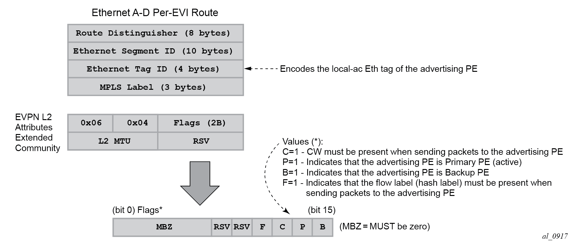
If the advertising PE has an access SAP-SDP or spoke SDP that is not part of an Ethernet Segment (ES), the PE populates the fields of the AD per-EVI route with the following values:
-
Ethernet Tag ID field is encoded with the value configured by the user in the service bgp-evpn local-attachment-circuit eth-tag value command.
-
RD and MPLS label values are encoded as specified in RFC 7432. For VXLAN, the MPLS field encodes the VXLAN VNI.
-
ESI is 0.
-
The route is sent along an EVPN L2 attributes extended community, as specified in RFC 8214, where:
-
type and subtype are 0x06 and 0x04 as allocated by IANA
-
flag C is set if a control word is configured in the service; C is always zero for VXLAN tunnels
-
P and B flags are zero
-
L2 MTU is encoded with a service MTU configured in the Epipe service
-
If the advertising PE has an access SAP-SDP or spoke SDP that is part of an ES, the AD per-EVI route is sent with the information described above, with the following minor differences:
-
The ESI encodes the corresponding non-zero value.
-
The P and B flags are set in the following cases:
-
All-active multihoming
-
All PEs that are part of the ES always set the P flag.
-
The B flag is never set in the all-active multihoming ES case.
-
-
Single-active multihoming
-
Only the DF PE sets the P bit for an EVI and the remaining PEs send it as P=0.
-
Only the backup DF PE sets the B bit.
If more than two PEs are present in the same single-active ES, the backup PE is the winner of a second DF election (excluding the DF). The remaining non-DF PEs send B=0.
-
-
Also, ES and AD per-ES routes are advertised and processed for the Ethernet-Segment, as described in RFC 7432 ESs. The ESI label sent with the AD per-ES route is used by BUM traffic on VPLS services; it is not used for Epipe traffic.
EVPN-VPWS for VXLAN tunnels in Epipe services
BGP-EVPN can be enabled in Epipe services with either SAPs or spoke SDPs at the access, as shown in EVPN-MPLS VPWS.
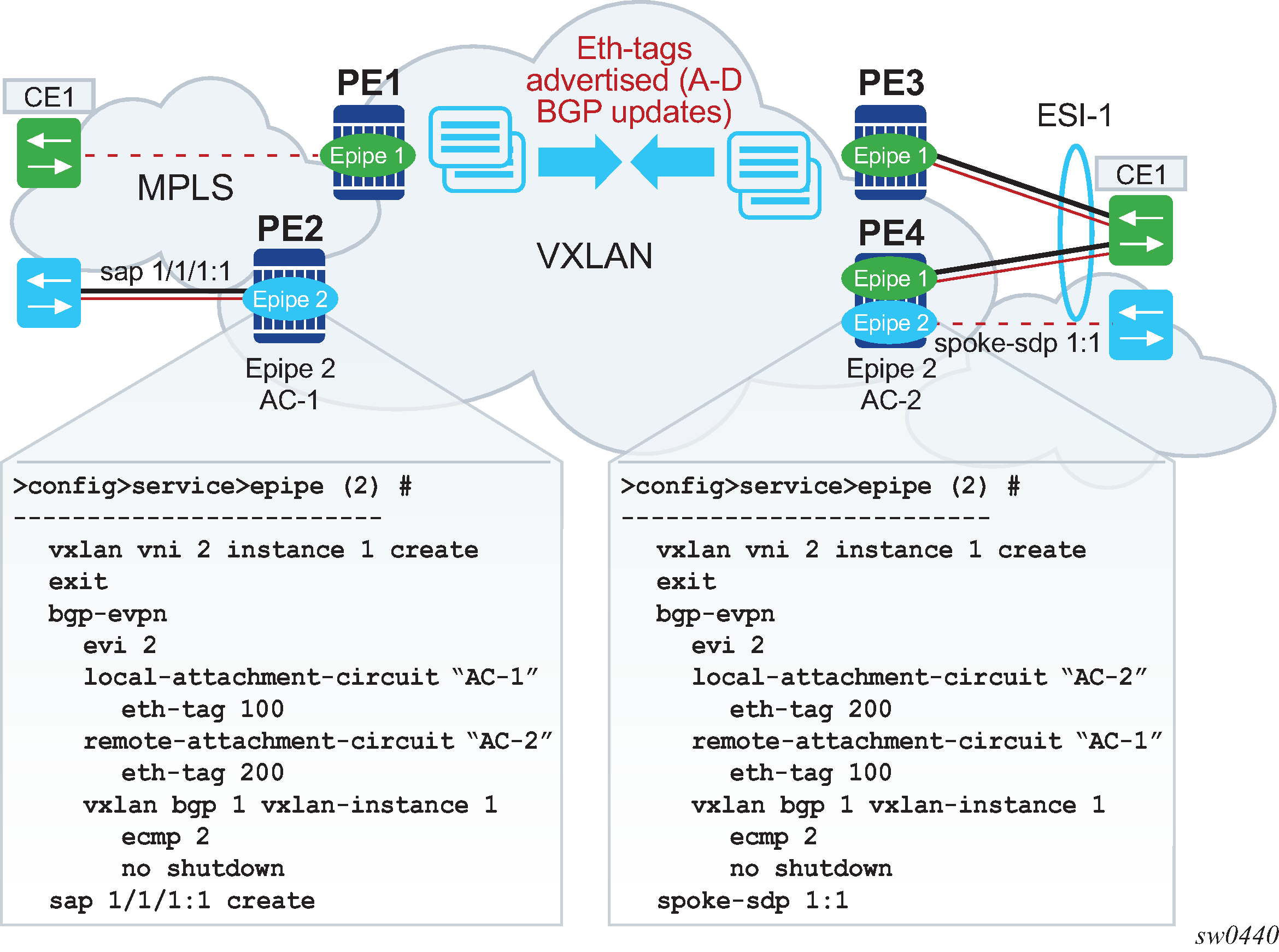
EVPN-VPWS is supported in VXLAN networks that also run EVPN-VXLAN in VPLS services. From a control plane perspective, EVPN-VPWS is a simplified point-to-point version of RFC 7432 for E-Line services for the following reasons:
-
EVPN-VPWS does not use inclusive multicast, MAC/IP routes or IP-prefix routes.
-
AD Ethernet per-EVI routes are used to advertise the local attachment circuit identifiers at each side of the VPWS instance. The attachment circuit identifiers are configured as local and remote Ethernet tags. When an AD per-EVI route is imported and the Ethernet tag matches the configured remote Ethernet tag, an EVPN destination is created for the Epipe.
In the following configuration example, Epipe 2 is an EVPN-VPWS service between PE2 and PE4 (as shown in EVPN-MPLS VPWS).
PE2>config>service>epipe(2)#
-----------------------
vxlan vni 2 instance 1 create
exit
bgp
exit
bgp-evpn
  evi 2
  local-attachment-circuit "AC-1"
    eth-tag 100
  remote-attachment-circuit "AC-2"
    eth-tag 200
  vxlan bgp 1 vxlan-instance 1
    ecmp 2
    no shutdown
sap 1/1/1:1 create
PE4>config>service>epipe(2)#
-----------------------
vxlan vni 2 instance 1 create
exit
bgp
exit
bgp-evpn
  evi 2
  local-attachment-circuit "AC-2"
    eth-tag 200
  remote-attachment-circuit "AC-1"
    eth-tag 100
  vxlan bgp 1 vxlan-instance 1
    ecmp 2
    no shutdown
spoke-sdp 1:1
The following considerations apply to the preceding example configuration:
-
When the EVI value is lower than 65535, the EVI is used to automatically derive the route-target or route-distinguisher of the service. For EVI values greater than 65535, the route-distinguisher is not automatically derived and the route-target is automatically derived, if evi-three-byte-auto-rt is configured. The EVI values must be unique in the system regardless of the type of service to which they are assigned (Epipe or VPLS).
-
Support for the following BGP-EVPN commands in Epipe services is the same as in VPLS services:
-
vxlan bgp 1 vxlan-instance 1
-
vxlan send-tunnel-encap
-
vxlan shutdown
-
vxlan ecmp
-
-
The following BGP-EVPN commands identify the local and remote attachment circuits, with the configured Ethernet tags encoded in the advertised and received AD Ethernet per-EVI routes:
-
local-attachment-circuit name
-
local-attachment-circuit name eth-tag tag-value; where tag-value is 1 to 16777215
-
remote-attachment-circuit name
-
remote-attachment-circuit name eth-tag tag-value; where tag-value is 1 to 16777215
Changes to remote Ethernet tags are allowed without shutting down BGP-EVPN VXLAN or the Epipe service. The local AC Ethernet tag value cannot be changed without BGP-EVPN VXLAN shutdown.
Both local and remote Ethernet tags are mandatory to bring up the Epipe service.
-
EVPN-VPWS Epipes can also be configured with the following characteristics:
-
Access attachment circuits can be SAPs or spoke SDP. Only manually-configured spoke SDP is supported; BGP-VPWS and endpoints are not supported. The VC switching configuration is not supported on BGP-EVPN enabled pipes.
-
EVPN-VPWS Epipes can advertise the Layer 2 (service) MTU and check its consistency as follows:
-
The advertised MTU value is taken from the configured service MTU in the Epipe service.
-
The received L2 MTU is compared to the local value. In case of a mismatch between the received MTU and the configured service MTU, the system does not set up the EVPN destination; as a result, the service does not come up.
Consider the following:
-
The system does not check the network port MTU value.
-
If the received L2 MTU value is 0, the MTU is ignored.
-
-
Using A/S PW and MC-LAG with EVPN-VPWS Epipes
The use of A/S PW (for access spoke SDP) and MC-LAG (for access SAPs) provides an alternative redundant solution for EVPN-VPWS that do not use the EVPN multi homing procedures described in RFC 8214. A/S PW and MC-LAG support on EVPN-VPWS shows the use of both mechanisms in a single Epipe.
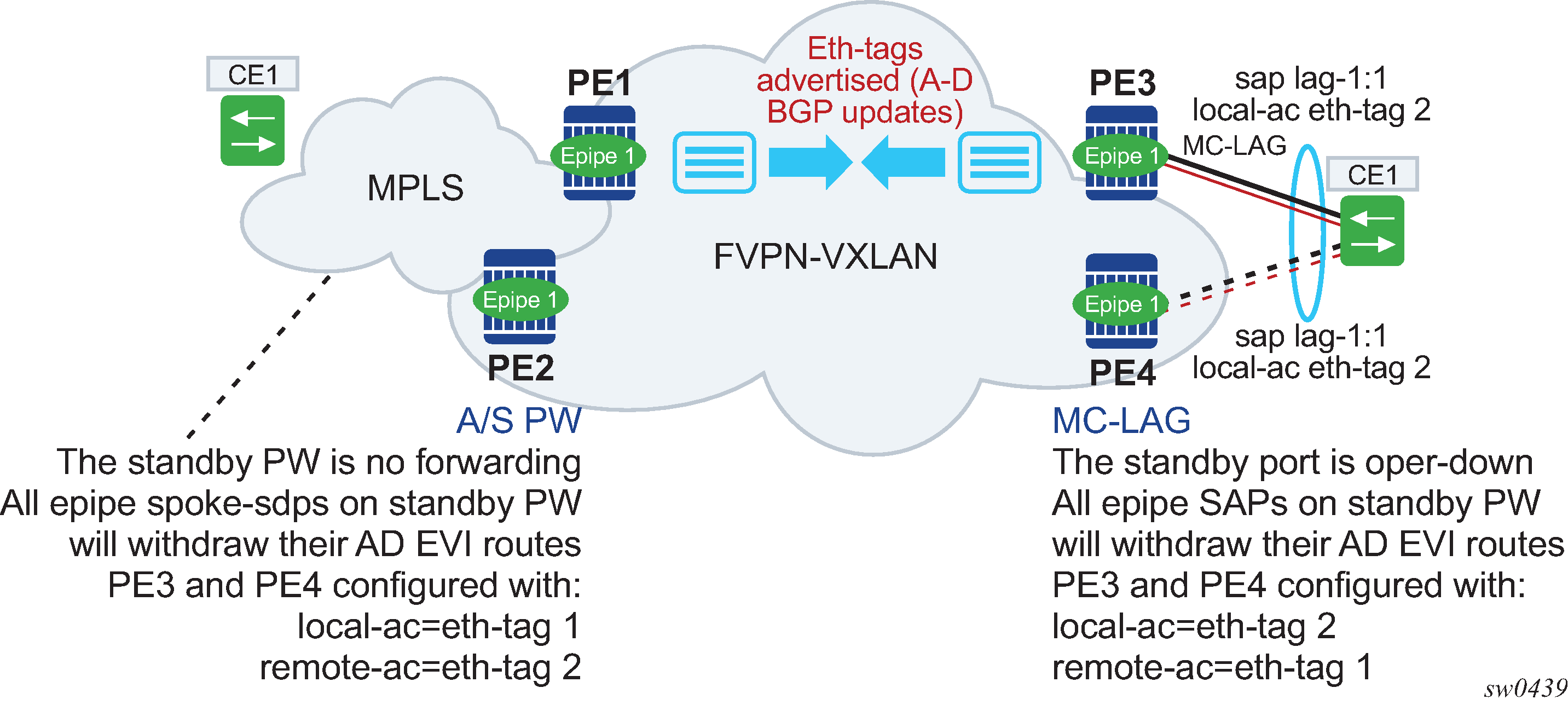
In A/S PW and MC-LAG support on EVPN-VPWS, an A/S PW connects the CE to PE1 and PE2 (left side of the diagram), and an MC-LAG connects the CE to PE3 and PE4 (right side of the diagram). As EVPN multi homing is not used, there are no AD per-ES routes or ES routes. The redundancy is handled as follows:
-
PE1 and PE2 are configured with Epipe-1, where a spoke SDP connects the service in each PE to the access CE. The local AC Ethernet tag is 1 and the remote AC Ethernet tag is 2 (in PE1/PE2).
-
PE3 and PE4 are configured with Epipe-1, where each PE has a lag SAP that belongs to a previously-configured MC-LAG construct. The local AC Ethernet tag is 2 and the remote AC Ethernet tag is 1.
-
An endpoint and A/S PW is configured on the CE on the left side of the diagram. PE1/PE2 are able to advertise Ethernet tag 1 based on the operating status or the forwarding status of the spoke SDP.
For example, if PE1 receives a standby PW status indication from the CE and the previous status was forward, it withdraws the AD EVI route for Ethernet tag 1. If PE2 receives a forward PW status indication and the previous status was standby or down, it advertises the AD EVI route for Ethernet tag 1.
-
The user can configure MC-LAG for access SAPs using the example configuration of PE3 and PE4, as shown in A/S PW and MC-LAG support on EVPN-VPWS. In this case, the MC-LAG determines which chassis is active and which is standby.
If PE4 becomes the standby chassis, the entire LAG port is brought down. As a result, the SAP goes operationally down and PE4 withdraws any previous AD EVI routes for Ethernet tag 2.
If PE3 becomes the active chassis, the LAG port becomes operationally up. As a result, the SAP and the PE3 advertise the AD per-EVI route for Ethernet tag 2.
EVPN multihoming for EVPN-VPWS services
EVPN multihoming is supported for EVPN-VPWS Epipe services with the following considerations:
-
Single-active and all-active multihoming is supported for SAPs and spoke SDP.
-
ESs can be shared between the Epipe (MPLS and VXLAN) and VPLS (MPLS) services for LAGs, ports, and SDPs.
-
No split-horizon function is required because no traffic exists between the Designated Forwarder (DF) and the non-DF for Epipe services. As a result, the ESI label is never used, and the following commands do not affect Epipe services. Additionally, configure the single-active-no-esi-label or all-active-no-esi-label modes to increase the scale of Ethernet Segments for EVPN VPWS services.
- MD-CLI
configure service system bgp evpn ethernet-segment multi-homing-mode single-active-no-esi-label configure service system bgp evpn ethernet-segment multi-homing-mode all-active-no-esi-label configure service system bgp evpn ethernet-segment pbb source-bmac-lsb - classic
CLI
configure service system bgp-evpn ethernet-segment multi-homing single-active no-esi-label
configure service system bgp-evpn ethernet-segment multi-homing all-active no-esi-label
configure service system bgp-evpn ethernet-segment source-bmac-lsb
- MD-CLI
-
The local Ethernet tag values must match on all PEs that are part of the same ES, regardless of the multi homing mode. The PEs in the ES use the AD per-EVI routes from the peer PEs to validate the PEs as DF election candidates for a specific EVI.
The DF election for Epipes that is defined in an all-active multi homing ES is not relevant because all PEs in the ES behave in the same way as follows:
-
All PEs send P=1 on the AD per-EVI routes.
-
All PEs can send upstream and downstream traffic, regardless of whether the traffic is unicast, multicast, or broadcast (all traffic is treated as unicast in the Epipe services).
Therefore, the following tools command shows N/A when all-active multihoming is configured.
*A:PE-2# tools dump service system bgp-evpn ethernet-segment "ESI-12" evi 6000 df
[03/18/2016 20:31:35] All Active VPWS - DF N/A
Aliasing is supported for traffic sent to an ES destination. If ECMP is enabled on the ingress PE, per-flow load balancing is performed to all PEs that advertise P=1. The PEs that advertise P=0, are not considered as next hops for an ES destination.
Although DF election is not relevant for Epipes in an all-active multi homing ES, it is essential for the following forwarding and backup functions in a single-active multihoming ES:
-
The PE elected as DF is the primary PE for the ES in the Epipe. The primary PE unblocks the SAP or spoke SDP for upstream and downstream traffic; the remaining PEs in the ES bring their ES SAPs or spoke SDPs operationally down.
-
The DF candidate list is built from the PEs sending ES routes for the same ES and is pruned for a specific service, depending on the availability of the AD per-ES and per-EVI routes.
-
When the SAP or spoke SDPs that are part of the ES come up, the AD per-EVI routes are sent with P=0 and B=0. The remote PEs do not start sending traffic until the DF election process is complete and the ES activation timer is expired, and the PEs advertise AD per-EVI routes with P and B bits other than zero.
-
The backup PE function is supported as defined in RFC 8214. The primary PE, backup, or none status is signaled by the PEs (part of the same single-active MH ES) in the P or B flags of the EVPN L2 attributes extended community. EVPN-VPWS single-active multihoming shows the advertisement and use of the primary, backup, or none indication by the PEs in the ES.
Figure 13. EVPN-VPWS single-active multihoming 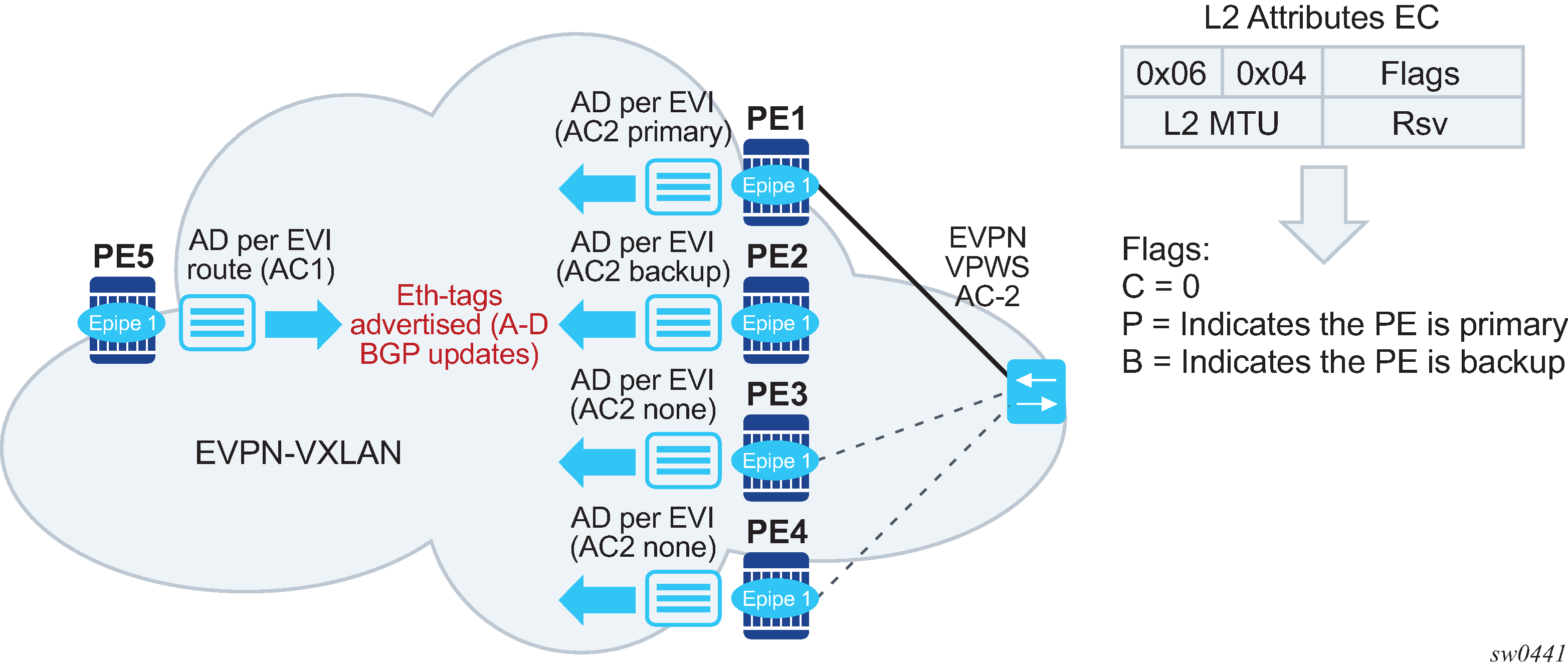
As specified in RFC 7432, the remote PEs in VPLS services have knowledge of the primary PE in the remote single-active ES, based on the advertisement of the MAC/IP routes because only the DF learns and advertises MAC/IP routes.
Because there are no MAC/IP routes in EVPN-VPWS, the remote PEs can forward the traffic based on the P/B bits. The process is described in the following list:
-
The DF PE for an EVI (PE1) sends P=1 and B=0.
-
For each ES or EVI, a second DF election is run among the PEs in the backup candidate list to elect the backup PE. The backup PE sends P=0 and B=1 (PE2).
-
All remaining multi homing PEs send P=0 and B=0 (PE3 and PE4).
-
At the remote PEs (PE5), the P and B flags are used to identify the primary and backup PEs within the ES destination. The traffic is then sent to the primary PE, provided that it is active.
-
-
When a remote PE receives the withdrawal of an Ethernet AD per-ES (or per-EVI) route from the primary PE, the remote PE immediately switches the traffic to the backup PE for the affected EVIs. The backup PE takes over immediately without waiting for the ES activation timer to bring up its SAP or spoke SDP.
-
The BGP-EVPN MPLS ECMP setting also governs the forwarding in single-active multi homing, regardless of the single-active multi homing bit in the AD per-ES route received at the remote PE (PE5).
-
PE5 always sends the traffic to the primary remote PE (the owner of the P=1 bit). In case of multiple primary PEs and ECMP>1, PE5 load balances the traffic to all primary PEs, regardless of the multi homing mode.
-
If the last primary PE withdraws its AD per-EVI or per-ES route, PE5 sends the traffic to the backup PE or PEs. In case of multiple backup PEs and ECMP>1, PE1 load balances the traffic to the backup PEs.
-
Non-system IPv4/IPv6 VXLAN termination for EVPN-VPWS services
EVPN-VPWS services support non-system IPv4/IPv6 VXLAN termination. For system configuration information, see Non-system IPv4 and IPv6 VXLAN termination in VPLS, R-VPLS, and Epipe services.
EVPN multihoming is supported when the PEs use non-system IP termination, however additional configuration steps are needed in this case:
-
The configure service system bgp-evpn eth-seg es-orig-ip ip-address command must be configured with the non-system IPv4/IPv6 address used for the EVPN-VPWS VXLAN service. As a result, this command modifies the originating-ip field in the ES routes advertised for the Ethernet Segment, and makes the system use this IP address when adding the local PE as DF candidate.
-
The configure service system bgp-evpn eth-seg route-next-hop ip-address command must be configured with the non-system IP address, too. The command changes the next-hop of the ES and AD per-ES routes to the configured address.
-
The non-system IP address (in each of the PEs in the ES) must match in these three commands for the local PE to be considered suitable for DF election:
-
es-orig-ip ip-address
-
route-next-hop ip-address
-
vxlan-src-vtep ip-address
-
EVPN for VXLAN in IRB backhaul R-VPLS services and IP prefixes
Gateway IRB on the DC PE for an L3 EVPN/VXLAN DC shows a Layer 3 DC model, where a VPRN is defined in the DGWs, connecting the tenant to the WAN. That VPRN instance is connected to the VPRNs in the NVEs by means of an IRB backhaul R-VPLS. Because the IRB backhaul R-VPLS provides connectivity only to all the IRB interfaces and the DGW VPRN is not directly connected to all the tenant subnets, the WAN ip-prefixes in the VPRN routing table must be advertised in EVPN. In the same way, the NVEs send IP prefixes in EVPN that is received by the DGW and imported in the VPRN routing table.
Local router interface host addresses are not advertised in EVPN by default. To advertise them, the ip-route-advertisement incl-host command must be enabled. For example:
===============================================================================
Route Table (Service: 2)
===============================================================================
Dest Prefix[Flags]                            Type    Proto     Age        Pref
      Next Hop[Interface Name]                         Active     Metric
-------------------------------------------------------------------------------
10.1.1.0/24                                   Local   Local     00h00m11s  0
       if                                              Y            0
10.1.1.100/32                                 Local   Host      00h00m11s  0
       if                                              Y            0
==============================================================================
For the case displayed by the output above, the behavior is the following:
ip-route-advertisement only local subnet (default) - 10.1.1.0/24 is advertised
ip-route-advertisement incl-host local subnet, host - 10.1.1.0/24 and 10.1.1.100/32 are advertised
Below is an example of VPRN (500) with two IRB interfaces connected to backhaul R-VPLS services 501 and 502 where EVPN-VXLAN runs:
vprn 500 customer 1 create
            ecmp 4
            route-distinguisher 65072:500
            vrf-target target:65000:500
            interface "evi-502" create
                address 10.20.20.72/24
                vpls "evpn-vxlan-502"
                exit
            exit
            interface "evi-501" create
                address 10.10.10.72/24
                vpls "evpn-vxlan-501"
                exit
            exit
            no shutdown
vpls 501 name "evpn-vxlan-501" customer 1 create
            allow-ip-int-bind
            vxlan instance 1 vni 501 create
            exit
            bgp
                route-distinguisher 65072:501
                route-target export target:65000:501 import target:65000:501
            exit
            bgp-evpn
                ip-route-advertisement incl-host
                vxlan bgp 1 vxlan-instance 1
                    no shutdown
                exit
            exit
            no shutdown
        exit
vpls 502 name "evpn-vxlan-502" customer 1 create
            allow-ip-int-bind
            vxlan instance 1 vni 502 create
            exit
            bgp
                route-distinguisher 65072:502
                route-target export target:65000:502 import target:65000:502
            exit
            bgp-evpn
                ip-route-advertisement incl-host
                vxlan bgp 1 vxlan-instance 1
                    no shutdown
                exit
            exit
            no shutdown
        exit
When the above commands are enabled, the router behaves as follows:
Receive route-type 5 routes and import the IP prefixes and associated IP next-hops into the VPRN routing table.
If the route-type 5 is successfully imported by the router, the prefix included in the route-type 5 (for example, 10.0.0.0/24), is added to the VPRN routing table with a next-hop equal to the gateway IP included in the route (for example, 192.0.0.1. that refers to the IRB IP address of the remote VPRN behind which the IP prefix sits).
When the router receives a packet from the WAN to the 10.0.0.0/24 subnet, the IP lookup on the VPRN routing table yields 192.0.0.1 as the next-hop. That next-hop is resolved to a MAC in the ARP table and the MAC resolved to a VXLAN tunnel in the FDB table
Note: IRB MAC and IP addresses are advertised in the IRB backhaul R-VPLS in routes type 2.
Generate route-type 5 routes for the IP prefixes in the associated VPRN routing table.
For example, if VPRN-1 is attached to EVPN R-VPLS 1 and EVPN R-VPLS 2, and R-VPLS 2 has bgp-evpn ip-route-advertisement configured, the router advertises the R-VPLS 1 interface subnet in one route-type 5.
Routing policies can filter the imported and exported IP prefix routes accordingly.
The VPRN routing table can receive routes from all the supported protocols (BGP-VPN, OSPF, IS-IS, RIP, static routing) as well as from IP prefixes from EVPN, as shown below:
*A:PE72# show router 500 route-table
===============================================================================
Route Table (Service: 500)
===============================================================================
Dest Prefix[Flags]                            Type    Proto     Age        Pref
      Next Hop[Interface Name]                                    Metric
-------------------------------------------------------------------------------
10.20.20.0/24                                 Local   Local     01d11h10m  0
       evi-502                                                      0
10.20.20.71/32                                Remote  BGP EVPN  00h02m26s  169
       10.10.10.71                                                  0
10.10.10.0/24                                Remote  Static    00h00m05s  5
       10.10.10.71                                                  1
10.16.0.1/32                                 Remote  BGP EVPN  00h02m26s  169
       10.10.10.71                                                  0
-------------------------------------------------------------------------------
No. of Routes: 4
The following considerations apply:
The route Preference for EVPN IP prefixes is 169.
BGP IP-VPN routes have a preference of 170 by default, therefore, if the same route is received from the WAN over BGP-VPRN and from BGP-EVPN, then the EVPN route is preferred.
When the same route-type 5 prefix is received from different gateway IPs, ECMP is supported if configured in the VPRN.
All routes in the VPRN routing table (as long as they do not point back to the EVPN R-VPLS interface) are advertised via EVPN.
Although the description above is focused on IPv4 interfaces and prefixes, it applies to IPv6 interfaces too. The following considerations are specific to IPv6 VPRN R-VPLS interfaces:
IPv4 and IPv6 interfaces can be defined on R-VPLS IP interfaces at the same time (dual-stack).
The user may configure specific IPv6 Global Addresses on the VPRN R-VPLS interfaces. If a specific Global IPv6 Address is not configured on the interface, the Link Local Address interface MAC/IP is advertised in a route type 2 as soon as IPv6 is enabled on the VPRN R-VPLS interface.
Routes type 5 for IPv6 prefixes are advertised using either the configured Global Address or the implicit Link Local Address (if no Global Address is configured).
If more than one Global Address is configured, normally the first IPv6 address is used as gateway IP. The ‟first IPv6 address” refers to the first one on the list of IPv6 addresses shown through the show router <id> interface interface IPv6 or through SNMP.
The rest of the addresses are advertised only in MAC-IP routes (Route Type 2) but not used as gateway IP for IPv6 prefix routes.
EVPN for VXLAN in EVPN tunnel R-VPLS services
EVPN-tunnel gateway IRB on the DC PE for a Layer 3 EVPN/VXLAN DC shows an L3 connectivity model that optimizes the solution described in EVPN for VXLAN in IRB backhaul R-VPLS services and IP prefixes. Instead of regular IRB backhaul R-VPLS services for the connectivity of all the VPRN IRB interfaces, EVPN tunnels can be configured. The main advantage of using EVPN tunnels is that they do not need the configuration of IP addresses, as regular IRB R-VPLS interfaces do.
In addition to the ip-route-advertisement command, this model requires the configuration of the config>service>vprn>if>vpls <name> evpn-tunnel.
The example below shows a VPRN (500) with an EVPN-tunnel R-VPLS (504):
vprn 500 customer 1 create
            ecmp 4
            route-distinguisher 65071:500
            vrf-target target:65000:500
            interface "evi-504" create
                vpls "evpn-vxlan-504"
                    evpn-tunnel
                exit
            exit
            no shutdown
        exit
        vpls 504 name ‟evpn-vxlan-504” customer 1 create
            allow-ip-int-bind
            vxlan instance 1 vni 504 create
            exit
            bgp
                route-distinguisher 65071:504
                route-target export target:65000:504 import target:65000:504
            exit
            bgp-evpn
                ip-route-advertisement
                vxlan bgp 1 vxlan-instance 1
                    no shutdown
                exit
            exit
            no shutdown
        exit
A specified VPRN supports regular IRB backhaul R-VPLS services as well as EVPN tunnel R-VPLS services.
The process followed upon receiving a route-type 5 on a regular IRB R-VPLS interface differs from the one for an EVPN-tunnel type:
IRB backhaul R-VPLS VPRN interface:
When a route-type 2 that includes an IP prefix is received and it becomes active, the MAC/IP information is added to the FDB and ARP tables. This can be checked with the show router arp command and the show service id fdb detail command.
When route-type 5 is received and becomes active for the R-VPLS service, the IP prefix is added to the VPRN routing table, regardless of the existence of a route-type 2 that can resolve the gateway IP address. If a packet is received from the WAN side and the IP lookup hits an entry for which the gateway IP (IP next-hop) does not have an active ARP entry, the system uses ARP to get a MAC. If ARP is resolved but the MAC is unknown in the FDB table, the system floods into the TLS multicast list. Routes type 5 can be checked in the routing table with the show router route-table and show router fib commands.
EVPN tunnel R-VPLS VPRN interface:
When route-type 2 is received and becomes active, the MAC address is added to the FDB (only).
When a route-type 5 is received and active, the IP prefix is added to the VPRN routing table with next-hop equal to EVPN tunnel: GW-MAC.
For example, ET-d8:45:ff:00:01:35, where the GW-MAC is added from the GW-MAC extended community sent along with the route-type 5.
If a packet is received from the WAN side, and the IP lookup hits an entry for which the next-hop is a EVPN tunnel: GW-MAC, the system looks up the GW-MAC in the FDB. Usually a route-type 2 with the GW-MAC is previously received so that the GW-MAC can be added to the FDB. If the GW-MAC is not present in the FDB, the packet is dropped.
IP prefixes with GW-MACs as next-hops are displayed by the show router command, as shown below:
*A:PE71# show router 500 route-table
===============================================================================
Route Table (Service: 500)
===============================================================================
Dest Prefix[Flags]                            Type    Proto     Age        Pref
      Next Hop[Interface Name]                                    Metric
-------------------------------------------------------------------------------
10.20.20.72/32                                Remote  BGP EVPN  00h23m50s  169
       10.10.10.72                                                  0
10.30.30.0/24                                 Remote  BGP EVPN  01d11h30m  169
       evi-504 (ET-d8:45:ff:00:01:35)                               0
10.10.10.0/24                                Remote  BGP VPN   00h20m52s  170
       192.0.2.69 (tunneled)                                        0
10.1.0.0/16                                  Remote  BGP EVPN  00h22m33s  169
       evi-504 (ET-d8:45:ff:00:01:35)                               0
-------------------------------------------------------------------------------
No. of Routes: 4
The GW-MAC as well as the rest of the IP prefix BGP attributes are displayed by the show router bgp routes evpn ip-prefix command.
*A:Dut-A# show router bgp routes evpn ip-prefix prefix 3.0.1.6/32 detail
===============================================================================
BGP Router ID:10.20.1.1        AS:100         Local AS:100
===============================================================================
Legend -
Status codes  : u - used, s - suppressed, h - history, d - decayed, * - valid
Origin codes  : i - IGP, e - EGP, ? - incomplete, > - best, b - backup

===============================================================================
BGP EVPN IP-Prefix Routes
===============================================================================
-------------------------------------------------------------------------------
Original Attributes

Network        : N/A
Nexthop        : 10.20.1.2
From           : 10.20.1.2
Res. Nexthop   : 192.168.19.1
Local Pref.    : 100                    Interface Name : NotAvailable
Aggregator AS  : None                   Aggregator     : None
Atomic Aggr.   : Not Atomic             MED            : 0
AIGP Metric    : None
Connector      : None
Community      : target:100:1 mac-nh:00:00:01:00:01:02
                 bgp-tunnel-encap:VXLAN
Cluster        : No Cluster Members
Originator Id  : None                   Peer Router Id : 10.20.1.2
Flags          : Used  Valid  Best  IGP
Route Source   : Internal
AS-Path        : No As-Path
EVPN type      : IP-PREFIX
ESI            : N/A                    Tag            : 1
Gateway Address: 00:00:01:00:01:02
Prefix         : 3.0.1.6/32             Route Dist.    : 10.20.1.2:1
MPLS Label    : 262140
Route Tag      : 0xb
Neighbor-AS    : N/A
Orig Validation: N/A
Source Class   : 0                      Dest Class     : 0

Modified Attributes

Network        : N/A
Nexthop        : 10.20.1.2
From           : 10.20.1.2
Res. Nexthop   : 192.168.19.1
Local Pref.    : 100                    Interface Name : NotAvailable
Aggregator AS  : None                   Aggregator     : None
Atomic Aggr.   : Not Atomic             MED            : 0
AIGP Metric    : None
Connector      : None
Community      : target:100:1 mac-nh:00:00:01:00:01:02
                 bgp-tunnel-encap:VXLAN
Cluster        : No Cluster Members
Originator Id  : None                   Peer Router Id : 10.20.1.2
Flags          : Used  Valid  Best  IGP
Route Source   : Internal
AS-Path        : 111
EVPN type      : IP-PREFIX
ESI            : N/A                    Tag            : 1
Gateway Address: 00:00:01:00:01:02
Prefix         : 3.0.1.6/32             Route Dist.    : 10.20.1.2:1
MPLS Label    : 262140
Route Tag      : 0xb
Neighbor-AS    : 111
Orig Validation: N/A
Source Class   : 0                      Dest Class     : 0

-------------------------------------------------------------------------------
Routes : 1
===============================================================================
EVPN tunneling is also supported on IPv6 VPRN interfaces. When sending IPv6 prefixes from IPv6 interfaces, the GW-MAC in the route type 5 (IP-prefix route) is always zero. If no specific Global Address is configured on the IPv6 interface, the routes type 5 for IPv6 prefixes are always sent using the Link Local Address as GW-IP. The following example output shows an IPv6 prefix received through BGP EVPN.
*A:PE71# show router 30 route-table ipv6

===============================================================================
IPv6 Route Table (Service: 30)
===============================================================================
Dest Prefix[Flags]                            Type    Proto     Age        Pref
      Next Hop[Interface Name]                                    Metric
-------------------------------------------------------------------------------
2001:db8:1000::/64                            Local   Local     00h01m19s  0
       int-PE-71-CE-1                                               0
2001:db8:2000::1/128                          Remote  BGP EVPN  00h01m20s  169
       fe80::da45:ffff:fe00:6a-"int-evi-301"                        0
-------------------------------------------------------------------------------
No. of Routes: 2
Flags: n = Number of times nexthop is repeated
       B = BGP backup route available
       L = LFA nexthop available
       S = Sticky ECMP requested
===============================================================================

*A:PE71# show router bgp routes evpn ipv6-prefix prefix 2001:db8:2000::1/128 hunt
===============================================================================
 BGP Router ID:192.0.2.71       AS:64500       Local AS:64500
===============================================================================
 Legend -
 Status codes  : u - used, s - suppressed, h - history, d - decayed, * - valid
                 l - leaked
 Origin codes  : i - IGP, e - EGP, ? - incomplete, > - best, b - backup

===============================================================================
BGP EVPN IP-Prefix Routes
===============================================================================
-------------------------------------------------------------------------------
RIB In Entries
-------------------------------------------------------------------------------
Network        : N/A
Nexthop        : 192.0.2.69
From           : 192.0.2.69
Res. Nexthop   : 192.168.19.2
Local Pref.    : 100                    Interface Name : int-71-69
Aggregator AS  : None                   Aggregator     : None
Atomic Aggr.   : Not Atomic             MED            : 0
AIGP Metric    : None
Connector      : None
Community      : target:64500:301 bgp-tunnel-encap:VXLAN
Cluster        : No Cluster Members
Originator Id  : None                   Peer Router Id : 192.0.2.69
Flags          : Used  Valid  Best  IGP
Route Source   : Internal
AS-Path        : No As-Path
EVPN type      : IP-PREFIX
ESI            : N/A                    Tag            : 301
Gateway Address: fe80::da45:ffff:fe00:*
Prefix         : 2001:db8:2000::1/128   Route Dist.    : 192.0.2.69:301
MPLS Label     : 0
Route Tag      : 0
Neighbor-AS    : N/A
Orig Validation: N/A
Source Class   : 0                      Dest Class     : 0
Add Paths Send : Default
Last Modified  : 00h41m17s

-------------------------------------------------------------------------------
RIB Out Entries
-------------------------------------------------------------------------------
-------------------------------------------------------------------------------
Routes : 1
===============================================================================
Layer 2 multicast optimization for VXLAN (Assisted-Replication)
The Assisted-Replication feature for IPv4 VXLAN tunnels (both Leaf and Replicator functions) is supported in compliance with the non-selective mode described in IETF Draft draft-ietf-bess-evpn-optimized-ir.
The Assisted-Replication feature is a Layer 2 multicast optimization feature that helps software-based PE and NVEs with low-performance replication capabilities to deliver broadcast and multicast Layer 2 traffic to remote VTEPs in the VPLS service.
The EVPN and proxy-ARP/ND capabilities can reduce the amount of broadcast and unknown unicast in the VPLS service; ingress replication is sufficient for most use cases in this scenario. However, when multicast applications require a significant amount of replication at the ingress node, software-based nodes struggle because of their limited replication performance. By enabling the Assisted-Replication Leaf function, all the broadcast and multicast packets are sent to a SR OS router configured as a Replicator, which replicates the traffic to all the VTEPs in the VPLS service on behalf of the Leaf. This guarantees that the broadcast or multicast traffic is delivered to all the VPLS participants without any packet loss caused by performance issues.
The Leaf or Replicator function is enabled per VPLS service by the configure service vpls vxlan assisted-replication {replicator | leaf} command. In addition, the Replicator requires the configuration of an Assisted-Replication IP (AR-IP) address. The AR-IP loopback address indicates whether the received VXLAN packets have to be replicated to the remote VTEPs. The AR-IP address is configured using the configure service system vxlan assisted-replication-ip <ip-address> command.
Based on the assisted-replication {replicator | leaf} configuration, the 7705 SAR Gen 2 can behave as a Replicator (AR-R), Leaf (AR-L), or Regular Network Virtualization Edge (RNVE) router. An RNVE router does not support the Assisted-Replication feature. Because it is configured with no assisted replication, the RNVE router ignores the AR-R and AR-L information and replicates to its flooding list where VTEPs are added based on the regular ingress replication routes.
Replicator (AR-R) procedures
An AR-R configuration is shown in the following example.
*A:PE-2>config>service>system>vxlan# info
----------------------------------------------
            assisted-replication-ip 10.2.2.2
----------------------------------------------
*A:PE-2>config>service>vpls# info
----------------------------------------------
            vxlan instance 1 vni 4000 create
                assisted-replication replicator
            exit
            bgp
            exit
            bgp-evpn
                evi 4000
                vxlan bgp 1 vxlan-instance 1
                    no shutdown
                exit
<snip>
            no shutdown
----------------------------------------------
In this example configuration, the BGP advertises a new inclusive multicast route with tunnel-type = AR, type (T) = AR-R, and tunnel-id = originating-ip = next-hop = assisted-replication-ip (IP address 10.2.2.2 in the preceding example). In addition to the AR route, the AR-R sends a regular IR route if ingress-repl-inc-mcast-advertisement is enabled.
The AR-R builds a flooding list composed of ACs (SAPs and SDP bindings) and VXLAN tunnels to remote nodes in the VPLS. All objects in the flooding list are broadcast/multicast (BM) and unknown unicast (U) capable. The following example output of the show service id vxlan command shows that the VXLAN destinations in the flooding list are tagged as ‟BUM”.
*A:PE-2# show service id 4000 vxlan
===============================================================================
Vxlan Src Vtep IP: N/A
===============================================================================
VPLS VXLAN, Ingress VXLAN Network Id: 4000
Creation Origin: manual
Assisted-Replication: replicator
RestProtSrcMacAct: none
===============================================================================
VPLS VXLAN service Network Specifics
===============================================================================
Ing Net QoS Policy : none                            Vxlan VNI Id     : 4000
Ingress FP QGrp    : (none)                          Ing FP QGrp Inst : (none)
===============================================================================
Egress VTEP, VNI
===============================================================================
VTEP Address                            Egress VNI  Num. MACs   Mcast Oper  L2
                                                                      State PBR
-------------------------------------------------------------------------------
192.0.2.3                               4000        0           BUM   Up    No
192.0.2.5                               4000        0           BUM   Up    No
192.0.2.6                               4000        0           BUM   Up    No
-------------------------------------------------------------------------------
Number of Egress VTEP, VNI : 3
-------------------------------------------------------------------------------
===============================================================================
When the AR-R receives a BUM packet on an AC, the AR-R forwards the packet to its flooding list (including the local ACs and remote VTEPs).
When the AR-R receives a BM packet on a VXLAN tunnel, it checks the IP DA of the underlay IP header and performs the following BM packet processing.
If the destination IP matches its AR-IP, the AR-R forwards the BM packet to its flooding list (ACs and VXLAN tunnels). The AR-R performs source suppression to ensure that the traffic is not sent back to the originating Leaf.
If the destination IP matches its regular VXLAN termination IP (IR-IP), the AR-R skips all the VXLAN tunnels from the flooding list and only replicates to the local ACs. This is the default Ingress Replication (IR) behavior.
Leaf (AR-L) procedures
An AR-L is configured as shown in the following example.
A:PE-3>config>service>vpls# info
----------------------------------------------
            vxlan instance 1 vni 4000 create
                assisted-replication leaf replicator-activation-time 30
            bgp
            exit
            bgp-evpn
                evi 4000
                vxlan bgp 1 vxlan-instance 1
                    no shutdown
                exit
                mpls
                    shutdown
                exit
            exit
            stp
                shutdown
            exit
            sap 1/1/1:4000 create
                no shutdown
            exit
            no shutdown
----------------------------------------------
In this example configuration, the BGP advertises a new inclusive multicast route with a tunnel-type = IR, type (T) = AR-L and tunnel-id = originating-ip = next-hop = IR-IP (IP address terminating VXLAN normally, either system-ip or vxlan-src-vtep address).
The AR-L builds a single flooding list per service but controlled by the BM and U flags. These flags are displayed in the following show service id vxlan command example output.
A:PE-3# show service id 4000 vxlan
===============================================================================
Vxlan Src Vtep IP: N/A
===============================================================================
VPLS VXLAN, Ingress VXLAN Network Id: 4000
Creation Origin: manual
Assisted-Replication: leaf      Replicator-Activation-Time: 30
RestProtSrcMacAct: none
===============================================================================
VPLS VXLAN service Network Specifics
===============================================================================
Ing Net QoS Policy : none                            Vxlan VNI Id     : 4000
Ingress FP QGrp    : (none)                          Ing FP QGrp Inst : (none)
===============================================================================
Egress VTEP, VNI
===============================================================================
VTEP Address                            Egress VNI  Num. MACs   Mcast Oper  L2
                                                                      State PBR
-------------------------------------------------------------------------------
10.2.2.2                                 4000        0           BM    Up    No
10.4.4.4                                 4000        0           -     Up    No
192.0.2.2                               4000        0           U     Up    No
192.0.2.5                               4000        0           U     Up    No
192.0.2.6                               4000        0           U     Up    No
-------------------------------------------------------------------------------
Number of Egress VTEP, VNI : 5
-------------------------------------------------------------------------------
===============================================================================
The AR-L creates the following VXLAN destinations when it receives and selects a Replicator-AR route or the Regular-IR routes:
A VXLAN destination to each remote PE that sent an IR route. These bindings have the U flag set.
A VXLAN destination to the selected AR-R. These bindings have only the BM flag set; the U flag is not set.
The non-selected AR-Rs create a binding with flag ‟-” (in the CPM) that is displayed by the show service id vxlan command. Although the VXLAN destinations to non-selected AR-Rs do not carry any traffic, the destinations count against the total limit and must be considered when accounting for consumed VXLAN destinations in the router.
The BM traffic is only sent to the selected AR-R, whereas the U (unknown unicast) traffic is sent to all the destinations with the U flag.
The AR-L performs per-service load-balancing of the BM traffic when two or more AR-Rs exist in the same service. The AR Leaf creates a list of candidate PEs for each AR-R (ordered by IP and VNI; candidate 0 being the lowest IP and VNI). The replicator is selected out of a modulo function of the service-id and the number of replicators, as shown in the following example output.
A:PE-3# show service id 4000 vxlan assisted-replication replicator
===============================================================================
Vxlan AR Replicator Candidates
===============================================================================
VTEP Address           Egress VNI     In Use  In Candidate List Pending Time
-------------------------------------------------------------------------------
10.2.2.2                4000           yes     yes               0
10.4.4.4                4000           no      yes               0
-------------------------------------------------------------------------------
Number of entries : 2
-------------------------------------------------------------------------------
===============================================================================
A change in the number of Replicator-AR routes (for example, if a route is withdrawn or a new route appears) affects the result of the hashing, which may cause a different AR-R to be selected.
The following list summarizes other aspects of the AR-L behavior:
When a Leaf receives a BM packet on an AC, it sends the packet to its flood list that includes access SAP or SDP bindings and VXLAN destinations with BM or BUM flags. If a single AR-R is selected, only a VXLAN destination includes the BM flags.
Control plane-generated BM packets, such as ARP/ND (when proxy-ARP/ND is enabled) or Eth-CFM, follow the behavior of regular data plane BM packets.
When a Leaf receives an unknown unicast packet on an AC, it sends the packet to the flood-list, skipping the AR destination because the U flag is set to 0. To avoid packet re-ordering, the unknown unicast packets do not go through the AR-R.
When a Leaf receives a BUM packet on an overlay tunnel, it forwards the packet to the flood list, skipping the VXLAN tunnels (that is, the packet is sent to the local ACs and never to a VXLAN tunnel). This is the default IR behavior.
When the last Replicator-AR route is withdrawn, the AR-L removes the AR destination from the flood list and falls back to ingress replication.
AR BM replication behavior for a BM packet shows the expected replication behavior for BM traffic when received at the access on an AR-R, AR-L, or RNVE router. Unknown unicast follows regular ingress replication behavior regardless of the role of the ingress node for the specific service.
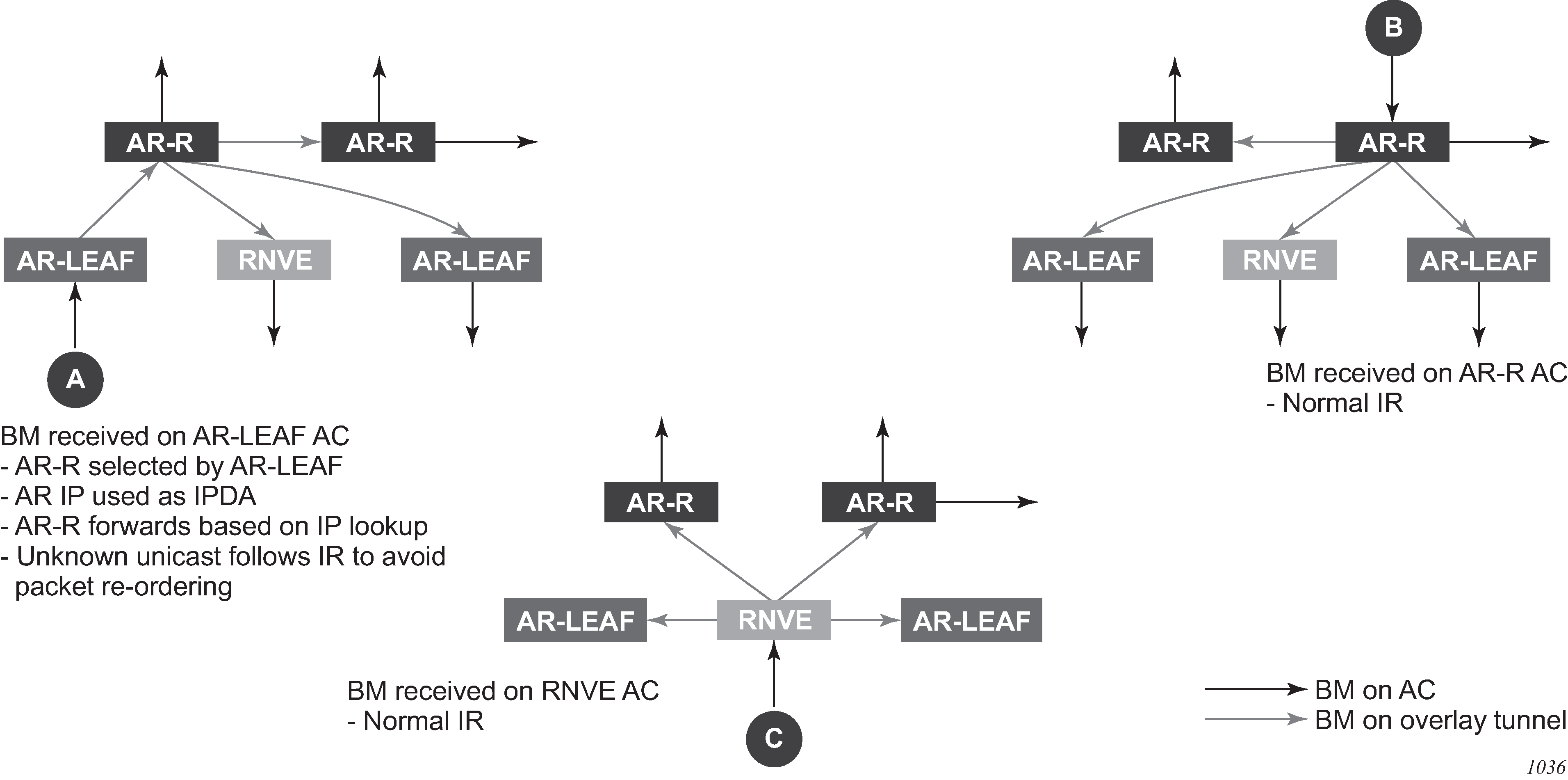
Assisted-Replication interaction with other VPLS features
The Assisted-Replication feature has the following limitations:
The following features are not supported on the same service where the Assisted-Replication feature is enabled.
Aggregate QoS per VNI
VXLAN IPv6 transport
IGMP/MLD/PIM-snooping
Assisted-Replication Leaf and Replicator functions are mutually exclusive within the same VPLS service.
The Assisted-Replication feature is supported with IPv4 non-system-ip VXLAN termination. However, the configured assisted-replication-ip (AR-IP) must be different from the tunnel termination IP address.
The AR-IP address must be a /32 loopback interface on the base router.
The Assisted-Replication feature is only supported in EVPN-VXLAN services (VPLS with BGP-EVPN vxlan enabled). Although services with a combination of EVPN-MPLS and EVPN-VXLAN are supported, the Assisted-Replication configuration is only relevant to the VXLAN.
EVPN VXLAN multihoming
SR OS supports EVPN VXLAN multihoming as specified in RFC 8365. Similar to EVPN-MPLS, as described in EVPN for MPLS tunnels, ESs and virtual ESs can be associated with VPLS and R-VPLS services where BGP-EVPN VXLAN is enabled. EVPN multihoming for EVPN-VXLAN illustrates the use of ESs in EVPN VXLAN networks.
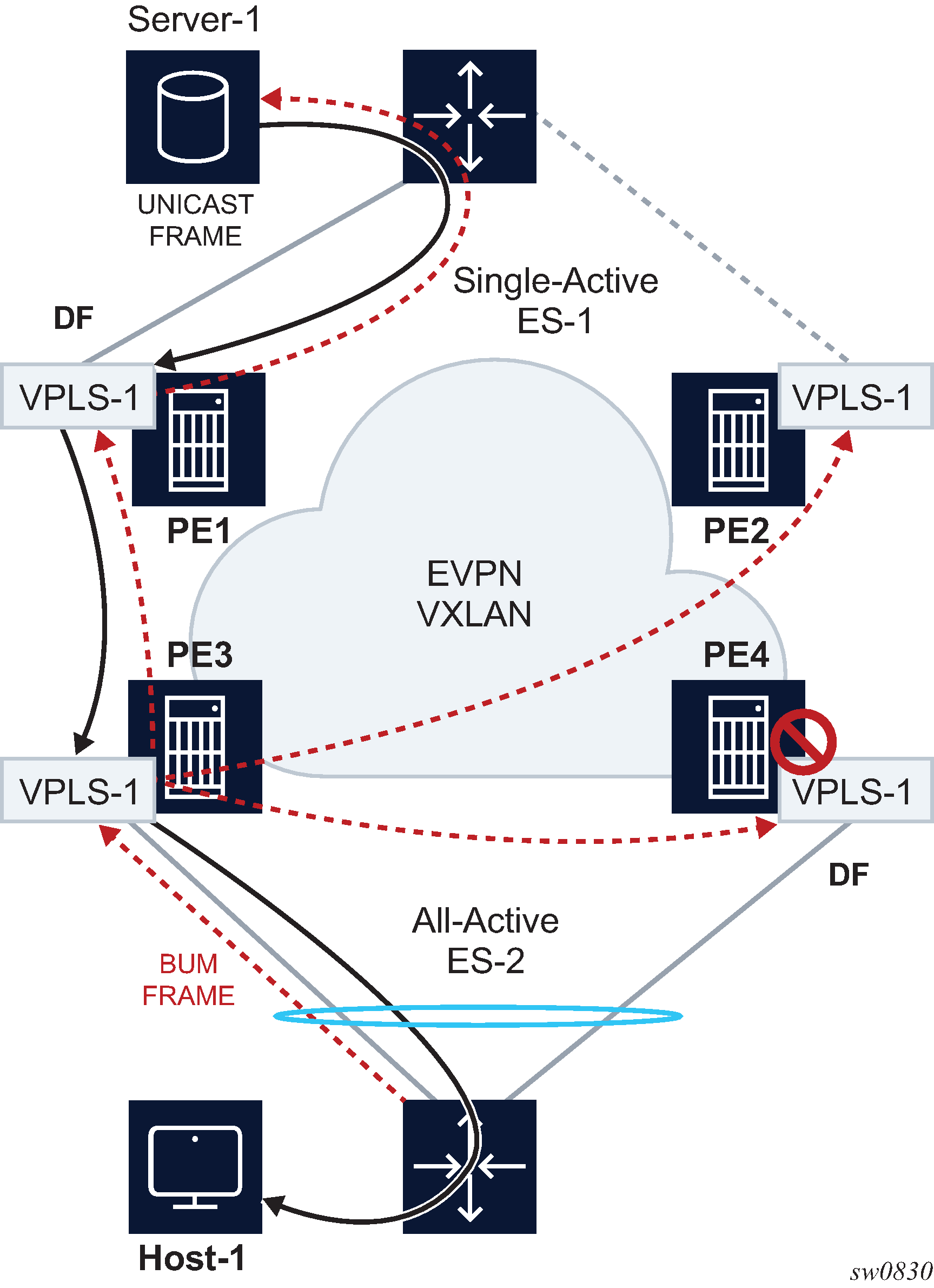
The multihoming procedures consist of three components:
Designated Forwarder (DF) election
split-horizon
aliasing
DF election is the mechanism by which the PEs attached to the same ES elect a single PE to forward all traffic (in case of single-active mode) or all BUM traffic (in case of all-active mode) to the multihomed CE. The same DF Election mechanisms described in EVPN for MPLS tunnels are supported for VXLAN services.
Split-horizon is the mechanism by which BUM traffic received from a peer ES PE is filtered so that it is not looped back to the CE that first transmitted the frame. It is applicable to all-active multihoming. This is illustrated in EVPN multihoming for EVPN-VXLAN, where PE4 receives BUM traffic from PE3 but, in spite of being the DF for ES-2, PE4 filters the traffic and does not send it back to host-1. While split-horizon filtering uses ESI-labels in EVPN MPLS services, an alternative procedure called ‟Local Bias” is applied in VXLAN services, as described in RFC 8365. In MPLS services, split-horizon filtering may be used in single-active mode to avoid in-flight BUM packets from being looped back to the CE during transient times. In VXLAN services, split-horizon filtering is only used with all-active mode.
Aliasing is the procedure by which PEs that are not attached to the ES can process non-zero MAC/IP and AD routes and create ES destinations to which per-flow ecmp can be applied. Aliasing only applies to all-active mode.
As an example, the configuration of an ES that is used for VXLAN services follows. Note that this ES can be used for VXLAN services and MPLS services (in both cases VPLS and Epipes).
A:PE-3# configure service system bgp-evpn ethernet-segment "ES-2"
A:PE-3>config>service>system>bgp-evpn>eth-seg# info
----------------------------------------------
                esi 01:02:00:00:00:00:00:00:00:00
                service-carving
                    mode manual
                    manual
                        preference non-revertive create
                            value 10
                        exit
                    exit
                exit
                multi-homing all-active
                lag 1
                no shutdown
----------------------------------------------
An example of configuration of a VXLAN service using the above ES follows:
A:PE-3# configure service vpls 1
A:PE-3>config>service>vpls# info
----------------------------------------------
            vxlan instance 1 vni 1 create
            exit
            bgp
            exit
            bgp-evpn
                evi 1
                vxlan bgp 1 vxlan-instance 1
                    ecmp 2
                    auto-disc-route-advertisement
                    mh-mode network
                    no shutdown
                exit
            exit
            stp
                shutdown
            exit
            sap lag-1:30 create
                no shutdown
            exit
            no shutdown
----------------------------------------------
The auto-disc-route-advertisement and mh-mode network commands are required in all services that are attached to at least one ES, and they must be configured in both, the PEs attached to the ES locally and the remote PEs in the same service. The former enables the advertising of multihoming routes in the service, whereas the latter activates the multihoming procedures for the service, including the local bias mode for split-horizon.
In addition, the configuration of vpls>bgp-evpn>vxlan>ecmp 2 (or greater) is required so that VXLAN ES destinations with two or more next hops can be used for per-flow load balancing. The following command shows how PE1, as shown in EVPN multihoming for EVPN-VXLAN, creates an ES destination composed of two VXLAN next hops.
A:PE-1# show service id 1 vxlan destinations
===============================================================================
Egress VTEP, VNI
===============================================================================
Instance    VTEP Address                            Egress VNI  Evpn/   Num.
 Mcast       Oper State                              L2 PBR     Static  MACs
-------------------------------------------------------------------------------
1           192.0.2.3                               1           evpn    0
 BUM         Up                                      No
1           192.0.2.4                               1           evpn    0
 BUM         Up                                      No
-------------------------------------------------------------------------------
Number of Egress VTEP, VNI : 2
-------------------------------------------------------------------------------
===============================================================================
===============================================================================
BGP EVPN-VXLAN Ethernet Segment Dest
===============================================================================
Instance  Eth SegId                       Num. Macs     Last Change
-------------------------------------------------------------------------------
1         01:02:00:00:00:00:00:00:00:00   1             04/01/2019 08:54:54
-------------------------------------------------------------------------------
Number of entries: 1
-------------------------------------------------------------------------------
===============================================================================

A:PE-1# show service id 1 vxlan esi 01:02:00:00:00:00:00:00:00:00
===============================================================================
BGP EVPN-VXLAN Ethernet Segment Dest
===============================================================================
Instance  Eth SegId                       Num. Macs     Last Change
-------------------------------------------------------------------------------
1         01:02:00:00:00:00:00:00:00:00   1             04/01/2019 08:54:54
-------------------------------------------------------------------------------
Number of entries: 1
-------------------------------------------------------------------------------
===============================================================================
===============================================================================
BGP EVPN-VXLAN Dest TEP Info
===============================================================================
Instance  TEP Address                   Egr VNI             Last Change
-------------------------------------------------------------------------------
1         192.0.2.3                     1                   04/01/2019 08:54:54
1         192.0.2.4                     1                   04/01/2019 08:54:54
-------------------------------------------------------------------------------
Number of entries : 2
-------------------------------------------------------------------------------
===============================================================================
Local bias for EVPN VXLAN multihoming
EVPN MPLS, as described in EVPN for MPLS tunnels, uses ESI-labels to identify the BUM traffic sourced from a specified ES. The egress PE performs a label lookup to find the ESI label below the EVI label and to determine if a frame can be forwarded to a local ES. Because VXLAN does not support ESI-labels, or any MPLS label for that matter, the split-horizon filtering must be based on the tunnel source IP address. This also implies that the SAP-to-SAP forwarding rules must be changed when the SAPs belong to local ESs, irrespective of the DF state. This new forwarding is what RFC 8365 refers to as local bias. EVPN-VXLAN multihoming with local bias illustrates the local bias forwarding behavior.
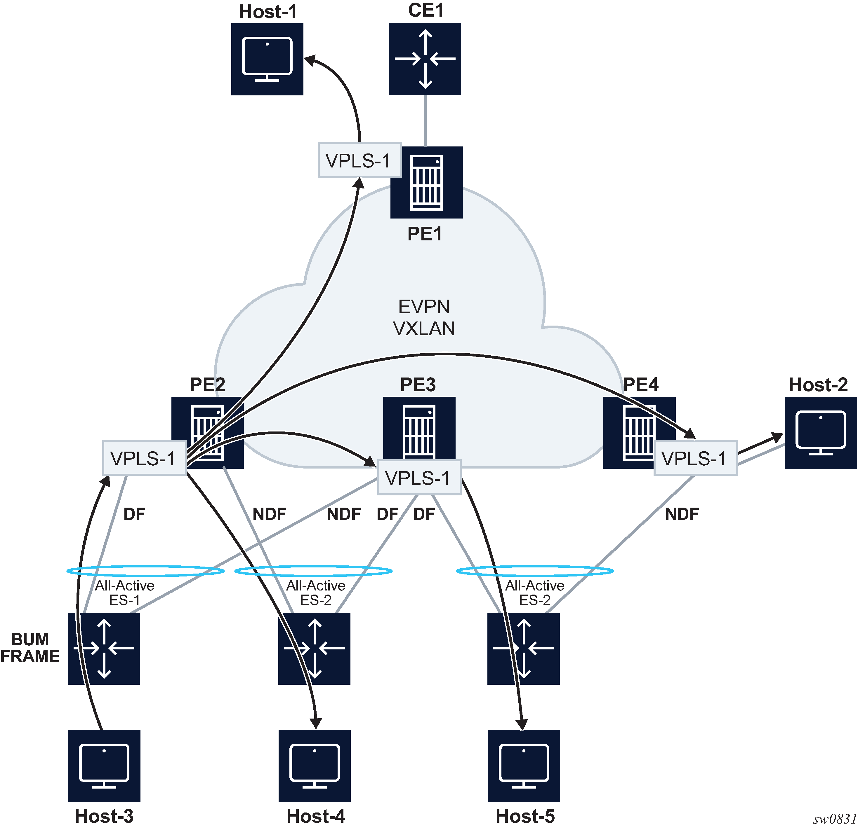
Local bias is based on the following principles:
Every PE knows the IP addresses associated with the other PEs with which it has shared multihomed ESs.
When the PE receives a BUM frame from a VXLAN bind, it looks up the source IP address in the tunnel header and filters out the frame on all local interfaces connected to ESs that are shared with the ingress PE.
With this approach, the ingress PE must perform replication locally to all directly-attached ESs (regardless of the DF Election state) for all flooded traffic coming from the access interfaces. BUM frames received on any SAP are flooded to:
local non-ES SAPs and non-ES SDP-binds
local all-active ES SAPs (DF and NDF)
local single-active ES SDP-binds and SAPs (DF only)
EVPN-VXLAN destinations
As an example, in EVPN-VXLAN multihoming with local bias, PE2 receives BUM traffic from Host-3 and it forwards it to the remote PEs and the local ES SAP, even though the SAP is in NDF state.
The following rules apply to egress PE forwarding for EVPN-VXLAN services:
The source VTEP is looked up for BUM frames received on EVPN-VXLAN.
If the source VTEP matches one of the PEs with which the local PE shares both an ES and a VXLAN service:
the local PE is not forwarded to the shared ES local SAPs
the local PE forwards normally to ES SAPs unless they are in NDF state
Because there is no multicast label or multicast B-MAC in VXLAN, the egress PE only identifies BUM traffic using the customer MAC DA; as a result, BM or unknown MAC DAs identify BUM traffic.
For example, in EVPN-VXLAN multihoming with local bias, PE3 receives BUM traffic on VXLAN. PE3 identifies the source VTEP as a PE with which two ESs are shared, therefore it does not forward the BUM frames to the two shared ESs. It forwards to the non-shared ES (Host-5) because it is in DF state. PE4 receives BUM traffic and forwards it based on normal rules because it does not share any ESs with PE2.
The following command can be used to check whether the local PE has enabled the local bias procedures for a specific ES:
A:PE-2# tools dump service system bgp-evpn ethernet-segment "ES-1" local-bias
-------------------------------------------------------------------------------
[04/01/2019 08:45:08] Vxlan Local Bias Information
----------------------------------------------------------------------+--------
Peer                                                                  | Enabled
----------------------------------------------------------------------+--------
192.0.2.3                                                             | Yes
-------------------------------------------------------------------------------
Known limitations for local bias
In EVPN MPLS networks, an ingress PE that uses ingress replication to flood unknown unicast traffic pushes a BUM MPLS label that is different from a unicast label. The egress PEs use this BUM label to identify such BUM traffic to apply DF filtering for All-Active multihomed sites. In PBB-EVPN, in addition to the multicast label, the egress PE can also rely on the multicast B-MAC DA to identify customer BUM traffic.
In VXLAN there are no BUM labels or any tunnel indication that can assist the egress PE in identifying the BUM traffic. As such, the egress PE must solely rely on the C-MAC destination address, which may create some transient issues that are depicted in EVPN-VXLAN multihoming and unknown unicast issues.
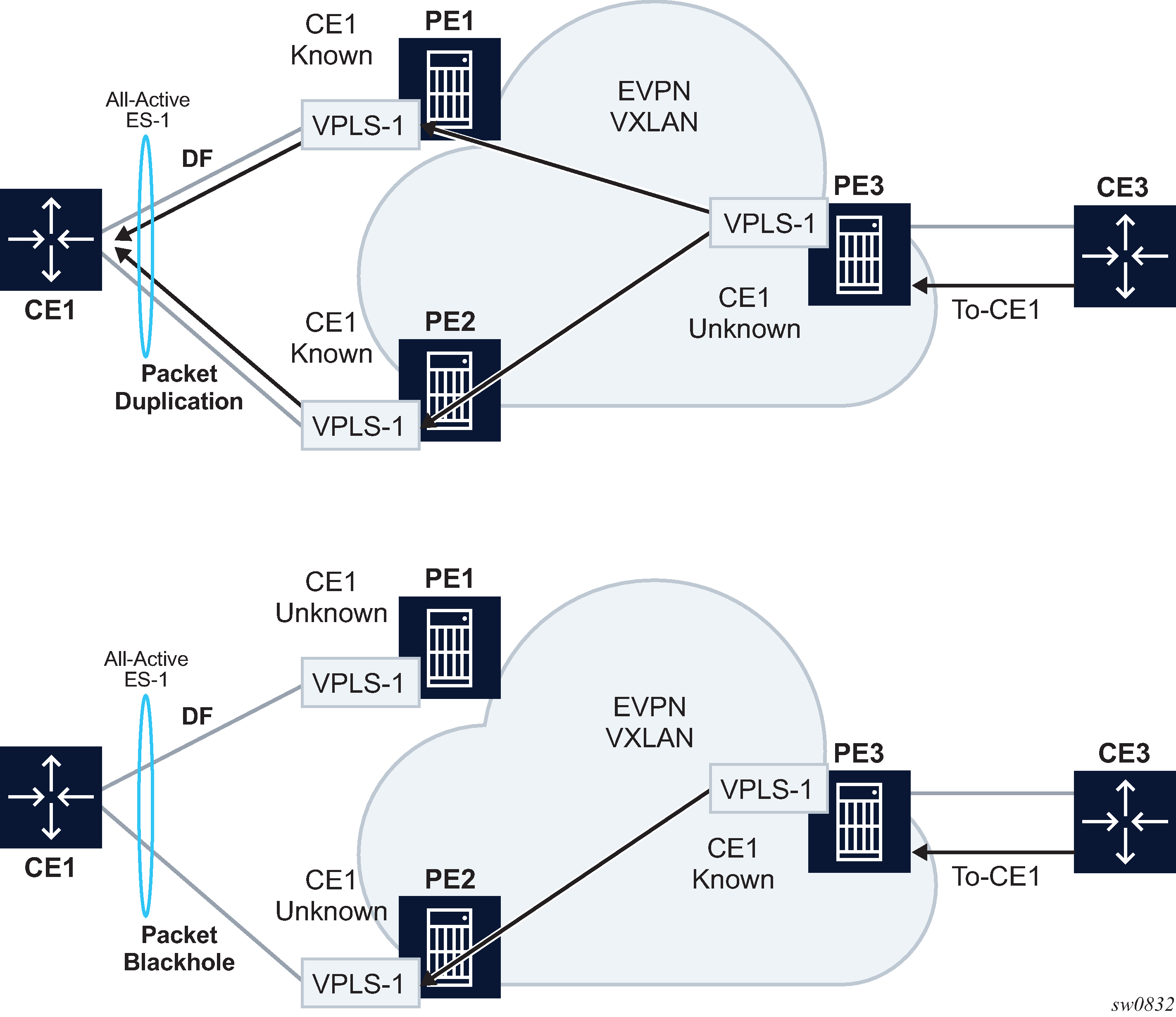
As shown in EVPN-VXLAN multihoming and unknown unicast issues, top diagram, in absence of the mentioned unknown unicast traffic indication there can be transient duplicate traffic to All-Active multihomed sites under the following condition: CE1’s MAC address is learned by the egress PEs (PE1 and PE2) and advertised to the ingress PE3; however, the MAC advertisement has not been received or processed by the ingress PE, resulting in the host MAC address to be unknown on the ingress PE3 but known on the egress PEs. Therefore, when a packet destined for CE1 address arrives on PE3, it floods it through ingress replication to PE1 or PE2 and, because CE1’s MAC is known to PE1 and PE2, multiple copies are sent to CE1.
Another issue is shown at the bottom of EVPN-VXLAN multihoming and unknown unicast issues. In this case, CE1’s MAC address is known on the ingress PE3 but unknown on PE1 and PE2. If PE3’s aliasing hashing picks up the path to the ES’ NDF, a black-hole occurs.
The above two issues are solved in MPLS, as unicast known and unknown frames are identified with different labels.
Finally, another issue is described in Blackhole created by a remote SAP shutdown. Under normal circumstances, when CE3 sends BUM traffic to PE3, the traffic is ‟local-biased” to PE3’s SAP3 even though it is NDF for the ES. The flooded traffic to PE2 is forwarded to CE2, but not to SAP2 because the local bias split-horizon filtering takes place.
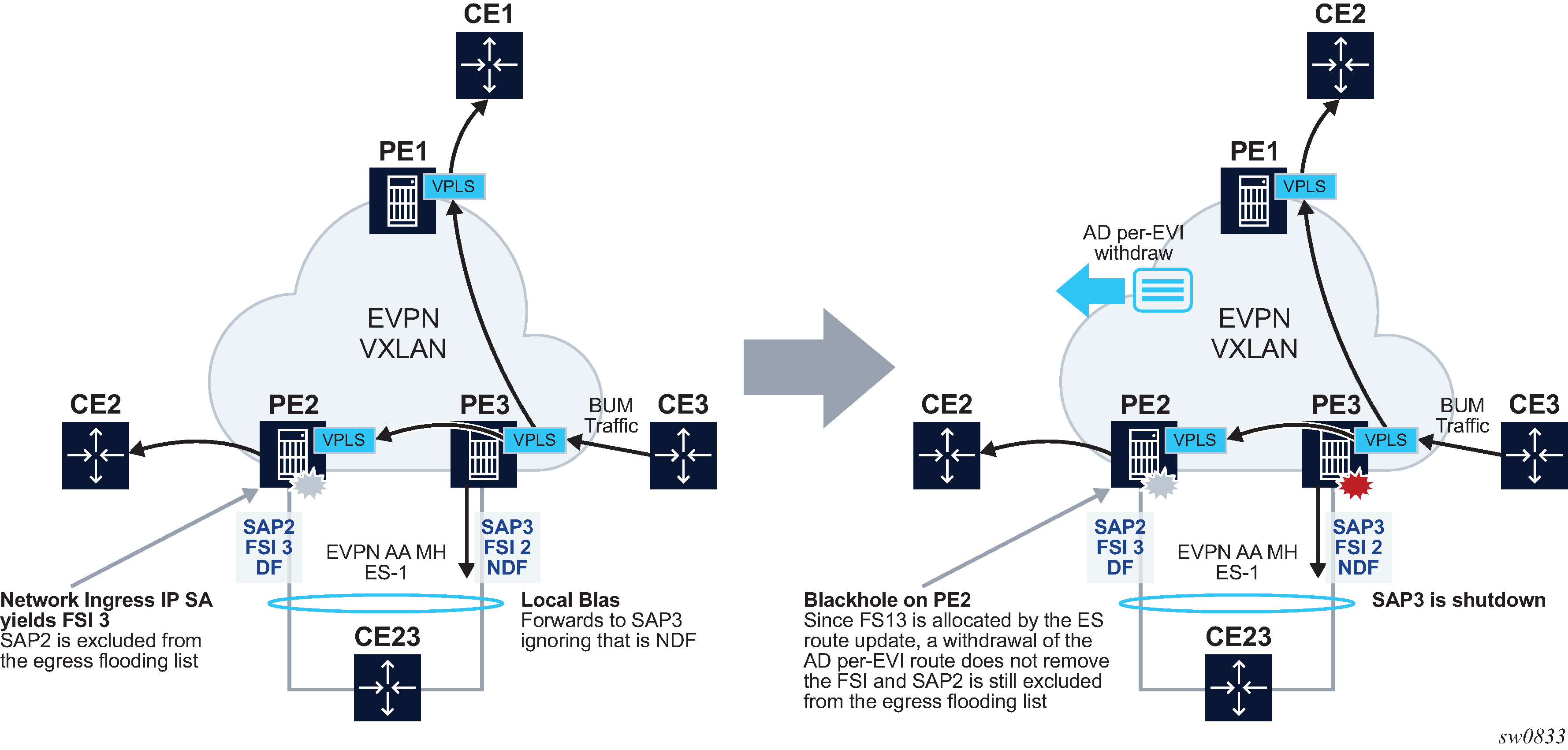
The right side of the diagram in Blackhole created by a remote SAP shutdown shows an issue when SAP3 is manually shutdown. In this case, PE3 withdraws the AD per-EVI route corresponding to SAP3; however, this does not change the local bias filtering for SAP2 in PE2. Therefore, when CE3 sends BUM traffic, it can neither be forwarded to CE23 via local SAP3 nor can it be forwarded by PE2.
Non-system IPv4 and IPv6 VXLAN termination for EVPN VXLAN multihoming
EVPN VXLAN multihoming is supported on VPLS and R-VPLS services when the PEs use non-system IPv4 or IPv6 termination, however, as with EVPN VPWS services, additional configuration steps are required.
The configure service system bgp-evpn eth-seg es-orig-ip ip-address command must be configured with the non-system IPv4 or IPv6 address used for the EVPN-VXLAN service. This command modifies the originating-ip field in the ES routes advertised for the Ethernet Segment, and makes the system use this IP address when adding the local PE as DF candidate.
The configure service system bgp-evpn eth-seg route-next-hop ip-address command must also be configured with the non-system IP address. This command changes the next-hop of the ES and AD per-ES routes to the configured address.
Finally, the non-system IP address (in each of the PEs in the ES) must match in these three commands for the local PE to be considered suitable for DF election:
es-orig-ip ip-address
route-next-hop ip-address
vxlan-src-vtep ip-address
EVPN for MPLS tunnels
This section provides information about EVPN for MPLS tunnels.
BGP-EVPN control plane for MPLS tunnels
EVPN routes and usage lists all the EVPN routes and their usage in EVPN-VXLAN, EVPN-MPLS, and PBB-EVPN.
| EVPN route | Usage | EVPN-VXLAN | EVPN-MPLS | PBB-EVPN |
|---|---|---|---|---|
|
Type 1 - Ethernet Auto-Discovery route (A-D) |
Mass-withdraw, ESI labels, Aliasing |
Y |
Y |
— |
|
Type 2 - MAC/IP Advertisement route |
MAC/IP advertisement, IP advertisement for ARP resolution |
Y |
Y |
Y |
|
Type 3 - Inclusive Multicast Ethernet Tag route |
Flooding tree setup (BUM flooding) |
Y |
Y |
Y |
|
Type 4 - ES route |
ES discovery and DF election |
Y |
Y |
Y |
|
Type 5 - IP Prefix advertisement route |
IP Routing |
Y |
Y |
— |
|
Type 6 - Selective Multicast Ethernet Tag route |
Signal interest on a multicast group |
Y |
Y |
— |
| Type 7 - Multicast Join Synch route |
Join a multicast group on a multihomed ES |
Y |
Y |
— |
| Type 8 - Multicast Leave Synch route |
Leave a multicast group on a multihomed ES |
Y |
Y |
— |
| Type 10 - Selective Provider Multicast Service Interface Auto-Discovery route | Signal and setup Selective Provider Tunnels for IP Multicast | - | Y | - |
RFC 7432 describes the BGP-EVPN control plane for MPLS tunnels. If EVPN multihoming is not required, two route types are needed to set up a basic EVI (EVPN Instance): MAC/IP Advertisement and the Inclusive Multicast Ethernet Tag routes. If multihoming is required, the ES and the Auto-Discovery routes are also needed.
The route fields and extended communities for route types 2 and 3 are shown in EVPN-VXLAN required routes and communities. BGP-EVPN control plane for VXLAN overlay tunnels The changes compared to their use in EVPN-VXLAN are described below.
EVPN route type 3 - inclusive multicast Ethernet tag route
As in EVPN-VXLAN, route type 3 is used for setting up the flooding tree (BUM flooding) for a specified VPLS service. The received inclusive multicast routes add entries to the VPLS flood list in the 7705 SAR Gen 2. Ingress replication, p2mp mLDP, and composite tunnels are supported as tunnel types in route type 3 when BGP-EVPN MPLS is enabled
The following route values are used for EVPN-MPLS services:
-
Route Distinguisher is taken from the RD of the VPLS service within the BGP context. The RD can be configured or derived from the bgp-evpn evi value.
-
Ethernet Tag ID is 0.
-
IP address length is always 32.
-
Originating router's IP address carries an IPv4 or IPv6 address.
-
The PMSI attribute can have different formats depending on the tunnel type enabled in the service.
-
Tunnel type = Ingress replication (6)
The route is referred to as an Inclusive Multicast Ethernet Tag IR (IMET-IR) route and the PMSI Tunnel Attribute (PTA) fields are populated as follows:
-
Leaf not required for Flags.
-
MPLS label carries the MPLS label allocated for the service in the high-order 20 bits of the label field.
Unless bgp-evpn mpls ingress-replication-bum-label is configured in the service, the MPLS label used is the same as that used in the MAC/IP routes for the service.
-
Tunnel endpoint is equal to the originating IP address.
-
-
Tunnel type=p2mp mLDP (2)
The route is referred to as an IMET-P2MP route and its PTA fields are populated as follows:
-
Leaf not required for Flags.
-
MPLS label is 0.
-
Tunnel endpoint includes the route node address and an opaque number. This is the tunnel identifier that the leaf-nodes use to join the mLDP P2MP tree.
-
-
Tunnel type=Composite tunnel (130)
The route is referred to as an IMET-P2MP-IR route and its PTA fields are populated as follows:
-
Leaf not required for Flags.
-
MPLS label 1 is 0.
-
Tunnel endpoint identifier includes the following:
- MPLS label2
- non-zero, downstream allocated label (like any other IR label). The leaf-nodes use the label to set up an EVPN-MPLS destination to the root and add it to the default-multicast list.
- mLDP tunnel identifier
- the route node address and an opaque number. This is the tunnel identifier that the leaf-nodes use to join the mLDP P2MP tree.
-
-
IMET-P2MP-IR routes are used in EVIs with a few root nodes and a significant number of leaf-only PEs. In this scenario, a combination of P2MP and IR tunnels can be used in the network, such that the root nodes use P2MP tunnels to send broadcast, Unknown unicast, and Multicast traffic but the leaf-PE nodes use IR to send traffic to the roots. This use case is documented in IETF RFC 8317 and the main advantage it offers is the significant savings in P2MP tunnels that the PE/P routers in the EVI need to handle (as opposed to a full mesh of P2MP tunnels among all the PEs in an EVI).
In this case, the root PEs signals a special tunnel type in the PTA, indicating that they intend to transmit BUM traffic using an mLDP P2MP tunnel but they can also receive traffic over an IR evpn-mpls binding. An IMET route with this special ‟composite” tunnel type in the PTA is called an IMET-P2MP-IR route and the encoding of its PTA is shown in Composite p2mp mLDP and IR tunnels—PTA.

EVPN route type 2 - MAC/IP advertisement route
The 7705 SAR Gen 2 router generates this route type for advertising MAC addresses (and IP addresses if proxy-ARP/proxy-ND is enabled). If mac-advertisement is enabled, the router generates MAC advertisement routes for the following:
-
learned MACs on SAPs or SDP bindings
-
conditional static MACs
Note: The unknown-mac-route is not supported for EVPN-MPLS services.
The route type 2 generated by a router uses the following fields and values:
-
Route Distinguisher is taken from the RD of the VPLS service within the BGP context. The RD can be configured or derived from the bgp-evpn evi value.
-
Ethernet Segment Identifier (ESI) is zero for MACs learned from single-homed CEs and different from zero for MACs learned from multihomed CEs.
-
Ethernet Tag ID is 0.
-
MAC address length is always 48.
-
MAC address can be learned or statically configured.
-
IP address and IP address length:
-
It is the IP address associated with the MAC being advertised with a length of 32 (or 128 for IPv6).
-
In general, any MAC route without IP has IPL=0 (IP length) and the IP is omitted.
-
When received, any IPL value not equal to zero, 32, or 128 discards the route.
-
MPLS Label 1 carries the MPLS label allocated by the system to the VPLS service. The label value is encoded in the high-order 20 bits of the field and is the same label used in the routes type 3 for the same service unless bgp-evpn mpls ingress-replication-bum-label is configured in the service.
-
-
MPLS Label 2 is 0.
-
The MAC mobility extended community is used for signaling the sequence number in case of MAC moves and the sticky bit in case of advertising conditional static MACs. If a MAC route is received with a MAC mobility ext-community, the sequence number and the 'sticky' bit are considered for the route selection.
When EVPN multihoming is enabled in the system, two more routes are required. EVPN routes type 1 and 4 shows the fields in routes type 1 and 4 and their associated extended communities.

EVPN route type 1 - Ethernet auto-discovery route (AD route)
The 7705 SAR Gen 2 router generates this route type for advertising for multihoming functions. The system can generate two types of AD routes:
-
Ethernet AD route per-ESI (Ethernet Segment ID)
-
Ethernet AD route per-EVI (EVPN Instance)
The Ethernet AD per-ESI route generated by a router uses the following fields and values:
-
Route Distinguisher is taken from the system level RD or service level RD.
-
Ethernet Segment Identifier (ESI) contains a 10-byte identifier as configured in the system for a specified ethernet-segment.
-
Ethernet Tag ID is MAX-ET (0xFFFFFFFF). This value is reserved and used only for AD routes per ESI.
-
MPLS label is 0.
-
ESI Label Extended community includes the single-active bit (0 for all-active and 1 for single-active) and ESI label for all-active multihoming split-horizon.
-
Route target extended community is taken from the service level RT or an RT-set for the services defined on the Ethernet segment.
The system can either send a separate Ethernet AD per-ESI route per service, or a few Ethernet AD per-ESI routes aggregating the route-targets for multiple services. While both alternatives inter-operate, RFC 7432 states that the EVPN Auto-Discovery per-ES route must be sent with a set of route-targets corresponding to all the EVIs defined on the Ethernet Segment (ES). Either option can be enabled using the command: config>service>system>bgp-evpn#ad-per-es-route-target <[evi-rt ] | [evi-rt-set]> route-distinguisher ip-address [extended-evi-range]
The default option ad-per-es-route-target evi-rt configures the system to send a separate AD per-ES route per service. When enabled, the evi-rt-set option supports route aggregation: a single AD per-ES route with the associated RD (ip-address:1) and a set of EVI route targets are advertised (up to a maximum of 128). When the number of EVIs defined in the Ethernet Segment is significant (therefore the number of route-targets), the system sends more than one route. For example:
-
AD per-ES route for evi-rt-set 1 is sent with RD ip-address:1
-
AD per-ES route for evi-rt-set 2 is sent with RD ip-address:2
-
up to an AD per-ES route is sent with RD ip-address:512
The extended-evi-range option is needed for the use of evi-rt-set with a comm-val extended range of 1 through 65535. This option is recommended when EVIs greater than 65535 are configured in some services. In this case, there are more EVIs for which the route-targets must be packed in the AD per-ES routes. This command option extends the maximum number of AD per-ES routes that can be sent (since the RD now supports up to ip-address:65535) and allows many more route-targets to be included in each set.
The Ethernet AD per-EVI route generated by a router uses the following fields and values:
-
Route Distinguisher is taken from the service level RD.
-
Ethernet Segment Identifier (ESI) contains a 10-byte identifier as configured in the system for a specified Ethernet Segment.
-
Ethernet Tag ID is 0.
-
MPLS label encodes the unicast label allocated for the service (high-order 20 bits).
-
Route-target extended community is taken from the service level RT.
EVPN route type 4 - ES route
The router generates this route type for multihoming ES discovery and DF (Designated Forwarder) election.
-
Route Distinguisher is taken from the service level RD.
-
Ethernet Segment Identifier (ESI) contains a 10-byte identifier as configured in the system for a specified ethernet-segment.
-
The value of ES-import route-target community is automatically derived from the MAC address portion of the ESI. This extended community is treated as a route-target and is supported by RT-constraint (route-target BGP family).
EVPN route type 5 - IP prefix route
IP Prefix Routes are also supported for MPLS tunnels. The route fields for route type 5 are shown in EVPN route-type 5 . The 7705 SAR Gen 2 router generates this route type for advertising IP prefixes in EVPN using the same fields that are described in section BGP-EVPN control plane for VXLAN overlay tunnels, with the following exceptions:
-
MPLS label carries the MPLS label allocated for the service.
-
This route is sent with the RFC 5512 tunnel encapsulation extended community with the tunnel type value set to MPLS
RFC 5512 - BGP tunnel encapsulation extended community
The following routes are sent with the RFC 5512 BGP Encapsulation Extended Community: MAC/IP, Inclusive Multicast Ethernet Tag, and AD per-EVI routes. ES and AD per-ESI routes are not sent with this Extended Community.
The router processes the following BGP Tunnel Encapsulation tunnel values registered by IANA for RFC 5512:
-
VXLAN encapsulation is 8.
-
MPLS encapsulation is 10.
Any other tunnel value makes the route 'treat-as-withdraw'.
If the encapsulation value is MPLS, the BGP validates the high-order 20-bits of the label field, ignoring the low-order 4 bits. If the encapsulation is VXLAN, the BGP takes the entire 24-bit value encoded in the MPLS label field as the VNI.
If the encapsulation extended community (as defined in RFC 5512) is not present in a received route, BGP treats the route as an MPLS or VXLAN-based configuration of the config>router>bgp>neighbor# def-recv-evpn-encap [mpls | vxlan] command. The command is also available at the bgp and group levels.
EVPN for MPLS tunnels in VPLS services
EVPN can be used in MPLS networks where PEs are interconnected through any type of tunnel, including RSVP-TE, Segment-Routing TE, LDP, BGP, Segment Routing IS-IS, Segment Routing OSPF, RIB-API, MPLS-forwarding-policy, SR-Policy, or MPLSoUDP. As with VPRN services, tunnel selection for a VPLS service (with BGP-EVPN MPLS enabled) is based on the auto-bind-tunnel command. The BGP EVPN routes next-hops can be IPv4 or IPv6 addresses and can be resolved to a tunnel in the IPv4 tunnel-table or IPv6 tunnel-table.
EVPN-MPLS is modeled similarly to EVPN-VXLAN and uses a VPLS service where EVPN-MPLS ‟bindings” can coexist with SAPs and SDP-bindings.
VPLS service with EVPN-MPLS
*A:node-2config>service>vpls# info
----------------------------------------------
  description "evpn-mpls-service"
  bgp
  bgp-evpn
    evi 10
    mpls bgp 1
      no shutdown
      auto-bind-tunnel resolution any
  sap 1/1/1:1 create
  exit
  spoke-sdp 1:1 create
First configure a bgp-evpn context where VXLAN must be disabled and MPLS enabled. In addition to enabling MPLS the command, the minimum set of commands to be configured to set up the EVPN-MPLS instance are the evi and the auto-bind-tunnel resolution commands. The relevant configuration options are the following.
evi {1..16777215} — This EVPN identifier is unique in the system and is used for the service-carving algorithm used for multihoming (if configured), and for auto-deriving the route target and route distinguishers (if lower than 65535) in the service. It can be used for EVPN-MPLS and EVPN-VXLAN services.
The following options are supported:
- If this EVPN identifier is not specified, the value is zero and no route distinguisher or route target is automatically derived from it.
- If the specified EVPN identifier is lower than 65535 and no other route distinguisher or
route target is configured in the service, the following applies:
- The route distinguisher is derived from <system_ip>:evi.
- The route target is derived from <autonomous-system>:evi.
- If the specified EVPN identifier is higher than 65535 and no other route distinguisher
or route target is configured in the service, the following applies:
- The route distinguisher cannot be automatically derived. An error is generated if enabling EVPN is attempted without a route distinguisher. A manual or an auto-rd route distinguisher must be configured.
- The route target can only be automatically derived if the
evi-three-byte-auto-rt command is configured. If configured, the
route target is automatically derived in accordance with the following rules described
in RFC8365.
- The route target is composed of ASN(2-octets):A/type/D-ID/EVI.
- The ASN is a 2-octect value configured in the system. For AS numbers exceeding the 2-byte limit, the low order 16-bit value is used.
- The A=0 value is used for auto-derivation.
- The type=4 (EVI-based) is used.
- The BGP instance is encoded using D-ID= [1..2]. This allows the automatic derivation of different RTs in multi-instance services. The value is inherited from the corresponding BGP instance.
- EVI indicates the configured EVI in the service
Consider a service with the following characteristics:
- ASN=64500
- VPLS with BGP instance bgp 1 for EVPN-MPLS
- EVI=100000
The automatically derived route targets for this service are:
- bgp 1 — 64500:1090619040 (ASN:0x410186A0)
- bgp 2 — 64500:1107396256 (ASN:0x420186A0)
If this EVPN identifier is not specified, the value is zero and no route distinguisher or route targets is automatically derived from it. If specified and no other route distinguisher/route target are configured in the service:, then the following applies:
-
the route distinguisher is derived from: <system_ip>:evi
-
the route target is derived from: <autonomous-system>:evi
When the evi is configured, a configure service vpls bgp node (even empty) is required to allow the user to see the correct information about the show service id 1 bgp and show service system bgp-route-distinguisher commands.
The following options are specific to EVPN-MPLS and are configured in the configure service vpls bgp-evpn mpls context:
-
control word
Enable or disable control word capability to guarantee interoperability to other vendors. When enabled along with the following command, the control word capability is signaled in the C flag of the EVPN Layer 2 attributes extended community, as defined in draft-ietf-bess-rfc7432bis;- MD-CLI
configure service vpls bgp-evpn routes incl-mcast advertise-l2-attributes - classic
CLI
configure service vpls bgp-evpn incl-mcast-l2-attributes-advertisement
Note: The control-word is required, as described in RFC 7432, to avoid frame disordering. - MD-CLI
- hash-label
This command enables or disables the use of the hash label (also known as the Flow Aware Transport (FAT) label) in the EVPN unicast destinations. Similar to the control-word command, when the hash-label command is enabled along with the incl-mcast-l2-attributes-advertisement (advertise-l2-attributes in classic CLI) command, the F-flag capability is signaled in the EVPN Layer 2 attributes extended community, as described in draft-ietf-bess-rfc7432bis. In addition:
- When the hash-label command is enabled and advertise-l2-attributes false is configured, the hash label is always pushed to a unicast EVPN destination. The hash label is never used for BUM packets, as described in draft-ietf-bess-rfc7432bis.
- When the hash-label command is enabled and advertise-l2-attributes true is configured, the F-bit is set in the Layer-2 attributes extended community of the EVPN Inclusive Multicast Ethernet Tag (IMET) route for the service. The hash label toward a specific remote PE is pushed in the datapath only if the remote PE previously signaled support for the hash label (F=1). Otherwise, the unicast EVPN destination is brought operationally down, and the corresponding operational flag indicates the reason.
-
auto bind tunnel
This command selects the type of MPLS transport tunnel to use for a specific instance; this command is used in the same way as in VPRN services.
For BGP-EVPN MPLS, you must explicitly add BGP to the resolution filter in EVPN (BGP is implicit in VPRNs).
-
force VLAN VC forwarding
This option allows the system to preserve the VLAN ID and P-bits of the service-delimiting qtag in a new tag added in the customer frame before sending it to the EVPN core.
Note: You can use this option in conjunction with the sap ingress vlan-translation command. If so, the configured translated VLAN ID is sent to the EVPN binds as opposed to the service-delimiting tag VLAN ID. If the ingress SAP/binding is null-encapsulated, the output VLAN ID and pbits are zero. -
force QinQ VC forwarding with c-tag-c-tag or s-tag-c-tag
This command allows the system to preserve the VLAN ID and pbits of the service-delimiting Q-tags (up to two tags) in customer frames before sending them to the EVPN core.
Note: You can use this option in conjunction with the sap ingress qinq-vlan-translation s-tag.c-tag command. If so, the configured translated S-tag and C-tag VLAN IDs are the VLAN IDs sent to the EVPN binds as opposed to the service-delimiting tags VLAN IDs. If the ingress SAP or binding is null-encapsulated, the output VLAN ID and pbits are zero. -
split horizon group
This command allows the association of a user-created split horizon group to all the EVPN-MPLS destinations. See EVPN and VPLS integration for more information.
-
ecmp
Set this option to a value greater than 1 to activate aliasing to the remote PEs that are defined in the same all-active multihoming ES.
-
ingress replication bum label
You can use this option when you want the PE to advertise a label for BUM traffic (Inclusive Multicast routes) that is different from the label advertised for unicast traffic (with the MAC/IP routes). This is useful to avoid potential transient packet duplication in all-active multihoming.
In addition to the preceding options, the following bgp-evpn commands are also available for EVPN-MPLS services:
-
mac-advertisement
-
mac-duplication and settings
-
incl-mcast advertise-l2-attributes (MD-CLI)
incl-mcast-l2-attributes-advertisement (classic CLI)
This function enables the advertisement and processing of the EVPN Layer 2 attributes extended community. The control word, hash-label configuration, and the service-MTU value are advertised in the extended community. On reception, the received MTU, hash-label, and control-word flags are compared with the local MTU and hash-label or control-word configuration. In case of a mismatch in any of the three settings, the EVPN destination goes operationally down, and the corresponding operational flag describes the mismatch. The absence of an IMET route from an egress PE or the absence of the EVPN Layer 2 attributes extended community on a received IMET route from the PE, causes the route to bring down the EVPN destinations to that PE.
-
ignore-mtu-mismatch
This command makes the router ignore the received Layer 2 MTU in the EVPN Layer 2 attributes extended community of the IMET route for a peer. If disabled, the local service MTU is compared against the received Layer 2 MTU. If there is a mismatch, the EVPN destinations to the peer stay oper-state down.
When EVPN-MPLS is established among some PEs in the network, EVPN unicast and multicast ‟bindings” to the remote EVPN destinations are created on each PE. A specified ingress PE creates the following:
-
A unicast EVPN-MPLS destination binding to a remote egress PE as soon as a MAC/IP route is received from that egress PE.
-
A multicast EVPN-MPLS destination binding to a remote egress PE, if and only if the egress PE advertises an Inclusive Multicast Ethernet Tag Route with a BUM label. That is only possible if the egress PE is configured with ingress-replication-bum-label.
These bindings, as well as the MACs learned on them, can be checked using the following commands.
EVPN-MPLS destination bindings
In the following example, the remote PE(192.0.2.69) is configured with no ingress-replication-bum-label and PE(192.0.2.70) is configured with ingress-replication-bum-label. As a result, the device has a single EVPN-MPLS destination binding to PE(192.0.2.69) and two bindings (unicast and multicast) to PE(192.0.2.70).
show service id 1 evpn-mpls===============================================================================
BGP EVPN-MPLS Dest
===============================================================================
TEP Address Egr Label Num. MACs Mcast Last Change
Transport
-------------------------------------------------------------------------------
192.0.2.69 262118 1 Yes 06/11/2015 19:59:03
ldp
192.0.2.70 262139 0 Yes 06/11/2015 19:59:03
ldp
192.0.2.70 262140 1 No 06/11/2015 19:59:03
ldp
192.0.2.72 262140 0 Yes 06/11/2015 19:59:03
ldp
192.0.2.72 262141 1 No 06/11/2015 19:59:03
ldp
192.0.2.73 262139 0 Yes 06/11/2015 19:59:03
ldp
192.0.2.254 262142 0 Yes 06/11/2015 19:59:03
bgp
-------------------------------------------------------------------------------
Number of entries : 7
-------------------------------------------------------------------------------
===============================================================================
show service id 1 fdb detail ===============================================================================
Forwarding Database, Service 1
===============================================================================
ServId MAC Source-Identifier Type Last Change
Age
-------------------------------------------------------------------------------
1 00:ca:fe:ca:fe:69 eMpls: EvpnS 06/11/15 21:53:48
192.0.2.69:262118
1 00:ca:fe:ca:fe:70 eMpls: EvpnS 06/11/15 19:59:57
192.0.2.70:262140
1 00:ca:fe:ca:fe:72 eMpls: EvpnS 06/11/15 19:59:57
192.0.2.72:262141
-------------------------------------------------------------------------------
No. of MAC Entries: 3
-------------------------------------------------------------------------------
Legend: L=Learned O=Oam P=Protected-MAC C=Conditional S=Static
===============================================================================
EVPN and VPLS integration
The 7705 SAR Gen 2 EVPN implementation supports RFC 8560 so that EVPN-MPLS and VPLS can be integrated into the same network and within the same service. Because EVPN is not deployed in green-field networks, this feature is useful for the integration between both technologies and even for the migration of VPLS services to EVPN-MPLS.
The following behavior enables the integration of EVPN and SDP-bindings in the same VPLS network.
Systems with EVPN endpoints and SDP-bindings to the same far-end bring down the SDP-bindings.
The router allows the establishment of an EVPN endpoint and an SDP-binding to the same far-end, but the SDP-binding is kept operationally down. Only the EVPN endpoint is operationally up. This applies to spoke-SDPs (manual, BGP-AD, and BGP-VPLS) and mesh-SDPs. It is also possible between VXLAN and SDP bindings.
If there is an existing EVPN endpoint to a specified far-end and a spoke-SDP establishment is attempted, the spoke-SDP is set up but kept down with an operational flag indicating that there is an EVPN route to the same far-end.
If there is an existing spoke-SDP and a valid or used EVPN route arrives, the EVPN endpoint is set up and the spoke-SDP is brought down with an operational flag indicating that there is an EVPN route to the same far-end.
In the case of an SDP-binding and EVPN endpoint to different far-end IPs on the same remote PE, both links are up. This may occur if the SDP-binding is terminated in an IPv6 or IPv4 address that is different from the system address where the EVPN endpoint is terminated.
The user can add spoke-SDPs and all the EVPN-MPLS endpoints in the same SHG.
A CLI command is added under the bgp-evpn>mpls context so that the EVPN-MPLS endpoints can be added to an SHG:
bgp-evpn mpls [no] split-horizon-group group-name
The bgp-evpn mpls split-horizon-group command must reference a user-configured SHG. User-configured SHGs can be configured within the service context. The same group-name can be associated with SAPs, spoke-SDPs, pw-templates, pw-template-bindings, and EVPN-MPLS endpoints.
If the bgp-evpn mpls split-horizon-group command is not used, the default SHG (that contains all the EVPN endpoints) is still used but cannot be referred to on SAPs/spoke-SDPs.
SAPs and SDP-bindings that share the same SHG of the EVPN-MPLS provider-tunnel are brought operationally down if the point-to-multipoint tunnel is operationally up.
The system disables the advertisement of MACs learned on spoke-SDPs or SAPs that are part of an EVPN SHG.
When the SAPs and spoke-SDPs (manual or BGP-AD/VPLS-discovered) are configured within the same SHG as the EVPN endpoints, MAC addresses are still learned on them but they are not advertised in EVPN.
The preceding statement is also true if proxy-ARP/ND is enabled and an IP→MAC pair is learned on a SAP or SDP-binding that belongs to the EVPN SHG.
The SAPs and spoke-SDPs added to an EVPN SHG should not be part of any EVPN multihomed ES. If that occurs, the PE would still advertise the AD per-EVI route for the SAP or spoke-SDP, attracting EVPN traffic that could not possibly be forwarded to that SAP or SDP-binding.
Similar to the preceding statement, an SHG composed of SAPs/SDP-bindings used in a BGP-MH site should not be configured under bgp-evpn>mpls>split-horizon-group. This misconfiguration would prevent forwarding of traffic from the EVPN to the BGP-MH site, regardless of the DF/NDF state.
The following figure shows an example of EVPN-VPLS integration.
Figure 21. EVPN-VPLS integration 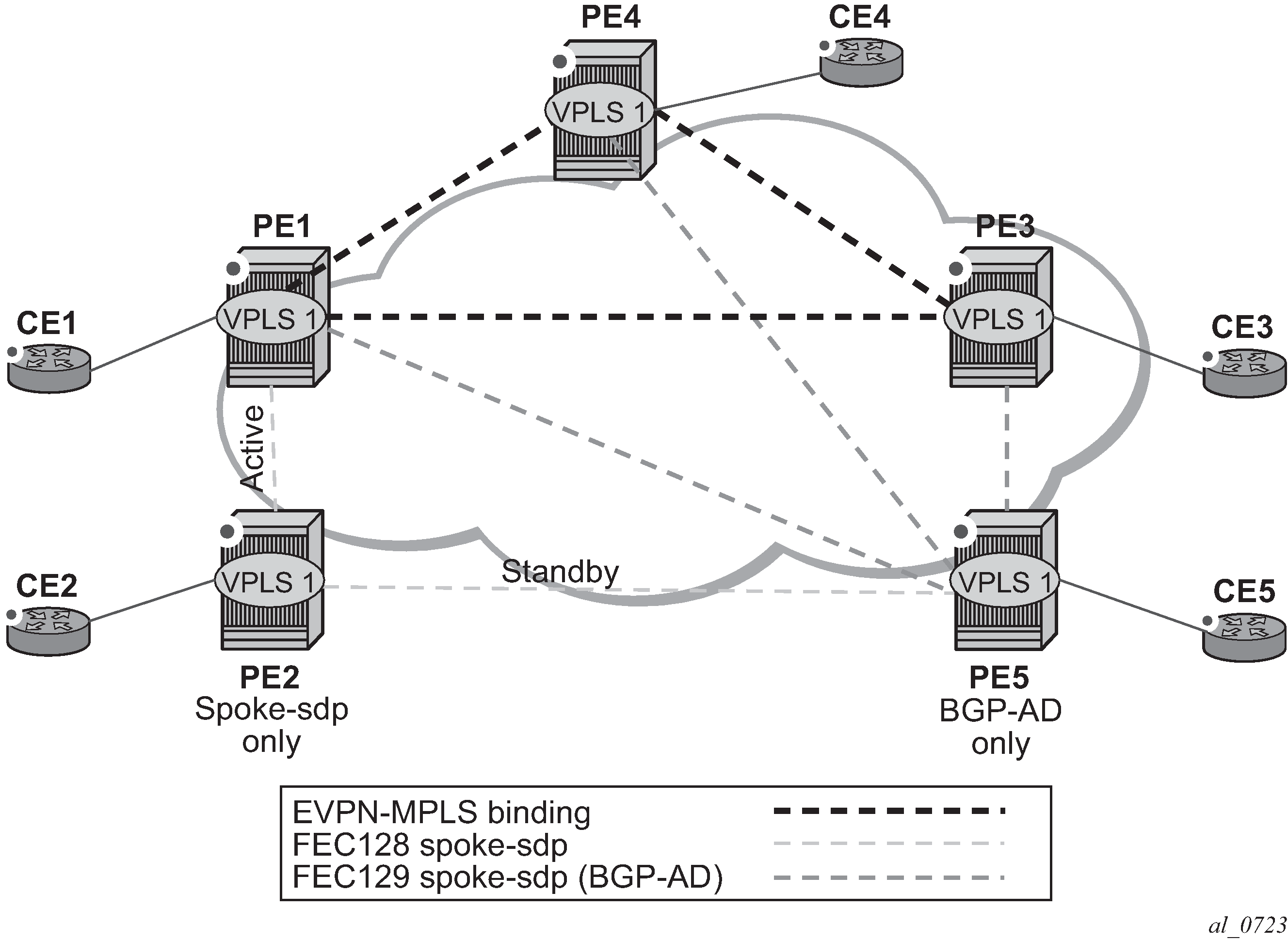
The following is an example configuration output of PE1, PE5, and PE2.
*A:PE1>config>service# info
----------------------------------------------
pw-template 1 create
vpls 1 customer 1 create
  split-horizon-group "SHG-1" create
  bgp
    route-target target:65000:1
    pw-template-binding 1 split-horizon-group SHG-1
  bgp-ad
    no shutdown
    vpls-id 65000:1
  bgp-evpn
    evi 1
    mpls bgp 1
      no shutdown
      split-horizon-group SHG-1
  spoke-sdp 12:1 create
  exit
  sap 1/1/1:1 create
  exit

*A:PE5>config>service# info
----------------------------------------------
pw-template 1 create
vpls 1 customer 1 create
  bgp
    route-target target:65000:1
    pw-template-binding 1 split-horizon-group SHG-1 # auto-created SHG
  bgp-ad
    no shutdown
    vpls-id 65000:1
  spoke-sdp 52:1 create
  exit

*A:PE2>config>service# info
----------------------------------------------
vpls 1 customer 1 create
  end-point CORE create
    no suppress-standby-signaling
  spoke-sdp 21:1 end-point CORE
    precedence primary
  spoke-sdp 25:1 end-point CORE
The following applies to the configuration described in the preceding example.
PE1, PE3, and PE4 have BGP-EVPN and BGP-AD enabled in VPLS-1. PE5 has BGP-AD enabled and PE2 has active/standby spoke-SDPs to PE1 and PE5. The following applies to this configuration.
PE1, PE3, and PE4 attempt to establish BGP-AD spoke-SDPs, but they are kept operationally down as long as there are EVPN endpoints active among them.
BGP-AD spoke-SDPs and EVPN endpoints are instantiated within the same split horizon group, for example, SHG-1.
Manual spoke-SDPs from PE1 and PE5 to PE2 are not part of SHG-1.
EVPN MAC advertisements
MACs learned on FEC128 spoke-SDPs are advertised normally in EVPN.
MACs learned on FEC129 spoke-SDPs are not advertised in EVPN (because they are part of SHG-1, which is the split horizon group used for bgp-evpn mpls). This prevents any data plane MACs learned on the SHG from being advertised in EVPN.
BUM operation on PE1
When CE1 sends BUM, PE1 floods to all the active bindings.
When CE2 sends BUM, PE2 sends it to PE1 (active spoke-SDP) and PE1 floods to all the bindings and SAPs.
When CE5 sends BUM, PE5 floods to the three EVPN PEs. PE1 floods to the active spoke-SDP and SAPs, never to the EVPN PEs because they are part of the same SHG.
The operation in services with BGP-VPLS and BGP-EVPN is equivalent to the operation for BGP-AD and BGP EVPN described in EVPN and VPLS integration.
EVPN single-active multihoming and BGP-VPLS integration
In a VPLS service to which multiple EVPN PEs and BGP-VPLS PEs are attached, single-active multihoming is supported on two or more of the EVPN PEs with no special considerations. However, all-active multihoming is not supported because traffic from the all-active multihomed CE could cause a MAC flip-flopping effect on remote BGP-VPLS PEs, asymmetric flows, or other issues.
The following figure shows a scenario with a single-active ES used in a service where EVPN PEs and BGP-VPLS are integrated.
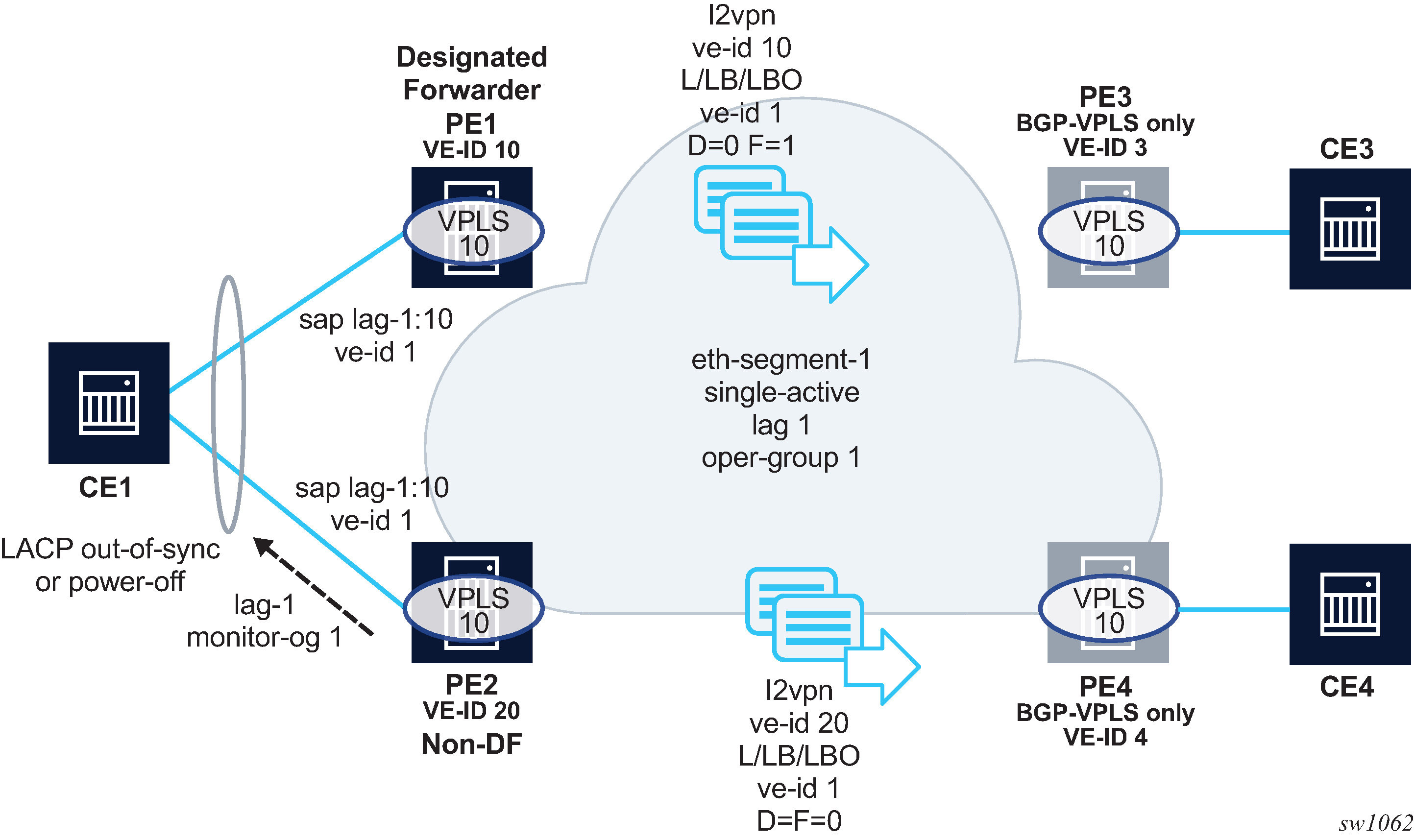
Although other single-active examples are supported, in the preceding figure, CE1 is connected to the EVPN PEs via a single LAG (lag-1). The LAG is associated with eth-segment-1 on PE1 and PE2, which is configured as single-active and with oper-group 1. PE1 and PE2 use lag>monitor-oper-group 1 so that the non-DF PE can signal the non-DF state to CE1 (in the form of Link Aggregation Control Protocol (LACP) out-of-synch or power-off).
In addition to the BGP-VPLS routes sent for the service virtual-edge (VE) ID, the multihoming PEs, in this case, must generate additional BGP-VPLS routes per ES (per VPLS service) to generate a MAC flush on the remote BGP-VPLS PEs in case of failure.
The sap>bgp-vpls-mh-veid number command should be configured on the SAPs that are part of an EVPN single-active ES. This command allows the advertisement of L2VPN routes that indicate the state of the multihomed SAPs to the remote BGP-VPLS PEs. After a DF switchover, the F and D bits of the generated L2VPN routes for the SAP VE ID are updated so that the remote BGP-VPLS PEs can perform a MAC flush operation on the service and avoid blackholes.
For example, in case of a failure on the ES SAP on PE1, PE1 must indicate to PE3 and PE4 the need to flush MAC addresses learned from PE1 (flush-all-from-me message). Otherwise, PE3 continues to send traffic with MAC DA = CE1 to PE1, and PE1 blackholes the traffic.
The following applies to the example in BGP-VPLS to EVPN integration and single-active MH.
Both ES peers (PE1 and PE2) should be configured with the same VE ID for the ES SAP. However, this is not mandatory.
In addition to the regular service ve-id L2VPN route, based on the sap>bgp-vpls-mh-ve-id configuration and on BGP VPLS being enabled, the PE advertises an L2VPN route with the following fields:
VE ID that contains the value configured using the sap bgp-vpls-mh-ve-id command
RD, RT, next hop, and other attributes that are the same as the service BGP VPLS route
L2VPN information extended community with the following flags:
D=0
This value applies If the SAP is oper-up or oper-down with a flag MHStandby (for example, the PE is non-DF in single-active MH).
This value also applies if there is an ES oper-group and the port is down as a result of the oper-group.
D=1
This value applies if the SAP is oper-down with a different flag (for example, port-down or admin-down).
F (DF bit) =1
This value applies if the SAP is oper-up. Otherwise, the value is F=0.
After a failure on the access SAP, only MAC flush messages are triggered if the bgp-vpls-mh-ve-id command is configured in the failing SAP. If the SAP is configured with VE ID 1, the following applies.
If the non-DF PE has a failure on the access SAP, PE2 sends an update with VE ID=1/D=1/F=0. This is an indication for PE3 and PE4 that the PE2 SAP is oper-down but triggering a MAC flush on PE3 and PE4 is not required.
If the DF PE has a failure on the SAP, PE1 advertises VE ID=1/D=1/F=0. After receiving this update, PE3 and PE4 flush all their MACs associated with the PE1 spoke-SDP. The failure on PE1 triggers an EVPN DF election on PE2, which becomes DF and advertises VE ID=1/D=0/F=1. This message does not trigger any MAC flush procedures.
The following considerations apply for EVPN single-active multihoming and BGP-VPLS integration.
PE3 and PE4 can be Nokia nodes running SR OS or any third-party PEs that support the procedures defined in draft-ietf-bess-vpls-multihoming, such that BGP-VPLS MAC flush signaling is understood.
PE1 and PE2 are expected to run an SR OS version that supports the configuration of the sap bgp-vpls-mh-veid number command on multihomed SAPs. Otherwise, the MAC flush behavior does not work as expected.
The procedures described in this section are also supported if the EVPN PEs use MC-LAG instead of an ES for CE1 redundancy. In this case, the SAP VE ID route for the standby PE is sent as VE ID=1/D=1/F=0, whereas the active chassis advertises VE ID=1/D=0/F=1. A switchover triggers a MAC flush on the remote PEs, as described in EVPN single-active multihoming and BGP-VPLS integration.
L2VPN routes generated for ESs or SAPs with the sap bgp-vpls-mh-veid number command are decoded in the remote nodes as BGP-MH routes (because they do not have label information) in the show router bgp routes l2vpn command and debug.
Auto-derived route-distinguisher in services with multiple BGP families
Multiple BGP families and protocols can be enabled at the same time in a VPLS. When bgp-evpn is enabled, bgp-ad and bgp-mh are also supported. A single RD is used per service and not per BGP family or protocol.
The following rules apply.
-
The VPLS RD is selected based on the following precedence.
-
Manual RD or automatic RD always take precedence when configured.
-
If manual or automatic RD is not configured, the RD is derived from the bgp-ad>vpls-id.
-
If manual RD, automatic RD, or VPLS ID are not configured, the RD is derived from the bgp-evpn>evi, except for bgp-mh, which does not support EVI-derived RD, and except when the EVI is greater than 65535. In these two cases, no EVI-derived RD is possible.
-
If manual RD, automatic RD, VPLS ID, or EVI is not configured, there is no RD and the service fails.
-
-
The selected RD (see the preceding selection criteria) is displayed by the Oper Route Dist field of the show service id bgp command.
-
The service supports dynamic RD changes. For example, the CLI allows the dynamic update of the VPLS ID, even if it is used to automatically derive the service RD for bgp-ad, bgp-vpls, or bgp-mh.
Note: When the RD changes, the active routes for that VPLS are withdrawn and readvertised with the new RD. -
If one of the mechanisms to derive the RD for a specified service is removed from the configuration, the system selects a new RD based on the preceding rules. For example, if the VPLS ID is removed from the configuration, the routes are withdrawn, the new RD selected from the EVI, and the routes readvertised with the new RD.
Note: The reconfiguration fails if the new RD already exists in a different VPLS or Epipe service. -
Because the vpls-id takes precedence over the evi when the RD is auto-derived, the existing RD is not affected when evpn is added to an existing bgp-ad service. This is important to support bgp-ad to evpn migration.
P2MP mLDP tunnels for BUM traffic in EVPN-MPLS services
P2MP mLDP tunnels for BUM traffic in EVPN-MPLS services are supported and enabled through the use of the provider-tunnel context. If EVPN-MPLS takes ownership over the provider-tunnel, bgp-ad is still supported in the service but it does not generate BGP updates, including the PMSI Tunnel Attribute. The following CLI example shows an EVPN-MPLS service that uses P2MP mLDP LSPs for BUM traffic.
*A:PE-1>config>service>vpls(vpls or b-vpls)# info
----------------------------------------------
  description "evpn-mpls-service with p2mp mLDP"
  bgp-evpn
    evi 10
    no ingress-repl-inc-mcast-advertisement
    mpls bgp 1
      no shutdown
      auto-bind-tunnel resolution any
  exit
  provider-tunnel
    inclusive
      owner bgp-evpn-mpls
      root-and-leaf
      mldp
      no shutdown
      exit
    exit
  sap 1/1/1:1 create
  exit
  spoke-sdp 1:1 create
 exit
When provider-tunnel inclusive is used in EVPN-MPLS services, the following commands can be used in the same way as for BGP-AD or BGP-VPLS services:
data-delay-interval
root-and-leaf
mldp
shutdown
The following commands are used by provider-tunnel in BGP-EVPN MPLS services:
[no] ingress-repl-inc-mcast-advertisement
This command allows you to control the advertisement of IMET-IR and IMET-P2MP-IR routes for the service. See BGP-EVPN control plane for MPLS tunnels for a description of the IMET routes. The following considerations apply:
If configured as no ingress-repl-inc-mcast-advertisement, the system does not send the IMET-IR or IMET-P2MP-IR routes, regardless of the service being enabled for BGP-EVPN MLPLS or BGP-EVPN VXLAN.
If configured as ingress-repl-inc-mcast-advertisement and the PE is root-and-leaf, the system sends an IMET-P2MP-IR route.
If configured as ingress-repl-inc-mcast-advertisement and the PE is no root-and-leaf, the system sends an IMET-IR route.
Default value is ingress-repl-inc-mcast-advertisement.
[no] owner {bgp-ad | bgp-vpls | bgp-evpn-mpls}
The owner of the provider tunnel must be configured. The default value is no owner. The following considerations apply:
Only one of the protocols supports a provider tunnel in the service and it must be explicitly configured.
bgp-vpls and bgp-evpn are mutually exclusive.
While bgp-ad and bgp-evpn can coexist in the same service, only bgp-evpn can be the provider-tunnel owner in such cases.
EVPN services with p2mp mLDP—control plane shows the use of P2MP mLDP tunnels in an EVI with a root node and a few leaf-only nodes.

Consider the use case of a root-and-leaf PE4 where the other nodes are configured as leaf-only nodes (no root-and-leaf). This scenario is handled as follows:
If ingress-repl-inc-mcast-advertisement is configured, then as soon as the bgp-evpn mpls option is enabled, the PE4 sends an IMET-P2MP route (tunnel type mLDP), or optionally, an IMET-P2MP-IR route (tunnel type composite). IMET-P2MP-IR routes allow leaf-only nodes to create EVPN-MPLS multicast destinations and send BUM traffic to the root.
If ingress-repl-inc-mcast-advertisement is configured, PE1/2/3 do not send IMET-P2MP routes; only IMET-IR routes are sent.
The root-and-leaf node imports the IMET-IR routes from the leaf nodes but it only sends BUM traffic to the P2MP tunnel as long as it is active.
If the P2MP tunnel goes operationally down, the root-and-leaf node starts sending BUM traffic to the evpn-mpls multicast destinations
When PE1/2/3 receive and import the IMET-P2MP or IMET-P2MP-IR from PE4, they join the mLDP P2MP tree signaled by PE4. They issue an LDP label-mapping message including the corresponding P2MP FEC.
As described in IETF Draft draft-ietf-bess-evpn-etree, mLDP and Ingress Replication (IR) can work in the same network for the same service; that is, EVI1 can have some nodes using mLDP (for example, PE1) and others using IR (for example, PE2). For scaling, this is significantly important in services that consist of a pair of root nodes sending BUM in P2MP tunnels and hundreds of leaf-nodes that only need to send BUM traffic to the roots. By using IMET-P2MP-IR routes from the roots, the operator makes sure the leaf-only nodes can send BUM traffic to the root nodes without the need to set up P2MP tunnels from the leaf nodes.
When both static and dynamic P2MP mLDP tunnels are used on the same router, Nokia recommends that the static tunnels use a tunnel ID lower than 8193. If a tunnel ID is statically configured with a value equal to or greater than 8193, BGP-EVPN may attempt to use the same tunnel ID for services with enabled provider-tunnel, and fail to set up an mLDP tunnel.
Inter-AS option C or seamless-MPLS models for non-segmented mLDP trees are supported with EVPN for BUM traffic. The leaf PE that joins an mLDP EVPN root PE supports Recursive and Basic Opaque FEC elements (types 7 and 1, respectively). Therefore, packet forwarding is handled as follows:
The ABR or ASBR may leak the root IP address into the leaf PE IGP, which allows the leaf PE to issue a Basic opaque FEC to join the root.
The ABR or ASBR may distribute the root IP using BGP label-ipv4, which results in the leaf PE issuing a Recursive opaque FEC to join the root.
For more information about mLDP opaque FECs, see the 7705 SAR Gen 2 Layer 3 Services Guide: IES and VPRN and the 7705 SAR Gen 2 MPLS Guide.
All-active multihoming and single-active with an ESI label multihoming are supported in EVPN-MPLS services together with P2MP mLDP tunnels. Both use an upstream-allocated ESI label, as described in RFC 7432 section 8.3.1.2, which is popped at the leaf PEs, resulting in the requirement that, in addition to the root PE, all EVPN-MPLS P2MP leaf PEs must support this capability (including the PEs not connected to the multihoming ES).
EVPN-VPWS for MPLS tunnels
This section provides information about EVPN-VPWS for MPLS tunnels.
BGP-EVPN control plane for EVPN-VPWS
EVPN-VPWS for MPLS tunnels uses the RFC 8214 BGP extensions described in EVPN-VPWS for VXLAN tunnels, with the following differences for the Ethernet AD per-EVI routes:
-
The MPLS field encodes an MPLS label as opposed to a VXLAN VNI.
-
The C flag is set if the control word is configured in the service.
-
The F flag is set if the hash label is configured in the service.
EVPN for MPLS tunnels in Epipe services (EVPN-VPWS)
The use and configuration of EVPN-VPWS services is described in EVPN-VPWS for VXLAN tunnels with the following differences when the EVPN-VPWS services use MPLS tunnels instead of VXLAN.
When MPLS tunnels are used, the bgp-evpn>mpls context must be configured in the Epipe. As an example, if Epipe 2 is an EVPN-VPWS service that uses MPLS tunnels between PE2 and PE4, this would be its configuration:
PE2>config>service>epipe(2)#
-----------------------
bgp
exit
bgp-evpn
  evi 2
  local-attachment-circuit "AC-1"
    eth-tag 200
exit
 remote-attachment-circuit "AC-2"
    eth-tag 200
exit
  mpls bgp 1
    ecmp 2
    no shutdown
exit
sap 1/1/1:1 create
PE4>config>service>epipe(2)#
-----------------------
bgp
exit
bgp-evpn
  evi 2
  local-attachment-circuit "AC-2"
    eth-tag 200
exit
  remote-attachment-circuit "AC-1"
    eth-tag 100
exit
  mpls bgp 1
    ecmp 2
    no shutdown
exit
spoke-sdp 1:1
Where the following BGP-EVPN commands, specific to MPLS tunnels, are supported in the same way as in VPLS services:
-
mpls auto-bind-tunnel
-
mpls control-word
-
mpls hash-label
-
mpls entropy-label
-
mpls force-vlan-vc-forwarding
-
mpls shutdown
EVPN-VPWS Epipes with MPLS tunnels can also be configured with the following characteristics:
-
Access attachment circuits can be SAPs or spoke SDPs. Manually configured and BGP-VPWS spoke SDPs are supported. The VC switching configuration is not supported on BGP-EVPN-enabled pipes.
-
EVPN-VPWS Epipes using null SAPs can be configured with sap>ethernet>llf. When enabled, upon removing the EVPN destination, the port is brought oper-down with flag LinkLossFwd, however the AD per EVI route for the SAP is still advertised (the SAP is kept oper-up). When the EVPN destination is created, the port is brought oper-up and the flag cleared.
-
EVPN-VPWS Epipes for MPLS tunnels support endpoints. The parameter endpoint endpoint name is configurable along with bgp-evpn>local-attachment-circuit and bgp-evpn>remote-attachment-circuit. The following conditions apply to endpoints on EVPN-VPWS Epipes with MPLS tunnels:
-
Up to two explicit endpoints are allowed per Epipe service with BGP-EVPN configured.
-
A limited endpoint configuration is allowed in Epipes with BGP-EVPN. Specifically, neither active-hold-delay nor revert-time are configurable.
-
When bgp-evpn>remote-attachment-circuit is added to an explicit endpoint with a spoke SDP, the spoke-sdp>precedence command is not allowed. The spoke SDP always has a precedence of four, which is always higher than the EVPN precedence. Therefore, the EVPN-MPLS destination is used for transmission if it is created, and the spoke SDP is only used when the EVPN-MPLS destination is removed.
-
-
EVPN-VPWS Epipes for MPLS tunnels support control word, hash label and entropy labels.
- When the control word is configured, the PE sets the C bit in its AD per-EVI advertisement and sends the control word in the datapath. In this case, the PE expects the control word to be received. If there is a mismatch between the received control word and the configured control word, the system does not set up the EVPN destination and the service does not come up.
- When the hash-label command is configured, the PE sets the F bit in its AD per-EVI routes and sends the hash label in the datapath. The PE expects the hash-label to also be received. In case of a mismatch between the received F flag and the locally configured hash-label, the router does not create the EVPN destination and the service does not come up. For the service, the use of the hash label and entropy labels are mutually exclusive.
-
EVPN-VPWS Epipes support force-qinq-vc-forwarding [c-tag-c-tag | s-tag-c-tag] command under bgp-evpn mpls and the qinq-vlan-translation s-tag.c-tag command on ingress QinQ SAPs.
When QinQ VLAN translation is configured at the ingress QinQ or dot1q SAP, the service-delimiting outer and inner VLAN values can be translated to the configured values. The force-qinq-vc-forwarding s-tag-c-tag command must be configured to preserve the translated QinQ tags in the payload when sending EVPN packets. This translation and preservation behavior is aligned with the ‟normalization” concept described in draft-ietf-bess-evpn-vpws-fxc. The VLAN tag processing described in Epipe service pseudowire VLAN tag processing applies to EVPN destinations in EVPN-VPWS services too.
The following features, described in EVPN-VPWS for VXLAN tunnels, are also supported for MPLS tunnels:
Advertisement of the Layer-2 MTU and consistency checking of the MTU of the AD per-EVI routes.
Use of A/S PW and MC-LAG at access.
EVPN multihoming, including:
Single-active and all-active
Regular or virtual ESs
All existing DF election modes
EVPN-VPWS services with local-switching support
Epipes with BGP-EVPN MPLS support the following configurations:
-
up to two endpoints
-
up to two SAPs, each associated with a different configured endpoint
-
two pairs of local/remote attachment circuit Ethernet tags, also associated with different configured endpoints
-
EVPN destinations used as Inter-Chassis Backup (ICB) links
The support of endpoints and up to two SAPs with local switching allows two-node and three-node topologies for EVPN-VPWS. See sections EVPN-VPWS endpoints example 1, EVPN-VPWS endpoints example 2, and EVPN-VPWS endpoints example 3 for example topologies.
EVPN-VPWS endpoints example 1
The following figure shows an example of EVPN-VPWS endpoints.
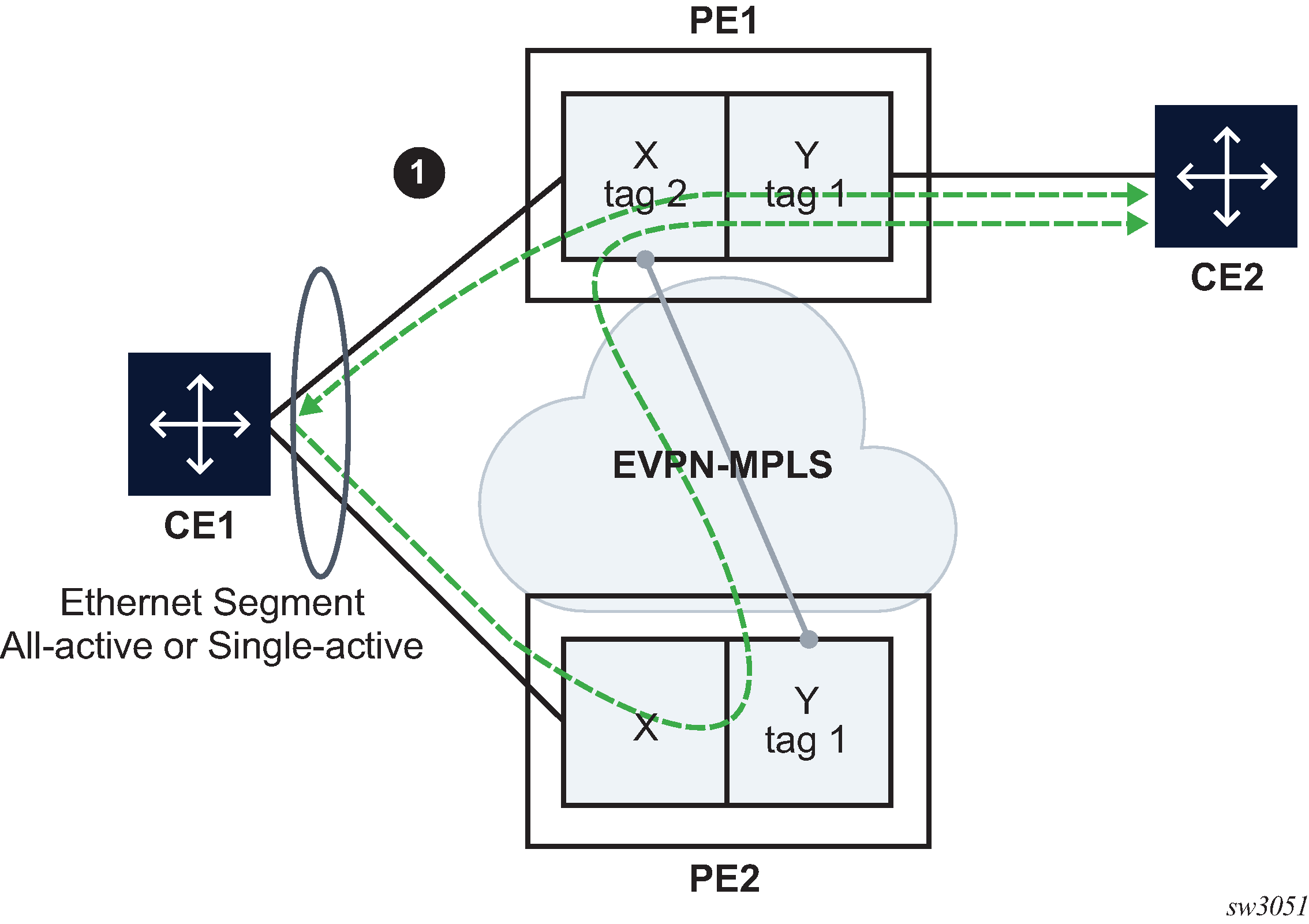
In this example, PE1 is configured with the following Epipe services.
endpoint X create
exit
endpoint Y create
exit
bgp-evpn
  evi 350
  local-attachment-circuit "CE-1" endpoint "Y" create
    eth-tag 1
  exit
  remote-attachment-circuit "ICB-1" endpoint "Y" create
    eth-tag 2
  exit
  local-attachment-circuit "CE-2" endpoint "X" create
    eth-tag 2
  exit
  remote-attachment-circuit "ICB-2" endpoint "X" create
    eth-tag 1
  exit
  mpls bgp 1
    auto-bind-tunnel
      resolution any
      exit
    no shutdown
    exit
  exit
sap lag-1:1 endpoint X create
exit
sap 1/1/1:1 endpoint Y create
exit
PE2 is configured with the following Epipe services.
bgp-evpn
  evi 350
  local-attachment-circuit "CE-1" create
    eth-tag 1
  exit
  remote-attachment-circuit "ICB-1" create
    eth-tag 2
  exit
// implicit endpoint "Y"
  mpls bgp 1
    auto-bind-tunnel
  resolution any
  exit
no shutdown
exit
  exit
sap lag-1:1 create
exit
// implicit endpoint "X"
In this example, if we assume multihoming on CE1, the following applies:
-
PE1 advertises two AD per-EVI routes, for tags 1 and 2, respectively. PE2 advertises only the route for tag 1.
-
AD per-EVI routes for tag 1 are advertised based on CE1 SAPs' states
-
AD per-EVI route for tag 2 is advertised based on CE2 SAP state
-
-
PE1 creates endpoint X with sap lag-1:1 and ES-destination to tag 1 in PE2
-
PE2 creates the usual destination to tag 2 in PE1
-
In case of all-active MH:
-
traffic from CE1 to PE1 is forwarded to CE2 directly
-
traffic from CE1 to PE2 is forwarded to PE1 with the label that identifies CE2's SAP
-
traffic from CE2 is forwarded to CE1 directly because CE1's SAP is the endpoint Tx; in case of failure on CE1's SAP, PE1 changes the Tx object to the ES-destination to PE2
-
-
In case of single-active MH, traffic flows in the same way, except that a non-DF SAP is operationally down and therefore cannot be an endpoint Tx object.
EVPN-VPWS endpoints example 2
The following figure shows an example of EVPN-VPWS endpoints.
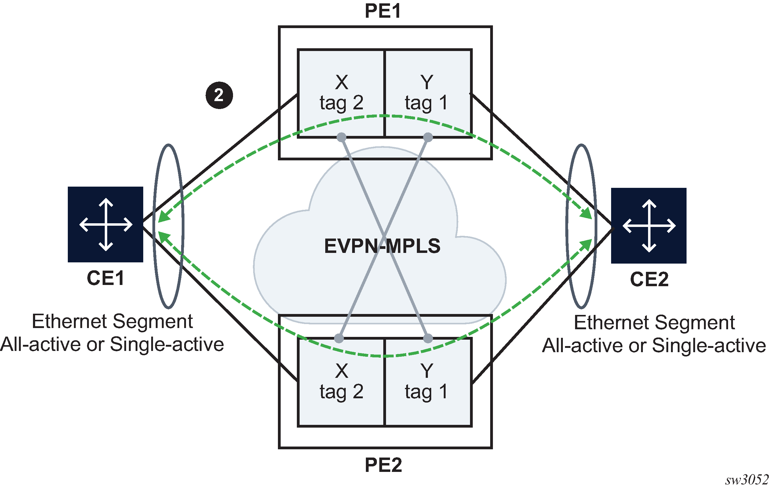
In this example, PE1 is configured with the following Epipe services.
endpoint X create
exit
endpoint Y create
exit
bgp-evpn
  evi 350
  local-attachment-circuit "CE-1" endpoint "Y" create
    eth-tag 1
  exit
  remote-attachment-circuit "ICB-1" endpoint "Y" create
    eth-tag 2
  exit
  local-attachment-circuit "CE-2" endpoint "X" create
    eth-tag 2
  exit
  remote-attachment-circuit "ICB-2" endpoint "X" create
    eth-tag 1
  exit
  mpls bgp 1
    auto-bind-tunnel
      resolution any
      exit
    no shutdown
    exit
  exit
sap lag-1:1 endpoint X create
exit
sap lag-2:1 endpoint Y create
exit
PE2 is configured with the following Epipe services.
endpoint X create
exit
endpoint Y create
exit
bgp-evpn
  evi 350
  local-attachment-circuit "CE-1" endpoint "Y" create
    eth-tag 1
  exit
  remote-attachment-circuit "ICB-1" endpoint "Y" create
    eth-tag 2
  exit
  local-attachment-circuit "CE-2" endpoint "X" create
    eth-tag 2
  exit
  remote-attachment-circuit "ICB-2" endpoint "X" create
    eth-tag 1
  exit
  mpls bgp 1
    auto-bind-tunnel
      resolution any
      exit
    no shutdown
    exit
  exit
sap lag-1:1 endpoint X create
exit
sap lag-2:1 endpoint Y create
exit
This example is similar to the EVPN-VPWS endpoints example 1 example, except that the two PEs are multihomed to both CEs. In EVPN-VPWS endpoints example 1, if CE2 goes down, then no traffic exists between PEs, because the two PEs lose all the objects in the endpoint connected to CE2. Traffic that arrives on EVPN is only forwarded to a SAP on a different endpoint.
EVPN-VPWS endpoints example 3
The following figure shows an example of EVPN-VPWS endpoints.
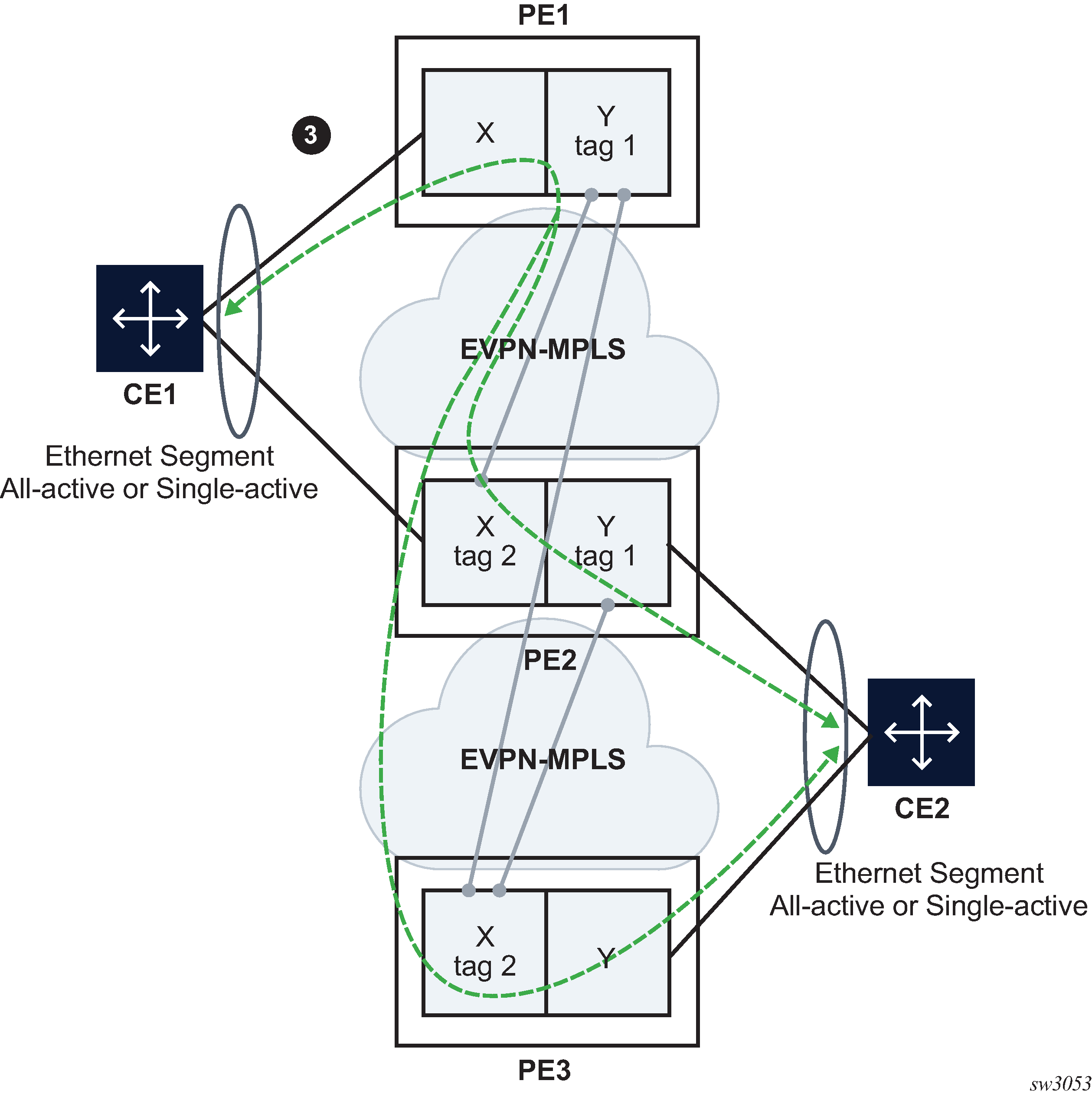
In this example, PE1 is configured with the following Epipe services.
bgp-evpn
  evi 350
  local-attachment-circuit "CE-1"
    eth-tag 1
  exit
  remote-attachment-circuit "ICB-1"
    eth-tag 2
  exit
// implicit endpoint "Y"
  mpls bgp 1
    auto-bind-tunnel
      resolution any
      exit
    no shutdown
    exit
  exit
sap lag-1:1 create
// implicit endpoint "X"
exit
PE2 is configured with the following Epipe services.
endpoint X create
exit
endpoint Y create
exit
bgp-evpn
  evi 350
  local-attachment-circuit "CE-1" endpoint "Y"
    eth-tag 1
  exit
  remote-attachment-circuit "ICB-1" endpoint "Y"
    eth-tag 2
  exit
  local-attachment-circuit "CE-2" endpoint "X"
    eth-tag 2
  exit
  remote-attachment-circuit "ICB-2" endpoint "X"
    eth-tag 1
  exit
  mpls bgp 1
    auto-bind-tunnel
      resolution any
      exit
    no shutdown
    exit
  exit
sap lag-1:1 endpoint X create
exit
sap lag-2:1 endpoint Y create
exit
PE3 is configured with the following Epipe services.
bgp-evpn
  evi 350
  local-attachment-circuit "CE-2"
    eth-tag 2
  exit
  remote-attachment-circuit "ICB-2"
    eth-tag 1
  exit
// implicit endpoint "X"
  mpls bgp 1
    auto-bind-tunnel
      resolution any
      exit
    no shutdown
    exit
  exit
sap lag-1:1 create
// implicit endpoint "Y"
exit
This example is similar to the EVPN-VPWS endpoints example 2 example, except that a third node is added. Nodes PE1 and PE3 have implicit endpoints. Only node PE2 requires the configuration of endpoints.
EVPN-VPWS FXC
FXC, specified in draft-ietf-bess-evpn-vpws-fxc, extends EVPN-VPWS services to support multiple SAPs at the access, in contrast with only one SAP in regular EVPN-VPWS services. Multiplexing multiple SAPs into a single EVPN-VPWS tunnel allows the user to save MPLS labels and reduce the number of EVPN Auto-Discovery per EVI routes.
Use the following command to turn an Epipe into a FXC service.
- MD-CLI
configure service epipe flexible-cross-connect true - classic
CLI
configure service epipe flexible-cross-connect create
Since there are multiple active egress SAPs in FXC services, EVPN labels are no longer enough to identify the egress SAP on the egress node. Therefore, payload VLAN tags are transmitted into EVPN-encapsulated FXC packets, and the router looks up these inner VLAN tags to forward the decapsulated traffic to the correct egress SAP.
configure service epipe sap qtag-normalizationVLAN normalization configuration and the two FXC modes of operation (default and VLAN aware mode) are described in FXC VLAN normalization, Default FXC mode, and VLAN-aware bundle FXC mode.
FXC VLAN normalization
Normalization is a key concept in EVPN-VPWS FXC services and refers to the process of making the SAP VLAN tags unique on the ingress FXC PE. The normalized VLAN tags are sent on the wire in EVPN packets so the egress PE can forward traffic to the correct egress SAP.
The FXC PEs build a table with <normalized-tags, sap> entries per service. An ILM lookup on the service label is performed first, which also indicates whether one or two tags are needed for the egress VLAN lookup (depending on the normalization mode supported by the egress SAP). The table is then looked up to find the egress SAP.
Use the following commands in the configure service epipe context to derive the normalized tags for a SAP:
- MD-CLI
sap qtag-normalization single-tag tag sap qtag-normalization double-tag s-tag sap qtag-normalization double-tag c-tag - classic
CLI
sap qtag-normalization tag create
sap qtag-normalization s-tag.c-tag create
Where:
-
The VLAN behavior adheres to the following rules:
-
Service-delimiting tags are popped at SAP ingress and pushed at SAP egress as usual.
-
When encapsulating into EVPN, service-delimiting tags are translated into normalized VLAN tags and pushed into the EVPN packet.
-
The number of tags pushed on or popped from EVPN packets depends on whether single-tag normalization (one tag pushed/popped) or double-tag normalization (two tags pushed/popped) is configured.
-
-
There is no dependency between the SAP type (null, dot1q, or qinq) and the normalization mode. A null, qinq, or dot1q SAP can be configured with single or double normalization mode.
-
Normalized tags are also used for encoding the Ethernet Tag ID in the AD per-EVI route (in VLAN-aware FXC mode) as s-tag.c-tag (double-tag normalization) or tag (single-tag normalization), where:
-
in single-tag normalization mode, the tag takes the right-most 12 bits of the Ethernet Tag ID
-
in double-tag normalization mode, the S-tag value takes the left-most 12 bits and the C-tag takes the right-most 12 bits
-
-
If no normalized mode is configured, the mode and normalized tag values are derived from the service-delimiting tags, if possible. If the SAP does have service-delimiting tags, configuration of the normalization mode and tags is optional, provided that the number of service-delimiting tags matches the normalization mode.
-
For example, if the SAP ID is 1/1/1:10 but the configured normalization is double-tag, the s-tag and c-tag values must be configured.
-
For SAPs that do not have service-delimiting tags, configuration of the normalization mode and tags is mandatory. The SAPs with no service-delimiting tags are:
-
Null
-
Dot1q:
-
1/1/1:*
-
1/1/1:0
-
1/1/1:cp-1
-
-
Qinq
-
1/1/1:0.*
-
1/1/1:*.*
-
1/1/1:*.null
-
1/1/1:null.null
-
1/1/1:cp-1.*
-
1/1/1:cp-1.0
-
-
-
The following is an example of Q-tag normalization of a double-tag with s-tag=100 and c-tag=200 configuration.
MD-CLI
*[ex:/configure service epipe "1"]
A:admin@PE-1# info
    sap 1/1/c1/1:10.20 {
        qtag-normalization {
            double-tag {
                s-tag 100
                c-tag 200
            }
        }
    }
classic CLI
A:node-2>config>service>epipe# info
----------------------------------------------
sap 1/1/c1/1:10.20 qtag-normalization 100.200 create
The following is an example of Q-tag normalization of a single-tag with a tag=300 configuration.
MD-CLI
[ex:/configure service epipe "1"]
A:admin@node-2# info
    sap 1/1/c1/1:300.400 {
        qtag-normalization {
            single-tag {
                tag 300
            }
        }
    }
classic CLI
A:node-2>config>service>epipe# info
----------------------------------------------
sap 1/1/c1/1:300.400 qtag-normalization 300 create
The following is an example of Q-tag normalization of a double-tag with s-tag=10 and c-tag=0 for two tag configuration.
MD-CLI
[ex:/configure service epipe "1"]
A:admin@node-2# info
    flexible-cross-connect true
    sap 1/1/c1/1:10 {
        qtag-normalization {
            double-tag {
                s-tag 10
                c-tag 0
            }
        }
    }
classic CLI
A:node-2>config>service>epipe# info
----------------------------------------------
sap 1/1/c1/1:10 qtag-normalization 10.0 create
In the following examples, the normalization mode is not configured but derived from the service-delimiting tag.
The following is an example of a normalized s-tag.c-tag (10.20) with a double-tag mode.
MD-CLI
[ex:/configure service epipe "1"]
A:admin@node-2# info
    flexible-cross-connect true
    sap 1/1/c1/1:10.20 {
    }
classic CLI
A:node-2>config>service>epipe# info
----------------------------------------------
sap 1/1/c1/1:10.20 create
The following is an example of a normalized tag (10) and the implicit normalization mode is single-tag.
MD-CLI
[ex:/configure service epipe "1"]
A:admin@node-2# info
    flexible-cross-connect true
    sap 1/1/c1/1:10 {
    }

[ex:/configure service epipe "2"]
A:admin@node-2# info
    flexible-cross-connect true
    sap 1/1/c2/1:10.0 {
    }

[ex:/configure service epipe "3"]
A:admin@node-2# info
    flexible-cross-connect true
    sap 1/1/c3/1:10.* {
    }

[ex:/configure service epipe "4"]
A:admin@node-2# info
    flexible-cross-connect true
    sap 1/1/c4/1:10.cp-1 {
    }
classic CLI
A:node-2>config>service>epipe# info
----------------------------------------------
sap 1/1/c1/1:10 create

A:node-2>config>service>epipe# info
----------------------------------------------
sap 1/1/c1/1:10.0 create

A:node-2>config>service>epipe# info
----------------------------------------------
sap 1/1/c1/1:10.* create

A:node-2>config>service>epipe# info
----------------------------------------------
sap 1/1/c1/1:10.cp-1 create
The following is an example showing the necessity of normalization mode and tags when there are no service-delimiting tags.
MD-CLI
[ex:/configure service epipe "1"]
A:admin@node-2# info
    flexible-cross-connect true
    sap 1/1/c1/1 {
        qtag-normalization {
            single-tag {
                tag 100
            }
        }
    }
classic CLI
A:node-2>config>service>epipe# info
----------------------------------------------
sap 1/1/c1/1 qtag-normalization 100 create
Default FXC mode
SR OS supports the default FXC mode defined in draft-ietf-bess-evpn-vpws-fxc. Use the following command to enable the default mode:
- MD-
CLI
configure service epipe flexible-cross-connect true - classic
CLI
configure service epipe flexible-cross-connect
This command allows the user to configure multiple active SAPs and BGP-EVPN MPLS in the same Epipe service. From the perspective of EVPN, a local and remote Ethernet tag must be configured and, therefore, a single EVPN label is allocated per FXC. The default FXC mode is displayed in the following figure.
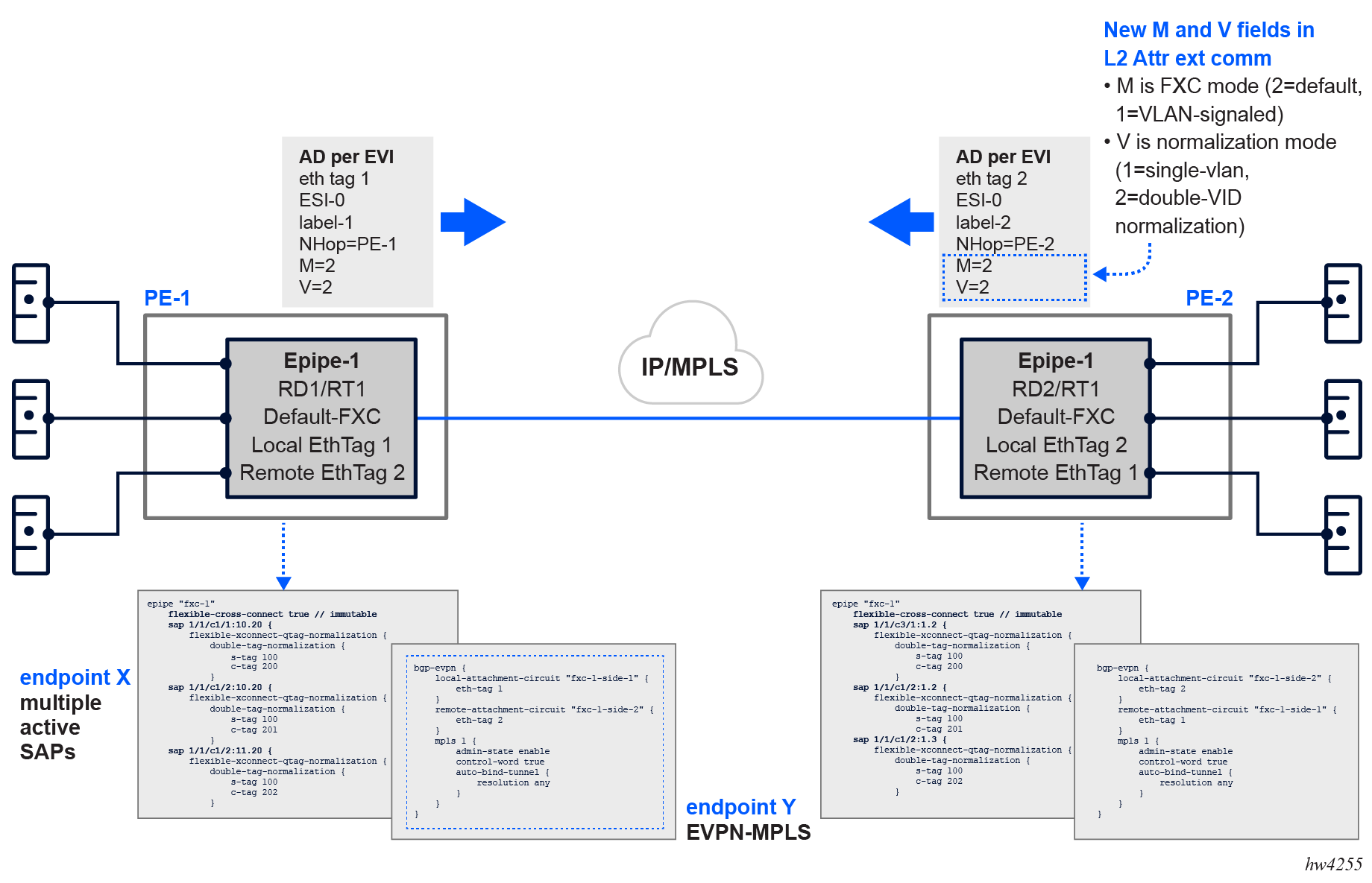
The AD per-EVI route advertised for the FXC default mode service contains two additional flags (compared to the route for regular Epipes):
-
M-flag, with value 2, indicating the FXC default mode
-
V-flag, which indicates the qtag-normalization mode. A value of 1 indicates single-tag normalization, while a value of 2 indicates double-tag normalization.
The following is an example of FXC mode.
MD-CLI
[ex:/configure service epipe "fxc-1"]
A:admin@node-2# info
    flexible-cross-connect true // immutable
    bgp 1 {
    }
    sap 1/1/c1/1:10.20 {
        qtag-normalization {
            double-tag {
                c-tag 200
                s-tag 100
            }
        }
    }
    sap 1/1/c2/1:10.20 {
        qtag-normalization {
            double-tag {
                c-tag 201
                s-tag 101
            }
        }
    }
    sap 1/1/c2/1:11.20 {
        qtag-normalization {
            double-tag {
                c-tag 202
                s-tag 102
            }
        }
    }
    bgp-evpn {
        local-attachment-circuit "fxc-1-side-1" {
            eth-tag 1
        }
        remote-attachment-circuit "fxc-1-side-2" {
            eth-tag 2
        }
        mpls 1 {
            admin-state enable
            control-word true
            auto-bind-tunnel {
                resolution any
            }
        }
    }
classic CLI
A:node-2>config>service>epipe# info
----------------------------------------------
            bgp-evpn
                local-attachment-circuit fxc-1-side-1 bgp 1 create
                    eth-tag 1
                exit
                remote-attachment-circuit fxc-1-side-2 bgp 1 create
                    eth-tag 2
                exit
                evi 500
                mpls bgp 1
                    control-word
                    auto-bind-tunnel
                        resolution any
                    exit
                    no shutdown
                exit
            exit
            sap 1/1/c1/1:10.20 qtag-normalization 100.200 create
                no shutdown
            exit
            sap 1/1/c2/1:10.20 qtag-normalization 101.201 create
                no shutdown
            exit
            sap 1/1/c2/1:11.20 qtag-normalization 102.202 create
                no shutdown
            exit
            no shutdown
----------------------------------------------
The following is an example of FXC mode where the remote PE is expected to be configured with the same normalized Q-tags on SAPs that may have the same service-delimiting VLANs as the local PE.
MD-CLI
[ex:/configure service epipe "fxc-1"]
A:admin@node-2# info
    flexible-cross-connect true // immutable
    bgp 1 {
    }
    sap 1/1/c3/1:1.2 {
        qtag-normalization {
            double-tag {
                c-tag 200
                s-tag 100
            }
        }
    }
    sap 1/1/c2/1:1.2 {
        qtag-normalization {
            double-tag {
                c-tag 201
                s-tag 101
            }
        }
    }
    sap 1/1/c2/1:1.3 {
        qtag-normalization {
            double-tag {
                c-tag 202
                s-tag 102
            }
        }
    }
    bgp-evpn {
        evi 1
        local-attachment-circuit "fxc-1-side-2" {
            eth-tag 2
        }
        remote-attachment-circuit "fxc-1-side-1" {
            eth-tag 1
        }
        mpls 1 {
            admin-state enable
            control-word true
            auto-bind-tunnel {
                resolution any
            }
        }
    }
classic CLI
A:node-2>config>service>epipe# info
----------------------------------------------
            bgp-evpn
                local-attachment-circuit fxc-1-side-2 bgp 1 create
                    eth-tag 2
                exit
                remote-attachment-circuit fxc-1-side-1 bgp 1 create
                    eth-tag 1
                exit
                evi 1
                mpls bgp 1
                    control-word
                    auto-bind-tunnel
                        resolution any
                    exit
                    no shutdown
                exit
            exit
            sap 1/1/c3/1:1.2 qtag-normalization 100.200 create
                no shutdown
            exit
            sap 1/1/c2/1:1.2 qtag-normalization 101.201 create
                no shutdown
            exit
            sap 1/1/c2/1:1.3 qtag-normalization 102.202 create
                no shutdown
            exit
            no shutdown
----------------------------------------------
Use the following command to display BGP EVPN-MPLS destination information.
show service id 500 evpn-mpls===============================================================================
BGP EVPN-MPLS Dest (Instance 1)
===============================================================================
TEP Address Egr Label Num Last Change
Transport:Tnl-id Saps
-------------------------------------------------------------------------------
2001:db8::4 524283 2 09/13/2024 16:58:53
ldp:65542
-------------------------------------------------------------------------------
Number of entries : 1
-------------------------------------------------------------------------------
===============================================================================
===============================================================================
BGP EVPN-MPLS Dest (Instance 2)
===============================================================================
TEP Address Egr Label Num Last Change
Transport:Tnl-id Saps
-------------------------------------------------------------------------------
No Matching Entries
===============================================================================
===============================================================================
BGP EVPN-MPLS Ethernet Segment Dest (Instance 1)
===============================================================================
Eth SegId Num Saps Last Change
-------------------------------------------------------------------------------
No Matching Entries
===============================================================================
===============================================================================
BGP EVPN-MPLS Ethernet Segment Dest (Instance 2)
===============================================================================
Eth SegId Num Saps Last Change
-------------------------------------------------------------------------------
No Matching Entries
===============================================================================
Use the following command to display FXC configuration that shows a single EVPN or ES destination (as in regular EVPN-VPWS).
show service id 500 evpn-mpls fxc ===============================================================================
FXC SAP Connections (Instance 1)
===============================================================================
Dest Identifier Sap (Normalized Tags) Last Change
Transport:Tnl-id
-------------------------------------------------------------------------------
mpls-1:2001:db8::4:524283 lag-1:500 (550.550) 09/13/2024
16:58:53
ldp:65542 lag-1:501 (551.551) 09/13/2024
16:58:53
-------------------------------------------------------------------------------
Number of Entries : 1
-------------------------------------------------------------------------------
===============================================================================
While the default FXC mode uses a single label and single EVPN AD per-EVI route per Epipe service, which translates into significant resource savings in the network, an individual SAP going operationally down goes unnoticed. The remote PE continues sending traffic for the down SAP, only to be dropped at the egress PE where the SAP is operationally down.
Consequently, EVPN multihoming is supported only if all SAPs in the FXC belong to the same Ethernet segment (ES). While individual SAP failures are still unnoticed, physical port failures means the entire ES fails and the AD per-EVI and per-ES routes are withdrawn so that the remote PE can switch over to the redundant PE of the ES.
If signaling and fault propagation per SAP is needed in the FXC, the VLAN-aware bundle FXC mode must be configured.
VLAN-aware bundle FXC mode
Use the following commands to enable the VLAN-aware bundle FXC mode:
- MD-CLI
configure service epipe flexible-cross-connect true configure service epipe bgp-evpn local-attachment-circuit vlan-signaled-flexible-cross-connect true - classic
CLI
configure service epipe flexible-cross-connect
configure service epipe flexible-cross-connect local-attachment-circuit vlan-signaled-flexible-cross-connect
When the VLAN-aware bundle FXC mode is enabled, the following rules apply:
-
Two EVPN labels are allocated for the Epipe, one per normalization mode (single- and double-tag normalization).
-
The configuration of local and remote Ethernet tags is blocked; they are automatically derived from the normalized tags for each SAP. For example, suppose two SAPs with normalization 10.20 and 30.40 are configured in the service. This automatically creates a local Ethernet tag 10.20 (and same remote Ethernet tag) and a local Ethernet tag 30.40 (and same Ethernet tag).
-
A separate AD per-EVI route is now advertised per SAP with the automatically generated local Ethernet tags, and flags M=1 (VLAN-signaled FXC) and V=1 or V=2 depending on the normalization type for the SAP.
-
In this mode, traffic from a specific SAP with normalized tags 100.200 is discarded at the ingress PE when there is no AD per-EVI route for tags 100.200 at the Epipe service. The SAP (for which no remote peer matching tags are found) stays operationally up, however, traffic is dropped because there is no destination to send it to. SAP statistics show the discarded ingress packets. In this case, the show service id evpn-mpls fxc command displays the SAP associated with a destination with a value of none.
-
Contrary to the default mode, in VLAN-aware bundle FXC mode, multiple ESs may exist in the same Epipe (with a single SAP per FXC per ES).
The following figure shows the VLAN-aware bundle or VLAN-signaled FXC mode.
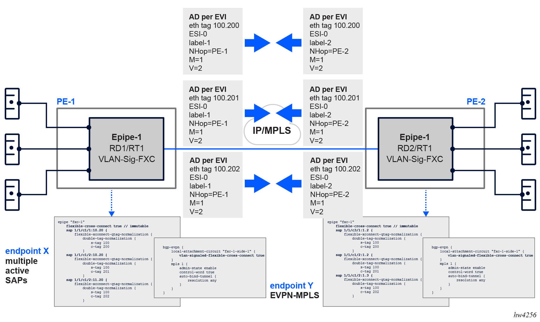
Where node-1 is configured as shown in the following example.
MD-CLI
[ex:/configure service epipe "fxc-1"]
A:admin@node-1# info
    flexible-cross-connect true // immutable
    bgp 1 {
    }
    sap 1/1/c1/1:10.20 {
        qtag-normalization {
            double-tag {
                c-tag 200
                s-tag 100
            }
        }
    }
    sap 1/1/c2/1:10.20 {
        qtag-normalization {
            double-tag {
                c-tag 201
                s-tag 101
            }
        }
    }
    sap 1/1/c2/1:11.20 {
        qtag-normalization {
            double-tag {
                c-tag 202
                s-tag 102
            }
        }
    }
    bgp-evpn {
        evi 1
        local-attachment-circuit "fxc-1-side-1" {
            vlan-signaled-flexible-cross-connect true
        }
        mpls 1 {
            admin-state enable
            control-word true
            auto-bind-tunnel {
                resolution any
            }
        }
    }
classic CLI
A:node-1>config>service>epipe# info
----------------------------------------------
            bgp-evpn
                local-attachment-circuit fxc-1-side-1 bgp 1 create
                    vlan-signaled-flexible-cross-connect
                exit
                evi 1
                mpls bgp 1
                    control-word
                    auto-bind-tunnel
                        resolution any
                    exit
                    no shutdown
                exit
            exit
            sap 1/1/c1/1:10.20 qtag-normalization 100.200 create
                no shutdown
            exit
            sap 1/1/c2/1:10.20 qtag-normalization 101.201 create
                no shutdown
            exit
            sap 1/1/c2/1:11.20 qtag-normalization 102.202 create
                no shutdown
            exit
            no shutdown
----------------------------------------------
Where node-2 in VLAN-aware bundle or VLAN-signaled FXC mode is configured as follows:
MD-CLI
[ex:/configure service epipe "fxc-1"]
A:admin@node-2# info
    flexible-cross-connect true // immutable
    bgp 1 {
    }
    sap 1/1/c3/1:1.2 {
        qtag-normalization {
            double-tag {
                c-tag 200
                s-tag 100
            }
        }
    }
    sap 1/1/c1/1:101.201 {
    }
    sap 1/1/c5/1:102.202 {
    }
    bgp-evpn {
        local-attachment-circuit "fxc-1-side-1" {
            vlan-signaled-flexible-cross-connect true
        }
        mpls 1 {
            admin-state enable
            control-word true
            auto-bind-tunnel {
                resolution any
            }
        }
    }
classic CLI
A:node-2>config>service>epipe# info
----------------------------------------------
            bgp-evpn
                local-attachment-circuit fxc-1-side-1 bgp 1 create
                    vlan-signaled-flexible-cross-connect
                exit
                evi 1
                mpls bgp 1
                    control-word
                    auto-bind-tunnel
                        resolution any
                    exit
                    no shutdown
                exit
            exit
            sap 1/1/c3/1:10.20 qtag-normalization 100.200 create
                no shutdown
            exit
            sap 1/1/c1/1:101.201 create
                no shutdown
            exit
            sap 1/1/c5/1:102.202 create
                no shutdown
            exit
            no shutdown
----------------------------------------------
In the preceding example configuration, if the SAP associated with normalized tags 100.200 on remote node-2 goes down, upon withdrawal of the AD per-EVI route, the local SAP associated with the same normalized tags is also removed from the output. Use the following command to display this information.
show service id 100 evpn-mpls fxc ===============================================================================
FXC SAP Connections (Instance 1)
===============================================================================
Dest Identifier Sap (Normalized Tags) Last Change
Transport:Tnl-id
-------------------------------------------------------------------------------
mpls-1:192.0.2.2:524281 1/1/c1/1:10.20(100.200) 09/13/2024
16:58:53
ldp:65542
mpls-1:192.0.2.2:524281 1/1/c2/1:10.20(101.201) 09/13/2024
16:58:53
ldp:65542
mpls-1:192.0.2.2:524281 1/1/c2/1:11.20(102.202) 09/13/2024
16:58:53
ldp:65542
-------------------------------------------------------------------------------
Number of Entries : 3
-------------------------------------------------------------------------------
===============================================================================
1 2024/09/16 00:26:41.390 UTC MINOR: DEBUG #2001 Base Peer 1: 2001:db8::2
"Peer 1: 2001:db8::2: UPDATE
Peer 1: 2001:db8::2 - Received BGP UPDATE:
Withdrawn Length = 0
Total Path Attr Length = 34
Flag: 0x90 Type: 15 Len: 30 Multiprotocol Unreachable NLRI:
Address Family EVPN
Type: EVPN-AD Len: 25 RD: 192.0.2.2:100 ESI: ESI-0, tag: 409800 Label: 0 (R
aw Label: 0x0) PathId:
"
show service id 100 evpn-mpls fxc ===============================================================================
FXC SAP Connections (Instance 1)
===============================================================================
Dest Identifier Sap (Normalized Tags) Last Change
Transport:Tnl-id
-------------------------------------------------------------------------------
mpls-1:192.0.2.2:524281 1/1/c1/1:10.20(101.201) 09/13/2024
16:58:53
ldp:65542
mpls-1:192.0.2.2:524281 1/1/c2/1:11.20(102.202) 09/13/2024
16:58:53
ldp:65542
-------------------------------------------------------------------------------
Number of Entries : 2
-------------------------------------------------------------------------------
===============================================================================
In addition, using the following command displays new information to identify the normalization mode (indicated in bold):
show service id 4 sap 1/1/c1/1:45 detail ===============================================================================
Service Access Points(SAP)
===============================================================================
Service Id : 4
SAP : 1/1/c1/1:45 Encap : q-tag
Description : (Not Specified)
Admin State : Up Oper State : Up
Flags : None
Multi Svc Site : None
Last Status Change : 04/02/2024 18:08:35
Last Mgmt Change : 04/02/2024 18:08:26
Sub Type : regular
Dot1Q Ethertype : 0x8100 QinQ Ethertype : 0x8100
Split Horizon Group: (Not Specified)
Eth Seg Name : vES-4
Admin MTU : 9208 Oper MTU : 9208
Ingr IP Fltr-Id : n/a Egr IP Fltr-Id : n/a
Ingr Mac Fltr-Id : n/a Egr Mac Fltr-Id : n/a
Ingr IPv6 Fltr-Id : n/a Egr IPv6 Fltr-Id : n/a
qinq-pbit-marking : both
Endpoint : N/A
Egr Agg Rate Limit : max
Q Frame-Based Acct : Disabled Limit Unused BW : Disabled
Vlan-translation : None
Qinq-vlan- Qinq-vlan-
translation : None translation Ids : None
Acct. Pol : None Collect Stats : Disabled
Application Profile: None
Transit Policy : None
Oper Group : og-4 Monitor Oper Grp : (none)
Host Lockout Plcy : n/a
Ignore Oper Down : Disabled
Lag Link Map Prof : (none)
Cflowd : Disabled
Bandwidth : Not-Applicable
Oper DCpu Prot Pol : _default-access-policy
Virtual Port : (Not Specified)
FXC VLAN normalization mode : Double (Tags 9.10)
-------------------------------------------------------------------------------
ETH-CFM SAP specifics
-------------------------------------------------------------------------------
Tunnel Faults : n/a AIS : Disabled
MC Prop-Hold-Timer : n/a
Squelch Levels : None
Squelch Ctag Levels: None
Collect Lmm Stats : Disabled
LMM FC Stats : None
LMM FC In Prof : None
-------------------------------------------------------------------------------
QOS
-------------------------------------------------------------------------------
Ingress qos-policy : 1 Egress qos-policy : 1
Ingress FP QGrp : (none) Egress Port QGrp : (none)
Ing FP QGrp Inst : (none) Egr Port QGrp Inst: (none)
Ing ip-match tag : none Ing ipv6-match tag: none
I. Sched Pol : (Not Specified)
E. Sched Pol : (Not Specified)
I. Policer Ctl Pol : (Not Specified)
E. Policer Ctl Pol : (Not Specified)
I. QGrp Redir. List: (Not Specified)
E. QGrp Redir. List: (Not Specified)
Hw Agg Shaper Q Set: No
Hw Agg Shpr QSet Sz: 0
Hw Agg Shpr In-Use : No
Latency Budget : 0 us
-------------------------------------------------------------------------------
Sap Aggregate Stats
-------------------------------------------------------------------------------
Packets Octets
Ingress
Aggregate Offered : 0 0
Aggregate Forwarded : 0 0
Aggregate Dropped : 0 0
Egress
Aggregate Forwarded : 0 0
Aggregate Dropped : 0 0
-------------------------------------------------------------------------------
Sap Statistics
-------------------------------------------------------------------------------
Last Cleared Time : N/A
Packets Octets
CPM Ingress : 0 0
Forwarding Engine Stats
Dropped : 3 204
Received Valid : 0 0
Off. HiPrio : 0 0
Off. LowPrio : 0 0
Off. Uncolor : 0 0
Off. Managed : 0 0
Queueing Stats(Ingress QoS Policy 1)
Dro. HiPrio : 0 0
Dro. LowPrio : 0 0
For. InProf : 0 0
For. OutProf : 0 0
Queueing Stats(Egress QoS Policy 1)
Dro. In/InplusProf : 0 0
Dro. Out/ExcProf : 0 0
For. In/InplusProf : 0 0
For. Out/ExcProf : 0 0
-------------------------------------------------------------------------------
Sap per Queue stats
-------------------------------------------------------------------------------
Packets Octets
Ingress Queue 1 (Unicast) (Priority)
Off. HiPrio : 0 0
Off. LowPrio : 0 0
Dro. HiPrio : 0 0
Dro. LowPrio : 0 0
For. InProf : 0 0
For. OutProf : 0 0
Egress Queue 1
For. In/InplusProf : 0 0
For. Out/ExcProf : 0 0
Dro. In/InplusProf : 0 0
Dro. Out/ExcProf : 0 0
===============================================================================
Use the following command to display all the SAPs and their EVPN destinations.
show service id 100 evpn-mpls===============================================================================
BGP EVPN-MPLS Dest (Instance 1)
===============================================================================
TEP Address Egr Label Num Saps Last Change
Transport:Tnl-id
-------------------------------------------------------------------------------
10.20.1.2 524285 3 08/15/2023 23:18:50
ldp:65543
10.20.1.2 524286 2 08/15/2023 23:18:50
ldp:65543
10.20.1.3 524285 1 08/15/2023 23:18:50
ldp:50000
-------------------------------------------------------------------------------
Number of entries : 3
===============================================================================
===============================================================================
BGP EVPN-MPLS Ethernet Segment Dest (Instance 1)
===============================================================================
Eth SegId Num Saps Last Change
-------------------------------------------------------------------------------
00:00:11:11:00:00:11:11:11:11 1 08/15/2023 23:18:50
00:00:11:11:00:00:11:11:22:22 1 08/15/2023 23:18:50
-----------------------------------------------------------------------------------
Number of entries : 2
===============================================================================
Use the following command to display all the FXC EVPN-MPLS connections.
show service id 100 evpn-mpls fxc===============================================================================
FXC EVPN-MPLS Connections
===============================================================================
Dest Identifier Sap (Normalized Tags) Last Change
Transport:Tnl-id
-------------------------------------------------------------------------------
mpls-1:10.20.1.2:524285 1/1/c1/1:5.6 (2.2) 08/15/2023 23:18:50
ldp:65543 lag-6:100 (3.4) 08/15/2023 23:18:50
1/1/c2/2:*.0 (100.1) 08/15/2023 23:18:50
mpls-1:10.20.1.2:524286 1/1/c2/3:1 (1) 08/15/2023 23:18:50
ldp:65543 lag-6:101 (101) 08/15/2023 23:18:50
mpls-1:10.20.1.3:524285 1/1/c2/3:2 (2) 08/15/2023 23:18:50
ldp:50000
eES:00:00:11:11:00:00:11:11:11:11 lag-6:200 (500) 08/15/2023 23:18:50
eES:00:00:11:11:00:00:11:11:22:22 lag-6:2.2 (2.2) 08/15/2023 23:18:50
-------------------------------------------------------------------------------
Number of entries : 5
-------------------------------------------------------------------------------
===============================================================================
Use the following command to display all the FXC EVPN-MPLS connections for a specific SAP.
show service id 100 evpn-mpls fxc sap 1/1/c1/1:5.6===============================================================================
FXC EVPN-MPLS Connections
===============================================================================
Dest Identifier Sap (Normalized Tags) Last Change
Transport:Tnl-id
-------------------------------------------------------------------------------
mpls-1:10.20.1.2:524285 1/1/c1/1:5.6 (2.2) 08/15/2023 23:18:50
ldp:65543
EVPN for MPLS tunnels in routed VPLS services
EVPN-MPLS and IP-prefix advertisement (enabled by the ip-route-advertisement command) are fully supported in routed VPLS services and provide the same feature-set as EVPN-VXLAN. The following capabilities are supported in a service where bgp-evpn mpls is enabled:
R-VPLS with VRRP support on the VPRN or IES interfaces
R-VPLS support including ip-route-advertisement with regular interfaces
This includes the advertisement and process of ip-prefix routes defined in IETF Draft draft-ietf-bess-evpn-prefix-advertisement with the appropriate encoding for EVPN-MPLS.
R-VPLS support including ip-route-advertisement with evpn-tunnel interfaces
R-VPLS with IPv6 support on the VPRN or IES IP interface
IES interfaces do not support either ip-route-advertisement or evpn-tunnel.
EVPN-MPLS multihoming and passive VRRP
SAP and spoke-SDP based ESs are supported on R-VPLS services where bgp-evpn mpls is enabled.
EVPN-MPLS multihoming in R-VPLS services shows an example of EVPN-MPLS multihoming in R-VPLS services, with the following assumptions:
-
There are two subnets for a specific customer (for example, EVI1 and EVI2 in EVPN-MPLS multihoming in R-VPLS services), and a VPRN is instantiated in all the PEs for efficient inter-subnet forwarding.
-
A ‟backhaul” R-VPLS with evpn-tunnel mode enabled is used in the core to interconnect all the VPRNs. EVPN IP-prefix routes are used to exchange the prefixes corresponding to the two subnets.
-
An all-active ES is configured for EVI1 on PE1 and PE2.
-
A single-active ES is configured for EVI2 on PE3 and PE4.
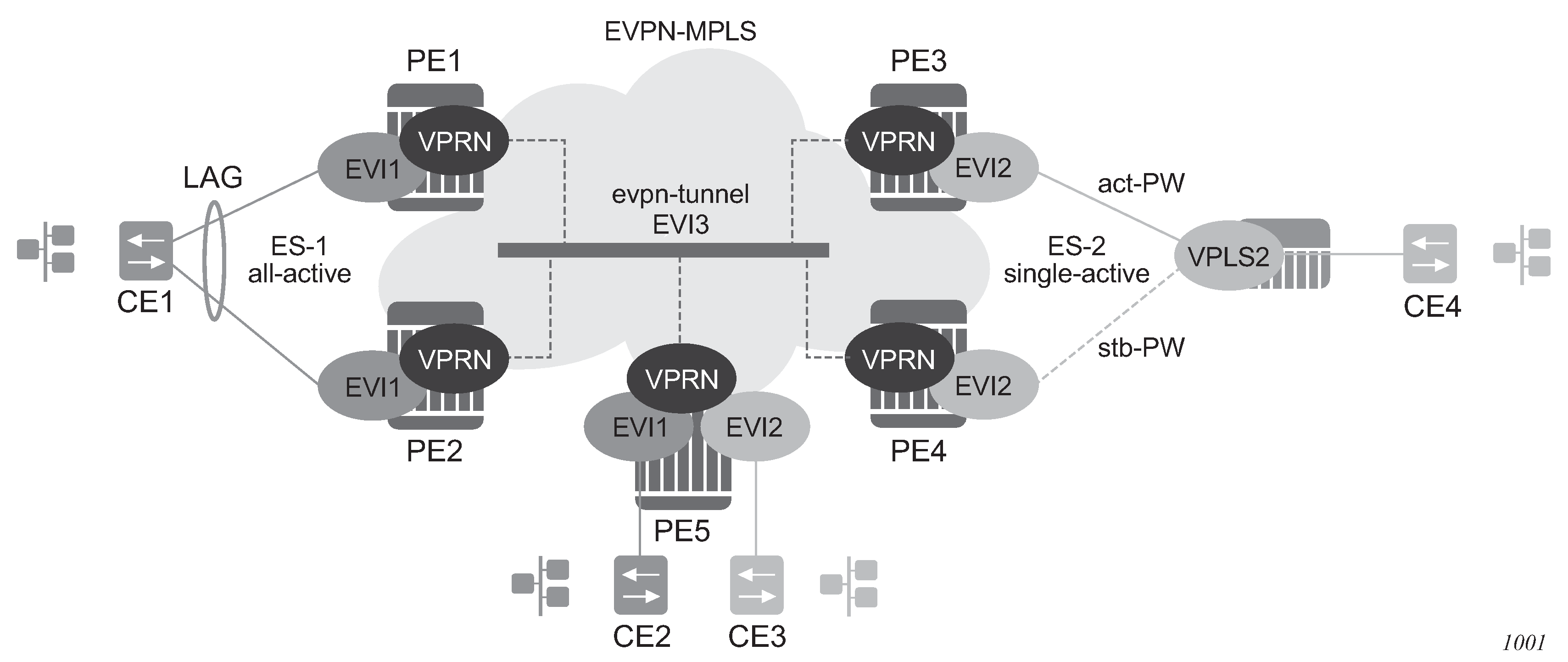
In the example in the preceding figure, the hosts connected to CE1 and CE4 can use regular VRRP for default gateway redundancy; however, this may not be the most efficient way to provide upstream routing.
For example, if PE1 and PE2 are using regular VRRP, the upstream traffic from CE1 may be hashed to the backup IRB VRRP interface, instead of being hashed to the master. The same may occur for single-active multihoming and regular VRRP for PE3 and PE4. The traffic from CE4 is sent to PE3, when PE4 may be the VRRP master. In that case, PE3 must send the traffic to PE4, instead of routing it directly.
Both cases use unnecessary bandwidth between the PEs to get to the master IRB interface. In addition, VRRP scaling is limited if aggressive keepalive timers are used.
Because of these issues, passive VRRP is the recommended method when EVPN-MPLS multihoming is used in combination with R-VPLS redundant interfaces.
Passive VRRP is a VRRP setting in which the transmission and reception of keepalive messages is completely suppressed, and therefore, the VPRN interface always behaves as the master. Passive VRRP is enabled by adding the passive keyword to the VRRP instance at creation, as shown in the following examples:
configure service vprn 1 interface int-1 vrrp 1 passiveconfigure service vprn 1 interface int-1 ipv6 vrrp 1 passiveFor example, if PE1, PE2, and PE5 in EVPN-MPLS multihoming in R-VPLS services use passive VRRP, even if each individual R-VPLS interface has a different MAC/IP address, because they share the same VRRP instance 1 and the same backup IP, the three PEs will own the same virtual MAC and virtual IP address (for example, 00-00-5E-00-00-01 and 10.0.0.254). The virtual MAC is auto-derived from 00-00-5E-00-00-VRID per RFC 3768. The following is the expected behavior when passive VRRP is used in this example:
-
All R-VPLS IRB interfaces for EVI1 have their own physical MAC/IP address; they also own the same default gateway virtual MAC and IP address.
-
All EVI1 hosts have a unique configured default gateway; for example, 10.0.0.254.
-
When CE1 or CE2 send upstream traffic to a remote subnet, the packets are routed by the closest PE because the virtual MAC is always local to the PE.
For example, the packets from CE1 hashed to PE1 are routed at PE1. The packets from CE1 hashed to PE2 are routed directly at PE2.
-
Downstream packets (for example, packets from CE3 to CE1), are routed directly by the PE to CE1, regardless of the PE to which PE5 routed the packets.
For example, the packets from CE3 sent to PE1 are routed at PE1. The packets from CE3 sent to PE2 are routed at PE2.
-
In case of ES failure in one of the PEs, the traffic is forwarded by the available PE.
For example, if the packets routed by PE5 arrive at PE1 and the link to CE1 is down, PE1 sends the packets to PE2. PE2 forwards the packets to CE1 even if the MAC source address of the packets matches PE2's virtual MAC address. Virtual MACs bypass the R-VPLS interface MAC protection.
The following list summarizes the advantages of using passive VRRP mode versus regular VRRP for EVPN-MPLS multihoming in R-VPLS services:
-
Passive VRRP does not require multiple VRRP instances to achieve default gateway load-balancing. Only one instance per R-VPLS, therefore only one default gateway, is needed for all the hosts.
-
The convergence time for link/node failures is not impacted by the VRRP convergence, because all the nodes in the VRRP instance are master routers.
-
Passive VRRP scales better than VRRP, as it does not use keepalive or BFD messages to detect failures and allow the backup to take over.
In EVPN all-active multi-homing scenarios with R-VPLS services where the advertisement of the ARP/ND entries is enabled, use the following command to avoid issues with MAC mobility caused by the MAC/IP advertisement route for the ARP/ND entry being sent with ESI=0:
- MD-CLI
configure service vpls bgp-evpn routes mac-ip arp-nd-only-with-fdb-advertisement true - classic
CLI
configure service vpls bgp-evpn arp-nd-only-with-fdb-advertisement
When this command is enabled, the local ARP/ND entries of VPRN interfaces using this VPLS are advertised in this BGP-EVPN service only when the corresponding local MAC is programmed in the FDB.
In an EVPN multi-homing scenario, this command prevents the router from advertising a MAC/IP advertisement route with the MAC and IP binding but without the correct ESI value (which is taken only when the MAC is properly programmed in the FDB against the ESI).
In addition, if an Ethernet Segment SAP receives a frame, the MAC address can be re-programmed as type learned, even if the MAC was previously programmed as type EVPN.
EVPN-MPLS routed VPLS multicast routing support
In an EVPN-MPLS VPRN routed VPLS, IPv4 multicast routing is supported through its IP interface, when the source of the multicast stream is on one side of its IP interface and the receivers are on either side of the IP interface. For example, the source for multicast stream G1 could be on the IP side sending to receivers on both other regular IP interfaces and the VPLS of the routed VPLS service, while the source for group G2 could be on the VPLS side sending to receivers on both the VPLS and IP side of the routed VPLS service.
See IPv4 and IPv6 multicast routing support for more information.
IGMP snooping in EVPN-MPLS
IGMP snooping is supported in EVPN-MPLS VPLS services. It is also supported in EVPN-MPLS VPRN and IES R-VPLS services. It is required in scenarios where the operator does not want to flood all of the IP multicast traffic to the access nodes or CEs, and only wants to deliver IP multicast traffic for which IGMP reports have been received.
The following points apply when IGMP snooping is configured in EVPN-MPLS VPLS services:
IGMP snooping is enabled using the configure service vpls igmp-snooping no shutdown command.
Queries and reports received on SAP or SDP bindings are snooped and properly handled; they are sent to SAP or SDP bindings as expected.
Queries and reports on EVPN-MPLS destinations are handled as follows.
If received from SAP or SDP bindings, the queries and reports are sent to all EVPN-MPLS destinations, regardless of whether the service is using an ingress replication or mLDP provider tunnel.
If received on an EVPN-MPLS destination, the queries and reports are processed and propagated to access SAP or SDP bindings, regardless of whether the service is using an ingress replication or mLDP provider tunnel.
EVPN-MPLS destinations are is treated as a single IGMP snooping interface and is always added as an mrouter.
The debug trace output displays one copy of messages being sent to all EVPN-MPLS destinations (the trace does not show a copy for each destination) and displays messages received from all EVPN-MPLS destinations as coming from a single EVPN-MPLS interface.
In the following show command output, the EVPN-MPLS destinations are shown as part of the MFIB (when igmp-snooping is in a no shutdown state), and the EVPN-MPLS logical interface is shown as an mrouter.
*A:PE-2# show service id 2000 mfib
===============================================================================
Multicast FIB, Service 2000
===============================================================================
Source Address  Group Address         SAP or SDP Id                   Svc Id   Fwd
                                                                            Blk
-------------------------------------------------------------------------------
*               *                     eMpls:192.0.2.3:262132       Local    Fwd
                                      eMpls:192.0.2.4:262136       Local    Fwd
                                      eMpls:192.0.2.5:262131       Local    Fwd
-------------------------------------------------------------------------------
Number of entries: 1
===============================================================================
*A:PE-2# show service id 2000 igmp-snooping base
===============================================================================
IGMP Snooping Base info for service 2000
===============================================================================
Admin State : Up
Querier     : 10.0.0.3 on evpn-mpls
-------------------------------------------------------------------------------
SAP or SDP                   Oper MRtr Pim  Send Max   Max  Max   MVR       Num
Id                        Stat Port Port Qrys Grps  Srcs Grp   From-VPLS Grps
                                                         Srcs
-------------------------------------------------------------------------------
sap:1/1/1:2000            Up   No   No   No   None  None None  Local     0
evpn-mpls                 Up   Yes  N/A  N/A  N/A   N/A  N/A   N/A       N/A
===============================================================================


*A:PE-4# show service id 2000 igmp-snooping mrouters

===============================================================================
IGMP Snooping Multicast Routers for service 2000
===============================================================================
MRouter          SAP or SDP Id                 Up Time        Expires   Version
-------------------------------------------------------------------------------
10.0.0.3         evpn-mpls                  0d 00:38:49    175s      3
-------------------------------------------------------------------------------
Number of mrouters: 1
===============================================================================
Data-driven IGMP snooping synchronization with EVPN multihoming
When single-active multihoming is used, the IGMP snooping state is learned on the active multihoming object. If a failover occurs, the system with the newly active multihoming object must wait for IGMP messages to be received to instantiate the IGMP snooping state after the ES activation timer expires; this could result in an increased outage.
The outage can be reduced by using MCS synchronization, which is supported for IGMP snooping in both EVPN-MPLS and PBB-EVPN services (see Multichassis synchronization for Layer 2 snooping states). However, MCS only supports synchronization between two PEs, whereas EVPN multihoming is supported between a maximum of four PEs. Also, IGMP snooping state can be synchronized only on a SAP.
An increased outage would also occur when using all-active EVPN multihoming. The IGMP snooping state on an ES LAG SAP or virtual ES to the attached CE must be synchronized between all the ES PEs, as the LAG link used by the DF PE may not be the same as that used by the attached CE. MCS synchronization is not applicable to all-active multihoming as MCS only supports active/standby synchronization.
To eliminate any additional outage on a multihoming failover, IGMP snooping messages can be synchronized between the PEs on an ES using data-driven IGMP snooping state synchronization, which is supported in EVPN-MPLS services, PBB-EVPN services, EVPN-MPLS VPRN and IES R-VPLS services. The IGMP messages received on an ES SAP or spoke SDP are sent to the peer ES PEs with an ESI label (for EVPN-MPLS) or ES B-MAC (for PBB-EVPN) and these are used to synchronize the IGMP snooping state on the ES SAP or spoke SDP on the receiving PE.
Data-driven IGMP snooping state synchronization is supported for both all-active multihoming and single-active with an ESI label multihoming in EVPN-MPLS, EVPN-MPLS VPRN and IES R-VPLS services, and for all-active multihoming in PBB-EVPN services. All PEs participating in a multihomed ES must be running an SR OS version supporting this capability. PBB-EVPN with IGMP snooping using single-active multihoming is not supported.
Data-driven IGMP snooping state synchronization is also supported with P2MP mLDP LSPs in both EVPN-MPLS and PBB-EVPN services. When P2MP mLDP LSPs are used in EVPN-MPLS services, all PEs (including the PEs not connected to a multihomed ES) in the EVPN-MPLS service must be running an SR OS version supporting this capability with IGMP snooping enabled and all network interfaces must be configured on FP3 or higher-based line cards.
Data-driven IGMP snooping synchronization with EVPN multihoming shows the processing of an IGMP message for EVPN-MPLS. In PBB-EVPN services, the ES B-MAC is used instead of the ESI label to synchronize the state.
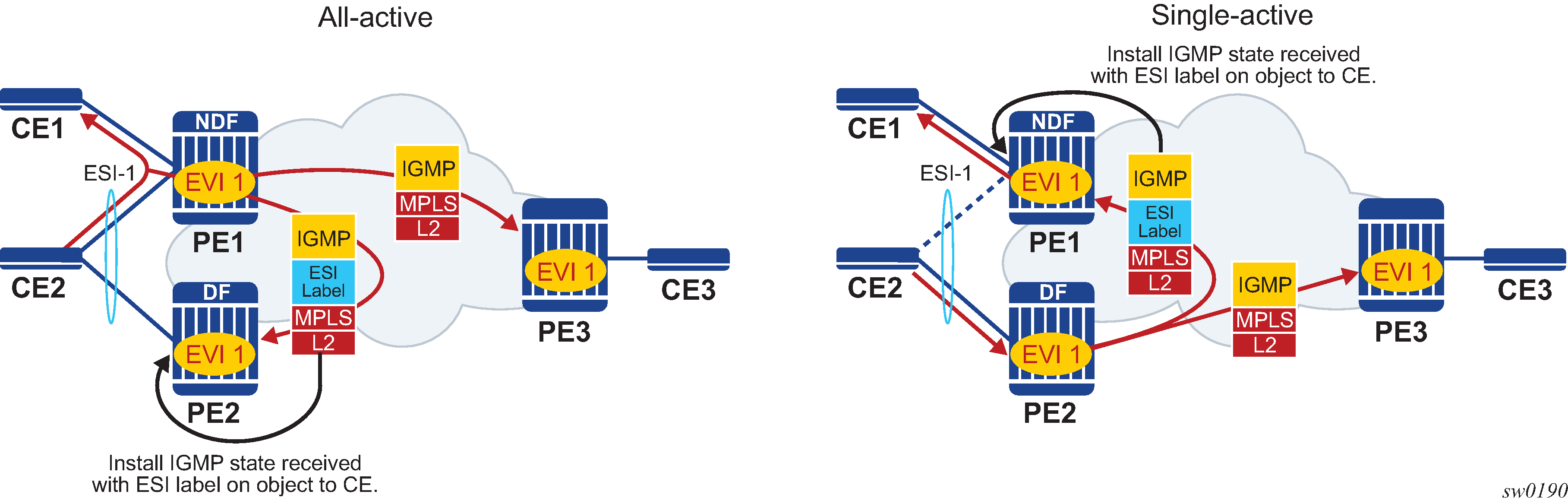
Data-driven synchronization is enabled by default when IGMP snooping is enabled within an EVPN-MPLS service using all-active multihoming or single-active with an ESI label multihoming, or in a PBB-EVPN service using all-active multihoming. If IGMP snooping MCS synchronization is enabled on an EVPN-MPLS or PBB-EVPN (I-VPLS) multihoming SAP then MCS synchronization takes precedence over the data-driven synchronization and the MCS information is used. Mixing data-driven and MCS IGMP synchronization within the same ES is not supported.
When using EVPN-MPLS, the ES should be configured as non-revertive to avoid an outage when a PE takes over the DF role. The Ethernet A-D per ESI route update is withdrawn when the ES is down which prevents state synchronization to the PE with the ES down, as it does not advertise an ESI label. The lack of state synchronization means that if the ES comes up and that PE becomes DF after the ES activation timer expires, it may not have any IGMP snooping state until the next IGMP messages are received, potentially resulting in an additional outage. Configuring the ES as non-revertive can avoid this potential outage. Configuring the ES to be non-revertive would also avoid an outage when PBB-EVPN is used, but there is no outage related to the lack of the ESI label as it is not used in PBB-EVPN.
The following steps can be used when enabling IGMP snooping in EVPN-MPLS and PBB-EVPN services:
-
Upgrade SR OS on all ES PEs to a version supporting data-driven IGMP snooping synchronization with EVPN multihoming.
-
Enable IGMP snooping in the required services on all ES PEs. Traffic loss occurs until all ES PEs have IGMP snooping enabled and the first set of join/query messages are processed by the ES PEs.
Note: There is no action required on the non-ES PEs.
If P2MP mLDP LSPs are also configured, the following steps can be used when enabling IGMP snooping in EVPN-MPLS and PBB-EVPN services:
-
Upgrade SR OS on all PEs (both ES and non-ES) to a version supporting data-driven IGMP snooping synchronization with EVPN multihoming.
- Enable IGMP snooping in EVPN-MPLS and PBB-EVPN services.
-
Perform the following steps for EVPN-MPLS:
-
Enable IGMP snooping on all non-ES PEs. Traffic loss occurs until the first set of join/query messages are processed by the non-ES PEs.
-
Then enable IGMP snooping on all ES PEs. Traffic loss occurs until all PEs have IGMP snooping enabled and the first set of join/query messages are processed by the ES PEs.
-
-
Perform the following steps for PBB-EVPN:
-
Enable IGMP snooping on all ES PEs. Traffic loss occurs until all PEs have IGMP snooping enabled and the first set of join/query messages are processed by the ES PEs.
-
There is no action required on the non-ES PEs.
-
-
To aid with troubleshooting, the debug packet output displays the IGMP packets used for the snooping state synchronization. An example of a join sent on ES esi-1 from one ES PE and the same join received on another ES PE follows.
6 2017/06/16 18:00:07.819 PDT MINOR: DEBUG #2001 Base IGMP
"IGMP: TX packet on svc 1
  from chaddr 5e:00:00:16:d8:2e
  send towards ES:esi-1
  Port  : evpn-mpls
  SrcIp : 0.0.0.0
  DstIp : 239.0.0.22
  Type  : V3 REPORT
    Num Group Records: 1
        Group Record Type: MODE_IS_EXCL (2), AuxDataLen 0, Num Sources 0
          Group Addr: 239.0.0.1


4 2017/06/16 18:00:07.820 PDT MINOR: DEBUG #2001 Base IGMP
"IGMP: RX packet on svc 1
  from chaddr d8:2e:ff:00:01:41
  received via evpn-mpls on ES:esi-1
  Port  : sap lag-1:1
  SrcIp : 0.0.0.0
  DstIp : 239.0.0.22
  Type  : V3 REPORT
    Num Group Records: 1
        Group Record Type: MODE_IS_EXCL (2), AuxDataLen 0, Num Sources 0
          Group Addr: 239.0.0.1
PIM snooping for IPv4 in EVPN-MPLS and PBB-EVPN services
PIM snooping for VPLS allows a VPLS PE router to build multicast states by snooping PIM protocol packets that are sent over the VPLS. The VPLS PE then forwards multicast traffic based on the multicast states. When all receivers in a VPLS are IP multicast routers running PIM, multicast forwarding in the VPLS is efficient when PIM snooping for VPLS is enabled.
PIM snooping for IPv4 is supported in EVPN-MPLS (for VPLS and R-VPLS) and PBB-EVPN I-VPLS (where BGP EVPN is running in the associated B-VPLS service) services. It is enabled using the following command (as IPv4 multicast is enabled by default):
configure service vpls <service-id> pim-snooping
PIM snooping on SAPs and spoke SDPs operates in the same way as in a plain VPLS service. However, EVPN-MPLS/PBB-EVPN B-VPLS destinations are treated as a single PIM interface, specifically:
Hellos and join/prune messages from SAPs or SDPs are always sent to all EVPN-MPLS or PBB-EVPN B-VPLS destinations.
As soon as a hello message is received from one PIM neighbor on an EVPN-MPLS or PBB-EVPN I-VPLS destination, then the single interface representing all EVPN-MPLS or PBB-EVPN I-VPLS destinations has that PIM neighbor.
The EVPN-MPLS or PBB-EVPN B-VPLS destination split horizon logic ensures that IP multicast traffic and PIM messages received on an EVPN-MPLS or PBB-EVPN B-VPLS destination are not forwarded back to other EVPN-MPLS or PBB-EVPN B-VPLS destinations.
The debug trace output displays one copy of messages being sent to all EVPN-MPLS or PBB-EVPN B-VPLS destinations (the trace does not show a copy for each destination) and displays messages received from all EVPN-MPLS or PBB-EVPN B-VPLS destinations as coming from a single EVPN-MPLS interface.
PIM snooping for IPv4 is supported in EVPN-MPLS services using P2MP LSPs and PBB-EVPN I-VPLS services with P2MP LSPs in the associated B-VPLS service. When PIM snooping is enabled with P2MP LSPs, at least one EVPN-MPLS multicast destination is required to be established to enable the processing of PIM messages by the system.
Multichassis synchronization (MCS) of PIM snooping for IPv4 state is supported for both SAPs and spoke SDPs which can be used with single-active multihoming. Care should be taken when using *.null to define the range for a QinQ virtual ES if the associated SAPs are also being synchronized by MCS, as there is no equivalent MCS sync-tag support to the *.null range.
PBB-EVPN services operate in a similar way to regular PBB services, specifically:
The multicast flooding between the I-VPLS and the B-VPLS works in a similar way as for PIM snooping for IPv4 with an I-VPLS using a regular B-VPLS. The first PIM join message received over the local B-VPLS from a B-VPLS SAP or SDP or EVPN destination adds all of the B-VPLS SAP or SDP or EVPN components into the related multicast forwarding table associated with that I-VPLS context. The multicast packets are forwarded throughout the B-VPLS on the per ISID single tree.
When a PIM router is connected to a remote I-VPLS instance over the B-VPLS infrastructure, its location is identified by the B-VPLS SAP, SDP or by the set of all EVPN destinations on which its PIM hellos are received. The location is also identified by the source B-MAC address used in the PBB header for the PIM hello message (this is the B-MAC associated with the B-VPLS instance on the remote PBB PE).
In EVPN-MPLS services, the individual EVPN-MPLS destinations appear in the MFIB but the information for each EVPN-MPLS destination entry is always identical, as shown below:
*A:PE# show service id 1 mfib
===============================================================================
Multicast FIB, Service 1
===============================================================================
Source Address  Group Address         Port Id                      Svc Id   Fwd
                                                                            Blk
-------------------------------------------------------------------------------
*               239.252.0.1           sap:1/1/9:1                  Local    Fwd
                                      eMpls:1.1.1.2:262141         Local    Fwd
                                      eMpls:1.1.1.3:262141         Local    Fwd
-------------------------------------------------------------------------------
Number of entries: 1
===============================================================================
*A:PE#
Similarly for the PIM neighbors:
*A:PE# show service id 1 pim-snooping neighbor
===============================================================================
PIM Snooping Neighbors ipv4
===============================================================================
Port Id                 Nbr DR Prty     Up Time       Expiry Time     Hold Time
  Nbr Address
-------------------------------------------------------------------------------
SAP:1/1/9:1             1               0d 00:08:17   0d 00:01:29     105
  10.0.0.1
EVPN-MPLS               1               0d 00:27:26   0d 00:01:19     105
  10.0.0.2
EVPN-MPLS               1               0d 00:27:26   0d 00:01:19     105
  10.0.0.3
-------------------------------------------------------------------------------
Neighbors : 3
===============================================================================
*A:PE#
A single EVPN-MPLS interface is shown in the outgoing interface, as can be seen in the following output:
*A:PE# show service id 1 pim-snooping group detail
===============================================================================
PIM Snooping Source Group ipv4
===============================================================================
Group Address      : 239.252.0.1
Source Address     : *
Up Time            : 0d 00:07:07
Up JP State        : Joined             Up JP Expiry       : 0d 00:00:37
Up JP Rpt          : Not Joined StarG   Up JP Rpt Override : 0d 00:00:00
RPF Neighbor       : 10.0.0.1
Incoming Intf      : SAP:1/1/9:1
Outgoing Intf List : EVPN-MPLS, SAP:1/1/9:1
Forwarded Packets  : 0                  Forwarded Octets   : 0
-------------------------------------------------------------------------------
Groups : 1
===============================================================================
*A:PE#
An example of the debug trace output for a join received on an EVPN-MPLS destination is shown below:
A:PE1# debug service id 1 pim-snooping packet jp
A:PE1#
32 2016/12/20 14:21:22.68 CET MINOR: DEBUG #2001 Base PIM[vpls 1 ]
"PIM[vpls 1 ]: Join/Prune
[000 02:16:02.460] PIM-RX ifId 1071394 ifName EVPN-MPLS 10.0.0.3 -> 224.0.0.13
Length: 34
PIM Version: 2 Msg Type: Join/Prune Checksum: 0xd3eb
Upstream Nbr IP : 10.0.0.1 Resvd: 0x0, Num Groups 1, HoldTime 210
        Group: 239.252.0.1/32 Num Joined Srcs: 1, Num Pruned Srcs: 0
        Joined Srcs:
                10.0.0.1/32 Flag SWR  <*,G>
The equivalent output for PBB-EVPN services is similar to that above for EVPN-MPLS services, with the exception that the EVPN destinations are named ‟b-EVPN-MPLS”.
Data-driven PIM snooping for IPv4 synchronization with EVPN multihoming
When single-active multihoming is used, PIM snooping for IPv4 state is learned on the active multihoming object. If a failover occurs, the system with the newly active multihoming object must wait for IPv4 PIM messages to be received to instantiate the PIM snooping for IPv4 state after the ES activation timer expires, which could result in an increased outage.
This outage can be reduced by using MCS synchronization, which is supported for PIM snooping for IPv4 in both EVPN-MPLS and PBB-EVPN services (see Multichassis synchronization for Layer 2 snooping states). However, MCS only supports synchronization between two PEs, whereas EVPN multihoming is supported between a maximum of four PEs.
An increased outage would also occur when using all-active EVPN multihoming. The PIM snooping for IPv4 state on an all-active ES LAG SAP or virtual ES to the attached CE must be synchronized between all the ES PEs, as the LAG link used by the DF PE may not be the same as that used by the attached CE. MCS synchronization is not applicable to all-active multihoming as MCS only supports active/standby synchronization.
To eliminate any additional outage on a multihoming failover, snooped IPv4 PIM messages should be synchronized between the PEs on an ES using data-driven PIM snooping for IPv4 state synchronization, which is supported in both EVPN-MPLS and PBB-EVPN services. The IPv4 PIM messages received on an ES SAP or spoke SDP are sent to the peer ES PEs with an ESI label (for EVPN-MPLS) or ES B-MAC (for PBB-EVPN) and are used to synchronize the PIM snooping for IPv4 state on the ES SAP or spoke SDP on the receiving PE.
Data-driven PIM snooping state synchronization is supported for all-active multihoming and single-active with an ESI label multihoming in EVPN-MPLS services. All PEs participating in a multihomed ES must be running an SR OS version supporting this capability with PIM snooping for IPv4 enabled. It is also supported with P2MP mLDP LSPs in the EVPN-MPLS services, in which case all PEs (including the PEs not connected to a multihomed ES) must have PIM snooping for IPv4 enabled and all network interfaces must be configured on FP3 or higher-based line cards.
In addition, data-driven PIM snooping state synchronization is supported for all-active multihoming in PBB-EVPN services and with P2MP mLDP LSPs in PBB-EVPN services. All PEs participating in a multihomed ES, and all PEs using PIM proxy mode (including the PEs not connected to a multihomed ES) in the PBB-EVPN service must be running an SR OS version supporting this capability and must have PIM snooping for IPv4 enabled. PBB-EVPN with PIM snooping for IPv4 using single-active multihoming is not supported.
Data-driven PIM snooping for IPv4 synchronization with EVPN multihoming shows the processing of an IPv4 PIM message for EVPN-MPLS. In PBB-EVPN services, the ES B-MAC is used instead of the ESI label to synchronize the state.
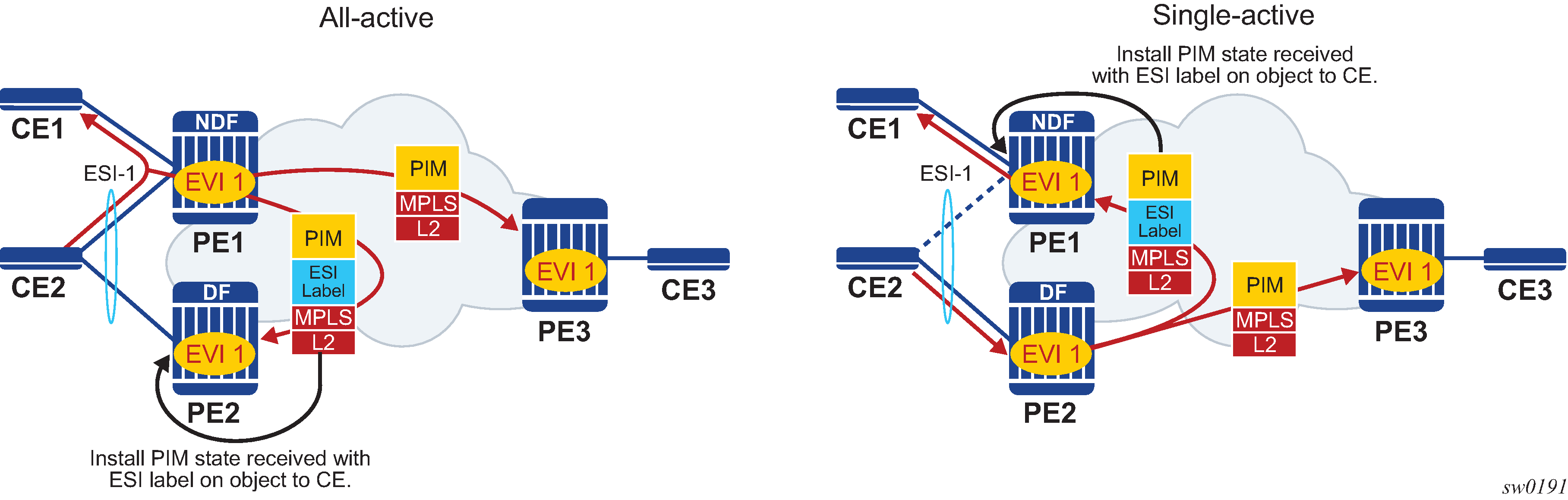
Data-driven synchronization is enabled by default when PIM snooping for IPv4 is enabled within an EVPN-MPLS service using all-active multihoming and single-active with an ESI label multihoming, or in a PBB-EVPN service using all-active multihoming. If PIM snooping for IPv4 MCS synchronization is enabled on an EVPN-MPLS or PBB-EVPN (I-VPLS) multihoming SAP or spoke SDP, then MCS synchronization takes preference over the data-driven synchronization and the MCS information is used. Mixing data-driven and MCS PIM synchronization within the same ES is not supported.
When using EVPN-MPLS, the ES should be configured as non-revertive to avoid an outage when a PE takes over the DF role. The Ethernet A-D per ESI route update is withdrawn when the ES is down, which prevents state synchronization to the PE with the ES down as it does not advertise an ESI label. The lack of state synchronization means that if the ES comes up and that PE becomes DF after the ES activation timer expires, it may not have any PIM snooping for IPv4 state until the next PIM messages are received, potentially resulting in an additional outage. Configuring the ES as non-revertive can avoid this potential outage. Configuring the ES to be non-revertive would also avoid an outage when PBB-EVPN is used, but there is no outage related to the lack of the ESI label as it is not used in PBB-EVPN.
The following steps can be used when enabling PIM snooping for IPv4 (using PIM snooping and PIM proxy modes) in EVPN-MPLS and PBB-EVPN services:
PIM snooping mode
-
Upgrade SR OS on all ES PEs to a version supporting data-driven PIM snooping for IPv4 synchronization with EVPN multihoming.
-
Enable PIM snooping for IPv4 on all ES PEs. Traffic loss occurs until all PEs have PIM snooping for IPv4 enabled and the first set of join/hello messages are processed by the ES PEs.
Note: There is no action required on the non-ES PEs.
-
PIM proxy mode
EVPN-MPLS
-
Upgrade SR OS on all ES PEs to a version supporting data-driven PIM snooping for IPv4 synchronization with EVPN multihoming.
-
Enable PIM snooping for IPv4 on all ES PEs. Traffic loss occurs until all PEs have PIM snooping for IPv4 enabled and the first set of join/hello messages are processed by the ES PEs.
Note: There is no action required on the non-ES PEs.
-
PBB-EVPN
-
Upgrade SR OS on all PEs (both ES and non-ES) to a version supporting data-driven PIM snooping for IPv4 synchronization with EVPN multihoming.
-
Enable PIM snooping for IPv4 on all non-ES PEs. Traffic loss occurs until all PEs have PIM snooping for IPv4 enabled and the first set of join/hello messages are processed by each non-ES PE.
-
Enable PIM snooping for IPv4 on all ES PEs. Traffic loss occurs until all PEs have PIM snooping for IPv4 enabled and the first set of join/hello messages are processed by the ES PEs.
-
If P2MP mLDP LSPs are also configured, the following steps can be used when enabling PIM snooping or IPv4 (using PIM snooping and PIM proxy modes) in EVPN-MPLS and PBB-EVPN services.
PIM snooping mode
-
Upgrade SR OS on all PEs (both ES and non-ES) to a version supporting data-driven PIM snooping for IPv4 synchronization with EVPN multihoming.
-
Then enable PIM snooping for IPv4 on all ES PEs. Traffic loss occurs until all PEs have PIM snooping enabled and the first set of join/hello messages are processed by the ES PEs.
Note: There is no action required on the non-ES PEs.
-
PIM proxy mode
-
Upgrade SR OS on all PEs (both ES and non-ES) to a version supporting data-driven PIM snooping for IPv4 synchronization with EVPN multihoming.
-
Enable PIM snooping for IPv4 on all non-ES PEs. Traffic loss occurs until all PEs have PIM snooping for IPv4 enabled and the first set of join/hello messages are processed by each non-ES PE.
-
Enable PIM snooping for IPv4 on all ES PEs. Traffic loss occurs until all PEs have PIM snooping enabled and the first set of join/hello messages are processed by the ES PEs.
-
In the above steps, when PIM snooping for IPv4 is enabled, the traffic loss can be reduced or eliminated by configuring a larger hold-time (up to 300 seconds), during which multicast traffic is flooded.
To aid with troubleshooting, the debug packet output displays the PIM packets used for the snooping state synchronization. An example of a join sent on ES esi-1 from one ES PE and the same join received on another ES PE follows:
6 2017/06/16 17:36:37.144 PDT MINOR: DEBUG #2001 Base PIM[vpls 1 ]
"PIM[vpls 1 ]: pimVplsFwdJPToEvpn
Forwarding to remote peer on bgp-evpn ethernet-segment esi-1"
7 2017/06/16 17:36:37.144 PDT MINOR: DEBUG #2001 Base PIM[vpls 1 ]
"PIM[vpls 1 ]: Join/Prune
[000 00:19:37.040] PIM-TX ifId 1071394 ifName EVPN-MPLS-ES:esi-1 10.0.0.10 -> 22
10.0.0.13 Length: 34
PIM Version: 2 Msg Type: Join/Prune Checksum: 0xd2de
Upstream Nbr IP : 10.0.0.1 Resvd: 0x0, Num Groups 1, HoldTime 210
        Group: 239.0.0.10/32 Num Joined Srcs: 1, Num Pruned Srcs: 0
        Joined Srcs:
                10.0.0.1/32 Flag SWR  <*,G>


4 2017/06/16 17:36:37.144 PDT MINOR: DEBUG #2001 Base PIM[vpls 1 ]
"PIM[vpls 1 ]: pimProcessPdu
Received from remote peer on bgp-evpn ethernet-segment esi-1, will be applied on
 lag-1:1
"
5 2017/06/16 17:36:37.144 PDT MINOR: DEBUG #2001 Base PIM[vpls 1 ]
"PIM[vpls 1 ]: Join/Prune
[000 00:19:30.740] PIM-RX ifId 1071394 ifName EVPN-MPLS-ES:esi-1 10.0.0.10 -> 22
10.0.0.13 Length: 34
PIM Version: 2 Msg Type: Join/Prune Checksum: 0xd2de
Upstream Nbr IP : 10.0.0.1 Resvd: 0x0, Num Groups 1, HoldTime 210
        Group: 239.0.0.10/32 Num Joined Srcs: 1, Num Pruned Srcs: 0
        Joined Srcs:
                10.0.0.1/32 Flag SWR  <*,G>
MPLS hash label
The router supports the Flow Aware Transport label, known as the hash label, (RFC 6391) on spoke SDPs bound to a VPLS EVPN service, as well as on EVPN unicast destinations (in Epipe and VPLS services) if enabled by the hash-label command. This label allows LSR nodes in a network to load-balance labeled packets in a much more granular fashion than allowed by simply hashing on the standard label stack.
The hash label is configured using the hash-label command in the spoke-sdp context.
Inter-AS Option B and Next-Hop-Self Route-Reflector for EVPN-MPLS
Inter-AS Option B and Next-Hop-Self Route-Reflector (VPN-NH-RR) functions are supported for the BGP-EVPN family in the same way both functions are supported for IP-VPN families.
A typical use case for EVPN Inter-AS Option B or EVPN VPN-NH-RR is Data Center Interconnect (DCI) networks, where cloud and service providers are looking for efficient ways to extend their Layer 2 and Layer 3 tenant services beyond the data center and provide a tighter DC-WAN integration. While the instantiation of EVPN services in the DGW to provide this DCI connectivity is a common model, some operators use Inter-AS Option B or VPN-NH-RR connectivity to allow the DGW to function as an ASBR or ABR respectively, and the services are only instantiated on the edge devices.
EVPN inter-AS Option B or VPN-NH-RR model shows a DCI example where the EVPN services in two DCs are interconnected without the need for instantiating services on the DC GWs.
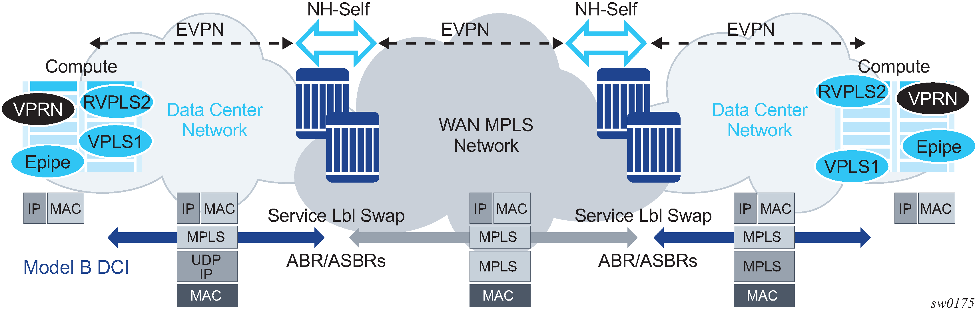
The ASBRs or ABRs connect the DC to the WAN at the control plane and data plane levels where the following considerations apply:
From a control plane perspective, the ASBRs or ABRs perform the following tasks:
-
accept EVPN-MPLS routes from a BGP peer
EVPN-VXLAN routes are not supported.
-
extract the MPLS label from the EVPN NLRI or attribute and program a label swap operation on the IOM
-
re-advertise the EVPN-MPLS route to the BGP peer in the other Autonomous Systems (ASs) or IGP domains
The re-advertised route has a Next-Hop-Self and a new label encoded for those routes that came with a label.
-
From a data plan perspective, the ASBRs and ABRs terminate the ingress transport tunnel, perform an EVPN label swap operation, and send the packets on to an interface (if E-BGP is used) or a new tunnel (if IBGP is used).
The ASBR or ABR resolves the EVPN routes based on the existing bgp next-hop-resolution command for family vpn, where vpn refers to EVPN, VPN-IPv4, and VPN-IPv6 families.
*A:ABR-1# configure router bgp next-hop-resolution labeled-routes transport-tunnel
family vpn resolution-filter
  - resolution-filter
 [no] bgp             - Use BGP tunnelling for next hop resolution
 [no] ldp             - Use LDP tunnelling for next hop resolution
 [no] rsvp            - Use RSVP tunnelling for next hop resolution
 [no] sr-isis         - Use sr-isis tunnelling for next hop resolution
 [no] sr-ospf         - Use sr-ospf for next hop resolution
 [no] sr-te           - Use sr-te for next hop resolution
 [no] udp             - Use udp for next hop resolution
For more information about the next-hop resolution of BGP-labeled routes, see the 7705 SAR Gen 2 Unicast Routing Protocols Guide
Inter-AS Option B for EVPN services on ABSRs and VPN-NH-RR on ABRs re-use the existing commands enable-inter-as-vpn and enable-rr-vpn-forwarding respectively. The two commands enable the ASBR or ABR function for both EVPN and IP-VPN routes. These two features can be used with the following EVPN services:
EVPN-MPLS Epipe services (EVPN-VPWS)
EVPN-MPLS VPLS services
EVPN-MPLS R-VPLS services
PBB-EVPN and PBB-EVPN E-Tree services
EVPN-MPLS E-Tree services
PE and ABR functions (EVPN services and enable-rr-vpn-forwarding), which are both supported on the same router
PE and ASBR functions (EVPN services and enable-inter-as-vpn), which are both supported on the same router
The following sub-sections clarify some aspects of EVPN when used in an Inter-AS Option B or VPN-NH-RR network.
Inter-AS Option B and VPN-NH-RR procedures on EVPN routes
When enable-rr-vpn-forwarding or enable-inter-as-vpn is configured, only EVPN-MPLS routes are processed for label swap and the next hop is changed. EVPN-VXLAN routes are re-advertised without a change in the next hop.
The following shows how the router processes and re-advertises the different EVPN route types. For more information about the route fields, see the BGP-EVPN control plane for MPLS tunnels Guide.
Auto-discovery (AD) routes (type 1)
For AD per EVI routes, the MPLS label is extracted from the route NLRI. The route is re-advertised with Next-Hop-Self (NHS) and a new label. No modifications are made for the remaining attributes.
For AD per ES routes, the MPLS label in the NLRI is zero. The route is re-advertised with NHS and the MPLS label remains zero. No modifications are made for the remaining attributes.
MAC/IP routes (type 2)
The MPLS label (Label-1) is extracted from the NLRI. The route is re-advertised with NHS and a new Label-1. No modifications are made for the remaining attributes.
Inclusive Multicast Ethernet Tag (IMET) routes (type 3)
Because there is no MPLS label present in the NLRI, the MPLS label is extracted from the PMSI Tunnel Attribute (PTA) if needed, and the route is then re-advertised with NHS, with the following considerations:
For IMET routes with tunnel-type Ingress Replication, the router extracts the IR label from the PTA. The router programs the label swap and re-advertises the route with a new label in the PTA.
For tunnel-type P2MP mLDP, the router re-advertises the route with NHS. No label is extracted; therefore, no swap operation occurs.
For tunnel-type Composite, the IR label is extracted from the PTA, the swap operation is programmed and the route re-advertised with NHS. A new label is encoded in the PTA’s IR label with no other changes in the remaining fields.
For tunnel-type AR, the routes are always considered VXLAN routes and are re-advertised with the next-hop unchanged.
Ethernet-Segment (ES) routes (type 4)
Because ES routes do not contain an MPLS label, the route is re-advertised with NHS and no modifications to the remaining attributes. Although an ASBR or ABR re-advertises ES routes, EVPN multihoming for ES PEs located in different ASs or IGMP domains is not supported.
IP-Prefix routes (type 5)
The MPLS label is extracted from the NLRI and the route is re-advertised with NHS and a new label. No modifications are made to the remaining attributes.
BUM traffic in inter-AS Option B and VPN-NH-RR networks
Inter-AS Option B and VPN-NH-RR support the use of non-segmented trees for forwarding BUM traffic in EVPN.
For ingress replication and non-segmented trees, the ASBR or ABR performs an EVPN BUM label swap without any aggregation or further replication. This concept is shown in VPN-NH-RR and ingress replication for BUM traffic.
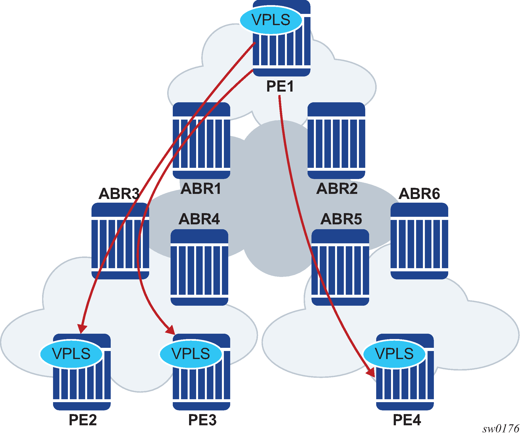
In VPN-NH-RR and ingress replication for BUM traffic, when PE2, PE3, and PE4 advertise their IMET routes, the ABRs re-advertise the routes with NHS and a different label. However, IMET routes are not aggregated; therefore, PE1 sets up three different EVPN multicast destinations and sends three copies of every BUM packet, even if they are sent to the same ABR. This example is also applicable to ASBRs and Inter-AS Option B.
P2MP mLDP may also be used with VPN-NH-RR, but not with Inter-AS Option B. The ABRs, however, do not aggregate or change the mLDP root IP addresses in the IMET routes. The root IP addresses must be leaked across IGP domains. For example, if PE2 advertises an IMET route with mLDP or composite tunnel type, PE1 is able to join the mLDP tree if the root IP is leaked into PE1’s IGP domain.
ECMP for EVPN-MPLS destinations
ECMP is supported for EVPN route next hops that are resolved to EVPN-MPLS destinations as follows:
ECMP for Layer 2 unicast traffic on Epipe and VPLS services for EVPN-MPLS destinations
This is enabled by the configure service epipe bgp-evpn mpls auto-bind-tunnel ecmp number and configure service vpls bgp-evpn mpls auto-bind-tunnel ecmp commands and allows the resolution of an EVPN-MPLS next hop to a group of ECMP tunnels of type RSVP-TE, SR-TE or BGP.
ECMP for Layer 3 unicast traffic on R-VPLS services with EVPN-MPLS destinations
This is enabled by the configure service vpls bgp-evpn mpls auto-bind-tunnel ecmp and configure service vpls allow-ip-int-bind evpn-mpls-ecmp commands.
The VPRN unicast traffic (IPv4 and IPv6) is sprayed among ‟m” paths, with ‟m” being the lowest value of (16,n), where ‟n” is the number of ECMP paths configured in the configure service vpls bgp-evpn mpls auto-bind-tunnel ecmp command.
CPM originated traffic is not sprayed and picks up the first tunnel in the set.
This feature is limited to FP3 and above systems.
ECMP for Layer 3 multicast traffic on R-VPLS services with EVPN-MPLS destinations
This is enabled by the configure service vpls allow-ip-int-bind ip-multicast-ecmp and configure service vpls bgp-evpn mpls auto-bind-tunnel ecmp commands. The VPRN multicast traffic (IPv4 and IPv6) are sprayed among up to ‟m” paths, with ‟m” being the lowest value of (16,n), and ‟n” is the number of ECMP paths configured in the configure service vpls bgp-evpn mpls auto-bind-tunnel ecmp command.
In all of these cases, the configure service epipe bgp-evpn mpls auto-bind-tunnel ecmp number and configure service vpls bgp-evpn mpls auto-bind-tunnel ecmp number commands determine the number of Traffic Engineering (TE) tunnels that an EVPN next hop can resolved to. TE tunnels refer to RSVP-TE or SR-TE types. For shortest path tunnels, such as, ldp, sr-isis, sr-ospf, udp, and so on, the number of tunnels in the ECMP group are determined by the configure router ecmp command.
Weighted ECMP for Layer 2 unicast traffic on Epipe and VPLS services for EVPN-MPLS destinations is supported. Packets are sprayed across the LSPs according to the outcome of the hash algorithm and the configured load balancing weight of each LSP when both:
-
the Epipe or VPLS service directly uses an ECMP set of RSVP or SR-TE LSPs with the configure router mpls lsp load-balancing-weight command configured
-
the configure service epipe bgp-evpn mpls auto-bind-tunnel weighted-ecmp or configure service vpls bgp-evpn mpls auto-bind-tunnel weighted-ecmp commands are configured
If the service uses a BGP tunnel which uses an ECMP set of RSVP or SR-TE LSPs with a load-balancing-weight configured, the router performs weighted ECMP regardless of the setting of weighted-ecmp under the auto-bind-tunnel context.
IPv6 tunnel resolution for EVPN MPLS services
EVPN MPLS services can be deployed in a pure IPv6 network infrastructure, where IPv6 addresses are used as next hops of the advertised EVPN routes, and EVPN routes received with IPv6 next hops are resolved to tunnels in the IPv6 tunnel table.
To change the default system-ipv4 address that is advertised as the next hop for a local EVPN MPLS service, configure the route-next-hop {system-ipv4 | system-ipv6 | ip-address} CLI command using the config service vpls bgp-evpn mpls route-next-hop {system-ipv4 | system-ipv6 | ip-address} or the config service epipe bgp-evpn mpls route-next-hop {system-ipv4 | system-ipv6 | ip-address} context.
The configured IP address is used as a next hop for the MAC/IP, IMET, and AD per-EVI routes advertised for the service. This configured next hop can be overridden by a policy using the next-hop-self command.
In the case of Inter-AS model B or next-hop-self route-reflector scenarios, at the ASBR/ABR the following guidelines apply.
A route received with an IPv4 next hop can be readvertised to a neighbor with an IPv6 next hop. The advertise-ipv6-next-hops evpn command must be configured on that neighbor.
A route received with an IPv6 next hop can be readvertised to a neighbor with an IPv4 next hop. The no advertise-ipv6-next-hops evpn command must be configured on that neighbor.
General EVPN topics
This section provides information about general topics related to EVPN.
ARP/ND snooping and proxy support
VPLS services support proxy-ARP (Address Resolution Protocol) and proxy-ND (Neighbor Discovery) functions that can be enabled or disabled independently per service. When enabled (proxy-ARP/proxy-ND no shutdown), the system populates the corresponding proxy-ARP/proxy-ND table with IP--MAC entries learned from the following sources:
EVPN-received IP-MAC entries
User-configured static IP-MAC entries
Snooped dynamic IP-MAC entries (learned from ARP/GARP/NA messages received on local SAPs/SDP bindings)
In addition, any ingress ARP or ND frame on a SAP or SDP binding is intercepted and processed. ARP requests and Neighbor Solicitations are answered by the system if the requested IP address is present in the proxy table.
Proxy-ARP example usage in an EVPN network shows an example of how proxy-ARP is used in an EVPN network. Proxy-ND would work in a similar way. The MAC address notation in the diagram is shortened for readability.
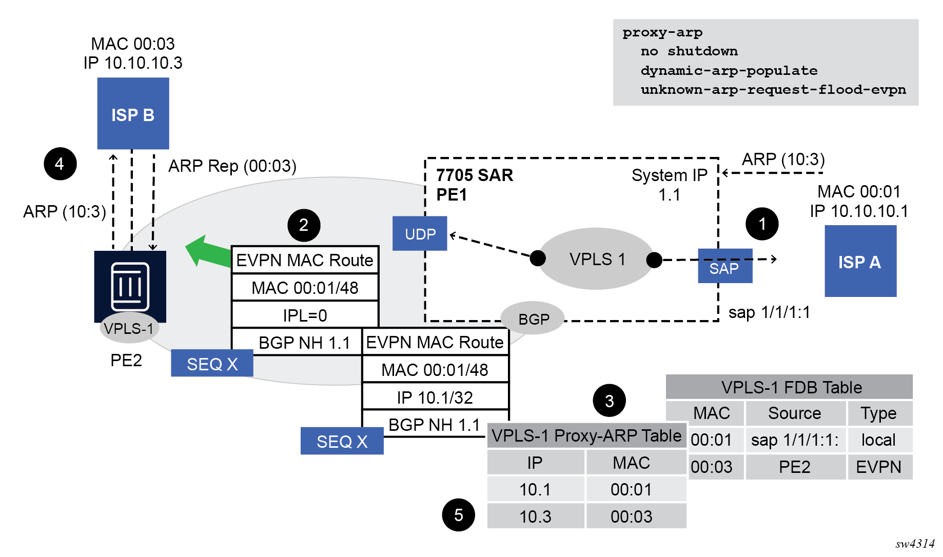
PE1 is configured as follows:
*A:PE1>config>service>vpls# info
----------------------------------------------
    vxlan instance 1 vni 600 create
        exit
        bgp
            route-distinguisher 192.0.2.71:600
            route-target export target:64500:600 import target:64500:600
    exit
    bgp-evpn
        vxlan bgp 1 vxlan-instance 1
            no shutdown
        exit
    exit
    proxy-arp
        age-time 600
        send-refresh 200
        dup-detect window 3 num-moves 3 hold-down max anti-spoof-
mac 00:ca:ca:ca:ca:ca
        dynamic-arp-populate
          no shutdown
            exit
            sap 1/1/1:600 create
            exit
    no shutdown
----------------------------------------------
Proxy-ARP example usage in an EVPN network shows the following steps, assuming proxy-ARP is no shutdown on PE1 and PE2, and the tables are empty:
ISP-A sends ARP-request for (10.10.)10.3.
PE1 learns the MAC 00:01 in the FDB as usual and advertises it in EVPN without any IP. Optionally, the MAC can be configured as a CStatic mac, in which case it is advertised as protected. If the MAC is learned on a SAP or SDP binding where auto-learn-mac-protect is enabled, the MAC is also advertised as protected.
The ARP-request is sent to the CPM where:
An ARP entry (IP 10.1'MAC 00:01) is populated into the proxy-ARP table.
EVPN advertises MAC 00:01 and IP 10.1 in EVPN with the same SEQ number and Protected bit as the previous route-type 2 for MAC 00:01.
A GARP is also issued to other SAPs/SDP bindings (assuming they are not in the same split horizon group as the source). If garp-flood-evpn is enabled, the GARP message is also sent to the EVPN network.
The original ARP-request can still be flooded to the EVPN or not based on the unknown-arp-request-flood-evpn command.
Assuming PE1 was configured with unknown-arp-request-flood-evpn, the ARP-request is flooded to PE2 and delivered to ISP-B. ISP-B replies with its MAC in the ARP-reply. The ARP-reply is finally delivered to ISP-A.
PE2 learns MAC 00:01 in the FDB and the entry 10.1'00:01 in the proxy-ARP table, based on the EVPN advertisements.
When ISP-B replies with its MAC in the ARP-reply:
MAC 00:03 is learned in FDB at PE2 and advertised in EVPN.
MAC 00:03 and IP 10.3 are learned in the proxy-ARP table and advertised in EVPN with the same SEQ number as the previous MAC route.
ARP-reply is unicasted to MAC 00:01.
EVPN advertisements are used to populate PE1's FDB (MAC 00:03) and proxy-ARP (IP 10.3—>MAC 00:03) tables as mentioned in 5.
From this point onward, the PEs reply to any ARP-request for 00:01 or 00:03, without the need for flooding the message in the EVPN network. By replying to known ARP-requests / Neighbor Solicitations, the PEs help to significantly reduce the flooding in the network.
Use the following commands to customize proxy-ARP/proxy-ND behavior:
dynamic-arp-populate and dynamic-nd-populate
Enables the addition of dynamic entries to the proxy-ARP or proxy-ND table (disabled by default). When executed, the system populates proxy-ARP/proxy-ND entries from snooped GARP/ARP/NA messages on SAPs/SDP bindings in addition to the entries coming from EVPN (if EVPN is enabled). These entries are shown as dynamic.
static <IPv4-address> <mac-address> and static <IPv4-address> <mac-address> and static <ipv6-address> <mac-address> {host | router}
Configures static entries to be added to the table.
Note: A static IP-MAC entry requires the addition of the MAC address to the FDB as either learned or CStatic (conditional static mac) to become active (Status —> active).age-time <60 to 86400> (seconds)
Specifies the aging timer per proxy-ARP/proxy-ND entry. When the aging expires, the entry is flushed. The age is reset when a new ARP/GARP/NA for the same IP MAC is received.
send-refresh <120 to 86400> (seconds)
If enabled, the system sends ARP-request/Neighbor Solicitation messages at the configured time, so that the owner of the IP can reply and therefore refresh its IP MAC (proxy-ARP entry) and MAC (FDB entry).
-
table-size [1 to 16384]
Enables the user to limit the number of entries learned on a specified service. By default, the table-size limit is 250.
Use the following commands to configure whether unknown ARP-requests, NS, or the unsolicited GARPs and NA messages are flooded in an EVPN network:
-
MD-CLI
configure service vpls proxy-arp evpn flood unknown-arp-req configure service vpls proxy-arp evpn flood gratuitous-arp configure service vpls proxy-nd evpn flood unknown-neighbor-solicitation configure service vpls proxy-nd evpn flood unknown-neighbor-advertise-host configure service vpls proxy-nd evpn flood unknown-neighbor-advertise-router -
classic CLI
configure service vpls proxy-arp unknown-arp-request-flood-evpn
configure service vpls proxy-arp garp-flood-evpn
configure service vpls proxy-nd unknown-ns-flood-evpn
configure service vpls proxy-nd host-unsolicited-na-flood-evpn
configure service vpls proxy-nd router-unsolicited-na-flood-evpn
The preceding commands control whether ARP/ND messages are flooded to EVPN destinations only. That is, when flooding (for a specific message type) is configured to be blocked when sending to EVPN, it is still flooded to other local SAPs or SDP-binds. Use the following commands if the desired behavior is to block flooding in the service, even to local SAPs and SDP-binds:
- MD-CLI
configure service vpls proxy-arp flood received-unknown-arp-req configure service vpls proxy-arp flood received-gratuitous-arp configure service vpls proxy-nd flood received-unknown-neighbor-solicitation configure service vpls proxy-nd flood received-unknown-neighbor-advertise-host configure service vpls proxy-nd flood received-unknown-neighbor-advertise-router - classic
CLI
configure service vpls proxy-arp received-unknown-arp-request-flood
configure service vpls proxy-arp received-garp-flood
configure service vpls proxy-nd received-unknown-ns-flood
configure service vpls proxy-nd received-host-unsolicited-na-flood
configure service vpls proxy-nd received-router-unsolicited-na-flood
-
dup-detect [anti-spoof-mac <mac-address>] window <minutes> num-moves <count> hold-down <minutes | max>
Enables a mechanism that detects duplicate IPs and ARP/ND spoofing attacks. The working of the dup-detect command can be summarized as follows:
Attempts (relevant to dynamic and EVPN entry types) to add the same IP (different MAC) are monitored for <window> minutes and when <count> is reached within that window, the proxy-ARP/proxy-ND entry for the IP is suspected and marked as duplicate. An alarm is also triggered.
The condition is cleared when hold-down time expires (max does not expire) or a clear command is issued.
If the anti-spoof-mac is configured, the proxy-ARP/proxy-ND offending entry's MAC is replaced by this <mac-address> and advertised in an unsolicited GARP/NA for local SAP or SDP bindings and in EVPN to remote PEs.
This mechanism assumes that the same anti-spoof-mac is configured in all the PEs for the same service and that traffic with destination anti-spoof-mac received on SAPs/SDP bindings are dropped. An ingress MAC filter has to be configured to drop traffic to the anti-spoof-mac.
Proxy-arp entry combinations shows the combinations that produce a Status = Active proxy-arp entry in the table. The system replies to proxy-ARP requests for active entries. Any other combination results in a Status = inActv entry. If the service is not active, the proxy-arp entries are not active either, regardless of the FDB entries
| Proxy-arp entry type | FDB entry type (for the same MAC) |
|---|---|
Dynamic |
learned |
Static |
learned |
Dynamic |
CStatic/Static |
Static |
CStatic/Static |
EVPN |
EVPN, learned/CStatic/Static with matching ESI |
Duplicate |
— |
When proxy-ARP/proxy-ND is enabled on services with all-active multihomed Ethernet Segments, a proxy-arp entry type evpn may be associated with learned/CStatic/Static FDB entries (because for example, the CE can send traffic for the same MAC to all the multihomed PEs in the ES). If this is the case, the entry is active if the ESI of the EVPN route and the FDB entry match, or inactive otherwise, as per Proxy-arp entry combinations.
Proxy-ARP/ND periodic refresh, unsolicited refresh and confirm-messages
When proxy-ARP/proxy-ND is enabled, the system starts populating the proxy table and responding to ARP-requests/NS messages. To keep the active IP→MAC entries alive and ensure that all the host/routers in the service update their ARP/ND caches, the system may generate the following three types of ARP/ND messages for a specified IP→MAC entry:
periodic refresh messages (ARP-requests or NS for a specified IP)
These messages are activated by the send-refresh command and their objective is to keep the existing FDB and Proxy-ARP/ND entries alive, to minimize EVPN withdrawals and re-advertisements.
unsolicited refresh messages (unsolicited GARP or NA messages)
These messages are sent by the system when a new entry is learned or updated. Their objective is to update the attached host/router caches.
confirm messages (unicast ARP-requests or unicast NS messages)
These messages are sent by the system when a new MAC is learned for an existing IP. The objective of the confirm messages is to verify that a specified IP has really moved to a different part of the network and is associated with the new MAC. If the IP has not moved, it forces the owners of the duplicate IP to reply and cause dup-detect to kick in.
Advertisement of Proxy-ARP/ND flags in EVPN
- The Router Flag (R) - used in IPv6 Neighbor Advertisement messages to indicate if the proxy-ND entry belongs to an IPv6 router or an IPv6 host.
- The Override Flag (O) - used in IPv6 Neighbor Advertisement messages to indicate whether the resolved entry should override a potential ND entry that the solicitor may already have for the same IPv6 address.
- The Immutable Flag (I) - used to indicate that the proxy-ARP/ND entry cannot change its binding to a different MAC addresses. This Flag is always set for static proxy-ARP/ND entries or configured dynamic IP addresses that are associated with a mac-list.
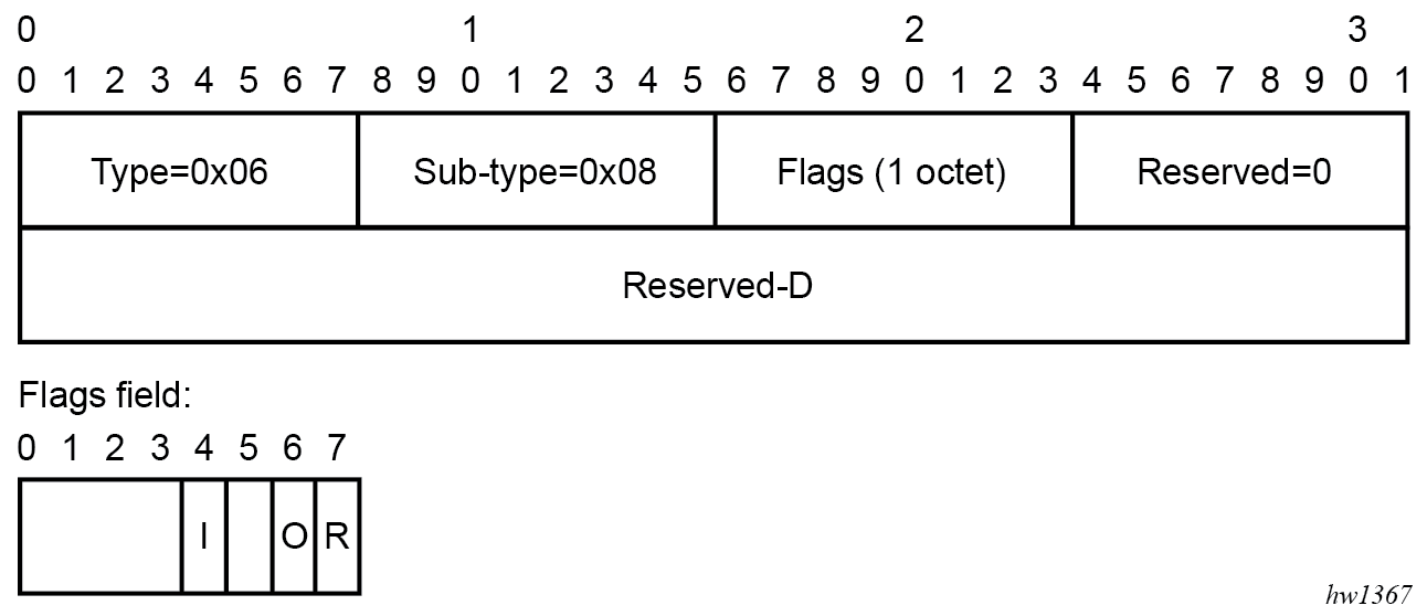
By default, the router does not advertise the ARP/ND extended community. Use the following command to configure the router to advertise all the proxy ARP/ND MAC/IP Advertisement routes with the extended community:
configure service vpls bgp-evpn arp-nd-extended-communityProxy-ARP/ND and flag processing
Proxy-ND and the Router Flag
RFC 4861 describes the use of the (R) or Router flag in NA messages as follows:
-
A node capable of routing IPv6 packets must reply to NS messages with NA messages where the R flag is set (R=1).
-
Hosts must reply with NA messages where R=0.
The R flag in NA messages impacts how the hosts select their default gateways when sending packets off-link. The proxy-ND function on the router does one of the following, depending on whether it can provide the appropriate R flag information:
-
provides the appropriate R flag information in the proxy-ND NA replies, if possible
-
floods the received NA messages, if it cannot provide the appropriate R flag when replying
The use of the R flag (only present in NA messages and not in NS messages) makes the procedure for learning proxy-ND entries and replying to NS messages different from the procedures for proxy-ARP in IPv4. The NA messages snooping determines the router or host flag to add to each entry, and that determines the flag to use when responding to an NS message.
The procedure to add the R flag to a specified entry is as follows:
-
Dynamic entries are learned based on received NA messages. The R flag is also learned and added to the proxy-ND entry so that the appropriate R flag is used in response to NS requests for a specified IP.
-
Static entries are configured as host or router using the following command.
- MD-CLI
configure service vpls proxy-nd static-neighbor ip-address type - classic
CLI
configure service vpls proxy-nd static
- MD-CLI
-
EVPN entries are learned from BGP and the following command determines the R flag added to them;
- MD-CLI
configure service vpls proxy-nd evpn advertise-neighbor-type - classic
CLI
configure service vpls proxy-nd evpn-nd-advertise
- MD-CLI
configure service vpls bgp-evpn routes mac-ip arp-nd-extended-community - classic
CLI
configure service vpls bgp-evpn arp-nd-extended-community-advertisement
- MD-CLI
-
In addition, the EVPN ND advertisement indicates what static and dynamic IP → MAC entries the system advertises in EVPN.
-
If you specify the router option for EVPN ND advertisement, the system should flood the received unsolicited NA messages for hosts. This is controlled by the following command:
- MD-CLI
configure service vpls proxy-nd evpn flood unknown-neighbor-advertise-host - classic
CLI
configure service vpls proxy-nd host-unsolicited-na-flood-evpn
- MD-CLI
-
The opposite is also true so that the host option for EVPN ND advertisement is configured with the following command:
- MD-CLI
configure service vpls proxy-nd evpn flood unknown-neighbor-advertise-router - classic
CLI
configure service vpls proxy-nd router-unsolicited-na-flood-evpn
- MD-CLI
- The router-host option for EVPN ND advertisement allows the router to advertise both types of entries in EVPN at the same time. That is, static and dynamic entries with the router or host flag are advertised in EVPN with the corresponding flag in the ARP/ND extended community. This option can be enabled only if the ARP/ND extended community is configured.
-
EVPN proxy-ND MAC/IP Advertisement routes received without the EVPN ARP/ND extended communities create an entry with type Router (which is the default value). Entries created as duplicate are advertised in EVPN with an R flag value that depends on the configuration of the EVPN ND advertisement command. If the host option is configured for the EVPN ND advertisement, the duplicate entry is treated as a host. If the router or router-host option is configured for the EVPN ND advertisement, the duplicate entry behaves as a router.
Proxy-ARP/ND and the Immutable Flag
The I bit or Immutable flag in the ARP/ND extended community is advertised and used as follows:
- Any static proxy-ARP/ND entry is advertised with I=1 if you enable ARP/ND extended community advertisement.
- Any configured dynamic IP address (associated with a mac-list) proxy-ARP/ND entry is advertised with I=1 if you enable ARP/ND extended community
- Duplicate entries are advertised with I=1 as well (in addition to O=1 and R=0 or 1 based on the configuration).
- The setting of the I bit is independent of the static bit associated with the FDB entry, and it is only used with proxy-ARP/ND advertisements.
The I bit in the ARP/ND extended community is processed on reception as follows:
- A PE receiving an EVPN MAC/IP Advertisement route containing an IP-MAC and the I flag set, installs the IP-MAC entry in the ARP/ND or proxy-ARP/ND table as an immutable binding.
- This immutable binding entry overrides an existing non-immutable binding for the same
IP-MAC. In general, the ARP/ND extended community command changes the selection
of ARP/ND entries when multiple routes with the same IP address exist. This
preferred order of ARP/ND entries selection is as follows:
- Local immutable ARP/ND entries (static and dynamic)
- EVPN immutable ARP/ND entries
- Remaining ARP/ND entries
- The absence of the EVPN ARP/ND Extended Community in a MAC/IP Advertisement route indicates that the IP→MAC entry is not an immutable binding.
- Receiving multiple EVPN MAC/IP Advertisement routes with the I flag set to 1 for the same IP but a different MAC address is considered a misconfiguration or a transient error condition. If this happens in the network, a PE receiving multiple routes (with the I flag set to 1 for the same IP and a different MAC address) selects one of them based on the previously described selection rules.
Proxy-ND and the Override Flag
- The O flag is learned for dynamic entries (being 0 or 1) and added to the proxy-ND table. If the ARP/ND extended community is configured, the O flag associated with the entry is advertised along with the EVPN MAC/IP Advertisement route. Static and duplicate entries are always advertised with O=1.
- Upon receiving an EVPN MAC/IP Advertisement route, the received O flag is stored in the entry created in the proxy-ND table, and used when replying to local NS messages for the IP address.
Proxy-ARP/ND mac-List for dynamic entries
SR OS supports the association of configured MAC lists with a configured dynamic proxy-ARP or proxy-ND IP address. The actual proxy-ARP or proxy-ND entry is not created until an ARP or Neighbor Advertisement message is received for the IP and one of the MACs in the associated MAC-list. This is in accordance with IETF RFC 9161, which states that a proxy-ARP or proxy-ND IP entry can be associated with one MAC among a list of allowed MACs.
The following example shows the use of MAC lists for dynamic entries.
A:PE-2>config>service#
  proxy-arp-nd
    mac-list ISP-1 create
      mac 00:de:ad:be:ef:01
      mac 00:de:ad:be:ef:02
      mac 00:de:ad:be:ef:03

A:PE-2>config>service>vpls>proxy-arp#
  dynamic 1.1.1.1 create
    mac-list ISP-1
    resolve 30

A:PE-2>config>service>vpls>proxy-nd#
  dynamic 2001:db8:1000::1 create
    mac-list ISP-1
    resolve 30
where:
-
A dynamic IP (dynamic ip create) is configured and associated with a MAC list (mac-list name).
-
The MAC list is created in the config>service context and can be reused by multiple configured dynamic IPs as follows:
-
in different services
-
in the same service, for proxy-ARP and proxy-ND entries
-
-
If the MAC list is empty, the proxy-ARP or proxy-ND entry is not created for the configured IP.
-
The same MAC list can be applied to multiple configured dynamic entries even within the same service.
-
The new proxy-ARP and proxy-ND entries behave as dynamic entries and are displayed as type dyn in the show commands.
The following output example displays the entry corresponding to the configured dynamic IP.
show service id 1 proxy-arp detail-------------------------------------------------------------------------------
Proxy Arp
-------------------------------------------------------------------------------
Admin State : enabled
Dyn Populate : enabled
Age Time : 900 secs Send Refresh : 300 secs
Table Size : 250 Total : 1
Static Count : 0 EVPN Count : 0
Dynamic Count : 1 Duplicate Count : 0
Dup Detect
-------------------------------------------------------------------------------
Detect Window : 3 mins Num Moves : 5
Hold down : 9 mins
Anti Spoof MAC : None
EVPN
-------------------------------------------------------------------------------
Garp Flood : enabled Req Flood : enabled
Static Black Hole : disabled
-------------------------------------------------------------------------------
===============================================================================
VPLS Proxy Arp Entries
===============================================================================
IP Address Mac Address Type Status Last Update
-------------------------------------------------------------------------------
1.1.1.1 00:de:ad:be:ef:01 dyn active 02/23/2016 09:05:49
-------------------------------------------------------------------------------
Number of entries : 1
===============================================================================show service proxy-arp-nd mac-list "ISP-1" associations===============================================================================
MAC List Associations
===============================================================================
Service Id IP Addr
-------------------------------------------------------------------------------
1 1.1.1.1
1 2001:db8:1000::1
-------------------------------------------------------------------------------
Number of Entries: 2
===============================================================================
Although no new proxy-ARP or proxy-ND entries are created when a dynamic IP is configured, the router triggers the following resolve procedure:
-
The router sends a resolve message with a configurable frequency of 1 to 60 minutes; the default value is five minutes.
Note: The resolve message is an ARP-request or NS message flooded to all the non-EVPN endpoints in the service. -
The router sends resolve messages at the configured frequency until a dynamic entry for the IP is created.
Note: The dynamic entry is created only if an ARP, GARP, or NA message is received for the configured IP, and the associated MAC belongs to the configured MAC list of the IP. If the MAC list is empty, the proxy-ARP or proxy-ND entry is not created for the configured IP.
After a dynamic entry (with a MAC address included in the list) is successfully created, its behavior (for send-refresh, age-time, and other activities) is the same as a configured dynamic entry with the following exceptions.
-
Regular dynamic entries may override configured dynamic entries, but static or EVPN entries cannot override configured dynamic entries.
-
If the corresponding MAC is flushed from the FDB after the entry is successfully created, the entry becomes inactive in the proxy-ARP or proxy-ND table and the resolve process is restarted.
-
If the MAC list is changed, all the IPs that point to the list delete the proxy entries and the resolve process is restarted.
-
If there is an existing configured dynamic entry and the router receives a GARP, ARP, or NA for the IP with a MAC that is not contained in the MAC list, the message is discarded and the proxy-ARP or proxy-ND entry is deleted. The resolve process is restarted.
-
If there is an existing configured dynamic entry and the router receives a GARP, ARP, or NA for the IP with a MAC contained in the MAC list, the existing entry is overridden by the IP and new MAC, assuming the confirm procedure passes.
-
The dup-detect and confirm procedures work for the configured dynamic entries when the MAC changes are between MACs in the MAC list. Changes to an off-list MAC cause the entry to be deleted and the resolve process is restarted.
- The CPM drops received dynamic ARP/ND messages without learning them, if they match a dynamic (immutable) entry.
- If there is a local configured dynamic address (irrespective of whether there is an entry for it or not), a received EVPN immutable entry for the same IP address is not installed. Therefore the IP duplication mechanisms do not apply to immutable entries.
Configured dynamic entries also allow other non-configured dynamic entries to be learned in the proxy-ARP or proxy-ND table. If a more restrictive configuration is needed, add the following configuration command:
-
The following command prevents the router from learning dynamic proxy-ARP or proxy-ND entries.
However, if the following command is used, the subsequent rules must be followed to create the proxy-ARP or proxy-ND entry:configure service vpls proxy-arp restrict-non-configured-ip-address configure service vpls proxy-nd restrict-non-configured-ip-address-
MD-CLI
configure service vpls proxy-arp dynamic-arp ip-address configure service vpls proxy-nd dynamic-arp ip-address -
classic CLI
configure service vpls proxy-arp dynamic create
configure service vpls proxy-nd dynamic create
Adhere to the following rules when creating the proxy-ARP or proxy-ND entry:
-
The MAC address of the entry must be associated with a MAC address contained in the MAC list (if configured).
-
The following command checks that the reply for a configured dynamic IP address is coming on that SAP. Otherwise, the entry is not created:
- MD-CLI
configure service vpls proxy-arp dynamic-arp ip-address sap configure service vpls proxy-nd dynamic-neighbor ip-address sap - classic
CLI
configure service vpls proxy-arp dynamic sap
configure service vpls proxy-nd dynamic sap
- MD-CLI
-
-
-
In addition, the following optional command is supported so that the router can reply with a configured sponge MAC to requests for an unauthorized IP address. Only the configured dynamic-ARP or dynamic-neighbor IP addresses that pass the MAC list or the SAP ID check are considered authorized IP addresses.
configure service vpls proxy-arp restrict-non-configured-ip-address sponge-mac
configure service vpls proxy-nd restrict-non-configured-ip-address sponge-mac
BGP-EVPN MAC mobility
EVPN defines a mechanism to allow the smooth mobility of MAC addresses from an NVE to another NVE. The 7705 SAR Gen 2 supports this procedure as well as the MAC-mobility extended community in MAC advertisement routes as follows:
The router honors and generates the SEQ number in the MAC mobility extended community for MAC moves.
When a MAC is EVPN-learned and it is attempted to be learned locally, a BGP update is sent with SEQ number changed to "previous SEQ"+1 (exception: mac-duplication detect num-moves value is reached).
A SEQ number = zero or no MAC mobility ext-community are interpreted as sequence zero.
In case of mobility, the following MAC selection procedure is performed.
If a PE has two or more active remote EVPN routes for the same MAC (VNI can be the same or different), the highest SEQ number is selected. The tie-breaker is the lowest IP (BGP NH IP).
If a PE has two or more active EVPN routes and it is the originator of one of them, the highest SEQ number is selected. The tie-breaker is the lowest IP (BGP NH IP of the remote route is compared to the local system address).
BGP-EVPN MAC duplication
EVPN defines a mechanism to protect the EVPN service from control plane churn as a result of loops or accidental duplicated MAC addresses. The 7705 SAR Gen 2 supports an enhanced version of this procedure as described in this section.
In a scenario where two or more hosts are misconfigured using the same (duplicate) MAC address, the duplicate MAC address is learned by the PEs in the VPLS. As a result, the traffic originating from the hosts triggers continuous MAC moves among the PEs attached to the hosts. It is important to recognize such a situation and avoid incrementing the sequence number (in the MAC Mobility attribute) to infinity.
To remedy such situation, a router that detects a MAC mobility event by way of local learning starts a window <in-minutes> timer (default value of window = 3) and if it detects num-moves <num> before the timer expires (default value of num-moves = 5), it concludes that a duplicate MAC situation has occurred. The window and number of moves are configured using the following commands.
configure service vpls bgp-evpn mac-duplication detect window
configure service vpls bgp-evpn mac-duplication detect num-moves
The router then alerts the operator with a trap message when a duplicate MAC situation occurs.
10 2014/01/14 01:00:22.91 UTC MINOR: SVCMGR #2331 Base
"VPLS Service 1 has MAC(s) detected as duplicates by EVPN mac-
duplication detection."
Use the following command in the BGP EVPN Table section to display the offending MAC address.
show service id svc-id bgp-evpnDisplaying duplicated MAC addresses
===============================================================================
BGP EVPN Table
===============================================================================
EVI : 1000
Creation Origin : manual

Adv L2 Attributes : Disabled
Ignore Mtu Mismatch: Disabled

MAC/IP Routes
MAC Advertisement : Enabled                Unknown MAC Route : Disabled
CFM MAC Advertise : Disabled
ARP/ND Ext Comm Adv: Disabled

Multicast Routes
Sel Mcast Advert : Disabled
Ing Rep Inc McastAd: Enabled

IP Prefix Routes
IP Route Advert : Disabled

MAC Duplication Detection
Num. Moves : 5                             Window : 3
Retry : 9                                  Number of Dup MACs : 1
Black Hole : Enabled
Local Learned Trusted MAC
MAC time : 1                               MAC move factor : 3


-------------------------------------------------------------------------------
Detected Duplicate MAC Addresses           Time Detected
-------------------------------------------------------------------------------
00:de:fe:ca:da:04                          05/18/2023 09:55:22
-------------------------------------------------------------------------------
===============================================================================


-------------------------------------------------------------------------------
Local Learned Trusted MAC
-------------------------------------------------------------------------------
MAC Address Time Detected
-------------------------------------------------------------------------------
-------------------------------------------------------------------------------
After a duplicate MAC is detected, the router stops sending and processing any BGP MAC advertisement routes for that MAC address until one of the following occurs.
-
The MAC is flushed because of a local event (SAP or SDP-binding associated with the MAC fails) or the reception of a remote update with better SEQ number (as a result of MAC flush at the remote router).
-
The retry in-minutes timer expires, which flushes the MAC and restart the process.
The values of num-moves and window are configurable to allow for the required flexibility in different environments. In scenarios where BGP configure router bgp rapid-update evpn is configured, the operator may want to configure a shorter window timer than in scenarios where BGP updates are sent every (default) min-route-advertisement interval.
MAC duplication is always enabled in EVPN VPLS services. The preceding example shows the output for BGP-EVPN MAC duplication detection configuration per VPLS service under the following context.
configure service vpls bgp-evpn mac-duplicationThe following example shows a MAC duplication detection configuration.
MD-CLI
[ex:/configure service vpls "bd-1000-mac-dup-mpls" bgp-evpn mac-duplication]
A:admin@node-2# info detail
retry 9
detect {
    num-moves 5
    window 3
}
classic CLI
A:node-2>config>service>vpls>bgp-evpn>mac-duplication# info detail
----------------------------------------------
detect num-moves 5 window 3 trusted-mac-move-factor 3
retry 9
Conditional static MAC and protection
RFC 7432, MAC mobility Extended Community section defines the use of the sticky bit to signal static MAC addresses. These addresses must be protected to prevent attempts to dynamically learn them in a different place in the EVPN-MPLS/VXLAN VPLS service.
Any conditional static MAC address that is defined in an EVPN-MPLS/VXLAN VPLS service is advertised by BGP-EVPN as a static address (that is, with the sticky bit set). Local static MACs or remote MACs with the sticky bit set are considered ‟protected”. A packet entering a SAP/SDP-binding is discarded if its source MAC address matches a ‟protected” MAC.
A:node2config>service>vpls# info
----------------------------------------------
            description "vxlan-service"
...
            sap 1/1/1:1000 create
            exit
            static-mac
                mac 00:ca:ca:ca:ca:00 create sap 1/1/1:1000 monitor fwd-status
            exit
            no shutdown

A:node-2# show router bgp routes evpn mac hunt mac-address 00:ca:ca:ca:ca:00
...
===============================================================================
BGP EVPN Mac Routes
===============================================================================
Network        : 0.0.0.0/0
Nexthop        : 192.0.2.63
From           : 192.0.2.63
Res. Nexthop   : 192.168.19.1
Local Pref.    : 100                    Interface Name : NotAvailable
Aggregator AS  : None                   Aggregator     : None
Atomic Aggr.   : Not Atomic             MED            : 0
AIGP Metric    : None
Connector      : None
Community      : target:65000:1000     mac-mobility:Seq: 0/Static
Cluster        : No Cluster Members
Originator Id  : None                   Peer Router Id : 192.0.2.63
Flags          : Used  Valid  Best  IGP
Route Source   : Internal
AS-Path        : No As-Path
EVPN type      : MAC
ESI            : 0:0:0:0:0:0:0:0:0:0    Tag            : 1063
IP Address     : ::                     RD             : 65063:1000
Mac Address    : 00:ca:ca:ca:ca:00      Mac Mobility   : Seq:0
Neighbor-AS    : N/A
Source Class   : 0                      Dest Class     : 0
-------------------------------------------------------------------------------
Routes : 1
===============================================================================
Local static MACs or remote MACs with sticky bit are considered as "protected". A packet entering a SAP / SDP binding is discarded if its source MAC address matches one of these 'protected' MACs.
Auto-learn MAC protect and restricting protected source MACs
Auto-learn MAC protect, together with the ability to restrict where the protected source MACs are allowed to enter the service, can be enabled within an EVPN-MPLS and EVPN-VXLAN VPLS and routed VPLS services, but not in PBB-EVPN services. The protection, using the auto-learn-mac-protect command (described in Auto-learn MAC protect), and the restrictions, using the restrict-protected-src [discard-frame] command, operate in the same way as in a non-EVPN VPLS service.
When auto-learn-mac-protect is enabled on an object, source MAC addresses learned on that object are marked as protected within the FDB.
When restrict-protected-src is enabled on an object and a protected source MAC is received on that object, the object is automatically shutdown (requiring the user to shutdown then no shutdown the object to make it operational again).
When restrict-protected-src discard-frame is enabled on an object and a frame with a protected source MAC is received on that object, that frame is discarded.
In addition, the following behavioral differences are specific to EVPN services:
An implicit restrict-protected-src discard-frame command is enabled by default on SAPs, mesh-SDPs and spoke SDPs. As this is the default, it is not possible to configure this command in an EVPN service. This default state can be seen in the show output for these objects, for example on a SAP:
*A:PE# show service id 1 sap 1/1/9:1 detail
===============================================================================
Service Access Points(SAP)
===============================================================================
Service Id         : 1
SAP                : 1/1/9:1                  Encap             : q-tag
...
RestMacProtSrc Act : none (oper: Discard-frame)
A restrict-protected-src discard-frame can be optionally enabled on EVPN-MPLS/VXLAN destinations within EVPN services. When enabled, frames that have a protected source MAC address are discarded if received on any EVPN-MPLS/VXLAN destination in this service, unless the MAC address is learned and protected on an EVPN-MPLS/VXLAN destination in this service. This is enabled as follows:
        configure
           service
              vpls <service id>
                   bgp-evpn
                       mpls bgp <instance>
                           [no] restrict-protected-src discard-frame
                   vxlan instance <instance> vni <vni-id>
                       [no] restrict-protected-src discard-frame
Auto-learned protected MACs are advertised to remote PEs in an EVPN MAC/IP advertisement route with the sticky bit set.
The source MAC protection action relating to the restrict-protected-src [discard-frame] commands also applies to MAC addresses learned by receiving an EVPN MAC/IP advertisement route with the sticky bit set from remote PEs. This causes remotely configured conditional static MACs and auto-learned protected MACs to be protected locally.
In all-active multihoming scenarios, if auto-learn-mac-protect is configured on all-active SAPs and restrict-protected-src discard-frame is enabled on EVPN-MPLS/VXLAN destinations, traffic from the CE that enters one multihoming PE and needs to be switched through the other multihoming PE is discarded on the second multihoming PE. Each multihoming PE protects the CE's MAC on its local all-active SAP, which results in any frames with the CE's MAC address as the source MAC being discarded as they are received on the EVPN-MPLS/VXLAN destination from the other multihoming PE.
Conditional static MACs, EVPN static MACs and locally protected MACs are marked as protected within the FDB, as shown in the example output.
*A:PE# show service fdb-mac
===============================================================================
Service Forwarding Database
===============================================================================
ServId    MAC               Source-Identifier        Type     Last Change
                                                     Age
-------------------------------------------------------------------------------
1         00:00:00:00:00:01 sap:1/1/9:1              LP/30    01/05/16 11:58:22
1         00:00:00:00:00:02 vxlan-1:                 EvpnS:P  01/05/16 11:58:23
                            10.1.1.2:1
1         00:00:00:00:01:01 sap:1/1/9:1              CStatic: 01/04/16 20:05:02
                                                     P
1         00:00:00:00:01:02 vxlan-1:                 EvpnS:P  01/04/16 20:18:02
                            10.1.1.2:1
-------------------------------------------------------------------------------
No. of Entries: 4
-------------------------------------------------------------------------------
Legend:  L=Learned O=Oam P=Protected-MAC C=Conditional S=Static
===============================================================================
In this output:
the first MAC is locally protected using the auto-learn-mac-protect command
the second MAC has been protected using the auto-learn-mac-protect command on a remote PE
the third MAC is a locally configured conditional static MAC
the fourth MAC is a remotely configured conditional static MAC
The command auto-learn-mac-protect can be optionally extended with an exclude-list by using the following command:
auto-learn-mac-protect [exclude-list name]
This list refers to a mac-list <name> created under the config>service context and contains a list of MACs and associated masks.
When auto-learn-mac-protect [exclude-list name] is configured on a service object, dynamically learned MACs are excluded from being learned as protected if they match a MAC entry in the MAC list. Dynamically learned MAC SAs are protected only if they are learned on an object with ALMP configured and one of the following conditions is true:
there is no exclude list associated with the same object
there is an exclude-list but the MAC does not match any entry
The MAC lists can be used in multiple objects of the same or different service. When empty, ALMP does not exclude any learned MAC from protection on the object. This extension allows the mobility of specific MACs in objects where MACs are learned as protected.
Blackhole MAC and its application to proxy-ARP/proxy-ND duplicate detection
A blackhole MAC is a local FDB record that is similar to a conditional static MAC. It is associated with a blackhole (similar to a VPRN blackhole static-route in VPRNs) instead of a SAP or SDP-binding.
Use the following syntax to configure a blackhole MAC.
config>service>vpls# static-mac mac
    mac ieee-address [create] black-hole
The static blackhole MAC can have security applications (for example, replacement of MAC filters) for specific MACs. When used in combination with restrict-protected-src, the static blackhole MAC provides a simple and scalable way to filter MAC DA or SA in the data plane, regardless of whether the frame arrived at the system using SAP or SDP-bindings or EVPN endpoints.
For example, if a specified static-mac mac 00:00:ca:fe:ca:fe create black-hole is added to a service, the following behavior occurs.
-
The configured MAC is created as a static MAC with a black-hole source identifier.
*A:PE1# show service id 1 fdb detail
===============================================================================
Forwarding Database, Service 1
===============================================================================
ServId    MAC               Source-Identifier        Type     Last Change
                                                     Age
-------------------------------------------------------------------------------
1         00:ca:ca:ba:ca:01 eES:                     Evpn     06/29/15 23:21:34
                            01:00:00:00:00:71:00:00:00:01
1         00:ca:ca:ba:ca:06 eES:                     Evpn     06/29/15 23:21:34
                            01:74:13:00:74:13:00:00:74:13
1         00:ca:00:00:00:00 sap:1/1/1:2              CStatic:P 06/29/15 23:20:58
1         00:ca:fe:ca:fe:00 black-hole               CStatic:P  06/29/15 23:20:00
1         00:ca:fe:ca:fe:69 eMpls:                   EvpnS:P    06/29/15 20:40:13
                            192.0.2.69:262133
-------------------------------------------------------------------------------
No. of MAC Entries: 5
-------------------------------------------------------------------------------
Legend:  L=Learned O=Oam P=Protected-MAC C=Conditional S=Static
===============================================================================
-
After it is successfully added to the FDB, the blackhole MAC is treated like any other protected MAC.
-
The blackhole MAC is added as protected (CStatic:P) and advertised in EVPN as static.
-
SAP or SDP-bindings or EVPN endpoints where the restrict-protected-src discard-frame is enabled discard frames where MAC SA is equal to blackhole MAC.
-
SAP or SDP-bindings where restrict-protected-src (no discard-frame) is enabled go operationally down if a frame with MAC SA is equal to blackhole MAC is received.
-
-
After the blackhole MAC is successfully added to the FDB, any frame that arrives at any SAP, SDP-binding, or EVPN endpoint with MAC DA equal to blackhole MAC is discarded.
Blackhole MACs can also be used in services with proxy-ARP/ND enabled to filter traffic with destination to anti-spoof-mac. The anti-spoof-mac function provides a way to attract traffic to a specified IP when a duplicate condition is detected for that IP address. However, the system still needs to drop the traffic addressed to the anti-spoof-mac by using either a MAC filter or a blackhole MAC.
The user does not need to configure MAC filters when configuring a static-black-hole MAC address for the anti-spoof-mac function. To use a blackhole MAC entry for the anti-spoof-mac function in a proxy-ARP/ND service, configure the following options:
-
the static-black-hole option for the anti-spoof-mac
*A:PE1# config>service>vpls>proxy-arp#
dup-detect window 3 num-moves 5 hold-down max anti-spoof-
mac 00:66:66:66:66:00 static-black-hole
-
a static blackhole MAC using the same MAC address used for the anti-spoof-mac
*A:PE1# config>service>vpls#
static-mac mac 00:66:66:66:66:00 create black-hole
When this configuration is complete, the behavior of the anti-spoof-mac function changes as follows:
-
In the EVPN, the MAC is advertised as Static. Locally, the MAC is shown in the FDB as ‟CStatic” and associated with a blackhole.
-
The combination of the anti-spoof-mac and the static-black-hole ensures that any frame that arrives at the system with MAC DA = anti-spoof-mac is discarded, regardless of the ingress endpoint type (SAP, SDP-binding, or EVPN) and without the need for a filter.
-
Instead of discarding traffic, if the user wants to redirect it using MAC DA as the anti-spoof-mac, then redirect filters should be configured on SAPs or SDP-bindings (instead of the static-black-hole option).
When the static-black-hole option is not configured with the anti-spoof-mac, the behavior of the anti-spoof-mac function, as described in ARP/ND snooping and proxy support, remains unchanged, and the following applies:
-
the anti-spoof-mac is not programmed in the FDB
-
any attempt to add a Static MAC (or any other MAC) with the anti-spoof-mac value is rejected by the system
-
a MAC filter is needed to discard traffic with MAC DA = anti-spoof-mac
Blackhole MAC for EVPN loop detection
SR OS can combine a blackhole MAC address concept and the EVPN MAC duplication procedures to provide loop protection in EVPN networks. The feature is compliant with the MAC mobility and multihoming functionality in RFC 7432, and the Loop Protection section in draft-ietf-bess-rfc7432bis. Use the following command to enable the feature:
- MD-CLI
configure service vpls bgp-evpn mac-duplication blackhole enable - classic
CLI
configure service vpls bgp-evpn mac-duplication black-hole-dup-mac
If enabled, there are no apparent changes in the MAC duplication; however, if a duplicated MAC is detected (for example, M1), then the router performs the following:
-
adds M1 to the duplicate MAC list
-
programs M1 in the FDB as a Protected MAC associated with a blackhole endpoint (where type is set to EvpnD:P and Source-Identifier is black-hole)
While the MAC type value remains EvpnD:P, the following additional operational details apply.
-
Incoming frames with MAC DA = M1 are discarded by the ingress IOM, regardless of the ingress endpoint type (SAP, SDP, or EVPN), based on an FDB MAC lookup.
-
Incoming frames with MAC SA = M1 are discarded by the ingress IOM or cause the router to bring down the SAP or SDP binding, depending on the restrict-protected-src setting on the SAP, SDP, or EVPN endpoint.
The following example shows an EVPN-MPLS service where blackhole is enabled and MAC duplication programs the duplicate MAC as a blackhole.
19 2016/12/20 19:45:59.69 UTC MINOR: SVCMGR #2331 Base
"VPLS Service 1000 has MAC(s) detected as duplicates by EVPN mac-duplication
detection."
MD-CLI
[ex:/configure service vpls "bd-1000"]
A:admin@node-2# info
  admin-state enable
  service-id 1000
  customer "1"
  bgp 1 {
  }
  bgp-evpn {
    evi 1000
    mac-duplication {
      blackhole true
      detect {
        num-moves 5
        window 3
      }
    }
    mpls 1 {
      admin-state enable
      ingress-replication-bum-label true
      auto-bind-tunnel {
        resolution any
      }
    }
  }
  sap 1/1/1:1000 {
  }
  spoke-sdp 56:1000 {
  }
classic CLI
A:node-2# configure service vpls 1000
A:node-2>config>service>vpls# info
----------------------------------------------
            bgp
            exit
            bgp-evpn
                evi 1000
                mac-duplication
                    detect num-moves 5 window 3
                    retry 6
                    black-hole-dup-mac
                exit
                mpls bgp 1
                    ingress-replication-bum-label
                    auto-bind-tunnel
                        resolution any
                    exit
                    no shutdown
                exit
            exit
            stp
                shutdown
            exit
            sap 1/1/1:1000 create
                no shutdown
            exit
            spoke-sdp 56:1000 create
                no shutdown
            exit
            no shutdown
----------------------------------------------
The following command displays BGP EVPN table values.
show service id 1000 bgp-evpn ===============================================================================
BGP EVPN Table
===============================================================================
EVI : 1000
Creation Origin : manual
Adv L2 Attributes : Disabled
Ignore Mtu Mismatch: Disabled
MAC/IP Routes
MAC Advertisement : Enabled Unknown MAC Route : Disabled
CFM MAC Advertise : Disabled
ARP/ND Ext Comm Adv: Disabled
Multicast Routes
Sel Mcast Advert : Disabled
Ing Rep Inc McastAd: Enabled
IP Prefix Routes
IP Route Advert : Disabled
MAC Duplication Detection
Num. Moves : 5 Window : 3
Retry : 9 Number of Dup MACs : 1
Black Hole : Enabled
Local Learned Trusted MAC
MAC time : 1 MAC move factor : 3
-------------------------------------------------------------------------------
Detected Duplicate MAC Addresses Time Detected
-------------------------------------------------------------------------------
00:de:fe:ca:da:04 05/18/2023 09:55:22
-------------------------------------------------------------------------------
===============================================================================
-------------------------------------------------------------------------------
Local Learned Trusted MAC
-------------------------------------------------------------------------------
MAC Address Time Detected
-------------------------------------------------------------------------------
-------------------------------------------------------------------------------
===============================================================================
BGP EVPN MPLS Information
===============================================================================
Admin Status : Enabled Bgp Instance : 1
Force Vlan Fwding : Disabled
Force Qinq Fwding : none
Route NextHop Type : system-ipv4
Control Word : Disabled
Max Ecmp Routes : 1
Entropy Label : Disabled
Default Route Tag : none
Split Horizon Group: (Not Specified)
Ingress Rep BUM Lbl: Enabled
Ingress Ucast Lbl : 524262 Ingress Mcast Lbl : 524261
RestProtSrcMacAct : none
Evpn Mpls Encap : Enabled Evpn MplsoUdp : Disabled
Oper Group :
MH Mode : network
Evi 3-byte Auto-RT : Disabled
Dyn Egr Lbl Limit : Disabled
Hash Label : Disabled
-------------------------------------------------------------------------------
===============================================================================
===============================================================================
BGP EVPN MPLS Auto Bind Tunnel Information
===============================================================================
Allow-Flex-Algo-Fallback : false
Resolution : any Strict Tnl Tag : false
Max Ecmp Routes : 1
Bgp Instance : 1
Filter Tunnel Types : (Not Specified)
Weighted Ecmp : false
-------------------------------------------------------------------------------
===============================================================================
The following command displays Forwarding Database details.
show service id 1000 fdb detail===============================================================================
Forwarding Database, Service 1000
===============================================================================
ServId MAC Source-Identifier Type Last Change
Transport:Tnl-Id Age
-------------------------------------------------------------------------------
1000 00:de:fe:da:da:04 black-hole EvpnD:P 05/18/23 10:04:49
-------------------------------------------------------------------------------
No. of MAC Entries: 1
-------------------------------------------------------------------------------
Legend:L=Learned O=Oam P=Protected-MAC C=Conditional S=Static Lf=Leaf T=Trusted
===============================================================================If the retry time expires, the MAC is flushed from the FDB and the process starts again. The following command clears the duplicate blackhole MAC address.
clear service id evpn mac-dup-detectSupport for the blackhole enable and black-hole-dup-mac commands and the preceding associated loop detection procedures is as follows:
-
not supported on B-VPLS, I-VPLS, or M-VPLS services
-
fully supported on EVPN-VXLAN VPLS/R-VPLS services, EVPN-MPLS VPLS services (including EVPN E-Tree) and EVPN-SRv6 VPLS services
-
fully supported with EVPN MAC mobility and EVPN multihoming
Deterministic EVPN loop detection with trusted MACs
The EVPN loop detection procedure, described in the preceding section, is compliant with draft-ietf-bess-rfc7432bis and is an efficient way of detecting and blocking loops in EVPN networks. Contrary to other intrusive methods that inject Ethernet beacons into the customer network and detect loops depending on whether the beacon messages get back to the PEs, the EVPN loop detection mechanism is non intrusive because it relies entirely on learning the same MAC on different nodes. However, the mechanism lacks determinism, as shown in the following figure.
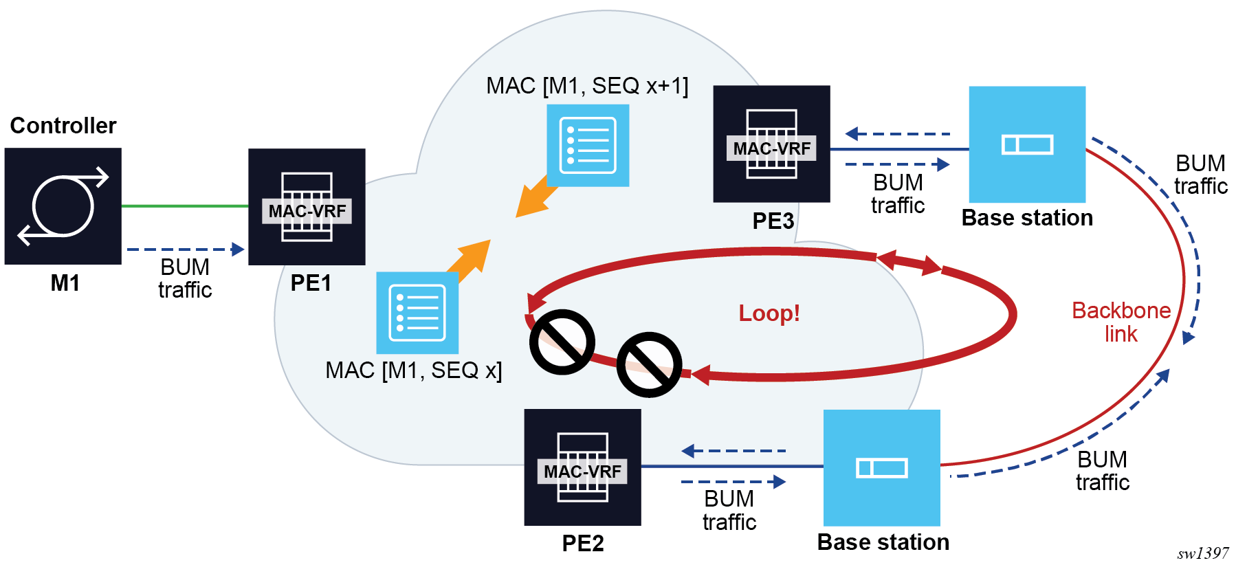
Assume PE1, PE2 and PE3 are attached to the same EVPN VPLS service, and there is an accidental backdoor link between the Base Stations connected to PE2 and PE3. When the Controller with MAC M1 issues a broadcast frame, PE1 forwards it to PE2 and PE3, and the frame is looped back via the backdoor link. The mac-duplication procedure kicks in and M1 is detected as duplicate and turned into a blackhole MAC in the FDB, effectively solving the loop. However, the user does not know beforehand if M1 is blackholed in PE1, PE2, PE3 or multiple of them at the same time. If M1 is blackholed in PE1, this represents an issue for the hosts connected to other PEs (not shown) attached to the same service. Therefore, in the example, we want to influence the mac-duplication procedure so that M1 gets blackholed in PE2, PE3, or both, but not in PE1. To make the procedure more deterministic, the Trusted MAC concept is used.
configure service vpls bgp-evpn mac-duplication trusted-mac-timeTrusted MACs are affected by the mac-duplication procedures in a different way from the non-trusted MACs. Trusted MACs require a different number of moves (during the mac-duplication window) to be declared as duplicate, specified by num-moves <number> * trusted-mac-move-factor <number> in the following context.
configure service vpls bgp-evpn mac-duplication detectWhile non-trusted MACs are detected as duplicate after num-moves, trusted MACs need more moves to be declared as duplicate.
The following example shows the configuration of three PEs, as shown in EVPN non-intrusive loop detection mechanism.
MD-CLI
// Applicable to PE1, PE2 and PE3

[ex:/configure service vpls "bd-1000" bgp-evpn mac-duplication]
A:admin@node-2# info
  blackhole true
  trusted-mac-time 5 // value 1..15, default: 5
  detect {
    num-moves 5
    window 3
    trusted-mac-move-factor 3 // value 1..10, default: 1
  }
classic CLI
// Applicable to PE1, PE2 and PE3

A:node-2>config>service>vpls>bgp-evpn>mac-duplication# info
----------------------------------------------
  detect num-moves 5 window 3 trusted-mac-move-factor 3 // value 1..10, default: 1
  black-hole-dup-mac
  trusted-mac-time 5 // value 1..15, default: 5
Based on the preceding configuration, recall the example described at the beginning of this section and assume M1 is a trusted MAC in PE1 (it has been dynamically learned for 5 minutes), then M1 requires 15 moves to be declared as duplicate (therefore a blackhole MAC) in PE1, whereas M1 only need 5 moves to be declared as duplicate in PE2 and PE3. This procedure guarantees that M1 does not get blackholed in the PE of its location (PE1).
The trusted MACs are shown in the following FDB show command example output with a "T" in the Type field.
show service id 1000 fdb detail===============================================================================
Forwarding Database, Service 1000
===============================================================================
ServId MAC Source-Identifier Type Last Change
Transport:Tnl-Id Age
-------------------------------------------------------------------------------
1000 00:de:fe:da:da:04 sap:1/1/1:1000 LT/0 05/18/23 10:54:54
-------------------------------------------------------------------------------
No. of MAC Entries: 1
-------------------------------------------------------------------------------
Legend:L=Learned O=Oam P=Protected-MAC C=Conditional S=Static Lf=Leaf T=Trusted
===============================================================================CFM interaction with EVPN services
Ethernet Connectivity and Fault Management (ETH-CFM) allows users to validate and measure Ethernet Layer 2 services using standard IEEE 802.1ag and ITU-T Y.1731 protocols. Each tool performs a unique function and adheres to that tool's specific PDU and frame format and the associate rules governing the transmission, interception, and process of the PDU. Detailed information describing the ETH-CFM architecture, the tools, and various functions is located in the various OAM and Diagnostics guides and is not repeated here.
EVPN provides powerful solution architectures. ETH-CFM is supported in Layer 2 EVPN architectures. Because the destination Layer 2 MAC address, unicast or multicast, is ETH-CFM tool dependent (that is, Ethernet continuity check (ETH-CC) is sent as a Layer 2 multicast and ETH-DM is sent as a Layer 2 unicast), the ETH-CFM function is allowed to multicast and broadcast to the virtual EVPN connections.
The MEP does not populate the local Layer 2 MAC address FDB with the MAC related to the MEP. This means that the 48-bit IEEE MAC address is not exchanged with peers, and all ETH-CFM frames are broadcast across all virtual connections. To prevent the flooding of unicast packets and allow the remote FDBs to learn the remote MEP Layer 2 MAC addresses, configure the cfm-mac-advertisement command under the config>service>vpls>bgp-evpn context. This allows the MEP Layer 2 IEEE MAC addresses to be exchanged with peers. This command tracks configuration changes and sends the required updates via the EVPN notification process related to a change.
Up MEP, Down MEP, and MIP creation is supported on the SAP, spoke, and mesh connections within the EVPN service. There is no support for the creation of ETH-CFM Management Points (MPs) on the virtual connection. VirtualMEP (vMEP) is supported with a VPLS context and the applicable EVPN Layer 2 VPLS solution architectures. The vMEP follows the same rules as the general MPs. When a vMEP is configured within the supported EVPN service, the ETH-CFM extraction routines are installed on the SAP, Binding, and EVPN connections within an EVPN VPLS Service. The vMEP extraction within the EVPN-PBB context requires the vmep-extensions parameter to install the extraction on the EVPN connections.
When MPs are used in combination with EVPN multihoming, observe the following considerations:
behavior of operationally down MEPs on SAPs or SDP-bindings with EVPN multihoming, as follows:
All-active multihoming
No ETH-CFM is expected to be used in this case, because the two (or more) SAPs/SDP-bindings on the PEs are oper-up and active; however, the CE has a single LAG and responds as though it is connected to a single system. In addition, the cfm-mac-advertisement command can lead to traffic loops in all-active multihoming.
Single-active multihoming
Operationally down MEPs defined on single-active ES SAPs or SDP-bindings do not send CCMs when the PE is non-DF for the ES and fault-propagation is configured. For single-active multihoming, the behavior is equivalent to MEPs defined on BGP-MH SAPs or binds.
behavior for operationally up MEPs on ES SAPs or SDP-bindings with EVPN multihoming, as follows:
All-active multihoming
Operationally up MEPs defined on non-DF ES SAPs can send CFM packets; however, they cannot receive CCMs (the SAP is removed from the default multicast list) or unicast CFM packets (because the MEP MAC is not installed locally in the FDB; unicast CFM packets are treated as unknown and not sent to the non-DF SAP MEP).
Single-active multihoming
Operationally up MEPs should be able to send or receive CFM packets normally.
Operationally up MEPs defined on LAG SAPs require the command process_cpm_traffic_on_sap_down so that they can process CFM when the LAG is down and act as regular Ethernet ports.
Because of the preceding considerations, Nokia recommends the use of ETH-CFM in EVPN multihomed SAPs or SDP-bindings only on operationally down MEPs and single-active multihoming, in which case ETH-CFM is used to notify the CE of the DF or non-DF status.
Multi-instance EVPN: Two instances of different encapsulation in the same VPLS/R-VPLS/Epipe service
SR OS supports a maximum of two BGP instances in the same VPLS or R-VPLS, where the two instances can be:
- one EVPN-VXLAN instance and one EVPN-MPLS instance in the same VPLS or R-VPLS service
- two EVPN-VXLAN instances in the same VPLS or R-VPLS service
- two EVPN-MPLS instances in the same VPLS or R-VPLS service
- one EVPN-MPLS instance and one EVPN-SRv6 instance in the same VPLS service
- one EVPN-VXLAN instance and one EVPN-SRv6 instance in the same VPLS service
In this case, the procedures are compliant with RFC 9014.
SR OS also supports up to two BGP instances in the same Epipe. These two instances can be an EVPN-MPLS instance and an EVPN-SRv6 instance in the same Epipe service.
The procedures to support two BGP instances in the same Epipe adhere to draft-sr-bess-evpn-vpws-gateway.
EVPN-VXLAN to EVPN-MPLS interworking
This section describes the configuration aspects of a VPLS/R-VPLS with EVPN-VXLAN and EVPN-MPLS.
In a service where EVPN-VXLAN and EVPN-MPLS are configured together, the configure service vpls bgp-evpn vxlan bgp 1 and configure service vpls bgp-evpn mpls bgp 2 commands allow the user to associate EVPN-MPLS to a different instance from that associated with EVPN-VXLAN, and have both encapsulations simultaneously enabled in the same service. At the control plane level, EVPN MAC/IP advertisement routes received in one instance are consumed and readvertised in the other instance as long as the route is the best route for a specific MAC. Inclusive multicast routes are independently generated for each BGP instance. In the data plane, the EVPN-MPLS and EVPN-VXLAN destinations are instantiated in different implicit Split Horizon Groups (SHGs) so that traffic can be forwarded between them.
The following example shows a VPLS service with two BGP instances and both VXLAN and MPLS encapsulations configured for the same BGP-EVPN service.
*A:PE-1>config>service>vpls# info
----------------------------------------------
  description "evpn-mpls and evpn-vxlan in the same service"
  vxlan instance 1 vni 7000 create
  exit
  bgp
    route-distinguisher 10:2
    route-target target:64500:1
  exit
  bgp 2
    route-distinguisher 10:1
    route-target target:64500:1
  exit
  bgp-evpn
    evi 7000
    incl-mcast-orig-ip 10.12.12.12
    vxlan bgp 1 vxlan-instance 1
      no shutdown
    mpls bgp 2
      control-word
      auto-bind-tunnel
        resolution any
      exit
      force-vlan-vc-forwarding
      no shutdown
    exit
  exit
  no shutdown
The following list describes the preceding example:
-
bgp 1 or bgp is the default BGP instance
-
bgp 2 is the additional instance required when both bgp-evpn vxlan and bgp-evpn mpls are enabled in the service
-
The commands supported in instance 1 are also available in instance 2 with the following considerations:
-
pw-template-binding
The pw-template-binding can only exist in instance 1; it is not supported in instance 2.
-
route-distinguisher
The operating route-distinguisher in both BGP instances must be different.
-
route-target
The route target in both instances can be the same or different.
-
vsi-import and vsi-export
Import and export policies can also be defined for either BGP instance.
-
-
MPLS and VXLAN can use either BGP instance, and the instance is associated when bgp-evpn mpls or bgp-evpn vxlan is created. The bgp-evpn vxlan command must include not only the association to a BGP instance, but also to a vxlan-instance (because the VPLS services support two VXLAN instances).
Note: The bgp-evpn vxlan no shutdown command is only allowed if bgp-evpn mpls shutdown is configured, or if the BGP instance associated with the MPLS has a different route distinguisher than the VXLAN instance.
The following features are not supported when two BGP instances are enabled on the same VPLS/R-VPLS service:
-
SDP bindings
-
M-VPLS, I-VPLS, B-VPLS, or E-Tree VPLS
-
Proxy-ARP and proxy-ND
-
BGP Multihoming
-
IGMP, MLD, and PIM snooping
-
BGP-VPLS or BGP-AD (SDP bindings are not created)
The service>vpls>bgp-evpn>ip-route-advertisement command is not supported on R-VPLS services with two BGP instances.
EVPN-SRv6 to EVPN-MPLS or EVPN-VXLAN interworking
EVPN-SRv6 and EVPN-MPLS or EVPN-VXLAN can be simultaneously configured in the same VPLS service (but not R-VPLS), in different instances. In addition, EVPN-SRv6 and EVPN-MPLS can be simultaneously configured in the same Epipe service, so that border routers can stitch SRv6 and MPLS domains for point-to-point services.
VPLS services
EVPN-SRv6 and EVPN-VXLAN instances in the same VPLS service follow the same configuration rules as described in EVPN-VXLAN to EVPN-MPLS interworking, and the same processing of MAC/IP Advertisement routes and Inclusive Multicast Ethernet Tag routes is applied.
The following example shows a VPLS service with two BGP instances, with both VXLAN and SRv6 encapsulations configured under BGP-EVPN.
MD-CLI
A:node-2>config>service>vpls "evpn-srv6-vxlan-1"> info
    admin-state enable
    description "evpn-srv6 and evpn-vxlan in the same service"
    vxlan {
        instance 1 {
            vni 12340
        }
    }
    segment-routing-v6 1 {
        locator "loc-1" {
            function {
                end-dt2u {
                }
                end-dt2m {
                }
            }
        }
    }
    bgp 1 {
        route-distinguisher "12340:1"
        route-target {
            export "target:64500:12340"
            import "target:64500:12340"
        }
    }
    bgp 2 {
        route-distinguisher "12340:2"
        route-target {
            export "target:64500:12341"
            import "target:64500:12341"
        }
    }
    bgp-evpn {
        evi 12340
        incl-mcast-orig-ip 10.12.12.12
        segment-routing-v6 2 {
            admin-state enable
            ecmp 4
            force-vc-forwarding vlan
            srv6 {
                default-locator "loc-1"
            }
        }
        vxlan 1 {
            admin-state enable
            vxlan-instance 1
        }
    }
classic CLI
A:node-2>config>service>vpls# info
----------------------------------------------
            description "evpn-srv6 and evpn-vxlan in the same service"
            vxlan instance 1 vni 12340 create
            exit
            segment-routing-v6 1 create
                locator "loc-1"
                    function
                        end-dt2u
                        end-dt2m
                    exit
                exit
            exit
            bgp
                route-distinguisher 12340:1
                route-target export target:64500:12340 import target:64500:12340
            exit
            bgp 2
                route-distinguisher 12340:2
                route-target export target:64500:12341 import target:64500:12341
            exit
            bgp-evpn
                incl-mcast-orig-ip 10.12.12.12
                evi 12340
                vxlan bgp 1 vxlan-instance 1
                    no shutdown
                exit
                segment-routing-v6 bgp 2 srv6-instance 1 default-locator "loc-1" create
                    ecmp 4
                    force-vlan-vc-forwarding
                    route-next-hop 2001:db8::76
                    no shutdown
                exit
            exit
            stp
                shutdown
            exit
            no shutdown
----------------------------------------------
When an EVPN-SRv6 instance and an EVPN-MPLS instance are both configured in the same VPLS service, each instance can be configured in a different or the same split horizon group. The former option allows the interconnection of domains of different encapsulation, and the rules of configuration and route processing described in EVPN-VXLAN to EVPN-MPLS interworking apply. The latter option is used for domains where MPLS and SRv6 PEs are attached to the same service, typically for migration purposes.
When the EVPN-SRv6 and the EVPN-MPLS instances are configured in the same split horizon group:
- MAC/IP Advertisement routes are not redistributed between the two instances
- Two BUM EVPN destinations to the same far-end PE (identified by the originator IP of the Inclusive Multicast Ethernet Tag routes) cannot be created. An EVPN-MPLS BUM destination is removed if there is another BUM destination to the same far end with an SRv6 encapsulation. This is to prevent BUM traffic duplication between multi-instance nodes
- SAPs are supported, but SDP binds are not supported
The following example shows a VPLS service with two BGP instances, with both MPLS and SRv6 encapsulations configured under BGP-EVPN, with the same split horizon group.
MD-CLI
configure service vpls "evpn-srv6-mpls-1" >info
admin-state enable
    description "evpn-srv6 and evpn-mpls in the same service"
    segment-routing-v6 1 {
        locator "loc-1" {
            function {
                end-dt2u {
                }
                end-dt2m {
                }
            }
        }
    }
    bgp 1 {
        route-distinguisher "12341:1"
        route-target {
            export "target:64500:12342"
            import "target:64500:12342"
        }
    }
    bgp 2 {
        route-distinguisher "12341:2"
        route-target {
            export "target:64500:12343"
            import "target:64500:12343"
        }
    }
    bgp-evpn {
        evi 12340
        incl-mcast-orig-ip 10.12.12.12
        segment-routing-v6 2 {
            admin-state enable
            ecmp 4
            force-vc-forwarding vlan
            srv6 {
                default-locator "loc-1"
            }
            route-next-hop {
                ip-address 2001:db8::76
            }
        }
        mpls 1 {
            admin-state enable
            force-vc-forwarding vlan
            split-horizon-group "SHG-1"
            ingress-replication-bum-label true
            ecmp 4
            mh-mode access
            auto-bind-tunnel {
                resolution any
            }
        }
    }
    split-horizon-group "SHG-1" {
    }
classic CLI
A:node-2>config>service>vpls# info
----------------------------------------------
            description "evpn-srv6 and evpn-mpls in the same service"
            split-horizon-group "SHG-1" create
            exit
            segment-routing-v6 1 create
                locator "loc-1"
                    function
                        end-dt2u
                        end-dt2m
                    exit
                exit
            exit
            bgp
                route-distinguisher 12341:1
                route-target export target:64500:12342 import target:64500:12342
            exit
            bgp 2
                route-distinguisher 12341:2
                route-target export target:64500:12343 import target:64500:12343
            exit
            bgp-evpn
                incl-mcast-orig-ip 10.12.12.12
                evi 12341
                mpls bgp 1
                    mh-mode access
                    force-vlan-vc-forwarding
                    split-horizon-group "SHG-1"
                    ingress-replication-bum-label
                    ecmp 4
                    auto-bind-tunnel
                        resolution any
                    exit
                    no shutdown
                exit
                segment-routing-v6 bgp 2 srv6-instance 1 default-locator "loc-1" create
                    ecmp 4
                    force-vlan-vc-forwarding
                    route-next-hop 2001:db8::76
                    split-horizon-group "SHG-1"
                    no shutdown
                exit
            exit
            stp
                shutdown
            exit
            no shutdown
----------------------------------------------
Epipe services
The following example shows an Epipe service with two BGP instances, with both MPLS and SRv6 encapsulations configured under BGP-EVPN. This is the gateway configuration when it is stitching MPLS and SRv6 domains for E-Line services.
MD-CLI
[ex:/configure service epipe "multi-inst-evpn-vpws-100"]
A:admin@node-2# info
    admin-state enable
    service-id 100
    customer "1"
    segment-routing-v6 1 {
        locator "LOC-2-16bits" {
            function {
                end-dx2 {
                }
            }
        }
    }
    bgp 1 {
        route-distinguisher "23.23.23.1:100"
    }
    bgp 2 {
        route-distinguisher "23.23.23.2:100"
    }
    endpoint "mpls" {
    }
    endpoint "srv6" {
    }
    bgp-evpn {
        evi 100
        local-attachment-circuit "mpls" {
            endpoint "mpls"
            eth-tag 1
        }
        local-attachment-circuit "srv6" {
            endpoint "srv6"
            eth-tag 1
            bgp 2
        }
        remote-attachment-circuit "mpls" {
            endpoint "mpls"
            eth-tag 1
        }
        remote-attachment-circuit "srv6" {
            endpoint "srv6"
            eth-tag 1
            bgp 2
        }
        mpls 1 {
            admin-state enable
            ecmp 2
            domain-id "64500:1"
            auto-bind-tunnel {
                resolution any
            }
        }
        segment-routing-v6 2 {
            admin-state enable
            source-address 2001:db8::2
            mh-mode access
            domain-id "64500:2"
            srv6 {
                instance 1
                default-locator "LOC-2-16bits"
            }
        }
    }
classic CLI
A:node-2# configure service epipe 100
A:node-2>config>service>epipe# info
----------------------------------------------
            endpoint "mpls" create
            exit
            endpoint "srv6" create
            exit
            segment-routing-v6 1 create
                locator "LOC-2-16bits"
                    function
                        end-dx2
                    exit
                exit
            exit
            bgp 1
                route-distinguisher 23.23.23.1:100
            exit
            bgp 2
                route-distinguisher 23.23.23.2:100
            exit
            bgp-evpn
                local-attachment-circuit mpls bgp 1 endpoint mpls create
                    eth-tag 1
                exit
                local-attachment-circuit srv6 bgp 2 endpoint srv6 create
                    eth-tag 1
                exit
                remote-attachment-circuit mpls bgp 1 endpoint mpls create
                    eth-tag 1
                exit
                remote-attachment-circuit srv6 bgp 2 endpoint srv6 create
                    eth-tag 1
                exit
                evi 100
                mpls bgp 1
                    domain-id 64500:1
                    ecmp 2
                    auto-bind-tunnel
                        resolution any
                    exit
                    no shutdown
                exit
                segment-routing-v6 bgp 2 srv6-instance 1 default-locator "LOC-2-16bits" create
                    domain-id 64500:2
                    mh-mode access
                    source-address 2001:db8::2
                    no shutdown
                exit
            exit
            no shutdown
----------------------------------------------- The epipe bgp command supports up to two instances, where the default value is 1, and the accepted values are now in the range 1..2.
- The bgp-instance of 1 or 2 can be matched under the
following
contexts:
MPLS and SRv6 can be configured in Epipes with one or two instances, and they can indistinctly use instance “1” or “2”. The preceding example shows an Epipe service with MPLS configured in bgp-instance 1 and segment-routing-v6 configured in bgp-instance 2.configure service epipe bgp-evpn mpls configure service epipe bgp-evpn segment-routing-v6 - The bgp-instance 2 requires the support of the explicit route distinguisher (RD) configuration because the EVI-based autoderivation of the RD only applies to bgp-instance 1. The route target EVI-based autoderivation applies to both instances.
- The following command can also be associated with a BGP instance.
By default, all local attachment circuits in the service are associated with bgp-instance 1. When the local attachment circuits are associated with different BGP instances, no local SAPs or spoke-SDPs are supported in the service (this is blocked by the CLI).configure service epipe bgp-evpn local-attachment-circuit - The BGP instances are configured with a D-PATH domain-id. The D-PATH attribute is described in section BGP D-PATH attribute for Layer 3 loop protection and can also be used in multi-instance Epipe services. D-PATH is used in the EVPN-VPWS AD per-EVI routes for best-path selection and loop avoidance in case of redundant gateways. In the preceding example, configuring segment-routing-v6 bgp 2 domain-id 64500:2 means that the received EVPN AD per-EVI route in the SRv6 instance is redistributed to the MPLS instance with a D-PATH attribute where domain 64500:2 is prepended.
- When configuring an SRv6 and an MPLS instance in an Epipe service, one of the two instances must be configured as mh-mode access, with the other one configured as mh-mode network (default value for SRv6 and MPLS instances). The command is added under the MPLS and SRv6 instances (not in VXLAN instances).
As in the case of any Epipe service, two explicit or implicit endpoints exist, where traffic always flows from one endpoint to the other endpoint. The preceding example uses the configuration of two explicit endpoints, however one implicit endpoint plus one explicit endpoint can also be configured, and the behavior would be identical. In other words, the preceding configuration is also valid if the endpoint "mpls" is not configured. In this case, the local-attachment-circuit and remote-attachment-circuit associated with bgp 1 would be part of an implicit end-point.
BGP-EVPN routes in services configured with two BGP instances
The following sections describe BGP-EVPN routes in EVPN and VPLS services configured with two BGP instances.
VPLS services
From a BGP perspective, the two BGP instances configured in the service are independent of each other. The redistribution of routes between the BGP instances is resolved at the EVPN application layer.
By default, if EVPN-VXLAN and EVPN-MPLS are both enabled in the same service, BGP sends the generated EVPN routes twice: with the RFC 9012 BGP encapsulation extended community set to VXLAN and a second time with the encapsulation type set to MPLS.
Usually, a DCGW peers a pair of Route Reflectors (RRs) in the DC and a pair of RRs in the WAN. For this reason, the user needs to add router policies so that EVPN-MPLS routes are only sent to the WAN RRs and EVPN-VXLAN routes are only sent to the DC RRs. The following examples show how to configure router policies.
MD-CLI
[ex:/configure router "Base" bgp]
A:admin@node-2# info
    vpn-apply-export true
    vpn-apply-import true
    group "WAN" {
        type internal
        family {
            evpn true
        }
        export {
            policy ["allow only mpls"]
        }
    }
    group "DC" {
        type internal
        family {
            evpn true
        }
        export {
            policy ["allow only vxlan"]
        }
    }
    neighbor "192.0.2.2" {
        group "WAN"
    }
    neighbor "192.0.2.75" {
        group "DC"
    }

*[ex:/configure policy-options]
A:admin@PE-76# info
    community "mpls" {
        member "bgp-tunnel-encap:MPLS" { }
    }
    community "vxlan" {
        member "bgp-tunnel-encap:VXLAN" { }
    }
    policy-statement "allow only mpls" {
        entry 10 {
            from {
                family [evpn]
                community {
                    name "vxlan"
                }
            }
            action {
                action-type reject
            }
        }
    }
    policy-statement "allow only vxlan" {
        entry 10 {
            from {
                family [evpn]
                community {
                    name "mpls"
                }
            }
            action {
                action-type reject
            }
        }
    }
classic CLI
config>router>bgp#
 vpn-apply-import
 vpn-apply-export
 group "WAN"
  family evpn
  type internal
  export "allow only mpls"
  neighbor 192.0.2.6
 group "DC"
  family evpn
  type internal
  export "allow only vxlan"
  neighbor 192.0.2.2
A:node-2>config>router>policy-options# info
----------------------------------------------
community "vxlan" members "bgp-tunnel-encap:VXLAN"
community "mpls" members "bgp-tunnel-encap:MPLS"
policy-statement "allow only mpls"
entry 10
from
family evpn
community vxlan
action drop
exit
exit
exit
policy-statement "allow only vxlan"
entry 10
from
family evpn
community mpls
action drop
exit
exit
exit
In a BGP instance, the EVPN routes are imported based on the route-targets and regular BGP selection procedures, regardless of their encapsulation.
The BGP-EVPN routes are generated and redistributed between BGP instances based on the following rules:
-
Auto-discovery (AD) routes (type 1) are not generated by services with two BGP EVPN instances, unless a local Ethernet segment is present on the service. However, AD routes received from the EVPN-MPLS peers are processed for aliasing and backup functions as usual.
-
MAC/IP routes (type 2) received in one of the two BGP instances are imported and the MACs added to the FDB according to the existing selection rules. If the MAC is installed in the FDB, it is readvertised in the other BGP instance with the new BGP attributes corresponding to the BGP instance (route target, route distinguisher, and so on). The following considerations apply to these routes:
-
The mac-advertisement command governs the advertisement of any MACs (even those learned from BGP).
-
A MAC route is redistributed only if it is the best route based on the EVPN selection rules.
-
If a MAC route is the best route and has to be redistributed, the MAC/IP information, along with the MAC mobility extended community, is propagated in the redistribution.
-
The router redistributes any MAC route update for which any attribute has changed. For example, a change in the SEQ or sticky bit in one instance is updated in the other instance for a route that is selected as the best MAC route.
-
-
EVPN inclusive multicast routes are generated independently for each BGP instance with the corresponding BGP encapsulation extended community (VXLAN or MPLS). Also, the following considerations apply to these routes:
-
Ingress Replication (IR) and Assisted Replication (AR) routes are supported in the EVPN-VXLAN instance. If AR is configured, the AR IP address must be a loopback address different from the system-ip and the configured originating-ip address.
-
IR, P2MP mLDP, and composite inclusive multicast routes are supported in the EVPN-MPLS instance.
-
The modification of the incl-mcast-orig-ip command is supported, subject to the following considerations:
-
The configured IP in the incl-mcast-orig-ip command is encoded in the originating-ip field of the inclusive multicast Routes for IR, P2MP, and composite tunnels.
-
The originating-ip field of the AR routes is still derived from the service>system>vxlan>assisted-replication-ip configured value.
-
-
EVPN handles the inclusive multicast routes in a service based on the following rules:
-
For IR routes, the EVPN destination is set up based on the NLRI next hop.
-
For P2MP mLDP routes, the PMSI Tunnel Attribute tunnel-id is used to join the mLDP tree.
-
For composite P2MP-IR routes, the PMSI Tunnel Attribute tunnel-id is used to join the tree and create the P2MP bind. The NLRI next-hop is used to build the IR destination.
-
For AR routes, the NLRI next-hop is used to build the destination.
-
The following applies if a router receives two inclusive multicast routes in the same instance:
-
If the routes have the same originating-ip but different route distinguishers and next-hops, the router processes both routes. In the case of IR routes, it sets up two destinations: one to each next-hop.
-
If the routes have the same originating-ip, different route distinguishers, but same next hops, the router sets up only one binding for IR routes.
-
The router ignores inclusive multicast routes received with its own originating-ip, regardless of the route distinguisher.
-
-
-
-
IP-Prefix routes (type 5) are not generated or imported by a service with two BGP instances.
The rules in this section can be extrapolated to VPLS services where SRv6 and MPLS or VXLAN are configured in different instances of the same VPLS with different split horizon groups.
Epipe services
- Upon receiving an AD per-EVI route in bgp-instance 1, if the route is selected to be installed and the route does not contain a local domain-id in its D-PATH attribute (local means the domain-id is configured in the Epipe), an AD per-EVI route is triggered in bgp-instance 2, using the eth-tag, RD, RT and properties of bgp-instance 2.
- The EVPN Layer 2 attributes extended community is regenerated for the redistributed route. The value of the P and B flags is set to 0 when redistributing routes.
- The encapsulation-specific attributes of the redistributed route are regenerated based on the encapsulation of the BGP instance in which the route is advertised.
- The redistributed route carries the Communities, Extended Communities, and Large
Communities of the source route when the following command is configured:
- MD-CLI
configure service system bgp evpn ad-per-evi-routes attribute-propagation true - classic-CLI
configure service system bgp-evpn ad-per-evi-routes attribute-propagation
- MD-CLI
The exception are RTs (which are re-originated), EVPN Extended Communities, and BGP Encapsulation Extended Communities [RFC 9012]. EVPN Extended Communities and BGP Encapsulation Extended Communities are not propagated across domains.
- The redistributed AD per-EVI route updates the D-PATH attribute of the received route or adds the D-PATH attribute if the received route did not contain a D-PATH.
- The ESI of the redistributed AD per-EVI route is always zero.
- AD per-ES and ES routes are never redistributed.
Route selection of AD per-EVI routes
The redistribution of attributes, as well as the BGP best-path selection for AD per-EVI routes is controlled by the commands shown in the following examples.
MD-CLI
[ex:/configure service system bgp evpn ad-per-evi-routes]
A:admin@PE-2# tree detail
+-- attribute-propagation <boolean>
+-- bgp-path-selection <boolean>
+-- d-path-ignore <boolean>
Classic CLI
*A:PE-2>config>service>system>bgp-evpn>ad-per-evi-routes# tree detail
ad-per-evi-routes
|
+---attribute-propagation
| no attribute-propagation
|
+---bgp-path-selection
| no bgp-path-selection
|
+---d-path-ignore
| no d-path-ignore
Where both (bgp-path-selection and attribute-propagation) are disabled by default, and the router enforces that bgp-path-selection can only be enabled if attribute-propagation is enabled before.
If bgp-path-selection false (default) is configured, in case of multiple AD per-EVI routes for the same Ethernet tag are received in the same Epipe BGP instance, the lowest IP route is selected. Those routes may have zero ESI, or different non-zero ESI.
When multiple non-zero ESI AD per-EVI routes are received and the ESI matches on all of them, the bgp-path-selection command impacts the following procedures:
- The command influences the selection of AD per-EVI routes to create the ES destination. If disabled, the lowest IP address routes are selected, up to the number of configured ECMP paths. If enabled, the routes are selected based on BGP best-path selection.
- The command influences the selection of the best AD per-EVI route of the ES for the purpose of attribute propagation. If enabled, the attributes of the best-path route are propagated.
- High Local Pref wins
- Shortest D-PATH wins (if
d-path-ignore
                            false
) - Lowest left-most D-PATH domain-id wins (if
d-path-ignore false) - Shortest AS_PATH wins
- Lowest Origin wins
- Lowest MED wins
- EBGP wins
- Lowest tunnel-table cost to the next-hop
- Lowest next-hop type wins (resolution in TTM wins vs RTM)
- Lowest next-hop type wins
- Lowest router ID wins (applicable to ibgp peers only)
- Shortest cluster_list length wins (applicable to ibgp peers only)
- Lowest IP address
- Next-hop check (IPv4 NH wins, then lowest NH wins)
- RD check (lowest RD wins)
- Path-Id (add path)
Anycast redundant solution for dual BGP-instance services
The following sections describe the anycast redundant solution for dual BGP instances in VPLS and Epipe services.
VPLS services
The following figure shows the anycast mechanism used to support gateway redundancy for dual BGP-instance services. The example shows two redundant DC gateways (DCGWs) where the VPLS services contain two BGP instances: one each for EVPN-VXLAN and EVPN-MPLS.
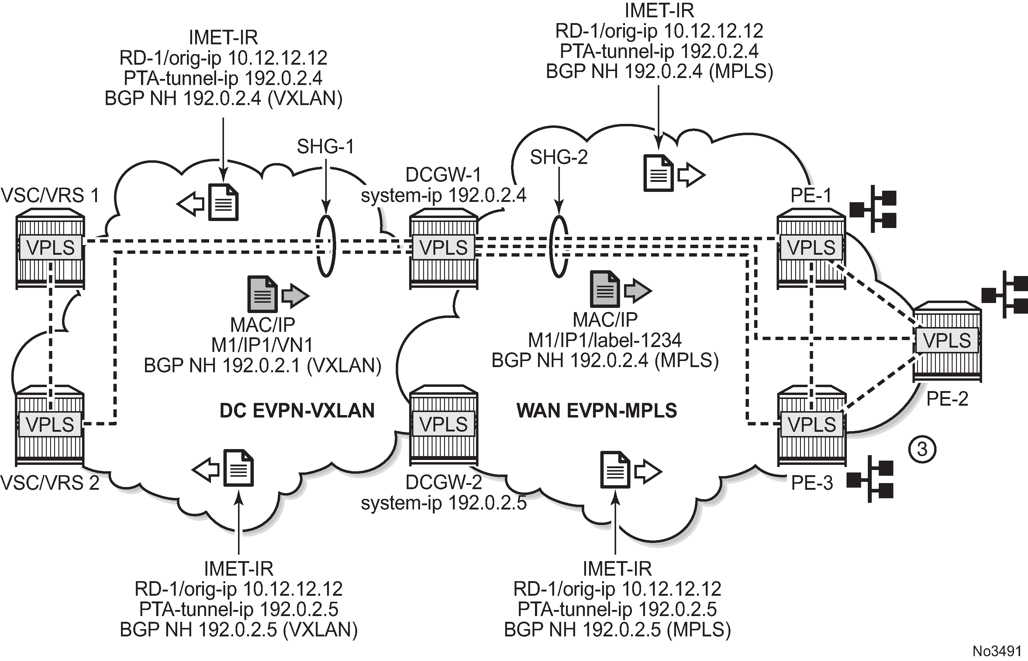
The example shown in Multihomed anycast solution depends on the ability of the two DCGWs to send the same inclusive multicast route to the remote PE or NVEs, such that:
-
The remote PE or NVEs create a single BUM destination to one of the DCGWs (because the BGP selects only the best route to the DCGWs).
-
The DCGWs do not create a destination between each other.
This solution avoids loops for BUM traffic, and known unicast traffic can use either DCGW router, depending on the BGP selection. The following CLI example output shows the configuration of each DCGW.
MD-CLI
/* bgp configuration on DCGW1 and DCGW2 */

[ex:/configure router "Base" bgp]
A:admin@DCGW# info
    vpn-apply-export true
    vpn-apply-import true
    group "DC" {
        type internal
        family {
            evpn true
        }
    }
    group "WAN" {
        type internal
        family {
            evpn true
        }
    }
    neighbor "192.0.2.2" {
        group "DC"
    }
    neighbor "192.0.2.6" {
        group "WAN"
    }

/* vpls service configuration in DCGW1 */

[ex:/configure service vpls "1"]
A:admin@DCGW1# info
    admin-state enable
    customer "1"
    vxlan {
        instance 1 {
            vni 1
        }
    }
    bgp 1 {
        route-distinguisher "64501:12"
        route-target {
            export "target:64500:1"
            import "target:64500:1"
        }
    }
    bgp 2 {
        route-distinguisher "64502:12"
        route-target {
            export "target:64500:1"
            import "target:64500:1"
        }
    }
    bgp-evpn {
        evi 1
        incl-mcast-orig-ip 10.12.12.12
        vxlan 1 {
            admin-state enable
            vxlan-instance 1
        }
        mpls 2 {
            admin-state enable
            auto-bind-tunnel {
                resolution any
            }
        }
    }

/* vpls service configuration in DCGW2 */

[ex:/configure service vpls "1"]
A:admin@DCGW2# info
    admin-state enable
    customer "1"
    vxlan {
        instance 1 {
            vni 1
        }
    }
    bgp 1 {
        route-distinguisher "64501:12"
        route-target {
            export "target:64500:1"
            import "target:64500:1"
        }
    }
    bgp 2 {
        route-distinguisher "64502:12"
        route-target {
            export "target:64500:1"
            import "target:64500:1"
        }
    }
    bgp-evpn {
        evi 1
        incl-mcast-orig-ip 10.12.12.12
        vxlan 1 {
            admin-state enable
            vxlan-instance 1
        }
        mpls 2 {
            admin-state enable
            auto-bind-tunnel {
                resolution any
            }
        }
    }
classic CLI
/* bgp configuration on DCGW1 and DCGW2 */
config>router>bgp#
 group ”WAN"
  family evpn
  type internal
  neighbor 192.0.2.6
 group ”DC"
  family evpn
  type internal
  neighbor 192.0.2.2
/* vpls service configuration */
DCGW-1# config>service>vpls(1)#
-----------------------
bgp
  route-distinguisher 64501:12
  route-target target:64500:1
exit
bgp 2
  route-distinguisher 64502:12
  route-target target:64500:1
exit
vxlan instance 1 vni 1 create
exit
bgp-evpn
  evi 1
  incl-mcast-orig-ip 10.12.12.12
  vxlan bgp 1 vxlan-instance 1
   no shutdown
  mpls bgp 2
   no shutdown
   auto-bind-tunnel
     resolution any
   exit
<snip>
DCGW-2# config>service>vpls(1)#
-----------------------
bgp
  route-distinguisher 64501:12
  route-target target:64500:1
exit
bgp 2
  route-distinguisher 64502:12
  route-target target:64500:1
exit
vxlan instance 1 vni 1 create
exit
bgp-evpn
  evi 1
  incl-mcast-orig-ip 10.12.12.12
  vxlan bgp 1 vxlan-instance 1
   no shutdown
  mpls bgp 2
   no shutdown
   auto-bind-tunnel
     resolution any
<snip>
Based on the preceding configuration example, the behavior of the DCGWs in this scenario is as follows:
-
DCGW-1 and DCGW-2 send inclusive multicast routes to the DC RR and WAN RR with the same route key. For example:
-
DCGW-1 and DCGW-2 both send an IR route to DC RR with RD=64501:12, orig-ip=10.12.12.12, and a different next hop and tunnel ID
-
DCGW-1 and DCGW-2 both send an IR route to WAN RR with RD=64502:12, orig-ip=10.12.12.12, and different next hop and tunnel ID
-
-
DCGW-1 and DCGW-2 both receive MAC/IP routes from DC and WAN that are redistributed to the other BGP instances, assuming that the route is selected as best route and the MAC is installed in the FDB.
As described in section BGP-EVPN routes in services configured with two BGP instances, router peer policies are required so that only VXLAN or MPLS routes are sent or received for a specific peer.
-
Configuration of the same incl-mcast-orig-ip address in both DCGWs enables the anycast solution for BUM traffic for all the following reasons:
-
The configured originating-ip is not required to be a reachable IP address and this forces the remote PE or NVEs to select only one of the two DCGWs.
-
The BGP next hops are allowed to be the system-ip or even a loopback address. In both cases, the BGP next hops are not required to be reachable in their respective networks.
-
In the example shown in Multihomed anycast solution, PE-1 picks up DCGW-1's inclusive multicast route (because of its lower BGP next hop) and creates a BUM destination to 192.0.2.4. When sending BUM traffic for VPLS-1, it only sends the traffic to DCGW-1. In the same way, the DCGWs do not set up BUM destinations between each other as they use the same originating-ip in their inclusive multicast routes.
The remote PE or NVEs perform a similar BGP selection for MAC/IP routes, as a specific MAC is sent by the two DCGWs with the same route key. A PE or NVE sends known unicast traffic for a specific MAC to only one DCGW.
Epipe services
The anycast redundancy solution can also be used for gateways that stitch SRv6 to MPLS domains for EVPN-VPWS services. The principle is similar to the one described in VPLS services. The following figure shows an example.
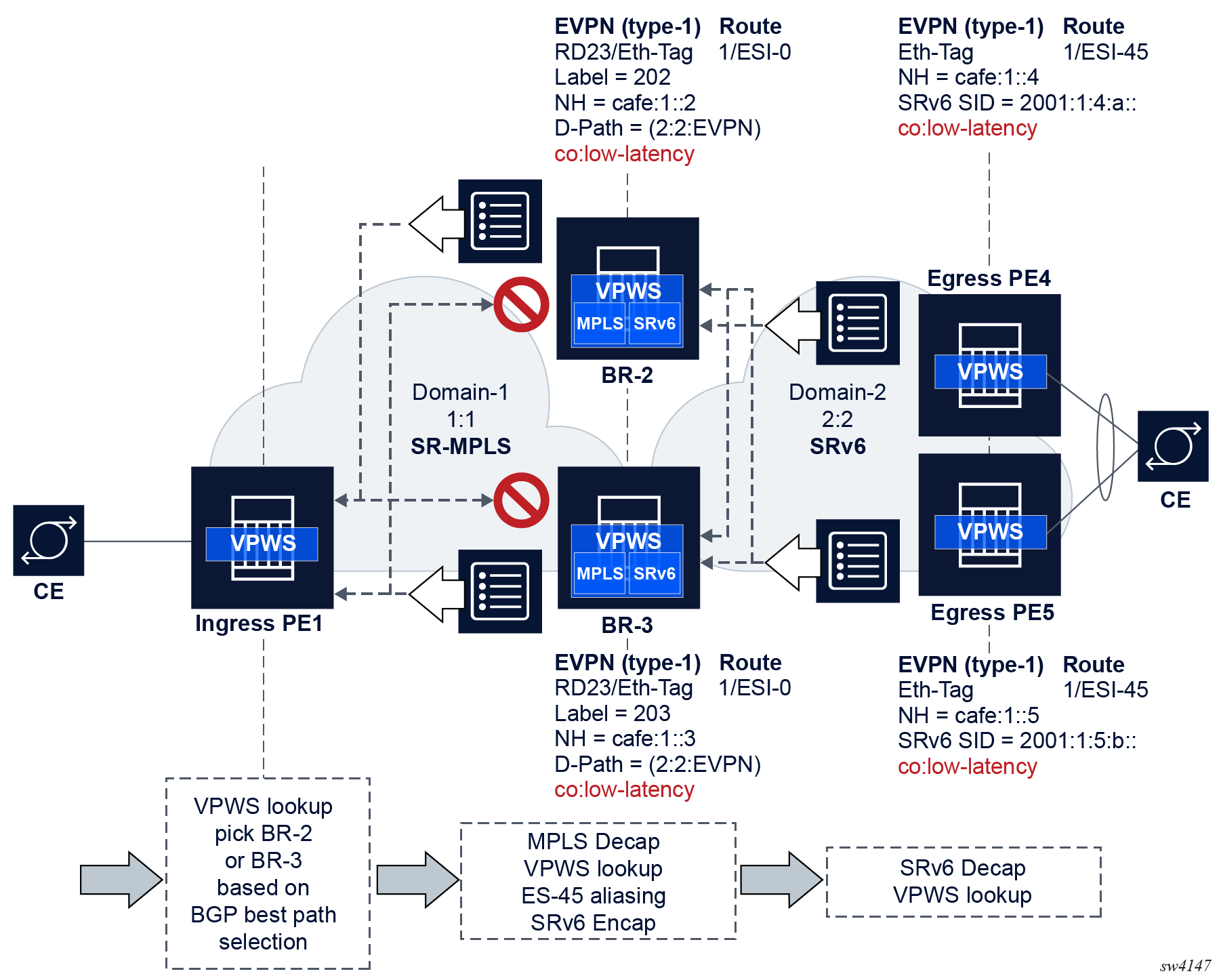
The configuration on the two gateways (BR-2 and BR-3 in the preceding example) must generate AD per-EVI routes with the same route key (including the same RD) from both gateways so that the ingress PEs select one of the two gateways based on BGP best-path selection.
The following is an example of the (identical) configuration in BR-2 and BR-3.
MD-CLI
[ex:/configure service epipe "1"]
A:admin@BR-2/BR-3# info
    admin-state enable
    service-id 1
    customer "1"
    segment-routing-v6 1 {
        locator "LOC-1" {
            function {
                end-dx2 {
                }
            }
        }
    }
    bgp 1 {
	route-distinguisher 2323:1
    }
    bgp 2 {
    	route-distinguisher 2323:2
    }
    endpoint "MPLS" {
    }
    endpoint "SRv6" {
    }
    bgp-evpn {
        evi 1
        local-attachment-circuit "gw-mpls" { // implicitly associated to bgp 1
        	eth-tag 1
		endpoint “MPLS”
        }
        remote-attachment-circuit "ac-1-mpls" {
            	eth-tag 1
		endpoint “MPLS”
        }
        local-attachment-circuit "gw-srv6" {  // associated to bgp 2
        	eth-tag 1
		endpoint “SRv6”
		bgp 2
        }
        remote-attachment-circuit "ac-2-srv6" {
            	eth-tag 1
		endpoint “SRv6”
               bgp 2
        }
        mpls 1 {
            admin-state enable
            ecmp 2
            domain 64500:1
            mh-mode access
            auto-bind-tunnel {
                resolution any
            }
            route-next-hop {
                ip-address 2001:db8::2
            }
        }
     	segment-routing-v6 2 {
            admin-state enable
            source-address 2001:db8::2
            ecmp 2
            domain 64500:2
            mh-mode network // default
            srv6 {
                instance 1
                default-locator "LOC-1"
            }
            route-next-hop {
                system-ipv6
            }
        }
    }
classic CLI
*A:BR-2/BR-3# configure service epipe 1
*A:BR-2/BR-3>config>service>epipe# info
----------------------------------------------
            endpoint "MPLS" create
            exit
            endpoint "SRv6" create
            exit
            segment-routing-v6 1 create
                locator "LOC-1"
                    function
                        end-dx2
                    exit
                exit
            exit
            bgp 1
                route-distinguisher 2323:1
            exit
            bgp 2
                route-distinguisher 2323:2
            exit
            bgp-evpn
                local-attachment-circuit "gw-mpls" bgp 1 endpoint "MPLS" create
                    eth-tag 1
                exit
                local-attachment-circuit "gw-srv6" bgp 2 endpoint "SRv6" create
                    eth-tag 1
                exit
                remote-attachment-circuit "ac-1-mpls" bgp 1 endpoint "MPLS" create
                    eth-tag 1
                exit
                remote-attachment-circuit "ac-2-srv6" bgp 2 endpoint "SRv6" create
                    eth-tag 1
                exit
                evi 1
                mpls bgp 1
                    domain-id 64500:1
                    ecmp 2
                    auto-bind-tunnel
                        resolution any
                    exit
                    no shutdown
                exit
                segment-routing-v6 bgp 2 srv6-instance 1 default-locator "LOC-1" create
                    domain-id 64500:2
                    mh-mode access
                    source-address 2001:db8::3
                    no shutdown
                exit
            exit
            no shutdown
----------------------------------------------
In this example:
- The anycast gateways attached to the same two domains redistribute the EVPN AD per-EVI routes between domains, where ESI is always reset to zero.
- The redundant gateways may set the same Ethernet Tag ID in the redistributed A-D per-EVI route (the example shows the same eth-tag values, but the gateways could also use other values).
- The anycast gateways process the received D-PATH attribute and update the D-PATH (with the source domain ID) when redistributing the AD per-EVI route to the next domain. The D-PATH attribute avoids control plane loops.
The following considerations related to the use of D-PATH in this configuration apply:
- Based on the domain configuration, when an AD per-EVI route is imported in domain X and redistributed into domain Y, the domain ID of X is prepended to the D-PATH in the redistributed AD per-EVI route.
- When two AD per-EVI routes for the same and Ethernet tag (same route key) are received on the same services from different next hops, D-PATH is considered in the BGP best-path selection, unless d-path-ignore true is configured.
- When two AD per-EVI routes for the same service are received with different RDs and the same Ethernet tag from different next hops, D-PATH is considered in the BGP best-path selection, unless d-path-ignore true is configured, and assuming bgp-path-selection true is configured.
- If d-path-ignore false is configured, the router compares
the D-PATH attribute received in VPWS AD per-EVI routes with the same key
(same or different RDs) as follows:
- The routes with the shortest D-PATH are preferred, therefore routes not tied to the shortest D-PATH are removed. Routes without D-PATH are considered zero-length D-PATH.
- The routes with the numerically lowest left-most domain ID are preferred, therefore routes not tied to the numerically lowest left-most domain ID are removed from consideration.
Using P2MP mLDP in redundant anycast DCGWs
Anycast multihoming and mLDP shows an example of a common BGP EVPN service configured in redundant anycast DCGWs and mLDP used in the MPLS instance.
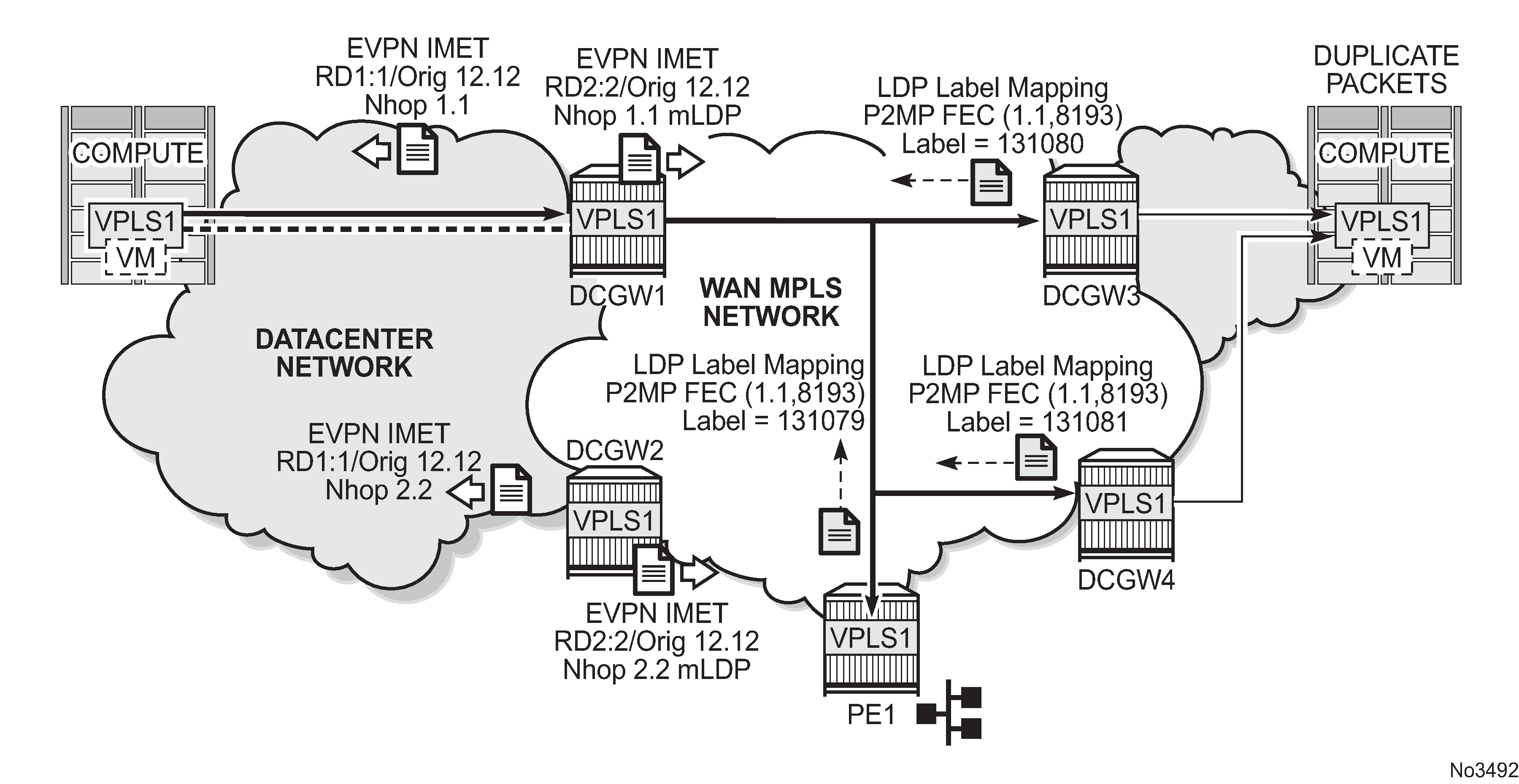
When mLDP is used with multiple anycast multihoming DCGWs, the same originating IP address must be used by all the DCGWs. Failure to do so may result in packet duplication.
In the example shown in Anycast multihoming and mLDP, each pair of DCGWs (DCGW1/DCGW2 and DCGW3/DCGW4) is configured with a different originating IP address, which causes the following behavior:
-
DCGW3 and DCGW4 receive the inclusive multicast routes with the same route key from DCGW1 and DCGW2.
-
Both DCGWs (DCGW3 and DCGW4) select only one route, which is generally the same, for example, DCGW1's inclusive multicast route.
-
As a result, DCGW3 and DCGW4 join the mLDP tree with root in DCGW1, creating packet duplication when DCGW1 sends BUM traffic.
-
Remote PE nodes with a single BGP-EVPN instance join the mLDP tree without any problem.
To avoid the packet duplication shown in Anycast multihoming and mLDP, Nokia recommends to configure the same originating IP address in all four DCGWs (DCGW1/DCGW2 and DCGW3/DCGW4). However, the route distinguishers can be different per pair.
The following behavior occurs if the same originating IP address is configured on the DCGW pairs shown in Anycast multihoming and mLDP.
-
DCGW3 and DCGW4 do not join any mLDP tree sourced from DCGW1 or DCGW2, which prevents any packet duplication. This is because a router ignore inclusive multicast routes received with its own originating-ip, regardless of the route-distinguisher.
-
PE1 joins the mLDP trees from the two DCs.
I-ES solution for dual BGP instance services
SR OS supports Interconnect ESs (I-ES) for VXLAN as per RFC9014. An I-ES is a virtual ES that allows DCGWs with two BGP instances to handle VXLAN access networks as any other type of ES. I-ESs support the RFC 7432 multihoming functions, including single-active and all-active, ESI-based split-horizon filtering, DF election, and aliasing and backup on remote EVPN-MPLS PEs.
In addition to the EVPN multihoming features, the main advantages of the I-ES redundant solution compared to the redundant solution described in Anycast redundant solution for dual BGP-instance services are as follows:
-
The use of I-ES for redundancy in dual BGP-instance services allows local SAPs on the DCGWs.
-
P2MP mLDP can be used to transport BUM traffic between DCs that use I-ES without any risk of packet duplication. As described in Using P2MP mLDP in redundant anycast DCGWs, packet duplication may occur in the anycast DCGW solution when mLDP is used in the WAN.
Where EVPN-MPLS networks are interconnected to EVPN-VXLAN networks, the I-ES concept applies only to the access VXLAN network; the EVPN-MPLS network does not modify its existing behavior.
The Interconnect ES concept shows the use of I-ES for Layer 2 EVPN DCI between VXLAN and MPLS networks.
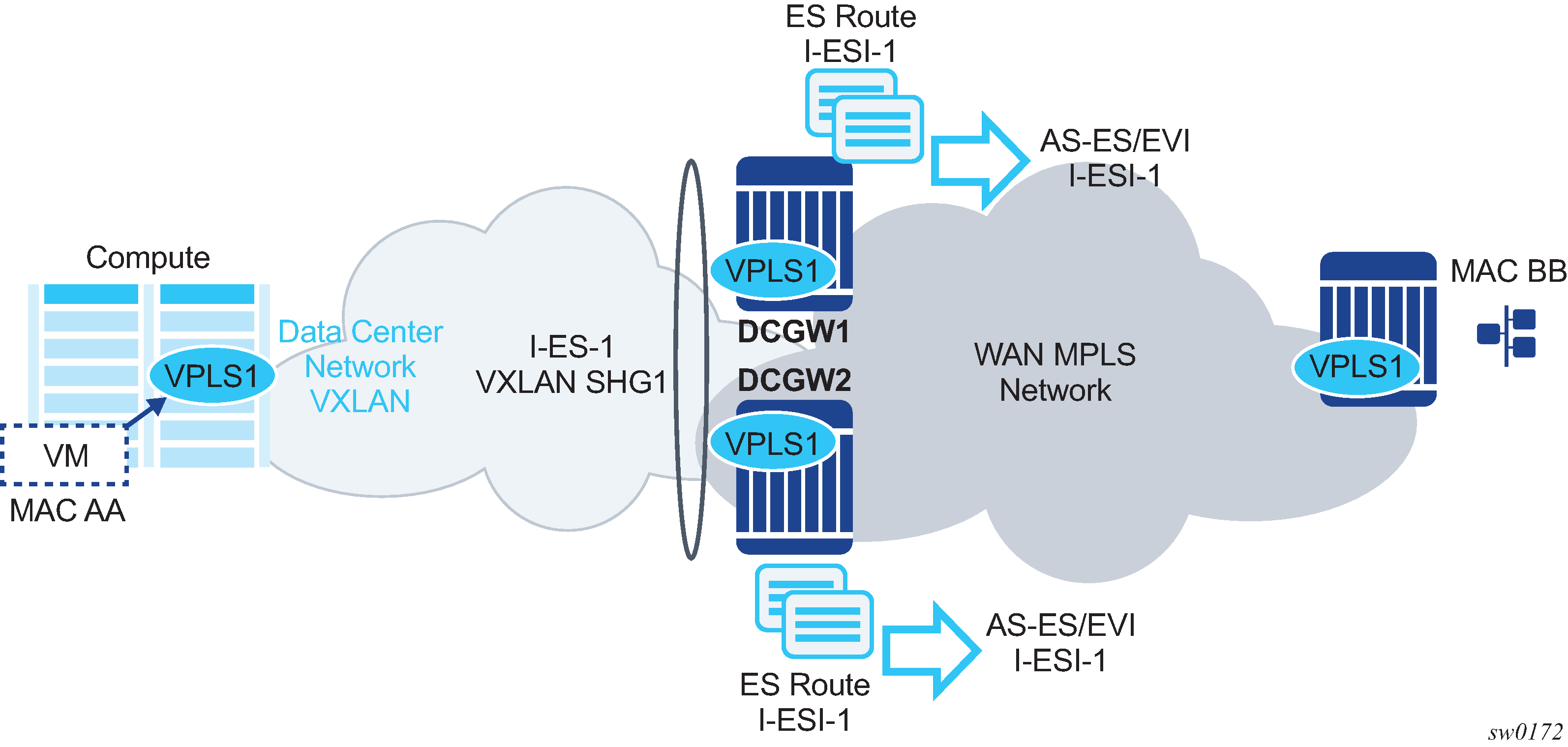
The following example shows how I-ES-1 would be provisioned on DCGW1 and the association between I-ES to a specified VPLS service. A similar configuration would occur on DCGW2 in the I-ES.
New I-ES configuration:
DCGW1#config>service>system>bgp-evpn#
ethernet-segment I-ES-1 virtual create
 esi 01:00:00:00:12:12:12:12:12:00
 service-carving
  mode auto
 multi-homing all-active
 network-interconnect-vxlan 1
 service-id
   service-range 1 to 1000
 no shutdown
Service configuration:
DCGW1#config>service>vpls(1)#
 vxlan instance 1 vni 1 instance 1 create
 exit
bgp
 route-distinguisher 1:1
bgp 2
 route-distinguisher 2:2
bgp-evpn
  evi 1
  vxlan bgp 1 vxlan-instance 1
   no shutdown
  exit
  mpls bgp 2
   auto-bind-tunnel resolution any
   no shutdown

...

DCGW1#config>service>vpls(2)#
 vxlan instance 1 vni 2 create
 exit
bgp
 route-distinguisher 3:3
bgp 2
 route-distinguisher 4:4
 bgp-evpn
  evi 2
  vxlan bgp 1 vxlan-instance 1
   no shutdown
  exit
  mpls bgp 2
   auto-bind-tunnel resolution any
   no shutdown
 sap 1/1/1:1 create
 exit
The above configuration associates I-ES-1 to the VXLAN instance in services VPLS1 and VPLS 2. The I-ES is modeled as a virtual ES, with the following considerations:
-
The commands network-interconnect-vxlan and service-id service-range svc-id [to svc-id] are required within the ES.
-
The network-interconnect-vxlan parameter identifies the VXLAN instance associated with the virtual ES. The value of the parameter must be set to 1. This command is rejected in a non-virtual ES.
-
The service-range parameter associates the specific service range to the ES. The ES must be configured as network-interconnect-vxlan before any service range can be added.
-
The ES parameters port, lag, sdp, vc-id-range, dot1q, and qinq cannot be configured in the ES when a network-interconnect-vxlan instance is configured. The source-bmac-lsb option is blocked, as the I-ES cannot be associated with an I-VPLS or PBB-Epipe service. The remaining ES configuration options are supported.
-
All services with two BGP instances associate the VXLAN destinations and ingress VXLAN instances to the ES.
-
-
Multiple services can be associated with the same ES, with the following considerations:
-
In a DC with two DCGWs (as in The Interconnect ES concept), only two I-ESs are needed to load-balance, where one half of the dual BGP-instance services would be associated with one I-ES (for example, I-ES-1, in the above configuration) and one half to another I-ES.
-
Up to eight service ranges per VXLAN instance can be configured. Ranges may overlap within the same ES, but not between different ESs.
-
The service range can be configured before the service.
-
-
After the I-ES is configured using network-interconnect-vxlan, the ES operational state depends exclusively on the ES administrative state. Because the I-ES is not associated with a physical port or SDP, when testing the non-revertive service carving manual mode, an ES shutdown and no shutdown event results in the node sending its own administrative preference and DP bit and taking control if the preference and DP bit are higher than the current DF. This is because the peer ES routes are not present at the EVPN application layer when the ES is configured for no shutdown; therefore, the PE sends its own administrative preference and DP values. For I-ESs, the non-revertive mode works only for node failures.
-
A VXLAN instance may be placed in MhStandby under any of the following situations:
-
if the PE is single-active NDF for that I-ES
-
if the VXLAN service is added to the I-ES and either the ES or BGP-EVPN MPLS is shut down in all the services included in the ES
The following example shows the change of the MhStandby flag from false to true when BGP-EVPN MPLS is shut down for all the services in the I-ES.
A:PE-4# show service id 500 vxlan instance 1 oper-flags
===============================================================================
VPLS VXLAN oper flags
===============================================================================
MhStandby                              : false
===============================================================================
A:PE-4# configure service vpls 500 bgp-evpn vxlan shutdown
*A:PE-4# show service id 500 vxlan instance 1 oper-flags
===============================================================================
VPLS VXLAN oper flags
===============================================================================
MhStandby                              : true
===============================================================================
-
BGP-EVPN routes on dual BGP-instance services with I-ES
The configuration of an I-ES on DCGWs with two BGP instances has the following impact on the advertisement and processing of BGP-EVPN routes.
-
For EVPN MAC/IP routes, the following considerations apply:
If bgp-evpn>vxlan>no auto-disc-route-advertisement and mh-mode access are configured on the access instance:
-
MAC/IP routes received in the EVPN-MPLS BGP instance are readvertised in the EVPN-VXLAN BGP instance with the ESI set to zero.
-
EVPN-VXLAN PEs and NVEs in the DC receive the same MAC from two or more different MAC/IP routes from the DCGWs, which perform regular EVPN MAC/IP route selection.
-
MAC/IP routes received in the EVPN-VXLAN BGP instance are readvertised in the EVPN-MPLS BGP instance with the configured non-zero I-ESI value, assuming the VXLAN instance is not in an MhStandby operational state; otherwise the MAC/IP routes are dropped.
-
EVPN-MPLS PEs in the WAN receive the same MAC from two or more DCGWs set with the same ESI. In this case, regular aliasing and backup functions occur as usual.
-
-
If bgp-evpn>vxlan>auto-disc-route-advertisement and mh-mode access are configured, the following differences apply to the above:
-
MAC/IP routes received in the EVPN-MPLS BGP instance are readvertised in the EVPN-VXLAN BGP instance with the ESI set to the I-ESI.
-
In this case, EVPN-VXLAN PEs and NVEs in the DC receive the same MAC from two or more different MAC/IP routes from the DCGWs, with the same ESI, therefore they can perform aliasing.
-
-
ES routes are exchanged for the I-ES. The routes should be sent only to the MPLS network and not to the VXLAN network. This can be achieved by using router policies.
-
AD per-ES and AD per-EVI routes are also advertised for the I-ES, and are sent only to the MPLS network and not to the VXLAN if bgp-evpn>vxlan>no auto-disc-route-advertisement is configured. For ES routes, router polices can be used to prevent these routes from being sent to VXLAN peers. If bgp-evpn>vxlan>auto-disc-route-advertisement is configured, AD routes must be sent to the VXLAN peers so that they can apply backup or aliasing functions.
In general, when I-ESs are used for redundancy, the use of router policies is needed to avoid control plane loops with MAC/IP routes. Consider the following to avoid control plane loops:
-
loops created by remote MACs
Remote EVPN-MPLS MAC/IP routes are readvertised into EVPN-VXLAN routes with an SOO (Site Of Origin) EC added by a BGP peer or VSI export policy identifying the DCGW pair. The other DCGW in the pair drops EVPN-VXLAN MAC/IP routes tagged with the pair SOO. Router policies are needed to add SOO and drop routes received with self SOO.
When remote EVPN-VXLAN MAC/IP routes are readvertised into EVPN-MPLS, the DCGWs automatically drop EVPN-MPLS MAC/IP routes received with their own non-zero I-ESI.
-
loops created by local SAP MACs
Local SAP MACs are learned and MAC/IP routes are advertised into both BGP instances. The MAC/IP routes advertised in the EVPN-VXLAN instance are dropped by the peer based on the SOO router policies as described above for loops created by remote MACs. The DCGW local MACs are always learned over the EVPN-MPLS destinations between the DCGWs.
The following describes the considerations for BGP peer policies on DCGW1 to avoid control plane loops. Similar policies would be configured on DCGW2.
-
Avoid sending service VXLAN routes to MPLS peers and service MPLS routes to VXLAN peers.
-
Avoid sending AD and ES routes to VXLAN peers. If bgp-evpn>vxlan>auto-disc-route-advertisement is configured AD routes must be sent to the VXLAN peers.
-
Add SOO to VXLAN routes sent to the ES peer.
-
Drop VXLAN routes received from the ES peer.
The following shows the CLI configuration:
A:DCGW1# configure router bgp
A:DCGW1>config>router>bgp# info
----------------------------------------------
            family vpn-ipv4 evpn
            vpn-apply-import
            vpn-apply-export
            rapid-withdrawal
            rapid-update vpn-ipv4 evpn
            group "wan"
                type internal
                export "allow only mpls"
                neighbor 192.0.2.4
                exit
                neighbor 192.0.2.5
                exit
            exit
            group "internal"
                type internal
                neighbor 192.0.2.1
                    export "allow only vxlan"
                exit
                neighbor 192.0.2.3
                    import "drop SOO-DCGW-23"
                    export "add SOO to vxlan routes"
                exit
            exit
            no shutdown
----------------------------------------------
A:DCGW1>config>router>bgp# /configure router policy-options
A:DCGW1>config>router>policy-options# info
----------------------------------------------
            community "mpls" members "bgp-tunnel-encap:MPLS"
            community "vxlan" members "bgp-tunnel-encap:VXLAN"
            community "SOO-DCGW-23" members "origin:64500:23"
// This policy prevents the router from sending service VXLAN routes to MPLS peers. //
  policy-statement "allow only mpls"
                entry 10
                    from
                        community "vxlan"
                        family evpn
                    exit
                    action drop
                    exit
                exit
            exit
This policy ensures the router only exports routes that include the VXLAN encapsulation.
   policy-statement "allow only vxlan"
                entry 10
                    from
                        community "vxlan"
                        family evpn
                    exit
                    action accept
                    exit
                exit
                default-action drop
                exit
            exit
This import policy avoids importing routes with a self SOO.
  policy-statement "drop SOO-DCGW-23"
                entry 10
                    from
                        community "SOO-DCGW-23"
                        family evpn
                    exit
                    action drop
                    exit
                exit
            exit
This import policy adds SOO only to VXLAN routes. This allows the peer to drop routes based on the SOO, without affecting the MPLS routes.
  policy-statement "add SOO to vxlan routes"
                entry 10
                    from
                        community "vxlan"
                        family evpn
                    exit
                    action accept
                        community add "SOO-DCGW-23"
                    exit
                exit
                default-action accept
                exit
            exit
----------------------------------------------
Single-active multihoming on I-ES
When an I-ES is configured as single-active and configured as no shutdown with at least one associated service, the DCGWs send ES and AD routes as for any ES. It also runs DF election as normal, based on the ES routes, with the candidate list being pruned by the AD routes.
I-ES — single-active shows the expected behavior for a single-active I-ES.
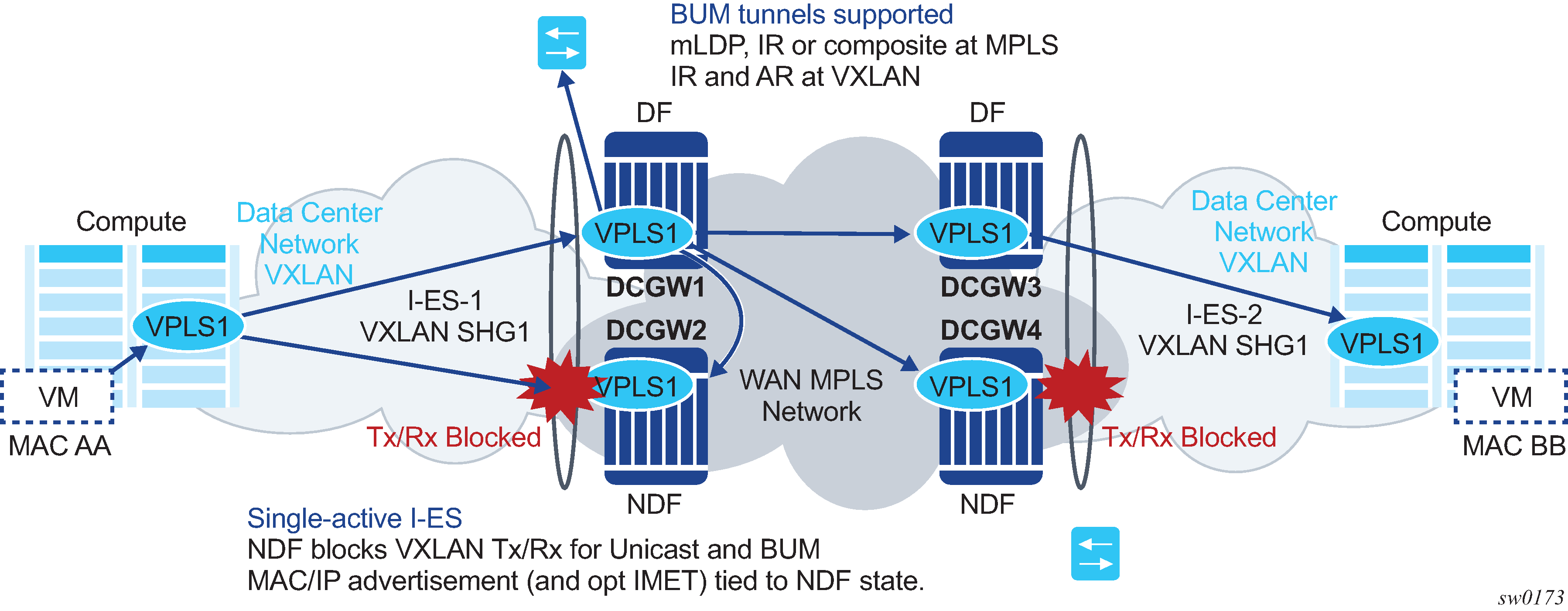
As shown in I-ES — single-active, the Non-Designated Forwarder (NDF) for a specified service carries out the following tasks:
-
From a datapath perspective, the VXLAN instance on the NDF goes into an MhStandby operational state and blocks ingress and egress traffic on the VXLAN destinations associated with the I-ES.
-
The MAC/IP routes and the FDB process
-
MAC/IP routes associated with the VXLAN instance and readvertised to EVPN-MPLS peers are withdrawn.
-
MAC/IP routes corresponding to local SAP MACs or EVPN-MPLS binding MACs are withdrawn if they were advertised to the EVPN-VXLAN instance.
-
Received MAC/IP routes associated with the VXLAN instance are not installed in the FDB. MAC/IP routes show as ‟used” in BGP; however, only the MAC/IP route received from MPLS (from the ES peer) is programmed.
-
-
The Inclusive Multicast Ethernet Tag (IMET) routes process
-
IMET-AR-R routes (IMET-AR with replicator role) must be withdrawn if the VXLAN instance goes into an MhStandby operational state. Only the DF advertises the IMET-AR-R routes.
-
IMET-IR advertisements in the case of the NDF (or MhStandby) are controlled by the command config>service>vpls>bgp-evpn>vxlan [no] send-imet-ir-on-ndf.
By default, the command is enabled and the router advertises IMET-IR routes, even if the PE is NDF (MhStandby). This attracts BUM traffic, but also speeds up convergence in the case of a DF switchover. The command is supported for single-active and all-active.
If the command is disabled, the router withdraws the IMET-IR routes when the PE is NDF and do not attract BUM traffic.
-
The I-ES DF PE for the service continues advertising IMET and MAC/IP routes for the associated VXLAN instance as usual, as well as forwarding on the DF VXLAN bindings. When the DF DCGW receives BUM traffic, it sends the traffic with the egress ESI label if needed.
All-active multihoming on I-ES
The same considerations for ES and AD routes, and DF election apply for all-active multihoming as for single-active multihoming; the difference is in the behavior on the NDF DCGW. The NDF for a specified service performs the following tasks:
-
From a datapath perspective, the NDF blocks ingress and egress paths for broadcast and multicast traffic on the VXLAN instance bindings associated with the I-ES, while unknown and known unicast traffic is still allowed. The unknown unicast traffic is transmitted on the NDF if there is no risk of duplication. For example, unknown unicast packets are transmitted on the NDF if they do not have an ESI label, do not have an EVPN BUM label, and they pass a MAC SA suppression. In the example in All-active multihoming and unknown unicast on the NDF, the NDF transmits unknown unicast traffic. Regardless of whether DCGW1 is a DF or NDF, it accepts the unknown unicast packets and floods to local SAPs and EVPN destinations. When sending to DGW2, the router sends the ESI label identifying the I-ES. Because of the ESI-label suppression, DCGW2 does not send unknown traffic back to the DC.
Figure 42. All-active multihoming and unknown unicast on the NDF 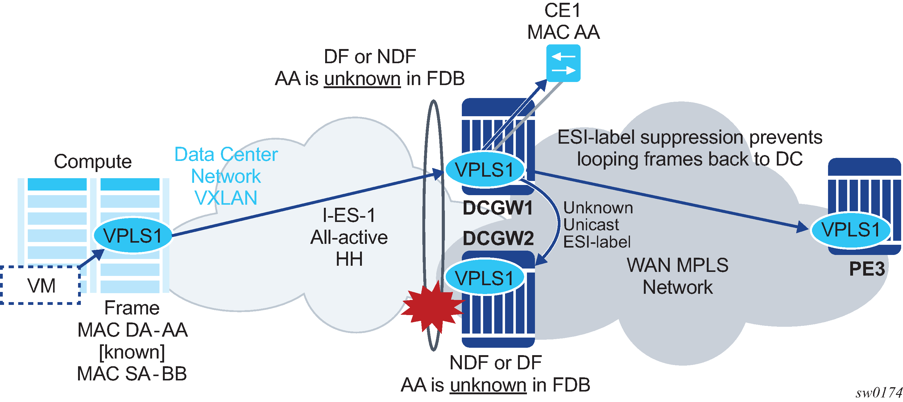
-
The MAC/IP routes and the FDB process
-
MAC/IP routes associated with the VXLAN instance are advertised normally.
-
MACs are installed as normal in the FDB for received MAC/IP routes associated with the VXLAN instance.
-
-
The IMET routes process
-
As with single-active multihoming, IMET-AR-R routes must be withdrawn on the NDF (MhStandby state). Only the DF advertises the IMET-AR-R routes.
-
The IMET-IR advertisements in the case of the NDF (or MhStandby) are controlled by the command config>service>vpls>bgp-evpn>vxlan [no] send-imet-ir-on-ndf, as in single-active multihoming.
-
The behavior on the non-DF for BUM traffic can also be controlled by the command config>service>vpls>vxlan>rx-discard-on-ndf {bm | bum | none}, where the default option is bm. However, the user can change this option to discard all BUM traffic, or forward all BUM traffic (none).
The I-ES DF PE for the service continues advertising IMET and MAC/IP routes for the associated VXLAN instance as usual. When the DF DCGW receives BUM traffic, it sends the traffic with the egress ESI label if needed.
Multi-instance EVPN: Two instances of the same encapsulation in the same VPLS/R-VPLS service
For example, a VPLS service can be configured with two VXLAN instances that use VNI 500 and 501 respectively, and those instances can be associated with different BGP instances:
*A:PE-2# configure service vpls 500
*A:PE-2>config>service>vpls# info
----------------------------------------------
vxlan instance 1 vni 500 create
exit
vxlan instance 2 vni 501 create
exit
bgp
 route-distinguisher 192.0.2.2:500
 vsi-export "vsi-500-export"
 vsi-import "vsi-500-import"
exit
bgp 2
 route-distinguisher 192.0.2.2:501
 vsi-export "vsi-501-export"
 vsi-import "vsi-501-import"
exit
bgp-evpn
 incl-mcast-orig-ip 23.23.23.23
 evi 500
 vxlan bgp 1 vxlan-instance 1
 no shutdown
 exit
 vxlan bgp 2 vxlan-instance 2
 no shutdown
 exit
exit
stp
shutdown
exit
no shutdown
----------------------------------------------
From a data plane perspective, each VXLAN instance is instantiated in a different implicit SHG, so that traffic can be forwarded between them.
In addition, multi-instance EVPN-VXLAN services support:
-
assisted-replication for IPv4 VTEPs in both VXLAN instances, where a single assisted-replication IPv4 address can be used for both instances
-
non-system IP and IPv6 termination, where a single vxlan-src-vtep ip-address can be configured for each service, and therefore used for the two instances
*A:PE-2# configure service vpls 700
*A:PE-2>config>service>vpls# info
----------------------------------------------
description "two bgp-evpn mpls instances"
bgp
  route-distinguisher auto-rd
  vsi-export "vsi-700-export"
  vsi-import "vsi-700-import"
exit
bgp 2
  route-distinguisher auto-rd
  vsi-export "vsi-701-export"
  vsi-import "vsi-701-import"
exit
bgp-evpn
  evi 700
  mpls bgp 1
    mh-mode access
    ingress-replication-bum-label
    auto-bind-tunnel
      resolution any
    exit
    no shutdown
  exit
  mpls bgp 2
    mh-mode network
    ingress-replication-bum-label
    auto-bind-tunnel
      resolution any
    exit
    no shutdown
  exit
exit
stp
  shutdown
exit
no shutdown
----------------------------------------------
Multi-instance EVPN-MPLS VPLS/R-VPLS services have the same limitations as any multi-instance service, as described in Multi-instance EVPN: Two instances of the same encapsulation in the same VPLS/R-VPLS service. In addition, services with two EVPN-MPLS instances do not support SAPs.
The mh-mode {network|access} command in the vpls>bgp-evpn>mpls context determines which instance is considered access and which instance is considered network.
- The default form of the bgp-evpn>mpls command is mh-mode network and only one instance can be configured. The other instance must be configured as mh-mode access.
- The use of provider-tunnel is supported if there is one instance configured as network, and the P2MP tunnel is implicitly associated with the network instance.
Multi-instance EVPN-MPLS VPLS/R-VPLS services support:
-
all of the auto-bind-tunnel resolution options in each of the two instances. This includes resolution of IPv4 next-hops to TTMv4 entries and resolution of IPv6 next-hops to TTMv6 entries.
-
different address families in different instances. For instance, mpls bgp 1 may resolve routes to TTMv4 and mpls bgp 2 to TTMv6, or the reverse. In a VPLS service with two EVPN-VXLAN instances, it is not possible to have an instance with routes resolved to IPv4 VXLAN tunnels and the other instance with routes resolved to IPv6 VXLAN tunnels.
-
an explicit split-horizon-group in each instance; however, the same split-horizon-group cannot be configured on the two instances of the same VPLS service
-
a restrict-protected-src discard-frame per instance. If a MAC is protected in one instance and a frame arrives at the other instance with the protected MAC as source MAC, the frame is discarded if restrict-protected-src discard-frame is configured.
BGP-EVPN routes in multi-instance EVPN services with the same encapsulation
If two BGP instances with the same encapsulation (VXLAN or MPLS) are configured in the same VPLS/R-VPLS service, different import route targets in each BGP instance are mandatory (although this is not enforced).
BGP-EVPN routes in services configured with two BGP instances describes the use of policies to avoid sending WAN routes (routes meant to be redistributed from DC to WAN) to the DC again and DC routes (routes meant to be redistributed from WAN to DC) to the WAN again. Those policies are based on export policy statements that match on the RFC 9012 BGP encapsulation extended community (MPLS and VXLAN respectively).
When the two BGP instances are of the same encapsulation (VXLAN or MPLS), the policies matching on different BGP encapsulation extended community are not feasible because both instances advertise routes with the same encapsulation value. Because the export route targets in the two BGP instances must be different, the policies, to avoid sending WAN routes back to the WAN and DC routes back to the DC, can be based on export policies that prevent routes with a DC route target from being sent to the WAN peers (and opposite for routes with a WAN route target).
In scaled scenarios, matching based on route targets, does not scale well. An alternative and preferred solution is to configure a default-route-tag that identifies all the EVPN instances connected to the DC (or one domain), and a different default-route-tag in all the EVPN instances connected to the WAN (or the other domain). Anycast redundant solution for multi-instance EVPN services with the same encapsulation shows an example that demonstrates the use of default-route-tags.
Other than the specifications described in this section, the processing of MAC/IP routes and inclusive multicast Ethernet tag routes in multi-instance EVPN services of the same encapsulation follow the rules described in BGP-EVPN routes in services configured with two BGP instances.
Anycast redundant solution for multi-instance EVPN services with the same encapsulation
The solution described in Anycast redundant solution for dual BGP-instance services is also supported in multi-instance EVPN VPLS/R-VPLS services with the same encapsulation.
The following CLI example output shows the configuration of DCGW-1 and DCGW-2 in Multihomed anycast solution where VPLS 500 is a multi-instance EVPN-VXLAN service and BGP instance 2 is associated with VXLAN instead of MPLS.
Different default-route-tags are used in BGP instance 1 and instance 2, so that in the export route policies, DC routes are not advertised to the WAN, and WAN routes are not advertised to the DC, respectively.
*A:DCGW-1(and DCGW-2)>config>service>vpls(500)# info
----------------------------------------------
vxlan instance 1 vni 500 create
exit
vxlan instance 2 vni 501 create
exit
bgp
 route-distinguisher 192.0.2.2:500
 route-target target:64500:500
exit
bgp 2
 route-distinguisher 192.0.2.2:501
 route-target target:64500:501
exit
bgp-evpn
 incl-mcast-orig-ip 23.23.23.23
 evi 500
 vxlan bgp 1 vxlan-instance 1
 default-route-tag 500
 no shutdown
 exit
 vxlan bgp 2 vxlan-instance 2
   default-route-tag 501
   no shutdown
 exit
exit
stp
shutdown
exit
no shutdown
----------------------------------------------
config>router>bgp#
 vpn-apply-import
 vpn-apply-export
 group "WAN"
  family evpn
  type internal
  export "allow only mpls"
  neighbor 192.0.2.6
 group "DC"
  family evpn
  type internal
export "allow only vxlan"
  neighbor 192.0.2.2

config>router>policy-options# info
----------------------------------------------
            policy-statement "allow only mpls"
                entry 10
                  from
                    family evpn
                    tag 500
                  action drop
                  exit
                exit
            exit
            policy-statement "allow only vxlan"
                entry 10
                  from
                    family evpn
                    tag 501
                  action drop
       exit
                  exit
            exit
The same Anycast redundant solution can be applied to VPLS/R-VPLS with two instances of EVPN-MPLS encapsulation. The configuration would be identical, other than replacing the VXLAN aspects with the EVPN-MPLS-specific parameters.
For a full description of this solution, see the Anycast redundant solution for dual BGP-instance services
I-ES solution for dual BGP EVPN instance services with the same encapsulation
The I-ES of network-interconnect VXLAN Ethernet segment is described in I-ES solution for dual BGP instance services. I-ES’s are also supported on VPLS and R-VPLS services with two EVPN-VXLAN instances.
I-ES in dual EVPN-VXLAN services shows the use of an I-ES in a dual EVPN-VXLAN instance service.
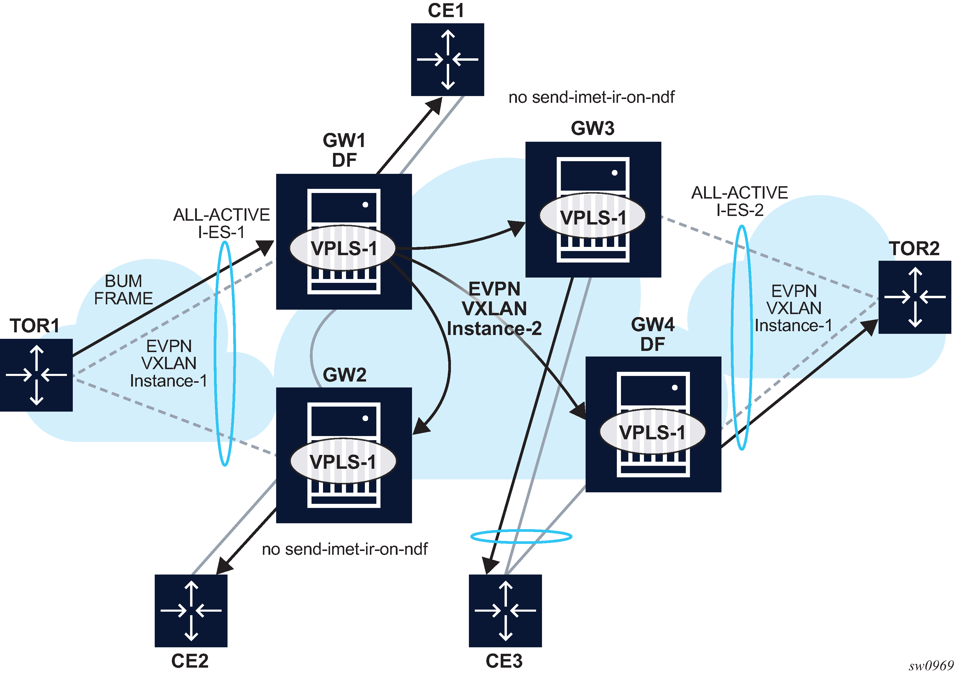
Similar to (single-instance) EVPN-VXLAN all-active multihoming, the BUM forwarding procedures follow the ‟Local Bias” behavior.
At the ingress PE, the forwarding rules for EVPN-VXLAN services are as follows:
-
The no send-imet-ir-on-ndf or rx-discard-on-ndf bum command must be enabled so that the NDF does not forward any BUM traffic.
-
BUM frames received on any SAP or I-ES VXLAN binding are flooded to:
-
local non-ES and single-active DF ES SAPs
-
local all-active ES SAPs (DF and NDF)
-
EVPN-VXLAN destinations
BUM received on an I-ES VXLAN binding follows SHG rules, for example, it can only be forwarded to EVPN-VXLAN destinations that belong to the other VXLAN instance (instance 2), which is a different SHG.
-
-
As an example, in I-ES in dual EVPN-VXLAN services:
-
GW1 and GW2 are configured with no send-imet-ir-on-ndf.
-
TOR1 generates BUM traffic that only reaches GW1 (DF).
-
GW1 forwards to CE1 and EVPN-VXLAN destinations.
-
The forwarding rules at the egress PE are as follows:
-
The source VTEP is looked up for BUM frames received on EVPN-VXLAN.
-
If the source VTEP matches one of the PEs with which the local PE shares an ES _AND_ a VXLAN service:
-
Then the local PE does not forward to the shared local ESs (this includes port, lag, or network-interconnect-vxlan ESs). It forwards though to non-shared ES SAPs unless they are in NDF state.
-
Else, the local PE forwards normally to local ESs unless they are in NDF state.
-
-
Because there is no multicast label or multicast B-MAC in VXLAN, the only way the egress PE can identify BUM traffic is by looking at the customer MAC DA. Therefore, BM or unknown MAC DAs identify BUM traffic.
-
As an example, in I-ES in dual EVPN-VXLAN services:
-
GW2 receives BUM on EVPN-VXLAN. GW2 identifies the source VTEP as a PE with which the I-ES-1 is shared, therefore it does not forward the BUM frames to the local I-ES. It forwards to the non-shared ES and local SAPs though (CE2).
-
GW3 receives BUM on EVPN-VXLAN, however the source VTEP does not match any PE with which GW3 shares an ES. Hence GW3 forwards to all local ESs that are DF, in other words, CE3.
-
The following configuration example shows how I-ES-1 would be provisioned on DCGW1 and the association between I-ES to a specified VPLS service. A similar configuration would occur on DCGW2 in the I-ES.
I-ES configuration:
*A:GW1>config>service>system>bgp-evpn>eth-seg# info
----------------------------------------------
                esi 00:23:23:23:23:23:23:00:00:01
                service-carving
                    mode manual
                    manual
                        preference non-revertive create
                            value 150
                        exit
                        evi 101 to 200
                    exit
                exit
                multi-homing all-active
                network-interconnect-vxlan 1
                service-id
                    service-range 1
                    service-range 1000 to 1002
                    service-range 2000
                exit
                no shutdown
Service configuration:
*A:GW1>config>service>vpls# info
----------------------------------------------
            vxlan instance 1 vni 1000 create
                rx-discard-on-ndf bum
            exit
            vxlan instance 2 vni 1002 create
            exit
            bgp
                route-target export target:64500:1000 import target:64500:1000
            exit
            bgp 2
                route-distinguisher auto-rd
                route-target export target:64500:1002 import target:64500:1002
            exit
            bgp-evpn
                evi 1000
                vxlan bgp 1 vxlan-instance 1
                    ecmp 2
                    default-route-tag 100
                    auto-disc-route-advertisement
                    no shutdown
                exit
                vxlan bgp 2 vxlan-instance 2
                    ecmp 2
                    default-route-tag 200
                    auto-disc-route-advertisement
                    mh-mode network
                    no shutdown
                exit
            exit
            no shutdown
Multi-instance EVPN VPLS/R-VPLS services with two EVPN-MPLS instances do not support I-ESs.
For information about how the EVPN routes are processed and advertised in an I-ES, see the I-ES solution for dual BGP instance services.
EVPN IP-VRF-to-IP-VRF models
SR OS supports the three IP-VRF-to-IP-VRF models defined in RFC 9136 for EVPN services. Those three models are known as:
-
interface-ful IP-VRF-to-IP-VRF with Supplementary Bridge Domain Integrated Routing Bridging (SBD IRB)
-
interface-ful IP-VRF-to-IP-VRF with unnumbered SBD IRB
-
interface-less IP-VRF-to-IP-VRF
The three models refer to different control and data plane procedures to advertise and process the EVPN IP-Prefix routes. The interface-less model also supports the advertisement and processing of host routes by using EVPN MAC/IP Advertisement routes (instead of IP-Prefix routes), as specified in the symmetric IRB model in RFC 9135.
SR OS supports the preceding models for IPv4 and IPv6 prefixes. Vendors may choose different models depending on the use cases that they intend to address. When a third-party vendor is connected to an SR OS router, it is important to know which of the three models the third-party vendor implements.
Interface-ful IP-VRF-to-IP-VRF with SBD IRB model
The SBD is equivalent to an R-VPLS that connects all the PEs that are attached to the same tenant VPRN. Interface-ful refers to the use of a full IRB interface between the VPRN and the SBD (an interface object with MAC and IP addresses, over which interface parameters can be configured).
The following figure shows an example of the interface-ful IP-VRF-to-IP-VRF with SBD IRB model.
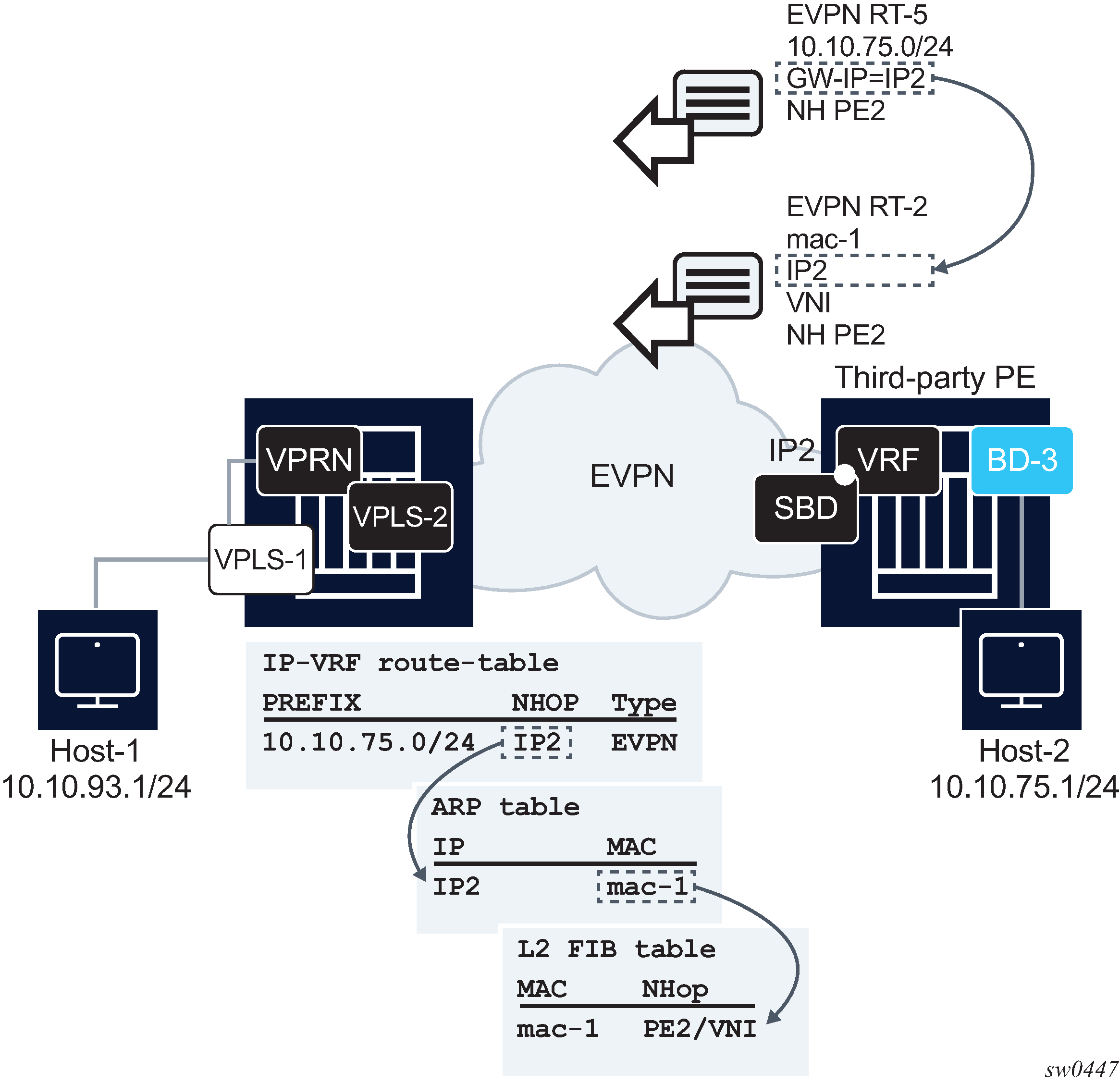
In the preceding figure, an SR OS router and a third-party router are using the interface-ful IP-VRF-to-IP-VRF with SBD IRB model. The two routers are attached to a VPRN for the same tenant, and those VPRNs are connected by R-VPLS-2, or SBD. Both routers exchange IP prefix routes with a non-zero gateway IP, which is the IP address of the SBD IRB. The SBD IRB MAC and IP are advertised in a MAC/IP route. On reception, the IP prefix route creates a route-table entry in the VPRN, where the gateway IP must be recursively resolved to the information provided by the MAC/IP route and installed in the ARP and FDB tables.
This model is detailed in EVPN for VXLAN in IRB backhaul R-VPLS services and IP prefixes. The following is an example of the configuration of SBD and VPRN, as shown in Interface-ful IP-VRF-to-IP-VRF with SBD IRB model.
A:node-2>config>service

vpls 2 customer 1 name "sbd" create
 allow-ip-int-bind
 exit
 bgp
 exit
 bgp-evpn
 evi 2
 ip-route-advertisement
 mpls bgp 1
 auto-bind-tunnel resolution any
 no shutdown

vprn 1 customer 1 name "vprn1" create
 route-distinguisher auto-rd
 interface "sbd" create
 address 192.168.0.1/16
 ipv6
   30::3/64
 exit
 vpls "sbd"
The interface-ful IP-VRF-to-IP-VRF with SBD IRB model is also supported for IPv6 prefixes. There are no configuration differences except the ability to configure an IPv6 address and interface.
Interface-ful IP-VRF-to-IP-VRF with unnumbered SBD IRB model
Interface-ful refers to the use of a full IRB interface between the VPRN and the SBD. However, the SBD IRB is unnumbered in this model, which means no IP address is configured on it. In SR OS, an unnumbered SBD IRB is equivalent to an R-VPLS that is linked to a VPRN interface through an EVPN tunnel. See EVPN for VXLAN in EVPN tunnel R-VPLS services for more information.
The following figure shows an example of the interface-ful IP-VRF-to-IP-VRF with unnumbered SBD IRB model.
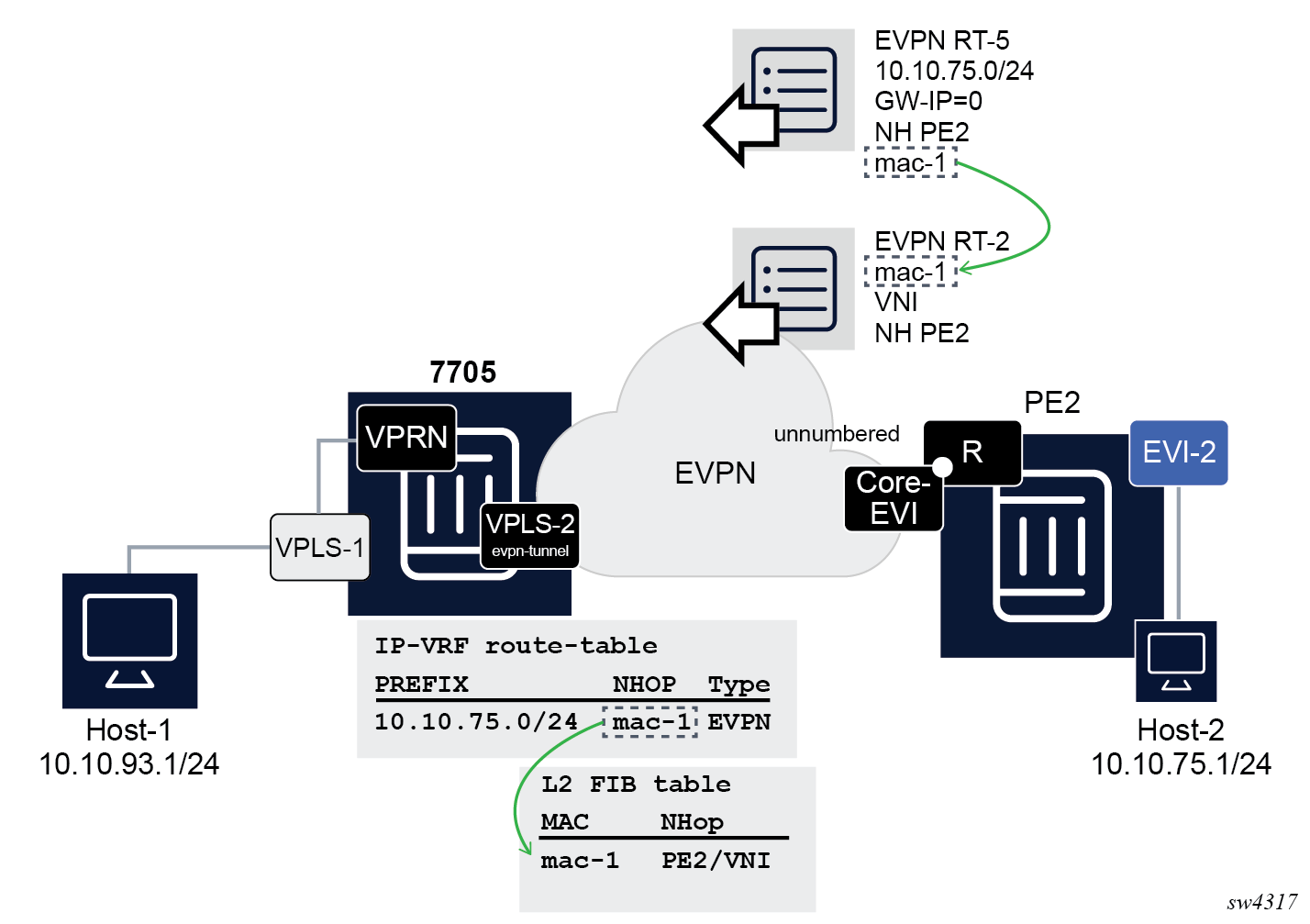
In the preceding figure, an SR OS router and a third-party router are using the interface-ful IP-VRF-to-IP-VRF with unnumbered SBD IRB model. The IP prefix routes are expected to have a zero gateway IP, and the MAC in the router's MAC extended community is used for the recursive resolution to a MAC/IP route.
The corresponding configuration of the VPRN and SBD in the example could be:
A:node-2>config>service

vpls 2 customer 1 name "sbd" create
 allow-ip-int-bind
 exit
 bgp
 exit
 bgp-evpn
evi 2
ip-route-advertisement
mpls bgp 1
auto-bind-tunnel resolution any
no shutdown

vprn 1 customer 1 create
 route-distinguisher auto-rd
 interface "sbd" create
  ipv6
  exit
 vpls "sbd"
  evpn-tunnel ipv6-gateway-address mac
The evpn-tunnel command controls the use of the router's MAC extended community and the zero gateway IP in the IPv4-prefix route. For IPv6, the ipv6-gateway-address mac command allows the router to advertise the IPv6-prefix routes with a router's MAC extended community and zero gateway IP.
Interoperable interface-less IP-VRF-to-IP-VRF model (Ethernet encapsulation)
The interface-less model does not require a Supplementary Broadcast Domain (SBD) connecting the VPRNs for the tenant, and no recursive resolution is required upon receiving an IP prefix route. In other words, the next-hop of the IP prefix route is directly resolved to an EVPN tunnel without the need for any other route. The standard specification RFC 9136 supports two variants of this model that are not interoperable.
-
EVPN IFL for Ethernet Network Virtualization Overlay (NVO) tunnels
Ethernet NVO indicates that the EVPN packets contain an inner Ethernet header. This is the case for tunnels such as VXLAN
In the Ethernet NVO option, the ingress PE uses the received router’s MAC extended community address (received along with the route type 5) as the inner destination MAC address for the EVPN packets sent to the prefix.
-
EVPN IFL for IP NVO tunnels
IP NVO indicates that the EVPN packets contain an inner IP packet, but without Ethernet header. This is similar to the IPVPN packets exchanged between PEs.
The following figure shows an example of the interface-less IP-VRF-to-IP-VRF model.
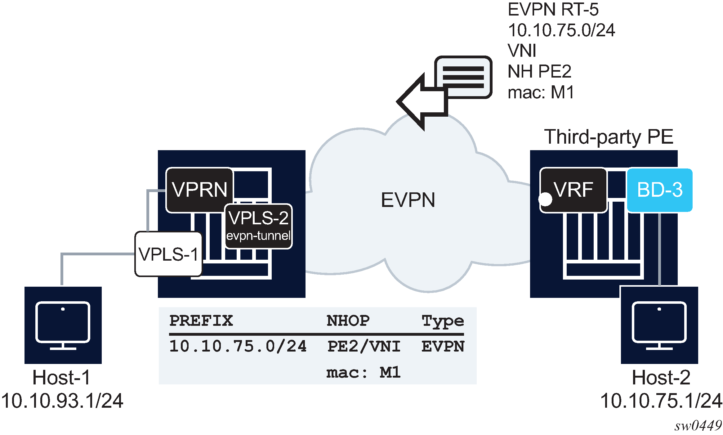
SR OS supports the interoperable Interface-less IP-VRF-to-IP-VRF Model for Ethernet NVO tunnels. In the preceding figure, this interoperable is shown on the left-most PE router. The following is the model implementation.
-
There is no datapath difference between this model and the existing R-VPLS EVPN tunnel model or the model described in Interface-ful IP-VRF-to-IP-VRF with unnumbered SBD IRB model.
-
This model is enabled by configuring the config service vprn if vpls evpn-tunnel (with ipv6-gateway-address mac for IPv6) and bgp-evpn ip-route-advertisement commands. In addition, because the SBD IRB MAC/IP route is no longer needed, the config service vpls bgp-evpn no mac-advertisement command prevents the advertisement of the MAC/IP route.
-
The following IP prefix routes are processed as follows.
-
On transmission, there is no change in the IP prefix route processing compared to the configuration of the Interface-ful IP-VRF-to-IP-VRF with unnumbered SBD IRB model.
-
IPv4 or IPv6 prefix routes are advertised, based on the information in the route-table for IPv4 and IPv6, with GW-IP=0 and the corresponding MAC extended community.
-
If the bgp-evpn no mac-advertisement command is configured, no MAC/IP route is sent for the R-VPLS.
-
-
The received IPv4 or IPv6 prefix routes are processed as follows.
-
Upon receiving an IPv4 or IPv6 prefix route with a MAC extended community for the router, an internal MAC/IP route is generated with the encoded MAC and the RD, Ethernet tag, ESI, Label/VNI and next hop from the IP prefix route itself.
-
If no competing received MAC/IP routes exists for the same MAC, this IP prefix-derived MAC/IP route is selected and the MAC installed in the R-VPLS FDB with type "Evpn".
-
After the MAC is installed in FDB, there are no differences between this interoperable interface-less model and the interface-ful with unnumbered SBD IRB model. Therefore SR OS is compatible with the received IP prefix routes for both models.
-
-
The following is an example of a typical configuration of a PE's SBD and VPRN that work in interface-less model for IPv4 and IPv6.
A:node-2>config>service

vpls 2 customer 1 name "sbd" create
       allow-ip-int-bind
       exit
       bgp
       exit
       bgp-evpn
            evi 2
            no mac-advertisement
            ip-route-advertisement
            mpls bgp 1
                 auto-bind-tunnel resolution any
                 no shutdown
vprn 1 customer 1 create
       route-distinguisher auto-rd
       interface "sbd" create
            ipv6
            exit
            vpls "sbd"
                 evpn-tunnel ipv6-gateway-address mac
Interface-less IP-VRF-to-IP-VRF model (IP encapsulation) for MPLS tunnels
In addition to the Interface-ful and interoperable Interface-less models described in Interface-ful IP-VRF-to-IP-VRF with SBD IRB model, Interface-ful IP-VRF-to-IP-VRF with unnumbered SBD IRB model, and Interoperable interface-less IP-VRF-to-IP-VRF model (Ethernet encapsulation) sections, SR OS also supports the Interface-less Model (EVPN IFL) with IP encapsulation for MPLS tunnels. The RFC 9136 standard specification refers to this model as the EVPN IFL model for IP NVO tunnels.
Compared to the Ethernet NVO model in which the ingress PE pushes an inner Ethernet header, the IP packet in this EVPN IFL model is directly encapsulated with an EVPN service label and the transport labels.
The following figure shows the EVPN IFL model with IP encapsulation for MPLS tunnels.
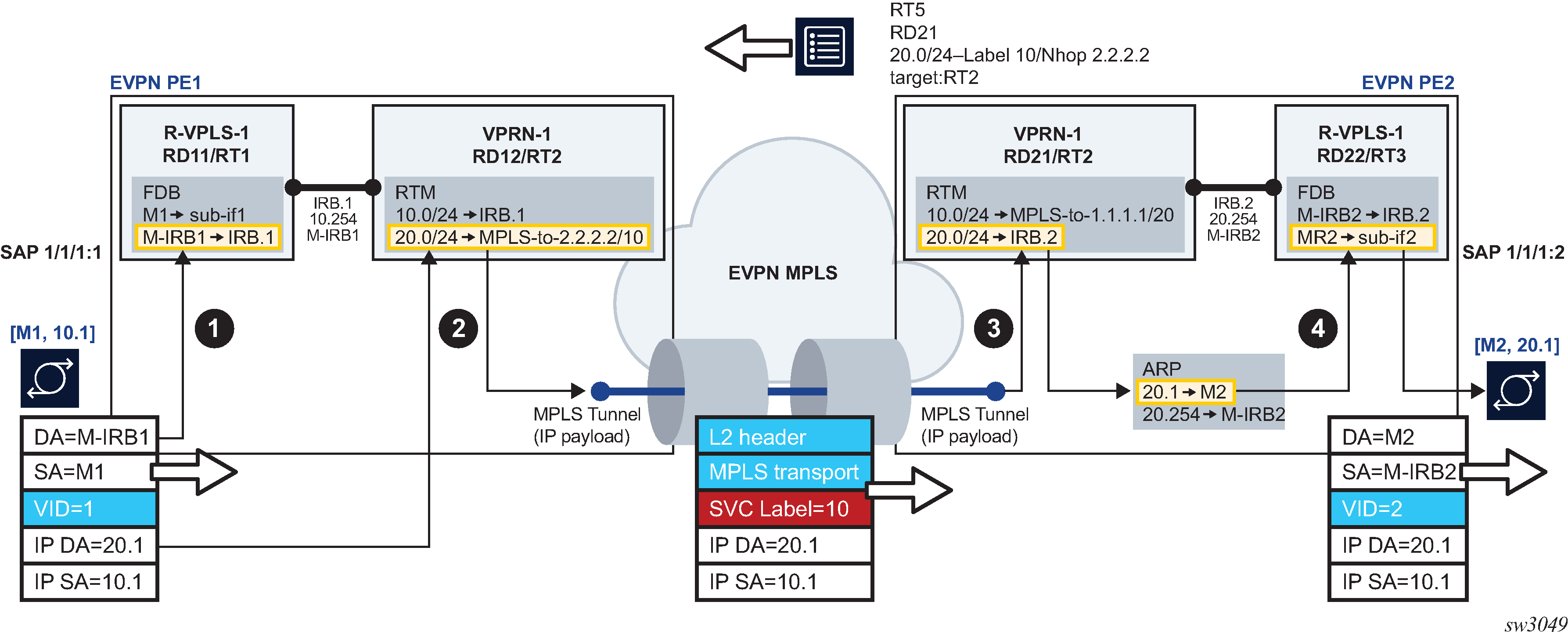
EVPN IFL uses EVPN IP Prefix routes to exchange prefixes between PEs without the need for an R-VPLS service, termed Supplementary Broadcast Domain (SBD) in the standards, and any destination MAC lookup. The EVPN IFL uses the same datapath that is used for IP-VPN services in the VPRN.
In the example shown in Interface-less IP-VRF-to-IP-VRF model for IP encapsulation in MPLS tunnels, the following applies.
-
PE2 advertises IP Prefix 20.0/24 (shorthand for 20.0.0.0/24) in an EVPN IP Prefix route that no longer contains a router's MAC extended community. In step 1, per usual processing, arriving frames with IP destination 20.0.0.1 on PE1's R-VPLS-1 are processed for a route lookup on VPRN-1.
-
In step 2, in contrast to and as opposed to the other EVPN Layer 3 models, the lookup yields a route-table entry that does not point at an SBD R-VPLS, but points instead to an MPLS tunnel terminated on PE2. PE1 then pushes the EVPN service label received on the IP Prefix route at the top of the IP packet, and the packet is sent on the wire without an inner Ethernet header.
-
In step 3, the MPLS tunnel is terminated on PE2 and the EVPN label identifies the VPRN-1 service for a route lookup.
-
In Step 4, the processing corresponds to the regular R-VPLS forwarding that occurs in the other EVPN Layer 3 models.
Use the vprn>bgp-evpn>mpls context to configure a VPRN service for EVPN IFL with MPLS encapsulation. This context which is similar to the existing contexts in VPLS and Epipe services, enables the use of EVPN IFL in the VPRN service. When this context is enabled, no R-VPLS with evpn-tunnel should be added to the VPRN; that is, the user must ensure that no SBD is configured. For example, in Interface-less IP-VRF-to-IP-VRF model for IP encapsulation in MPLS tunnels, PE1 and PE2 VPRN-1 services are configured as follows.
[ex:configure service vprn "vprn-1"]
A:admin@PE1# info
    admin-state enable
    ecmp 2
    bgp-evpn {
        mpls 1 {
            admin-state enable
            route-distinguisher "192.0.2.1:12"
            vrf-target {
                community "target:64500:2"
            }
            auto-bind-tunnel {
                resolution any
            }
        }
    }
    interface "irb-1" {
        ipv4 {
            primary {
                address 10.0.0.254
                prefix-length 24
            }
        }
        vpls "r-vpls-1" {
        }
    }
[ex:configure service vprn "vprn-1"]
A:admin@PE2# info
    admin-state enable
    ecmp 2
    bgp-evpn {
        mpls 1 {
            admin-state enable
            route-distinguisher "192.0.2.2:21"
            vrf-target {
                community "target:64500:2"
            }
            auto-bind-tunnel {
                resolution any
            }
        }
    }
    interface "irb-2" {
        ipv4 {
            primary {
                address 20.0.0.254
                prefix-length 24
            }
        }
        vpls "r-vpls-1" {
        }
    }
EVPN MAC/IP advertisement route install into the route table
SR OS supports the symmetric IRB model specified in RFC 9135, by which, when enabled, the router advertises the learned MAC and IP addresses of a host in an EVPN MAC/IP Advertisement route. This route contains not only the label and route target of the R-VPLS service where the host is learned, but also the label and the route target of the VPRN attached to the R-VPLS service. This is possible because the MAC/IP Advertisement route contains two labels in the NLRI: label-1 (for Layer 2 purposes) and label-2 (for Layer 3 purposes).
On reception, the remote router receives the EVPN MAC/IP Advertisement route and programs the IP address as a host route (/32 or /128) in the VPRN route table. Although host routes can be advertised in IP-Prefix routes, the symmetric IRB model allows the advertisement of the MAC and host IP information in a single NLRI. The following figure shows this model.
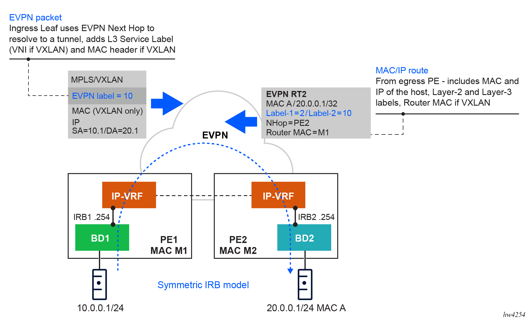
configure service interface vpls evpn arp advertise interface-less-routing bgp-evpn-instance
configure service interface vpls evpn nd advertise interface-less-routing bgp-evpn-instance- MD-CLI
[ex:/configure service vprn "EVPN-IFL-HOST-200"] A:admin@node-2# info admin-state enable service-id 200 customer "1" bgp-evpn { mpls 1 { admin-state enable route-distinguisher "192.0.2.2:200" evi 200 vrf-target { community "target:64500:200" } auto-bind-tunnel { resolution any } } } interface "BD-201" { ipv4 { primary { address 10.0.0.254 prefix-length 24 } neighbor-discovery { learn-unsolicited true proactive-refresh true static-neighbor 10.0.0.100 { mac-address 00:de:ad:be:ef:00 } } vrrp 1 { backup [10.0.0.254] owner true passive true } } vpls "BD-201" { evpn { arp { learn-dynamic false advertise static { route-tag 200 interface-less-routing { } } advertise dynamic { route-tag 200 interface-less-routing { } } } } } } - Classic
CLI
A:node-2# configure service vprn 200
A:node-2>config>service>vprn# info
----------------------------------------------
            interface "BD-201" create
                address 10.0.0.254/24
                arp-learn-unsolicited
                arp-proactive-refresh
                static-arp 10.0.0.100 00:de:ad:be:ef:00
                vrrp 1 owner passive
                    backup 10.0.0.254
                exit
                vpls "BD-201"
                    evpn
                        arp
                            no learn-dynamic
                            advertise static route-tag 200 interface-less-routing bgp-evpn-instance 1
                            advertise dynamic route-tag 200 interface-less-routing bgp-evpn-instance 1
                        exit
                    exit
                exit
            exit
            bgp-evpn
                mpls
                    auto-bind-tunnel
                        resolution any
                    exit
                    evi 200
                    route-distinguisher 192.0.2.2:200
                    vrf-target target:64500:200
                    no shutdown
                exit
            exit
            no shutdown
----------------------------------------------
The IP addresses received in MAC/IP Advertisement routes with non-zero label-2 and the VPRN route target are programmed in the route table of the receiving router with route owner EVPN-IFL-HOST, as follows.
Use the following command to display route table information.
show router 200 route-table 10.0.0.202/32===============================================================================
Route Table (Service: 200)
===============================================================================
Dest Prefix[Flags] Type Proto Age Pref
Next Hop[Interface Name] Metric
-------------------------------------------------------------------------------
10.0.0.202/32 Remote EVPN-IFL* 00h04m11s 170
2001:db8::2 (tunneled) 10
-------------------------------------------------------------------------------
No. of Routes: 1
Flags: n = Number of times nexthop is repeated
B = BGP backup route available
L = LFA nexthop available
S = Sticky ECMP requested
===============================================================================
* indicates that the corresponding row element may have been truncated.Use the following command to display extensive route table information.
show router 200 route-table 10.0.0.202/32 extensive===============================================================================
Route Table (Service: 200)
===============================================================================
Dest Prefix : 10.0.0.202/32
Protocol : EVPN-IFL-HOST
Age : 00h04m18s
Preference : 170
Indirect Next-Hop : 2001:db8::2
Label : 524280
VPN Next-Hop Index : 10
QoS : Priority=n/c, FC=n/c
Source-Class : 0
Dest-Class : 0
ECMP-Weight : N/A
Resolving Next-Hop : 2001:db8::2 (LDP tunnel)
Metric : 10
ECMP-Weight : N/A
-------------------------------------------------------------------------------
No. of Destinations: 1
===============================================================================- MD-CLI
configure policy-options policy-statement entry from protocol name - classic
CLI
configure router policy-options policy-statement entry from protocol evpn-ifl-host
ARP-ND host routes for extended Layer 2 data centers
SR OS supports the creation of host routes for IP addresses that are present in the ARP or neighbor tables of a routing context. These host routes, also called ARP-ND routes, can be advertised using EVPN or IP-VPN families. The following figure shows a typical use case where ARP-ND routes are used for extension of Layer 2 data centers (DCs).
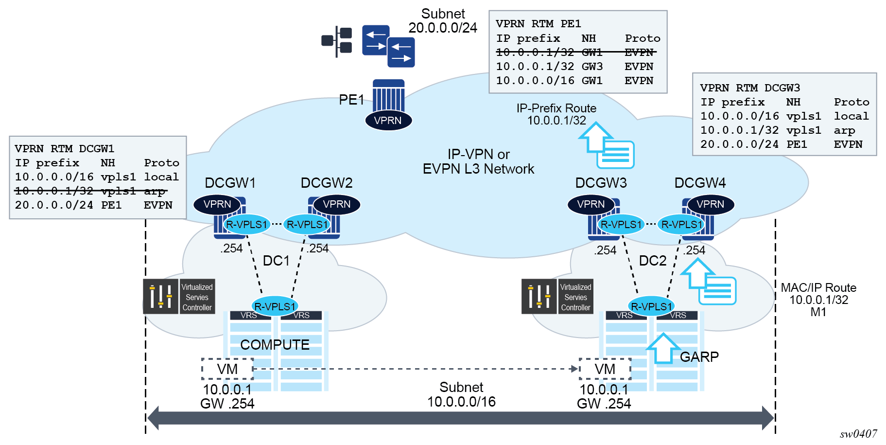
Subnet 10.0.0.0/16 in the preceding figure is extended throughout two DCs. The DC gateways are connected to the users of subnet 20.0.0.0/24 on PE1 using IP-VPN (or EVPN). If the virtual machine VM 10.0.0.1 is connected to DC1, PE1 performs a longest prefix match (LPM) lookup on the VPRN’s route table when it needs to send traffic to host 10.0.0.1. If the only IP prefix advertised by the four DC GWs was 10.0.0.0/16, PE1 could send the packets to the DC where the VM is not present.
To provide efficient downstream routing to the DC where the VM is located, DCGW1 and DCGW2 must generate host routes for the VMs to which they connect. When the VM moves to the other DC, DCGW3 and DCGW4 must be able to learn the VM’s host route and advertise it to PE1. DCGW1 and DCGW2 must withdraw the route for 10.0.0.1, because the VM is no longer in the local DC.
In this case, SR OS is able to learn the VM’s host route from the generated ARP/ND messages when the VM boots or moves.
A route owner type called ‟ARP-ND” is supported in the base or VPRN route table. The ARP-ND host routes have a preference of 1 in the route table and are automatically created from the ARP/ND neighbor entries in the router instance.
The following commands enable ARP-ND host routes to be created in the applicable route tables:
config service vprn/ies interface arp-host-route populate {evpn | dynamic | static}
config service vprn/ies interface ipv6 nd-host-route populate {evpn | dynamic | static}
When the config service vprn/ies interface arp-host-route populate command is enabled, the EVPN, dynamic, and static ARP entries of the routing context create ARP-ND host routes in the route table. Similarly, ARP-ND host routes are created in the IPv6 route table from static, dynamic, and EVPN neighbor entries if the config service vprn/ies interface ipv6 nd-host-route populate command is enabled.
The arp-host-route populate and nd-host-route populate commands are used with the following features:
adding ARP-ND hosts
A route tag can be added to ARP-ND hosts using the route-tag commands. This tag can be matched on BGP VRF export and peer export policies.
keeping entries active
The ARP-ND host routes are kept in the route table as long as the corresponding ARP or neighbor entry is active. Even if there is no traffic destined for them, the arp-proactive-refresh and nd-proactive-refresh commands configure the node to keep the entries active by sending an ARP refresh message 30 seconds before the arp-timeout or starting a confirmation message (NUD) when the stale time expires.
speeding up learning
Configure the arp-learn-unsolicited and nd-learn-unsolicited commands to speed up the learning of the ARP-ND host routes. When arp-learn-unsolicited is enabled, received unsolicited ARP messages (typically GARPs) create an ARP entry; consequently, an ARP-ND route is created if arp-host-route populate is enabled. Similarly, unsolicited Neighbor Advertisement messages create a stale neighbor. If nd-host-route populate is enabled, NUD is sent for all the neighbor entries created as stale, and, if confirmed, the corresponding ARP-ND routes are added to the route table.
In Extended Layer 2 data centers, enabling the arp-host-route populate command on the DCGWs allows them to learn or advertise the ARP-ND host route 10.0.0.1/32 when the VM is locally connected and to remove or withdraw the host routes when the VM is no longer present in the local DC.
ARP-ND host routes installed in the route table can be exported to VPN IPv4, VPN IPv6, or EVPN routes. No other BGP families or routing protocols are supported.
EVPN host mobility procedures within the same R-VPLS service
EVPN host mobility is supported in SR OS in accordance with Section 4 of draft-ietf-bess-evpn-inter-subnet-forwarding. When a host moves from a source PE to a target PE, it can behave in one of the following ways.
The host initiates an ARP request or GARP upon moving to the target PE.
The host sends a data packet without first initiating an ARP request of GARP.
The host is silent.
EVPN host mobility configuration
The following figure shows an example of a host connected to a source PE, PE1, that moved to the target, PE2. The figure shows the expected configuration on the VPRN interface, where R-VPLS 1 is attached (for both PE1 and PE2). PE1 and PE2 are configured with an anycast gateway, that is, a VRRP passive instance with the same backup MAC and IP in both PEs.
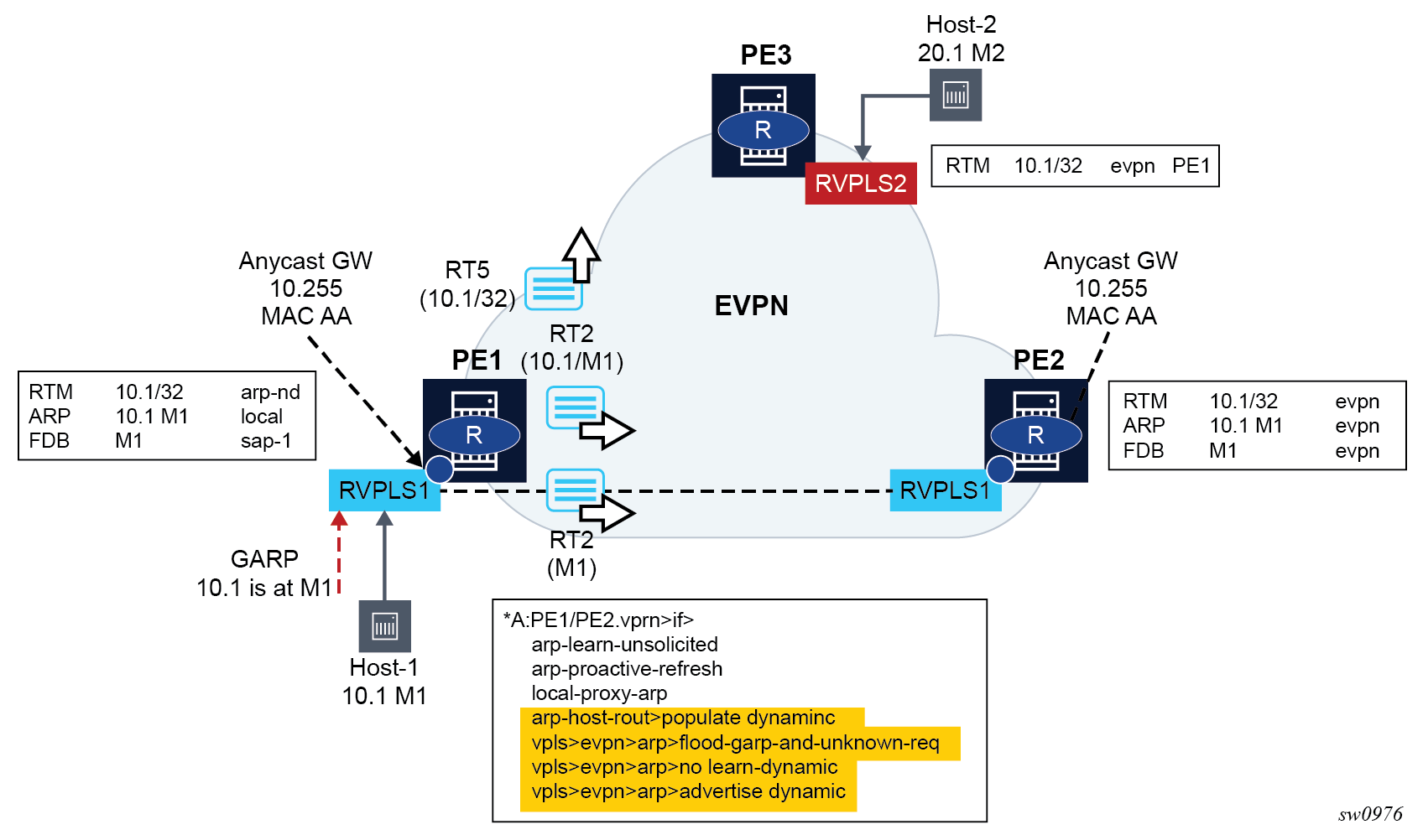
In this initial phase:
PE1 learns Host-1 IP to MAC (10.1-M1) in the ARP table and generates a host route (RT5) for 10.1/32 because Host-1 is locally connected to PE1. In particular:
arp-learn-unsolicited triggers the learning of 10.1-M1 upon receiving a GARP from Host-1 or any other ARP
arp-proactive-refresh triggers the refresh of the host-1 ARP entry 30 seconds before the entry ages out
local-proxy-arp ensures that PE1 replies to any received ARP request on behalf of other hosts in the R-VPLS
arp-host-route populate dynamic ensures that only the dynamically learned ARP entries create a host route, for example, 10.1
no flood-garp-and-unknown-req suppresses ARP flooding (from the CPM) within the R-VPLS1 context, and because ARP entries are synchronized via EVPN, reduces significantly the unnecessary ARP flooding
advertise dynamic triggers the advertisement of MAC/IP routes for the dynamic ARP entries, including the IP and MAC addresses, for example, 10.1-M1; a MAC/IP route for M1-only that has been previously advertised as M1 is learned on the FDB as local or dynamic
PE2 learns Host-1 10.1-M1 in the ARP and FDB tables as EVPN type. PE2 must not learn 10.1-M1 as dynamic so that PE2 is prevented from advertising an RT5 for 10.1/32. If PE2 advertises 10.1/32, PE3 could select PE2 as the next hop to reach Host-1, creating an undesired hair-pinning forwarding behavior. PE2 is expected to have the same configuration as PE1, including the following commands, as well as those described for PE1:
no learn-dynamic prevents PE2 from learning ARP entries from ARP traffic received on an EVPN tunnel
populate dynamic, as in PE1, ensures PE2 only creates route-table ARP-ND host routes for dynamic entries. Therefore, 10.1-M1 does not create a host route as long as it is learned via EVPN only.
The configuration described in this section and the cases described in Host mobility case 1, Host mobility case 2, and Host mobility case 3 apply to IPv4 hosts; however, the functionality is also supported for IPv6 hosts. The IPv6 configuration requires equivalent commands that use the prefix ‟nd-” instead of ‟arp-”. The only exception is the flood-garp-and-unknown-req command, which does not have an equivalent command for ND.
Host mobility case 1
Host initiates an ARP/GARP upon moving to the target PE
Host mobility within the same R-VPLS – move with GARP shows the case where the host initiates an ARP/GARP upon moving to the target PE. The following is the expected behavior based on the configuration described in EVPN host mobility configuration.
Host-1 moves from PE1 to PE2 and issues a GARP with 10.1-M1.
Upon receiving the GARP, PE2 updates its FDB and ARP table.
The route-table entry for 10.1/32 changes from EVPN to type ARP-ND (based on populate dynamic); consequently, PE2 advertises a RT5 with 10.1/32. Also, M1 is now learned in the FDB and ARP as local; consequently, MAC/IP routes with a higher sequence number are advertised (one MAC/IP route with M1 only and another MAC/IP route with 10.1-M1).
Upon receiving the routes, PE1 performs the following actions:
updates its FDB and withdraws its RT2(M1) based on the higher SEQ number
updates its ARP entry 10.1-M1 from dynamic to type evpn
as a result of populate dynamic, removes its ARP-ND host from the route-table and withdraws its RT5 for 10.1/32
The move of 10.1-M1 from dynamic to evpn triggers an ARP request from PE1 asking for 10.1. The no flood-garp-and-unknown-req command prevents PE1 from flooding the ARP request to PE2.
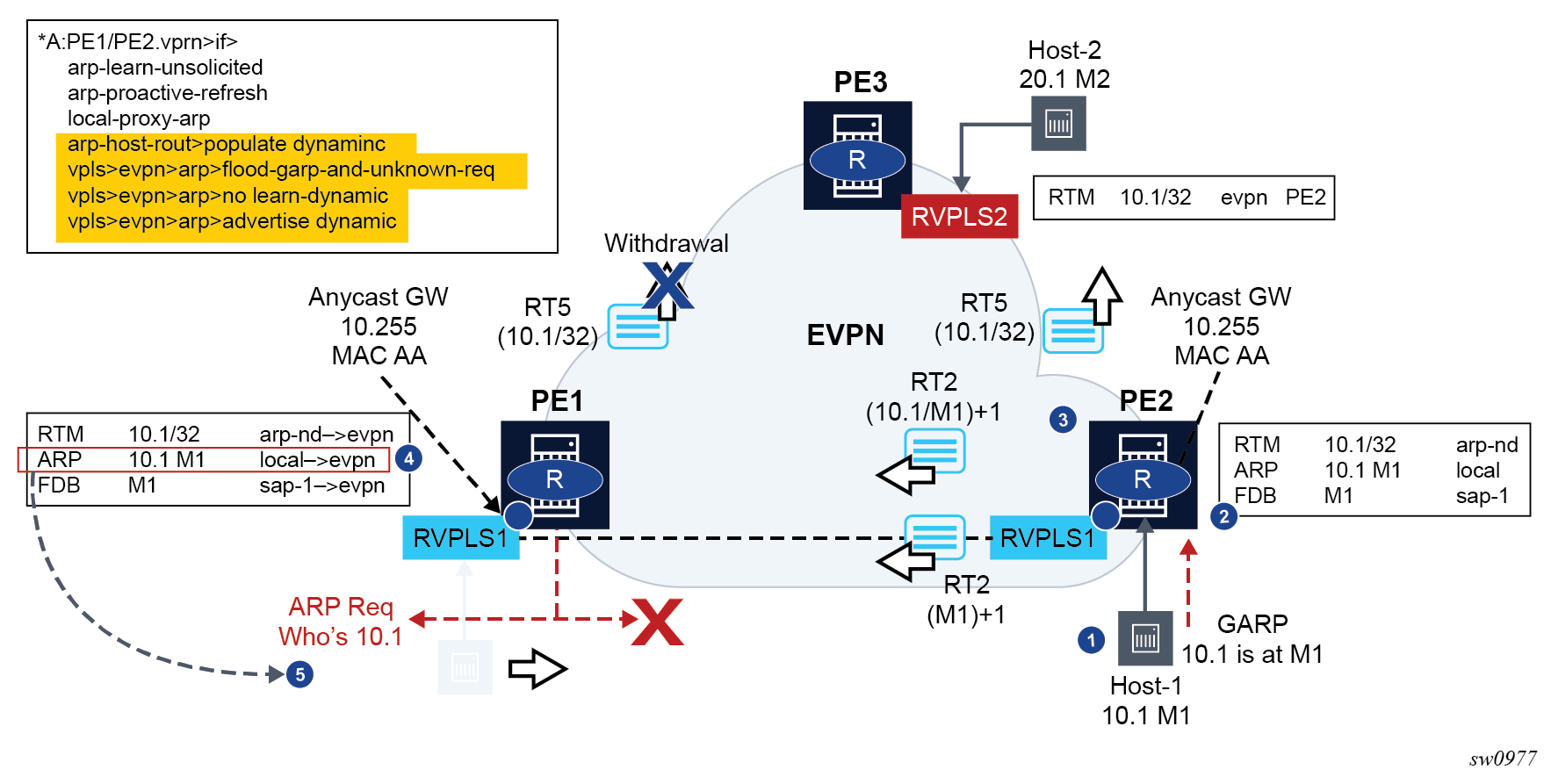
After step 5 is complete, the process ends if no host replies to the PE1 ARP request; however, if a host replied to the ARP for 10.1, the process starts again.
Host mobility case 2
Host sends a data packet upon a move to target PE
In this case, the host does not send a GARP/ARP packet when moving to the target PE. Only regular data packets are sent. Host mobility within the same R-VPLS – move with data packet shows the case where a host sends a data packet upon a move to the target PE.
Host-1 moves from PE1 to PE2 and issues a non-ARP frame with MAC SA=M1.
-
When receiving the frame, PE2 updates its FDB and starts the mobility procedures for M1 (because it was previously learned from EVPN). At the same time, PE2 also creates a short-lived dynamic ARP entry for the host, and triggers an ARP request for it.
PE2 advertises a RT2 with M1 only, and a higher sequence number.
PE1 receives the RT2, updates its FDB, and withdraws its RT2s for M1 (this includes the RT2 with M1-only and the RT2 with 10.1-M1).
PE1 issues an ARP request for 10.1, triggered by the update on M1.
In this case, the PEs are configured with flood-garp-and-unknown-req and, therefore, the generated ARP request is flooded to local SAP and SDP-binds and EVPN destinations. When the ARP request is arrives at PE2, it is flooded to the PE2 SAP and SDP-binds and received by Host-1.
Host-1 sends an ARP reply that is snooped by PE2 and triggers a similar process described in Host mobility case 1 (as shown in Host mobility within the same R-VPLS – move with data packet).
Because passive VRRP is used in this scenario, the ARP reply uses the anycast backup MAC that is consumed by PE2.
Upon receiving the ARP reply, PE2 updates its ARP table to dynamic.
Because the route-table entry for 10.1/32 changes from EVPN to type ARP-ND (based on populate dynamic), PE2 advertises a RT5 with 10.1/32. Also, M1 is now learned in ARP as local, therefore a RT2 for 10.1-M1 is sent (the sequence number follows the RT2 with M1 only).
Upon receiving the route, PE1 performs the following actions:
updates the ARP entry 10.1-M1, from type local to type evpn
as a result of populate dynamic, removes its ARP-ND host from the route-table and withdraws its RT5 for 10.1/32
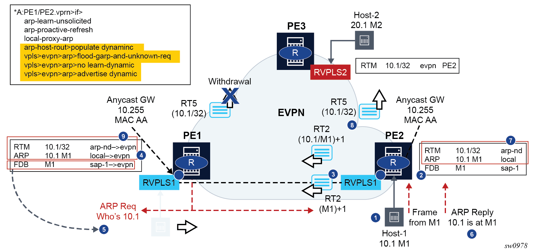
Host mobility case 3
Silent host upon a move to the target PE
This case assumes the host moves but it stays silent after the move. Host mobility within the same R-VPLS – silent host shows a silent host upon a move to the target PE.
Host-1 moves from PE1 to PE2 but remains silent.
Eventually, M1 ages out in PE1’s FDB and the RT2s for M1 are withdrawn. This update on M1 triggers PE1 to issue an ARP request for 10.1.
The flood-garp-and-unknown-req command is configured. The ARP request makes it to PE2 and Host-1.
Host-1 sends an ARP reply that is consumed by PE2. FDB and ARP tables are updated.
The FDB and ARP updates trigger RT2s with M1-only and with 10.1-M1. Because an ARP-ND dynamic host route is also created in the route-table, an RT5 with 10.1/32 is triggered.
Upon receiving the routes, PE1 updates the FDB and ARP tables. The update on the ARP table from dynamic to evpn removes the host route from the route-table and withdraws the RT5 route.
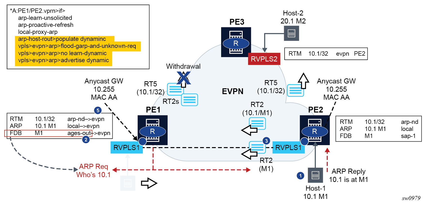
BGP and EVPN route selection for EVPN routes
When two or more EVPN routes are received at a PE, BGP route selection typically takes place when the route key or the routes are equal. When the route key is different, but the PE has to make a selection (for example, the same MAC is advertised in two routes with different RDs), BGP hands over the routes to EVPN and the EVPN application performs the selection.
The following EVPN and BGP selection criteria apply for EVPN routes.
-
EVPN route selection for MAC routes
When two or more routes with the same mac-length/mac but different route key are received, BGP transfers the routes to EVPN. EVPN selects the route based on the following tie-breaking order:
-
conditional static MACs (local protected MACs)
-
auto-learned protected MACs (locally learned MACs on SAPs or mesh/spoke-SDPs as a result of the configuration of auto-learn-mac-protect)
-
EVPN ES PBR MACs
-
EVPN static MACs (remote protected MACs)
-
data plane learned MACs (regular learning on SAPs or SDP bindings) and EVPN MACs with higher SEQ numbers. Learned MACs and EVPN MACs are considered equal if they have the same SEQ number.
-
EVPN MACs with higher SEQ number
-
EVPN E-Tree root MACs
-
EVPN non-RT-5 MACs (this tie-breaking rule is only observed if the selection algorithm is comparing received MAC routes and internal MAC routes derived from the MACs in IP-Prefix routes, such as RT-5 MACs)
-
lowest IP (next-hop IP of the EVPN NLRI)
-
lowest Ethernet tag (that is zero for MPLS and may be different from zero for VXLAN)
-
lowest RD
-
lowest BGP instance (this tie-breaking rule is only considered if the preceding rules fail to select a unique MAC and the service has two BGP instances of the same encapsulation)
-
-
ES PBR MAC routes
When a PBR filter with a forward action to an ESI and Service Function IP (SF-IP) exists, a MAC route is created by the system. This MAC route is compared to other MAC routes received from BGP.
When static, EVPN, or dynamic ARP resolves for an SF-IP and the system has an AD EVI route for the ESI, a MAC route is created by ES PBR with the <MAC Address = ARPed MAC Address, VTEP = AD EVI VTEP, VNI = AD EVI VNI, RD = ES PBR RD (special RD), Static = 1> and installed in EVPN.
-
This MAC route does not add anything back to ARP; however, it goes through the MAC route selection in EVPN and triggers the FDB addition if it is the best route.
-
In terms of priority, this route priority is lower than local static but higher than remote EVPN static.
-
If there are two competing ES PBR MAC routes, then the selection goes through the rest of checks (Lowest IP > Lowest RD).
-
- EVPN route selection for EVPN AD per-EVI routes
-
The BGP route selection for MAC routes with the same route-key follows the following priority order:
-
EVPN static MACs (remote protected MACs)
-
EVPN MACs with higher sequence number
-
regular BGP selection (local-pref, aigp metric, shortest as-path, …, lowest IP)
-
-
The BGP route selection for the rest of the EVPN routes follows regular BGP selection.
If BGP runs through the selection criteria and a specified and valid EVPN route is not selected in favor of another EVPN route, the non-selected route is displayed using the show router bgp routes evpn evpn-type detail command with a tie-breaker reason.
Protected MACs do not overwrite EVPN static MACs. If a MAC is in the FDB and protected because it was received with the sticky/static bit set in a BGP EVPN update, and a frame is received with the source MAC on an object configured with auto-learn-mac-protect, that frame is dropped as a result of the implicit restrict-protected-src discard-frame. The reverse is not true; when a MAC is learned and protected using auto-learn-mac-protect, its information is not overwritten with the contents of a BGP update containing the same MAC address.
LSP tagging for BGP next-hops or prefixes and BGP-LU
It is possible to constrain the tunnels used by the system for resolution of BGP next-hops or prefixes and BGP labeled unicast routes using LSP administrative tags. See ‟LSP Tagging and Auto-Bind Using Tag Information” in the 7705 SAR Gen 2 MPLS Guide for further details.
Oper-groups interaction with EVPN services
Operational groups, also referred to as oper-groups, are supported in EVPN services. In addition to supporting SAP and SDP-binds, oper-groups can also be configured under the following objects:
-
EVPN-MPLS instances
-
Ethernet segments
These oper-groups can be monitored in LAGs or service objects. Oper-groups are particularly useful for the following applications:
Link Loss Forwarding (LLF) for EVPN VPWS services
core isolation blackhole avoidance
LAG standby signaling to CE on non-DF EVPN PEs (single-active)
LAG-based LLF for EVPN-VPWS services
SR OS uses the Eth-CFM fault-propagation to support CE-to-CE fault propagation in EVPN-VPWS services. That is, upon detecting a CE failure, an EVPN-VPWS PE withdraws the corresponding Auto-Discovery per-EVI route, which then triggers a down maintenance endpoint (MEP) on the remote PE that signals the fault to the connected CE. In cases where the CE connected to EVPN-VPWS services does not support Eth-CFM, the fault can be propagated to the remote CE by using LAG standby-signaling, which can be LACP-based or simply power-off.
The following figure shows an example of link loss forwarding for EVPN-VPWS.
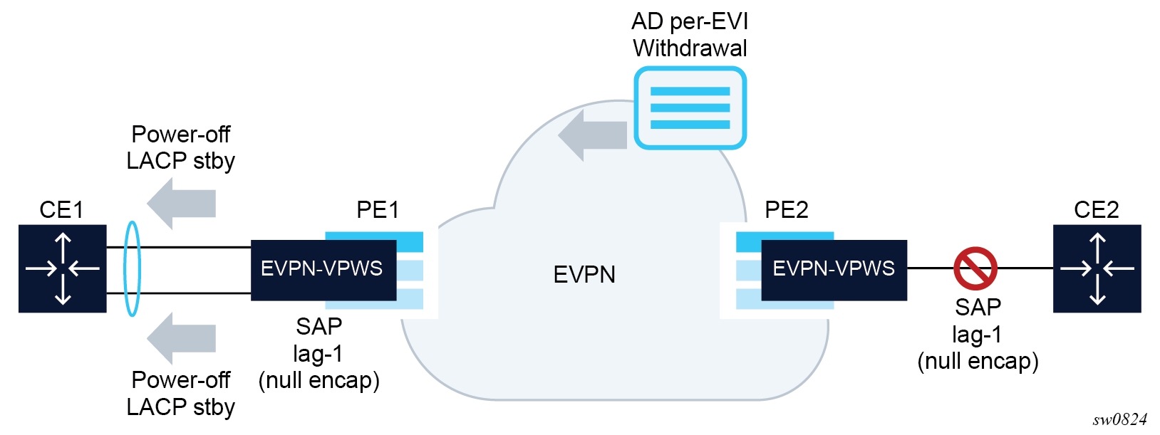
In this example, PE1 is configured as follows:
A:PE1>config>lag(1)# info
----------------------------------------------
mode access
encap-type null
port 1/1/1
port 1/1/2
standby-signaling power-off
monitor-oper-group "llf-1"
no shutdown
----------------------------------------------
*A:PE1>config>service>epipe# info
----------------------------------------------
bgp
exit
bgp-evpn
    evi 1
    local-attachment-circuit ac-1
        eth-tag 1
        exit
    remote-attachment-circuit ac-2
        eth-tag 2
        exit
    mpls bgp 1
        oper-group "llf-1"
        auto-bind-tunnel
            resolution any
        exit
        no shutdown
    exit
sap lag-1 create
no shutdown
exit
no shutdown
The following applies to the PE1 configuration.
The EVPN Epipe service is configured on PE1 with a null LAG SAP and the oper-group ‟llf-1” under bgp-evpn>mpls. This is the only member of oper-group ‟llf-1”.
Note: Do not configure the oper-group under config>service>epipe, because circular dependencies are created when the access SAPs go down as a result of the LAG monitor-oper-group command.The oper-group monitors the status of the BGP-EVPN instance in the Epipe service. The status of the BGP-EVPN instance is determined by the existence of an EVPN destination at the Epipe.
The LAG, in access mode and encap-type null, is configured using the command monitor-oper-group ‟llf-1”.
Note: The configure lag monitor-oper-group name command is only supported in access mode. Any encapsulation type can be used.
As shown in Link loss forwarding for EVPN-VPWS, upon failure on CE2, the following events occur.
PE2 withdraws the EVPN route.
The EVPN destination is removed in PE1 and oper-group ‟llf-1” also goes down.
Because lag-1 is monitoring ‟llf-1”, the oper-group that is becoming inactive triggers standby signaling on the LAG; that is, power-off or LACP out-of-sync signaling to the CE1.
Because the SAP or port is down as a result of the LAG monitoring of the oper-group, PE1 does not trigger an AD per-EVI route withdrawal, even if the SAP is brought operationally down.
After CE2 recovers and PE2 re-advertises the AD per-EVI route, PE1 creates the EVPN destination and oper-group ‟llf-1” comes up. As a result, the monitoring LAG stops signaling standby and the LAG is brought up.
Core isolation blackhole avoidance
The following figure shows how black holes can be avoided when a PE becomes isolated from the core.
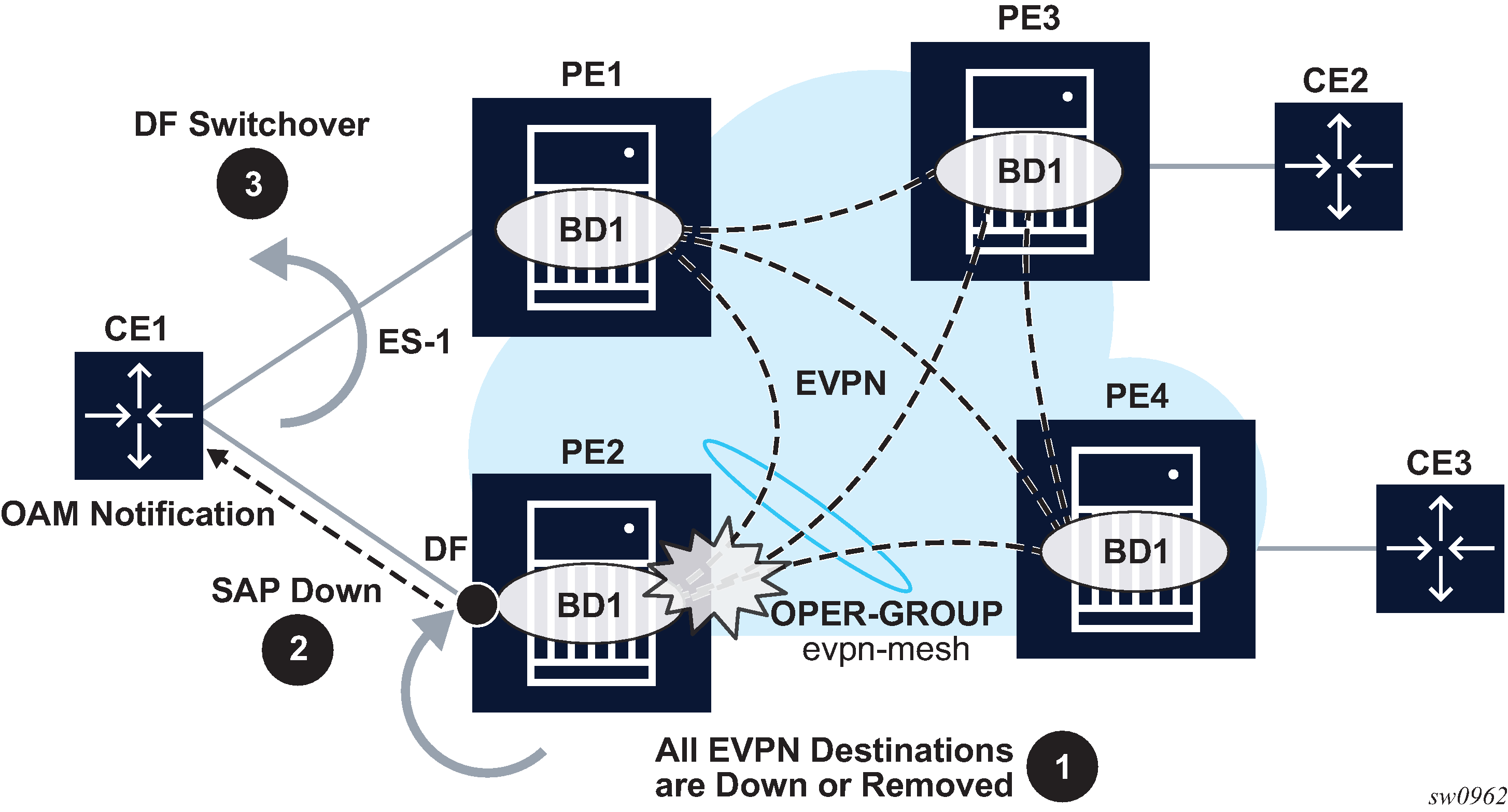
In this example, consider PE2 and PE1 are single-active multihomed to CE1. If PE2 loses all its core links, PE2 must somehow notify CE1 so that PE2 does not continue attracting traffic and so that PE1 can take over. This notification is achieved by using oper-groups under the BGP-EVPN instance in the service. The following is an example output of the PE2 configuration.
*[ex:configure service vpls ”evi1"]
A:admin@PE-2# info
    admin-state enable
    bgp-evpn {
        evi 1
        mpls 1 {
            admin-state enable
            oper-group ‟evpn-mesh”
            auto-bind-tunnel {
                resolution any
            }
        }
    }
    sap lag-1:351 {
        monitor-oper-group ‟evpn-mesh”
            }
*[ex:configure service oper-group ”evpn-mesh"]
A:admin@PE-2# info detail
    hold-time {
        up 4
    }
With the PE2 configuration and Core isolation blackhole avoidance example, the following steps occur.
PE2 loses all its core links, therefore, it removes its EVPN-MPLS destinations. This causes oper-group ‟evpn-mesh” to go down.
Because PE2 is the DF in the Ethernet Segment (ES) ES-1 and sap lag-1:351 is monitoring the oper-group, the SAP becomes operationally down. If ETH-CFM fault propagation is enabled on a down MEP configured on the SAP, CE1 is notified of the failure.
PE1 takes over as the DF, based on the withdrawal of the ES (and AD) routes from PE2, and CE1 begins sending traffic immediately to PE1 only, therefore, avoiding a traffic black hole.
Generally, when oper-groups are associated with EVIs, the following applies.
-
The oper-group state is determined by the existence of at least one EVPN destination in the EVPN instance.
-
The oper-group that is configured under a BGP EVPN instance cannot be configured under any other object (for example, SAP, SDP binding, and so on) of the same or different service.
- The status of an oper-group associated with an EVPN instance does not go down if all the EVPN destinations are operationally down because of a control word or MTU mismatch.
-
The status of an oper-group associated with an EVPN instance goes down in the following cases:
-
the service admin-state is disabled (only for VPLS services, not for Epipes)
-
the BGP EVPN VXLAN or MPLS admin-state are disabled
-
there are no EVPN destinations associated with the instance
-
LAG or port standby signaling to the CE on non-DF EVPN PEs (single-active)
As described in EVPN for MPLS tunnels, EVPN single-active multihoming PEs that are elected as non-DF must notify their attached CEs so the CE does not send traffic to the non-DF PE. This can be performed on a per-service basis that is based on the ETH-CFM and fault-propagation. However, sometimes ETH-CFM is not supported in multihomed CEs and other notification mechanisms are needed, such as LACP standby or power-off. This scenario is shown in the following figure.
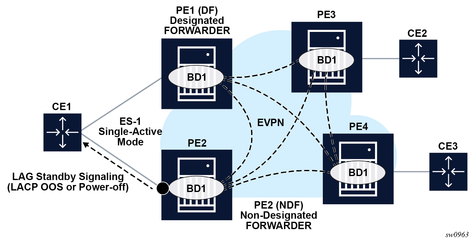
As shown in the preceding figure, the multihomed PEs are configured with multiple EVPN services that use ES-1. ES-1 and its associated LAG is configured as follows.
*[ex:configure lag 1]
A:admin@PE-2# info
    admin-state enable
    standby-signaling {power-off|lacp}
    monitor-oper-group ”DF-signal-1"
    mode access
    port 1/1/c2/1 {
    }
<snip>
ex:configure service system bgp evpn]
A:admin@PE-2# info
    ethernet-segment "ES-1" {
        admin-state enable
        esi 0x01010000000000000000
        multi-homing-mode single-active
        oper-group ‟DF-signal-1”
        association {
            lag 1 {
            }
<snip>
The following applies when the operational group is configured on the ES and monitored on the associated LAG.
The operational group status is driven by the ES DF status (defined by the number of DF SAPs or oper-up SAPs owned by the ES).
The operational group goes down if all the SAPs in the ES go down (this happens in PE2 in LACP standby signaling from the non-DF). The ES operational group goes up when at least one SAP in the ES goes up.
As a result, if PE2 becomes non-DF on all the SAPs in the ES, they all go oper-down, including the ES-1 operational group.
Because LAG-1 is monitoring the operational group, when its status goes down, LAG-1 signals LAG standby state to the CE. The standby signaling can be configured as LACP or power-off.
The ES and AD routes for the ES are not withdrawn because the router recognizes that the LAG becomes standby as a result of the ES operational group.
If the single-active ES is associated with a port instead of a LAG, the config>port>monitor-oper-group DF-signal-1 command can be configured. In this case, the port monitors the ES operational group and the following rules apply:
- As in the case of the LAG, if the ES goes non-DF, its operational group also goes down.
- The port that is monitoring the ES operational group signals standby state by powering off the port itself.
- As in the case of the LAG, the ES and AD routes for the ES are not withdrawn because the router recognizes that the port is in standby state because of the ES operational group.
Operational groups cannot be assigned to ESs that are configured as virtual, all-active or service-carving mode auto.
AC-influenced DF election capability on an ES with oper-group
The AC-influenced designated forwarder (AC-DF) election capability, as described in RFC 8584, is supported in SR OS. By default, the ac-df-capability command is set to the include option. This configuration addresses the need to consider EVPN Auto-discovery per EVI/ES (AD per EVI/ES) routes for a specific PE, which ensures that the PE is included on the candidate DF list.
Configuring ac-df-capability to exclude disables the AC-DF capability. When ac-df-capability exclude is configured on a specific ES, the presence or absence of the AD per EVI/ES routes from the ES peers does not modify the DF Election candidate list for the ES. The exclude option is recommended in ESs that use an oper-group, which is monitored by the access LAG, to signal standby lacp or power-off, as described in LAG or port standby signaling to the CE on non-DF EVPN PEs (single-active). All PE routers attached to the same ES must be configured consistently for the specific ac-df-capability.
EVPN Layer-2 multicast (IGMP/MLD proxy)
SR OS supports EVPN Layer-2 multicast as described in the EVPN IGMP/MLD Proxy specification RFC 9251. When this is enabled in a VPLS service with active IGMP or MLD snooping, IGMP or MLD messages are no longer sent to EVPN destinations. SMET routes (EVPN routes type 6) are advertised instead, so that the interest in a specific (S,G) can be signaled to the rest of the PEs attached to the same VPLS (also known as a Broadcast Domain (BD)). The following figure shows this scenario.
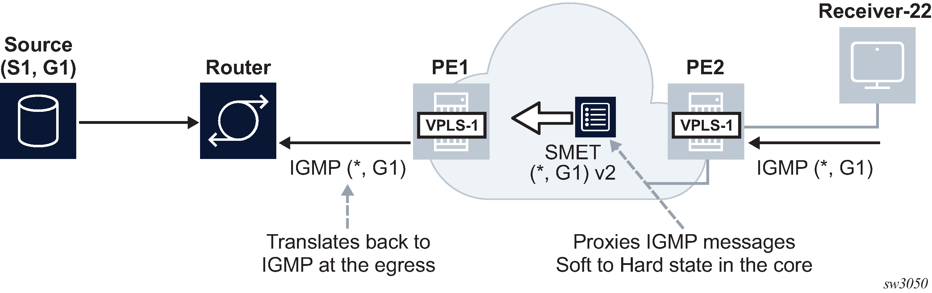
A VPLS service supporting EVPN-based proxy-IGMP/MLD functionality is configured as follows.
vpls 1 name "evi-1" customer 1 create
            bgp
            exit
            bgp-evpn
                evi 1
                sel-mcast-advertisement
                vxlan
                    shutdown
                exit
                mpls
                    auto-bind-tunnel
                        resolution any
                    exit
                    no shutdown
                exit
            exit
            igmp/mld-snooping
                evpn-proxy
                    no shutdown
                exit
            sap lag-1:101 create
                igmp-snooping
                    send-queries
                exit
                no shutdown
            exit
Where:
- The sel-mcast advertise (MD-CLI) or sel-mcast-advertisement (classic CLI) command allows the advertisement of SMET routes.
- The received SMET routes are processed regardless of the command.
- The evpn-proxy command in either the
igmp-snooping or mld-snooping
contexts:
- triggers an IMET route update with the multicast flags EC and the proxy bits set. The multicast flags extended community carries a flag for IGMP proxy, that is set if igmp-snooping evpn-proxy is administratively enabled. Similarly, the MLD proxy flag is set if mld-snooping evpn-proxy is administratively enabled.
- no longer turns EVPN MPLS into an Mrouter port, when used in EVPN MPLS service
- enables EVPN proxy (IGMP or MLD snooping must be administratively disabled)
When the VPLS service is configured as an EVPN proxy service, IGMP or MLD queries or reports are no longer forwarded to EVPN destinations of PEs that support EVPN proxy. The reports are also no longer processed when received from PEs that support EVPN proxy.
The IGMP or MLD snooping function works in the following manner when the evpn-proxy command is enabled:
- IGMP or MLD works in proxy mode despite its configuration as IGMP or MLD snooping.
- Received IGMP or MLD join or leave messages on SAP or SDP bindings are processed
by the proxy database to summarize the IGMP or MLD state in the service based on
the group joined (each join for a group lists all sources to join). The proxy
database can be displayed using the following
command.
show service id igmp-snooping proxy-db
===============================================================================
IGMP Snooping Proxy-reporting DB for service 4000
===============================================================================
Group Address    Mode     Up Time        Num Sources
-------------------------------------------------------------------------------
239.0.0.1        exclude  0d 00:53:00    0
239.0.0.2        include  0d 00:53:01    1
-------------------------------------------------------------------------------
Number of groups: 2
===============================================================================
- When evpn-proxy is enabled, an additional EVPN proxy database
is created to hand the version flags over to BGP and generate the SMET routes
with the correct IGMP or MLD version flags. This EVPN proxy database is
populated with local reports received on SAP or SDP binds but not with received
SMET routes (the regular proxy database includes reports from SMETs too, without
the version). The EVPN proxy database can be displayed using the following
command.
show service id igmp-snooping evpn-proxy-db
===============================================================================
IGMP Snooping Evpn-Proxy-reporting DB for service 4000
===============================================================================
Group Address    Mode     Up Time        Num Sources    V1   V2   V3
-------------------------------------------------------------------------------
239.0.0.1        exclude  0d 00:53:55    0                        V3
239.0.0.2        include  0d 00:53:55    1                        V3
-------------------------------------------------------------------------------
Number of groups: 2
===============================================================================
- The EVPN proxy database or proxy database processes IGMP or MLD reports as
follows:
- The EVPN proxy database result is communicated to the EVPN layer so that the corresponding SMET routes and flags are sent to the BGP peers. If multiple versions exist on the EVPN proxy database, multiple flags are set in the SMET routes.
- The regular proxy database result is conveyed to the local Mrouter ports on SAP or SDP binds by IGMP or MLD reports and they are never sent to EVPN destinations of PEs with evpn-proxy configured.
- IGMP or MLD messages received on local SAP or SDP bind Mrouter ports (which have a default *.* entry) and queries are not processed by the proxy database. Instead, they are forwarded to local SAP or SDP binds but never to EVPN destinations of PEs with evpn-proxy configured (they are, however, still sent to non-EVPN proxy PEs).
- IGMP or MLD reports or queries are not received from EVPN PEs with evpn-proxy configured, but they are received and processed from EVPN PEs with evpn-proxy command disabled. A PE determines if a specified remote PE, in the same BD, supports EVPN proxy based on the received igmp-proxy and mldproxy flags along with the IMET routes.
- The Layer-2 MFIB OIF list for an (S,G) is built out of the local IGMP or MLD
reports and remote SMET routes.
- For backward compatibility, PEs that advertise IMET routes without the multicast flags EC or with the EC but without the proxy bit set, are considered as Mrouters. For example, its EVPN binds are added to all OIF lists and reports are sent to them.
- Even if MLD snooping is shut down and only IGMP snooping is enabled, the MFIB shows the EVPN binds added to *,* for MAC scope. If MLD snooping is enabled, the EVPN binds are not added as Mrouter ports for MAC scope.
- When SMET routes are received for a specific (S,G), the corresponding reports are sent to local SAP or SDP binds connected to queriers. The report version is set based on the local version of the querier.
The IGMP or MLD EVPN proxy functionality is supported in VPLS services with EVPN-VXLAN or EVPN MPLS, and along with ingress replication or mLDP provider-tunnel trees.
In addition, EVPN proxy VPLS services support EVPN multihoming with multicast state synchronization using EVPN routes type 7 and 8. No additional command is needed to trigger the advertisement and processing of the multicast synch routes. In VPLS services, BGP sync routes are advertised or processed whenever the evpn-proxy command is enabled and there is a local ES in the service.
EVPN-VPWS PW headend functionality
EVPN-VPWS is often used as an aggregation technology to connect access devices to the residential or business PE in the service provider network. The PE receives tagged traffic inside EVPN-VPWS circuits and maps each tag to a different service in the core, such as ESM services, Epipe services, or VPRN services.
SR OS implements this PW headend functionality by using PW ports that use multihomed Ethernet Segments (ESs) for redundancy. ESs can be associated with PW ports in two different modes of operation.
- PW port-based ESs with multihoming procedures on PW SAPs
- PW port-based ESs with multihoming procedures on stitching Epipe
PW port-based ESs with multihoming procedures on PW SAPs
PW ports in ESs and virtual ESs (vESs) are supported for EVPN-VPWS MPLS services. In addition to LAG, port, and SDP objects, PW port ID can be configured in an Ethernet Segment. In this mode of operation, PW port-based ESs only support all-active configuration mode, and not single-active configuration mode.
The following requirements apply:
- Port-based or FPE-based PW ports can be used in ESs
- PW port scenarios supported along with ESs are as follows:
- port-based PW port
- FPE-based PW port, where the stitching service uses a spoke SDP to the access CE
- FPE-based PW port, where the stitching service uses EVPN-VPWS (MPLS) to the access CE
For all the preceding scenarios, fault-propagation to the access CE only works in the case of physical failures. Administrative shutdown of individual Epipes, PW SAPs, ESs or BGP-EVPN may result in traffic black holes.
The following figure shows the use of PW ports in ESs. In this example, an FPE-based PW port is associated with the ES, where the stitching service itself also uses EVPN-VPWS.
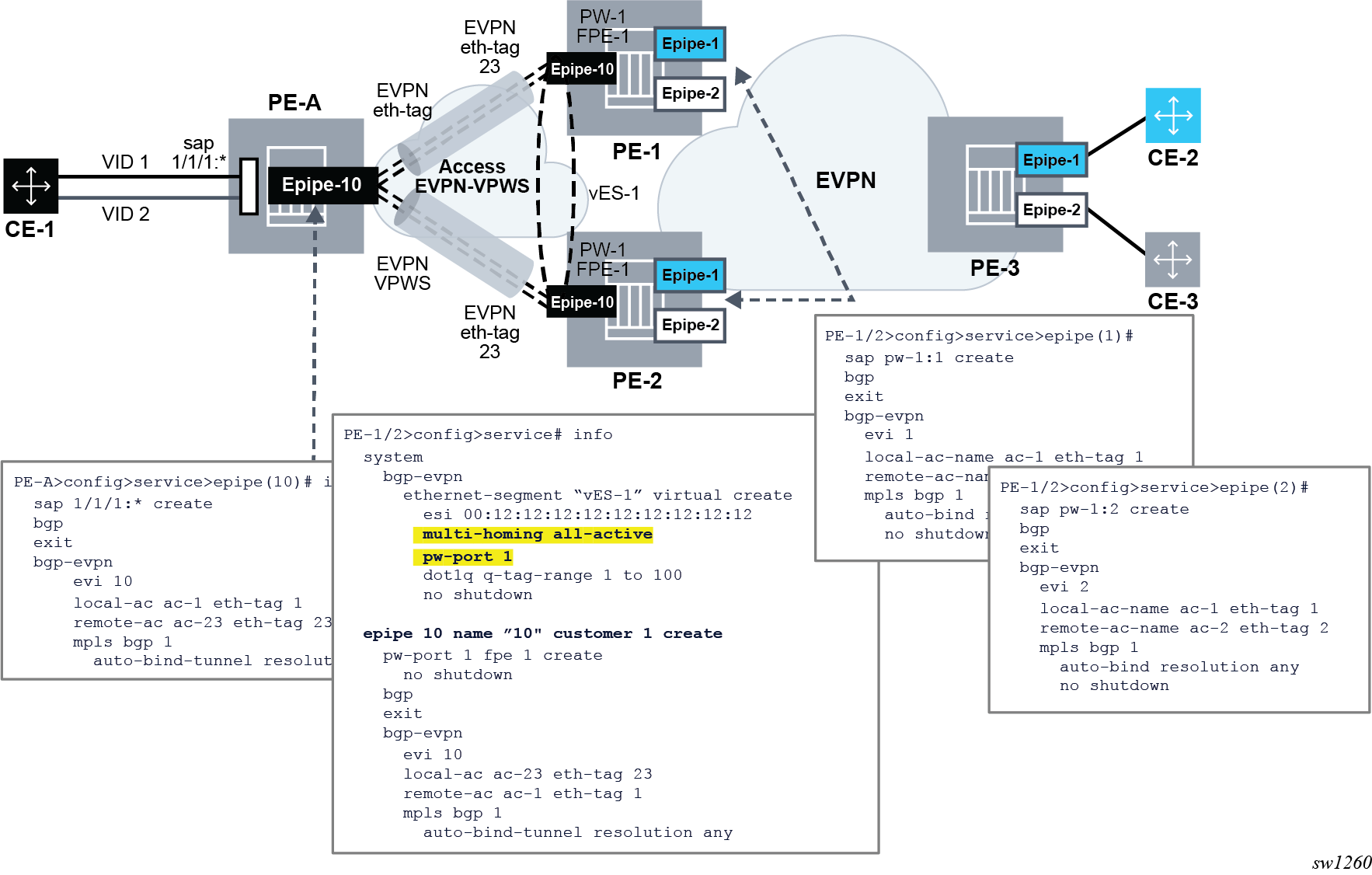
In this example, the following conditions apply:
- Redundancy is driven by EVPN all-active multihoming. ES-1 is a virtual ES configured on the FPE-based PW port on PE-1 and PE-2.
- The access network between the access PE (PE-A) and the network PEs (PE-1 and
PE-2), uses EVPN-VPWS to backhaul the traffic. Therefore, PE-1 and PE-2 use
EVPN-VPWS in the PW port stitching service, where:
- PE-1 and PE-2 apply the same Ethernet tag configuration on the stitching service (Epipe 10)
- Optionally PE-1 and PE-2 can use the same RD on the stitching service
- AD per-EVI routes for the stitching service Ethernet tags are advertised with ESI=0
- Forwarding in the CE-1 to CE-2 or CE-3 direction, works as follows:
- PE-A forwards traffic based on the selection of the best AD per-EVI route advertised by PE-1 and PE-2 for the stitching Epipe 10. This selection can be either BGP-based if PE-2 and PE-3 use the same RD in the stitching service, or EVPN-based if different RD is used.
- When the PE-1 route is selected, PE-1 receives the traffic on the local PW-SAP for Epipe 1 or Epipe 2, and forwards it based on the customer EVPN-VPWS rules in the core.
- Forwarding in the CE-2 or CE-3 to CE-1 direction, works as follows:
- PE-3 forwards the traffic based on the configuration of ECMP and aliasing rules for Epipe 1 and Epipe 2.
- PE-3 can send the traffic to PE-2 and PE-2 to PE-A, following different directions.
- If the user needs the traffic to follow a symmetric path in both directions, then the AD per-EVI route selection on PE-A and PE-3 can be handled so that the same PE (PE-1 or PE-2) is selected for both directions.
- For this example, the solution provides redundancy in case of node failures in
PE-1 or PE-2. However, the administrative shutdowns, configured in some objects,
are not propagated to PE-A, leading to traffic blackholing. As a result, black
holes may be caused by the following events in PE-1 or PE-2:
- Epipe 1 or Epipe 2 service shutdown
- Epipe 1 or Epipe 2 BGP-EVPN MPLS shutdown
- vES-1 shutdown
- BGP shutdown
PW port-based ESs with multihoming on stitching Epipe
The solution described in PW port-based ESs with multihoming procedures on PW SAPs provides PW-headend redundancy where the access PE selects one of the PW-headend PE devices based on BGP best path selection, and the traffic from the core to the access may follow an asymmetric path. This is because the multihoming procedures are actually run on the PW SAPs of the core services, and the AD per-EVI routes advertised in the context of the stitching Epipe use an ESI=0.
SR OS also supports a different mode of operation called pw-port headend which allows running the multihoming procedures in the stitching Epipe and, therefore, use regular EVPN-VPWS primary or backup signaling to the access PE. The mode of operation is supported in a single-active mode shown in the following figure.
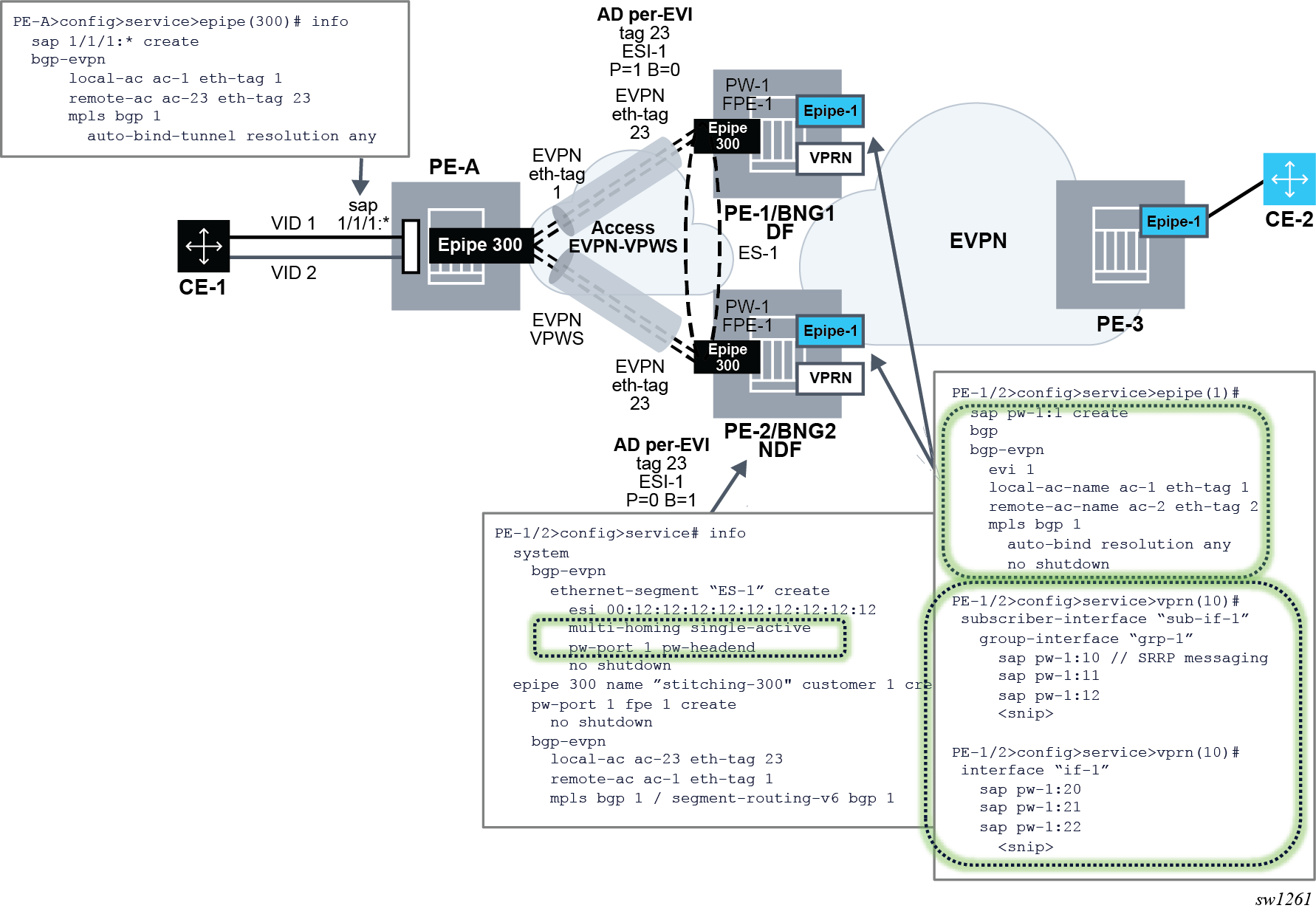
The following configuration triggers the needed behavior:
// ES and stitching Epipe config

PE-1/2>config>service# info
  system
    bgp-evpn
      ethernet-segment “ES-1” create
        esi 00:12:12:12:12:12:12:12:12:12
        multi-homing single-active
        pw-port 1 pw-headend
        no shutdown

  epipe 300 name ”stitching-300" customer 1 create
    pw-port 1 fpe 1 create
      no shutdown
    bgp-evpn
      local-attachment-circuit ac-23 eth-tag 23
      remote-attachment-circuit ac-1 eth-tag 1
      mpls bgp 1
        auto-bind-tunnel resolution any


// Services config

epipe 10
  sap pw-1:10 create
  bgp-evpn
    mpls bgp 1

epipe 11
  sap pw-1:10 create
  bgp-evpn
    mpls bgp 1
The configuration and functionality are divided in four aspects.
Configuration of single-active multihoming on ESs associated with PW ports of type pw-headend
In this mode, PW Ports are associated with single-active non-virtual Ethernet Segments. The pw-headend keyword is needed when associating the PW port.
PE-1/2>config>service# info
  system
    bgp-evpn
      ethernet-segment “ES-1” create
        esi 00:12:12:12:12:12:12:12:12:12
        multi-homing single-active
        pw-port 1 pw-headend
        no shutdown
The pw-port id pw-headend command indicates to the system that the multihoming procedures are run in the PW port stitching Epipe and the routes advertised in the context of the stitching Epipe contains the ESI of the ES.
Configuration of the PW port stitching Epipe
A configuration example of the stitching Epipe follows.
epipe 300 name ”stitching-300" customer 1 create
    pw-port 1 fpe 1 create
      no shutdown
    bgp-evpn
      local-attachment-circuit ac-23 eth-tag 23
      remote-attachment-circuit ac-1 eth-tag 1
      mpls bgp 1
        auto-bind-tunnel resolution any
The preceding example shows the configuration of a stitching EVPN VPWS Epipe with MPLS transport, however SRv6 transport is also supported.
When the ES is configured with a PW port in pw-headend mode, the stitching Epipe associated with the PW port is now running the ES and DF election procedures. Therefore, the following actions apply:
- an AD per-ES route is advertised with:
- the RD or RT of the stitching Epipe
- the configured ESI of the ES associated with the PW port
- the ESI-label extended community with the multihomed mode indication and ESI label
- an AD per EVI route is advertised with:
- the RD or RT of the stitching Epipe
- the configured ESI where the PW port resides
- the P/B bits according to the DF election procedures
- the non-DF drives the PW port operationally down with a flag MHStandby. As a result, all the PW SAPs contained in the PW port are brought operationally down. Optionally, the config>service>epipe>pw-port>oper-up-on-mhstandby command can be configured so that the PW port stays operationally up even if it is in MHStandby state (that is, the PE is non-DF). This command may speed up convergence in case a significant number of PW SAPs are configured in the same PW port.
Configuration of the PW port-contained PW SAPs and edge services
The edge services that contain the PW SAPs of the pw-headend pw-port command are configured without any other additional commands. These PW SAPs can be configured on Epipes, VPRN interfaces, or subscriber interfaces, VPLS (capture SAPs). As an example, if the PW SAP is configured on an Epipe EVPN-VPWS service:
epipe 10
  sap pw-1:10 create
  bgp-evpn
    mpls bgp 1
- The PW SAP is brought operationally down if the PW port is down. The PW port goes down with the reason MHStandby if the PE is a non-DF, or with reason stitching-svc-down if the EVPN destination is removed from the stitching Epipe.
- If the PW SAP is configured in an EVPN-VPWS edge service as in the preceding
example, the following actions are performed:
- An AD per ES route is advertised for the EVPN-VPWS service with the RD or RT of the service Epipe, the configured ESI of the ES associated with the PW port, and the ESI-label extended community with the multihomed mode indication of the ES and ESI label (label is the same value as in the AD per ES for the stitching Epipe). If the PW port is only down because of the MHStandby flag, the AD per ES route for the Epipe service is still advertised.
- In addition, an AD per EVI route is advertised with the RD or RT of
the service Epipe, the configured ESI of the ES associated with the
PW port, and the P/B flags of the ES:
- P=1/B=0 on the DF
- P=0/B=1 on backup
- P=0/B=0 on non-DFs and non-backup
- If the PW port is down only because of MHStandby, the AD per EVI route for the service Epipe is still advertised.
Some considerations and dependencies between the PW port and the service Epipe PW SAPs
- If all the PW SAPs associated with the FPE PW port are brought down, the
following rules apply:
- state of the PW port does not change
- does not trigger any AD per-ES/EVI or ES route withdraw toward the CE from the stitching Epipe
- Any event that brings down the PW port (except for MHStandby) triggers:
- an AD per-EVI/ES route withdrawal within the context of the stitching Epipe
- an ES route withdrawal
- an AD per-EVI/ES routes withdrawal within the context of the service Epipes
- the pw-port>monitoring-oper-group command can also modify the state of the PW port driven by the state of the operational group
- An individual PW SAP going administrative or operationally down while the PW
port is still operationally up, the following actions may be performed:
- may create black holes for that particular service
- triggers the withdrawal of the AD per-EVI routes for the service Epipe (not the AD per-ES route, which is kept advertised if the PW port is up)
- if the PW SAP is administratively not shutdown, the service Epipe AD per-ES/EVI routes mirror the AD per-ES/EVI routes of the stitching service and they are advertised if the routes for the stitching Epipe are advertised
The PW SAP can also be configured on VPRN services (under regular interfaces or subscriber interfaces) and works without any special consideration, other than that a PW port in non-DF state brings down the PW SAP and, therefore, the interface. Similarly, VPLS services with capture PW SAPs support this mode of operation too.
Interaction of EVPN and other features
This section describes the interaction of EVPN with other features.
Interaction of EVPN-MPLS with existing VPLS features
When enabling existing VPLS features in an EVPN-MPLS enabled service, the following considerations apply.
-
EVPN-MPLS is only supported in regular VPLS. Other VPLS types, such as m-vpls, are not supported with EVPN-MPLS.
In general, no router-generated control packets are sent to the EVPN destination bindings, except for proxy-ARP/proxy-ND confirm messages and Eth-CFM for EVPN-MPLS.
For xSTP and M-VPLS services:
xSTP can be configured in BGP-EVPN services. BPDUs are not sent over the EVPN bindings.
BGP-EVPN is blocked in M-VPLS services; however, a different M-VPLS service can manage a SAP or spoke-SDP in a BGP-EVPN-enabled service.
-
xSTP is not supported in BGP-EVPN services that use Ethernet segments for multihoming; an M-VPLS must not drive the state of a BGP-EVPN service that uses Ethernet segments.
For BGP-EVPN-enabled VPLS services, mac-move can be used in SAPs/SDP-bindings; however, the MACs being learned through BGP-EVPN are not considered.
Note: MAC duplication already provides a protection against MAC moves between EVPN and SAPs/SDP-bindings.The disable-learning command and other FDB-related tools work only for data plane learned MAC addresses.
The mac-protect command cannot be used in conjunction with EVPN.
Note: EVPN provides its own protection mechanism for static MAC addresses.MAC OAM tools (mac-ping, mac-trace, mac-populate, mac-purge, and cpe-ping) are not supported for BGP-EVPN services
EVPN multihoming and BGP-MH can be enabled in the same VPLS service, as long as they are not enabled in the same SAP-SDP or spoke-SDP. There is no limitation on the number of BGP-MH sites supported per EVPN-MPLS service.
SAPs/SDP-bindings that belong to a specified ES but are configured on non-BGP-EVPN-MPLS-enabled VPLS or Epipe services are kept down using the StandByForMHProtocol flag.
CPE ping is not supported on EVPN services but it is supported in PBB-EVPN services (including I-VPLS and PBB-Epipe). CPE ping packets are not sent over EVPN destinations.
Other features not supported in conjunction with BGP-EVPN:
subscriber management commands under service, SAP, and SDP-binding interfaces
BPDU translation
L2PT termination
MAC-pinning
Other features not supported in conjunction with the bgp-evpn mpls command are:
SPB configuration and attributes
Interaction of EVPN-MPLS with existing VPRN or IES features
When enabling existing VPRN features on interfaces linked to EVPN-MPLS R-VPLS interfaces, consider that the following are not supported:
the arp-populate and authentication-policy commands
dynamic routing protocols such as IS-IS, RIP, and OSPF
When enabling existing IES features on interfaces linked to EVPN-MPLS R-VPLS interfaces, the following commands are not supported:
if vpls evpn-tunnel
bgp-evpn ip-route-advertisement
arp-populate
authentication-policy
dynamic routing protocols such as IS-IS, RIP, and OSPF
Interaction of EVPN with BGP owners in the same VPRN service
SR OS allows multiple BGP owners in the same VPRN service to receive or advertise IP prefixes contained in the VPRN's route table. Specifically, the same VPRN route table can simultaneously install and process IPv4 or IPv6 prefixes for the following owners:
-
VPN-IP (also referred to as IPVPN routes)
-
IP (also referred to as BGP PE-CE routes)
The following figure shows the service architecture and the concept of different owners supported on the same VPRN.
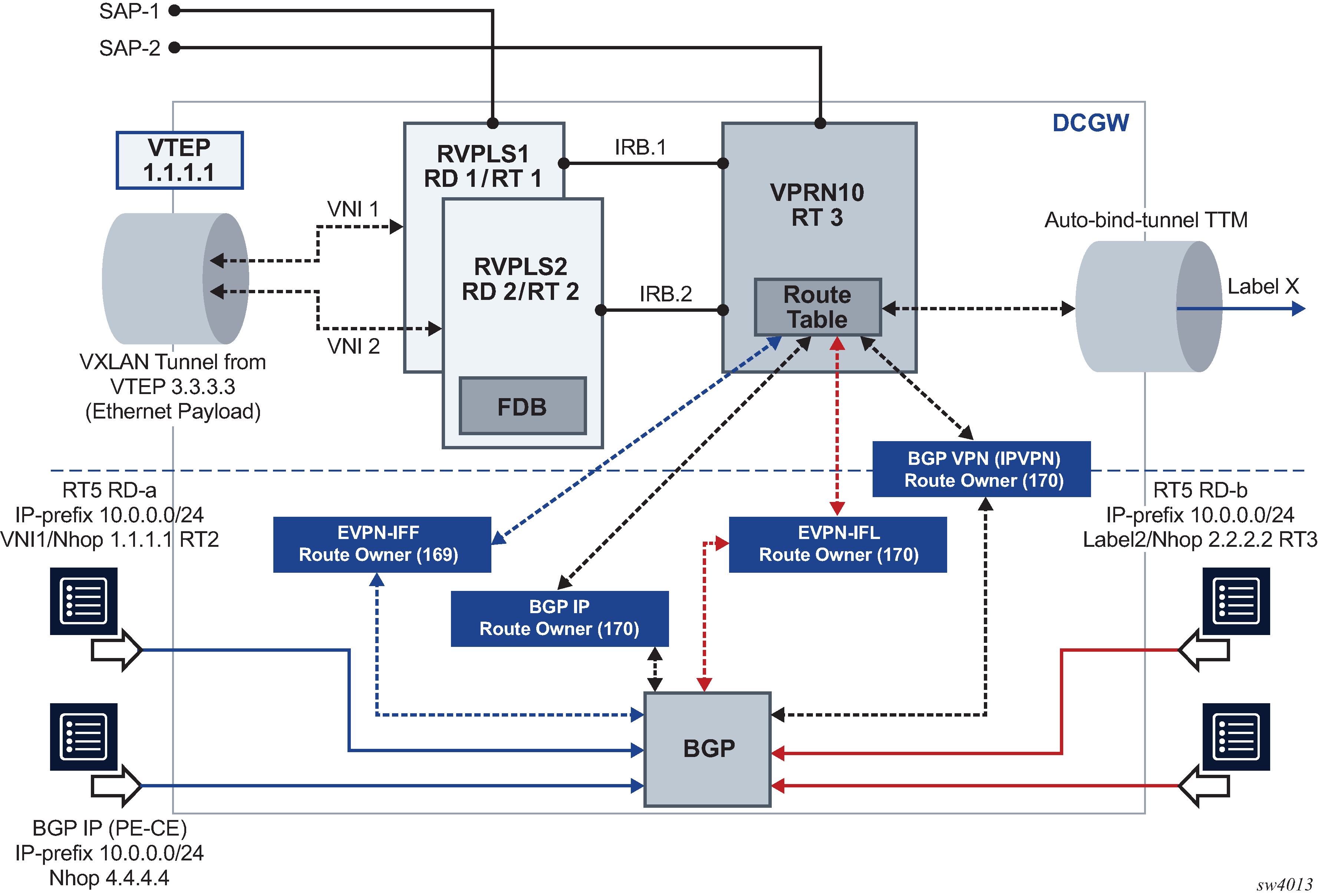
In the example shown in the preceding figure, VPRN 10 is configured with regular interfaces and R-VPLS interfaces and receives the same prefix 10.0.0.0/24 via the four owners.
EVPN-IFL routes are EVPN IP-Prefix (or type 5) routes that are imported and exported based on the VPRN bgp-evpn mpls configuration, as described in Interface-less IP-VRF-to-IP-VRF model (IP encapsulation) for MPLS tunnels.
EVPN-IFF routes are EVPN IP-Prefix (or type 5) routes that are imported and exported based on the configuration of the R-VPLS services attached to the VPRN. EVPN-IFF routes are advertised and processed if the R-VPLS services are configured with the configure service vpls bgp-evpn ip-route-advertisement command. Although installed in the VPRN service, EVPN-IFF routes use the route distinguisher and route targets determined by the configuration in the R-VPLS, and are supported in R-VPLS services with VXLAN or MPLS encapsulations. See Interface-ful IP-VRF-to-IP-VRF with SBD IRB model for more information about EVPN-IFF routes.
In addition to EVPN-IFL and EVPN-IFF routes, BGP IP and VPN-IP families are supported on the same VPRN.
BGP path attribute propagation
A VPRN can receive and install routes for a specific BGP for a specific BGP owner. The routes may be re-exported in the context of the same VPRN and to the same BGP owner or a different one. For example, an EVPN-IFL route can be received from peer N, installed in VPRN 1, and re-exported to peer M using family VPN-IPv4.
When re-exporting BGP routes, the original BGP path attributes are preserved without any configuration in the following cases:
-
EVPN-IFL or EVPN-IFL-HOST route re-exported into an IPVPN route, and an IPVPN route re-exported into an EVPN-IFL route
-
EVPN-IFL or EVPN-IFL-HOST route re-exported into a BGP IP route (PE-CE), and a BGP IP routes re-exported into an EVPN-IFL route
-
IPVPN route re-exported into a BGP IP route (PE-CE), and the other way around
-
EVPN-IFL or EVPN-IFL-HOST, IPVPN or BGP IP routes re-exported into a route of the same owner. For example, EVPN-IFL to EVPN-IFL, when the allow-export-bgp-vpn command is configured. Received EVPN-IFL-HOST routes are re-exported into an EVPN-IFL route when allow-export-bgp-vpn command is enabled.
Note: allow-export-bgp-vpn must never be used in a VPRN service with a route distinguisher that is used in other PEs attached to the same service. If the same route distinguisher is used in this case, constant route flaps occur.
BGP path attributes to or from EVPN-IFF are not preserved by default. If BGP Path Attribute propagation is required, the configure service system bgp-evpn ip-prefix-routes iff-attribute-uniform-propagation command must be configured. The following figure shows an example of BGP Path Attribute propagation from EVPN-IFF to the other BGP owners in the VPRN when the iff-attribute-uniform-propagation command is configured.
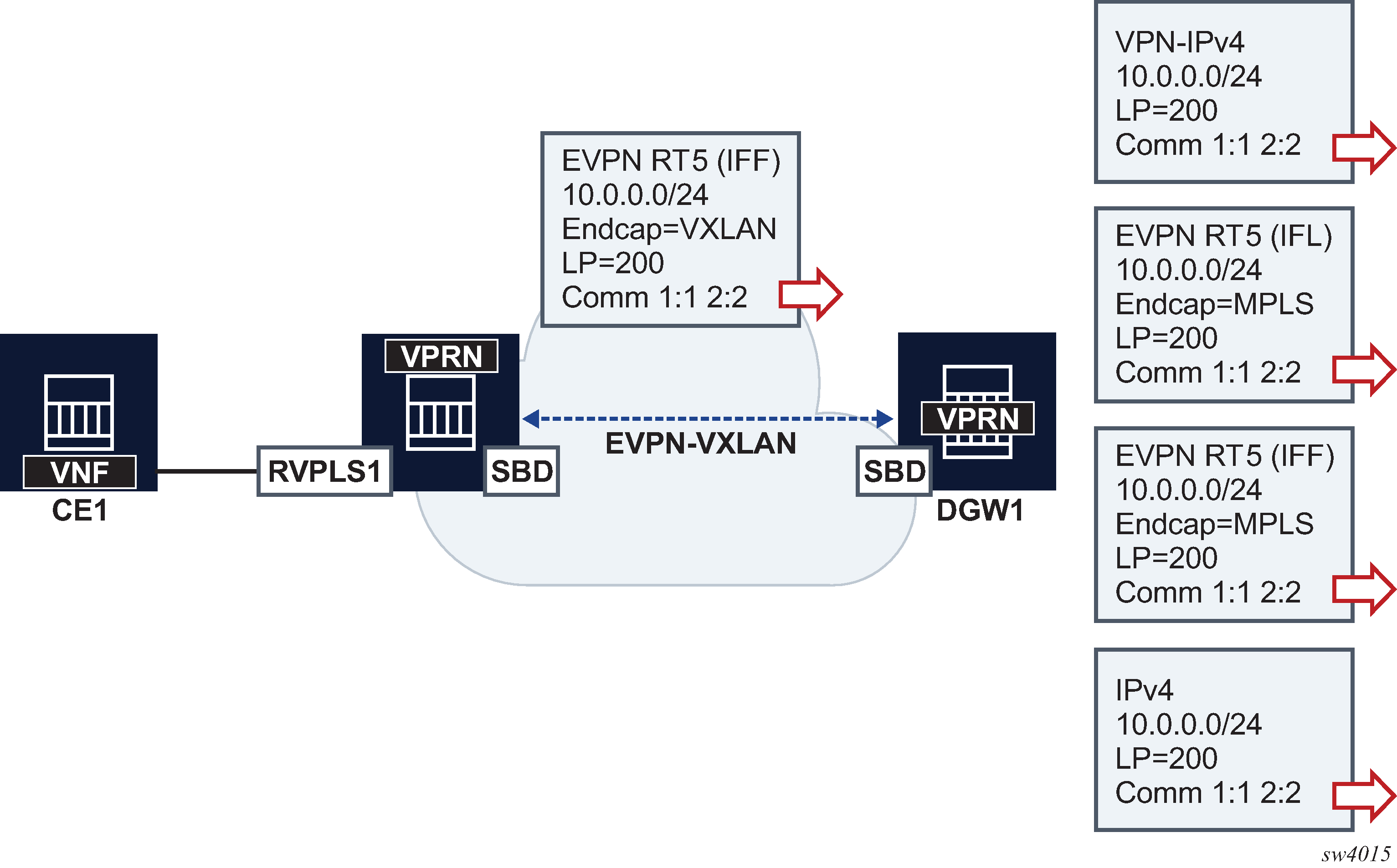
In the example in BGP path attribute propagation when iff-attribute-uniform-propagation is configured, DGW1 propagates the received LP and communities on an EVPN-IFF route, when advertising the same prefix into any type of BGP owner route, including VPN-IPv4/6, EVPN-IFL, EVPN-IFF, IPv4, or IPv6. If the iff-attribute-uniform-propagation command is not configured on DCW1, no BGP path attributes are propagated, but are re-originated instead. The propagation in the opposite direction follows the same rules; configuration of the iff-attribute-uniform-propagation command is required.
When propagating BGP path attributes, the following criteria are considered.
-
The propagation is compliant with the uniform propagation described in draft-ietf-bess-evpn-ipvpn-interworking.
-
The following extended communities are filtered or excluded when propagating attributes:
-
all extended communities of type 0x06 (EVPN type). In particular, all those that are supported by routes type 5:
-
MAC Mobility extended community (sub-type 0x00)
-
EVPN Router's MAC extended community (sub-type 0x03)
-
-
BGP encapsulation extended community
-
all Route Target extended communities
-
-
The BGP Path Attribute propagation within the same owner is supported in the following cases:
-
EVPN-IFF to EVPN-IFF (route received on R-VPLS and advertised in a different R-VPLS context), assuming the iff-attribute-uniform-propagation command is configured
-
EVPN-IFL or EVPN-IFL-HOST to EVPN-IFL (route received on a VPRN and re-advertised based on the configuration of vprn>allow-export-bgp-vpn)
-
VPN-IPv4/6 to VPN-IPv4/6 (route received on a VPRN and re-advertised based on the configuration of vprn>allow-export-bgp-vpn)
-
-
The propagation is supported for iBGP and eBGP as follows:
-
iBGP-only attributes can only be propagated to iBGP peers
-
non-transitive attributes are propagated based on existing rules
-
when peering an eBGP neighbor, the AS_PATH is prepended by the VPRN ASN
-
-
If ECMP is enabled in the VPRN and multiple routes of the same BGP owner with different Route Distinguishers are installed in the route table, only the BGP path attributes of the best route are subject for propagation.
BGP D-PATH attribute for Layer 3 loop protection
The SR OS has a full implementation of the D-PATH attribute as described in draft-ietf-bess-evpn-ipvpn-interworking.
D-PATH is composed of a sequence of domain segments (similar to AS_PATH). Each domain segment is graphically represented as shown in the following figure.
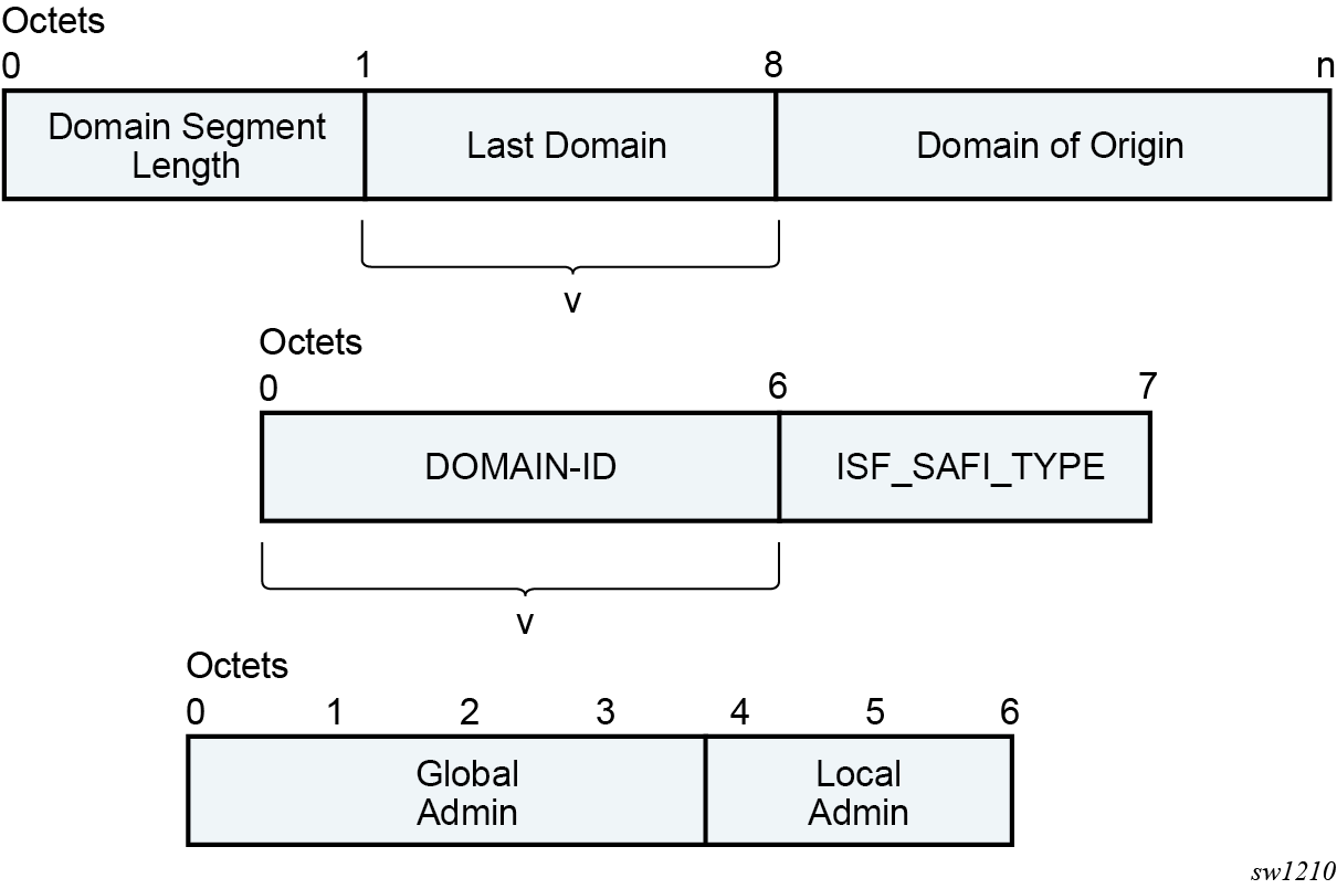
Where:
-
Each domain segment is comprised of <domain_segment_length, domain_segment_value>, where the domain segment value is a sequence of one or more domains.
-
Each domain is represented by <DOMAIN-ID:ISF_SAFI_TYPE>, where the newly added domain is added by a GW, is always prepended at the left of the existing last domain.
-
The supported ISF_SAFI_TYPE values are:
- 0 = Local ISF route
- 1 = safi 1 (typically identifies PE-CE BGP domains)
- 70 = evpn
- 128 = safi 128 (IPVPN domains)
-
Labeled unicast IP routes do not support D-PATH.
-
The D-PATH attribute is only modified by a gateway and not by an ABR/ASBR or RR. A gateway is defined as a PE where a VPRN is instantiated, and that VPRN advertises or receives routes from multiple BGP owners (for example, EVPN-IFL and BGP-IPVPN) or multiple instances of the same owner (for example, VPRN with two BGP-IPVPN instances
Suppose a router receives prefix P in an EVPN-IFL instance with the following D-PATH from neighbor N.
+----------+------------+
|Seg Len=1 | 65000:1:128|
+----------+------------+
If the router imports the route in VPRN-1, BGP-EVPN SRv6 instance with domain 65000:2, the router readvertises the route to its BGP-IPVPN MPLS instance as follows:
+----------+----------+-----------+
|Seg Len=2 |65000:2:70|65000:1:128|
+----------+----------+-----------+
If the router imports the route in VPRN-1, BGP-EVPN SRv6 instance with domain 65000:3, the router readvertises the route to its BGP-EVPN MPLS instance as follows:
+----------+----------+-----------+
|Seg Len=2 |65000:3:70|65000:1:128|
+----------+----------+-----------+
If the router imports the route in VPRN-1, BGP-EVPN MPLS instance with domain 65000:4, the router readvertises the route to its PE-CE BGP neighbor as follows:
+----------+----------+-----------+
|Seg Len=2 |65000:4:70|65000:1:128|
+----------+----------+-----------+
When a BGP route of families that support D-PATH is received and must be imported in a VPRN, the following rules apply:
-
All domain IDs included in the D-PATH are compared with the local domain IDs configured in the VPRN. The local domain IDs for the VPRN include a list of (up to four) domain IDs configured at the vprn or vprn bgp instance level, including the domain IDs in local attached R-VPLS instances.
-
If one or more D-PATH domain IDs match any local domain IDs for the VPRN, the route is not installed in the VPRN’s route table.
-
In the case where the IP-VPN or EVPN route matches the import route target in multiple VRFs, the D-PATH loop detection works per VPRN. For example, for each VPRN, BGP checks if the received domain IDs match any locally configured (maximum 4) domain IDs for that VPRN. A route may have a looped domain for one VPRN and not the other. In this case, BGP installs a route only in the VPRN route table that does not have a loop; the route is not installed in the VPRN that has the loop.
-
A route that is not installed in any VPRN RTM (due to the domain ID matching any of the local domain IDs in the importing VPRNs) is still kept in the RIB-IN. The route is displayed in the show router bgp routes command with a DPath Loop VRFs field, indicating the VPRN in which the route is not installed due to a loop.
-
Route target-based leaking between VPRNs and D-PATH loop detection is described in the following example.
Consider an EVPN-IFL or EVPN-IFL-HOST route to prefix P imported in VPRN 20 (configured with domain 65000:20) is leaked into VPRN 30.
When the route to prefix P is readvertised in the context of VPRN 30, which is enabled for BGP-IPVPN MPLS and BGP-EVPN MPLS, the readvertised BGP-IPVPN and BGP-EVPN routes have a D-PATH with a prepended domain 65000:20:0. That is, leaked routes are readvertised with the domain ID of the VPRN of origin and an ISF_SAFI_TYPE = 0, as described in draft-ietf-bess-evpn-ipvpn-interworking.
In the D-PATH example shown in the following figure, the different gateway PEs along the domains modify the D-PATH attribute by adding the source domain and family. If PE4 receives a route for the prefix with the domain of PE4 included in the D-PATH, PE4 does not install the route in order to avoid control plane loops.
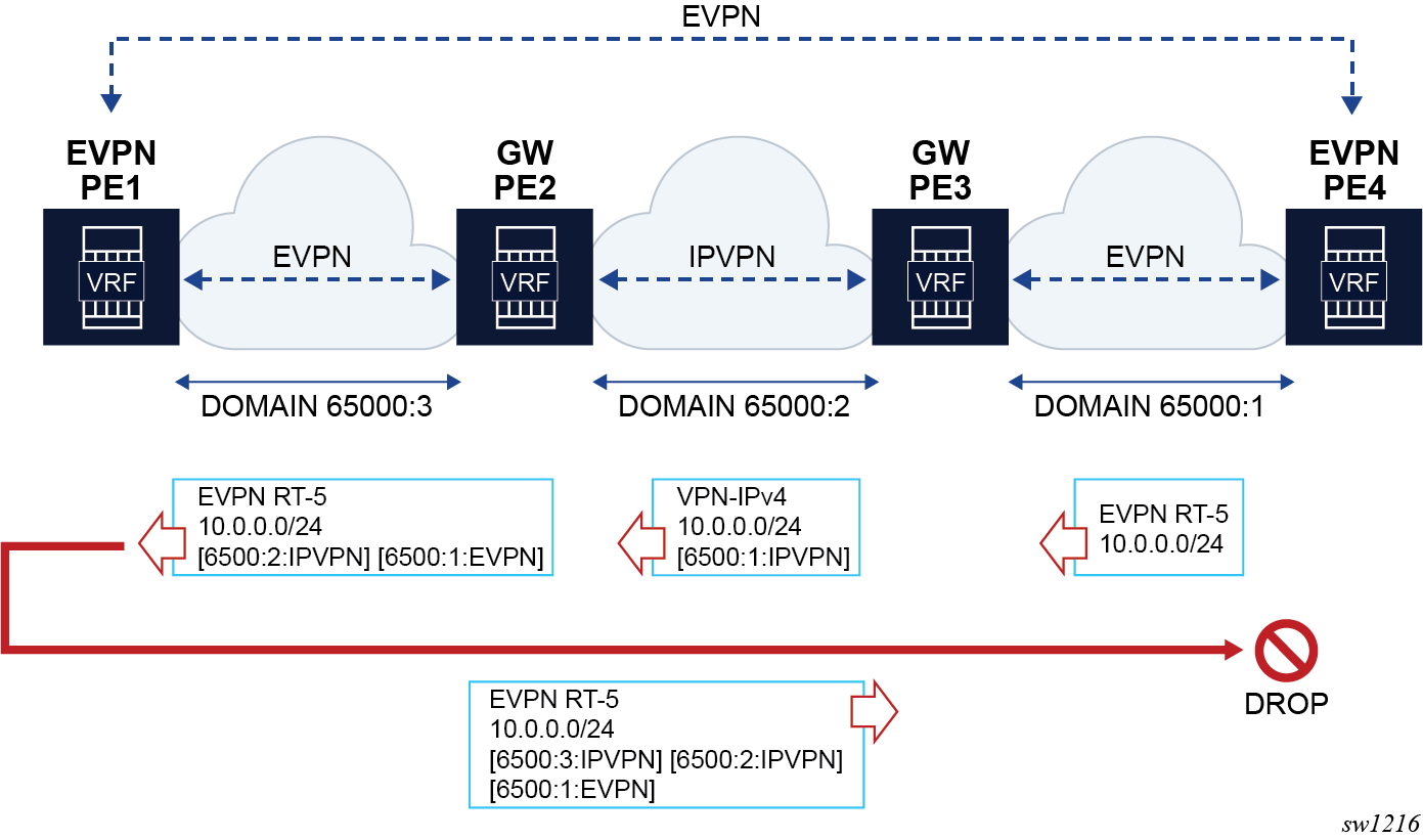
In the D-PATH example shown in the following figure, DGW1 and DGW2 rely on the D-PATH attribute to automatically discard the prefixes received from the peer gateway in IPVPN and avoid loops by reinjecting the route back into the EVPN domain.
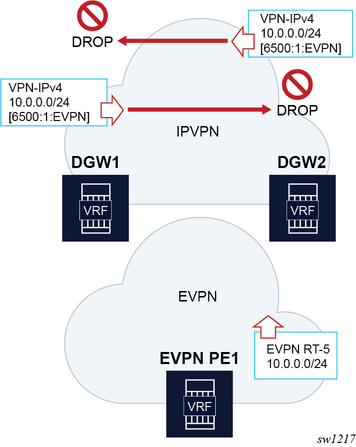
BGP D-PATH configuration
The D-PATH attribute is modified on transmission or processed on reception based on the local VPRN or R-VPLS configuration. The domain ID is configured per-BGP instance and the ISF_SAFI_TYPE automatically derived from the instance type that imported the original route.
The domain-id is configured at service bgp instance level as a six-byte value that includes a global admin value and a local admin value, for example, 65000:1. Domain ID configuration is supported on:
- VPRN BGP-EVPN MPLS and SRv6 instances (EVPN-IFL)
- VPRN BGP-IPVPN MPLS and SRv6 instance
- R-VPLS BGP-EVPN MPLS and VXLAN instances (EVPN-IFF only – the R-VPLS is configured with the evpn-tunnel command)
- VPRN BGP neighbors (PE-CE)
- VPRN level (for local routes)
The following is an example CLI configuration:
// domain-id configuration

*[ex:configure service vprn "blue" bgp-evpn mpls 1]
*[ex:configure service vprn "blue" bgp-evpn segment-routing-v6 1]
*[ex:configure service vprn "blue" bgp-ipvpn mpls 1]
*[ex:configure service vprn "blue" bgp-ipvpn segment-routing-v6 1]
*[ex:configure service vprn "blue" bgp]
*[ex:configure service vpls "blue" bgp-evpn routes ip-prefix]
+-- domain-id <global-field:local-field>


*[ex:configure service vprn "blue"]
A:admin@PE-2#
+-- local-routes-domain-id <global-field:local-field>
// used as the domain-id for non-bgp routes in the VPRN.


// Example ‘a’

*[ex:configure service vprn "blue" bgp-ipvpn mpls 1]
    domain-id 65000:1
In the preceding "example 'a'", if a VPN-IPv4 route is received from a neighbor, imported in VPRN "blue" and exported to another neighbor as EVPN, the router prepends a D-PATH segment <65000:1:IPVPN> to the advertised EVPN RT5.
// Example ‘b’

*[ex:configure service vprn "blue"]
    local-routes-domain-id 65000:10
In the preceding "example 'b'", the local-routes-domain-id is configured at the vprn level. When configured, local routes (direct, static, IGP routes) are advertised with a D-PATH that contains the vprn>local-routes-domain-id.
The following additional considerations apply:
- If vprn>local-routes-domain-id is not configured, the local routes are advertised into the BGP instances with no D-PATH.
- If a VPRN BGP instance is not configured with a domain ID, the following handling
applies.
- Routes imported in the VPRN BGP instance are readvertised in a different instance without modifying the D-PATH.
- Routes exported in the VPRN BGP instance are advertised with the D-PATH modified to include the domain ID of the instance that imported the route in the first place.
- Up to a maximum of four domain IDs per VPRN are supported. This includes domain IDs configured in the associated R-VPLS services.
- Modifying the domain IDs list initiates a route refresh for all address families associated with the VPRN.
BGP D-PATH and BGP best path selection
D-PATH is also considered for the BGP best path selection, as described in draft-ietf-bess-evpn-ipvpn-interworking.
As D-PATH is introduced in networks, not all the PEs may support D-PATH for BGP path selection. In order to guarantee compatibility in networks with PEs that do not support D-PATH the following command determines if the D-PATH should be considered for BGP best-path selection.
ex:/configure]
A:admin@PE-3#
router “Base” bgp best-path-selection d-path-length-ignore <boolean> // default: false
service vprn <string> bgp best-path-selection d-path-length-ignore <boolean> // default: false
service vprn <string> d-path-length-ignore <boolean> // default: false

configure service system bgp evpn ip-prefix-routes d-path-length-ignore <boolean> // default: false
The following conditions apply to the d-path-length-ignore command usage:
- When d-path-length-ignore is configured at the base router level (or vprn>bgp level for PE-CE routes), BGP ignores the D-PATH domain segment length for best path selection purposes. This ignores d-path-length when comparing two VPN routes or two IFL routes within the same RD. These VPN or IFL routes are processed in main BGP instance.
- When d-path-length-ignore is configured at the VPRN router level, the VPRN RTM ignores the D-PATH domain segment length for best path selection purposes (for routes in VPRN).
- When d-path-length-ignore is configured at the service system bgp evpn ip-prefix-routes context, EVPN ignores the D-PATH length when iff-bgp-path-selection is enabled.
- When d-path-length-ignore is not configured, the D-PATH length is considered in the BGP best path selection process (at the BGP, the RTM, and IFF levels, respectively).
Configuration examples
This section describes configuration examples for stitching IPVPN and EVPN-IFL domains and the propagation of BGP path attributes for EVPN-IFF.
Propagation of BGP path attributes for EVPN-IFF
In this configuration example, the DCGW PE2 re-exports EVPN-IFF routes into EVPN-IFF (leaked) routes and EVPN-IFL routes. The BGP path attributes are propagated as shown in Propagation of BGP path attributes for EVPN-IFF. As described in BGP path attribute propagation, EVPN extended communities, BGP encapsulation extended community and route targets are not propagated but instead, re-originated.
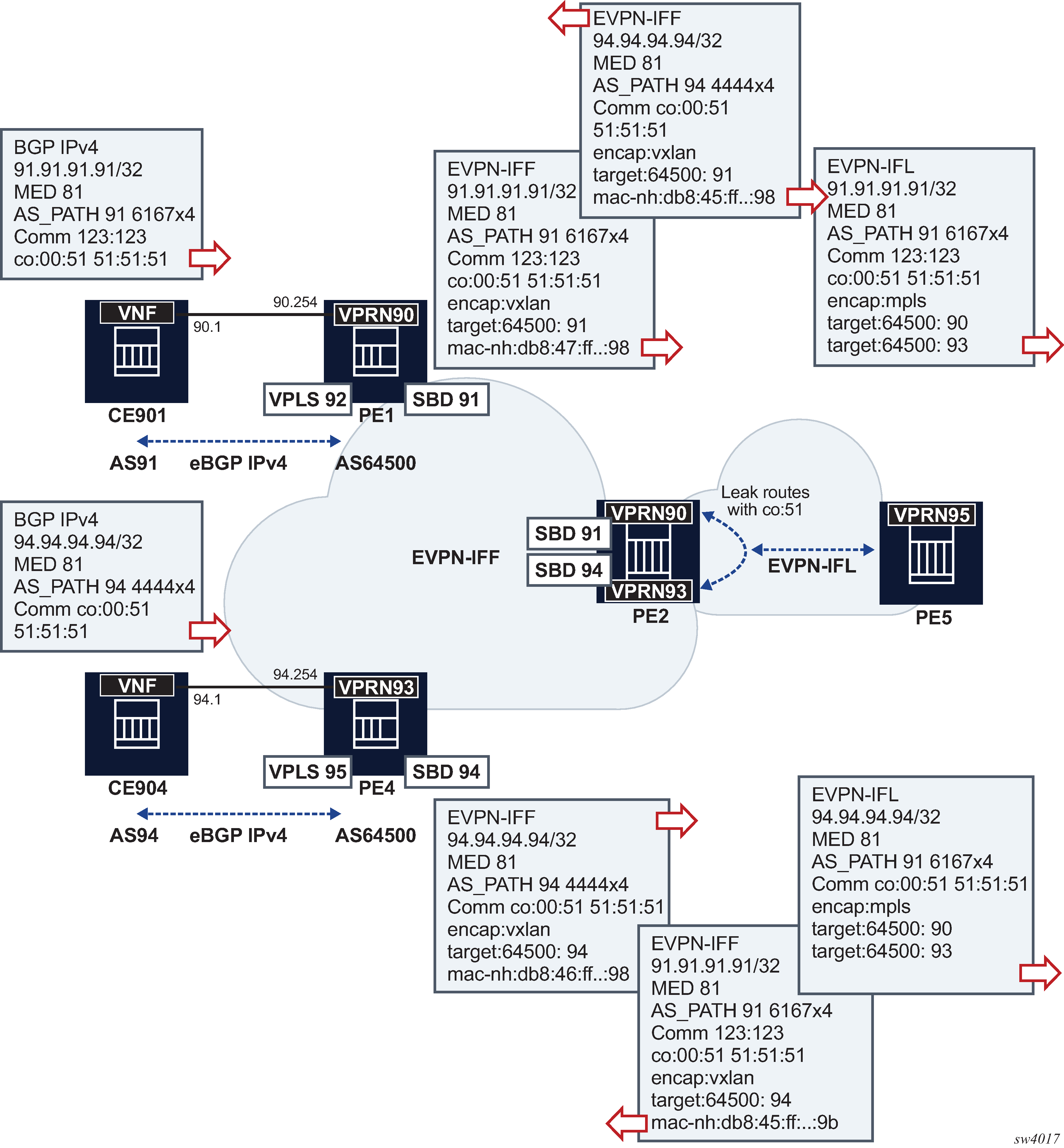
The following is an example configuration for PE4 and PE2 (PE1 has equivalent configuration as PE4).
// PE4 services for EVPN-IFF
A:PE-4>config>service>vprn# /configure service vprn 93
A:PE-4>config>service>vprn# info
----------------------------------------------
            router-id 4.4.4.4
            autonomous-system 64500
            interface "evi-95" create
                address 94.0.0.254/24
                vrrp 1 owner passive
                    backup 94.0.0.254
                exit
                vpls "evi-95"
                exit
            exit
            interface "evi-94" create
                vpls "evi-94"
                    evpn-tunnel
                exit
            exit
            bgp
                min-route-advertisement 1
                group "pe-ce"
                    family ipv4
                    type external
                    export "export-al-to-vnf"
                    neighbor 94.0.0.1
                        local-as 64500
                        peer-as 94
                    exit
                exit
                no shutdown
            exit
            no shutdown
----------------------------------------------
A:PE-4>config>service>vprn# /configure service vpls 95
A:PE-4>config>service>vpls# info
----------------------------------------------
            allow-ip-int-bind
            exit
            stp
                shutdown
            exit
            sap 1/1/c1/1:90 create
                no shutdown
            exit
            no shutdown
----------------------------------------------
A:PE-4>config>service>vpls# /configure service vpls 94
A:PE-4>config>service>vpls# info
----------------------------------------------
            allow-ip-int-bind
            exit
            vxlan instance 1 vni 94 create
            exit
            bgp
            exit
            bgp-evpn
                no mac-advertisement
                ip-route-advertisement
                evi 94
                vxlan bgp 1 vxlan-instance 1
                    no shutdown
                exit
            exit
            stp
                shutdown
            exit
            no shutdown
----------------------------------------------
// PE2 config
A:PE-2# configure service vprn 90
A:PE-2>config>service>vprn# info
----------------------------------------------
            interface "evi-91" create
                vpls "evi-91"
                    evpn-tunnel
                exit
            exit
            bgp-evpn
                mpls
                    auto-bind-tunnel
                        resolution any
                    exit
                    route-distinguisher 192.0.2.2:90
                    vrf-export "leak-color-51-into-93"
                    vrf-target import target:64500:90
                    no shutdown
                exit
            exit
            no shutdown
----------------------------------------------
A:PE-2>config>service>vprn# /configure service vpls 91
A:PE-2>config>service>vpls# info
----------------------------------------------
            allow-ip-int-bind
            exit
            vxlan instance 1 vni 91 create
            exit
            bgp
            exit
            bgp-evpn
                no mac-advertisement
                ip-route-advertisement
                evi 91
                vxlan bgp 1 vxlan-instance 1
                    no shutdown
                exit
            exit
            stp
                shutdown
            exit
            no shutdown
----------------------------------------------
A:PE-2>config>service>vpls# /configure service vprn 93
A:PE-2>config>service>vprn# info
----------------------------------------------
            interface "evi-94" create
                vpls "evi-94"
                    evpn-tunnel
                exit
            exit
            bgp-evpn
                mpls
                    auto-bind-tunnel
                        resolution any
                    exit
                    route-distinguisher 192.0.2.2:93
                    vrf-export "leak-color-51-into-90"
                    vrf-target import target:64500:93
                    no shutdown
                exit
            exit
            no shutdown
----------------------------------------------
A:PE-2>config>service>vprn# /configure service vpls 94
A:PE-2>config>service>vpls# info
----------------------------------------------
            allow-ip-int-bind
            exit
            vxlan instance 1 vni 94 create
            exit
            bgp
            exit
            bgp-evpn
                no mac-advertisement
                ip-route-advertisement
                evi 94
                vxlan bgp 1 vxlan-instance 1
                    no shutdown
                exit
            exit
            stp
                shutdown
            exit
            no shutdown
----------------------------------------------
A:PE-2>config>service>vpls# /show router policy "leak-color-51-into-90"
    entry 10
        from
            community "color-51"
        exit
        action accept
            community add "RT64500:90" "RT64500:93"
        exit
    exit
    default-action accept
        community add "RT64500:93"
    exit
A:PE-2>config>service>vpls# /show router policy "leak-color-51-into-93"
    entry 10
        from
            community "color-51"
        exit
        action accept
            community add "RT64500:90" "RT64500:93"
        exit
    exit
    default-action accept
        community add "RT64500:90"
    exit
D-PATH configuration
The example in the following figure shows a typical Layer 3 EVPN DC gateway scenario where EVPN-IFF routes are translated into IPVPN routes, and vice versa. Because redundant gateways are used, this scenario is subject to Layer 3 routing loops, and the D-PATH attribute helps preventing these loops in an automatic way, without the need for extra routing policies to tag or drop routes.
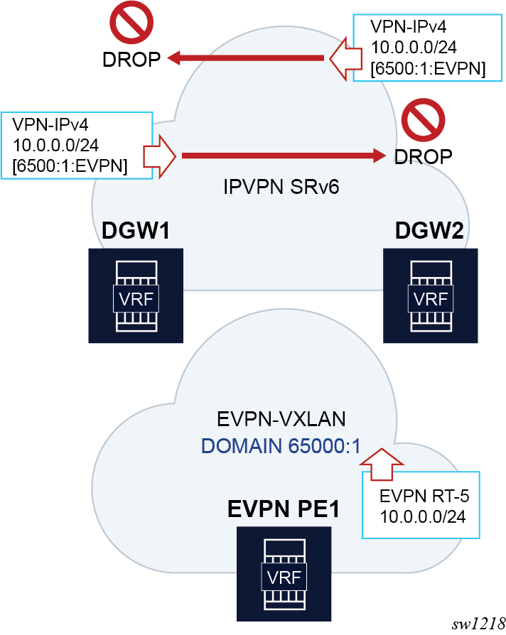
The following is the configuration of the VPRN or R-VPLS services in DGW1 and DGW2 in the preceding figure.
A:DGW1# configure service vprn 20
A:DGW1>config>service>vprn# info
----------------------------------------------
            interface "sbd-1" create
                vpls “sbd-1”
                    evpn-tunnel
                exit
            exit
            segment-routing-v6 1 create
                locator "LOC-1"
                    function
                        end-dt46
                    exit
                exit
            exit
            bgp-ipvpn
                segment-routing-v6
                    route-distinguisher 192.0.2.1:20
                    srv6-instance 1 default-locator "LOC-1"
                    source-address 2001:db8::1
                    vrf-target target:64500:20
                    domain-id 65000:2
                    no shutdown
                exit
            exit
            no shutdown
*A:DGW1# configure service vpls "sbd-1"
*A:DGW1>config>service>vpls# info
----------------------------------------------
            allow-ip-int-bind
            exit
            vxlan instance 1 vni 1 create
            exit
            bgp
            exit
            bgp-evpn
                evi 1
                ip-route-advertisement domain-id 65000:1
                vxlan bgp 1 vxlan-instance 1
                    no shutdown
                exit
            exit
            stp
                shutdown
            exit

A:DGW2# configure service vprn 20
A:DGW2>config>service>vprn# info
----------------------------------------------
            interface "sbd-1" create
                vpls “sbd-1”
                    evpn-tunnel
                exit
            exit
            segment-routing-v6 1 create
                locator "LOC-1"
                    function
                        end-dt46
                    exit
                exit
            exit
            bgp-ipvpn
                segment-routing-v6
                    route-distinguisher 192.0.2.2:20
                    srv6-instance 1 default-locator "LOC-1"
                    source-address 2001:db8::2
                    vrf-target target:64500:20
                    domain-id 65000:2
                    no shutdown
                exit
            exit
            no shutdown
*A:DGW2# configure service vpls "sbd-1"
*A:DGW2>config>service>vpls# info
----------------------------------------------
            allow-ip-int-bind
            exit
            vxlan instance 1 vni 1 create
            exit
            bgp
            exit
            bgp-evpn
                evi 1
                ip-route-advertisement domain-id 65000:1
                vxlan bgp 1 vxlan-instance 1
                    no shutdown
                exit
            exit
            stp
                shutdown
            exit
The following considerations apply to the example configuration shown in Use of D-PATH for Layer 3 DC gateway redundancy.
- Imported VPN-IP SRv6 routes are readvertised as EVPN-IFF VXLAN routes with a prepended D-PATH domain 65000:2:128.
- Imported EVPN-IFF VXLAN routes are readvertised as VPN-IP SRv6 routes with a prepended D-PATH domain 65000:1:70.
If PE1 sends an EVPN-IFF route 10.0.0.0/24 that is imported by both DGW1 and DGW2, then, when DGW1 and DGW2 receive each other’s routes, they identify the D-PATH attribute and compare the list of domains with the locally configured domains in the VPRN. Since the domain matches one of the local domains, the route is not installed in the VPRN route table and it is flagged as a looped route (the show router bgp routes detail or hunt commands show DPath Loop VRFs: 20). In this way loops are prevented.
Routing policies for BGP EVPN routes
Routing policies match on specific fields when importing or exporting EVPN routes. These matching fields (excluding route-table EVPN IP-prefix routes, unless explicitly mentioned), are:
communities (comm-val), extended communities (ext-comm), and large communities (large-comm)
well-known communities (well-known-comm); no-export | no-export-subconfed | no-advertise
family EVPN
protocol BGP-VPN (this term also matches VPN-IPv4 and VPN-IPv6 routes)
prefix lists for type 2 routes when they contain an IP address, and for type 5 routes
route tags that can be passed by EVPN to BGP from:
-
service>epipe/vpls>bgp-evpn>mpls/vxlan>default-route-tag (this route-tag can be matched on export only)
service>vpls>proxy-arp/nd>evpn-route-tag (this route tag can be matched on export only)
route-table route tags when exporting EVPN IP-prefix routes
-
EVPN type
BGP attributes that are applicable to EVPN routes (such as AS-path, local-preference, next-hop)
Additionally, the route tags can be used on export policies to match EVPN routes that belong to a service and BGP instance, routes that are created by the proxy-ARP/ND application, or IP-prefix routes that are added to the route-table with a route tag.
EVPN can pass only one route tag to BGP to achieve matching on export policies. In case of a conflict, the configured default-route-tag tag value has the least priority of the three potential tags added by EVPN.
For example, if VPLS 10 is configured with proxy-arp>evpn-route-tag 20 and bgp-evpn>mpls>default-route-tag 10, all MAC/IP routes that are generated by the proxy-ARP application use route tag 20. Export policies can then use ‟from tag 20” to match all those routes. In this case, inclusive Multicast routes are matched by using ‟from tag 10”.
Routing policies for BGP EVPN IP prefixes
BGP routing policies are supported for IP prefixes imported or exported through BGP-EVPN in R-VPLS services (EVPN-IFF routes) or VPRN services (EVPN-IFL routes).
When applying routing policies to control the distribution of prefixes between EVPN-IFF and IP-VPN (or EVPN-IFL), the user must consider that these owners are completely separate as far as BGP is concerned and when prefixes are imported in the VPRN routing table, the BGP attributes are lost to the other owner, unless the iff-attribute-uniform-propagation command is configured on the router.
If the iff-attribute-uniform-propagation command is disabled, the use of route tags allows the controlled distribution of prefixes across the two families.
The following figure shows an example of how VPN-IPv4 routes are imported into the RTM, and then passed to EVPN for its own process.

Policy tags can be used to match EVPN IP prefixes that were learned not only from BGP VPN-IPv4 but also from other routing protocols. The tag range supported for each protocol is different:
<tag>  : accepts in decimal or hex
        [0x1..0xFFFFFFFF]H (for OSPF and IS-IS)
        [0x1..0xFFFF]H (for RIP)
        [0x1..0xFF]H (for BGP)
The following figure shows an example of the reverse workflow: routes imported from EVPN and exported from RTM to BGP VPN-IPv4.

The preceding described behavior and the use of tags is also valid for VSI import and VSI export policies in the R-VPLS.
The following is a summary of the policy behavior for EVPN-IFF IP-prefixes when iff-attribute-uniform-propagation is disabled.
For EVPN-IFF routes received and imported in RTM, policy entries (peer or VSI-import) match on communities or any of the following fields, and can add tags (as action):
communities, extended-communities or large communities
well-known communities
family EVPN
protocol bgp-vpn
prefix-lists
EVPN route type
BGP attributes (as-path, local-preference, next-hop)
For exporting RTM to EVPN-IFF prefix routes, policy entries only match on tags, and based on this matching, add communities, accept, or reject. This applies to the peer level or on the VSI export level. Policy entries can also add tags for static routes, RIP, OSPF, IS-IS, BGP, and ARP-ND routes, which can then be matched on the BGP peer export policy, or on the VSI export policy for EVPN-IFF routes.
The following applies if the iff-attribute-uniform-propagation command is enabled.
For exporting RTM to EVPN-IFF prefix routes, in addition to matching on tags, matching path attributes on EVPN-IFF routes is supported in the following:
-
vrf-export (when exporting the prefixes in VPN-IP or EVPN IFL or IP routes)
-
vsi-export policies (when exporting the prefixes in EVPN-IFF routes)
-
for non-BGP route-owners (RIP, OSPF, IS-IS, static, ARP-ND), there are no changes and the only match criterion in vsi-export for EVPN-IFF routes is tags
EVPN Weighted ECMP for IP prefix routes
SR OS supports Weighted ECMP for EVPN IP Prefix routes (IPv4 and IPv6), in the EVPN Interface-less (EVPN-IFL) and EVPN Interface-ful (EVPN-IFF) models.
Based on draft-ietf-bess-evpn-unequal-lb, the EVPN Link Bandwidth extended community is used in the IP Prefix routes to indicate a weight that the receiver PE must consider when load balancing traffic to multiple EVPN, CE, or both next hops. The supported weight in the extended community is of type Generalized weight and encodes the count of CEs that advertised prefix N to a PE in a BGP PE-CE route. The following figure shows the use of EVPN Weighted ECMP.
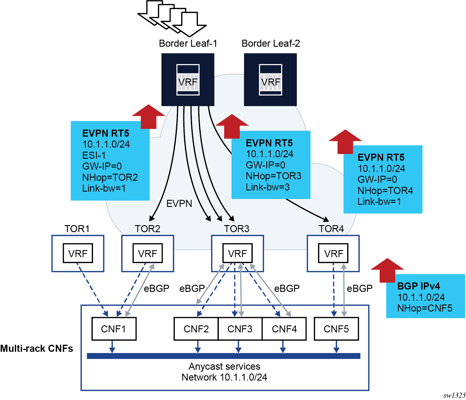
In the preceding figure, some multi-rack Container Network Functions (CNFs) are connected to a few TORs in the EVPN network. Each CNF advertises the same anycast service network 10.1.1.0/24 using a single PE-CE BGP session. Without Weighted ECMP, the TOR2, TOR3 and TO4 would re-advertise the prefix in an EVPN IP-Prefix route and flows to 10.1.1.0/24 from the Border Leaf-1 would be equally distributed among TOR2, TOR3 and TOR4. However, the needed load balancing distribution is based on the count of CNFs that are attached to each TOR. That is, out of five flows to 10.1.1.0/24, three should be directed to TOR3 (because it has three CNFs attached), one to TOR4 and one to either TOR2 or TOR1 (since CNF1 is dual-homed to both).
Weighted ECMP achieves the needed unequal load balancing based on the CNF count on each TOR. In the Weighted ECMP for IP Prefix routes use case example, if Weighted ECMP is enabled, the TORs add a weight encoded in the EVPN IP Prefix route, where the weight matches the count of CNFs that each TOR has locally . The Border Leaf creates an ECMP set for prefix 10.1.1.0/24 were the weights are considered when distributing the load to the prefix.
The procedures associated with EVPN Weighted ECMP for IP Prefix routes can be divided into advertising and receiving procedures:
- Use the following commands to configure the advertising procedures for EVPN IFL.Use the following command to configure the advertising procedures for EVPN IFF.
configure service vprn bgp-evpn mpls evpn-link-bandwidth advertise configure service vprn bgp-evpn segment-routing-v6 evpn-link-bandwidth advertiseconfigure service vpls bgp-evpn ip-route-link-bandwidth advertiseThe advertise command triggers the advertisement of the EVPN Link Bandwidth extended community with a weight that matches the CE count advertised by the route. The dynamic weight can, optionally, be overridden by a configuring the advertise weight value.
- Use the following commands to configure the receiving procedures for EVPN-IFL.Use the following command to configure the receiving procedures for EVPN-IFF.
configure service vprn bgp-evpn mpls evpn-link-bandwidth weighted-ecmp configure service vprn bgp-evpn segment-routing-v6 evpn-link-bandwidth weighted-ecmpconfigure service vpls bgp-evpn ip-route-link-bandwidth weighted-ecmpWhen the weighted-ecmp command is enabled, the receiving PE installs IP Prefix routes in the VPRN route-table associated with a normalized weight that is derived from the signaled weight.
- For EVPN-IFL, for weighted ECMP across EVPN next hops and CE next hops, the
following commands must be
configured.
configure service vprn bgp group evpn-link-bandwidth add-to-received-bgp configure service vprn bgp eibgp-loadbalance - For EVPN-IFF, Weighted ECMP can only be applied to EVPN next hops and not to the eibgp-loadbalance command.
- For EVPN-IFL, for weighted ECMP across EVPN next hops and CE next hops, the
following commands must be
configured.
EVPN-IFL MPLS service configuration
The following example shows the configuration of the EVPN Weighted ECMP feature for EVPN IFL routes with MPLS transport. A similar example could have been added for EVPN IFL routes with SRv6 transport.
Suppose PE2, PE4, and PE5 are attached to the same EVPN-IFL service on vprn 2000. PE4 is connected to two CEs (CE-41 and CE-42) and PE5 to one CE (CE-51). The three CEs advertise the same prefix 192.168.1.0/24 using PE-CE BGP and the goal is for PE2 to distribute to PE4 twice as many flows (to 192.168.1.0/24) as for PE5.
The configuration of PE4 and PE5 follows:
*A:PE-4# configure service vprn 2000
*A:PE-4>config>service>vprn# info
----------------------------------------------
ecmp 10
autonomous-system 64500
interface "to-CE41" create
address 10.41.0.1/24
sap pxc-3.a:401 create
exit
exit
interface "to-CE42" create
address 10.42.0.1/24
sap pxc-3.a:402 create
exit
exit
bgp-evpn
mpls
auto-bind-tunnel
resolution any
exit
evi 2000
evpn-link-bandwidth
advertise
weighted-ecmp
exit
route-distinguisher 192.0.2.4:2000
vrf-target target:64500:2000
no shutdown
exit
exit
bgp
multi-path
ipv4 10
exit
eibgp-loadbalance
router-id 4.4.4.4
rapid-withdrawal
group "pe-ce"
family ipv4 ipv6
neighbor 10.41.0.2
peer-as 64541
evpn-link-bandwidth
add-to-received-bgp 1
exit
exit
neighbor 10.42.0.2
peer-as 64542
evpn-link-bandwidth
add-to-received-bgp 1
exit
exit
exit
no shutdown
exit
no shutdown
A:PE-5# configure service vprn 2000
A:PE-5>config>service>vprn# info
----------------------------------------------
autonomous-system 64500
interface "to-CE51" create
address 10.51.0.1/24
sap pxc-3.a:501 create
exit
exit
bgp-evpn
mpls
auto-bind-tunnel
resolution any
exit
evi 2000
evpn-link-bandwidth
advertise
weighted-ecmp
exit
route-distinguisher 192.0.2.5:2000
vrf-target target:64500:2000
no shutdown
exit
exit
bgp
multi-path
ipv4 10
exit
eibgp-loadbalance
router-id 5.5.5.5
rapid-withdrawal
group "pe-ce"
family ipv4 ipv6
neighbor 10.51.0.2
peer-as 64551
evpn-link-bandwidth
add-to-received-bgp 1
exit
exit
exit
no shutdown
exit
no shutdown
The configuration on PE2 follows:
*A:PE-2# configure service vprn 2000
*A:PE-2>config>service>vprn# info
----------------------------------------------
ecmp 10
interface "to-PE" create
address 20.10.0.1/24
sap pxc-3.a:2000 create
exit
exit
bgp-evpn
mpls
auto-bind-tunnel
resolution any
exit
evi 2000
evpn-link-bandwidth
advertise
weighted-ecmp
exit
route-distinguisher 192.0.2.2:2000
vrf-target target:64500:2000
no shutdown
exit
exit
no shutdown
PE4 and PE5 IP Prefix route advertisement
As a result of the preceding configuration, PE4 (next-hop 2001:db8::4) and PE5 (next-hop 2001:db8::5) advertise the IP Prefix route from the CEs with weights 2 and 1 respectively:
*A:PE-2# show router bgp routes evpn ip-prefix prefix 192.168.1.0/24 community target:64500:2000 hunt
===============================================================================
BGP Router ID:192.0.2.2 AS:64500 Local AS:64500
===============================================================================
Legend -
Status codes : u - used, s - suppressed, h - history, d - decayed, * - valid
l - leaked, x - stale, > - best, b - backup, p - purge
Origin codes : i - IGP, e - EGP, ? - incomplete
===============================================================================
BGP EVPN IP-Prefix Routes
===============================================================================
-------------------------------------------------------------------------------
RIB In Entries
-------------------------------------------------------------------------------
Network : n/a
Nexthop : 2001:db8::4
Path Id : None
From : 2001:db8::4
Res. Nexthop : fe80::b446:ffff:fe00:142
Local Pref. : 100 Interface Name : int-PE-2-PE-4
Aggregator AS : None Aggregator : None
Atomic Aggr. : Not Atomic MED : None
AIGP Metric : None IGP Cost : 10
Connector : None
Community : target:64500:2000 evpn-bandwidth:1:2
bgp-tunnel-encap:MPLS
Cluster : No Cluster Members
Originator Id : None Peer Router Id : 192.0.2.4
Flags : Used Valid Best IGP
Route Source : Internal
AS-Path : 64541
EVPN type : IP-PREFIX
ESI : ESI-0
Tag : 0
Gateway Address: 00:00:00:00:00:00
Prefix : 192.168.1.0/24
Route Dist. : 192.0.2.4:2000
MPLS Label : LABEL 524283
Route Tag : 0
Neighbor-AS : 64541
Orig Validation: N/A
Source Class : 0 Dest Class : 0
Add Paths Send : Default
Last Modified : 01h19m43s
Network : n/a
Nexthop : 2001:db8::5
Path Id : None
From : 2001:db8::5
Res. Nexthop : fe80::b449:1ff:fe01:1f
Local Pref. : 100 Interface Name : int-PE-2-PE-5
Aggregator AS : None Aggregator : None
Atomic Aggr. : Not Atomic MED : None
AIGP Metric : None IGP Cost : 10
Connector : None
Community : target:64500:2000 evpn-bandwidth:1:1
bgp-tunnel-encap:MPLS
Cluster : No Cluster Members
Originator Id : None Peer Router Id : 192.0.2.5
Flags : Used Valid Best IGP
Route Source : Internal
AS-Path : 64551
EVPN type : IP-PREFIX
ESI : ESI-0
Tag : 0
Gateway Address: 00:00:00:00:00:00
Prefix : 192.168.1.0/24
Route Dist. : 192.0.2.5:2000
MPLS Label : LABEL 524285
Route Tag : 0
Neighbor-AS : 64551
Orig Validation: N/A
Source Class : 0 Dest Class : 0
Add Paths Send : Default
Last Modified : 00h08m45s
-------------------------------------------------------------------------------
RIB Out Entries
-------------------------------------------------------------------------------
-------------------------------------------------------------------------------
Routes : 2
===============================================================================
PE2 prefix installation
The show router id route-table extensive command performed on PE2, shows that PE2 installs the prefix with weights 2 and 1 respectively for PE4 and PE5:
*A:PE-2# show router 2000 route-table 192.168.1.0/24 extensive
===============================================================================
Route Table (Service: 2000)
===============================================================================
Dest Prefix : 192.168.1.0/24
Protocol : EVPN-IFL
Age : 01h22m47s
Preference : 170
Indirect Next-Hop : 2001:db8::4
Label : 524283
QoS : Priority=n/c, FC=n/c
Source-Class : 0
Dest-Class : 0
ECMP-Weight : 2
Resolving Next-Hop : 2001:db8::4 (LDP tunnel)
Metric : 10
ECMP-Weight : N/A
Indirect Next-Hop : 2001:db8::5
Label : 524285
QoS : Priority=n/c, FC=n/c
Source-Class : 0
Dest-Class : 0
ECMP-Weight : 1
Resolving Next-Hop : 2001:db8::5 (LDP tunnel)
Metric : 10
ECMP-Weight : N/A
-------------------------------------------------------------------------------
No. of Destinations: 1
===============================================================================
*A:PE-2# show router 2000 fib 1 192.168.1.0/24 extensive
===============================================================================
FIB Display (Service: 2000)
===============================================================================
Dest Prefix : 192.168.1.0/24
Protocol : EVPN-IFL
Installed : Y
Indirect Next-Hop : 2001:db8::4
Label : 524283
QoS : Priority=n/c, FC=n/c
Source-Class : 0
Dest-Class : 0
ECMP-Weight : 2
Resolving Next-Hop : 2001:db8::4 (LDP tunnel)
ECMP-Weight : 1
Indirect Next-Hop : 2001:db8::5
Label : 524285
QoS : Priority=n/c, FC=n/c
Source-Class : 0
Dest-Class : 0
ECMP-Weight : 1
Resolving Next-Hop : 2001:db8::5 (LDP tunnel)
ECMP-Weight : 1
===============================================================================
Total Entries : 1
===============================================================================
EVPN-IFL handling
In case of EVPN-IFL, Weighted ECMP is also supported for EIBGP load balancing among EVPN and CE next hops. For example, PE4 installs the same prefix with an EVPN-IFL next hop and two CE next hops, and each one with its normalized weight:
*A:PE-4# /show router 2000 route-table 192.168.1.0/24 extensive
===============================================================================
Route Table (Service: 2000)
===============================================================================
Dest Prefix : 192.168.1.0/24
Protocol : BGP
Age : 00h02m27s
Preference : 170
Indirect Next-Hop : 10.41.0.2
QoS : Priority=n/c, FC=n/c
Source-Class : 0
Dest-Class : 0
ECMP-Weight : 1
Resolving Next-Hop : 10.41.0.2
Interface : to-CE41
Metric : 0
ECMP-Weight : N/A
Indirect Next-Hop : 10.42.0.2
QoS : Priority=n/c, FC=n/c
Source-Class : 0
Dest-Class : 0
ECMP-Weight : 1
Resolving Next-Hop : 10.42.0.2
Interface : to-CE42
Metric : 0
ECMP-Weight : N/A
Indirect Next-Hop : 2001:db8::5
Label : 524285
QoS : Priority=n/c, FC=n/c
Source-Class : 0
Dest-Class : 0
ECMP-Weight : 1
Resolving Next-Hop : 2001:db8::5 (LDP tunnel)
Metric : 10
ECMP-Weight : N/A
-------------------------------------------------------------------------------
No. of Destinations: 1
===============================================================================
EVPN Sticky ECMP for IP prefix routes
SR OS supports sticky ECMP for EVPN-IFL and EVPN-IFF IP prefix routes. Non-sticky ECMP, or just ECMP, for a specific IP prefix with n number of next hops requires the router to rehash the flows when one of the next hops is removed or added. This may impact flows that are now sent to a different next hop.
- Upon withdrawal of one of the next hops, only the affected flows are redistributed into the remaining three next hops, as equally as possible.
- Upon addition of the fifth next hop, the router minimizes the impact on existing flows.
The implementation of sticky ECMP is based on software. The router emulates the behavior by repeating each ECMP next hop of the sticky route a number of times (according to the next-hop normalized weight) in different hash buckets, to create a fill pattern of size N for the incoming flows. In general, the closer the number of next hops gets to the maximum number of ECMP paths, the worse the distribution algorithm works. For detailed information about the general implementation of sticky ECMP in SR OS, see "BGP support for sticky ECMP" in the 7705 SAR Gen 2 Unicast Routing Protocols Guide.
An IP prefix is made sticky configuring the sticky-ecmp policy action on an import policy (at the peer or VPRN level). Sticky ECMP for EVPN IP-prefix routes is supported in combination with other ECMP features such as EVPN unequal ECMP or IP aliasing.
EVPN VLAN-aware bundle mode for BGP-EVPN VPLS or R-VPLS services
SR OS supports VLAN-aware bundle mode for BGP-EVPN VPLS or R-VPLS services, and is compliant with RFC 7432. A Broadcast Domain (BD) in RFC 7432 is mapped to a VPLS service in SR OS. Multiple BDs (VPLS services) can be grouped together under the same VLAN-aware bundle, where each BD is assigned a different Ethernet Tag ID.
Use the following command to associate a VPLS service with a bundle name.
configure service vpls bgp-evpn vlan-aware-bundleUse the following commands to indicate the Ethernet Tag ID allocated for the VPLS service within the bundle:
- MD-CLI
configure service vpls bgp-evpn routes vlan-aware-bundle-eth-tag - classic
CLI
configure service vpls bgp-evpn vlan-aware-bundle eth-tag
When the vlan-aware-bundle-eth-tag command is set to a non-zero value, the EVPN service routes (types 1, 2 and 3) advertised for the VPLS service are advertised with this value into the Ethernet Tag ID field of the routes. On reception of EVPN routes with non-zero Ethernet Tag ID, BGP imports the routes based on the import route target as usual. However, the system checks the received Ethernet Tag ID field and only processes routes whose Ethernet Tag ID match the local vlan-aware-bundle-eth-tag value. In addition, use commands in the following context to display details of the VPLS services in a given bundle.
show service vlan-aware-bundle The following example shows a configuration for VLAN-aware bundle, “bundle-1”. This bundle is composed of two services with Ethernet Tag IDs 120 and 121, respectively.
MD-CLI
[ex:/configure service]
A:admin@node-2# info
vpls "vpls-120-bundle-1" {
admin-state enable
service-id 120
customer "1"
routed-vpls {
}
bgp 1 {
}
bgp-evpn {
evi 120
vlan-aware-bundle "bundle-1"
routes {
vlan-aware-bundle-eth-tag 120
}
mpls 1 {
admin-state enable
ingress-replication-bum-label true
auto-bind-tunnel {
resolution any
}
}
}
sap pxc-10.a:120 {
}
}
vpls "vpls-121-bundle-1" {
admin-state enable
service-id 121
customer "1"
segment-routing-v6 1 {
locator "LOC-1" {
function {
end-dt2u {
}
end-dt2m {
}
}
}
}
bgp 1 {
route-target {
export "target:64500:120"
import "target:64500:120"
}
}
bgp-evpn {
evi 121
vlan-aware-bundle "bundle-1"
routes {
vlan-aware-bundle-eth-tag 121
}
segment-routing-v6 1 {
admin-state enable
source-address 2001:db8::2
srv6 {
instance 1
default-locator "LOC-1"
}
}
}
}
classic CLI
A:node-2>config>service# info
----------------------------------------------
vpls 120 name "vpls-120-bundle-1" customer 1 create
allow-ip-int-bind
exit
bgp
exit
bgp-evpn
vlan-aware-bundle "bundle-1" eth-tag 120
evi 120
mpls bgp 1
ingress-replication-bum-label
auto-bind-tunnel
resolution any
exit
no shutdown
exit
exit
stp
shutdown
exit
sap pxc-10.a:120 create
no shutdown
exit
no shutdown
exit
vpls 121 name "vpls-121-bundle-1" customer 1 create
segment-routing-v6 1 create
locator "LOC-1"
function
end-dt2u
end-dt2m
exit
exit
exit
bgp
route-target export target:64500:120 import target:64500:120
exit
bgp-evpn
vlan-aware-bundle "bundle-1" eth-tag 121
evi 121
segment-routing-v6 bgp 1 srv6-instance 1 default-locator "LOC-1" create
source-address 2001:db8::2
no shutdown
exit
exit
stp
shutdown
exit
no shutdown
exit
# show service vlan-aware-bundle ================================================================
VLAN Aware Bundle
================================================================
Bundle Service Id Eth Tag Evi
----------------------------------------------------------------
bundle-1 120 120 120
121 121 121
----------------------------------------------------------------
Number of entries: 2
----------------------------------------------------------------
================================================================
===============================================================================
VLAN Aware Bundle Summary
===============================================================================
MAC Entries : 2
EVPN-MPLS Destinations : 2
EVPN-MPLS Ethernet Segment Destinations: 0
VXLAN Destinations : 0
VXLAN Ethernet Segment Destinations : 0
SRv6 Destinations : 2
SRv6 Ethernet segment Destinations : 0
===============================================================================
# show service vlan-aware-bundle "bundle-1" fdb ===============================================================================
Service Id: 120 Name: vpls-120-bundle-1
===============================================================================
Forwarding Database, Service 120
===============================================================================
ServId MAC Source-Identifier Type Last Change
Transport:Tnl-Id Age
-------------------------------------------------------------------------------
120 00:ca:fe:ca:fe:01 mpls-1: EvpnS:P 01/22/24 14:33:31
192.0.2.5:524270
ldp:65543
-------------------------------------------------------------------------------
No. of MAC Entries: 1
-------------------------------------------------------------------------------
Legend:L=Learned O=Oam P=Protected-MAC C=Conditional S=Static Lf=Leaf T=Trusted
===============================================================================
===============================================================================
Service Id: 121 Name: vpls-121-bundle-1
===============================================================================
Forwarding Database, Service 121
===============================================================================
ServId MAC Source-Identifier Type Last Change
Transport:Tnl-Id Age
-------------------------------------------------------------------------------
121 00:ca:fe:ca:fe:01 srv6-1: EvpnS:P 01/22/24 14:33:39
192.0.2.5
cafe:1:0:5:7b1c:d000::
-------------------------------------------------------------------------------
No. of MAC Entries: 1
-------------------------------------------------------------------------------
Legend:L=Learned O=Oam P=Protected-MAC C=Conditional S=Static Lf=Leaf T=Trusted
===============================================================================
Configuring an EVPN service with CLI
This section provides information to configure VPLS using the command line interface.
EVPN-MPLS configuration examples
This section provides EVPN-MPLS configuration examples.
EVPN all-active multihoming example
This section shows a configuration example for three 7705 SAR Gen 2 PEs, all the following assumptions are considered:
-
PE-1 and PE-2 are multihomed to CE-12 that uses a LAG to get connected to the network. CE-12 is connected to LAG SAPs configured with all-active multihoming.
-
PE-3 is a remote PE that performs aliasing for traffic destined for the CE-12
Configuration output of VPLS-1 on PE-1 and PE-2
The following configuration example applies to a VPLS-1 on PE-1 and PE-2, as well as the corresponding lag commands.
A:PE1# configure lag 1
A:PE1>config>lag# info
----------------------------------------------
mode access
encap-type dot1q
port 1/1/2
lacp active administrative-key 1 system-id 00:00:00:00:69:72
no shutdown
----------------------------------------------
A:PE1>config>lag# /configure service system bgp-evpn
A:PE1>config>service>system>bgp-evpn# info
----------------------------------------------
route-distinguisher 192.0.2.69:0
exit
----------------------------------------------
A:PE1>config>service>system>bgp-evpn# /configure service vpls 1
A:PE1>config>service>vpls# info
----------------------------------------------
bgp
exit
bgp-evpn
cfm-mac-advertisement
evi 1
vxlan
shutdown
exit
mpls bgp 1
ingress-replication-bum-label
auto-bind-tunnel
resolution any
exit
no shutdown
exit
exit
stp
shutdown
exit
sap lag-1:1 create
exit
no shutdown
----------------------------------------------
A:PE2# configure lag 1
A:PE2>config>lag# info
----------------------------------------------
mode access
encap-type dot1q
port 1/1/3
lacp active administrative-key 1 system-id 00:00:00:00:69:72
no shutdown
----------------------------------------------
A:PE2>config>lag# configure service vpls 1
A:PE2>config>service>vpls# info
----------------------------------------------
bgp
exit
bgp-evpn
cfm-mac-advertisement
evi 1
vxlan
shutdown
exit
mpls bgp 1
ingress-replication-bum-label
auto-bind-tunnel
resolution any
exit
no shutdown
exit
exit
stp
shutdown
exit
sap lag-1:1 create
exit
no shutdown
----------------------------------------------
Configuration on the remote PE
The following example shows the configuration on the remote PE (for example, PE-3), which supports aliasing to PE-1 and PE-2. PE-3 only requires the VPLS-1 configuration and ecmp>1 to perform aliasing.
*A:PE3>config>service>vpls# info
----------------------------------------------
bgp
exit
bgp-evpn
cfm-mac-advertisement
evi 1
mpls bgp 1
ingress-replication-bum-label
ecmp 4
auto-bind-tunnel
resolution any
exit
no shutdown
exit
exit
stp
shutdown
exit
sap 1/1/1:1 create
exit
spoke-sdp 4:13 create
no shutdown
exit
no shutdown
----------------------------------------------
EVPN single-active multihoming example
To use single-active multihoming on PE-1 and PE-2 instead of all-active multihoming:
-
change the LAG configuration to multi-homing single-active
The CE-12 is now configured with two different LAGs; therefore the key, system ID, and system priority values must be different on PE-1 and PE-2
No changes are needed at the service level on any of the three PEs.
A:PE1# configure lag 1
A:PE1>config>lag# info
----------------------------------------------
mode access
encap-type dot1q
port 1/1/2
lacp active administrative-key 1 system-id 00:00:00:00:69:69
no shutdown
----------------------------------------------
A:PE1>config>lag# /configure service system bgp-evpn
A:PE1>config>service>system>bgp-evpn# info
----------------------------------------------
route-distinguisher 192.0.2.69:0
exit
----------------------------------------------
A:PE2# configure lag 1
A:PE2>config>lag# info
----------------------------------------------
mode access
encap-type dot1q
port 1/1/3
lacp active administrative-key 1 system-id 00:00:00:00:72:72
no shutdown
----------------------------------------------
A:PE2>config>lag# /configure service system bgp-evpn
A:PE2>config>service>system>bgp-evpn# info
----------------------------------------------
route-distinguisher 192.0.2.72:0
exit
----------------------------------------------