VLL services
This chapter provides information about Virtual Leased Line (VLL) services and implementation notes.
Ethernet pipe service
This section provides information about the Ethernet pipe (Epipe) service and implementation notes.
Epipe service overview
An Epipe service is the Nokia implementation of an Ethernet VLL based on the IETF "Martini Drafts" (draft-martini-l2circuit-trans-mpls-08.txt and draft-martini-l2circuit-encapmpls-04.txt) and the IETF Ethernet Pseudowire Draft (draft-so-pwe3-ethernet-00.txt).
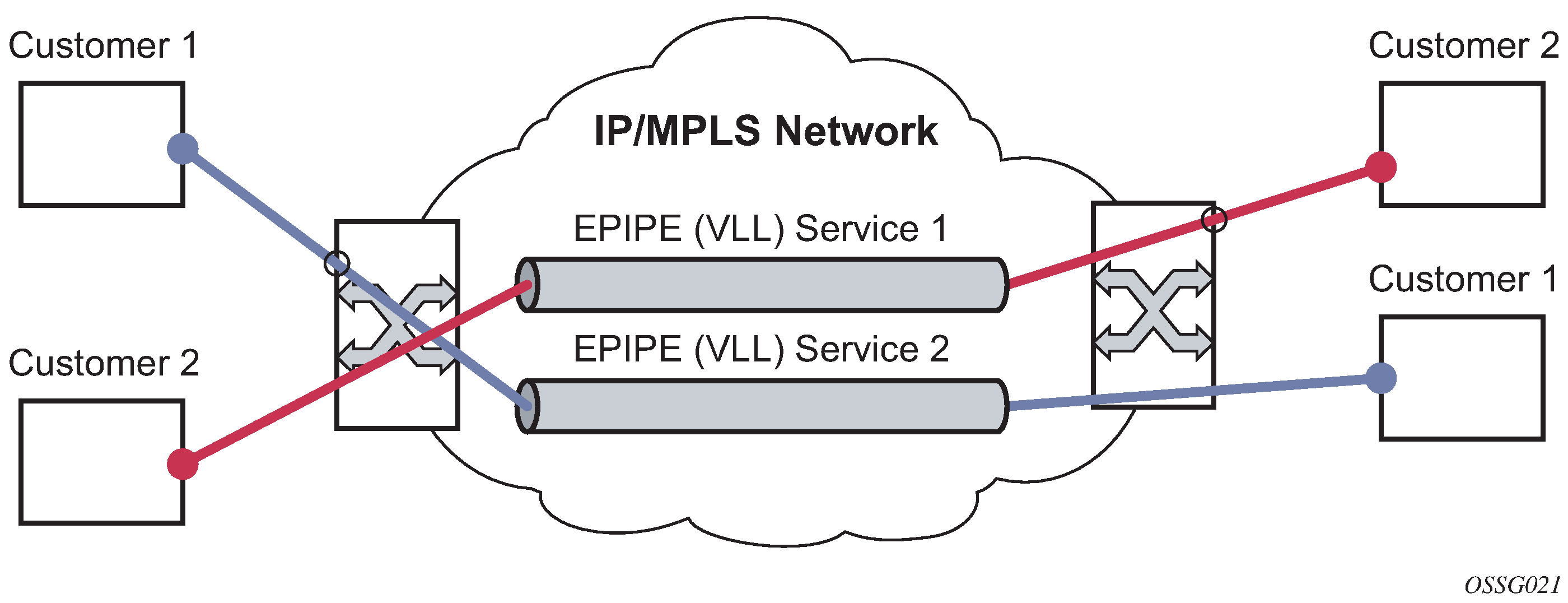
An Epipe service is a Layer 2 point-to-point service where the customer data is encapsulated and transported across a service provider IP, MPLS, or Provider Backbone Bridging (PBB) VPLS network. An Epipe service is completely transparent to the customer data and protocols. The Epipe service does not perform any MAC learning. A local Epipe service consists of two SAPs on the same node, whereas a distributed Epipe service consists of two SAPs on different nodes. SDPs are not used in local Epipe services.
Each SAP configuration includes a specific port or channel on which service traffic enters the router from the customer side (also called the access side). Each port is configured with an encapsulation type. If a port is configured with an IEEE 802.1Q (referred to as dot1q) encapsulation, a unique encapsulation value (ID) must be specified.
Epipe service pseudowire VLAN tag processing
Distributed Epipe services are connected using a pseudowire, which can be provisioned statically or dynamically and is represented in the system as a spoke-SDP. The spoke-SDP can be configured to process zero, one, or two VLAN tags as traffic is transmitted and received; see Epipe spoke-SDP VLAN tag processing: ingress and Epipe-spoke SDP VLAN tag processing: egress for the ingress and egress tag processing. In the transmit direction, VLAN tags are added to the frame being sent. In the received direction, VLAN tags are removed from the frame being received. This is analogous to the SAP operations on a null, dot1q, and QinQ SAP.
The system expects a symmetrical configuration with its peer; specifically, it expects to remove the same number of VLAN tags from received traffic as it adds to transmitted traffic. When removing VLAN tags from a spoke-SDP, the system attempts to remove the configured number of VLAN tags. If fewer tags are found, the system removes the VLAN tags found and forwards the resulting packet.
Because some of the related configuration parameters are local and not communicated in the signaling plane, an asymmetrical behavior cannot always be detected and so cannot be blocked. With an asymmetrical behavior, a protocol extraction does not necessarily function as it would with a symmetrical configuration, resulting in an unexpected operation.
The VLAN tag processing is configured as follows on a spoke-SDP in an Epipe service:
zero VLAN tags processed
This requires the configuration of vc-type ether under the spoke-SDP, or in the related PW template.
one VLAN tag processed
This requires one of the following configurations:
vc-type vlan under the spoke-SDP or in the related PW template
vc-type ether and force-vlan-vc-forwarding under the spoke-SDP or in the related PW template
two VLAN tags processed
This requires the configuration of force-qinq-vc-forwarding [c-tag-c-tag | s-tag-c-tag] under the spoke-SDP or in the related PW template.
The PW template configuration provides support for BGP VPWS services.
The following restrictions apply to VLAN tag processing:
The configuration of vc-type vlan and force-vlan-vc-forwarding is mutually exclusive.
force-qinq-vc-forwarding [c-tag-c-tag | s-tag-c-tag] can be configured with the spoke-SDP signaled as either vc-type ether or vc-type vlan.
The following are not supported with force-qinq-vc-forwarding [c-tag-c-tag | s-tag-c-tag] configured under the spoke-SDP, or in the related PW template:
Multisegment pseudowires.
PBB-Epipe services
force-vlan-vc-forwarding under the same spoke-SDP or PW template
Eth-CFM LM tests are NOT supported on UP MEPs when force-qinq-vc-forwarding is enabled.
Epipe spoke-SDP VLAN tag processing: ingress and Epipe-spoke SDP VLAN tag processing: egress describe the VLAN tag processing with respect to the zero, one, and two VLAN tag configuration described for the VLAN identifiers, Ethertype, ingress QoS classification (dot1p or DE), and QoS propagation to the egress (which can be used for egress classification or to set the QoS information, or both, in the innermost egress VLAN tag).
| Ingress (received on spoke-SDP) | Zero VLAN tags | One VLAN tag | Two VLAN tags (enabled by force-qinq-vc-forwarding [c-tag-c-tag | s-tag-c-tag] |
|---|---|---|---|
VLAN identifiers |
— |
Ignored |
Both inner and outer ignored |
Ethertype (to determine the presence of a VLAN tag) |
N/A |
0x8100 or value configured under sdp vlan-vc-etype |
Both inner and outer VLAN tags: 0x8100, or outer VLAN tag value configured under sdp vlan-vc-etype (inner VLAN tag value must be 0x8100) |
Ingress QoS (dot1p/DE) classification |
— |
Ignored |
Both inner and outer ignored |
QoS (dot1p/DE) propagation to egress |
Dot1p/DE=0 |
Dot1p/DE taken from received VLAN tag |
Dot1p/DE taken as follows:
The egress cannot be a spoke-sdp because force-qinq-vc-forwarding does not support multisegment PWs. |
| Egress (sent on mesh or spoke-SDP) | Zero VLAN tags | One VLAN tag | Two VLAN tags (enabled by force-qinq-vc-forwarding [c-tag-c-tag | s-tag-c-tag] |
|---|---|---|---|
VLAN identifiers (set in VLAN tags) |
— |
The tag is derived from one of the following:
|
The inner and outer VLAN tags are derived from one of the following:
|
Ethertype (set in VLAN tags) |
— |
0x8100 or value configured under sdp vlan-vc-etype |
Both inner and outer VLAN tags: 0x8100, or outer VLAN tag value configured under sdp vlan-vc-etype (inner VLAN tag value is 0x8100) |
Egress QoS (dot1p/DE) (set in VLAN tags) |
— |
The tag taken from the innermost ingress service delimiting tag can be one of the following:
|
Inner and outer dot1p/DE: If c-tag-c-tag is configured, the inner and outer dot1p/DE bits are both taken from the innermost ingress service delimiting tag. It can be one of the following:
|
| 0 if there is no service delimiting VLAN tag at the ingress SAP or spoke-SDP Note that neither the inner nor outer dot1p/DE values can be explicitly set. |
If s-tag-c-tag is configured, the inner and outer dot1p/DE bits are taken from the inner and outer ingress service delimiting tag (respectively). They can be:
Note that neither the inner nor outer dot1p/DE values can be explicitly set. |
Any non-service delimiting VLAN tags are forwarded transparently through the Epipe service. SAP egress classification is possible on the outermost customer VLAN tag received on a spoke-SDP using the ethernet-ctag parameter in the associated SAP egress QoS policy.
Epipe up operational state configuration option
By default, the operational state of the Epipe is tied to the state of the two connections that comprise the Epipe. If either of the connections in the Epipe are operationally down, the Epipe service that contains that connection is also operationally down. The operator can configure a single SAP within an Epipe that does not affect the operational state of that Epipe, using the optional ignore-oper-state command. Within an Epipe, if a SAP that includes this optional command becomes operationally down, the operational state of the Epipe does not transition to down. The operational state of the Epipe remains up. This does not change that the SAP is down and no traffic can transit an operationally down SAP. Removing and adding this command on the fly evaluates the operational state of the service, based on the SAPs and the addition or deletion of this command.
Service OAM (SOAM) designers may consider using this command if an operationally up MEP configured on the operationally down SAP within an Epipe is required to receive and process SOAM PDUs. When a service is operationally down, this is not possible. For SOAM PDUs to continue to arrive on an operationally up, MEP configured on the failed SAP, the service must be operationally up. Consider the case where an operationally up MEP is placed on a UNI-N or E-NNI and the UNI-C on E-NNI peer is shutdown in such a way that it causes the SAP to become operationally down.
Two connections must be configured within the Epipe; otherwise, the service is operationally down regardless of this command. The ignore-oper-state functionality only operates as intended when the Epipe has one ingress and one egress. This command is not to be used for Epipe services with redundant connections that provide alternate forwarding in case of failure, even though the CLI does not prevent this configuration.
Support is available on Ethernet SAPs configured on ports or Ethernet SAPs configured on LAG. However, it is not allowed on SAPs using LAG profiles or if the SAP is configured on a LAG that has no ports.
VLL CAC
The VLL Connection Admission Control (CAC) is supported for the 7705 SAR Gen 2 and provides a method to administratively account for the bandwidth used by VLL services inside an SDP that consists of RSVP LSPs.
The service manager keeps track of the available bandwidth for each SDP. The SDP available bandwidth is applied through a configured booking factor. An administrative bandwidth value is assigned to the spoke-SDP. When a VLL service is bound to an SDP, the amount of bandwidth is subtracted from the adjusted available SDP bandwidth. When the VLL service binding is deleted from the SDP, the amount of bandwidth is added back into the adjusted SDP available bandwidth. If the total adjusted SDP available bandwidth is overbooked when adding a VLL service, a warning is issued and the binding is rejected.
This feature does not guarantee bandwidth to a VLL service because there is no change to the datapath to enforce the bandwidth of an SDP by means such as shaping or policing of constituent RSVP LSPs.
MC-Ring and VLL
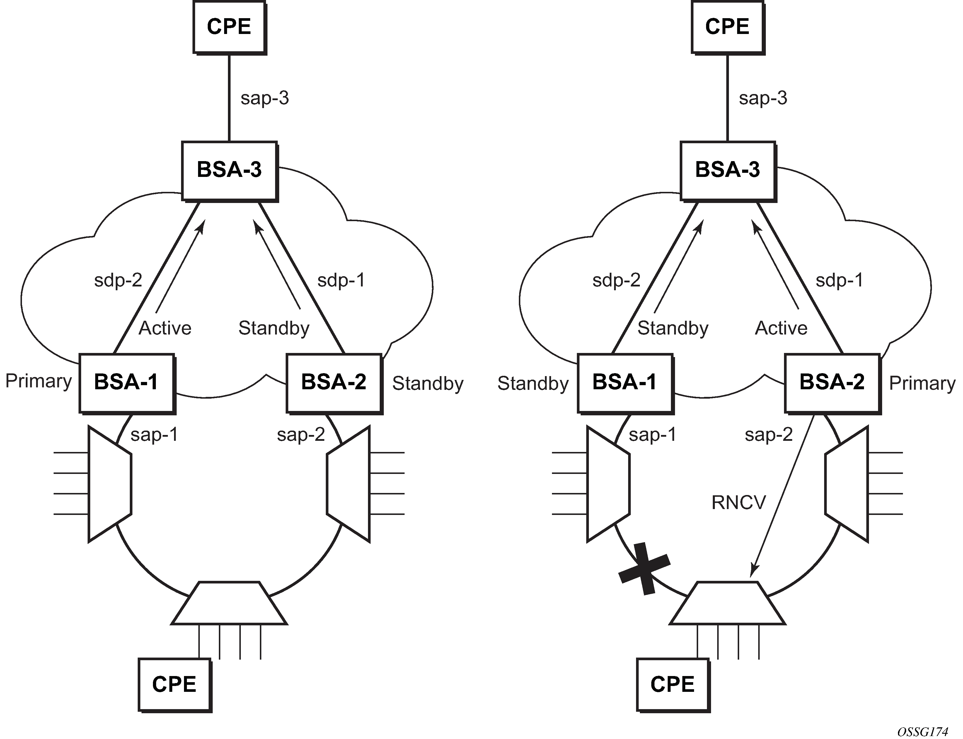
To support redundant VLL access in ring configurations, the multichassis ring (MC-Ring) feature is applicable to VLL SAPs. A conceptual drawing of the operation is shown in MC-Ring in a combination with VLL service. The specific CPE that is connected behind the ring node has access to both BSAs through the same VLAN provisioned in all ring nodes. There are two SAPs (with the same VLAN) provisioned on both nodes.
If a closed ring status occurs, one of the BSAs becomes the primary BSA and signals an active status bit on the corresponding VLL pseudowire. Similarly, the standby BSA signals a standby status. With this information, the remote node can choose the correct path to reach the CPE. In case of a broken ring, the node that can reach the ring node, to which the CPE is connected by RNCV check, becomes the primary and signals corresponding status on its pseudowire.
The mapping of individual SAPs to the ring nodes is done statically through CLI provisioning. To keep the convergence time to a minimum, MAC learning must be disabled on the ring node so all CPE originated traffic is sent in both directions. If the status is operationally down on the SAP on the standby BSA, that part of the traffic is blocked and not forwarded to the remote site.
Pseudowire redundancy service models
This section describes the MC-LAG and pseudowire redundancy scenarios and the algorithm used to select the active transmit object in a VLL endpoint.
Redundant VLL service model
To implement pseudowire redundancy, a VLL service accommodates more than a single object on the SAP side and on the spoke-SDP side.
The following figure shows the model for a redundant VLL service based on the concept of endpoints.
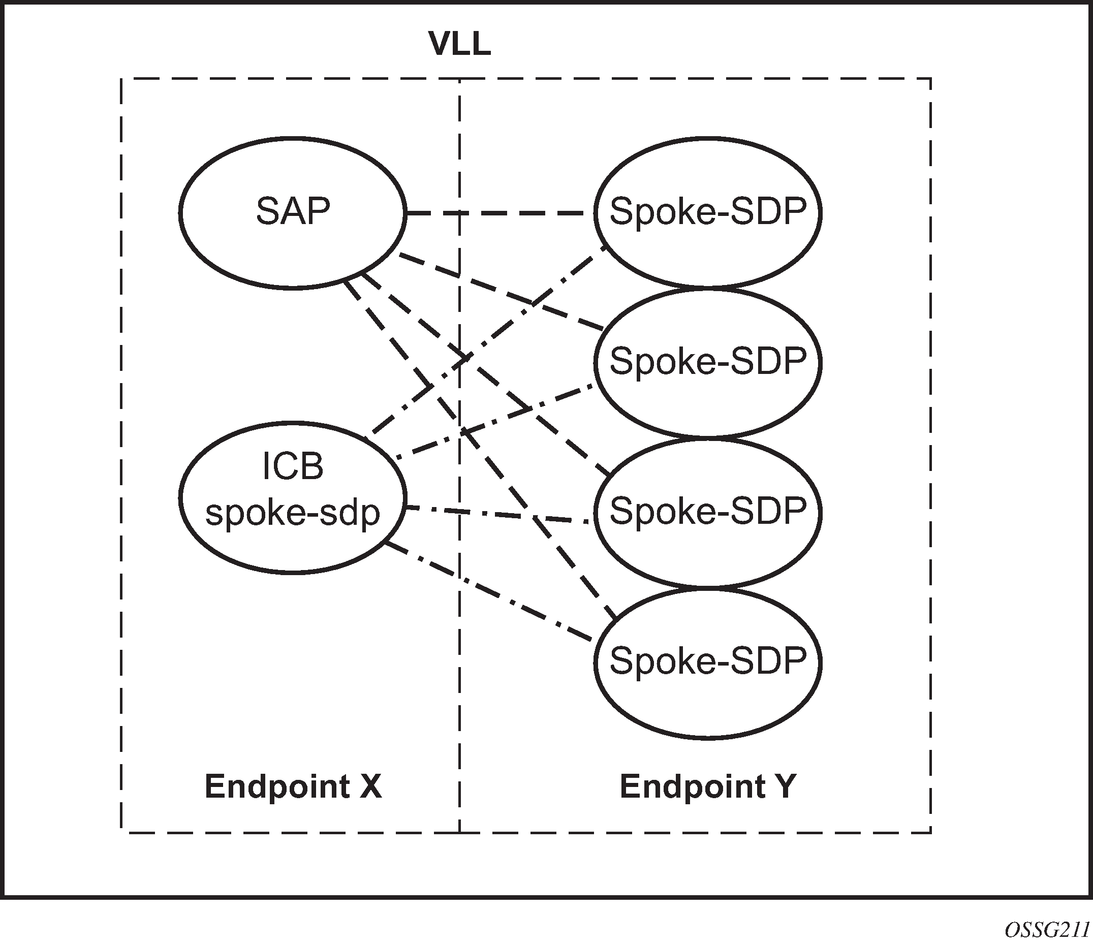
By default, a VLL service supports two implicit endpoints managed internally by the system. Each endpoint can only have one object: a SAP or a spoke-SDP.
To add more objects, create up to two explicitly named endpoints per VLL service. The endpoint name is locally significant to the VLL service. In the preceding figure, endpoints are referred to as endpoint X and endpoint Y.
In the preceding figure, endpoint Y can also have a SAP or an ICB spoke-SDP. The following is a list of supported endpoint objects, and the applicable rules to associate the object with an endpoint of a VLL service:
SAP
A maximum of only one SAP per VLL endpoint is supported.
primary spoke-SDP
The VLL service always uses this pseudowire and only switches to a secondary pseudowire when this primary pseudowire is down; the VLL service switches the path to the primary pseudowire when it is back up. The user can configure a timer to delay reverting back to primary or to never revert. A maximum of only one primary spoke-SDP per VLL endpoint is supported.
secondary spoke-SDP
A maximum of four secondary spoke-SDPs per endpoint are supported. The user can configure the precedence of a secondary pseudowire to indicate the order in which a secondary pseudowire is activated.
Inter-Chassis Backup (ICB) spoke-SDP
This special pseudowire is used for MC-LAG and pseudowire redundancy applications. Forwarding between ICBs is blocked on the same node. At the time this endpoint object is created, the user must explicitly indicate that the spoke-SDP is an ICB; however, a few scenarios are possible where the user can configure the spoke-SDP as an ICB or as a regular spoke-SDP on a specified node. The CLI for those cases indicate both options.
A VLL service endpoint can use only a single active object to transmit at a specific time, but it can receive from all endpoint objects.
An explicitly named endpoint can have a maximum of one SAP and one ICB. When a SAP is added to the endpoint, only one more object of the ICB spoke-SDP type is allowed. The ICB spoke-SDP cannot be added to the endpoint if the SAP is not part of an MC-LAG instance. Conversely, a SAP that is not part of an MC-LAG instance cannot be added to an endpoint that already has an ICB spoke-SDP.
An explicitly named endpoint that does not have a SAP object can have a maximum of four spoke-SDPs and include any of the following:
a single primary spoke-SDP
one or many secondary spoke-SDPs with precedence
a single ICB spoke-SDP
T-LDP status notification handling rules
Using Redundant VLL endpoint objects as a reference, this section describes the rules for generating, processing, and merging T-LDP status notifications in a VLL service with endpoints. Any allowed combination of objects, as specified in Redundant VLL service model, can be used on endpoints X and Y.
This section uses the specific combination of objects shown in Redundant VLL endpoint objects as an example to describe the more general rules.
Processing endpoint SAP active/standby status bits
The advertised administrative forwarding status bit of active/standby reflects the status of the local LAG SAP in MC-LAG applications. If the SAP is not part of an MC-LAG instance, the forwarding status of active is always advertised.
If the SAP in endpoint X is part of an MC-LAG instance, a node must send a T-LDP forwarding status bit of SAP active/standby over all endpoint Y spoke-SDPs, except the ICB spoke-SDP, whenever this status changes. The status bit sent over the ICB is always zero (active by default).
If the SAP in endpoint X is not part of an MC-LAG instance, the forwarding status sent over all endpoint Y spoke-SDPs should always be set to zero (active by default).
Processing and merging
Endpoint X is operationally up if at least one of its objects is operationally up. It is down if all of its objects are operationally down.
If the SAP in endpoint X transitions locally to the down state or receives a SAP down notification via the SAP-specific OAM signal, the node must send T-LDP SAP down status bits on endpoint Y ICB spoke SDPs only. Ethernet SAP does not support the SAP OAM protocol. No other SAP types can exist on the same endpoint as an ICB spoke SDP because a non-Ethernet SAP cannot be part of an MC-LAG instance.
If the ICB spoke SDP in endpoint X transitions locally to the down state, the node must send T-LDP SDP-binding down status bits on this spoke SDP.
If the ICB spoke SDP in endpoint X receives T-LDP SDP-binding down status bits or the pseudowire does not forward the status bits, the node saves this status and takes no further action. The saved status is used for active transmit endpoint object selection.
If any or all of the following are true for all objects in endpoint X, the node must send status bits of SAP down over all endpoint Y spoke SDPs, including the ICB:
transitioned locally to down state
received a SAP down notification by remote T-LDP status bits or by SAP-specific OAM signal
received SDP-binding down status bits
received PW not forwarding status bits
Endpoint Y is operationally up if at least one of its objects is operationally up. It is down if all its objects are operationally down.
If a spoke SDP in endpoint Y, including the ICB spoke SDP, transitions locally to the down state, the node must send T-LDP SDP-binding down status bits on this spoke SDP.
If any or all of the following are true for a spoke SDP in endpoint Y, including the ICB spoke SDP, the node saves this status and takes no further action:
received T-LDP SAP down status bits
received T-LDP SDP-binding down status bits
received PW not forwarding status bits
The saved status is used for selecting the active transmit endpoint object.
If any or all of the following are true for all objects in endpoint Y, except the ICB spoke SDP, the node must send status bits of SDP-binding down over the X endpoint ICB spoke SDP only:
transitioned locally to the down state
received T-LDP SAP down status bits
received T-LDP SDP-binding down status bits
received PW not forwarding status bits
If any or all of the following are true for all objects in endpoint Y, the node must send status bits of SDP-binding down over the X endpoint ICB spoke SDP, and must send a SAP down notification on the X endpoint SAP by the SAP-specific OAM signal, if applicable:
transitioned locally to down state
received T-LDP SAP down status bits
received T-LDP SDP-binding down status bits
received PW not forwarding status bits
An Ethernet SAP does not support signaling status notifications.
VLL using G.8031 protected Ethernet tunnels
The use of MPLS tunnels provides the 7705 SAR Gen 2 a way to scale the core while offering fast failover times using MPLS FRR. In environments where Ethernet services are deployed using native Ethernet backbones, Ethernet tunnels are provided to achieve the same fast failover times as in the MPLS FRR case.
The Nokia VLL implementation offers the capability to use core Ethernet tunnels compliant with ITU-T G.8031 specification to achieve 50 ms resiliency for backbone failures. This is required to comply with the stringent SLAs provided by service providers. Epipe and Ipipe services are supported.
When using Ethernet tunnels, the Ethernet tunnel logical interface is created first. The Ethernet tunnel has member ports, which are the physical ports supporting the links. The Ethernet tunnel control SAPs carry G.8031 and 802.1ag control traffic and user data traffic. Ethernet service SAPs are configured on the Ethernet tunnel. Optionally, when tunnels follow the same paths, end-to-end services may be configured with fate shared Ethernet tunnel SAPs, which carry only user data traffic and share the fate of the Ethernet tunnel port (if correctly configured).
Ethernet tunnels provide a logical interface that VLL SAPs may use just as regular interfaces. The Ethernet tunnel provides resiliency by providing end-to-end tunnels. The tunnels are stitched together by VPLS or Epipe services at intermediate points. Epipes offer a more scalable option.
For further information, see the 7705 SAR Gen 2 Services Overview Guide.
MPLS hash label
The router supports the Flow Aware Transport label, known as the hash label (RFC 6391). LSR nodes in a network can load-balance labeled packets in a more granular way than by hashing on the standard label stack. See the 7705 SAR Gen 2 MPLS Guide for more information.
configure service epipe spoke-sdp hash-labelconfigure service pw-template hash-labelBGP VPWS
BGP Virtual Private Wire Service (VPWS) is a point-to-point Layer 2 VPN service based on RFC 6624 Layer 2 Virtual Private Networks using BGP for Auto-Discovery and Signaling, which in turn uses the BGP pseudowire signaling concepts described in RFC 4761, Virtual Private LAN Service Using BGP for Auto-Discovery and Signaling.
The BGP-signaled pseudowires created can use either automatic or preprovisioned SDPs over LDP- or BGP-signaled tunnels; the choice of tunnel depends on the tunnel's preference in the tunnel table, or over GRE. Preprovisioned SDPs must be configured when RSVP signaled transport tunnels are used.
The use of an automatically created GRE tunnel is enabled by creating the PW template used within the service with the parameter auto-gre-sdp. The GRE SDP and SDP binding are created after a matching BGP route is received.
Inter-AS model C and dual-homing are supported.
Single-homed BGP VPWS
A single-homed BGP VPWS service is implemented as an Epipe connecting a SAP or static GRE tunnel (a spoke-SDP using a GRE SDP configured with static MPLS labels) and a BGP signaled pseudowire, maintaining the Epipe properties such as no MAC learning. The MPLS pseudowire data plane uses a two-label stack; the inner label is derived from the BGP signaling and identifies the Epipe service while the outer label is the tunnel label of an LSP transporting the traffic between the two end systems.
The following figure shows how this service would be used to provide a virtual leased line service (VLL) across an MPLS network between sites A and B.
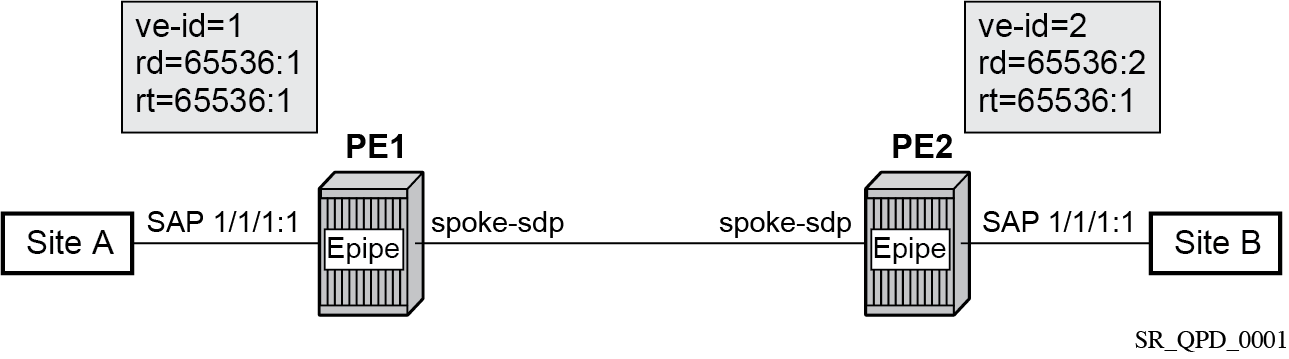
An Epipe is configured on PE1 and PE2 with BGP VPWS enabled. PE1 and PE2 are connected to site A and B, respectively, each using a SAP. The interconnection between the two PEs is achieved through a pseudowire that is signaled using BGP VPWS updates over a specific tunnel LSP.
Dual-homed BGP VPWS
A BGP-VPWS service can benefit from dual-homing, as described in IETF Draft draft-ietf-bess-vpls-multihoming-01. When using dual-homing, two PEs connect to a site, with one PE being the designated forwarder (DF) for the site and the other blocking its connection to the site. On failure of the active PE, its pseudowire, or its connection to the site, the other PE becomes the DF and unblocks its connection to the site.
Single pseudowire example
A pseudowire is established between the DF of the dual-homed PEs and the remote PE. If a failure causes a change in the DF, the pseudowire is deleted and reestablished between the remote PE and the new DF. This topology requires that the VE IDs on the dual-homed PEs are set to the same value.
The following figure shows an example of a dual-homed, single pseudowire topology.
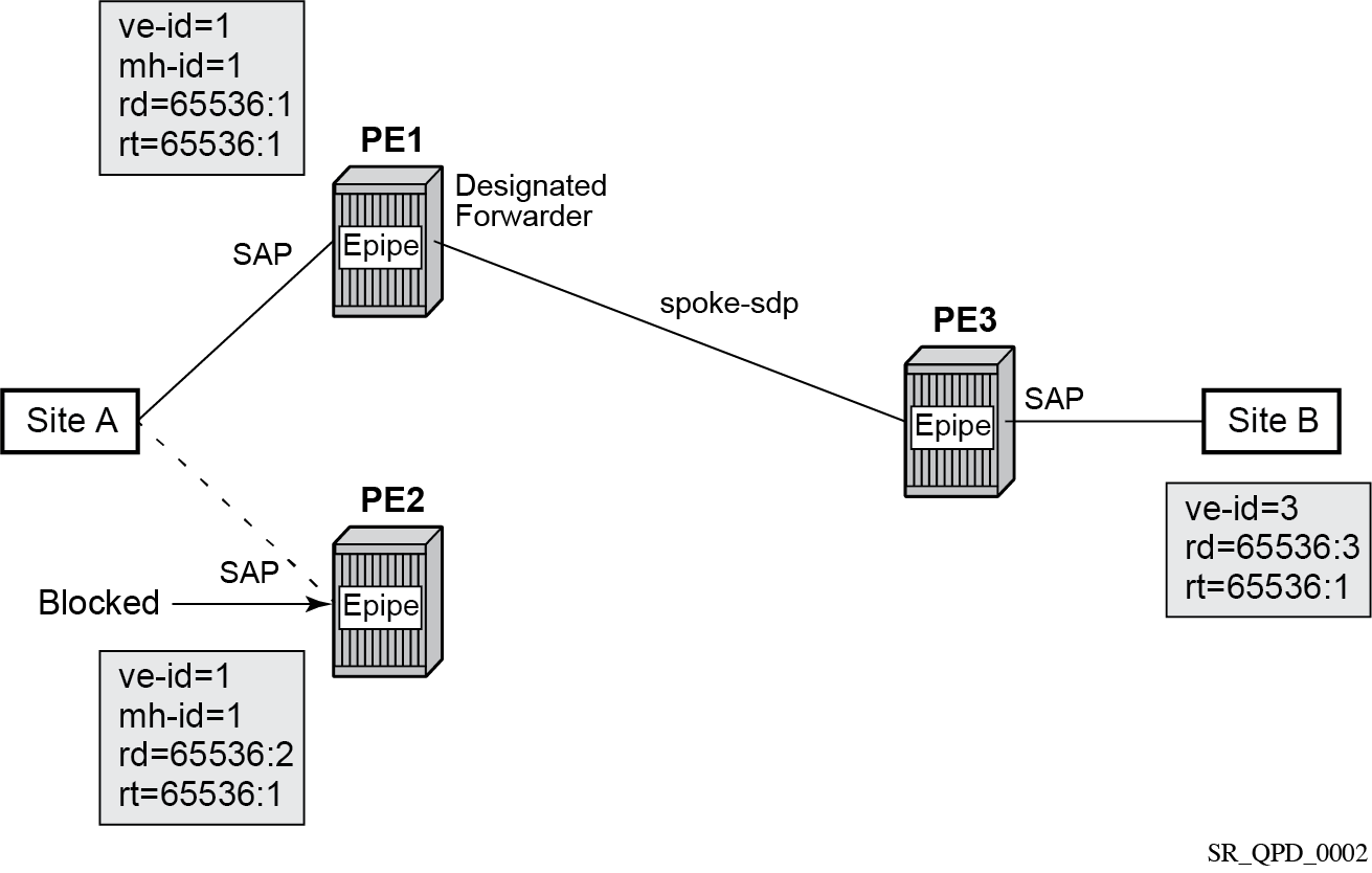
An Epipe with BGP VPWS enabled is configured on each PE. Site A is dual-homed to PE1 and PE2 with the remote PE (PE3) connecting to site B. An Epipe service is configured on each PE in which there is a SAP connecting to the local site.
The pair of dual-homed PEs perform a DF election, which is influenced by BGP route selection, the site state, and configuration of the site-preference. A site is only eligible to be the DF if it is up (the site state is down if there is no pseudowire established or if the pseudowire is in an operationally down state). The winner, for example PE1, becomes the active switch for traffic sent to and from site A, while the loser blocks its connection to site A.
Pseudowires are signaled using BGP from PE1 and PE2 to PE3, but only from PE3 to the DF in the opposite direction (so only one bidirectional pseudowire is established). There is no pseudowire between PE1 and PE2; this is achieved by configuration.
Traffic is sent and received traffic on the pseudowire connected between PE3 and the DF, PE1.
If the site state is operationally down, both the D and Circuit Status Vector (CSV) bits (see the following for more details) are set in the BGP-VPWS update, which causes the remote PE to use the pseudowire to the new DF.
Active/standby pseudowire example
Pseudowires are established between the remote PE and each dual-homed PE. The remote PE can receive traffic on either pseudowire, but only sends on the one to the designated forwarder. This creates an active/standby pair of pseudowires. At most, one standby pseudowire is established; this being determined using the tie-breaking rules defined in the multihoming draft. This topology requires each PE to have a different VE ID.
The following figure shows an example of a dual-homed, active/standby pseudowires topology.
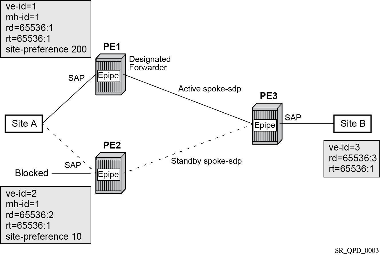
An Epipe with BGP VPWS enabled is configured on each PE. Site A is dual-homed to PE1 and PE2 with the remote PE (PE3) connecting to site B. An Epipe service is configured on each PE in which there is a SAP connecting to the local site.
The pair of dual-homed PEs perform a designated forwarder election, which is influenced by configuring the site-preference value. The winner, PE1 (based on its higher site-preference value) becomes the active switch for traffic sent to and from site A, while the loser, PE2, blocks its connection to site A. Pseudowires are signaled using BGP between PE1 and PE3, and between PE2 and PE3. There is no pseudowire between PE1 and PE2; this is achieved by configuration. The active/standby pseudowires on PE3 are part of an endpoint automatically created in the Epipe service.
Traffic is sent and received on the pseudowire connected to the designated forwarder, PE1.
BGP VPWS pseudowire switching
Pseudowire switching is supported with a BGP VPWS service allowing the cross connection between a BGP VPWS signaled spoke-SDP and a static GRE tunnel, the latter being a spoke SDP configured with static MPLS labels using a GRE SDP. No other spoke SDP types are supported. Support is not included for BGP multihoming using an active and a standby pseudowire to a pair of remote PEs.
Operational state changes to the GRE tunnel are reflected in the state of the Epipe and propagated accordingly in the BGP VPWS spoke SDP status signaling, specifically using the BGP update D and CSV bits.
The following configuration is required:
The Epipe service must be created using the vc-switching parameter.
The GRE tunnel spoke SDP must be configured using a GRE SDP with signaling off and have the ingress and egress vc-labels statically configured.
Example: BGP VPWS service configured to allow pseudowire switching
configure
    service
        sdp 1 create
            signaling off
            far-end 192.168.1.1
            keep-alive
                shutdown
            exit
            no shutdown
        exit
        pw-template 1 create
        exit
        epipe 1 customer 1 vc-switching create
            description "BGP VPWS service"
            bgp
                route-distinguisher 65536:1
                route-target export target:65536:1 import target:65536:1
                pw-template-binding 1
                exit
            exit
            bgp-vpws
                ve-name "PE1"
                    ve-id 1
                exit
                remote-ve-name "PE2"
                    ve-id 2
                exit
                no shutdown
            exit
            spoke-sdp 1:1 create
                ingress
                    vc-label 1111
                exit
                egress
                    vc-label 1122
                exit
                no shutdown
            exit
            no shutdown
        exit
Pseudowire signaling
The BGP signaling mechanism used to establish the pseudowires is described in the BGP VPWS standards with the following differences:
-
As stated in Section 3 of RFC 6624, there are two modifications of messages when compared to RFC 4761:
-
the Encaps Types supported in the associated extended community
-
the addition of a circuit status vector sub-TLV at the end of the VPWS NLRI
-
-
The control flags and VPLS preference in the associated extended community are based on IETF Draft draft-ietf-bess-vpls-multihoming-01.
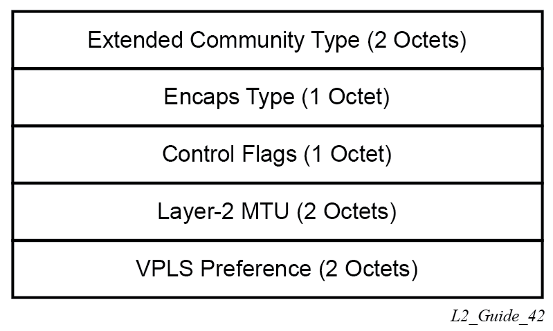
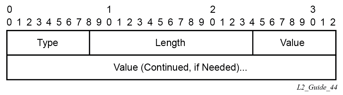
The following figure shows the format of the BGP VPWS update extended community.
-
extended community type
This is the value allocated by IANA for this attribute is 0x800A.
-
encaps type
The encapsulation type identifies the type of pseudowire encapsulation. Ethernet VLAN (4) and Ethernet Raw mode (5), as described in RFC 4448, are the only values supported. If there is a mismatch between the Encaps Type signaled and the one received, the pseudowire is created but with the operationally down state.
-
control flags
This is control information concerning the pseudowires, see Control flags for more information.
-
Layer 2 MTU
This is the MTU to be used on the pseudowires. If the received Layer 2 MTU is zero, no MTU check is performed and the related pseudowire is established. If there is a mismatch between the local service-mtu and the received Layer 2 MTU, the pseudowire is created with the operationally down state and an MTU/Parameter mismatch indication.
-
VPLS preference
VPLS preference has a default value of zero for BGP-VPWS updates sent by the system, indicating that it is not in use. If the site-preference is configured, its value is used for the VPLS preference and is also used in the local designated forwarder election.
On receipt of a BGP VPWS update containing a non-zero value, it is used to determine to which system the pseudowire is established, as part of the VPWS update process tie-breaking rules. The BGP local preference of the BGP VPWS update sent by the system is set to the same value as the VPLS preference if the latter is non-zero, as required by the draft (as long as the D bit in the extended community is not set to 1). Consequently, attempts to change the BGP local preference when exporting a BGP VPWS update with a non-zero VPLS preference is ignored. This prevents the updates being treated as malformed by the receiver of the update.
For inter-AS, the preference information must be propagated between autonomous systems using the VPLS preference. Consequently, if the VPLS preference in a BGP-VPWS or BGP multihoming update is zero, the local preference is copied by the egress ASBR into the VPLS preference field before sending the update to the External Border Gateway Protocol (EBGP) peer. The adjacent ingress ASBR then copies the received VPLS preference into the local preference to prevent the update from being considered malformed.
The following figure shows the pseudowire control flags.

The following bits in the Control Flags are defined:
- D
- Access circuit down indicator from IETF Draft draft-kothari-l2vpn-auto-site-id-01. D is 1 if all access circuits are down, otherwise D is 0.
- A
- Automatic site ID allocation, which is not supported. This is ignored on receipt and set to 0 on sending.
- F
- MAC flush indicator. This is not supported because it relates to a VPLS service. This is set to 0 and ignored on receipt.
- C
- Presence of a control word. Control word usage is supported. When this is set to 1, packets are sent and are expected to be received with a control word. When this is set to 0, packets are sent and are expected to be received without a control word (by default).
- S
- Sequenced delivery. Sequenced delivery is not supported. This is set to 0 on sending (no sequenced delivery) and, if a non-zero value is received (indicating sequenced delivery required), the pseudowire is not created.
The BGP VPWS NLRI is based on that defined for BGP VPLS, but is extended with a circuit status vector, as shown in the following figure.
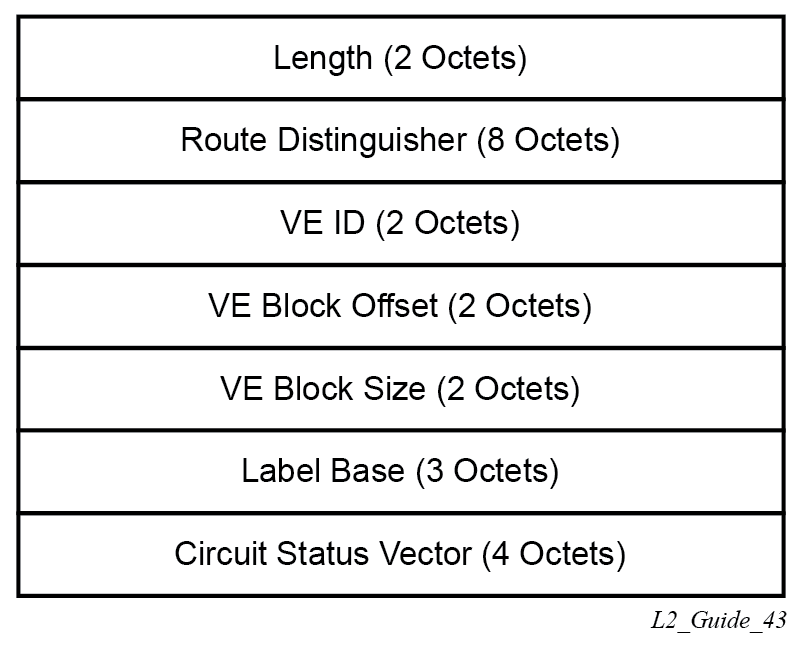
The VE ID value is configured within each BGP VPWS service, the label base is chosen by the system, and the VE block offset corresponds to the remote VE ID because a VE block size of 1 is always used.
The circuit status vector is encoded as a TLV, as shown in BGP VPWS NLRI TLV extension format and Circuit status vector TLV type.
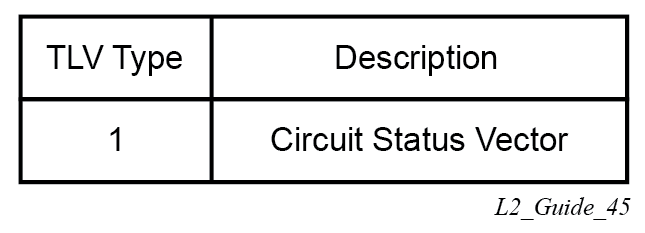
The circuit status vector is used to indicate the status of both the SAP/GRE tunnel and the status of the spoke-SDP within the local service. Because the VE block size used is 1, the most significant bit in the circuit status vector TLV value is set to 1 if either the SAP/GRE tunnel or spoke-SDP is down, otherwise it is set to 0. On receiving a circuit status vector, only the most significant byte of the CSV is examined for designated forwarder selection purposes.
If a circuit status vector length field of greater than 32 is received, the update is ignored and not reflected to BGP neighbors. If the length field is greater than 800, a notification message is sent and the BGP session restarts. Also, BGP VPWS services support a single access circuit, so only the most significant bit of the CSV is examined on receipt.
A pseudowire is established when a BGP VPWS update is received that matches the service configuration, specifically the configured route targets and remote VE ID. If multiple matching updates are received, the system to which the pseudowire is established is determined by the tie-breaking rules, as described in IETF Draft draft-ietf-bess-vpls-multihoming-01.
Traffic is sent on the active pseudowire connected to the remote designated forwarder. Traffic can be received on either the active or standby pseudowire, although no traffic should be received on the standby pseudowire because the SAP/GRE tunnel on the non-designated forwarder should be blocked.
The adv-service-mtu command can be used to override the MTU value used in BGP signaling to the far-end of the pseudowire. This value is also used to validate the value signaled by the far-end PE unless ignore-l2vpn-mtu-mismatch is also configured.
If the ignore-l2vpn-mtu-mismatch command is configured, the router does not check the value of the "Layer 2 MTU" in the "Layer2 Info Extended Community" received in a BGP update message against the local service MTU, or against the MTU value signaled by this router. The router brings up the BGP VPLS service regardless of any MTU mismatch.
BGP-VPWS with inter-AS model C
BGP VPWS with inter-AS model C is supported both in a single-homed and dual-homed configuration.
When dual-homing is used, the dual-homed PEs must have different values configured for the site-preference (under the site within the Epipe service) to allow the PEs in a different AS to select the designated forwarder when all access circuits are up. The value configured for the site-preference is propagated between autonomous systems in the BGP VPWS and BGP multihoming update extended community VPLS preference field. The receiving ingress ASBR copies the VPLS preference value into local preference of the update to ensure that the VPLS preference and local preference are equal, which prevents the update from being considered malformed.
BGP VPWS configuration procedure
In addition to configuring the associated BGP and MPLS infrastructure, the provisioning of a BGP VPWS service requires:
-
configuring the BGP Route Distinguisher, Route Target
The updates are accepted into the service only if they contain the configured import route-target.
-
configuring a binding to the pseudowire template
The multiple pseudowire template bindings can be configured with their associated route-targets used to control which is applied.
-
configuring the SAP or static GRE tunnel
-
configuring the name of the local VE and its associate VE ID
-
configuring the name of the remote VE and its associated VE ID
-
for a dual-homed PE:
-
enabling the site
-
configuring the site with non-zero site-preference
-
-
for a remote PE, configuring up to two remote VE names and associated VE IDs
-
enabling BGP VPWS
Use of pseudowire template for BGP VPWS
The pseudowire template concept used for BGP AD is reused for BGP VPWS to dynamically instantiate pseudowires (SDP-bindings) and the related SDPs (provisioned or automatically instantiated).
The settings for the L2-Info extended community in the BGP update sent by the system are derived from the pw-template attributes. The following rules apply:
If multiple pw-template-bindings (with or without import-rt) are specified for the VPWS instance, the first (numerically lowest ID) pw-template entry is used.
Both Ethernet VLAN and Ethernet Raw Mode Encaps Types are supported; these are selected by configuring the vc-type in the pseudowire template to be either vlan or ether, respectively. The default is ether.
The same value must be used by the remote BGP VPWS instance to ensure that the related pseudowire comes up.Layer 2 MTU is derived from the service VPLS service-mtu parameter.
The same value must be used by the remote BGP VPWS instance to ensure that the related pseudowire comes up.Control Flag C can be 0 or 1, depending on the setting of the control-word parameter in the PW template 0.
Control Flag S is always 0.
On reception, the values of the parameters in the L2-Info extended community of the BGP update are compared with the settings from the corresponding pw-template. The following steps are used to determine the local pw-template:
The route-target values are matched to determine the pw-template. The binding configured with the first matching route target is chosen.
If a match is not found from the previous step, the lowest pw-template-binding (numerically) without any route-target configured is used.
If the values used for encap-type or Layer 2 MTU do not match, the pseudowire is created but with the operationally down state.
To interoperate with existing implementations, if the received MTU value = 0, the MTU negotiation does not take place; the related pseudowire is set up ignoring the MTU.If the value of the S flag is not zero, the pseudowire is not created.
The following pseudowire template parameters are supported when applied within a BGP VPWS service; the remainder are ignored:
configure service pw-template policy-id [use-provisioned-sdp |
       [prefer-provisioned-sdp] [auto-sdp]] [create] [name name]
   accounting-policy acct-policy-id
   no accounting-policy
   [no] collect-stats
   [no] controlword
   egress
      filter ipv6 ipv6-filter-id
      filter ip ip-filter-id
      filter mac mac-filter-id
      no filter [ip ip-filter-id] [mac mac-filter-id] [ipv6 ipv6-filter-id]
      qos network-policy-id port-redirect-group queue-group-name instance instance
id
      no qos [network-policy-id]
   [no] force-vlan-vc-forwarding
   hash-label [signal-capability]
   no hash-label
   ingress
      filter ipv6 ipv6-filter-id
      filter ip ip-filter-id
      filter mac mac-filter-id
      no filter [ip ip-filter-id] [mac mac-filter-id] [ipv6 ipv6-filter-id]
      qos network-policy-id fp-redirect-group queue-group-name instance instance-id
      no qos [network-policy-id]
   [no] sdp-exclude
   [no] sdp-include
   vc-type {ether | vlan}
   vlan-vc-tag vlan-id
   no vlan-vc-tag
For more information about this command, see the 7705 SAR Gen 2 Services Overview Guide.
The use-provisioned-sdp option is permitted when creating the pseudowire template if a preprovisioned SDP is to be used. Preprovisioned SDPs must be configured whenever RSVP-signaled transport tunnels are used.
When the prefer-provisioned-sdp option is specified, if the system finds an existing matching SDP that conforms to any restrictions defined in the pseudowire template (for example, sdp-include or sdp-exclude group), it uses this matching SDP (even if the existing SDP is operationally down); otherwise, it automatically creates an SDP.
When the auto-gre-sdp option is specified, a GRE SDP is automatically created.
The tools perform command can be used in the same way as for BGP-AD to apply changes to the pseudowire template using the following format:
tools perform service [id service-id] eval-pw-template policy-id [allow-service-impact]
If a user configures a service using a pseudowire template with the prefer-provisioned-sdp option, but without provisioning an applicable SDP, and the system binds to an automatic SDP, and the user subsequently provisions an appropriate SDP, the system does not automatically switch to the new provisioned SDP. This only occurs if the pseudowire template is reevaluated using the tools perform service id service-id eval-pw-template command.
Use of endpoint for BGP VPWS
An endpoint is required on a remote PE connecting to two dual-homed PEs to associate the active/standby pseudowires with the Epipe service. An endpoint is automatically created within the Epipe service such that active/standby pseudowires are associated with that endpoint. The creation of the endpoint occurs when bgp-vpws is enabled (and deleted when it is disabled) and so exists in both a single- and dual-homed scenario. This simplifies converting a single-homed service to a dual-homed service. The naming convention used is _tmnx_BgpVpws-x, where x is the service identifier. The automatically created endpoint has the default parameter values, although all are ignored in a BGP-VPWS service with the description field being defined by the system.
The following command does not have any effect on an automatically created VPWS endpoint:
tools perform service id <service-id> endpoint <endpoint-name> force-switchover
VLL service considerations
This section describes the general service features and any special capabilities or considerations as they relate to VLL services.
SDPs
The most basic SDPs must include the following:
a locally unique SDP identification (ID) number
the system IP address of the originating and far-end routers
-
an SDP encapsulation type, either GRE or MPLS
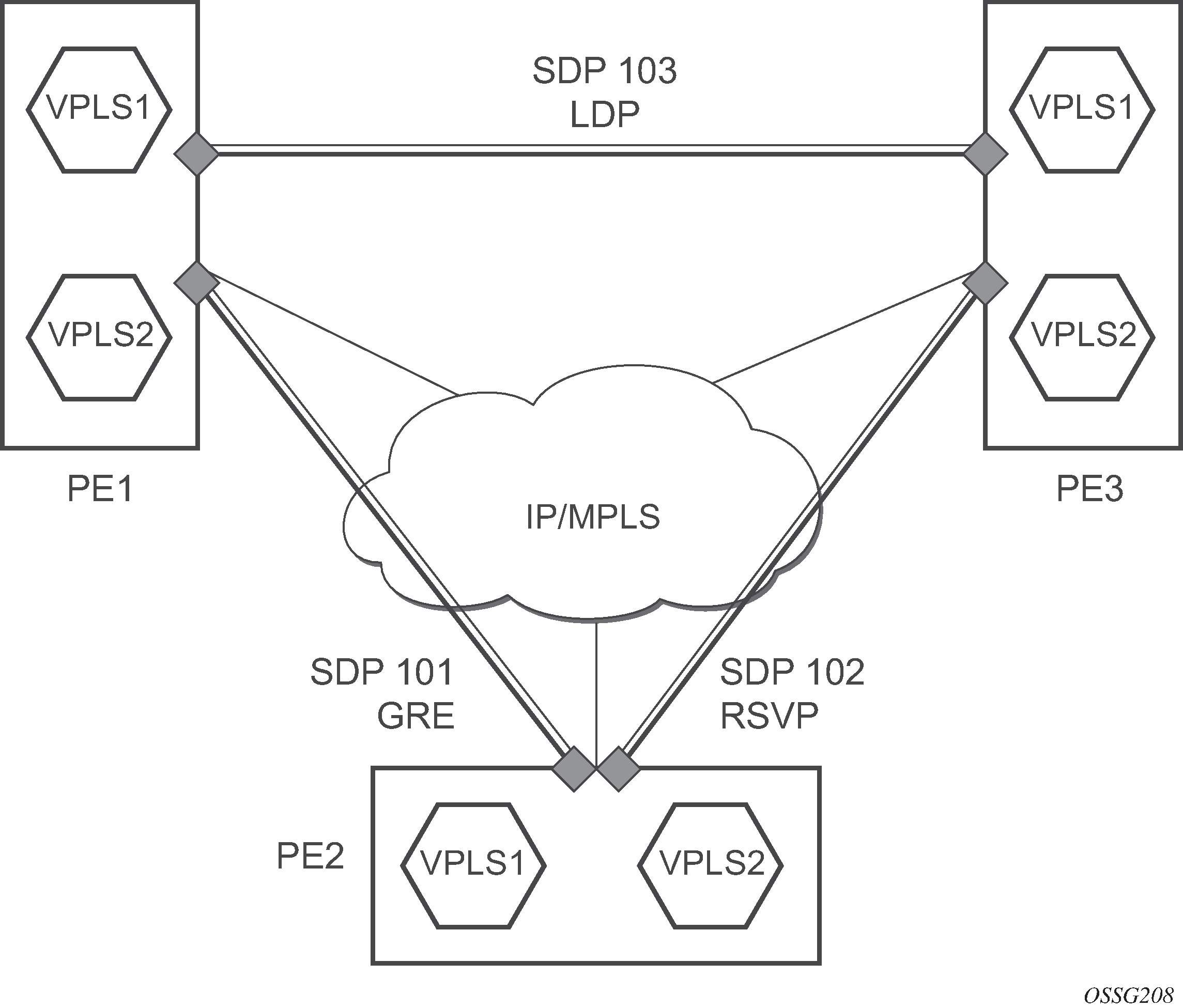
SDP statistics for VPLS and VLL services
The three-node network in SDP statistics for VPLS and VLL services shows two MPLS SDPs and one GRE SDP defined between the nodes. These SDPs connect VPLS1 and VPLS2 instances that are defined in the three nodes. With this feature, the operator has local CLI-based and SNMP-based statistics collection for each VC used in the SDPs. This allows for traffic management of tunnel usage by the different services and with aggregation the total tunnel usage.
SAP encapsulations and pseudowire types
The Epipe service is designed to carry Ethernet frame payloads, so it can provide connectivity between any two SAPs that pass Ethernet frames.
The following SAP encapsulations are supported on the Epipe service:
-
Ethernet null
-
Ethernet dot1q
-
QinQ
While different encapsulation types can be used, encapsulation mismatch can occur if the encapsulation behavior is not understood by connecting devices, which are unable to send and receive the expected traffic. For example, if the encapsulation type on one side of the Epipe is dot1q and the other is null, tagged traffic received on the null SAP is double-tagged when it is transmitted out of the dot1q SAP.
One pseudowire encapsulation mode, that is, SDP vc-type, is available: PWE3 N-to-1 Cell Mode Encapsulation.
QoS policies
When applied to Epipe services, service ingress QoS policies only create the unicast queues defined in the policy. The multipoint queues are not created on the service.
With Epipe services, egress QoS policies function as with other services where the class-based queues are created as defined in the policy. Both Layer 2 or Layer 3 criteria can be used in the QoS policies for traffic classification in a service.
Filter policies
Epipe and Ipipe services can have a single filter policy associated on both ingress and egress. Both MAC and IP filter policies can be used on Epipe services.
MAC resources
Epipe services are point-to-point Layer 2 VPNs capable of carrying any Ethernet payloads. Although an Epipe is a Layer 2 service, the 7705 SAR Gen 2 Epipe implementation does not perform any MAC learning on the service, so Epipe services do not consume any MAC hardware resources.
Configuring a VLL service using CLI
This section provides information to configure VLL services using the CLI.
Common configuration tasks
This section provides a brief overview of the tasks that must be performed to configure VLL services and the associated CLI commands.
-
Associate the service with a customer ID.
-
Define SAP parameters.
-
Optional - select egress and ingress QoS or scheduler policies, or both (configured in the config>qos context).
-
Optional - select accounting policy (configured in the config>log context)
-
-
Define spoke-SDP parameters.
-
Enable the service.
Configuring VLL components
This section provides VLL configuration examples for the VLL services.
Creating an Epipe service
Use the following CLI syntax to create an Epipe service.
CLI syntax:
config>service# epipe service-id [customer customer-id] [vpn vpn-id] [vc-switching]
description description-string
no shutdown
The following example shows an Epipe configuration:
A:ALA-1>config>service# info
-------------------------------------------
...
        epipe 500 customer 5 vpn 500 create
            description "Local epipe service"
            no shutdown
        exit
-------------------------------------------
A:ALA-1>config>service#
Configuring Epipe SAP parameters
A default QoS policy is applied to each ingress and egress SAP. Additional QoS policies can be configured in the config>qos context. Filter policies are configured in the config>filter context and explicitly applied to a SAP. There are no default filter policies.
Use the following CLI syntax to create:
CLI syntax:
config>service# epipe service-id [customer customer-id]
    — sap sap-id [endpoint endpoint-name]
    — sap sap-id [no-endpoint]
        — accounting-policy policy-id
        — collect-stats
        — description description-string
        — no shutdown
        — egress
            — filter {ip ip-filter-name | mac mac-filter-name}
            — qos sap-egress-policy-id
            — scheduler-policy scheduler-policy-name
        — ingress
            — filter {ip ip-filter-name | mac mac-filter-name}
            — match-qinq-dot1p {top | bottom}
            — qos policy-id [shared-queuing]
            — scheduler-policy scheduler-policy-name
Local Epipe SAPs
To configure a basic local Epipe service, enter the sap sap-id command twice with different port IDs in the same service configuration.
By default, QoS policy ID 1 is applied to ingress and egress service SAPs. Existing filter policies or other existing QoS policies can be associated with service SAPs on ingress and egress ports. Supported SAP types shows supported SAP types.
| Uplink type | Svc SAP type | Cust. VID | Access SAPs | Network SAPs |
|---|---|---|---|---|
L2 |
Null-star |
— |
Null, dot1q * |
Q.* |
L2 |
Dot1q |
— |
Dot1q |
Q.* |
L2 |
Dot1q-preserve |
— |
Dot1q (encap = X) |
Q1.Q2 (where Q2 = X) |
An existing scheduler policy can be applied to ingress and egress SAPs to be used by the SAP queues and, at egress only, policers. The schedulers comprising the policy are created when the scheduler policy is applied to the SAP. If any policers or orphaned queues (with a non-existent local scheduler defined) exist on a SAP and the policy application creates the required scheduler, the status on the queue becomes non-orphaned at this time.
Ingress and egress SAP parameters can be applied to local and distributed Epipe service SAPs.
The following example shows the SAP configurations for local Epipe service 500 on SAP 1/1/2 and SAP 1/1/3 on ALA-1:
A:ALA-1>config>service# epipe 500 customer 5 create
    config>service>epipe$ description "Local epipe service"
    config>service>epipe# sap 1/1/2:0 create
    config>service>epipe>sap? ingress
    config>service>epipe>sap>ingress# qos 20
    config>service>epipe>sap>ingress# filter ip 1
    config>service>epipe>sap>ingress# exit
    config>service>epipe>sap# egress
    config>service>epipe>sap>egress# qos 20
    config>service>epipe>sap>egress# scheduler-policy test1
    config>service>epipe>sap>egress# exit
    config>service>epipe>sap# no shutdown
    config>service>epipe>sap# exit

    config>service>epipe# sap 1/1/3:0 create
    config>service>epipe>sap# ingress
    config>service>epipe>sap>ingress# qos 555
    config>service>epipe>sap>ingress# filter ip 1
    config>service>epipe>sap>ingress# exit
    config>service>epipe>sap# egress
    config>service>epipe>sap>egress# qos 627
    config>service>epipe>sap>egress# scheduler-policy alpha
    config>service>epipe>sap>egress# exit
    config>service>epipe>sap# no shutdown
    config>service>epipe>sap# exit
The following example shows the local Epipe configuration:
A:ALA-1>config>service# info
----------------------------------------------
...
        epipe 500 customer 5 vpn 500 create
            description "Local epipe service"
            sap 1/1/2:0 create
                ingress
                    qos 20
                    filter ip 1
                exit
                egress
                    scheduler-policy "test1"
                    qos 20
                exit
            exit
            sap 1/1/3:0 create
                ingress
                    qos 555
                    filter ip 1
                exit
                egress
                    scheduler-policy "alpha"
                    qos 627
                exit
            exit
            no shutdown
        exit
----------------------------------------------
A:ALA-1>config>service#
Distributed Epipe SAPs
To configure a distributed Epipe service, you must configure service entities on the originating and far-end nodes. You should use the same service ID on both ends (for example, Epipe 5500 on ALA-1 and Epipe 5500 on ALA-2). The spoke-sdp sdp-id:vc-id must match on both sides. A distributed Epipe consists of two SAPs on different nodes.
By default, QoS policy ID 1 is applied to ingress and egress service SAPs. Existing filter policies or other existing QoS policies can be associated with service SAPs on ingress and egress.
An existing scheduler policy can be applied to ingress and egress SAPs to be used by the SAP queues and, at egress only, policers. The schedulers comprising the policy are created when the scheduler policy is applied to the SAP. If any policers or orphaned queues (with a non-existent local scheduler defined) exist on a SAP and the policy application creates the required scheduler, the status on the queue becomes non-orphaned at this time.
Ingress and egress SAP parameters can be applied to local and distributed Epipe service SAPs.
For SDP configuration information, see the 7705 SAR Gen 2 Services Overview Guide. For SDP binding information, see Configuring SDP bindings.
The following example shows a configuration of a distributed service between ALA-1 and ALA-2:
A:ALA-1>epipe 5500 customer 5 create
    config>service>epipe$ description "Distributed epipe service to east coast"
    config>service>epipe# sap 221/1/3:21 create
    config>service>epipe>sap# ingress
    config>service>epipe>sap>ingress# qos 555
    config>service>epipe>sap>ingress# filter ip 1
    config>service>epipe>sap>ingress# exit
    config>service>epipe>sap# egress
    config>service>epipe>sap>egress# qos 627
    config>service>epipe>sap>egress# scheduler-policy alpha
    config>service>epipe>sap>egress# exit
    config>service>epipe>sap# no shutdown
    config>service>epipe>sap# exit
    config>service>epipe#

A:ALA-2>config>service# epipe 5500 customer 5 create
    config>service>epipe$ description "Distributed epipe service to west coast"
    config>service>epipe# sap 441/1/4:550 create
    config>service>epipe>sap# ingress
    config>service>epipe>sap>ingress# qos 654
    config>service>epipe>sap>ingress# filter ip 1020
    config>service>epipe>sap>ingress# exit
    config>service>epipe>sap# egress
    config>service>epipe>sap>egress# qos 432
    config>service>epipe>sap>egress# filter ip 6
    config>service>epipe>sap>egress# scheduler-policy test1
    config>service>epipe>sap>egress# exit
    config>service>epipe>sap# no shutdown
    config>service>epipe#
The following example shows the SAP configurations for ALA-1 and ALA-2:
A:ALA-1>config>service# info
----------------------------------------------
...
        epipe 5500 customer 5 vpn 5500 create
            description "Distributed epipe service to east coast"
            sap 221/1/3:21 create
                ingress
                    qos 555
                    filter ip 1
                exit
                egress
                    scheduler-policy "alpha"
                    qos 627
                exit
            exit
        exit
...
----------------------------------------------
A:ALA-1>config>service#


A:ALA-2>config>service# info
----------------------------------------------
...
        epipe 5500 customer 5 vpn 5500 create
            description "Distributed epipe service to west coast"
            sap 441/1/4:550 create
                ingress
                    qos 654
                    filter ip 1020
                exit
                egress
                    scheduler-policy "test1"
                    qos 432
                    filter ip 6
                exit
            exit
        exit
...
----------------------------------------------
A:ALA-2>config>service#
Configuring ingress and egress SAP parameters
By default, QoS policy ID 1 is applied to ingress and egress service SAPs. Existing filter policies or other existing QoS policies can be associated with service SAPs on ingress and egress ports.
An existing scheduler policy can be applied to ingress and egress SAPs to be used by the SAP queues and, at egress only, policers. The schedulers comprising the policy are created when the scheduler policy is applied to the SAP. If any policers or orphaned queues (with a non-existent local scheduler defined) exist on a SAP and the policy application creates the required scheduler, the status on the queue becomes non-orphaned at this time.
Ingress and egress SAP parameters can be applied to local and distributed Epipe service SAPs.
The following example shows the SAP ingress and egress parameters:
ALA-1>config>service# epipe 5500
    config>service>epipe# sap 2/1/3:21
    config>service>epipe>sap# ingress
    config>service>epipe>sap>ingress# qos 555
    config>service>epipe>sap>ingress# filter ip 1
    config>service>epipe>sap>ingress# exit
    config>service>epipe>sap# egress
    config>service>epipe>sap>egress# qos 627
    config>service>epipe>sap>egress# scheduler-policy alpha
    config>service>epipe>sap>egress# exit
    config>service>epipe>sap#
The following example shows the Epipe SAP ingress and egress configuration:
A:ALA-1>config>service#
----------------------------------------------
...
        epipe 5500 customer 5 vpn 5500 create
            description "Distributed epipe service to east coast"
            sap 2/1/3:21 create
                ingress
                    qos 555
                    filter ip 1
                exit
                egress
                    scheduler-policy "alpha"
                    qos 627
                exit
            exit
            spoke-sdp 2:123 create
                ingress
                    vc-label 6600
                exit
                egress
                    vc-label 5500
                exit
            exit
            no shutdown
        exit
----------------------------------------------
A:ALA-1>config>service#
Configuring SDP bindings
VPLS provides scaling and operational advantages. A hierarchical configuration eliminates the need for a full mesh of VCs between participating devices. Hierarchy is achieved by enhancing the base VPLS core mesh of VCs with access VCs (spoke) to form two tiers. Spoke SDPs are generally created between Layer 2 switches and placed at the MTU. The PE routers are placed at the service provider's Point of Presence (POP). Signaling and replication overhead on all devices is considerably reduced.
A spoke SDP is treated like the equivalent of a traditional bridge port where flooded traffic received on the spoke SDP is replicated on all other ‟ports” (other spoke and mesh SDPs or SAPs) and not transmitted on the port it was received (unless a split horizon group was defined on the spoke SDP; see section Configuring VPLS spoke SDPs with split horizon).
A spoke SDP connects a VPLS service between two sites and, in its simplest form, could be a single tunnel LSP. A set of ingress and egress VC labels are exchanged for each VPLS service instance to be transported over this LSP. The PE routers at each end treat this as a virtual spoke connection for the VPLS service in the same way as the PE-MTU connections. This architecture minimizes the signaling overhead and avoids a full mesh of VCs and LSPs between the two metro networks.
A mesh SDP bound to a service is logically treated like a single bridge ‟port” for flooded traffic where flooded traffic received on any mesh SDP on the service is replicated to other ‟ports” (spoke SDPs and SAPs) and not transmitted on any mesh SDPs.
A VC-ID can be specified with the SDP-ID. The VC-ID is used instead of a label to identify a virtual circuit. The VC-ID is significant between peer SRs on the same hierarchical level. The value of a VC-ID is conceptually independent from the value of the label or any other datalink-specific information of the VC.
SDPs — unidirectional tunnels shows an example of a distributed VPLS service configuration of spoke and mesh SDPs (unidirectional tunnels) between routers and MTUs.
Using spoke SDP control words
The control-word command provides the option to add a control word as part of the packet encapsulation for PW types for which the control word is optional. It can be enabled for Ethernet PW (Epipe). The control word may be needed because, when ECMP is enabled on the network, packets of a specific PW may be spread over multiple ECMP paths if the hashing router mistakes the PW packet payload for an IPv4 or IPv6 packet. This occurs when the first nibble following the service label corresponds to a value of 4 or 6.
The control word negotiation procedures described in Section 6.2 of RFC 4447 are not supported and, therefore, the service comes up only if the same C-bit value is signaled in both directions. If a spoke-SDP is configured to use the control word, but the node receives a label mapping message with a C-bit clear, the node releases the label with an ‟Illegal C-bit” status code per Section 6.1 of RFC 4447. As soon as the user enables control of the remote peer, the remote peer withdraws its original label and sends a label mapping with the C-bit set to 1 and the VLL service is up in both nodes.
When the control word is enabled, VCCV packets also include the VCCV control word. In that case, the VCCV CC type 1 (OAM CW) is signaled in the VCCV parameter in the FEC. If the control word is disabled on the spoke-SDP, the Router Alert label is used. In that case, VCCV CC type 2 is signaled. For a multisegment pseudowire (MS-PW), the CC type 1 is the only type supported; therefore, the control word must be enabled on the spoke SDP to be able to use VCCV-ping and VCCV-trace.
The following example shows a spoke SDP control word configuration.
-Dut-B>config>service>epipe# info
----------------------------------------------
    description "Default epipe description for service id 2100"
    sap 1/2/7:4 create
        description "Default sap description for service id 2100"
    exit
    spoke-sdp 1:2001 create
        control-word
    exit
    no shutdown
----------------------------------------------
*A:ALA-Dut-B>config>service>epipe#
To disable the control word on spoke-sdp 1:2001:
*A:ALA-Dut-B>config>service>epipe# info
----------------------------------------------
    description "Default epipe description for service id 2100"
    sap 1/2/7:4 create
        description "Default sap description for service id 2100"
    exit
    spoke-sdp 1:2001 create
    exit
    no shutdown
----------------------------------------------
*A:ALA-Dut-B>config>service>epipe#
Same-fate Epipe VLANs access protection
The following example shows a G.8031 Ethernet tunnel for Epipe protection configuration using same-fate SAPs for each Epipe access (two Ethernet member ports 1/1/1 and 2/1/1/1 are used):
*A:node-2>config>eth-tunnel 1
----------------------------------------------
        description "Protection is APS"
        protection-type 8031_1to1
        ethernet
            mac 00:11:11:11:11:12
            encap-type dot1q
        exit
        ccm-hold-time down 5 up 10 // 50 ms down, 1 second up
        path 1
            member 1/1/1
            control-tag 5 // primary control vlan 5
            precedence primary
            eth-cfm
                mep 2 domain 1 association 1
                    ccm-enable
                    control-mep
                    no shutdown
                exit
            exit
            no shutdown
        exit
        path 2
            member 2/1/1
            control-tag 105 //secondary control vlan 105
            eth-cfm
                mep 2 domain 1 association 2
                    ccm-enable
                    control-mep
                    no shutdown
                exit
            exit
            no shutdown
        exit
        no shutdown
--------------------------------------------------
# Configure Ethernet tunnel SAPs
--------------------------------------------------
*A:node-2>config>service epipe 10 customer 5 create
        sap eth-tunnel-1 create // Uses control tags from the Ethernet tunnel port
            description "g8031-protected access ctl/data SAP for eth-tunnel 1"

        exit
        no shutdown
----------------------------------------------
*A:node-2>config>service epipe 11 customer 5 create
    sap eth-tunnel-1:1 create
        description "g8031-protected access same-fate SAP for eth-tunnel 1"

        // must specify tags for each corresponding path in Ethernet tunnel port
        eth-tunnel path 1 tag 6
        eth-tunnel path 2 tag 106
    exit
    …
----------------------------------------------
*A:node-2>config>service epipe 10 customer 5 create
    sap eth-tunnel-1:3 create
        description "g8031-protected access same-fate SAP for eth-tunnel 1"
        // must specify tags for each path for same-fate SAPs
        eth-tunnel path 1 tag 10
        eth-tunnel path 2 tag 110
    exit
    …
----------------------------------------------
Pseudowire configuration notes
The vc-switching parameter must be specified when the VLL service is created. When the vc-switching parameter is specified, you are configuring an S-PE. This is a pseudowire switching point (switching from one pseudowire to another). Therefore, you cannot add a SAP to the configuration.
The following example shows the configuration when a SAP is added to a pseudowire. The CLI generates an error response if you attempt to create a SAP. VC switching is only needed on the pseudowire at the S-PE.
*A:ALA-701>config>service# epipe 28 customer 1 create vc-switching
*A:ALA-701>config>service>epipe$ sap 1/1/3 create
MINOR: SVCMGR #1311 SAP is not allowed under PW switching service
*A:ALA-701>config>service>epipe$
Use the following CLI syntax to create pseudowire switching VLL services. These are examples only. Different routers support different pseudowire switching VLL services.
CLI syntax:
config>service# epipe service-id [customer customer-id] [vpn vpn-id] [vc-switching]
description description-string
spoke-sdp sdp-id:vc-id
CLI syntax:
config>service# ipipe service-id [customer customer-id][vpn vpn-id] [vc-switching]
description description-string
spoke-sdp sdp-id:vc-id
The following example shows configurations for each service:
*A:ALA-48>config>service# info
----------------------------------------------
...

        epipe 107 customer 1 vpn 107 vc-switching create
            description "Default epipe description for service id 107"
            spoke-sdp 3:8 create
            exit
            spoke-sdp 6:207 create
            exit
            no shutdown
        exit
...
        ipipe 108 customer 1 vpn 108 vc-switching create
            description "Default ipipe description for service id 108"
            spoke-sdp 3:9 create
            exit
            spoke-sdp 6:208 create
            exit
            no shutdown
        exit
...
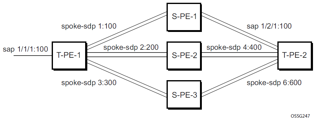
Configuring two VLL paths terminating on T-PE2
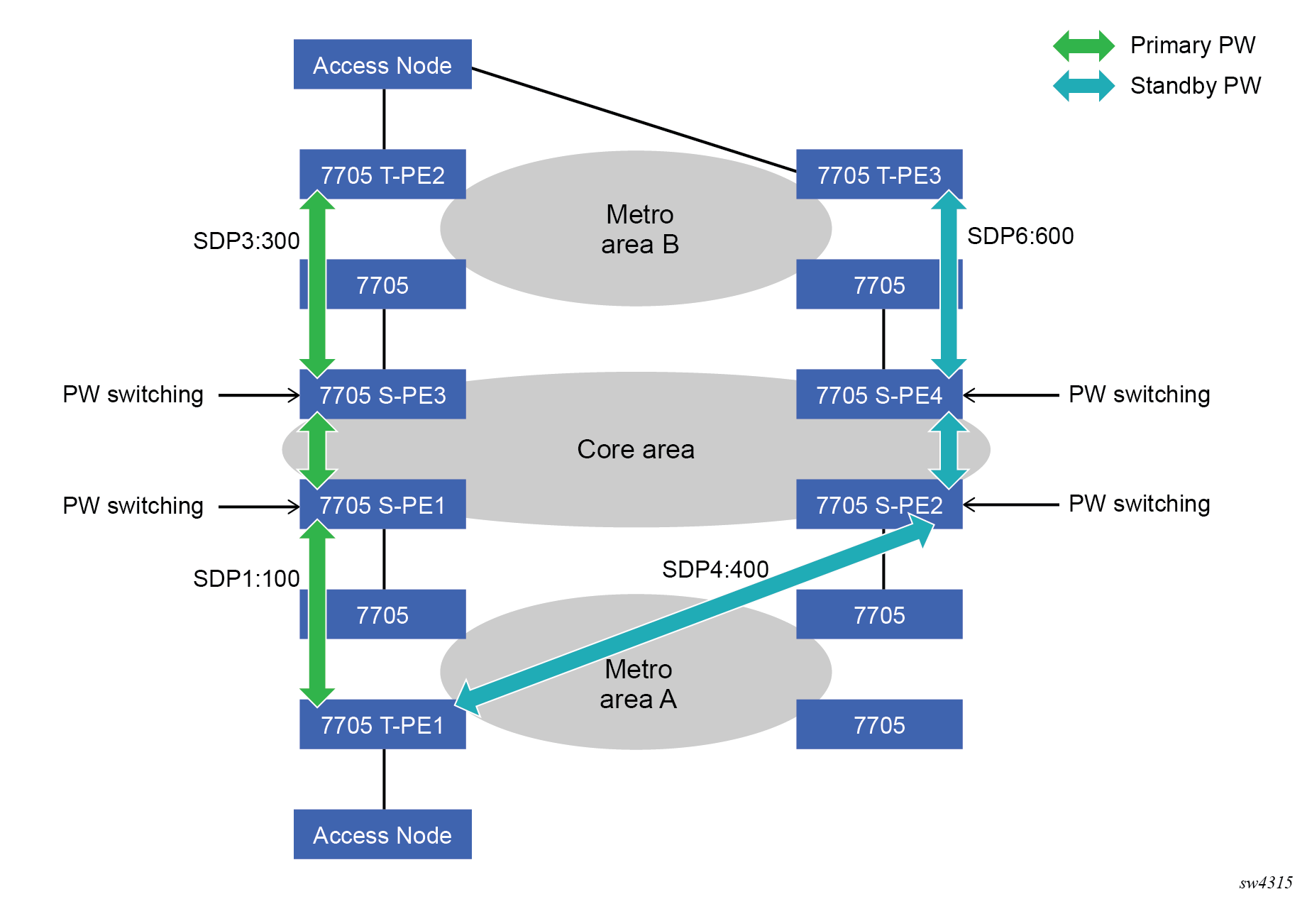
T-PE1
The following shows an example of the T-PE1 configuration:
*A:ALA-T-PE1>config>service>epipe# info
----------------------------------------------
            endpoint "x" create
            exit
            endpoint "y" create
            exit
            spoke-sdp 1:100 endpoint "y" create
                precedence primary
                revert-time 0
            exit
            spoke-sdp 4:400 endpoint "y" create
                precedence 0
            exit
            no shutdown
----------------------------------------------
*A:ALA-T-PE1>config>service>epipe#
T-PE2
The following shows and example of the T-PE2 configuration.
*A:ALA-T-PE2>config>service>epipe# info
----------------------------------------------
            endpoint "x" create
            exit
            endpoint "y" create
            exit
            sap 2/2/2:200 endpoint "x" create
            exit
            spoke-sdp 3:300 endpoint "y" create
                precedence primary
                revert-time 0
            exit
            spoke-sdp 6:600 endpoint "y" create
                precedence 0
            exit
            no shutdown
----------------------------------------------
*A:ALA-T-PE2>config>service>epipe#
S-PE1
Specifying the vc-switching parameter enables a VC cross-connect, so the service manager does not signal the VC label mapping immediately, but puts this into passive mode.
The following example shows the configuration:
*A:ALA-S-PE1>config>service>epipe# info
----------------------------------------------
...
            spoke-sdp 2:200 create
            exit
            spoke-sdp 3:300 create
            exit
            no shutdown
----------------------------------------------
*A:ALA-S-PE1>config>service>epipe#
S-PE2
Specifying the vc-switching parameter enables a VC cross-connect, so the service manager does not signal the VC label mapping immediately, but puts this into passive mode.
The following example shows the configuration:
*A:ALA-S-PE2>config>service>epipe# info
----------------------------------------------
...
            spoke-sdp 2:200 create
            exit
            spoke-sdp 3:300 create
            exit
            no shutdown
----------------------------------------------
*A:ALA-S-PE2>config>service>epipe#
Configuring VLL resilience
The following figure shows an example to create VLL resilience. The zero revert-time value means that the VLL path is switched back to the primary immediately after it comes back up.
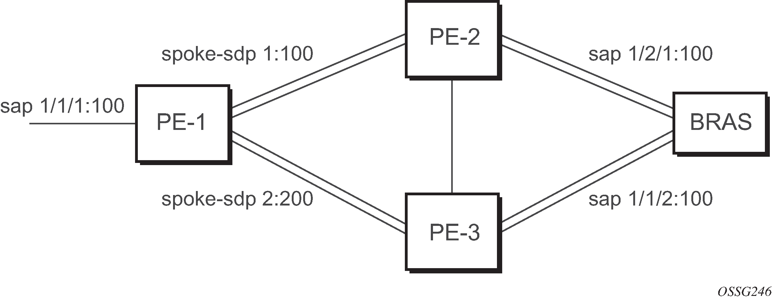
PE-1
The following example shows the configuration on PE-1:
*A:ALA-48>config>service>epipe# info
----------------------------------------------
            endpoint "x" create
            exit
            endpoint "y" create
            exit
            spoke-sdp 1:100 endpoint "y" create
                precedence primary
            exit
            spoke-sdp 2:200 endpoint "y" create
                precedence 1
            exit
            no shutdown
----------------------------------------------
*A:ALA-48>config>service>epipe#
Configuring VLL resilience for a switched pseudowire path
The following figure shows an example of VLL resilience with pseudowire switching.
T-PE-1
The following example shows the configuration on T-PE-1.
*A:ALA-48>config>service>epipe# info
----------------------------------------------
            endpoint "x" create
            exit
            endpoint "y" create
            exit
            sap 1/1/1:100 endpoint "x" create
            exit
            spoke-sdp 1:100 endpoint "y" create
                precedence primary
            exit
            spoke-sdp 2:200 endpoint "y" create
                precedence 1
            exit
            spoke-sdp 3:300 endpoint "y" create
                precedence 1
            exit
            no shutdown
----------------------------------------------
*A:ALA-48>config>service>epipe#
T-PE-2
The following is an example configuration output on T-PE-2.
*A:ALA-49>config>service>epipe# info
----------------------------------------------
            endpoint "x" create
            exit
            endpoint "y" create
                revert-time 100
            exit
            spoke-sdp 4:400 endpoint "y" create
                precedence primary
            exit
            spoke-sdp 5:500 endpoint "y" create
                precedence 1
            exit
            spoke-sdp 6:600 endpoint "y" create
                precedence 1
            exit
            no shutdown
----------------------------------------------
*A:ALA-49>config>service>epipe#
S-PE-1
The following is an example configuration output on S-PE-1.
*A:ALA-50>config>service>epipe# info
----------------------------------------------
...
            spoke-sdp 1:100 create
            exit
            spoke-sdp 4:400 create
            exit
            no shutdown
----------------------------------------------
*A:ALA-49>config>service>epipe#
Configuring BGP VPWS
Single-homed BGP VPWS
The following figure shows an example topology for a BGP VPWS service used to create a VLL across an MPLS network between sites A and B.
An Epipe is configured on PE1 and PE2 with BGP VPWS enabled. PE1 and PE2 are connected to site A and B, respectively, each using a SAP. The interconnection between the two PEs is achieved through a pseudowire, using Ethernet VLAN encapsulation, which is signaled using BGP VPWS over a tunnel LSP between PE1 and PE2. A MIP or MEP can be configured on a BGP VPWS SAP. However, fault propagation between a MEP and the BGP update state signaling is not supported. BGP VPWS routes are accepted only over an IBGP session.
The following examples shows the BGP VPWS configuration on each PE.
PE1 configuration
pw-template 1 create
    vc-type vlan
exit
epipe 1 customer 1 create
    bgp
        route-distinguisher 65536:1
        route-target export target:65536:1 import target:65536:1
        pw-template-binding 1
        exit
    exit
    bgp-vpws
        ve-name PE1
            ve-id 1
        exit
        remote-ve-name PE2
            ve-id 2
        exit
        no shutdown
    exit
    sap 1/1/1:1 create
    exit
    no shutdown
exit
PE2 configuration
pw-template 1 create
    vc-type vlan
exit
epipe 1 customer 1 create
    bgp
        route-distinguisher 65536:2
        route-target export target:65536:1 import target:65536:1
        pw-template-binding 1
        exit
    exit
    bgp-vpws
        ve-name PE2
            ve-id 2
        exit
        remote-ve-name PE1
            ve-id 1
        exit
        no shutdown
    exit
    sap 1/1/1:1 create
    exit
    no shutdown
exit
The BGP-VPWS update can be displayed using the following command:
show service l2-route-table bgp-vpws detail ===============================================================================
Services: L2 Bgp-Vpws Route Information - Summary
===============================================================================
Svc Id : 1
VeId : 2
PW Temp Id : 1
RD : *65536:2
Next Hop : 10.1.1.2
State (D-Bit) : up(0)
Path MTU : 1514
Control Word : 0
Seq Delivery : 0
Status : active
Tx Status : active
CSV : 0
Preference : 0
Sdp Bind Id : 17407:4294967295
===============================================================================
A:PE1#
Dual-homed BGP VPWS
Single pseudowire example:
The following figure shows an example topology for a dual-homed BGP VPWS service used to create a VLL across an MPLS network between sites A and B. A single pseudowire is established between the designated forwarder of the dual-homed PEs and the remote PE.
An Epipe with BGP VPWS enabled is configured on each PE. Site A is dual-homed to PE1 and PE2 with a remote PE (PE3) connected to site B; each connection uses a SAP. A single pseudowire using Ethernet Raw Mode encaps connects PE3 to PE1. The pseudowire is signaled using BGP VPWS over a tunnel LSP between the PEs.
Site A is configured on PE1 and PE2 with the BGP route selection, the site state, and the site-preference used to ensure PE1 is the designated forwarder when the network is fully operational.
The following examples show the BGP VPWS configuration on each PE.
Dual-homed BGP VPWS configuration with single pseudowires on PE1
pw-template 1 create
exit
epipe 1 customer 1 create
    bgp
        route-distinguisher 65536:1
        route-target export target:65536:1 import target:65536:1
        pw-template-binding 1
        exit
    exit
    bgp-vpws
        ve-name PE1
            ve-id 1
        exit
        remote-ve-name PE3
            ve-id 3
        exit
        no shutdown
    exit
    sap 1/1/1:1 create
    exit
    site "siteA" create
        site-id 1
        sap 1/1/1:1
        boot-timer 20
        site-activation-timer 5
        no shutdown
    exit
    no shutdown
exit
Dual-homed BGP VPWS configuration with single pseudowires on PE2
pw-template 1 create
exit
epipe 1 customer 1 create
    bgp
        route-distinguisher 65536:2
        route-target export target:65536:1 import target:65536:1
        pw-template-binding 1
        exit
    exit
    bgp-vpws
        ve-name PE2
            ve-id 1
        exit
        remote-ve-name PE3
            ve-id 3
        exit
        no shutdown
    exit
    sap 1/1/1:1 create
    exit
    site "siteA" create
        site-id 1
        sap 1/1/1:1
        boot-timer 20
        site-activation-timer 5
        no shutdown
    exit
    no shutdown
exit
Dual-homed BGP VPWS configuration with single pseudowires on PE3
pw-template 1 create
exit
epipe 1 customer 1 create
    bgp
        route-distinguisher 65536:3
        route-target export target:65536:1 import target:65536:1
        pw-template-binding 1
        exit
    exit
    bgp-vpws
        ve-name PE3
            ve-id 3
        exit
        remote-ve-name PE1orPE2
            ve-id 1
        exit
        no shutdown
    exit
    sap 1/1/1:1 create
    exit
    no shutdown
exit
Active/standby pseudowire example:
The following figure shows an example topology for a dual-homed BGP VPWS service used to create a VLL across an MPLS network between sites A and B. Two pseudowires are established between the remote PE and the dual-homed PEs. The active pseudowire used for the traffic is the one connecting the remote PE to the designated forwarder of the dual-homed PEs.
An Epipe with BGP VPWS enabled is configured on each PE. Site A is dual-homed to PE1 and PE2 with a remote PE (PE3) connected to site B; each connection uses a SAP. Active/standby pseudowires using Ethernet Raw Mode encapsulation connect PE3 to PE1 and PE2, respectively. The pseudowires are signaled using BGP VPWS over a tunnel LSP between the PEs.
Site A is configured on PE1 and PE2 with the site-preference set to ensure that PE1 is the designated forwarder when the network is fully operational. An endpoint is automatically created on PE3 in which the active/standby pseudowires are created.
The following examples show the BGP VPWS configurations on each PE.
Dual-homed BGP VPWS configuration with active/standby pseudowires on PE1
pw-template 1 create
exit
epipe 1 customer 1 create
    bgp
        route-distinguisher 65536:1
        route-target export target:65536:1 import target:65536:1
        pw-template-binding 1
        exit
    exit
    bgp-vpws
        ve-name PE1
            ve-id 1
        exit
        remote-ve-name PE3
            ve-id 3
        exit
        no shutdown
    exit
    sap 1/1/1:1 create
    exit
    site "siteA" create
        site-id 1
        sap 1/1/1:1
        boot-timer 20
        site-activation-timer 5
        site-preference 200
        no shutdown
    exit
    no shutdown
exit
Dual-homed BGP VPWS configuration with active/standby pseudowires on PE2
pw-template 1 create
exit
epipe 1 customer 1 create
    bgp
        route-distinguisher 65536:2
        route-target export target:65536:1 import target:65536:1
        pw-template-binding 1
        exit
    exit
    bgp-vpws
        ve-name PE2
            ve-id 2
        exit
        remote-ve-name PE3
            ve-id 3
        exit
        no shutdown
    exit
    sap 1/1/1:1 create
    exit
    site "siteA" create
        site-id 1
        sap 1/1/1:1
        boot-timer 20
        site-activation-timer 5
        site-preference 10
        no shutdown
    exit
    no shutdown
exit
Dual-homed BGP VPWS configuration with active/standby pseudowires on PE3
pw-template 1 create
exit
epipe 1 customer 1 create
    bgp
        route-distinguisher 65536:3
        route-target export target:65536:1 import target:65536:1
        pw-template-binding 1
        exit
    exit
    bgp-vpws
        ve-name PE3
            ve-id 3
        exit
        remote-ve-name PE1
            ve-id 1
        exit
        remote-ve-name PE2
            ve-id 2
        exit
        no shutdown
    exit
    sap 1/1/1:1 create
    exit
    no shutdown
exit
Service management tasks
This section describes the VLL service management tasks.
Modifying Epipe service parameters
Use the following syntax to add an accounting policy to an existing SAP.
config>service# epipe 2
config>service>epipe# sap 2/1/3:21
config>service>epipe>sap# accounting-policy 14
config>service>epipe>sap# exit
SAP configuration output
ALA-1>config>service# info
----------------------------------------------
    epipe 2 customer 6 vpn 2 create
            description "Distributed Epipe service to east coast"
            sap 2/1/3:21 create
              accounting-policy 14
            exit
            spoke-sdp 2:6000 create
            exit
            no shutdown
        exit
----------------------------------------------
ALA-1>config>service#
Disabling an Epipe service
Use the following syntax to shut down an Epipe service without deleting the service parameters.
config>service> epipe service-id
    shutdown
config>service# epipe 2
    config>service>epipe# shutdown
    config>service>epipe# exit
Re-enabling an Epipe service
Use the following syntax to re-enable an Epipe service that was shut down.
config>service# epipe service-id
    no shutdown
config>service# epipe 2
    config>service>epipe# no shutdown
    config>service>epipe# exit
Deleting an Epipe service
- Shut down the SAP and SDP.
- Delete the SAP and SDP.
- Shut down the service.
-
Use the following CLI syntax to delete the Epipe service:
config>service
      [no] epipe service-id
          shutdown
          [no] sap sap-id
              shutdown
      [no] spoke-sdp sdp-id:vc-id
              shutdown
config>service# epipe 2
config>service>epipe# sap 2/1/3:21
config>service>epipe>sap# shutdown
config>service>epipe>sap# exit
config>service>epipe# no sap 2/1/3:21
config>service>epipe# spoke-sdp 2:6000
config>service>epipe>spoke-sdp# shutdown
config>service>epipe>spoke-sdp# exit
config>service>epipe# no spoke-sdp 2:6000
config>service>epipe# epipe 2
config>service>epipe# shutdown
config>service>epipe# exit
config>service# no epipe 2