IP tunnels
IP tunnels overview
This section discusses IP Security (IPsec)tunneling features supported by the virtual tunnel ISA. The virtual tunnel ISA functions as a resource module for the system, providing encapsulation and (for IPsec) encryption functions. The IPsec encryption functions provided by the virtual tunnel ISA are applicable for many applications including mobile backhaul, encrypted SDPs, video wholesale, site-to-site encrypted tunnel, and remote access VPN concentration.
7705 SAR Gen 2 IPsec implementation architecture shows an example of an IPsec deployment, and the way this would be supported inside a 7705 SAR Gen 2.
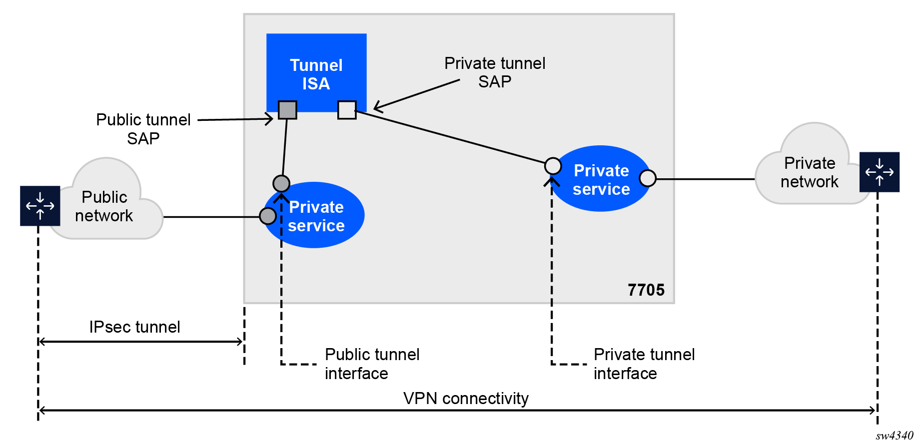
7705 SAR Gen 2 IPsec implementation architecture, the public network is typically an ‟insecure network” (for example, the public Internet) over which packets belonging to the private network in the diagram cannot be transmitted natively. Inside the 7705 SAR Gen 2, a public service instance (IES or VPRN) connects to the public network and a private service instance (typically a VPRN) connects to the private network.
The public and private services are typically two different services, and the ISA is the only ‟bridge” between the two. Traffic from the public network may need to be authenticated and encrypted inside an IPsec tunnel to reach the private network. In this way, the authenticity/confidentiality/integrity of accessing the private network can be enforced.
The ISA provides a variety of encryption features required to establish bidirectional IPsec tunnels including:
control plane
manual keying
dynamic keying: IKEv1/v2
IKEv1 mode: main and aggressive
authentication: Pre-Shared-Key /xauth with RADIUS support/X.509v3 Certificate/EAP
Perfect Forward Secrecy (PFS)
DPD
NAT-Traversal
security policy
DH-Group: 1/2/5/14/15/19/20/21
data plane
ESP (with authentication) tunnel mode
authentication algorithm: MD5/SHA1/SHA256/SHA384/SHA512/AES-XCBC
encryption algorithm: DES/3DES/AES128/AES192/AES256/AES-GCM128/AES-GCM192/AES-GCM256/AES-GMAC128/AES-GMAC192/AES-GMAC256
anti-replay protection
SR OS uses a configured authentication algorithm for the Pseudorandom Function (PRF).
There are two types of tunnel interfaces and SAPs. See Tunnel interfaces and SAPs for more information.
| Tunnel interface/SAP | Association/configuration |
|---|---|
|
Public tunnel interface |
configured in the public service; outgoing tunnel packets have a source IP address in this subnet |
|
Public tunnel SAP |
associated with the public tunnel interface; a logical access point to the ISA card in the public service |
|
Private tunnel interface |
configured in the private service; can be used to define the subnet for remote access IPsec clients |
|
Private tunnel SAP |
associated with the private tunnel interface, a logical access point to the ISA card in the private service |
Traffic flows to and through the ISA card as follows:
upstream direction
The encapsulated (and possibly encrypted) traffic is forwarded to a public tunnel interface if its destination address matches the local or gateway address of an IPsec tunnel or the source address of a GRE or IP-IP tunnel. Inside the ISA card, encrypted traffic is decrypted, the tunnel header is removed, the payload IP packet is delivered to the private service, and from there, the traffic is forwarded again based on the destination address of the payload IP packet.
downstream direction
Unencapsulated/clear traffic belonging to the private service is forwarded into the tunnel by matching a route with the IPsec/GRE/IP-IP tunnel as next-hop. The route can be configured statically, learned by running OSPF on the private tunnel interface (GRE tunnels only), learned by running BGP over the tunnel (IPsec and GRE tunnels only), or learned dynamically during IKE negotiation (IPsec only). After clear traffic is forwarded to the ISA card, it is encrypted if required, encapsulated per the tunnel type, delivered to the public service, and from there, the traffic is forwarded again based on the destination address of the tunnel header.
Tunnel ISAs
A tunnel group is a collection of MS-ISA2s (MDA type isa2-tunnel) or ESA-VM (VM type tunnel) configured to handle the termination of one or more IPsec tunnels.
The following example displays tunnel group configurations.
MD-CLI
[ex:/configure isa]
A:admin@node-2# info
    tunnel-group 1 {
        admin-state enable
        isa-scale-mode tunnel-limit-2k
        primary 1/1
        backup 2/1
        }

    tunnel-group 2 {
        admin-state enable
        multi-active {
            isa 3/1 { }
            isa 3/2 { }
        }

    tunnel-group 3 {
        admin-state enable
        multi-active {
            esa 3 vm 1 { }
            esa 4 vm 1 { }
        }
classic CLI
A:node-2>config>isa# info
----------------------------------------------
	tunnel-group 1 isa-scale-mode tunnel-limit-2k create
            primary 1/1
            backup 1/2
            no shutdown
        exit

        tunnel-group 2 isa-scale-mode tunnel-limit-2k create
 	     multi-active
 	     mda 3/1
 	     mda 3/2
  	    no shutdown
        exit

     tunnel-group 3 create
          multi-active
          esa-vm 3/1
          esa-vm 4/1
          no shutdown
	exit
An IPsec tunnel belongs to only one tunnel group. There are two types of tunnel groups:
-
single-active tunnel group
A single-active tunnel group can have one tunnel-ISA designated as primary and, optionally, one other tunnel-ISA designated as backup. If the primary ISA fails the affected failed tunnels are re-established on the backup (which is effectively a cold standby) if it is not already in use as a backup for another tunnel group.
-
multi-active tunnel group
A multi-active tunnel group can have multiple tunnel-ISAs designated as primary. Only one ISA is supported on the 7705 SAR Gen 2.
The show isa tunnel-group command allows the user to view information about all configured tunnel groups. This command displays the following information for each tunnel group: group ID, active tunnel-ISA, administrative state, and operational state.
There are three thresholds that are used to monitor memory usage in a tunnel-ISA:
-
max-threshold
When the memory usage of an ISA exceeds this threshold, any new IKE states are rejected.
-
high-watermark
When the memory usage of an ISA exceed this threshold, a trap is generated.
-
low-watermark
When the memory usage of an ISA fall below this threshold, a clear trap is generated.
These three thresholds are fixed, not configurable.
A tunnel-group has an isa-scale-mode, which defines the maximum number of all tunnels (all types combined) which can be established on each ISA of the tunnel group. The available tunnel limits vary per platform.
Public tunnel SAPs
A VPRN or IES service (the delivery service) must have at least one IP interface associated with a public tunnel SAP to receive and process the following types of packets associated with IPsec tunnels:
-
IPsec ESP (IP protocol 50)
-
IKE (UDP)
The public tunnel SAP type has the format tunnel-tunnel-group.public:index, as shown in the following CLI example.
MD-CLI
[ex:/configure service]
A:admin@node-2# info
    ies "1" {
        admin-state enable
        customer "1"
        interface "public" {
            tos-marking-state untrusted
            sap tunnel-1.public:200 {
            }
            ipv4 {
                primary {
                    address 192.168.12.1
                    prefix-length 24
                }
            }
        }
    }
   vprn "2" {
        customer "1"
        bgp-ipvpn {
            mpls {
                admin-state enable
                route-distinguisher "10.1.1.1:65007"
            }
        }
       interface "greTunnel" {
            tunnel true
            ipv4 {
                addresses {
                    address 10.0.0.1 {
                        prefix-length 24
                    }
                }
                dhcp {
                    admin-state enable
                }
            }
            sap tunnel-1.private:210 {
                ip-tunnel "toCel" {
                    admin-state enable
                    delivery-service "service1"
                    remote-ip-address 10.251.12.2
                    backup-remote-ip-address 10.251.12.22
                    local-ip-address 192.168.12.100
                    gre-header {
                        admin-state enable
                    }
                    dest-ip 10.0.0.2 { }
                }
            }
        }
    }
classic CLI
A:node-2>config>service# info
----------------------------------------------
        customer 1 create
            description "Default customer"
        exit
        ies 1 customer 1 create
            interface "public" create
                address 192.168.12.1/24
                tos-marking-state untrusted
                sap tunnel-1.public:200 create
                exit
            exit
            no shutdown
        exit
        vprn 2 customer 1 create
            interface "greTunnel" tunnel create
                address 10.0.0.1/24
                dhcp
                    no shutdown
                exit
                sap tunnel-1.private:210 create
                    ip-tunnel "toCel" create
                        dest-ip 10.0.0.2
                        gre-header
                        source 192.168.12.100
                        remote-ip 10.251.12.2
                        backup-remote-ip 10.251.12.22
                        delivery-service 1
                        no shutdown
                    exit
                exit
            exit
            bgp-ipvpn
                mpls
                    route-distinguisher 10.1.1.1:65007
                    no shutdown
                exit
            no shutdown
        exit
Private tunnel SAPs
The private service must have an IP interface to an IPsec tunnel to forward IP packets into the tunnel, causing them to be encapsulated (and possibly encrypted) per the tunnel configuration and to receive IP packets from the tunnel after the encapsulation has been removed (and decryption). That IP interface is associated with a private tunnel SAP.
The private tunnel SAP has the format tunnel-tunnel-group.private:index, as shown in the following CLI example where an IPsec tunnel is configured under the SAP.
Use the following command to see information about an IP tunnel.
show ip tunnel===============================================================================
IP Tunnels
===============================================================================
TunnelName SapId SvcId Admn
Local Address DlvrySvcId Oper
OperRemoteAddress
-------------------------------------------------------------------------------
tun-1-ipsec-tunnel tunnel-1.private:1 201 Up
192.168.1.2 1201 Up
192.168.3.2
-------------------------------------------------------------------------------
IP Tunnels: 1
===============================================================================
IP interface configuration
In the configuration example of the previous section the IP address 10.0.0.1 is the address of the IPsec tunnel endpoint from the perspective of payload IP packets. This address belongs to the address space of the VPRN 1 service and is not exposed to the public IP network carrying the IPsec encapsulated packets. An IP interface associated with a private tunnel SAP does not support unnumbered operation.
It is possible to configure the IP MTU (M) of a private tunnel SAP interface. This sets the maximum payload IP packet size (including IP header) that can be sent into the tunnel, for example, it applies to the packet size before the tunnel encapsulation is added. When a payload IPv4 packet that needs to be forwarded into the tunnel is larger than M bytes the payload packet is IP fragmented (before tunnel encapsulation) if the DF bit is clear, otherwise the packet is discarded. When a payload IPv6 packet that needs to be forwarded into the tunnel is larger than M bytes the packet is discarded if its size is less than 1280 bytes otherwise it is forwarded and encapsulated intact.
IP fragmentation and reassembly for IP tunnels
An IPsec tunnel packet that is larger than the IP MTU of some interface in the public network must either be discarded (if the Do Not Fragment (DF) bit is set in the outer IP header) or fragmented. If the tunnel packet is fragmented, then it is up to the destination tunnel endpoint to reassemble the tunnel packet from its fragments. IP reassembly can be enabled for all the IPsec tunnels belonging to a tunnel group. When reassembly is disabled for a tunnel, all received fragments belonging to the tunnel are dropped.
To avoid public network fragmentation of IPsec packets belonging to a particular tunnel, one possible strategy is to fragment IPv4 payload packets larger than a specified size M at entry into the tunnel (before encapsulation and encryption if applicable). The size M is configurable using the ip-mtu command under the template, service, or router IPsec tunnel contexts.
If the payload IPv4 packets are all M bytes or less in length then it is guaranteed that all resulting tunnel packets are less than M+N bytes in length, if N is the maximum overhead added by the tunneling protocol. If M+N is less than the smallest interface IP MTU in the public network, fragmentation is avoided. In some cases, some of the IPv4 payload packets entering a tunnel may have their DF bit set. And if needed, the SR OS supports the option (also configurable on a per-tunnel basis) to clear the DF bit in these packets so that they can be fragmented.
The system allows users to configure an encapsulated-ip-mtu for a tunnel in the template, service, or router IPsec tunnel contexts. This represents the maximum size of the encapsulated tunnel packet. After encapsulation, If the IPv4 or IPv6 tunnel packet size exceeds the configured encapsulated-ip-mtu, the system fragments the packet against the encapsulated-ip-mtu.
The following is a description of system behavior about fragmentation:
-
private side
If the size, before encapsulation, of the IPv4 or IPv6 packet entering the tunnel is larger than the IP MTU configured for the template, service, or router IPsec tunnel:
-
IPv4 payload packet
If the DF bit is not set in the packet or if the clear-df-bit command is configured, the system fragments the packet against the IP MTU configured in the template, service, or router IPsec tunnel context.
Otherwise, the system drops the packet and sends back an ICMP error Fragmentation required and DF flag set, with the suggested MTU set as the IP MTU.
-
IPv6 payload packet
If the packet size >1280 bytes, the system drops the packet and sends back an ICMPv6 Packet Too Big (PTB) message with the suggested MTU set as the IP MTU.
If the packet size<=1280 bytes, the system forwards the packet into the tunnel.
-
-
public side
This applies to both ESP and IKE packets, IPv4 and IPv6.
If the ESP/IKE packet is larger than the encapsulated-ip-mtu, the system fragments the packet against the encapsulated-ip-mtu; however, when the IPv6 ESP/IKE packet is smaller than 1280 bytes, the system does not fragment it, even if it is larger than the encapsulated-ip-mtu.
TCP MSS adjustment
The system supports the Transmission Control Protocol (TCP) Maximum Segment Size (MSS) adjustment feature for the following types of tunnels on the ISA:
-
IPsec
The intent of TCP MSS adjustment is to avoid IP-level fragmentation for TCP traffic encapsulated in a tunnel by updating the MSS option value in the TCP SYN packet with an appropriate value. This feature is useful when there is tunnel encapsulation that is not known by a TCP host, and the extra tunnel encapsulation overhead may cause IP-level fragmentation.
The system supports TCP MSS adjustment on both the public and private sides.
On the public side, when the ISA receives a tunnel packet (such as ESP), after decryption or decapsulation, if the payload packet is a TCP SYN packet, then the ISA replaces the MSS option with a configured value if the configured MSS value is smaller than the received MSS value or when there is no MSS option:
-
If public-tcp-mss-adjust auto is configured, then:
new MSS value =public_side_MTU – tunnel_overhead – TCP fixed header – IP fixed header
where:
-
public_side_MTU = encapsulated-ip-mtu
If encapsulated-ip-mtu is not configured, which means there is no post-encap fragmentation on ISA, then TCP MSS adjust is disabled.
-
TCP fixed header = 20
-
IP fixed header = 20 (Ipv4) or 40 (IPv6)
-
-
If a specific MSS value for the public-tcp-mss-adjust is configured, the new MSS value is set to the public-tcp-mss-adjust value.
-
The public-tcp-mss-adjust auto command only applies to IPsec and IPinIP/GRE tunnels.
-
For an IPsec tunnel, the tunnel_overhead is the maximum overhead of the corresponding CHILD_SA.
-
For an IPinIP tunnel, the tunnel_overhead is 0.
-
For a GRE tunnel, the tunnel_overhead is length of GRE header.
The private side is similar to the public side. The system processes the received TCP SYN packet on the private side if the TCP MSS adjust is enabled. However, there is no auto parameter for private-tcp-mss-adjust command.
MTU propagation
MTU propagation is an optional feature that allows the system to listen for fragmentation-related ICMP error message received from the public side of the tunnel. These error messages include:
ICMP Destination Unreachable message "fragmentation needed and DF set" (type 3, code 4)
ICMPv6 Packet Too Big message (type 2)
The suggested MTU value in the ICMP message is used to derive two MTU values:
Temporary public MTU (TMTU) are determined as follows:
The TMTU starts with a configured encapsulated-ip-mtu value.
If the received MTU is less than 1280 and it is from an ICMPv6 packet, the received value is ignored.
If the received MTU is less than 512 and it is from an ICMP packet, the received value is ignored.
If the received MTU is greater than or equal to the configured encapsulated-ip-mtu value, the received value is ignored.
If the received MTU is greater than or equal to the current TMTU, the received value is ignored.
If the received MTU is less than the current TMTU, it replaces the current TMTU.
To prevent attack and rapid change, there is a damp time of 60 seconds after a new TMTU value is set. Within that time frame, all received MTU values are ignored.
TMTU has a lifetime timer (configurable with an aging interval). When the lifetime timer expires, the TMTU’s value is reset to the encapsulated-ip-mtu value. The lifetime timer resets whenever a new TMTU value is set.
TMTU is a per tunnel value.
Temporary private MTU (TPMTU) equals TMTU – Tunnel_Encap_Overhead.
TPMTU is a per CHILD_SA value.
-
Tunnel_Encap_Overhead is a fixed value for a non-IPsec tunnel-per-tunnel type. For an IPsec tunnel, its value is the maximum overhead based on the value used by the CHILD_SA set using the following command:
- MD-CLI
configure ipsec ipsec-transform id - classic
CLI
configure ipsec ipsec-transform
- MD-CLI
TMTU and TPMTU are used in the following cases:
TPMTU is used for fragmenting IP packets received on the private side instead of the configured IP MTU.
IKEv2 message fragmentation uses TMTU instead of the configured encapsulated-ip-mtu.
IKE IP packet fragmentation uses TMTU instead of the configured encapsulated-ip-mtu.
To derive the TCP MSS value for the TCP MSS adjustment, instead of configured encapsulated-ip-mtu.
ESP packet fragmentation (post-encapsulation fragmentation) does not use TMTU; it only uses the configured encapsulated-ip-mtu value.
To enable this feature, configure the propagate-pmtu-v4 and propagate-pmtu-v6 commands in the template, service, or router IPsec tunnel contexts.
IPsec tunnel types
- LAN-to-LAN tunnel (L2L):
- static LAN-to-LAN (SL2L)
- dynamic LAN-to-LAN (DL2L)
- remote-access tunnel (RA)
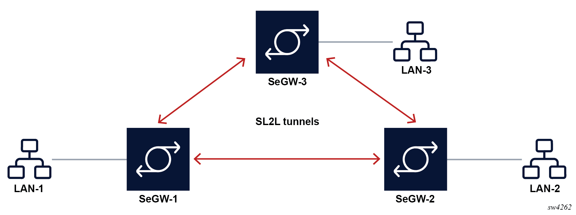
The following features and restrictions apply to SL2L tunnels:
- Per-tunnel configuration is supported, which allows each tunnel to be explicitly configured.
- Each tunnel can be used as the next hop in static routes (directly) or BGP (indirectly).
- SL2L tunnels can act as either the tunnel initiator or responder.
- SL2L tunnels support PSK or certificate-based authentication (or PSK only, in the case of IKEv1).
DL2L tunnels are also used for LAN interconnection. Typically, they are used in a hub-spoke topology where a DL2L tunnel is used on the hub site and the SL2L tunnels are used on the spoke sites. The following figure shows a DL2L tunnel in a hub-spoke topology.
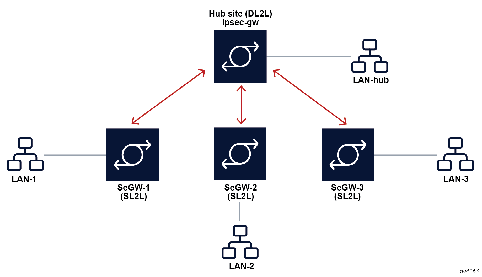
The following features and restrictions apply to DL2L tunnels:
- Per-tunnel configuration is not supported; configuration is per-IPsec gateway only.
- A DL2L tunnel is created dynamically when the IPsec gateway receives an incoming tunnel creation request.
- Reverse routes are created dynamically in a private VRF based on the negotiated TSi to route clear traffic into the tunnel.
- DL2L tunnels can only act as the tunnel responder.
- DL2L tunnels support PSK or certificate-based authentication (or PSK only, in the case of IKEv1)
RA tunnels are typically used by end-user devices to securely access the private network, for example, in the road-warrior VPN use case. The following figure shows an RA tunnel used to access a private network.
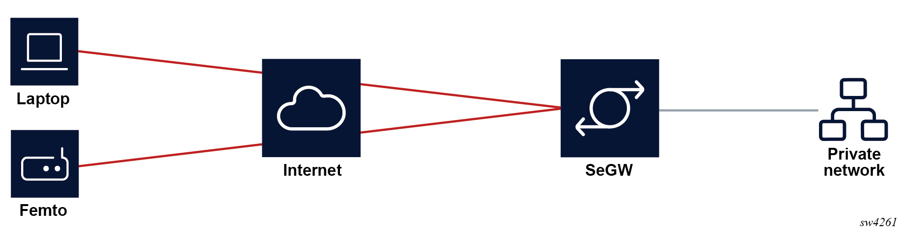
The following features and restrictions apply to RA tunnels:
- Similar to DL2L, configuration for RA tunnels is per-IPsec gateway only.
- An RA tunnel is created dynamically upon receiving a tunnel creation request from the IPsec client.
- The RA tunnel client requests an internal IP address assignment from the SeGW during tunnel creation. These addresses are used as the source address of the private traffic sent by client. Other optional information, such as the DNS server address, can also be returned by the SeGW.
- RA tunnels support the following authentication options:
- PSK (optionally with RADIUS)
- certificate-based authentication (optionally with RADIUS)
- EAP with RADIUS
-
RA tunnels support optional RADIUS accounting
Operational conditions
A tunnel group that is in use cannot be deleted. In single-active mode, changes to the primary ISA are allowed only when the tunnel group is in a shutdown state.
Changes can be made to the following:
-
enabling or disabling the following configuration
configure isa tunnel-group ipsec-responder-only
The public interface address can be changed at any time; however, if changed, any static tunnels that were configured to use the public interface address require a configuration changes accordingly. Otherwise, the tunnels are in an operationally down state until their configuration is corrected. The public service cannot be deleted while tunnels are associated.
A tunnel group ID or tag cannot be changed. To remove a tunnel-group instance, it must be in a shutdown state and all IPsec tunnels and IPsec gateways that terminated on the tunnel group must be removed first.
The security policy cannot be changed while an IPsec tunnel is administratively up and using the security policy.
The tunnel local gateway address, peer address, local ID, and public or private service ID parameters cannot be changed while the IPsec gateway or IPsec tunnel is administratively up.
Each IPsec gateway or IPsec tunnel has an administrative state. When the administrative state is down, tunnels cannot be set up.
Each IPsec gateway and IPsec tunnel has an operation state. The operational state can have three possible values:
-
oper-up
All configuration and related information are valid and fully ready for tunnel setup.
-
oper-down
Some critical configuration information is missing or not ready. Tunnels cannot be set up.
-
limited
Not all configuration information is ready to become fully operationally up. When IPsec gateway is in a limited state, it is possible that a new tunnel cannot be established. When the IPsec tunnel is in a limited state, reconnection may fail.
When an IPsec gateway or IPsec tunnel transitions from operationally up to an operationally limited state directly as a result of a hot (non-service affecting) configuration change, established tunnels are not impacted. However, if the IPsec gateway or IPsec tunnel transitions to an operationally down state before it is operationally limited as a result of a service-affecting configuration change, then established tunnels are removed. All operational state transitions are logged.
IPsec gateways or IPsec tunnels can enter the limited state because of the following reasons, among others:
-
A Certificate Authority (CA) profile in the configured trust-anchor-profile goes down after the IPsec gateway or IPsec tunnel becomes operationally up.
-
An entry in a configured certificate profile goes down after the IPsec gateway or IPsec tunnel becomes operationally up.
Dynamic configuration change support for IPsec gateway
All dynamic IPsec tunnels (dynamic LAN-to-LAN tunnels and remote-access tunnels) that terminate on the same IPsec gateway share the same configuration. Use the respective commands in the following contexts to configure an IPsec gateway for an IES or VPRN service:
-
MD-CLI
configure service ies interface sap ipsec-gateway configure service vprn interface sap ipsec-gateway -
classic CLI
configure service ies interface sap ipsec-gw
configure service vprn interface sap ipsec-gw
SR OS provides dynamic configuration change capability to modify specific IPsec gateway configurations without impacting existing tunnels.
The following IPsec gateway configurations are dynamically configurable without shutting down the IPsec gateway:
Changing the pre-shared key, using the following commands:
-
MD-CLI
configure service ies interface sap ipsec-gateway pre-shared-key configure service vprn interface sap ipsec-gateway pre-shared-key -
classic CLI
configure service ies interface sap ipsec-gw pre-shared-key
configure service vprn interface sap ipsec-gw pre-shared-key
-
Changing the reference of the IKE policy, using the following commands:
-
MD-CLI
configure service ies interface sap ipsec-gateway ike-policy configure service vprn interface sap ipsec-gateway ike-policy -
classic CLI
configure service ies interface sap ipsec-gw ike-policy
configure service vprn interface sap ipsec-gw ike-policy
-
Changing the reference of the tunnel template, using the following commands:
-
MD-CLI
configure service ies interface sap ipsec-gateway default-tunnel-template configure service vprn interface sap ipsec-gateway default-tunnel-template -
classic CLI
configure service ies interface sap ipsec-gw default-tunnel-template
configure service vprn interface sap ipsec-gw default-tunnel-template
-
Enabling or changing reference of the RADIUS authentication policy, using the following commands:
-
MD-CLI
configure service ies interface sap ipsec-gateway radius authentication-policy configure service vprn interface sap ipsec-gateway radius authentication-policy -
classic CLI
configure service ies interface sap ipsec-gw radius-authentication-policy
configure service vprn interface sap ipsec-gw radius-authentication-policy
-
Enabling or changing the reference of the RADIUS accounting policy, using the following commands:
-
MD-CLI
configure service ies interface sap ipsec-gateway radius accounting-policy configure service vprn interface sap ipsec-gateway radius accounting-policy -
classic CLI
configure service ies interface sap ipsec-gw radius-accounting-policy
configure service vprn interface sap ipsec-gw radius-accounting-policy
-
Enabling, disabling, or changing reference of the TS negotiation, using the following commands:
-
MD-CLI
configure service ies interface sap ipsec-gateway ts-list configure service vprn interface sap ipsec-gateway ts-list -
classic CLI
configure service ies interface sap ipsec-gw ts-negotiation
configure service vprn interface sap ipsec-gw ts-negotiation
-
Enabling, disabling, or changing reference of the client database, using the command options in the following contexts:
-
MD-CLI
configure service ies interface sap ipsec-gateway client-db configure service vprn interface sap ipsec-gateway client-db -
classic CLI
configure service ies interface sap ipsec-gw client-db
configure service vprn interface sap ipsec-gw client-db
-
Changing the certificate configuration, using the commands in the following contexts:
-
MD-CLI
configure service ies interface sap ipsec-gateway cert configure service vprn interface sap ipsec-gateway cert -
classic CLI
configure service ies interface sap ipsec-gw cert
configure service vprn interface sap ipsec-gw cert
-
Changing DHCPv4-based address assignments, using the commands in the following contexts:
-
MD-CLI
configure service ies interface sap ipsec-gateway dhcp-address-assignment dhcpv4 configure service vprn interface sap ipsec-gateway dhcp-address-assignment dhcpv4 -
classic CLI
configure service ies interface sap ipsec-gw dhcp
configure service vprn interface sap ipsec-gw dhcp
-
Changing DHCPv6-based address assignments, using the commands in the following contexts:
-
MD-CLI
configure service ies interface sap ipsec-gateway dhcp-address-assignment dhcpv6 configure service vprn interface sap ipsec-gateway dhcp-address-assignment dhcpv6 -
classic CLI
configure service ies interface sap ipsec-gw dhcp6
configure service vprn interface sap ipsec-gw dhcp6
-
Changing local address assignment configuration, using the commands in the following contexts:
-
MD-CLI
configure service ies interface sap ipsec-gateway local address-assignment configure service vprn interface sap ipsec-gateway local address-assignment -
classic CLI
configure service ies interface sap ipsec-gw local-address-assignment
configure service vprn interface sap ipsec-gw local-address-assignment
-
Existing tunnels are not impacted by dynamic configuration changes. The system uses new configurations for new tunnel negotiations. The system continues to use previous configurations that created the tunnels for ongoing operations (such as rekeying) of the existing tunnel.
OAM interactions
The ISA is IP-addressed by an operator-controlled IP on the public side. That IP address can be used in ping and traceroute commands and the ISA can either respond or forward the packets to the CPM.
For static LAN-to-LAN tunnels, in multi-active mode, ping requests to public tunnel addresses are not answered if the source address is different from the remote address of the static tunnel.
The private side IP address is visible. The status of the interfaces and the tunnels can be viewed using show commands.
Traffic that ingresses or egresses an IES or VPRN service associated with specific IPsec tunnels can be mirrored like other traffic.
Mirroring is allowed per interface (public) or IPsec interface (private) side. A filter mirror is allowed for more specific mirroring.
Redundancy
IPsec supports dead peer detection (DPD).
Statistics collection
Input and output octets and packets per service queue are used for billing end customers who are on a metered service plan. Because multiple tunnels can be configured per interface, the statistics can include multiple tunnels. These can be viewed in the CLI and SNMP.
Reporting (syslog, traps) for authentication failures and other IPsec errors are supported, including errors during IKE processing for session setup and errors during encryption or decryption.
A session log indicates the sort of SA setup when there is a possible negotiation. This includes the setup time, teardown time, and negotiated parameters (such as encryption algorithm) as well as identifying the service a particular session is mapped to, and the user associated with the session.
Security
The ISA module provides security utilities for IPsec-related service entities that are assigned to interfaces and SAPs. These entities (such as card, virtual MS-ISA, and IES or VPRN services) must be enabled in order for the security services to process. The module only listens to requests for security services from configured remote endpoints. In the case of a VPN concentrator application, these remote endpoints could come from anywhere on the Internet. In the cases where a point-to-point tunnel is configured, the module listens only to messages from that endpoint.
IKEv2
IKEv2, defined in RFC 4306, Internet Key Exchange (IKEv2) Protocol, is the second version of the Internet Key Exchange Protocol. The main driver of IKEv2 is to simplify and optimize IKEv1. An IKE_SA and a CHILD_SA can be created with only four IKEv2 message exchanges. IKEv2 is supported with the following features:
-
static LAN-to-LAN tunnel
-
dynamic LAN-to-LAN tunnel
-
remote-access tunnel
-
pre-shared-key authentication, certificate authentication, EAP (remote-access tunnel only)
-
liveness check
-
IKE_SA rekey
-
CHILD_SA rekey (full Traffic-Selector support including protocol and port range)
-
extended ESP sequence number
IKEv2 traffic selector and TS-list
The SR OS IKEv2 implementation supports the following traffic selectors:
-
IPv4/IPv6 address range
-
IP protocol ID
-
protocol port range
Port range (including OPAQUE ports) is supported for the following protocols:
-
TCP
-
UDP
-
SCTP
-
ICMP
-
ICMPv6
-
MIPv6
With ICMP and ICMPv6, the system treats the most significant 8 bits of the IKEv2 TS port value as the ICMP message type and the least significant 8 bits as ICMP code.
With MIPv6, the system treats the most significant 8 bits of the IKEv2 TS port value as the mobility header type.
With ICMP, ICMPv6, and MIPv6, the port value in TSi is the value that the tunnel initiator can send, and the port value in TSr is the value that the tunnel responder can send.
The SR OS supports OPAQUE as a TS port selector. An OPAQUE port means that the corresponding CHILD_SA only accepts packets that are supposed to have port information but do not, such as when a packet is a non-initial fragment.
The system allows users to configure a TS-list for each IPsec gateway, applied to both IKEv2 remote access tunnels and dynamic LAN-to-LAN tunnels. Each TS-list contains a local part and a remote part, with each part containing up to 32 entries. Each entry can contain address ranges or subnets, protocols, and port range configurations.
The local part of the TS-list represents the traffic selector for the local system, while the remote part is for the remote peer. If a TS-list is applied on an IPsec gateway, and the system is the tunnel responder, then the local part is TSr and the remote part is TSi.
Combinations of address range, protocol, and port range are not allowed to overlap between entries in the same TS-list.
The system performs traffic selector narrowing as follows.
-
For each TS in the received TSi/TSr, independent address, protocol, and port narrowing is performed. The resulting TS-set is the combination of the address, protocol, and range intersections.
-
The collected TS-set is used as the TSi/TSr.
For a remote access tunnel, TSi narrowing results in an intersection between the following three TSis:
-
the TSi received from the client
-
the remote part configuration of the TS-list
-
a generated TS based on the assigned internal address
-
address (the assigned internal address)
-
protocol (any)
-
port range (any)
-
The following is an example of a dynamic LAN-to-LAN tunnel.
The configured TS-list local part is as follows:
-
Entry 1: 10.10.1.0 → 10.10.1.20, udp, port 100 → 200
-
Entry 2: 10.20.1.0 → 10.20.1.20, udp, port 300 → 400
The peer proposes the following TSr:
-
Entry 1: 10.10.1.1 → 10.10.1.5, udp, port 110 → 150
-
Entry 2: 10.10.1.6 → 10.10.1.10, udp, port 180 → 210
-
Entry 3: 10.10.1.15 → 10.10.1.28, udp, port 120 → 160
-
Entry 4: 10.20.1.15 → 10.20.1.28, tcp, port 250 → 450
The intersections for the proposed entries are as follows:
-
Entry 1: 10.10.1.1 → 10.10.1.5, udp, port 110 → 150
-
Entry 2: 10.10.1.6 → 10.10.1.10, udp, port 180 → 200
-
Entry 3: 10.10.1.15 → 10.10.1.20, udp, port 120 → 160
-
Entry 4: 10.20.1.15 → 10.20.1.20, tcp, port 300 → 400
The resulting TSr system return would be:
-
10.10.1.1 → 10.10.1.5, udp, port 110 → 150
-
10.10.1.6 → 10.10.1.10, udp, port 180 → 200
-
10.10.1.15 → 10.10.1.20, udp, port 120 → 160
-
20.20.1.15 → 20.20.1.20, tcp, port 300 → 400
If more than 32 entries are returned, the system rejects the ts-negotiation and returns TS_UNACCEPTABLE to the peer.
For dynamic LAN-to-LAN tunnels, the system can automatically create a reverse route in a private VRF to route clear traffic into the tunnel. The reverse route is created based on the address range part of the narrowed TSi of the CHILD_SA. If there are multiple TSs in the TSi that have overlapping address ranges, the system creates one or more minimal subnet routes that can cover all address ranges in the TSi. If the auto-created reverse route overlaps with an existing reverse route that points to the same tunnel, the system chooses the route with the larger subnet. If the existing route points to a different tunnel, then CHILD_SA creation fails.
For RADIUS authentication options, such as psk-radius, cert-radius, or eap, the RADIUS server can optionally return a TS-list name via the VSA Alc-IPsec-Ts-Override in the access-accept message, which overrides the TS-list name configured via the CLI.
In the event of a CHILD_SA rekey, if the system is a rekey initiator, it sends the current in-use TS to the peer and expect the peer to return the same TS. If the system is a rekey responder, the system does the same narrowing as was done during CHILD_SA creation.
Configuration of a TS-list can be changed without shutting down the IPsec gateway, although the new TS-list only applies to the subsequent rekey or to the new CHILD_SA creation, and does not affect established CHILD_SAs.
IKEv2 fragmentation
In some cases, an IKEv2 message can large, like an IKE_AUTH message with certificate payload. This is likely to cause the IKEv2 packet to be fragmented into a few smaller IP packets. However, in some deployments, there could be devices or network policing, rate limiting or even dropping UDP fragments. In these cases, the SR OS supports fragmenting IKEv2 messages on the protocol level, as specified in RFC 7383, Internet Key Exchange Protocol Version 2 (IKEv2) Message Fragmentation.
This feature is enabled by configuring the an MTU using the following command:
- MD-CLI
configure ipsec ike-policy ike-version-2 ikev2-fragment mtu - classic
CLI
configure ipsec ike-policy ikev2-fragment
The specified MTU is the maximum size of IKEv2 packet.
The system only enables IKEv2 fragmentation for a specific tunnel when the ikev2-fragment is configured and the peer also announces its support via sending a IKEV2_FRAGMENTATION_SUPPORTED notification.
SHA2 support
According to RFC 4868, Using HMAC-SHA-256, HMAC-SHA-384, and HMAC-SHA-512 with IPsec, the following SHA2 variants are supported for authentication or pseudo-random functions:
Use HMAC-SHA-256+ algorithms for data origin authentication and integrity verification in IKEv1/2, ESP:
AUTH_HMAC_SHA2_256_128
AUTH_HMAC_SHA2_384_192
AUTH_HMAC_SHA2_512_256
For use of HMAC-SHA-256+ as a PRF in IKEv1/2:
PRF_HMAC_SHA2_256
PRF_HMAC_SHA2_384
PRF_HMAC_SHA2_512
IPsec client lockout
An optional lockout mechanism can be enabled to block malicious clients and prevent them from using invalid credentials to consume system resources, as well as to prevent malicious users from guessing credentials such as a pre-shared key. This mechanism can be enabled by using the lockout command.
If the number of failed authentication attempts from a particular IPsec client exceeds a configured threshold during a specified time interval, the client is blocked for a configurable period of time. If a client is blocked, the system drops all IKE packets from the source IP address and port.
The following authentication failures are counted as failed authentication attempts:
IKEv1
psk: failed to verify the HASH_I payload in main mode
plain-psk-xauth:
failed to verify the HASH_I payload in main mode
RADIUS access-reject received
IKEv2
psk: failed to verify the AUTH payload in the auth-request packet
psk-radius:
failed to verify the AUTH payload in the auth-request packet
RADIUS access-reject received
cert:
failed to verify the AUTH payload in the auth-request packet
failed to verify the peer’s certification to configured trust-anchors
cert-radius:
failed to verify the AUTH payload in the auth-request packet
failed to verify the peer’s certification to configured trust-anchors
RADIUS access-reject received
eap: RADIUS access-reject received
Other failures, such as being unable to assign an address, are not counted.
The AUTH failure counter is reset by either a successful authentication before the client is blocked, the expiration of a block timer, or the expiration of the duration timer.
If multiple IPsec clients behind a NAT device share the same public IP address, a limit for the maximum number of clients or ports behind the same IP address can be configured. If the number of ports exceeds the configured limitation, all ports from that IP address are blocked.
The clear ipsec lockout command can also be used to manually clear a lockout state for the specified clients.
IPsec tunnel CHILD_SA rekey
SR OS supports CHILD_SA rekeying for both IKEv1 and IKEv2. The following are the behaviors for the rekey:
IKEv1 or IKEv2 CHILD_SA rekey initiator
outbound
The system immediately switches to the new security association (SA) after a new SA is created.
-
inbound
The old SA is kept for three minutes after the new SA is created. Then, it is removed, and upon removal:
-
IKEv1
The system does not send a delete message upon removal.
-
IKEv2
The systems send a delete message upon removal.
-
IKEv1or IKEv2 CHILD_SA rekey responder
outbound
The system keeps using the old SA for 25 seconds after the new SA is created before switching to the new SA. If a delete message of the old SA is received before 25 seconds, the system removes the old SA and starts using new SA.
-
inbound
The old SA is kept for rest of its lifetime. However, if a delete message is received to close the corresponding outbound SA, then the system removes the corresponding inbound SA before its lifetime expires. The system sends a delete message when the old SA lifetime expires.
If the old SA lifetime expires before the 25 seconds or three minutes mentioned above, the old SA is removed upon expiration and the system sends a delete message.
Multiple IKE/ESP transform support
For IPsec tunnels or IPsec gateways, the SR OS allows users to configure up to four IKE transform and four IPsec transform configurations for IKE and ESP traffic.
- MD-CLI
configure service vprn interface sap ipsec-tunnel key-exchange dynamic - classic
CLI
configure service vprn interface sap ipsec-tunnel dynamic-keying
IKE transform includes the following configurations:
-
IKE encryption algorithm
-
IKE authentication algorithm
-
Diffie-Hellman group
-
IKE SA lifetime
IPsec transform includes the following configurations:
-
ESP encryption algorithm
-
ESP authentication algorithm
-
Diffie-Hellman group for CHILD SA rekey with PFS
-
CHILD SA lifetime
If multiple IKE and IPsec transform parameters are configured for IPsec gateways and IPsec tunnels, the system uses the configured transforms to negotiate with the peer. This negotiation allows IPsec gateways and IPsec tunnels to support peers with different crypto algorithms.
Reverse routes for dynamic LAN-to-LAN IPsec tunnels
With dynamic LAN-to-LAN IPsec tunnels, one or multiple reverse routes can be automatically created per CHILD_SA in a private service, based on traffic selectors in the negotiated TSi. Use the following command to enable the creation of reverse routes.
configure ipsec tunnel-template sp-reverse-routeFor a specific CHILD_SA, its TSi contains one or multiple address ranges. The system creates one or multiple reverse routes with the largest prefix length to cover all the ranges in the TSi. If a resulting route overlaps with an existing route of the same tunnel, only the route with the smaller prefix length is kept. If a resulting reverse route is a default route, it is ignored if the ignore-default-route command option is enabled in the tunnel template.
Use the following command to configure the acceptance of overlapping DL2L reverse routes.
configure service vprn ipsec overlapping-reverse-routeIf a reverse route of an in-setup CHILD_SA overlaps with an existing reverse route from a different tunnel, the system handles it according to following command configurations:
- If the overlapping-reverse-route command is configured as false
(disabled):
- If the allow-reverse-route-override-type command (allow-reverse-route-override in classic CLI) is not configured, the in-setup SA fails, resulting in the removal of its tunnel.
- If allow-reverse-route-override-type is configured to same-idi and the in-setup SA belongs to a tunnel that has the same IKEv2 IDi as the corresponding tunnel of the existing reverse route, the system removes the existing tunnel (which includes the existing SA and all others belonging to that tunnel) and creates the in-setup SA; otherwise, the in-setup SA fails.
- If allow-reverse-route-override-type is configured to any-idi, the system removes the existing tunnel (with the existing SA and all other SAs belonging to it) and creates the in-setup SA.
- If the overlapping-reverse-route command is configured as true
(enabled), the system creates the in-setup SA and also keeps the existing SA. The system
installs all overlapping-but-not-same routes in the route table with their associated metric
and preference values configured for the reverse-route command in the
tunnel template. If there are same routes from different tunnels, the system selects the
route to install based on the following rules:
- The lower preference route is preferred.
- The lower metric route is preferred.
- The non-shunting next hop is preferred.
- The routes to install are selected from the set of routes where conditions a, b, and c are equal. The quantity of routes to install is the quantity of ECMP next hops specified by the ECMP configuration of the private service (implicitly 1 when ECMP is disabled in the private service). The routes are selected from the set in order of the lowest values returned by the strcmp() function comparing their next-hop strings.
Using certificates for IPsec tunnel authentication
SR OS supports X.509v3 certificate authentication for IKEv2 tunnel (LAN-to-LAN tunnel and remote-access tunnel). SR OS also supports asymmetric authentication. This means the SR OS and the IKEv2 peer can use different methods to authenticate. For example, one side could use pre-shared key and the other side could use a certificate.
SR OS supports certificate chain verification. For a static LAN-to-LAN tunnel or IPsec gateway, there is a configurable trust-anchor-profile which specifies the expecting CAs that should be present in the certificate chain before reaching the root CA (self-signed CA) configured in the system.
The SR OS’s own key and certificate are also configurable per tunnel or IPsec gateway.
When using certificate authentication, the SR OS uses the subject of the configured certificate as its ID by default.
IKEv2 digital signature authentication
RFC 7427 Signature Authentication in the Internet Key Exchange Version 2 (IKEv2) defines a new IKEv2 AUTH payload method which not only indicates the type of public key, but also the hash algorithm that used to generate the signature; it also includes a new IKEv2 notification: SIGNATURE_HASH_ALGORITHMS, which is used to signal support of RFC 7427 and a list of support hash algorithms to a peer.
RFC 7427 is the default way to perform certificate authentication for IKEv2. The system negotiates its support with the peer as follows:
-
sending
-
as tunnel initiator, includes SIGNATURE_HASH_ALGORITHMS in the IKE_SA_INIT request.
-
as tunnel responder, includes SIGNATURE_HASH_ALGORITHMS in IKE_SA_INIT response only if the received IKE_SA_INIT request includes it.
-
includes the SHA1/SHA2-256/SHA2-384/SHA2-512 hash algorithms in SIGNATURE_HASH_ALGORITHMS
-
-
receiving
-
If the peer does not include SIGNATURE_HASH_ALGORITHMS in the IKE_SA_INIT packet, then it does not support RFC 7427 and the system uses an RSA Digital Signature for the RSA key(value 1), and DSS Digital Signature (value 3) for the DSA key to generate the AUTH payload.
Note: If the ECDSA key is selected in the cert-profile entry, then the tunnel setup fails in the system. -
If the peer sends SIGNATURE_HASH_ALGORITHMS, then the system uses RFC 7427 and the strongest hash algorithms that is supported by both sides to generate the AUTH payload. If there is no common hash algorithms supported by both sides, the system falls back to RSA Digital Signature (Auth Method value 1) or DSS Digital Signature (Auth Method value 3).
Note: If the selected key is an RSA key, there are specific cases that have a short RSA key with long hash algorithm. The system falls back to RSA Digital Signature for RSA key (value 1) even when both sides send SIGNATURE_HASH_ALGORITHMS and there are common hash algorithms.To verify the received digital signature of the AUTH payload, the peer must uses one of the algorithms in the SIGNATURE_HASH_ALGORITHMS that the system sends. Otherwise, the tunnel setup fails.
-
The system continues to use CAs in received cert-request payloads to select the cert-profile entry; if the selected entry is an RSA key, the system needs to decide to whether use PKCS#1-1.5 or RSASS-PSS to generate the signature by using the value set by the following command.
configure ipsec cert-profile entry rsa-signatureTrust-anchor profile
SR OS supports multiple trust-anchors per IPsec tunnel or gateway. Users can configure a trust-anchor-profile that includes up to eight CAs. The system builds a certificate chain by using the certificate in the first certificate payload in the received IKEv2 message. If any of configured trust-anchor CAs in the trust-anchor-profile appears in the chain, then authentication is successful. Otherwise, authentication is failed.
SR OS only supports processing of up to 16 hashes for the trust-anchor list from other products. If the remote end is sending more than 16, and a certificate match is in the > 16 range, the tunnel remains down with authentication failure.
Cert-profile
SR OS supports sending different certificate/chain according to the received IKEv2 certificate-request payload. This is achieved by configuring a cert-profile, which allows up to eight entries. Each entry includes a certificate and a key and, optionally, also a chain of CA certificates.
The system loads the cert and key configured in a cert-profile into memory and builds a chain. Compare-chain is performed for the certificate configured in each entry of the cert-profile upon enabling of the cert-profile. These chains are used in IKEv2 certificate authentication. If a chain computation cannot be completed for a configured certificate, then the corresponding compare-chain is empty or only partially computed.
Because there can be multiple entries configured in the cert-profile, the system needs to pick the cert and key in the correct entry that the other side expects to receive. This is achieved by a lookup of the CAs within one cert-request payload or multiple cert-request payloads in the compare-chain and then picking the first entry that has a cert-request CA appearing in its chain. If there is no such cert, the system picks the first entry in the cert-profile. The first entry shown in the output below, is the first configured entry in the cert-profile. The entry-id of first entry does not have to be 1.
For example, there are three CA listed in certificate-request payload: CA-1, CA-2 and CA-3, and there are two entries configured in the cert-profile as follows:
MD-CLI
  cert-profile "cert-profile-1" {
        entry 1 {
            cert "cert-1"
            key "key-1"
        }
        entry 2 {
            cert "cert-2"
            key "key-2"
            send-chain {
                ca-profile ["CA-1" "CA-2"]
            }
        }
    }
classic CLI
cert-profile ‟cert-profile-1”
   entry 1
      cert ‟cert-1”
      key ‟key-1”
   entry 2
      cert ‟cert-2”
      key ‟key-2”
      send-chain
         ca-profile ‟CA-1”
         ca-profile ‟CA-2”
The system builds two compare-chains: chain-1 for cert-1 and chain-2 for cert-2. Assume CA-2 appears in chain-2, but CA-1 and CA-3 do not appear in either chain-1 or chain-2. Then the system picks entry 2.
After a cert-profile entry is selected, the system generates the AUTH payload by using the configured key in the selected entry. The system also sends the cert in the selected entry as ‟certificate” payload to the peer.
If a chain is configured in the selected entry, then one certificate payload is needed for each certificate in the configured chain. The first certificate payload in the IKEv2 message is the signing certificate, which is configured by the cert command in the chosen cert-profile entry. With the above example, the system sends three certificate payloads: cert-2, CA-1,CA-2.
The following CA chain-related enhancements are supported:
-
Enabling a ca-profile triggers a recomputation of the compute-chain in related cert-profiles. The system also generates a new log-1 to indicate a new compute-chain has been generated; the log includes the ca-profile names on the new chain. Another log (log-2), is generated if the send-chain in a cert-profile entry is not in the compute-chain because of this ca-profile change. Another log is generated if the hash calculation for a certificate under a ca-profile has changed.
-
When enabling a cert-profile, the system allows the CAs in the send-chain, not in the compute-chain. The system also generates log-2 as above.
-
The system allows changes of the configuration of send-chain without disabling the cert-profile.
-
When a configure root CA is cross-signed by another CA, multiple overlapping compare-chains for a specific certificate profile entry may occur. Choose one compare-chain by executing the following command to specify the tiebreak CA.
configure ipsec cert-profile entry compare-chain-include
IPsec deployment requirements
The following information describes requirements to deploy SR OS IPsec features.
IPsec general
To avoid high CPU loads and some complex cases, the following are the requirements to configure IKEv2 lifetime:
-
The IKE_SA lifetime on one side should be approximately twice as large as the other side. The CHILD_SA lifetime on one side should be approximately two or three times larger than the other side.
-
With the preceding rule, the lifetime of the side with smaller lifetime should not be too small:
-
IKE_SA: >= 86400 seconds
-
CHILD_SA: >= 3600 seconds
-
-
With first rule, on the side with the smaller lifetime, the IKE_SA lifetime should be at least three times larger than CHILD_SA lifetime.
-
The IKE protocol is the control plane of IPsec, therefore, the IKE packet should be treated as high QoS priority in the end-to-end path of the public service.
On a public interface, a SAP ingress QoS policy should be configured to ensure the IKE packet is treated as high QoS priority.
-
The correct system time is required for certificate authentication to work properly.
-
The peer’s DPD interval must be larger than 30 seconds and should not send a DPD request if it receives IKE or ESP traffic.
IKEv2 remote-access tunnel
SR OS supports IKEv2 remote-access tunnel, the difference between a remote-access tunnel and LAN-to-LAN tunnel is remote-access tunnel allows client to request an internal address (and other attributes like DNS address) via IKEv2 configuration payload. The SR OS supports IKEv2 remote-access tunnel with following features:
authentication methods:
pre-shared-key with ) or without RADIUS
certificate with or without RADIUS
EAP or EAP-only with RADIUS
internal address assignment via IKEv2 configuration payload
address assignment support:
RADIUS server based
local address assignment
RADIUS accounting to report address usage
RADIUS disconnect message to remove tunnel
NAT-Traversal support
The SR OS only supports address assignments in first CHILD_SA negotiation.
IKEv2 remote access tunnel – RADIUS-based PSK or certificate authentication
If the authentication method of the IKE policy is psk-radius or cert-radius, then the system authenticates the client using PSK or the certificate as if it is a LAN-to-LAN tunnel. The system also performs a RADIUS authentication or authorization and optionally sends RADIUS accounting messages.
Call flow for RADIUS-based PSK or certificate authentication displays a typical call flow for RADIUS-based PSK or certificate authentication.
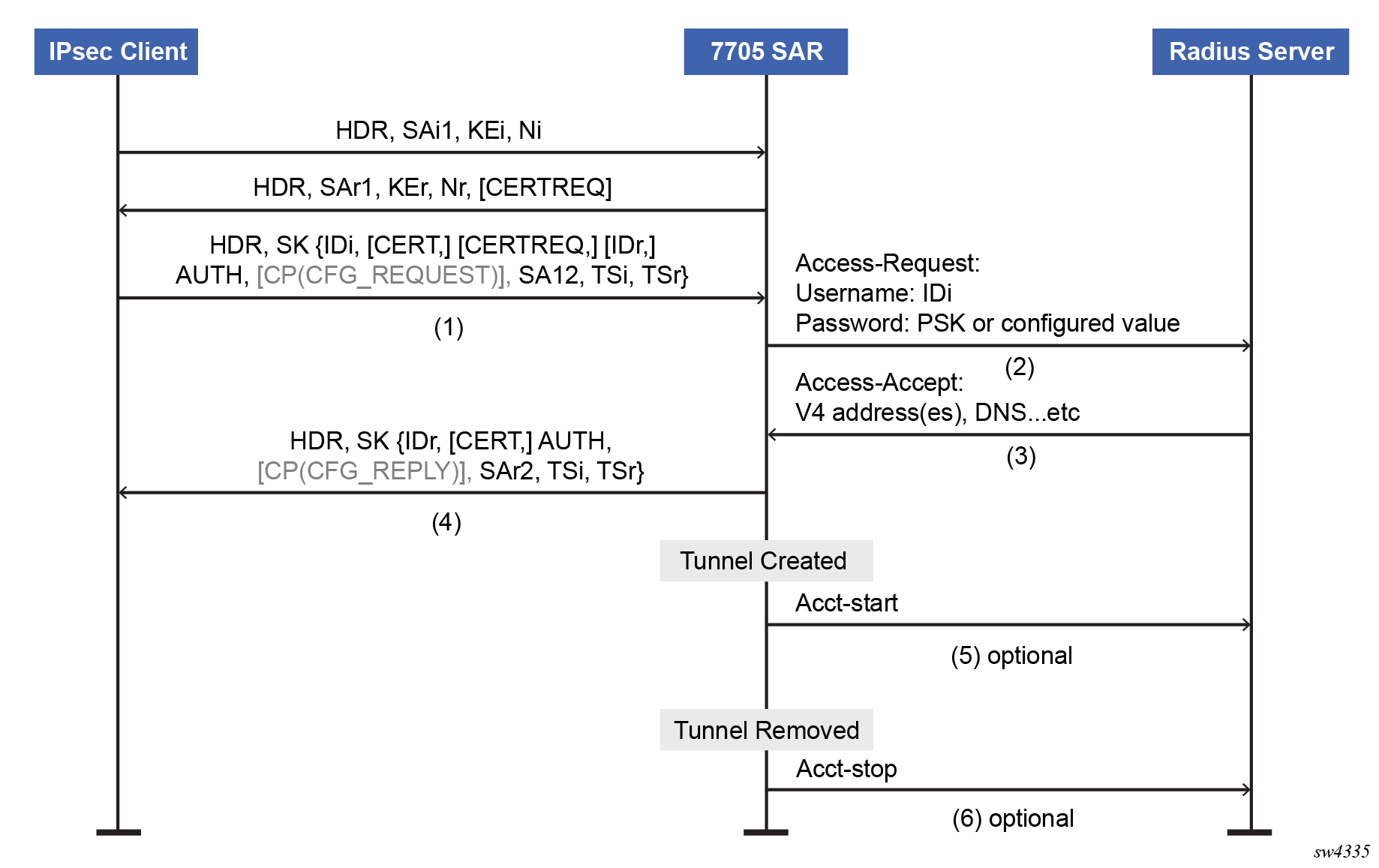
The Access-Request includes the following attributes:
-
Username is IDi.
-
User-Password is one of following value’s hash according to section 5.2 of RFC 2865, Remote Authentication Dial In User Service (RADIUS):
-
client’s PSK if psk-radius command option is configured
-
otherwise, a key configured using the password command in the RADIUS authentication policy; if a password is not configured and the system does not include the User-Password attribute in access-request.
-
-
Acct-Session-Id represents the IPsec tunnel session.
The format is: local_gw_ip-remote_ip:remote_port-time_stamp.
For example: 172.16.100.1-192.168.5.100:500-1365016423.
-
Use the following command to configure other RADIUS attributes.
- MD-CLI
configure ipsec radius authentication-policy include-radius-attribute - classic
CLI
configure ipsec radius-authentication-policy include-radius-attribute
This command configures the following command options.
-
Called-Station-Id (local tunnel address)
-
Calling-station-Id (remote tunnel address:port number)
-
Nas-Identifier (the system name)
-
Nas-Ip-Address (the system IP)
-
Nas-port-id (the public tunnel SAP ID)
- MD-CLI
If RADIUS authentication is successful, then the RADIUS server sends an access-accept message back; otherwise, an access-reject message is sent back.
The following are supported attributes in access-accept:
-
Alc-IPsec-Serv-Id
-
Alc-IPsec-Interface
-
Framed-IP-Address
-
Framed-IP-Netmask
-
Alc-Primary-Dns
-
Alc-Secondary-Dns
-
Alc-IPsec-Tunnel-Template-Id
-
Alc-IPsec-SA-Lifetime
-
Alc-IPsec-SA-PFS-Group
-
Alc-IPsec-SA-Encr-Algorithm
-
Alc-IPsec-SA-Auth-Algorithm
-
Alc-IPsec-SA-Replay-Window
After the tunnel is successfully created, the system could optionally (depending on the configuration of the RADIUS accounting policy configured in the IPsec gateway), send an accounting-start packet to the RADIUS server, and also send an accounting-stop when the tunnel is removed. The user can use the following command to enable this behavior.
- MD-CLI
configure ipsec radius accounting-policy update-interval - classic
CLI
configure ipsec radius-accounting-policy update-interval
The following are some attributes included in the acct-start/stop and interim-update:
-
Acct-status-type
-
Acct-session-id (the same as in the access-request)
-
Username
Use the following command to configure which RADIUS attributes are included.
- MD-CLI
configure ipsec radius accounting-policy include-radius-attribute - classic
CLI
configure ipsec radius-accounting-policy include-radius-attribute
This command allows the following command options.
-
Frame-ip-address: the assigned internal address
-
Calling-station-id
-
Called-station-id
-
Nas-Port-Id
-
Nas-Ip-Addr
-
Nas-Identifier
-
Acct-Session-Time (tunnel session time, only in acct-stop packet)
The system also supports RADIUS disconnect messages to remove an established tunnel, If the following command is enabled in the RADIUS server configuration, then the system accepts the disconnect-request message (RFC 5176, Dynamic Authorization Extensions to Remote Authentication Dial In User Service (RADIUS)), and tear down the specified remote-access tunnel.
- MD-CLI
configure router radius server accept-coa - classic
CLI
configure router radius-server server accept-coa
For security reasons, the system only accepts a disconnect-request when accept-coa is configured and the disconnect-request comes from the corresponding server.
The target tunnel is identified by one of following methods:
-
Acct-Session-Id
-
Nas-Port-Id + Framed-Ip-Addr(Framed-Ipv6-Prefix) + Alc-IPsec-Serv-Id
-
User-Name
By default, the system only returns what the client has requested in the CFG_REQUEST payload. However, this behavior can be overridden using the following command.
configure ipsec ike-policy relay-unsolicited-cfg-attributeWith this configuration, the configured attributes returned from the source (such as the RADIUS server) are returned to the client regardless if the client has requested it in the CFG_REQUEST payload.
IKEv2 remote-access tunnel – EAP authentication
The SR OS supports EAP authentication for a IKEv2 remote-access tunnel, in which case, the system acts as an authenticator between an IPsec client and a RADIUS server. It transparently forwards EAP messages between the IKEv2 session and RADIUS session. Thus, the actual EAP authentication occurs between the client and the RADIUS server.
Typical call flow of EAP authentication shows a typical call flow of EAP authentication.
Use the following command option to enable EAP authentication.
- MD-CLI
configure ipsec ike-policy ike-version-2 auth-method eap - classic
CLI
configure ipsec ike-policy auth-method eap
When enabled, after the received IKE_AUTH request from the client, the system sends an EAP-Response/ID with IDi as the value in the access-request to AAA. AAA returns a method request and the system starts passing through between the client and AAA (as shown in Typical call flow of EAP authentication).
The generation of the AUTH payload in the IKE_AUTH response sent by the SR OS (message 4 in flow shown above) is dependent on the following command.
- MD-CLI
configure ipsec ike-policy ike-version-2 own-auth-method - classic
CLI
configure ipsec ike-policy own-auth-method
This command allows the following command options.
- psk
- The AUTH payload is present and generated by using PSK.
- cert
- The AUTH payload is present and generated by the configured public and private key pairs as it does in certificate authentication. Any needed certificates are also sent.
- eap-only
- Neither AUTH nor CERT payload is present.
The RADIUS attributes in authentication and accounting packets are similar to psk-radius and cert-radius with the following differences:
-
RADIUS attributes support EAP-Message/Message-Authenticator/State attributes.
-
RADIUS attributes support Access-Challenge packet.
-
RADIUS attributes support MS-MPPE-Send-Key/ MS-MPPE-Recv-Key in access-accept. These two attributes are required for all EAP methods that generate MSK.
The system provides a method to support EAP and other authentication methods on the same IPsec gateway policy. Use one of the following command options to enable the correct authentication method.
- MD-CLI
configure ipsec ike-policy ike-version-2 auth-method auto-eap configure ipsec ike-policy ike-version-2 auth-method auto-eap-radius - classic
CLI
configure ipsec ike-policy auth-method auto-eap
configure ipsec ike-policy auth-method auto-eap-radius
With auto-eap:
-
If there is no AUTH payload in IKE_AUTH request, the system uses EAP to authenticate the client and also uses following command to generate the AUTH payload.
- MD-CLI
configure ipsec ike-policy ike-version-2 own-auth-method - classic
CLI
configure ipsec ike-policy own-auth-method
- MD-CLI
-
If there is an AUTH payload in the IKE_AUTH request, the authorization method is determined by the following command.
- MD-CLI
configure ipsec ike-policy ike-version-2 auto-eap-method - classic
CLI
configure ipsec ike-policy auto-eap-method
-
If the auto-eap-method is psk, the system proceeds as auth-method: psk
-
If the auto-eap-method is cert, the system proceeds as auth-method: cert
-
If the auto-eap-method is psk-or-cert:
-
If the Auth Method field of the AUTH payload is PSK, the system proceeds as auth-method: psk
-
If the Auth Method field of the AUTH payload is RSA or DSS, the system proceeds as auth-method: cert-auth
-
- MD-CLI
With auto-eap-radius:
-
If there is no AUTH payload in an IKE_AUTH request, the system uses EAP to authenticate the client and also uses the following command to generate the AUTH payload.
- MD-CLI
configure ipsec ike-policy ike-version-2 own-auth-method - classic
CLI
configure ipsec ike-policy own-auth-method
- MD-CLI
-
If there is an AUTH payload in the IKE_AUTH request, the system uses the following command to generate the AUTH payload.
- MD-CLI
configure ipsec ike-policy ike-version-2 auto-eap-own-method - classic
CLI
configure ipsec ike-policy auto-eap-own-method
-
If the auto-eap-own-method is psk, the system proceeds as auth-method: psk-radius
-
If the auto-eap-own-method is cert, the system proceeds as auth-method: cert-radius
-
If auto-eap-own-method is psk-or-cert:
-
If the Auth Method field of the AUTH payload is PSK, the system proceeds as auth-method:psk-radius
-
If the Auth Method field of the AUTH payload is RSA or DSS, the system proceeds as auth-method:cert-radius
-
- MD-CLI
IKEv2 remote-access tunnel – authentication without RADIUS
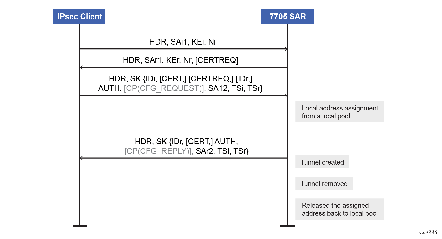
To achieve authentication without RADIUS, the authentication method needs to be configured as psk or cert-auth and a local address assignment must be configured under the IPsec gateway.
Typical call flow of certificate or PSK authentication without RADIUS shows a typical call flow of certificate or PSK authentication without RADIUS.
Typical call flow for EAP authentication shows a typical call flow for EAP authentication.
In this configuration, the RADIUS authentication and accounting policies in the IPsec gateway context are ignored.
RADIUS disconnect messages are supported in this case. Only the following tunnel identification methods are supported:
Nas-Port-Id + Framed-Ip-Addr(Framed-Ipv6-Prefix) + Alc-IPsec-Serv-Id
User-Name
IKEv2 remote-access tunnel – address assignment
The SR OS supports the following methods of address assignment for IKEv2 remote-access tunnels:
RADIUS
local address assignment (LAA)
DHCPv4/v6
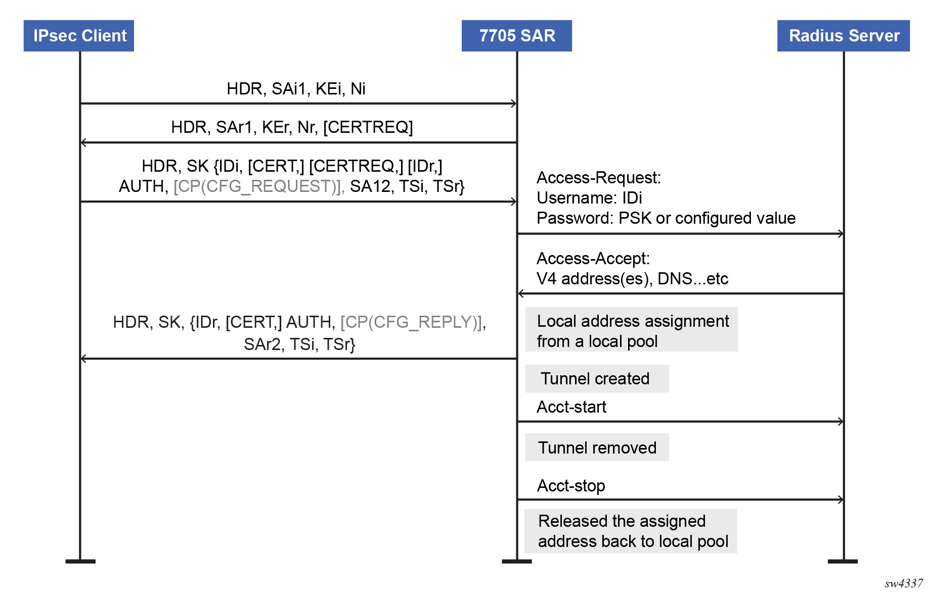
For RADIUS-based address assignment, the address information is returned in an access-accept packet. This implies that RADIUS-based address assignment requires using an authentication option with RADIUS, such as psk-radius, cert-radius, or eap.
For LAA, the system gets an address from a pool defined in a local DHCPv4/v6 server. When a tunnel is removed, the assigned address is released back to the pool. If the local DHCPv4/v6 server is shut down, all existing tunnels that have an address from the server are removed. If LAA is shut down, the current established tunnel that used LAA stays up.
For DHCP-based address assignment, the system acts as a DHCP client on behalf of the IPsec client and requests an address from an external DHCP server via the standard DHCP exchange. In this case, the system also acts as a DHCP relay agent, which relays all DHCP packets between the DHCP server and the local DHCP client. DHCP renew and rebind are also supported.
DHCPv4 address assignment
The client’s hardware address field (chaddr) in the DHCPv4 header is generated by the SR OS:
The first 2 bytes of the MAC address are 02:03.
The remaining 4 bytes are the hash result of IKEv2 IDi.
The following options are included in the DHCPv4 packets sent by the SR OS:
Option 82 circuit-id (private-SAP-id | private-interface-name; for example, tunnel-1.private:100 | priv-int)
Option 82 remote-id (IKEv2 IDi in text format)
Option 61 client-id is 1 byte that represents the IKEv2 IDi type plus the IKEv2 IDi in text format. The value of the first byte is as follows:
ID_IPV4_ADDR = 1
ID_DER_ASN1_DN = 2
ID_FQDN = 3
ID_RFC822_ADDR = 4
ID_IPV6_ADDR = 5
DHCPv6 address assignment
Because the system performs a DHCP relay function, all DHCPv6 packets sent or received are encapsulated in DHCPv6 relay-forward and relay-reply messages.
The following items are values of key fields and options in DHCPv6 packets sent by the system:
Hop-count (0)
Link address (configurable via the CLI)
Peer-address (auto-generated based on the IKEv2 IDi)
Option 1 Client Identifier
DUID type (2)
Enterprise ID (6527)
Value is 1 byte that represents the IKEv2 IDi type plus the IKEv2 IDi in text format. The value of the first byte is the same as that of the first byte in Option 61 for DHCPv4.
Option 16 Vendor Class
Enterprise ID (6527)
Value (string ‟SROS IPsec”)
Option 18 Interface ID (private-SAP-id | private-interface-name; for example, tunnel-1.private:100 | priv-int)
Option 37 Remote Identifier
Enterprise ID (6527)
Value (IKEv2 IDi in text format)
DHCPv4/v6 usage notes
-
Using a local DHCP server on the same chassis for DHCP-based address assignment is not supported. The DHCP server must be external.
-
IPsec DHCP relay uses only the following command gi-address configuration found under the IPsec gateway and does not take into account the gateway IP address with a source IP address configuration on any other interfaces.
- MD-CLI
configure service ies interface sap ipsec-gateway dhcp-address-assignment dhcpv4 gi-address configure service vprn interface sap ipsec-gateway dhcp-address-assignment dhcpv4 gi-address - classic
CLI
configure service ies interface sap ipsec-gw dhcp gi-address
configure service vprn interface sap ipsec-gw dhcp gi-address
- MD-CLI
-
The following command must be enabled on an interface that has a gateway IP address as the interface address for the interface to use a DHCPv4 address assignment. The system ignores other DHCP or DHCPv6 configurations on the interface, with the exception of the relay-proxy configuration.
- MD-CLI
configure service ies interface ipv4 dhcp relay-proxy configure service vprn interface ipv4 dhcp relay-proxy - classic
CLI
configure service ies interface dhcp relay-proxy
configure service vprn interface dhcp relay-proxy
-
If the DHCP server resides in a private service, and the gateway IP address is an address configured on the corresponding tunnel interface, relay-proxy must be enabled on the corresponding private interface.
-
If the DHCP server resides in a routing instance that is different from the private service, then there must be an interface (such as a loopback interface) in the routing instance that has the gateway IP address as the interface address, and gateway IP address must be routable for the DHCP server. Also, the relay proxy must be enabled on the interface in the routing instance.
- MD-CLI
The biggest difference between the LAA and DHCP-based methods is that LAA uses a local API to get an address from a local pool. There is no DHCP packet exchange for LAA, while a DHCP-based method uses standard DHCP packet exchange to request a packet from an external DHCP server.
Because there are three methods for address assignment, the following is the priority order (descending) of sources to choose if more than one source is configured:
LAA
DHCP
RADIUS
There is no fallback between the different sources.
LAA/DHCP can work with an authentication method that does not involve RADIUS, as well as with an authentication method that involves RADIUS. When using LAA/DHCP with an authentication method that involves RADIUS, the following applies:
LAA/DHCP only happens after RADIUS is successfully authenticated.
The address information returned by the RADIUS server is ignored (even if LAA/DHCP is configured but is shut down).
Non-address-related attributes in access-accept messages such as Alc-IPsec-Serv-Id and Alc-IPsec-Tunnel-Template-Id are still accepted.
RADIUS accounting is supported in this case, but the Framed-IP-Addr/Framed-IPv6-Prefix reported in the acct-request packet is the LAA/DHCP assigned address, not the address returned by the RADIUS server.
RADIUS disconnect messages are supported.
IPv6 IPsec support
The SR OS provides the following IPv6 support to IPsec functions:
IPv6 packets as the ESP tunnel payload
IPv6 as the ESP tunnel encapsulation
IPv6 as payload
IPv6 as payload allows IPv6 packets to be forwarded within an IPsec tunnel. Current support includes the following:
Tunnel type support includes:
static LAN-to-LAN tunnel
dynamic LAN-to-LAN tunnel
remote-access tunnel (only IKEv2 is supported)
The prefix length of the IPv6 address on a private interface must be /96 or longer.
IPv6 as payload: static LAN-to-LAN tunnel
There are three methods to forward IPv6 traffic into static tunnels on the private side:
-
The destination address is a configured destination IP under the tunnel context.
-
The destination IP can be either an IPv6 address or an IPv4 address.
-
In the case of IPv6, it must be either an IPv6 global unicast address or an IPv6 link-local address.
-
In the case of IPv4, it can be used to forward IPv4 traffic into the tunnel.
-
In case of unicast address, dest-ip must be within the prefix configured on the private interface.
-
Up to 16 destination IP addresses can be configured per IPsec tunnel.
-
-
A v6 route with a configured destination IP as the next-hop, this route can be learned from either a static or dynamic from a routing protocol such as BGP.
-
An IPv6 static route with an ipsec-tunnel used as the next-hop.
A security policy supports either an IPv4 entry or an IPv6 entry or both for dual-stack.
IPv6 as payload: dynamic LAN-to-LAN tunnel
With dynamic LAN-to-LAN tunnels, the system automatically creates a v6 reverse route in the private VPRN based on the received TSi payload with the tunnel as the next hop.
IPv6 as payload: remote-access tunnel
The system supports the following IKEv2 IPv6 configuration attributes:
INTERNAL_IP6_ADDRESS
INTERNAL_IP6_DNS
The system supports only one internal IPv6 address per tunnel. The following IPv6-related RADIUS attributes are also supported in access-accept:
Framed-IPv6-Prefix is translated into INTERNAL_IP6_ADDRESS in the configuration payload, which includes two parts. A 16-byte v6 prefix and a one-byte prefix length.
Alc-Ipv6-Primary-Dns
Alc-Ipv6-Secondary-Dns
If an internal v6 address has been assigned to the remote-access client, then the Framed-IPv6-Prefix is also included in RADIUS accounting-request packet. The assigned internal v6 address must be within the prefix configured on the corresponding private interface.
If the client request both v4 and v6 address and address source (such as RADIUS or LAA) assign both v4 and v6 address, then both v4 and v6 addresses are assigned to the client via the configuration payload.
IPv6 as encapsulation
IPv6 as encapsulation allows IPv4 or IPv6 packets to be forwarded within an IPv6 ESP tunnel, also the IKE protocol can run over IPv6. Current support only includes tunnel type support:
-
static LAN-to-LAN tunnel
-
dynamic LAN-to-LAN tunnel
-
remote-access tunnel (For IKEv1, only v4 over v6 is supported)
For an ipsec-gw or ipsec-tunnel, only one local gateway address is supported, which could be either an IPv4 or IPv6 address. The SR OS also provides fragmentation and reassembly support for IPv6 ESP/IKE packets.
Secured interface
A secured interface secures traffic forwarded through a specified IP interface, through one or multiple Secure Interface Tunnels (SI Tunnels) configured under the interface. SI tunnel is conceptually the same as traditional static IPsec tunnels. Some differences are:
-
SI tunnels are configured under an IP interface, while static IPsec tunnels are configured under the private tunnel SAP of a tunnel interface.
-
With an SI tunnel, the following objects are created automatically with an SI tunnel configuration. There is no need for a separate configuration tunnel configuration:
-
public tunnel SAP
-
public interface
-
private tunnel SAP
-
private tunnel interface
-
-
The public service of SI tunnel is the same service of secured interface, which could be either base router, an IES or an VPRN service.
-
The local tunnel address of the SI tunnel must be one of interface addresses of the secure interface. If the secure interface is unnumbered, then it must be one of the interface address of the interface specified by the unnumbered configuration.
-
Private service is the same as the public service. The user could also specify a different service.
-
On the public side:
-
With a secured interface, by default, all traffic ingress the interface are subject to IPsec processing. If the received traffic is not IPsec traffic (such as ESP and IKE), it is dropped. Use the following commands to change this behavior.
configure filter ip-exception
configure filter ipv6-exception
All ingress traffic matching the configured exception filter bypasses IPsec processing and is forwarded through normal routing methods.
-
The system forwards all SI tunnel traffic (after encryption and encapsulation) out through the corresponding secured interface.
-
SSH traffic toward the local system and MPLS/SDP always bypasses IPsec processing.
-
-
On the private side:
-
Like a static IPsec tunnel, traffic is routed into the SI tunnel through a static route or BGP route.
-
When an SI tunnel is operationally down, routes using the next-hop address as the tunnel are unresolved and withdrawn from the route table.
-
-
show, debug, tool, clear, and admin commands that apply to static IPsec tunnels also apply to SI tunnels.
-
The following features are not supported with SI tunnels on 7705 SAR Gen 2 (with cellular exit port):
-
destination IP
-
MC-IPsec
-
IPv4 over IPv6
-
IPv6 over IPv6
-
MLDv2 over SI tunnel
-
-
The following features are not supported with SI tunnels on 7705 SAR Gen 2:
-
destination IP
-
MC-IPsec
-
MLDv2 over SI tunnel
-
Configuring IPsec with CLI
Provisioning a tunnel ISA
The following example displays a card and ISA configuration.
MD-CLI
[ex:/configure]
A:admin@node-2# info
card 1 {
        card-type iom4-e
        mda 1 {
            mda-type me40-1gb-csfp
        }
        mda 2 {
            mda-type isa2-tunnel
        }
classic CLI
A:node-2>config# info
----------------------------------------------
...
    card 1
        card-type iom4-e
        mda 1
            mda-type me40-1gb-csfp
            no shutdown
        exit
        mda 2
            mda-type isa2-tunnel
            no shutdown
        exit
        no shutdown
...
----------------------------------------------
Configuring a tunnel group
The following example displays a tunnel group configuration in the ISA context. The multi-active command specifies that there could be multiple active ISAs in the tunnel group.
MD-CLI
[ex:/configure]
A:admin@node-2# info
isa {
        tunnel-group 1 {
            admin-state enable
            isa-scale-mode tunnel-limit-2k
            multi-active {
                isa 1/2 { }
            }
        }
    }
classic CLI
A:node-2>config# info
----------------------------------------------
...
    isa
        tunnel-group 1 isa-scale-mode tunnel-limit-2k create
            multi-active
            mda 1/2
            no shutdown
        exit
    exit
...
----------------------------------------------
Configuring router interfaces for IPsec
The following example displays an interface named ‟internet” that is configured using the network port (1/1/1), which provides network connection on the public side.
MD-CLI
[ex:/configure router "Base"]
A:admin@node-2# info
    autonomous-system 123
    interface "internet" {
        port 1/1/1
        ipv4 {
            primary {
                address 10.10.7.118
                prefix-length 24
            }
        }
    }
    interface "system" {
        ipv4 {
            primary {
                address 10.20.1.118
                prefix-length 32
            }
        }
    }
classic CLI
A:node-2>config# info
----------------------------------------------
...
    router Base
        interface "internet"
            address 10.10.7.118/24
            port 1/1/1
            no shutdown
        exit
        interface "system"
            address 10.20.1.118/32
            no shutdown
        exit
        autonomous-system 123

...
----------------------------------------------
Configuring IPsec command options
The following example displays an IPsec configuration.
MD-CLI
[ex:/configure ipsec]
A:admin@node-2# info
    ike-policy 100 {
        ike-transform [100]
        ike-version-2 {
            auth-method eap
        }
    }
    ike-transform 100 {
        dh-group group-14
        ike-auth-algorithm sha-256
        isakmp-lifetime 90000
    }
classic CLI
A:node-2>config>ipsec# info
----------------------------------------------
        ike-transform 100 create
            dh-group 14
            ike-auth-algorithm sha256
            isakmp-lifetime 90000
        exit
        ike-policy 100 create
            ike-version 2
            auth-method eap
            ike-transform 100
        exit
----------------------------------------------
Configuring IPsec in services
The following example displays an IES and VPRN service with IPsec command options configured.
MD-CLI
[ex:/configure service]
A:admin@node-2# info
    ies "100" {
        admin-state enable
        customer "1"
        interface "ipsec-public" {
            sap tunnel-1.public:1 {
            }
            ipv4 {
                primary {
                    address 10.10.10.1
                    prefix-length 24
                }
            }
        }
    }

    vprn "200" {
    admin-state enable
    customer "1"
    ipsec {
        security-policy 1 {
            entry 1 {
                local-ip {
                    address 172.16.118.0/24
                }
                remote-ip {
                    address 172.16.91.0/24
                }
            }
        }
    }
    bgp-ipvpn {
        mpls {
            admin-state enable
            route-distinguisher "1:1"
        }
    }
    interface "corporate-network" {
        ipv4 {
            primary {
                address 172.16.118.118
                prefix-length 24
            }
        }
        sap 1/1/2 {
        }
    }
    interface "ipsec-private" {
        tunnel true
        sap tunnel-1.private:1 {
            ipsec-tunnel "remote-office" {
                key-exchange {
                    dynamic {
                        ike-policy 1
                        ipsec-transform [1]
                        pre-shared-key "0PuXIi3wAoMOkSffbuDDViSy4jnc4N2vRrT1Qw== hash2"
                    }
                }
                tunnel-endpoint {
                    local-gateway-address 10.10.10.118
                    remote-ip-address 10.10.7.91
                    delivery-service "delivery"
                }
                security-policy {
                    id 1
                }
            }
        }
    static-routes {
        route 172.16.91.0/24 route-type unicast {
            ipsec-tunnel "t1" {
                admin-state enable
            }

    }
classic CLI
A:node-2>config# info
----------------------------------------------
...
    service
        ies 100 name "100" customer 1 create
            interface "ipsec-public" create
                address 10.10.10.1/24
                tos-marking-state untrusted
                sap tunnel-1.public:1 create
                exit
            exit
            no shutdown
        exit
  vprn 200 customer 1 create
            ipsec
                security-policy 1 create
                    entry 1 create
                        local-ip 172.16.118.0/24
                        remote-ip 172.16.91.0/24
                    exit
                exit
            exit
            route-distinguisher 1:1
            interface "ipsec-private" tunnel create
                sap tunnel-1.private:1 create
                    ipsec-tunnel "remote-office" create
                        security-policy 1
                        local-gateway-address 10.10.10.118 peer 10.10.7.91 delivery-service-name delivery
                        dynamic-keying
                            ike-policy 1
                            pre-shared-key "humptydumpty"
                            transform 1
                        exit
                        no shutdown
                    exit
                exit
            exit
            interface "corporate-network" create
                address 172.16.118.118/24
                sap 1/1/2 create
                exit
            exit
            static-route-entry 172.16.91.0/24
                ipsec-tunnel "t1"
                    no shutdown
                exit
            exit
            no shutdown
        exit
    exit
...
----------------------------------------------
Configuring X.509v3 certificate command options
The following are steps to configure certificate enrollment:
-
Generate a key.
- MD-CLI
admin system security pki generate-keypair cf3:/key_plain_rsa2048 admin system security pki generate-keypair rsa-key-size 2048 - classic
CLI
admin certificate gen-keypair cf3:/key_plain_rsa2048 size 2048 type rsa
- MD-CLI
-
Generate a certificate request.
- MD-CLI
admin system security pki generate-csr key-url cf3:/key_plain_rsa2048 output-url cf3:/7750-req.cs subject-dn "C=US,ST=CA,CN=7750" - classic
CLI
admin certificate gen-local-cert-req keypair cf3:/key_plain_rsa2048 subject-
dn "C=US,ST=CA,CN=7750" file 7750_req.cs
- MD-CLI
-
Send the certificate request to CA-1 to sign and get the signed certificate.
-
Import the key.
- MD-CLI
admin system security pki import type key input-url cf3:/key_plain_rs2048 output-file key1_rsa2048 format der - classic
CLI
admin certificate import type key input cf3:/key_plain_rsa2048 output key1_rsa2048 format der
- MD-CLI
-
Import the signed certificate.
- MD-CLI
admin system security pki import type cert input-url cf3:/7750_cert.pem output-file 7750cert format pem - classic
CLI
admin certificate import type cert input cf3:/7750_cert.pem output 7750cert format pem
- MD-CLI
The following are steps to configure CA certificate/CRL import.
-
Import the CA certificate.
- MD-CLI
admin system security pki import type certificate input-url cf3:/CA_1_cert.pem output-file ca_cert format pem - classic
CLI
admin certificate import type cert input cf3:/CA_1_cert.pem output ca_cert format pem
- MD-CLI
-
Import the CA’s CRL.
- MD-CLI
admin system security pki import type certificate input-url cf3:/CA_1_crl.pem output-file ca_crl format pem - classic
CLI
admin certificate import type crl input cf3:/CA_1_crl.pem output ca_crl format pem
- MD-CLI
The following example displays a certificate authentication for IKEv2 static LAN-to-LAN tunnel configuration.
MD-CLI
[ex:/configure system security pki]
A:admin@node-2# info
    ca-profile "NOKIA-root" {
        admin-state enable
        cert-file "NOKIA_root.cert"
        crl-file "NOKIA_root.crl"
    }

[ex:/configure ipsec]
A:admin@node-2# info
    cert-profile "segw" {
        admin-state enable
        entry 1 {
            cert "segw.cert"
            key "segw.key"
        }
    }
    ike-policy 1 {
        ike-transform [1]
        ike-version-2 {
            auth-method cert
        }
    }
    ike-transform 1 {
    }
    ipsec-transform 1 {
    }
    trust-anchor-profile "nokia" {
        trust-anchor "NOKIA-root" { }
    }

[ex:/configure service vprn "200" interface "ipsec-private" sap tunnel-1.private:1]
A:admin@node-2# info
    ipsec-tunnel "t50" {
        admin-state enable
        key-exchange {
            dynamic {
                ike-policy 1
                ipsec-transform [1]
                cert {
                    cert-profile "segw"
                    trust-anchor-profile "nokia"
                }
            }
        }
        tunnel-endpoint {
            local-gateway-address 192.168.55.30
            remote-ip-address 192.168.33.100
            delivery-service "delivery"
        }
        security-policy {
            id 1
        }
    }
classic CLI
A:node-2>config>system>security>pki# info
----------------------------------------------
                ca-profile "NOKIA-root" create
                    cert-file "NOKIA_root.cert"
                    crl-file "NOKIA_root.crl"
                    no shutdown
                exit
----------------------------------------------

A:node-2>config>ipsec# info
----------------------------------------------
        ike-policy 1 create
            ike-version 2
            auth-method cert-auth
            ike-transform 1
        exit
        ipsec-transform 1 create
        exit
        ike-transform 1 create
        exit
       cert-profile "segw" create
            entry 1 create
                cert segw.cert
                key segw.key
            exit
            no shutdown
        exit
        trust-anchor-profile "nokia" create
            trust-anchor "nokia-root"
        exit
----------------------------------------------

A:node-2>config>service>vprn>if>sap
----------------------------------------------
                    ipsec-tunnel "t50" create
                        security-policy 1
                        local-gateway-address 192.168.55.30 peer 192.168.33.100 delivery-service delivery
                        dynamic-keying
                            ike-policy 1
                            transform 1
                            cert
                                trust-anchor-profile "nokia"
                                cert-profile "segw"
                            exit
                        exit
                        no shutdown
                    exit
Configuring and using CMPv2
CMPv2 server information is configured using the commands in the following context.
configure system security pki ca-profile cmpv2The following command options are configured in this context:
-
url
This command option specifies the HTTP URL of the CMPv2 server. The service specifies the routing instance that the system used to access the CMPv2 server (if omitted, then system uses the base routing instance).
-
service name or service ID
This command option is only needed for in-band connections to the server via VPRN services. IES services are not referenced by the service ID as they use the base routing instance.
-
response-signing-cert
This command option specifies an imported certificate used to verify the CMP response message if it is protected by signature. If this command is not configured, the CA certificate is used.
-
key-list
This command option specifies a list of pre-shared keys used for CMPv2 initial registration message protection.
If there is no key list defined in the CMPv2 configuration, the system defaults to the CMPv2 transaction input for the command line for authenticating a message without a sender ID. Also, if there is no sender ID in the response message, and there is a key list defined, the system chooses the lexicographical first entry only, and if that fails, it outputs a fail result for the transaction.
- MD-CLI
admin system security pki cmpv2 - classic
CLI
admin certificate cmpv2
The system also supports optional commands (such as, always-set-sender-ir) to support inter-op with CMPv2 servers.
The following example displays CMPv2 configuration.
MD-CLI
[ex:/configure system security pki ca-profile "profile" cmpv2]
A:admin@node-2# info
    response-signing-cert "filename"
    url {
        url-string "http://cmp.example.com/request"
        service-name "foo"
    }
    key-list {
        key "1" {
            password "RGwT0+xs+Zb9708mSFdzMCxTCu8ykxuSpA2mpHzFwzU= hash2"
        }
    }
classic CLI
A:node-2>config>system>security>pki>ca-profile>cmpv2$ info
----------------------------------------------
                        url "http://cmp.example.com/request" service-name "foo"
                        key-list
                                key "RGwT0+xs+Zb9708mSFdzMCxTCu8ykxuSpA2mpHzFwzU=" hash2 reference "1"
                        exit
                        response-signing-cert "filename"
----------------------------------------------
Configuring OCSP
OCSP server information is configured using the following command.
configure system security pki ca-profile ocspThe responder-url command option specifies the HTTP URL of the OCSP responder. The service ID or service name command option specifies the routing instance that system used to access the OCSP responder.
For an IPsec tunnel or IPsec gateway, the user can configure a primary method, a secondary method and a default result using the following commands:
- MD-CLI
configure ipsec ipsec-transport-mode-profile key-exchange dynamic cert status-verify configure router interface ipsec ipsec-tunnel key-exchange dynamic cert status-verify configure service ies interface ipsec ipsec-tunnel key-exchange dynamic cert status-verify configure service vprn interface ipsec ipsec-tunnel key-exchange dynamic cert status-verify configure service vprn interface sap ipsec-tunnel key-exchange dynamic cert status-verify - classic
CLI
configure service vprn interface sap ipsec-gw cert status-verify
configure service ies interface sap ipsec-gw cert status-verify
configure service vprn interface ipsec ipsec-tunnel dynamic-keying cert status-verify
configure service vprn interface sap ipsec-tunnel dynamic-keying cert status-verify
configure service ies interface ipsec ipsec-tunnel dynamic-keying cert status-verify
The following example, shows OCSP configured as the primary method and CRL as the secondary method.
MD-CLI
[ex:/configure service ies "2" interface "ipsec-pub" sap tunnel-1.public:100 ipsec-gateway "foo"]
A:admin@node-2# info
    cert {
        status-verify {
            primary ocsp
            secondary crl
        }
    }
classic CLI
A:node-2>config>service>ies>if>sap>ipsec-gw# info
----------------------------------------------
                        shutdown
                        cert
                            status-verify
                                primary ocsp secondary crl
                            exit
                        exit
----------------------------------------------
Configuring IKEv2 remote-access tunnel
The following are configuration tasks for an IKEv2 remote-access tunnel:
-
Create an IKE policy with one of the authentication methods that enabled the remote-access tunnel.
-
Configure a tunnel template or IPsec transform. This is the same as configuring a dynamic LAN-to-LAN tunnel.
-
Create a RADIUS authentication policy and optionally, a RADIUS accounting policy (a RADIUS server policy and a RADIUS server must be preconfigured).
-
Configure a private VPRN service and private tunnel interface with an address on the interface. The internal address assigned to the client must come from the subnet on the private interface.
-
Configure a public IES or VPRN service and an IPsec gateway under the public tunnel SAP.
-
Configure the RADIUS authentication policy and RADIUS accounting policy (optional) under the IPsec gateway.
-
Configure a certificate if any certificate-related authentication method is used.
The following example shows an IKEv2 configuration using cert-radius.
MD-CLI
[ex:/configure system security pki]
A:admin@node-2# info
    ca-profile "NOKIA-ROOT" {
        admin-state enable
        cert-file "NOKIA-ROOT.cert"
        crl-file "NOKIA-ROOT.crl"
    }

[ex:/configure aaa]
A:admin@node-2# info
    radius {
        server-policy "femto-aaa" {
            servers {
                router-instance "management"
                server 1 {
                    server-name "svr-1"
                }
            }
        }
    }

[ex:/configure router "Base"]
A:admin@node-2# info
    radius {
        server "svr-1" {
            address 10.10.1.2
            secret "LCa0a2j/xo/5m0U8HTBBNJYdag== hash2"
        }
    }

[ex:/configure ipsec]
A:admin@node-2# info
    cert-profile "c1" {
        admin-state enable
        entry 1 {
            cert "SeGW2.cert"
            key "SeGW2.key"
        }
    }
    ike-policy 1 {
        ike-transform [1]
        ike-version-2 {
            auth-method cert-radius
        }
    }
    ike-transform 1 {
    }
    ipsec-transform 1 {
    }
    tunnel-template 1 {
        ipsec-transform [1]
    }
    trust-anchor-profile "tap-1" {
        trust-anchor "NOKIA-ROOT" { }
    }
    radius {
        accounting-policy "femto-acct" {
            radius-server-policy "femto-aaa"
            include-radius-attribute {
                calling-station-id true
                framed-ip-addr true
            }
        }
        authentication-policy "femto-auth" {
            radius-server-policy "femto-aaa"
            password "CQsjXp648Zfy3ZJ5NyIsV7gcSkI= hash2"
            include-radius-attribute {
                called-station-id true
                calling-station-id true
            }
        }
    }


[ex:/configure service ies "2"]
A:admin@node-2# info
    admin-state enable
    customer "1"
    interface "pub" {
        sap tunnel-1.public:100 {
            ipsec-gateway "rw" {
                admin-state enable
                default-tunnel-template 1
                ike-policy 1
                cert {
                    cert-profile "c1"
                    trust-anchor-profile "tap-1"
                }
                default-secure-service {
                    service-name "priv"
                    interface "priv"
                }
                radius {
                    accounting-policy "femto-acct"
                    authentication-policy "femto-auth"
                }
            }
        }
        ipv4 {
            primary {
                address 172.16.100.0
                prefix-length 31
            }
        }
    }

[ex:/configure service vprn "1"]
A:admin@node-2# info
    admin-state enable
    bgp-ipvpn {
        mpls {
            admin-state enable
            route-distinguisher "400:11"
        }
    }
    interface "l1" {
        loopback true
        ipv4 {
            primary {
                address 10.9.9.9
                prefix-length 32
            }
        }
    }
    interface "priv" {
        tunnel true
        ipv4 {
            addresses {
                address 10.20.20.1 {
                    prefix-length 24
                }
            }
        }
        sap tunnel-1.private:200 {
        }
    }
classic CLI
A:node-2>config>system>security>pki# info
----------------------------------------------
                ca-profile "NOKIA-ROOT" create
                    cert-file "NOKIA-ROOT.cert"
                    crl-file "NOKIA-ROOT.crl"
                    no shutdown
                exit
----------------------------------------------

A:node-2>config>aaa# info
----------------------------------------------
        radius-server-policy "femto-aaa" create
            servers
                router "management"
                server 1 name ‟svr-1"
            exit
        exit
----------------------------------------------

A:node-2>config>router# info
----------------------------------------------
        radius-server
            server ‟svr-
1" address 10.10.10.1 secret "KR35xB3W4aUXtL8o3WzPD." hash2 create
            exit
        exit
----------------------------------------------

A:node-2>config>ipsec# info
----------------------------------------------
        ike-policy 1 create
            ike-version 2
            auth-method cert-radius
            ike-transform 1
        exit
        ipsec-transform 1 create
        exit
        ike-transform 1 create
        exit
        tunnel-template 1 create
            transform 1
        exit
        cert-profile "c1" create
            entry 1 create
                cert SeGW2.cert
                key SeGW2.key
            exit
            no shutdown
        exit
        trust-anchor-profile "tap-1" create
            trust-anchor "NOKIA-ROOT"
        exit
radius-authentication-policy "femto-auth" create
            include-radius-attribute
                calling-station-id
                called-station-id
            exit
            password "DJzlyYKCefyhomnFcFSBuLZovSemMKde" hash2
            radius-server-policy "femto-aaa"
        exit
        radius-accounting-policy "femto-acct" create
            include-radius-attribute
                calling-station-id
                framed-ip-addr
            exit
            radius-server-policy "femto-aaa"
        exit
----------------------------------------------

A:node-2>config>service>ies# info
----------------------------------------------
            interface "pub" create
                address 172.16.100.0/31
                tos-marking-state untrusted
                sap tunnel-1.public:100 create
                    ipsec-gw "rw"
                        cert
                            trust-anchor-profile "tap-1"
                            cert-profile "c1"
                        exit
                        default-secure-service 400 interface "priv"
                        default-tunnel-template 1
                        ike-policy 1
                        local-gateway-address 172.16.100.1
                        radius-accounting-policy "femto-acct"
                        radius-authentication-policy "femto-auth"
                        no shutdown
                    exit
                exit
            exit
            no shutdown
----------------------------------------------

A:node-2>config>service>vprn# info
----------------------------------------------
            interface "priv" tunnel create
                address 10.20.20.1/24
                sap tunnel-1.private:200 create
                exit
            exit
            interface "l1" create
                address 10.9.9.9/32
                loopback
            exit
            bgp-ipvpn
                mpls
                    route-distinguisher 400:11
                    no shutdown
                exit
            exit
            no shutdown
----------------------------------------------
Configuring IKEv2 remote-access tunnel with local address assignment
The following are configuration tasks of IKEv2 remote-access tunnel:
-
Create an IKE policy with any authentication method.
-
Configure the tunnel template or IPsec transform. This is the same as configuring a dynamic LAN-to-LAN tunnel.
-
Configure a private VPRN service and a private tunnel interface with an address on the interface. The internal address assigned to the client must come from the subnet on the private interface.
-
Configure a local DHCPv4 or DHCPv6 server with address pool that from which the internal address to be assigned from.
-
Configure public IES or VPRN service and IPsec gateway under public tunnel SAP.
-
Configure the local address assignment under the IPsec gateway.
The following example shows an IKEv2 remote-access tunnel using cert-auth.
MD-CLI
[ex:/configure system security pki]
A:admin@node-2# info
      ca-profile "smallcell-root" {
        admin-state enable
        cert-file "smallcell-root-ca.cert"
        revocation-check crl-optional
    }


[ex:/configure ipsec]
A:admin@node-2# info
     cert-profile "segw-mlab" {
        admin-state enable
        entry 1 {
            cert "SeGW-MLAB.cert"
            key "SeGW-MLAB.key"
        }
    }
    ike-policy 3 {
        ike-transform [1]
        ike-version-2 {
            auth-method cert
        }
        nat-traversal {
        }
    }
    ike-transform 1 {
    }
    ipsec-transform 1 {
    }
    tunnel-template 1 {
        ipsec-transform [1]
    }
    trust-anchor-profile "sc-root" {
        trust-anchor "smallcell-root" {
        }
    }


[ex:/configure service ies "2"]
A:admin@node-2# info
    admin-state enable
    customer "1"
    interface "pub" {
        sap tunnel-1.public:100 {
            ipsec-gateway "rw" {
                admin-state enable
                default-tunnel-template 1
                ike-policy 3
                cert {
                    cert-profile "segw-mlab"
                    trust-anchor-profile "sc-root"
                    status-verify {
                        default-result good
                    }
                }
                default-secure-service {
                    service-name "priv"
                    interface "priv"
                }
                local {
                    gateway-address 172.16.100.1
                    id {
                        fqdn "segwmobilelab.nokia.com"
                    }
                    address-assignment {
                        admin-state enable
                        ipv6 {
                            router-instance "priv"
                            dhcp-server "d6"
                            pool "1"
                        }
                    }
                }
            }
        }
        ipv4 {
            primary {
                address 172.16.100.253
                prefix-length 24
            }
        }
    }


[ex:/configure service vprn "3"]
A:admin@node-2# info
    admin-state enable
    bgp-ipvpn {
        mpls {
            admin-state enable
            route-distinguisher "400:1"
        }
    }
    interface "priv" {
        admin-state enable
        tunnel true
        sap tunnel-1.private:200 {
        }
        ipv6 {
            address 2001:db8:beef::101 {
                prefix-length 96
            }
        }
    }
    dhcp-server {
        dhcpv6 "d6" {
            admin-state enable
            pool-selection {
                use-pool-from-client {
                }
            }
            pool "1" {
                options {
                    option dns-server {
                        hex-string 0x20010db8beef00000000000000000808
                    }
                }
                prefix 2001:db8:beef::/96 {
                    failover-control-type access-driven
                }
                exclude-prefix 2001:db8:beef::101/128 { }
            }
        }
    }
classic CLI
A:node-2>config>system>security>pki# info
----------------------------------------------
                ca-profile "smallcell-root" create
                    cert-file "smallcell-root-ca.cert"
                    revocation-check crl-optional
                    no shutdown
                exit
----------------------------------------------

A:node-2>config>ipsec# info
----------------------------------------------
        ike-policy 3 create
            ike-version 2
            auth-method cert-auth
            nat-traversal
            ike-transform 1
        exit
        ipsec-transform 1 create
        exit
        ike-transform 1 create
        exit
        cert-profile "segw-mlab" create
            entry 1 create
                cert SeGW-MLAB.cert
                key SeGW-MLAB.key
            exit
            no shutdown
        exit
        trust-anchor-profile "sc-root" create
            trust-anchor "smallcell-root"
        exit
        tunnel-template 1 create
            transform 1
        exit
----------------------------------------------

A:node-2>config>service>ies# info
----------------------------------------------
            interface "pub" create
                address 172.16.100.253/24
                tos-marking-state untrusted
                sap tunnel-1.public:100 create
                    ipsec-gw "rw"
                        default-secure-service 400 interface "priv"
                        default-tunnel-template 1
                        ike-policy 3
                        local-address-assignment
                            ipv6
                                address-source router 400 dhcp-server "d6" pool "1"
                            exit
                            no shutdown
                        exit
                        local-gateway-address 172.16.100.1
                        cert
                            trust-anchor-profile "sc-root"
                            cert-profile "segw-mlab"
                            status-verify
                                default-result good
                            exit
                        exit
                        local-id type fqdn value segwmobilelab.nokia.com
                        no shutdown
                    exit
                exit
            exit
            no shutdown
----------------------------------------------

A:node-2>config>service>vprn# info
----------------------------------------------
            dhcp6
                local-dhcp-server "d6" create
                    use-pool-from-client
                    pool "1" create
                        options
                            dns-server 2001:db8:::808:808
                        exit
                        exclude-prefix 2001:db8:beef::101/128
                        prefix 2001:db8::beef::/96 failover access-driven pd wan-host create
                        exit
                    exit
                    no shutdown
                exit
            exit
            bgp-ipvpn
                mpls
                    route-distinguisher 400:1
                    no shutdown
                exit
            exit
            interface "priv" tunnel create
                ipv6
                    address 2001:db8:beef::101/96
                exit
                sap tunnel-1.private:200 create
                exit
            exit
            no shutdown
Configuring secured interfaces
The following example displays a configuration for a secured interface. In this example, a SI tunnel ‟t1” is configured under interface ‟toPeer-1” in Base routing instance, along with an exception filter 100 that allows OSPF packets bypass IPsec processing.
MD-CLI
[ex:/configure filter]
A:admin@node-2# info
    ip-exception "100" {
        entry 10 {
            match {
                protocol ospf-igp
            }
        }
    }


*[ex:/configure router "Base"]
A:admin@node-2# info
    interface "toPeer-1" {
        ipsec {
            tunnel-group 1
            public-sap 300
            ip-exception "100"
            ipsec-tunnel "t1" {
                private-sap 300
                local-gateway-address-override 192.168.110.20
                remote-gateway-address 172.16.21.1
                key-exchange {
                    dynamic {
                        ike-policy 3
                        ipsec-transform [2]
                        pre-shared-key "mEg8brQLbDGkSMIqZt7TtTpKaT7xPCY= hash2"
                    }
                }
                security-policy {
                    id 1
                }
            }
        }
        ipv4 {
            primary {
                address 192.168.110.20
                prefix-length 24
            }
        }
    }
    ipsec {
        security-policy 1 {
            entry 1 {
                local-ip {
                    address 100.0.0.20/32
                }
                remote-ip {
                    address 200.1.1.254/32
                }
            }
        }
    }
classic CLI
config>filter# info
----------------------------------------------
        ip-exception 100 create
            entry 10 create
                match protocol ospf-igp
                exit
            exit
        exit
----------------------------------------------
config>router# info
----------------------------------------------
#--------------------------------------------------
echo "IPsec Configuration"
#--------------------------------------------------
        ipsec
            security-policy 1 create
                entry 1 create
                    local-ip 100.0.0.20/32
                    remote-ip 200.1.1.254/32
                exit
            exit
        exit
#--------------------------------------------------
echo "IP Configuration"
#--------------------------------------------------
        interface "toPeer-1"
            address 192.168.110.20/24
            port 1/1/3
            ipsec tunnel-group 1 public-sap 300
                ip-exception 100
                ipsec-tunnel "t1" private-sap 300 create
                    local-gateway-address 192.168.110.20
                    remote-gateway-address 172.16.21.1
                    security-policy 1
                    dynamic-keying
                        ike-policy 3
                        pre-shared-key "KrbVPnF6Dg13PM/biw6ErD9+g6HZ" hash2
                        transform 2
                    exit
Quantum-safe IPsec
A quantum computer is built on top of quantum mechanics. A key use case for quantum computers is the potential capability to break existing asymmetric cryptography algorithms, such as Diffie-Hellman (DH) exchange, RSA, ECDSA, and so on. For IPsec, this impacts the following areas:
- Key exchange
- PKI-based authentication
Standards for quantum-safe algorithms are in development, but in the interim, a phased approach is required in the migration to quantum-safe IPSec. Of the two impacted areas, key exchange is more urgent to address than PKI authentication, because it serves as the security foundation of IPsec protocols.
Secure IKEv2 key exchange via PPK
Traditionally, IKEv2 uses DH or Elliptic-curve DH (ECDH) for all its key derivations during IKE_SA_INIT or IKE_SA/CHILD_SA rekey exchanges.
SR OS supports the ability to mix a Post-quantum Preshared Key (PPK) into the IKEv2 key derivation process, along with traditional DH or ECDH exchanges, as defined in RFC 8784. This feature adds quantum resistance to the IKEv2 protocol until quantum-safe algorithms become available for use. The PPK is a user-provisioned, preshared key that is used to derive the following keys, on top of the key derivation process defined in RFC 7296:
-
SK_d - used to derive the CHILD_SA keys and rekey
-
SK_pi - used for authentication
-
SK_pr - used for authentication
If the PPK has enough entropy, the ESP traffic and IKE traffic after the first IKE_SA rekey are secured against quantum computers.
PPK is supported with all IKEv2 authentication methods.
IKEv2 exchange with PPK
Initiator                       Responder
------------------------------------------------------------------
HDR, SAi1, KEi, Ni, N(USE_PPK)  --->
                <--- HDR, SAr1, KEr, Nr, [CERTREQ,] N(USE_PPK)

HDR, SK {IDi, [CERT,] [CERTREQ,]
    [IDr,] AUTH, SAi2,
    TSi, TSr, N(PPK_IDENTITY, PPK_ID), [N(NO_PPK_AUTH)]}  --->
                           <--  HDR, SK {IDr, [CERT,]
                                AUTH, SAr2,
                                TSi, TSr, N(PPK_IDENTITY)}
Both peers signal support for PPK by including the USE_PPK notification in the IKE_SA_INIT exchange. Multiple PPKs can be provisioned, and each PPK is assigned a unique ID. The initiator must also include the ID of the selected PPK in the PPK_IDENTITY notification of IKE_AUTH request message and, optionally, include a NO_PPK_AUTH if using PPK is optional. The responder handles the IKE_AUTH request message in accordance with RFC 8784. The following table describes this handling.
| Received USE_PPK | Received NO_PPK_AUTH | Configured with PPK | PPK is Mandatory | Action |
|---|---|---|---|---|
| No | – | No | – | Standard IKEv2 protocol |
| No | – | Yes | No | Standard IKEv2 protocol |
| No | – | Yes | Yes | Abort negotiation |
| Yes | No | No | – | Abort negotiation |
| Yes | Yes | No | Yes | Abort negotiation |
| Yes | Yes | No | No | Standard IKEv2 protocol |
| Yes | – | Yes | – | Use PPK |
Configuring PPK
Perform the following steps to configure PPK.
-
Use commands in the following context to configure a PPK list. The list can contain
multiple PPKs, each with a unique ID and value.
configure ipsec ppk-listMD-CLI[gl:/configure ipsec] A:admin@node-2# ppk-list t1 ppk ppk-1 value hex 0x0123456789 [gl:/configure ipsec] A:admin@Dut-AD# ppk-list t1 ppk ppk-2 value ascii abcd1234++[gl:/configure ipsec] A:admin@node-2# info ppk-list "t1" { ppk "ppk-1" { value { hex "2ySr4tCiD6yVeFnrdVs9v2ME1oRx hash2" } } ppk "ppk-2" { value { ascii "fHNsiyqqP9VW+Ovb+jEP1PN1zXyH/8ajq64= hash2" } } }classic CLIA:node-2>config>ipsec# ppk-list t1 create ppk-id ppk-1 format hex value 0x123456789 A:node-2>config>ipsec# ppk-list t1 create ppk-id ppk-1 format ascii value abcd1234++A:node-2>config>ipsec# info ---------------------------------------------- ppk-list "t1" create ppk-id "ppk-1" format hex value "2ySr4tCiD6yVeFnrdVs9vy4MTT0N" hash2 ppk-id "ppk-2" format ascii value "fHNsiyqqP9VW+Ovb+jEP1MD9JO9h8kbJMtQ=" hash2 exit -
For the IPsec gateway, use the following command to reference the PPK list in the
tunnel template.
configure ipsec tunnel-template ppk-listMD-CLI(gl:/configure ipsec tunnel-template 1] A:admin@node-2# info ppk-list "t1"classic CLIA:node2>config>ipsec>tnl-temp# info ---------------------------------------------- ppk-list "t1" -
For the IPsec tunnel, use commands in the following contexts to reference a specific
PPK in the PPK list.
- MD-CLI
configure router interface ipsec ipsec-tunnel key-exchange dynamic ppk configure service ies interface ipsec-tunnel key-exchange dynamic ppk configure service vprn interface sap ipsec-tunnel key-exchange dynamic ppk configure service vprn interface ipsec-tunnel key-exchange dynamic ppk - classic
CLI
configure router interface ipsec ipsec-tunnel dynamic-keying ppk
configure service ies interface ipsec-tunnel dynamic-keying ppk
configure service vprn interface sap ipsec-tunnel dynamic-keying ppk
configure service vprn interface ipsec-tunnel dynamic-keying ppk
MD-CLI[gl:/configure service vprn "400" interface "priv" sap tunnel-1.private:100 ipsec-tunnel "t1" key-exchange dynamic] A:admin@node-2# ppk list t1 id ppk-id 1[gl:/configure service vprn "400" interface "priv" sap tunnel-1.private:100 ipsec-tunnel "t1" key-exchange dynamic] A:admin@node-2# info ppk { list "t1" id "ppk-1" }classic CLIA:node-02>config>service>vprn>if>sap>ipsec-tun>dyn$ ppk list "t1" id "ppk-id1"A:node-02>config>service>vprn>if>sap>ipsec-tun>dyn$ info ---------------------------------------------- ppk list "t1" id "ppk-1" - MD-CLI
-
Use the following command to configure the mandatory use of PPK
under the IKE policy.
- MD-CLI
configure ipsec ike-policy ike-version-2 ppk-required - classic
CLI
configure ipsec ike-policy ppk-required
MD-CLI(gl)[/configure ipsec ike-policy 1 ike-version-2] A:admin@node-2# info ppk-required trueclassic CLIA:node-2>config>ipsec>ike-policy# info ---------------------------------------------- ike-version 2 ppk-required - MD-CLI