Network Address Translation
Terminology
-
deterministic NAT
This is a mode of operation where mappings between the inside IP address and the outside IP address and port-range are allocated at the time of configuration. Each IP address host subscriber is permanently mapped to an outside IP and a dedicated port block. This dedicated port block is referred to as deterministic port block. Logging is not needed as the reverse mapping can be obtained using a known formula. The subscriber’s ports can be expanded by allocating a dynamic port block in case that all ports in deterministic port block are exhausted. In such case logging for the dynamic port block allocation/de-allocation is required.
-
Large Scale NAT (LSN)
This refers to a collection of network address translation techniques used in service provider network implemented on a highly scalable, high performance hardware that facilitates various intra and inter-node redundancy mechanisms. The purpose of LSN semantics is to make delineation between high scale and high performance NAT functions found in service provider networks and enterprise NAT that is usually serving much smaller customer base at smaller speeds. The following NAT techniques can be grouped under the LSN name:
-
Large Scale NAT44 or Carrier Grade NAT (CGN)
-
DS-Lite
-
NAT64
Each distinct NAT technique is referred to by its corresponding name (Large Scale NAT44 [or CGN], DS-Lite and NAT64) with the understanding that in the context of 7705 SAR Gen 2 platform, they are all part of LSN (and not enterprise based NAT).
Large Scale NAT44 term can be interchangeably used with the term Carrier Grade NAT (CGN) which in its name implies high reliability, high scale and high performance. These are again typical requirements found in service provider (carrier) network.
-
-
NAT RADIUS accounting
This is the reporting (or logging) of address translation related events (port-block allocation/de-allocation) via RADIUS accounting facility. NAT RADIUS accounting is facilitated via regular RADIUS accounting messages (start/interim-update/stop) as defined in RFC 2866, RADIUS Accounting, with NAT specific VSAs.
-
NAT subscriber
In NAT terminology, a NAT subscriber is an inside entity whose true identity is hidden from the outside. There are a few types of NAT implementation in 7705 SAR Gen 2 and subscriber definitions for each implementation are defined as follows:
-
Large Scale NAT44
The NAT subscriber is an inside IPv4 address.
-
-
non-deterministic NAT
This is a mode of operation where all outside IP address and port block allocations are made dynamically at the time of subscriber instantiation. Logging in such case is required.
-
port block
This is collection of ports that is assigned to a subscriber. A deterministic LSN subscriber can have only one deterministic port block that can be extended by multiple dynamic port blocks. Non-deterministic LSN subscriber can be assigned only dynamic port blocks. All port blocks for a LSN subscriber must be allocated from a single outside IP address.
-
port-range
This is a collection of ports that can spawn multiple port blocks of the same type. For example, deterministic port-range includes all ports that are reserved for deterministic consumption. Similarly dynamic port-range is a total collection of ports that can be allocated in the form of dynamic port blocks. Other types of port-ranges are well-known ports and static port forwards.
Network Address Translation (NAT) overview
The 7705 SAR Gen 2 supports Network Address (and port) Translation (NAPT) to provide continuity of legacy IPv4 services during the migration to native IPv6. By equipping the virtual multiservice ISA-BB (MS ISA-BB) in a slot, the 7705 SAR Gen 2 can operate in in the following mode:
Large Scale NAT
This mode performs source address and port translation as commonly deployed for shared Internet access. The 7705 SAR Gen 2 with NAT is used to provide Internet access to IPv4 Internet resources with a shared pool of IPv4 addresses.
Principles of NAT
Network Address Translation devices modify the IP headers of packets between a host and server, changing some or all of the source address, destination address, source port (TCP/UDP), destination port (TCP/UDP), or ICMP query ID (for ping). The 7705 SAR Gen 2 performs Source Network Address and Port Translation (S-NAPT). S-NAPT devices are commonly deployed in residential gateways and enterprise firewalls to allow multiple hosts to share one or more public IPv4 addresses to access the Internet. The common terms of inside and outside in the context of NAT refer to devices inside the NAT (that is behind or masqueraded by the NAT) and outside the NAT, on the public Internet.
TCP/UDP connections use ports for multiplexing, with 65536 ports available for every IP address. Whenever many hosts are trying to share a single public IP address there is a chance of port collision where two different hosts may use the same source port for a connection. The resultant collision is avoided in S-NAPT devices by translating the source port and tracking this in a stateful manner. All S-NAPT devices are stateful in nature and must monitor connection establishment and traffic to maintain translation mappings. The 7705 SAR Gen 2 NAT implementation does not use the well-known port range (1 to 1023).
In most circumstances, S-NAPT requires the inside host to establish a connection to the public Internet host or server before a mapping and translation occurs. With the initial outbound IP packet, the S-NAPT knows the inside IP, inside port, remote IP, remote port and protocol. With this information the S-NAPT device can select an IP and port combination (referred to as outside IP and outside port) from its pool of addresses and create a unique mapping for this flow of data.
Any traffic returned from the server uses the outside IP and outside port in the destination IP/port fields – matching the unique NAT mapping. The mapping then provides the inside IP and inside port for translation.
The requirement to create a mapping with inside port and IP, outside port and IP and protocol generally prevents new connections to be established from the outside to the inside as may occur when an inside host needs to be a server.
Application compatibility
Applications which operate as servers (such as HTTP, SMTP, and so on) or peer-to-peer applications can have difficulty when operating behind an S-NAPT because traffic from the Internet cannot reach the NAT without a mapping in place.
Different methods can be employed to overcome this such as port forwarding and STUN. The 7705 SAR Gen 2 supports both, following the best-practice RFC for TCP (RFC 5382, NAT Behavioral Requirements for TCP) and UDP (RFC 4787, Network Address Translation (NAT) Behavioral Requirements for Unicast UDP). Port Forwarding is supported on the 7705 SAR Gen 2 to allow servers which operate on well-known ports <1024 (such as HTTP and SMTP) to request the appropriate outside port for permanent allocation.
STUN is facilitated by the support of Endpoint-Independent Filtering and Endpoint-Independent Mapping (RFC 4787) in the NAT device, allowing STUN-capable applications to detect the NAT and allow inbound P2P connections for that specific application. Many new SIP clients and IM chat applications are STUN capable.
Large-Scale NAT
Large-Scale NAT (LSN) functionality represents the most common deployment of S-NAPT in enterprise networks today for internet access.
LSN is typically deployed in a network location with two interfaces, the inside toward the local LANs, and the outside toward the Internet. A Large Scale NAT functions as an IP router and is located between two routed network segments (the ISP network and the Internet).
Traffic can be sent to the LSN function on the 7705 SAR Gen 2 using IP filters (ACL) applied to SAPs or by installing static routes with a next-hop of the NAT application. These two methods allow for increased flexibility in deploying the LSN, especially those environments where IP MPLS VPN are being used in which case the NAT function can be deployed on a single PE and perform NAT for any number of other PE by simply exporting the default route.
The 7705 SAR Gen 2 NAT implementation supports NAT in the base routing instance and VPRN, and through NAT traffic may originate in one VPRN (the inside) and leave through another VPRN or the base routing instance (the outside). This technique can be employed to provide customers of IP MPLS VPN with Internet access by introducing a default static route in the customer VPRN, and NATing it into the Internet routing instance.
As LSN is deployed between two routed segments, the IP addresses allocated to hosts on the inside must be unique to each host within the VPRN.
Port range blocks
The S-NAPT service on the 7705 SAR Gen 2 incorporates a port range block feature to address scalability of a NAT mapping solution. Port range blocks address the issue of logging and NAT subscriber functions by allocating a block of contiguous outside ports to a single NAT subscriber. Instead of logging each NAT mapping, a single log entry is created when the first mapping is created for a NAT subscriber and a final log entry when the last mapping is destroyed. This can substantially reduce the number of log entries.
Port range blocks are configurable as part of outside pool configuration, allowing the operator to specify the number of ports allocated to each NAT subscriber when a mapping is created. When a range is allocated to the NAT subscriber, these ports are used for all outbound dynamic mappings and are assigned in a random manner to minimize the predictability of port allocations (draft-ietf-tsvwg-port-randomization-05).
Port range blocks also serve another useful function in a Large Scale NAT environment, and that is to manage the fair allocation of the shared IP resources among different NAT subscribers.
When a NAT subscriber exhausts all ports in their block, further mappings are prohibited. As with any enforcement system, some exceptions are allowed and the NAT application can be configured for reserved ports to allow high-priority applications access to outside port resources while exhausted by low priority applications.
Reserved ports and priority sessions
Reserved ports allows an operator to configure a small number of ports to be reserved for designated applications should a port range block be exhausted. Such a scenario may occur when a NAT subscriber is unwittingly subjected to a virus or engaged in extreme cases of P2P file transfers. In these situations, instead of blocking all new mappings indiscriminately, the 7705 SAR Gen 2 NAT application allows operators to nominate a number of reserved ports and then assign a 7705 SAR Gen 2 forwarding class as containing high priority traffic for the NAT application. Whenever traffic reaches the NAT application which matches a priority session forwarding class, reserved ports are consumed to improve the chances of success. Priority sessions could be used by the operator for services such as DNS, web portal, e-mail, VoIP, and so on, to allow these applications even when a NAT subscriber exhausted their ports.
Preventing port block starvation
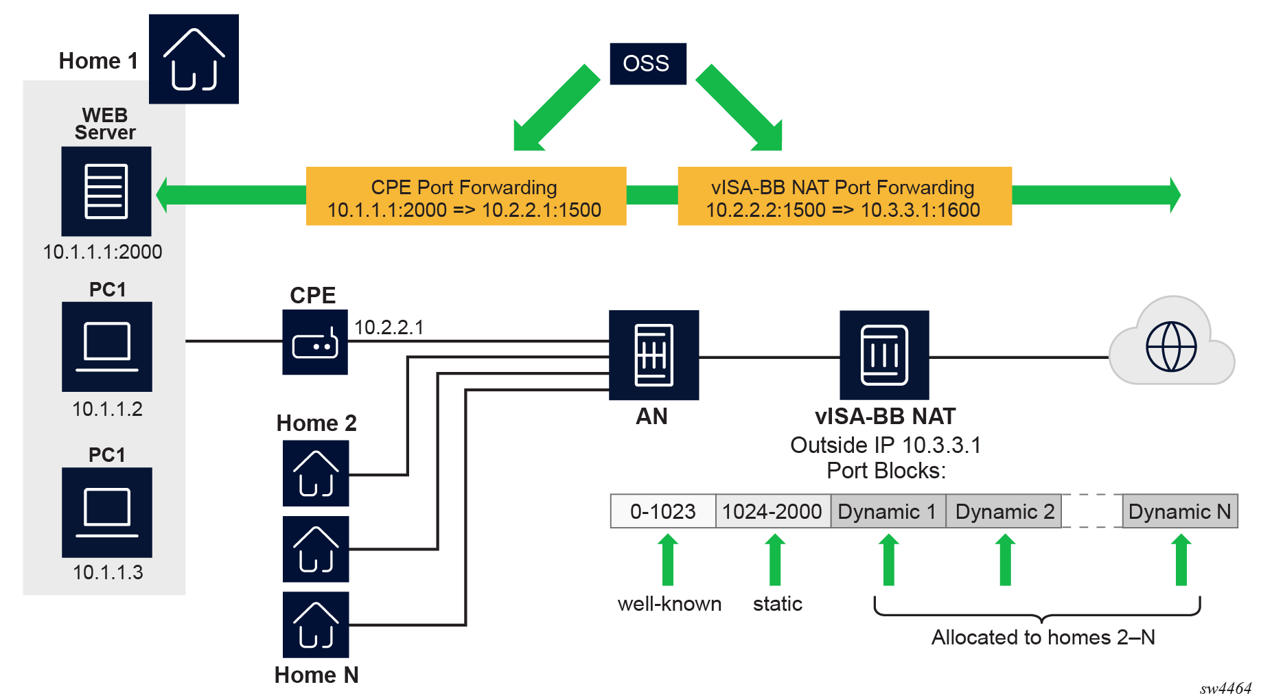
The outside IP address is always shared for the NAT subscriber with a port forward (static or via PCP) and the dynamically allocated port block, insofar as the port from the port forward is in the range >1023. This behavior can lead to starvation of dynamic port blocks for the subscriber. An example for this scenario is shown in Dynamic port block starvation in LSN.
-
A static port forward for the WEB server in Home 1 is allocated in the CPE and the vISA-BB NAT application. At the time of static port forward creation, no other dynamic port blocks for Home 1 exist (PCs are powered off).
-
Assume that the outside IP address for the newly created static port forward in the vISA-BB is 10.3.3.1.
-
Over time dynamic port blocks are allocated for a number of other homes that share the same outside IP address, 10.3.3.1. Eventually those dynamic port block allocations exhaust all dynamic port block range for the address 10.3.3.1.
-
After the dynamic port blocks are exhausted for outside IP address 10.3.3.1, a new outside IP address (for example, 10.3.3.2) is allocated for additional homes.
Eventually the PCs in Home 1 come to life and they try to connect to the Internet. Because of the dynamic port block exhaustion for the IP address 10.3.3.1 (that is mandated by static port forward – Web Server), the dynamic port block allocation fails and consequently, the PCs are not able to access the Internet. There is no additional attempt within the vISA-BB NAT to allocate another outside IP address. In the vISA-BB NAT, there is no distinction between the PCs in Home 1 and the Web Server when it comes to source IP address. They both share the same source IP address 10.2.2.1 on the CPE.
The solution for this is to reserve a port block (or blocks) during the static port forward creation for the specific subscriber.
To prevent starvation of dynamic port blocks for the NAT subscribers that use port forwards, a dynamic port block (or blocks) is reserved during the lifetime of the port forward. Those reserved dynamic port blocks are associated with the same NAT subscriber that created the port forward. However, a log would not be generated until the dynamic port block is actually used and mapping within that block are created.
At the time of the port forward creation, the dynamic port block is reserved in the following fashion:
-
If the dynamic port block for the NAT subscriber does not exist, then a dynamic port block for the NAT subscriber is reserved. No log for the reserved dynamic port block is generated until the dynamic port block starts being used (mapping created because of the traffic flow).
-
If the corresponding dynamic port block already exists, it is reserved even after the last mapping within the last port block had expired.
The reserved dynamic port block (even without any mapping) continues to be associated with the NAT subscriber as long as the port forward for the NAT subscriber is present. The log (syslog or RADIUS) is generated only when there is not active mapping within the dynamic port block and all port forwards for the NAT subscriber are deleted.
Additional considerations with dynamic port block reservation:
-
The port block reservation should be triggered only by the first port forward for the NAT subscriber. The subsequent port forwards do not trigger additional dynamic port block reservation.
-
Only a single dynamic port block for the NAT subscriber is reserved (that is, no multiple port-block reservations for the NAT subscriber are possible).
-
This feature is enabled with the following commands:
- MD-CLI
configure router nat outside pool port-forwarding dynamic-block-reservation configure service vprn nat outside pool port-forwarding dynamic-block-reservation - classic
CLI
configure router nat outside pool port-forwarding-dyn-block-reservation
configure service vprn nat outside pool port-forwarding-dyn-block-reservation
These commands can be enabled only if the maximum number of configured port blocks per outside IP is greater or equal then the maximum configured number of NAT subscribers per outside IP address. This guarantees that all NAT subscribers (up to the maximum number per outside IP address) configured with port forwards can reserve a dynamic port block.
- MD-CLI
-
If the port-reservation is enabled while the outside pool is operational and NAT subscriber's traffic is already present, the following two cases must be considered:
-
The configured number of NAT subscribers per outside IP is less or equal than the configured number of port blocks per outside IP address (this is permitted) but all dynamic port blocks per outside IP address are occupied at the moment when port reservation is enabled. This leaves existing NAT subscribers with port forwards that do not have any dynamic port blocks allocated (orphaned NAT subscribers), unable to reserve dynamic port blocks. In this case the orphaned NAT subscribers must wait until dynamic port blocks allocated to the NAT subscribers without port forwards are freed.
-
The configured number of NAT subscribers per outside IP is greater than the configured number of port blocks per outside IP address. In addition, all dynamic port blocks per outside IP address are allocated. Before the port reservation is even enabled, the NAT subscriber-limit per outside IP address must be lowered (by configuration) so that it is equal or less than the configured number of port blocks per outside IP address. This action causes random deletion of NAT mappings that do not have any port forwards. Such NAT mappings are deleted until the number of NAT subscriber falls below the newly configured subscriber limit. NAT subscribers with static port forwards are not deleted, regardless of the configured subscriber-limit number. When the number of NAT subscribers is within the newly configured NAT subscriber limit, the port-reservation can take place under the condition that the dynamic port blocks are available. If specific NAT subscribers with port forwards have more than one dynamic port block allocated, the orphaned NAT subscribers must wait for those additional dynamic port blocks to expire and consequently be released.
-
Association between NAT subscribers and IP addresses in a NAT pool
A NAT subscriber can allocate ports on a single outside IP address or multiple IP addresses in a NAT pool. Nokia recommends that NAT subscribers allocate ports from a single outside IP address. If this IP address runs out of ports, the NAT subscriber runs out of ports. In other words, there is no attempt for a new port to be allocated from a different outside IP address. This method of address allocation to a NAT subscriber is referred to as Paired Address Pooling and is the default behavior in SR OS.
The alternative method of port allocation involves port exhaustion on the originally allocated IP address. An attempt is made to allocate ports from another IP addresses that has free ports available. This results in a NAT subscriber be associated with multiple outside IP addresses. This method is referred to as Arbitrary Address Pooling and can be optionally enabled in SR OS. See RFC 7857, Section 4 for more information.
Arbitrary address pooling may offer more efficient allocations of port-blocks across outside IP address in a NAT pool, but it may negatively affect some applications. For example, an application may require two channels for communication, a control channel and a data channel, each on a different source port from the client perspective on the inside of the NAT. The communication channel may be established on the outside address IP1 and outside port X. If port X is the last free port on the IP1, the SR OS attempts to allocate the next port Y for the data channel from a different outside address, IP2. If the application is robust enough to accept communication from the same client on two different IP addresses, there are no issues. However, some applications may not support this scenario and the communication fails.
Arbitrary address pooling implies the following:
-
The NAT subscriber limit per outside IP address loses its meaning because the NAT subscriber can now be associated with multiple IP addresses. Hence, the following command cannot be set:
- MD-CLI
configure router nat outside pool large-scale subscriber-limit - classic
CLI
configure router nat outside pool subscriber-limit
- MD-CLI
-
The number of port blocks configured in a NAT policy using the following command is the aggregate limit that a NAT subscriber can be allocated across multiple outside IP addresses.
configure service nat nat-policy block-limit -
Reserving a port block by SPF configuration (when an SPF is configured before any port blocks are allocated to the NAT subscriber) is not supported. In other words, the following commands are not supported:
MD-CLI
configure router nat outside pool port-forwarding dynamic-block-reservationclassic CLIconfigure router nat outside pool port-forwarding-dyn-block-reservation -
Arbitrary address pooling is not supported in Layer 2–aware NAT.
Use the following command to show NAT LSN information for the NAT subscriber.
show service nat lsn-subscribers subscriberThe asterisk (*) next to the IP address field in the output indicates that additional outside IP addresses are associated with this NAT subscriber in this pool.
===============================================================================
NAT LSN subscribers
===============================================================================
Subscriber                  : [LSN-Host@192.168.1.1]
NAT policy                  : nat-policy-lsn-deterministic
Subscriber ID               : 276824064
-------------------------------------------------------------------------------
Type                        : classic-lsn-sub
Inside router               : "Base"
Inside IP address prefix    : 192.168.1.1/32
ISA NAT group               : 1
ISA NAT group member        : 1
Outside router              : 4
Outside IP address          : 192.0.0.1*
Use the detailed version of the command to see additional outside IP addresses and port blocks.
Timeouts
Creating a NAT mapping is only one half of the problem – removing a NAT mapping at the appropriate time maximizes the shared port resource. Having ports mapped when an application is no longer active reduces solution scale and may impact the customer experience should they exhaust their port range block. The NAT application provides timeout configuration for TCP, UDP and ICMP.
TCP state is tracked for all TCP connections, supporting both three-way handshake and simultaneous TCP SYN connections. Separate and configurable timeouts exist for TCP SYN, TCP transition (between SYN and Open), established and time-wait state. Time-wait assassination is supported and enabled by default to quickly remove TCP mappings in the TIME WAIT state.
UDP does not have the concept of connection state and is subject to a simple inactivity timer. Company-sponsored research into applications and NAT behavior suggested some applications, like the BitTorrent Distributed Hash Protocol (DHT) can make a large number of outbound UDP connections that are unsuccessful. Instead of waiting the default five (5) minutes to time these out, the 7705 SAR Gen 2 NAT application supports an udp-initial timeout which defaults to 15 seconds. When the first outbound UDP packet is sent, the 15 second time starts – it is only after subsequent packets (inbound or outbound) that the default UDP timer becomes active, greatly reducing the number of UDP mappings.
NAT pool addresses and ICMP Echo Request/Reply (ping)
The outside IPv4 addresses in a NAT pool can be configured to answer pings. ICMPv4 Echo Requests are answered with ICMPv4 Echo Replies.
In 1:1 NAT, ICMP Echo Requests are propagated to the host on the inside. The host identified by a NAT binding then answers the ping.
In Network Address Port Translation (NAPT), ICMP Echo Requests are not propagated to the hosts behind the NAT. Instead, the reply is issued by the SR OS from the ESA or ISA.
In Layer 2-aware NAT, use the following command to configure how replies from outside IP addresses are handled:
- MD-CLI
configure router nat outside pool l2-aware port-block-extension - classic
CLI
configure router nat outside pool port-block-extensions
In NAPT, the behavior is as follows:
-
In Layer 2–aware NAT when port-block-extensions is disabled, the reply from an outside IP address is generated only when the IP address has at least one host (binding) behind it.
-
In Layer 2–aware NAT when port-block-extensions is enabled, the reply from an outside IP address is generated regardless if a binding is present.
-
In LSN, the reply from an outside IP address is generated regardless if a binding is present.
For security reasons, the ICMP Echo Reply functionality is disabled by default. Use the following command to enable ICMP Echo Reply functionality.
configure router nat outside pool icmp-echo-replyThis functionality is on a per-pool basis and it can be configured online while the pool is enabled.
One-to-one (1:1) NAT
In 1:1 NAT, each source IP address is translated in 1:1 fashion to a corresponding outside IP address. However, the source ports are passed transparently without translation.
The mapping between the inside IP addresses and outside IP addresses in 1:1 NAT supports two modes:
dynamic
The user can specify the outside IP addresses in the pool, but the exact mapping between the inside IP address and the configured outside IP addresses is performed dynamically by the system in a semi-random fashion.
static
The mappings between IP addresses are configurable and they can be explicitly set.
The dynamic version of 1:1 NAT is protocol dependent. Only TCP/UDP/ICMP protocols are allowed to traverse such NAT. All other protocols are discarded, with the exception of PPTP with ALG. In this case, only GRE traffic associated with PPTP is allowed through dynamic 1:1 NAT.
The static version of 1:1 NAT is protocol agnostic. This means that all IP based protocols are allowed to traverse static 1:1 NAT.
The following points are applicable to 1:1 NAT:
Even though source ports are not being translated, the state maintenance for TCP and UDP traffic is still performed.
Traffic can be initiated from outside toward any statically mapped IPv4 address.
1:1 NAT can be supported simultaneously with NAPT (classic non 1:1 NAT) within the same inside routing context. This is accomplished by configuring two separate NAT pools, one for 1:1 NAT and the other for non 1:1 NAPT.
Static 1:1 NAT
In static 1:1 NAT, inside IP addresses are statically mapped to the outside IP addresses. This way, devices on the outside can predictably initiate traffic to the devices on the inside.
The following example shows a static 1:1 NAT configuration.
Static 1:1 NAT configuration (MD-CLI)
[gl:/configure router "Base" nat inside large-scale nat44 deterministic]
A:admin@sr-1s# info
    address-map 10.10.0.220 to 10.10.0.220 nat-policy "cgn44" {
        outside-range 192.168.255.206
    }
    address-map 10.10.0.221 to 10.10.0.221 nat-policy "cgn44" {
        outside-range 192.168.255.207
    }
    address-map 10.10.0.222 to 10.10.0.222 nat-policy "cgn44" {
        outside-range 192.168.255.208
    }
    address-map 10.10.0.223 to 10.10.0.223 nat-policy "cgn44" {
        outside-range 192.168.255.209
    }
Static 1:1 NAT configuration (classic CLI)
A:node-2>config>router>nat>inside>deterministic# info
----------------------------------------------
            address-map 10.10.0.220 to 10.10.0.220 subscriber-type classic-lsn-sub nat-policy "cgn44" create
                outside-range 192.168.255.206
            exit
            address-map 10.10.0.221 to 10.10.0.221 subscriber-type classic-lsn-sub nat-policy "cgn44" create
                outside-range 192.168.255.207
            exit
            address-map 10.10.0.222 to 10.10.0.222 subscriber-type classic-lsn-sub nat-policy "cgn44" create
                outside-range 192.168.255.207
            exit
            address-map 10.10.0.223 to 10.10.0.223 subscriber-type classic-lsn-sub nat-policy "cgn44" create
                outside-range 192.168.255.206
            exit
----------------------------------------------
Static mappings are configured according to the map statements:
-
In the MD-CLI, the map statement must be configured by the user, but the following command can be used to produce system-generated maps.
The preceding command outputs a set of system-generated map statements. The map command options can then be copied and pasted into an MD-CLI candidate configuration by the user.tools perform nat deterministic calculate-maps -
In classic CLI, the map statement can be configured manually by the user or automatically by the system.
IP addresses from the automatically-generated map statements are sequentially mapped into available outside IP addresses in the pool:
-
The first inside IP address is mapped to the first available outside IP address from the pool.
-
The second inside IP address is mapped to the second available outside IP address from the pool.
The following mappings apply to the preceding example.
| Inside IP address | Outside IP address |
|---|---|
|
10.10.0.220 |
192.168.255.206 |
|
10.10.0.221 |
192.168.255.207 |
|
10.10.0.222 |
192.168.255.208 |
|
10.10.0.223 |
192.168.255.209 |
Protocol-agnostic behavior
Although static 1:1 NAT is protocol agnostic, the state maintenance for TCP and UDP traffic is still required to support ALGs. Therefore, the existing scaling limits related to the number of supported flows still apply.
The following example shows protocol-agnostic behavior in 1:1 NAT is a property of a NAT pool.
Protocol-agnostic behavior configuration (MD-CLI)
[ex:/configure router "Base" nat outside]
A:admin@node-2# info
    pool "one-to-one" {
        admin-state enable
        type large-scale
        nat-group 1
              mode one-to-one
        applications {
            agnostic true
        }
        port-forwarding {
            range-start 0
            range-end 0
        }
        port-reservation {
            port-blocks 1
        }
        large-scale {
            subscriber-limit 1
            }
            deterministic {
                port-reservation 65325
            }
        address-range 192.168.2.0 end 192.168.2.10 {
        }
    }
Protocol-agnostic behavior configuration (classic CLI)
A:node-2>config>router>nat>outside# info
----------------------------------------------
               pool "one-to-one" nat-group 1 type large-scale applications agnostic create
                    no shutdown
                    port-reservation blocks 1
                    port-forwarding-range 0 0
                    subscriber-limit 1
                    deterministic
                        port-reservation 65325
                    exit
                    mode one-to-one
                    address-range 192.168.2.0 192.168.2.10 create
                    exit
                exit
----------------------------------------------
The application agnostic command is a pool create-time command. This command automatically pre-sets the following pool command options:
-
mode is set to one-to-one
-
port forwarding range start is set to 0
-
port forwarding range end is set to 0
-
number of port reservation blocks is set to 1
-
the subscriber limit is set to 1
-
the deterministic port reservation is set to 65325, which configures the pool to operate in static (or deterministic) mode
When pre-set, these command options cannot be changed while the pool is operating in protocol agnostic mode.
Modification of parameters in static 1:1 NAT
In classic CLI only, command options in the static 1:1 NAT can be changed according to the following rules:
-
The deterministic pool must be in a no shutdown state when a prefix or a map command in deterministic NAT is added or removed.
-
All configured prefixes referencing the pool via the NAT policy must be deleted (unconfigured) before the pool can be shut down.
-
Map statements can be modified only when prefix is shutdown state. All existing map statements must be removed before the new ones are created.
These rules do not apply in MD-CLI.
NAT-policy selection
The traffic match criteria used in the selection of specific NAT policies in static 1:1 NAT (the deterministic part of the configuration) must not overlap with traffic match criteria that is used in the selection of a specific NAT policy used in filters or in destination-prefix statement (these are used for traffic diversion to NAT). Otherwise, traffic is dropped in ISA.
A specific NAT policy in this context refers to a non-default NAT policy, or a NAT policy that is directly referenced in a filter, in a destination prefix or a deterministic prefix.
The following example is used to clarify this point.
NAT policy selection (MD-CLI)
[ex:/configure router "Base" nat inside large-scale]
A:admin@node-2# info
    nat44 {
        max-subscriber-limit 128
        destination-prefix 192.0.2.0/24 {
            nat-policy "pol-2"
        }
        deterministic {
            prefix-map 10.10.10.0/24 nat-policy "pol-1" {
                map 10.10.10.0 to 10.10.10.255 {
                    first-outside-address 192.168.0.1
                }
            }
        }
    }
NAT policy selection (classic CLI)
A:node-2>config>router>nat>inside# info
----------------------------------------------
                destination-prefix 192.0.2.0/24 nat-policy "pol-2"
                classic-lsn-max-subscriber-limit 128
                deterministic
                    prefix-map 10.10.10.0/24 subscriber-type classic-lsn-sub nat-policy "pol-1" create
                        shutdown
                        map start 10.10.10.0 end 10.10.10.255 to 192.168.0.1
                    exit
                exit
----------------------------------------------
In the preceding example:
-
Traffic is diverted to NAT using specific nat-policy pol-2.
-
The deterministic (source) prefix 10.10.10.0/24 is configured to be mapped to nat-policy pol-1 specifically which points to protocol agnostic 1:1 NAT pool.
-
Packets received in the ISA have a source IP of 10.10.10.0/24 and a destination IP of 192.0.2.0/24.
-
If no NAT mapping for this traffic exists in the ISA, a NAT policy (and with this, the NAT pool) must be determined to create the mapping. Traffic is diverted to NAT using NAT policy pol-2, while the deterministic mapping suggests that the NAT policy pol-1 should be used (this is a different pool from the one referenced in NAT policy pol-2). Because of the specific NAT policy conflict, traffic is dropped in the ISA.
To successfully pass traffic between two subnets through NAT while simultaneously using static 1:1 NAT and regular LSN44, a default (non-specific) NAT policy can be used for regular LSN44.
A specific NAT policy (in a filter, destination-prefix command, or in deterministic prefix-map command) always takes precedence over a default NAT policy. However, traffic that matches classification criteria (in a filter, destination-prefix command, or a deterministic prefix-map command) that leads to multiple specific NAT policies, is dropped.
In this case, the four hosts from the prefix 10.10.10.0/24 are mapped in 1:1 fashion to 4 IP addresses from the pool referenced in the specific NAT policy pol-1, while all other hosts from the 10.10.10.0/24 network are mapped to the NAPT pool referenced by the default NAT policy pol-2. In this way, a NAT policy conflict is avoided.
Mapping timeout
Static 1:1 NAT mappings are explicitly configured, and therefore, their lifetime is tied to the configuration.
Logging
The logging mechanism for static mapping is the same as in Deterministic NAT. Configuration changes are logged via syslog and enhanced with reverse querying on the system.
Restrictions
Static 1:1 NAT is supported only for LSN44. There is no support for DS-Lite/NAT64 or Layer 2–aware NAT.
ICMP
In 1:1 NAT, specific ICMP messages contain an additional IP header embedded in the ICMP header. For example, when the ICMP message is sent to the source because of the inability to deliver datagram to its destination, the ICMP generating node includes the original IP header of the packet plus 64bits of the original datagram. This information helps the source node to match the ICMP message to the process associated with this message.
When these messages are received in the downstream direction (on the outside), 1:1 NAT recognizes them and changes the destination IP address not only in the outside header but also in the ICMP header. In other words, a lookup in the downstream direction is performed in the ISA to determine if the packet is ICMP with a specific type. Depending on the outcome, the destination IP address in the ICMP header is changed (reverted to the original source IP address).
Messages carrying the original IP header within ICMP header are:
Destination Unreachable Messages (Type 3)
Time Exceeded Message (Type 11)
Parameter Problem Message (Type 12)
Source Quench Message (Type 4)
LSN – multiple NAT policies per inside routing context
Multiple NAT policies per inside routing context
The selection of the NAT pool and the outside routing context is performed through the NAT policy. Multiple NAT policies can be used within an inside routing context. This feature effectively allows selective mapping of the incoming traffic within an inside routing context to different NAT pools (with different mapping properties, such as port-block size, NAT subscriber-limit per pool, address range, port-forwarding range, deterministic vs non-deterministic behavior, port-block watermarks, and so on) and to different outside routing contexts. NAT policies can be configured:
-
via filters as part of the action nat command
-
via routing with the destination-prefix command within the inside routing context
The concept of the NAT pool selection mechanism based on the destination of the traffic via routing is shown in Pool selection based on traffic destination.
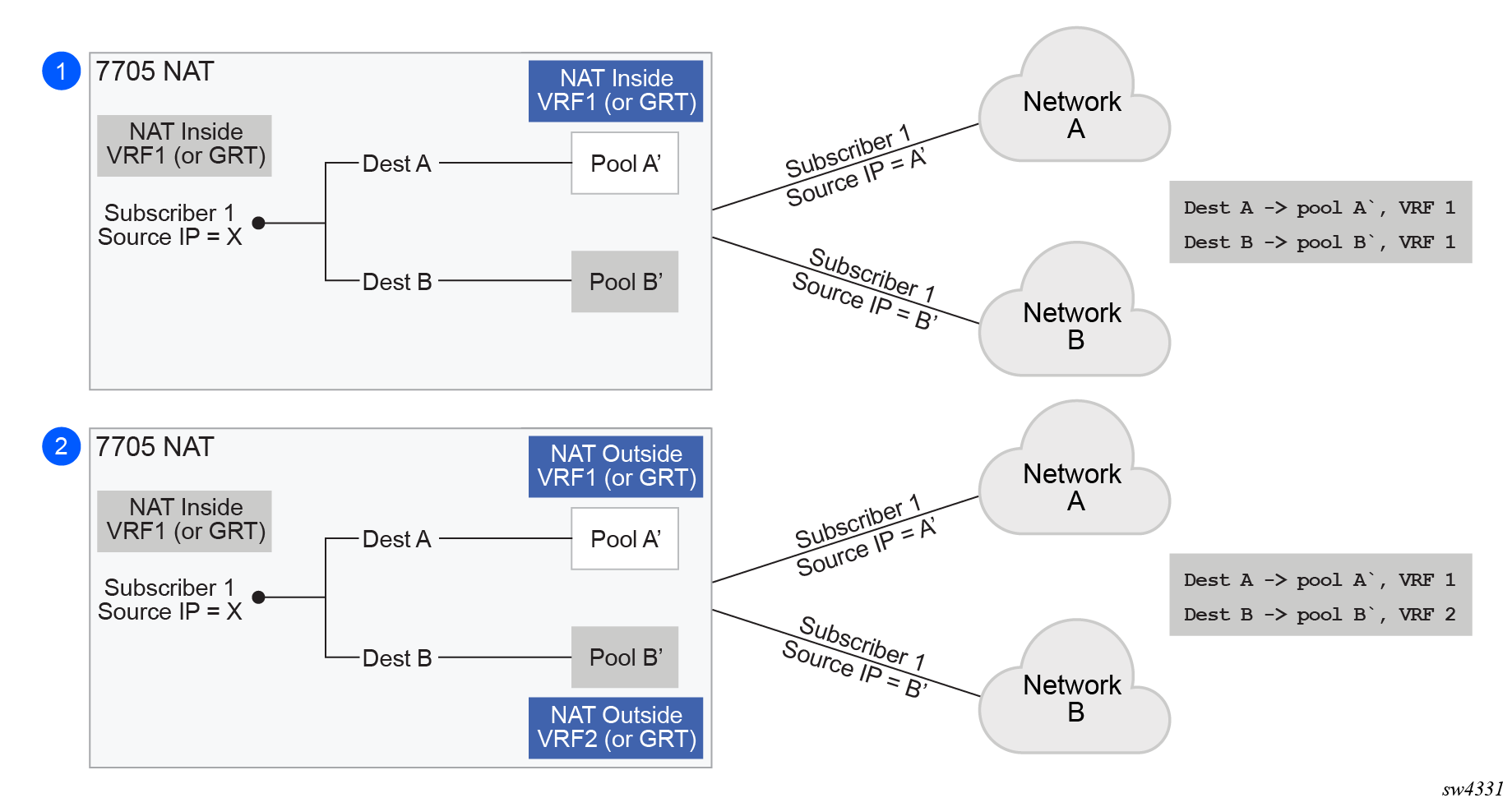
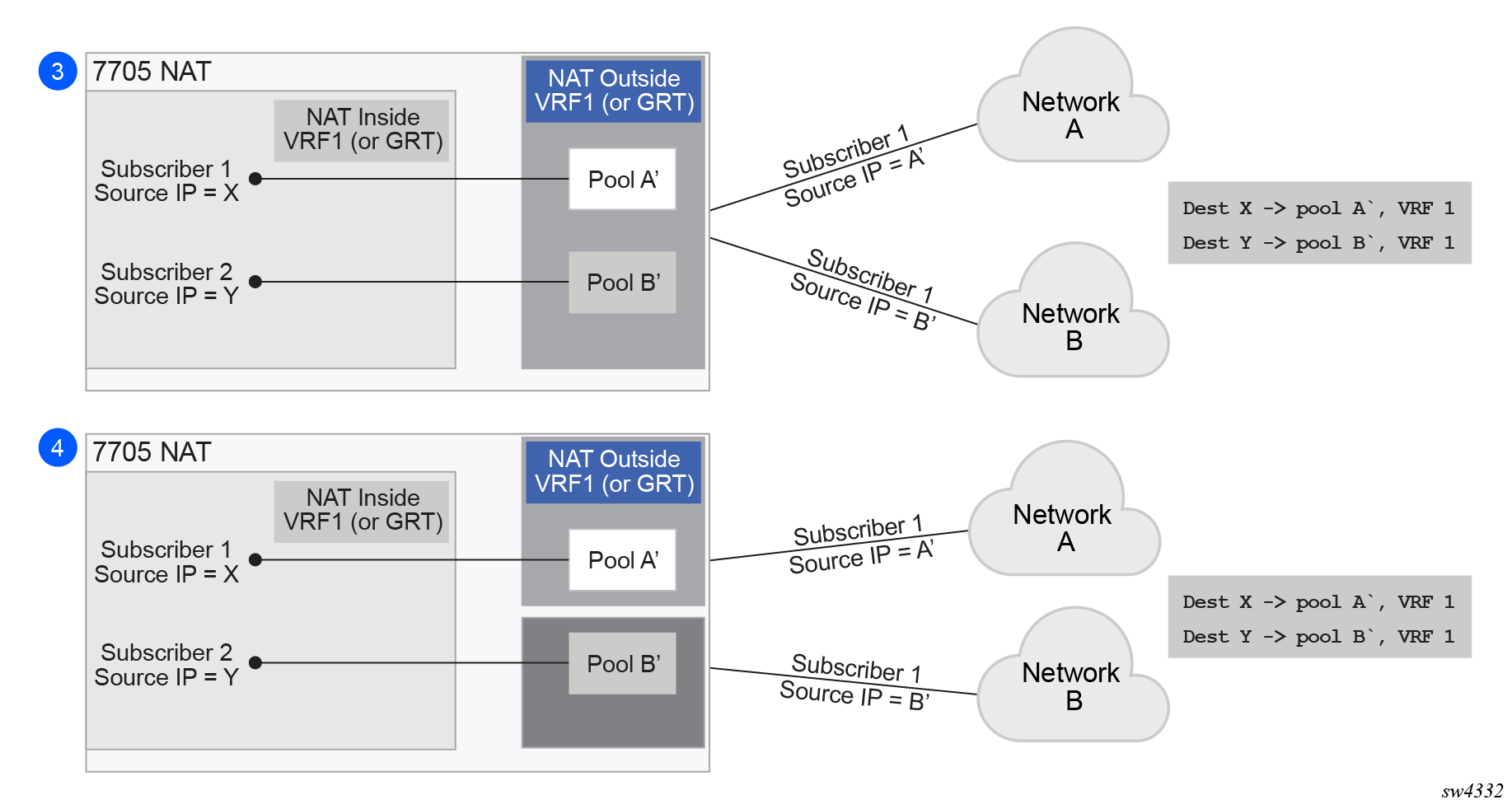
Diversion of the traffic to NAT based on the source of the traffic is shown in NAT pool selection based on the inside source IP address.
Only the filter-based diversion solution is supported for this case. The filter-based solution can be extended to a five tuple matching criteria.
The following considerations must be taken into account when deploying multiple NAT policies per inside routing context:
-
The inside IP address can be mapped into multiple outside IP addresses based on the traffic destination. The relationship between the inside IP and the outside IP is 1:N.
-
In case where the source IP address is selected as a matching criteria for a NAT policy (or pool) selection, the inside IP address always stays mapped to the same outside IP address (relationship between the inside IP and outside IP address is, in this case, 1:1)
-
Static Port Forwards (SPF); each SPF can be created only in one pool. This means that the pool (or NAT policy) must be an input parameter for SPF creation.
Routing approach for NAT diversion
- MD-CLI
configure service vprn nat inside large-scale nat44 destination-prefix configure router nat inside large-scale nat44 destination-prefix - classic
CLI
configure service vprn nat inside destination-prefix
configure router nat inside destination-prefix
In other words, the upstream traffic is NAT’d only if it matches a preconfigured destination IP prefix. The destination-prefix command creates a static route in the routing table of the inside routing context. This static route diverts all traffic with the destination IP address that matches the created entry, toward the MS-ISA. The NAT function itself is performed when the traffic is in the correct context in the MS-ISA.
The following example displays the configuration of multiple NAT policies per inside routing context with routing based diversion to NAT.
Configuring multiple NAT policies per inside routing context (MD-CLI)
[ex:/configure service vprn "66"]
A:admin@node-2# info
    customer "1"
    nat {
        inside {
            large-scale {
                nat44 {
                    destination-prefix 10.20.10.0/24 {
                        nat-policy "policy-1"
                    }
                    destination-prefix 10.30.30.0/24 {
                        nat-policy "policy-1"
                    }
                    destination-prefix 10.40.40.0/24 {
                        nat-policy "policy-2"
                    }
                }
            }
        }
    }

[ex:/configure router "Base"]
A:admin@node-2# info
    nat {
        inside {
            large-scale {
                nat44 {
                    max-subscriber-limit 256
                    destination-prefix 10.20.10.0/24 {
                        nat-policy "policy-1"
                    }
                    destination-prefix 10.30.30.0/24 {
                        nat-policy "policy-1"
                    }
                    destination-prefix 10.40.40.0/24 {
                        nat-policy "policy-2"
                    }
                }
            }
        }
    }
Configuring multiple NAT policies per inside routing context (classic CLI)
A:node-2>config>service>vprn# info
----------------------------------------------
            shutdown
            nat
                inside
                    destination-prefix 10.20.10.0/24 nat-policy "policy-1"
                    destination-prefix 10.30.30.0/24 nat-policy "policy-1"
                    destination-prefix 10.40.40.0/24 nat-policy "policy-2"
                exit
            exit
----------------------------------------------

A:node-2>config>router# info
...
#--------------------------------------------------
echo "NAT Configuration"
#--------------------------------------------------
            shutdown
            nat
                inside
                    destination-prefix 10.20.10.0/24 nat-policy "policy-1"
                    destination-prefix 10.30.30.0/24 nat-policy "policy-1"
                    destination-prefix 10.40.40.0/24 nat-policy "policy-2"
                exit
            exit
----------------------------------------------
Different destination prefixes can reference a single NAT policy (policy-1 in this case).
- MD-CLI
configure service vprn nat inside large-scale configure router nat inside large-scale - classic
CLI
configure service vprn nat inside
configure router nat inside
After the destination-prefix command referencing the NAT policy is configured, an entry in the routing table is created that directs the traffic to the MS-ISA.
Filter-based approach
configure filter ip-filter entry matchconfigure filter ip-filter entry action nat [nat-policy nat-policy-name]The association with the NAT policy is made after the filter is applied to the SAP.
Scaling considerations
Each subscriber using multiple policies is counted as one NAT subscriber for the inside resources scaling limits (such as the number of subscribers per MS-ISA), and counted as one subscriber per (subscriber and policy combination) for the outside limits (subscriber-limit subscribers per IP; port-reservation port/block reservations per subscriber).
The default NAT policy is counted toward the maximum polices per NAT subscriber.
Watermarks
Watermarks can be configured to monitor the actual usage of sessions, ports, and port blocks.
For each watermark, a high and a low value must be set. When the high threshold value is crossed in the upward direction, an event is generated (SNMP trap), notifying the user that a NAT resource may be approaching exhaustion. When the low threshold value is crossed in the downward direction, a similar event is generated (clearing the first event), notifying the user that the resource utilization has dropped below the low threshold value.
Watermarks can be defined on the NAT group, pool, and policy level.
-
NAT group
Watermarks can be placed to monitor the total number of sessions on an MDA.
-
NAT pool on each NAT group member
Watermarks can be placed to monitor the port and port-block occupancy in a pool within each NAT group member.
-
NAT policy
In the policy, the user can define watermarks on port usage.
Port forwards
Port forwards allow devices on the public side of NAT (NAT outside) to initiate sessions toward those devices, usually servers, that are hidden behind NAT (NAT inside). Another term for port forwards is NAT pinhole.
A port forward represents a previously created (before any traffic is received from the inside) mapping between a TCP/UDP port on the outside IP address and a TCP/UDP port on the inside IP address assigned to a device behind the NAT. This mapping can be created statically by configuration using CLI, MIB, YANG, or NETCONF). Port forwards are supported only in NAT pools in Network Address and Port Translation (NAPT) mode. NAT pools in 1:1 mode do not support configured port forwards because, by default, the pools allow traffic from the outside to the inside and this cannot be disabled. Pools in 1:1 mode (whether protocol agnostic) do not perform port translation; therefore the inside and outside always match.
The forwarded ports are allocated from a dedicated port range outside of the port blocks allocated to individual NAT subscribers. There are two ranges dedicated to port forwards in NAT:
-
well-known ports (1 to 1023)
This range is always enabled and cannot be disabled in NAT pools that support configured port forwards (non 1:1 NAT pools).
-
ports from the ephemeral port range (1025 to 65535)
Port forwards from the ephemeral port space must be explicitly enabled by configuration. They are allocated from a contiguous block of ports where upper and lower limits are defined. Ports reserved for port forwards allocated in the ephemeral port space are also referred to as wildcard ports.
Port forwarding ranges (well-known ports and wildcard ports) are shared by all NAT subscribers on a specific outside IP address. Port blocks that are individually assigned to the NAT subscriber cannot be allocated from the port forwarding range. The wildcard port forwarding range can be configured only when the pool is administratively disabled.
Static port forwards
Use the command options in the following command to manage port forwarding for Large Scale NAT (LSN):
- MD-CLI, NETCONF, and classic CLI
In the MD-CLI, NETCONF, and classic CLI, use the options under the following command to manage NAT Static Port Forwards (SPFs). This command enables large-scale NAT port forwarding actions.
tools perform nat port-forwarding-action lsnFor the preceding tools command, if you do not explicitly configure the following optional fields, the system selects them automatically:- port number – number of the source port
- outside IP – IPv4 address for the outside IP address
- outside-port number – number of the outside port
- NAT policy – name of the NAT policy
If the preceding tools command is configured to manage SPFs and preserve SPFs across reboots, you must use the following command to enable persistency of the SPF. With persistency enabled, SPF configuration is stored on the compact flash.
configure system persistence nat-port-forwarding -
classic CLI
In the classic CLI, you can manage SPFs through the preceding tools command or the following configuration command. This command creates NAT static port forwards for LSN44.
configure service nat port-forwarding lsn
Manage the SPFs using the tools command (MD-CLI)
[/tools perform nat port-forwarding-action]
A:admin@node-2# lsn add router 100 ip 10.2.3.4 protocol udp lifetime infinite outside-port 888

[/]
*A:node-2# configure system persistence nat-port-forwarding location cf3

[/]
*A:node-2# tools dump persistence nat-port-forwarding
----------------------------------------
Persistence Info
----------------------------------------
Client : nat-fwds
File Info :
Filename : cf3:\nat_fwds.002
File State : CLOSED (Not enough space on disk)
Subsystem Info :
Nbr Of Registrations : 524288
Registrations In Use : 2
Subsystem State : NOK
Manage the SPFs using the tools command (classic CLI)
*A:node-2# tools perform nat port-forwarding-action lsn create router 100
ip 10.2.3.4 protocol udp lifetime infinite outside-port 888
*A:node-2# configure system persistence nat-port-forwarding location cf3:
*A:node-2# tools dump persistence nat-port-forwarding
----------------------------------------
Persistence Info
----------------------------------------
Client : nat-fwds
File Info :
Filename : cf3:\nat_fwds.002
File State : CLOSED (Not enough space on disk)
Subsystem Info :
Nbr Of Registrations : 524288
Registrations In Use : 2
Subsystem State : NOK
Manage the SPFs using the configuration command (classic CLI)
The following command only applies for the classic CLI.
*A:node-2>config>service>nat>fwd# lsn router 101 ip 11.11.13.7 protocol udp port 12345 outside-ip 130.0.255.254 outside-port 3171 nat-policy "pol1_for_2001-pool-0"
You can specify a force option that is applicable only to LSN pools with flexible port allocations where the dynamic ports in this pool are allocated individually instead of port blocks. The dynamic ports are interleaved with Static Port Forwards (SPFs). This creates increased possibility for a collision between the dynamically-allocated port and the requested SPF during an SPF request.
For instance, if a user requests port X on a public IP address Y, there is a chance that port X is already in use because of the dynamic allocation.
To resolve such conflicts, use the force option to ensure that the requested SPF has higher priority, allowing it to preempt an existing dynamically-allocated port. This action overwrites the previous port mapping and deletes all associated sessions.
If you omit the force option in such a scenario, the static-port allocation fails. The force option can only preempt dynamically-allocated ports and does not affect pre-existing SPFs.
Modifying active NAT prefix list or NAT classifier via CLI
Modifying active NAT prefix list or NAT classifier describes the outcome when the active NAT prefix list or NAT classifier is modified using CLI.
| Action | Outcome | Remarks |
|---|---|---|
| LSN | ||
|
CLI – Modifying prefix in the NAT prefix list |
Changing the prefix in the NAT prefix list internally re-subnets the outside IP address space. |
NAT prefix list is used with multiple NAT policies in Layer 2–aware NAT and for downstream internal subnet in dNAT-only scenario for LSN. The prefix can be modified (added, removed, remapped) at any time in the NAT prefix list. In the classic CLI, the NAT policy must be first administratively disabled via CLI. |
|
CLI – Removing/adding NAT policy in the NAT prefix list |
Not Applicable |
— |
|
CLI – Removing, adding, or replacing the NAT policy in sub-profile |
Not Applicable |
— |
|
CLI – Removing, adding, or replacing the NAT prefix list under the rtr/nat/inside |
Internally re-subnet, no effect on the flows |
— |
NAT logging
LSN logging is extremely important to operators who are required by their organizations to track source of suspicious activities.
The 7705 SAR Gen 2 supports several modes of logging for LSN applications. Choosing the right logging model depends on the required scale, simplicity of deployment and granularity of the logged data.
For most purposes logging of allocation or de-allocation of outside port-blocks and outside IP address along with the corresponding LSN subscriber and inside service-id is sufficient.
Syslog, SNMP, local-file logging
The simplest form of NAT logging is via the logging facility in the 7705 SAR Gen 2, commonly called logger. Each port-block allocation or de-allocation event is recorded and send to the system logging facility (logger). Such an event can be:
-
recorded in the system memory as part of regular logs
-
written to a local file
-
sent to an external server by a syslog facility
-
sent to a SNMP trap destination
In this mode of logging, all applications in the system share the same logger.
Syslog, SNMP, and local-file logging on LSN and NAT RADIUS-based logging are mutually exclusive.
Use the options under the following context to enable syslog, SNMP, and local-file logging for NAT:
- MD-CLI
configure log log-events - classic
CLI
configure log event-control
The following output example displays relevant MIB events.
Relevant MIB events
2012 tmnxNatPlBlockAllocationLsn
2013 tmnxNatPlBlockAllocationL2Aw
Filtering LSN events to system memory
In the following example, a single port-block [1884-1888] is allocated or de-allocated for the inside IP address 10.5.5.5 which is mapped to the outside IP address 198.51.100.1. Consequently, the event is logged in the memory as shown.
Event log memory output
2 2012/07/12 16:40:58.23 WEST MINOR: NAT #2012 Base NAT
"{2} Free 198.51.100.1 [1884-1888] -- vprn10 10.5.5.5 at 2012/07/12 16:40:58"

1 2012/07/12 16:39:55.15 WEST MINOR: NAT #2012 Base NAT
"{1} Map  198.51.100.1 [1884-1888] -- vprn10 10.5.5.5 at 2012/07/12 16:39:55"
When the needed LSN events are enabled for logging via the following configuration, they can be logged to memory through standard log ID 99 or be filtered with a custom log ID, such as in this example that follows (log-id 5).
Enable LSN events for logging (MD-CLI)
[ex:/configure log]
A:admin@node-2# info
    log-events {
        nat event tmnxNatPlL2AwBlockUsageHigh {
            generate false
            throttle false
        }
        nat event tmnxNatIsaMemberSessionUsageHigh {
            generate false
            throttle false
        }
        nat event tmnxNatPlLsnMemberBlockUsageHigh {
            generate false
            throttle false
        }
        nat event tmnxNatL2AwSubIcmpPortUsageHigh {
            generate false
            throttle false
        }
        nat event tmnxNatL2AwSubUdpPortUsageHigh {
            generate false
            throttle false
        }
        nat event tmnxNatL2AwSubTcpPortUsageHigh {
            generate false
            throttle false
        }
        nat event tmnxNatL2AwSubSessionUsageHigh {
            generate false
            throttle false
        }
        nat event tmnxNatPlBlockAllocationLsn {
            generate true
        }
        nat event tmnxNatResourceProblemDetected {
            generate false
            throttle false
        }
        nat event tmnxNatResourceProblemCause {
            generate false
            throttle false
        }
        nat event tmnxNatPlLsnRedActiveChanged {
            generate false
            throttle false
        }
    }
    filter "1" {
        default-action drop
        named-entry "1" {
            action forward
            match {
                application {
                    eq nat
                }
                event {
                    eq 2012
                }
            }
        }
    }
    log-id "5" {
        filter "1"
        source {
            main true
        }
        destination {
            memory {
            }
        }
    }
Enable LSN events for logging (classic CLI)
A:node-2>config>log# info
----------------------------------------------
        filter 1
            default-action drop
            entry 1
                action forward
                match
                    application eq "nat"
                    number eq 2012
                exit
            exit
        exit
        event-control "nat" 2001 suppress
        event-control "nat" 2002 suppress
        event-control "nat" 2003 suppress
        event-control "nat" 2004 suppress
        event-control "nat" 2005 suppress
        event-control "nat" 2006 suppress
        event-control "nat" 2007 suppress
        event-control "nat" 2008 suppress
        event-control "nat" 2009 suppress
        event-control "nat" 2010 suppress
        event-control "nat" 2011 suppress
        event-control "nat" 2012 generate
        event-control "nat" 2014 suppress
        event-control "nat" 2015 suppress
        event-control "nat" 2017 suppress
        syslog 10
        exit
        log-id 5 name "5"
            filter 1
            from main
            to memory
        exit
----------------------------------------------
Use the following command to display the log event information.
show log event-control "nat" Log events output
=======================================================================
Log Events
=======================================================================
Application
 ID#    Event Name                       P   g/s     Logged     Dropped
-----------------------------------------------------------------------
   2001 tmnxNatPlL2AwBlockUsageHigh      WA  thr          0           0
   2002 tmnxNatIsaMemberSessionUsageHigh WA  thr          0           0
   2003 tmnxNatPlLsnMemberBlockUsageHigh WA  thr          0           0
   2007 tmnxNatL2AwSubIcmpPortUsageHigh  WA  thr          0           0
   2008 tmnxNatL2AwSubUdpPortUsageHigh   WA  thr          0           0
   2009 tmnxNatL2AwSubTcpPortUsageHigh   WA  thr          0           0
   2010 tmnxNatL2AwSubSessionUsageHigh   WA  thr          0           0
   2012 tmnxNatPlBlockAllocationLsn      MI  sup          0           0
   2013 tmnxNatPlBlockAllocationL2Aw     MI  sup          0           0
   2014 tmnxNatResourceProblemDetected   MI  thr          0           0
   2015 tmnxNatResourceProblemCause      MI  thr          0           0
   2016 tmnxNatPlAddrFree                MI  sup          0           0
   2017 tmnxNatPlLsnRedActiveChanged     WA  thr          0           0
   2018 tmnxNatPcpSrvStateChanged        MI  thr          0           0
   2020 tmnxNatMdaActive                 MI  thr          0           0
   2021 tmnxNatLsnSubBlksFree            MI  sup          0           0
   2022 tmnxNatDetPlcyChanged            MI  thr          0           0
   2023 tmnxNatMdaDetectsLoadSharingErr  MI  thr          0           0
   2024 tmnxNatIsaGrpOperStateChanged    MI  thr          0           0
   2025 tmnxNatIsaGrpIsDegraded          MI  thr          0           0
   2026 tmnxNatLsnSubIcmpPortUsgHigh     WA  thr          0           0
   2027 tmnxNatLsnSubUdpPortUsgHigh      WA  thr          0           0
   2028 tmnxNatLsnSubTcpPortUsgHigh      WA  thr          0           0
   2029 tmnxNatLsnSubSessionUsgHigh      WA  thr          0           0
   2030 tmnxNatInAddrPrefixBlksFree      MI  sup          0           0
   2031 tmnxNatFwd2EntryAdded            MI  sup          0           0
   2032 tmnxNatDetPlcyOperStateChanged   MI  thr          0           0
   2033 tmnxNatDetMapOperStateChanged    MI  thr          0           0
   2034 tmnxNatFwd2OperStateChanged      WA  thr          0           0
=======================================================================
The event description is shown in the MIB information that follows.
Event description output
tmnxNatPlL2AwBlockUsageHigh
        The tmnxNatPlL2AwBlockUsageHigh notification is sent when
         the block usage of a Layer-2-Aware NAT address pool
         reaches its high watermark ('true')
         or when it reaches its low watermark again ('false').

tmnxNatIsaMemberSessionUsageHigh
        The tmnxNatIsaMemberSessionUsageHigh notification is sent when
         the session usage of a NAT ISA group member reaches its high
         watermark ('true') or when it reaches its low watermark
         again ('false').

tmnxNatPlLsnMemberBlockUsageHigh
        The tmnxNatPlLsnMemberBlockUsageHigh notification is sent when
         the block usage of a Large Scale NAT address pool
         reaches its high watermark ('true')
         or when it reaches its low watermark again ('false')
         on a particular member MDA of its ISA group.

tmnxNatLsnSubIcmpPortUsageHigh
        The tmnxNatLsnSubIcmpPortUsageHigh notification is sent when
         the ICMP port usage of a Large Scale NAT subscriber reaches its high
         watermark ('true') or when it reaches its low watermark
         again ('false').

tmnxNatLsnSubUdpPortUsageHigh
        The tmnxNatLsnSubUdpPortUsageHigh notification is sent when
         the UDP port usage of a Large Scale NAT subscriber reaches its high
         watermark ('true') or when it reaches its low watermark
         again ('false').

tmnxNatLsnSubTcpPortUsageHigh
        The tmnxNatLsnSubTcpPortUsageHigh notification is sent when
         the TCP port usage of a Large Scale NAT subscriber reaches its high
         watermark ('true') or when it reaches its low watermark
         again ('false').

tmnxNatL2AwSubIcmpPortUsageHigh
        The tmnxNatL2AwSubIcmpPortUsageHigh notification is sent when
         the ICMP port usage of a Layer-2-Aware NAT subscriber reaches its high
         watermark ('true') or when it reaches its low watermark
         again ('false').

tmnxNatL2AwSubUdpPortUsageHigh
        The tmnxNatL2AwSubUdpPortUsageHigh notification is sent when
         the UDP port usage of a Layer-2-Aware NAT subscriber reaches its high
         watermark ('true') or when it reaches its low watermark
         again ('false').

tmnxNatL2AwSubTcpPortUsageHigh
        The tmnxNatL2AwSubTcpPortUsageHigh notification is sent when
         the TCP port usage of a Layer-2-Aware NAT subscriber reaches its high
         watermark ('true') or when it reaches its low watermark
         again ('false').

tmnxNatL2AwSubSessionUsageHigh
        The tmnxNatL2AwSubSessionUsageHigh notification is sent when
         the session usage of a Layer-2-Aware NAT subscriber reaches its high
         watermark ('true') or when it reaches its low watermark
         again ('false').

tmnxNatLsnSubSessionUsageHigh
        The tmnxNatLsnSubSessionUsageHigh notification is sent when
         the session usage of a Large Scale NAT subscriber reaches its high
         watermark ('true') or when it reaches its low watermark
         again ('false').

tmnxNatPlBlockAllocationLsn
        The tmnxNatPlBlockAllocationLsn notification is sent when
         an outside IP address and a range of ports is allocated to
         a NAT subscriber associated with a Large Scale NAT (LSN) pool,
         and when this allocation expires.

tmnxNatPlBlockAllocationL2Aw
        The tmnxNatPlBlockAllocationL2Aw notification is sent when
         an outside IP address and a range of ports is allocated to
         a NAT subscriber associated with a Layer-2-Aware NAT pool,
         and when this allocation expires.

tmnxNatResourceProblemDetected
        The tmnxNatResourceProblemDetected notification is sent when
         the value of the object tmnxNatResourceProblem changes.

tmnxNatResourceProblemCause
        The tmnxNatResourceProblemCause notification is to describe the cause
         of a NAT resource problem.

tmnxNatPlAddrFree
        The tmnxNatPlAddrFree notification is sent when
         a range of outside IP addresses becomes free at once.

tmnxNatPlLsnRedActiveChanged
       The tmnxNatPlLsnRedActiveChanged notification is related to NAT Redundancy
       sent when the value of the object tmnxNatPlLsnRedActive changes. The cause is
       explained in the tmnxNatNotifyDescription which is a printable character
       string.

tmnxNatMdaActive
        The tmnxNatMdaActive notification is sent when
         the value of the object tmnxNatIsaMdaStatOperState changes from
         'primary' to any other value, or the other way around.
         The value 'primary' means that the MDA is active in the group.

tmnxNatLsnSubBlksFree
        The tmnxNatLsnSubBlksFree notification is sent when
         all port blocks allocated to a Large Scale NAT (LSN) subscriber
         are released.

         The NAT subscriber is identified with its subscriber ID
         tmnxNatNotifyLsnSubId.

         To further facilitate the identification of the NAT subscriber,
         its type tmnxNatNotifySubscriberType,
         inside IP address tmnxNatNotifyInsideAddr
         and inside virtual router instance tmnxNatNotifyInsideVRtrID
         are provided.

         The values of tmnxNatNotifyMdaChassisIndex, tmnxNatNotifyMdaCardSlotNum
         and tmnxNatNotifyMdaSlotNum identify the ISA MDA where the blocks were
         processed.

         All notifications of this type are sequentially numbered with
         the tmnxNatNotifyPlSeqNum.

         The value of tmnxNatNotifyNumber is the numerical identifier of the
         NAT policy used for this allocation; it can be used for correlation
         with the tmnxNatPlBlockAllocationLsn notification; the value zero
         means that this notification can be correlated with all the
         tmnxNatPlBlockAllocationLsn notifications of the subscriber.

tmnxNatDetPlcyChanged
        The tmnxNatDetPlcyChanged notification is sent when
         something changed in the Deterministic NAT map.

         [CAUSE] Such a change may be caused by a modification of the
        tmnxNatDetPlcyTable or the tmnxNatDetMapTable.

     [EFFECT] Traffic flows of one or more given subscribers, subject to NAT, may be
        assigned different outside IP address and/or outside port.

        [RECOVERY] Managers that rely on the offline representation of the
        Deterministic NAT map should get an updated copy.

tmnxNatMdaDetectsLoadSharingErr
        The tmnxNatMdaDetectsLoadSharingErr notification is sent
         periodically at most every 10 seconds while a NAT ISA MDA
         detects that it is receiving packets erroneously, due to
         incorrect load-balancing by the ingress IOM.

         The value of tmnxNatNotifyCounter is the incremental count of
         dropped packets since the previous notification sent by the same MDA.

         [CAUSE] The ingress IOM hardware does not support a particular
         NAT function's load-balancing, for example an IOM-2 does not
         support deterministic NAT.

         [EFFECT] The MDA drops all incorrectly load-balanced traffic.

         [RECOVERY] Upgrade the ingress IOM, or change the configuration.

tmnxNatIsaGrpOperStateChanged
        The tmnxNatIsaGrpOperStateChanged notification is sent when
         the value of the object tmnxNatIsaGrpOperState changes.

tmnxNatIsaGrpIsDegraded
        The tmnxNatIsaGrpIsDegraded notification is sent when
         the value of the object tmnxNatIsaGrpDegraded changes.

tmnxNatLsnSubIcmpPortUsgHigh
      The tmnxNatLsnSubIcmpPortUsgHigh notification is sent when
      the ICMP port usage of a Large Scale NAT subscriber reaches its high watermark
      ('true') or when it reaches its low watermark again ('false').

      The subscriber is identified with its inside IP address or prefix
      tmnxNatNotifyInsideAddr in the inside virtual router instance
      tmnxNatNotifyInsideVRtrID.

tmnxNatLsnSubUdpPortUsgHigh
        The tmnxNatLsnSubUdpPortUsgHigh notification is sent when
         the UDP port usage of a Large Scale NAT subscriber reaches its high
         watermark ('true') or when it reaches its low watermark
         again ('false').

         The subscriber is identified with its inside IP address or prefix
         tmnxNatNotifyInsideAddr in the inside virtual router instance
         tmnxNatNotifyInsideVRtrID.

tmnxNatLsnSubTcpPortUsgHigh
        The tmnxNatLsnSubTcpPortUsgHigh notification is sent when
         the TCP port usage of a Large Scale NAT subscriber reaches its high
         watermark ('true') or when it reaches its low watermark
         again ('false').

         The subscriber is identified with its inside IP address or prefix
          tmnxNatNotifyInsideAddr in the inside virtual router instance
          tmnxNatNotifyInsideVRtrID.

tmnxNatLsnSubSessionUsgHigh
        The tmnxNatLsnSubSessionUsgHigh notification is sent when
         the session usage of a Large Scale NAT subscriber reaches its high
         watermark ('true') or when it reaches its low watermark
         again ('false').

         The subscriber is identified with its inside IP address or prefix
         tmnxNatNotifyInsideAddr
         in the inside virtual router instance tmnxNatNotifyInsideVRtrID.

tmnxNatInAddrPrefixBlksFree
        The tmnxNatInAddrPrefixBlksFree notification is sent when
        all port blocks allocated to one or more subscribers
        associated with a particular set of inside addresses
        are released by this system.

        The type of subscriber(s) is indicated by tmnxNatNotifySubscriberType.

        The set of inside IP addresses is associated with the virtual
        router instance indicated by tmnxNatNotifyInsideVRtrID and is of the
         type indicated by tmnxNatNotifyInsideAddrType

        The set of inside IP addresses consists of the address prefix
        indicated with tmnxNatNotifyInsideAddr and tmnxNatNotifyInsideAddrPrefixLen
        unless these objects are empty and zero; if tmnxNatNotifyInsideAddr is empty
        and tmnxNatNotifyInsideAddrPrefixLen is zero, the set contains
        all IP addresses of the indicated type.

        The values of tmnxNatNotifyMdaChassisIndex, tmnxNatNotifyMdaCardSlotNum
        and tmnxNatNotifyMdaSlotNum identify the ISA MDA where the blocks were
        processed.

        All notifications of this type are sequentially numbered with
        the tmnxNatNotifyPlSeqNum.

        This type of notification is typically the consequence of one or
        more configuration changes; the nature of these changes is indicated
        in the tmnxNatNotifyDescription.

tmnxNatFwd2EntryAdded
        [CAUSE] The tmnxNatFwd2EntryAdded notification is sent when
         a row is added to or removed from the tmnxNatFwd2Table by other means
         than operations on the tmnxNatFwdAction;
         a conceptual row can be added to or removed from the table by operations on
         the tmnxNatFwdAction
         object group or otherwise, by means of the PCP protocol
         or automatically by the system, for example when a subscriber profile is
         changed.
         When the row is added, the value of the object
         tmnxNatNotifyTruthValue is 'true'; when the row is removed,
         it is 'false'.

         [EFFECT] The specified NAT subscriber can start receiving inbound
         traffic flows.
         [RECOVERY] No recovery required; this notification is the result
         of an operator or protocol action.

tmnxNatDetPlcyOperStateChanged
        [CAUSE] The tmnxNatDetPlcyOperStateChanged notification is sent when
         the value of the object tmnxNatDetPlcyOperState changes. The cause is
         explained in the tmnxNatNotifyDescription.
         tmnxNatDetMapOperStateChanged
         [CAUSE] The tmnxNatDetMapOperStateChanged notification is sent when
         the value of the object tmnxNatDetMapOperState changes. The cause is
         explained in the tmnxNatNotifyDescription.

tmnxNatFwd2OperStateChanged
      [CAUSE] The tmnxNatFwd2OperStateChanged notification is sent when
      the value of the object tmnxNatFwd2OperState changes. This
      is related to the state of the ISA MDA where the forwarding entry
      is located, or the availability of resources on that MDA.

      In the case of Layer-2-Aware NAT subscribers, the tmnxNatFwd2OperState
      is 'down' while the subscriber is not instantiated. This would typically
      be a transient situation.

      [EFFECT] The corresponding inward bound packets are dropped while the
      operational status is 'down'.

      [RECOVERY] If the ISA MDA reboots successfully, or another ISA MDA takes over,
      no recovery is required. If more resources become available on the ISA MDA, no
         recovery is required.
NAT logging to a local file
The following example displays NAT logging to a local file instead of memory.
Enable NAT logging to a local file (MD-CLI)
[ex:/configure log]
A:admin@node-2# info
...
file "5" {
        description "nat logging"
        rollover 15
        retention 12
        compact-flash-location {
            primary cf1
        }
    }
    log-id "5" {
        filter "1"
        source {
            main true
        }
        destination {
            file "5"
        }
    }
Enable NAT logging to a local file (classic CLI)
A:node-2>config>log# info
----------------------------------------------
        file-id 5
            description "nat logging"
            location cf1:
            rollover 15 retention 12
        exit

        log-id 5
            filter 1
            from main
            to file 5
        exit
The events are logged to a local file on the Compact Flash (CF) cf1 in a file under the /log directory.
SNMP trap logging
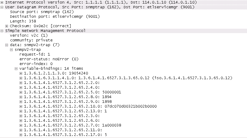
In case of SNMP logging to a remote node, set the log destination to the SNMP destination. Allocation or de-allocation of each port block triggers sending a SNMP trap message to the trap destination.
Configure SNMP trap logging (MD-CLI)
[ex:/configure log]
A:admin@node-2# info
...
    filter "1" {
        default-action drop
        named-entry "1" {
            action forward
            match {
                application {
                    eq nat
                }
                event {
                    eq 2012
                }
            }
        }
    }
    log-id "6" {
        filter "1"
        source {
            main true
        }
        destination {
            snmp {
            }
        }
    }
    snmp-trap-group "6" {
        trap-target "nat" {
            address 192.168.1.10
            port 9001
            version snmpv2c
            notify-community "private"
        }
    }
Configure SNMP trap logging (classic CLI)
A:node-2>config>log# info
----------------------------------------------
       filter 1
            default-action drop
            entry 1
                action forward
                match
                    application eq "nat"
                    number eq 2012
                exit
            exit
        exit

        snmp-trap-group 6
            trap-target "nat" address 192.168.1.10 port 9001 snmpv2c notify-community "private"
        exit
        log-id 6
            filter 1
            from main
            to snmp
        exit
The following figure shows an SNMP trap message.
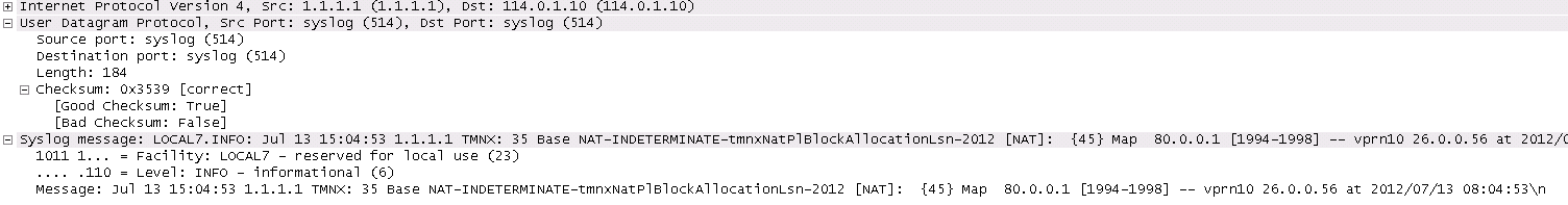
NAT syslog
The follow example displays NAT logs configured to be sent to a syslog remote facility. A separate syslog message is generated for every port-block allocation or de-allocation.
Configure the sending of NAT logs to a syslog remote facility (MD-CLI)
[ex:/configure log]
A:admin@node-2# info
...
    filter "1" {
        default-action drop
        named-entry "1" {
            action forward
            match {
                application {
                    eq nat
                }
                event {
                    eq 2012
                }
            }
        }
    }
    log-id "7" {
        filter "1"
        source {
            main true
        }
        destination {
            syslog "7"
        }
    }
    syslog "7" {
        address 192.168.1.10
    }
Configure the sending of NAT logs to a syslog remote facility (classic CLI)
A:node-2>config>log# info
----------------------------------------------
...
        filter 1
            default-action drop
            entry 1 name "1"
                action forward
                match
                    application eq "nat"
                    number eq 2012
                exit
            exit
        exit
        syslog 7
            address 192.168.1.10
        exit


         log-id 7 name "7"
            filter 1
            from main
            to syslog 7
            no shutdown
        exit
----------------------------------------------
The following figure displays a syslog message.
- cleared
- indeterminate
- critical
- major
- minor
- warning
Change the event severity level (MD-CLI)
*[ex:/configure]
A:admin@node-2# log log-events nat event * severity major
Change the event severity level (classic CLI)
*A:node-2# configure log event-control "nat" 2012 generate majorSummarization logs and bulk operations
Bulk operations, such as removing a NAT policy or shutting down a NAT pool, can trigger a cascade of events, such as release of NAT subscribers associated with the NAT policy or a NAT pool. To avoid excessive logging during those operations, summarization logs are used. These logs carry relational information that connects multiple events and are categorized under event log 99 on the CPM. Configurable destinations for these logs include SNMP notification (trap), syslog (sent in syslog format to the syslog collector), memory (sent to memory buffer), local file, and NETCONF.
Tracking NAT subscribers based on the logs becomes more complicated if they were terminated because of bulk operations. A MAP log is generated when NAT resources for the NAT subscriber are allocated; a FREE log is generated when NAT resources for the NAT subscriber are released. Typically, individual MAP logs are paired with corresponding FREE logs to determine the identity and activity duration for the NAT subscriber. However, during bulk operations, individual FREE logs are substituted with a summarized log containing relational information. In such cases, identifying NAT subscriber mappings may necessitate examining multiple logging sources, such as a combination of RADIUS and summarization logs.
To simplify log summarization, a policy ID is added as a connecting option in all logs. The policy ID follows the format: plcy-id XX
Where: XX is a unique number representing a NAT policy and assigned by the router for each inside routing context, as shown in the following example.
670 2023/05/31 12:55:00.952 UTC MINOR: NAT #2012 vprn601 NAT
"{986} Map  10.10.10.1 [4001-4279] MDA 5/1 -- 1166016512 classic-lsn-sub
%203 vprn101 192.0.2.1 at 2023/05/31 12:55:00"
When an active NAT policy is removed from the configuration within an inside routing context, all NAT subscribers associated with that NAT policy in that context are removed from the system. Instead of generating individual FREE logs for each subscriber, a single summarized log is generated. This summarized log entry contains only the policy ID of the removed NAT policy and the inside service ID. To determine which NAT resources were released, the user must match the policy ID and the service ID in the summarization log with those in all MAP logs that lack a pairing explicit FREE log.
A summarization log is always created on the CPM, regardless of whether RADIUS logging is enabled.
A summarization log is generated on the CPM under the following circumstances:
-
NAT policy removal
If there is a single NAT policy for each inside routing context, the summarization log contains the inside service ID (VPRN or Base). To identify the terminated NAT mappings for subscribers, search all individual MAP logs matching the service ID from the summarization log.
When there are multiple NAT policies per inside routing context, the summarization log contains the inside service ID and policy ID. Search individual logs based on policy ID and inside service ID to identify subscribers affected by the NAT policy removal.
-
pool administratively disabled
The router sends a summarization log with the outside service ID and all IP address ranges in the pool. Match individual logs based on outside IP address and outside service ID to identify released NAT subscribers.
-
IP address range removal from the pool
The summarization log includes the outside service ID and the removed IP address range. Match individual logs based on the outside IP addresses in the range and the outside service ID to identify the released NAT subscribers.
-
Non deterministic source prefix removal
The summarization log includes the removed source prefix, policy ID, and inside service ID.
-
Last AFTR address removal
The summarization log includes the inside service ID.
Summarization logs are enabled by event controls 2021 (tmnxNatLsnSubBlksFree), 2016 (tmnxNatPlAddrFree), and 2030 (tmnxNatInAddrPrefixBlksFree). These events are suppressed by default. Event control 2021 also reports when all port blocks for a NAT subscriber are freed.
Histogram
The distribution of the following resources in a NAT pool is tracked in the form of a histogram:
-
Ports and NAT subscribers
The distribution of outside ports in a NAT pool is tracked for an aggregate number of NAT subscribers. The output of the following command can reveal the number of NAT subscribers in a pool that are heavy port users, or it can reveal the average number of ports used by most NAT subscribers.
show router nat pool histogram -
Port blocks and NAT subscribers in a NAT pool
The distribution of port blocks is tracked for an aggregate number of NAT subscribers. The output of the histogram command can reveal how NAT subscribers are using port blocks in the aggregate.
-
NAT subscribers and IP addresses
The distribution of NAT subscribers across IP addresses is tracked. The output of the histogram command is used to determine if any substantial imbalances exist.
-
Extended port blocks and outside IP addresses in a NAT pool
The distribution of extended port blocks in the NAT pool is tracked in relation to an aggregate number of outside IP addresses. The output of the histogram command can reveal how extended port blocks are distributed over IP addresses in an aggregate.
The user can use the displayed information to adjust the port block size per NAT subscriber, the amount of port blocks per NAT subscriber, or see port usage trends over time. Consequently, the user can adjust the configuration as the port demand per NAT subscriber increases or decreases over time. For example, a user may find that the port usage in a pool increased over a period of time. Accordingly, the user can plan to increase the number of ports per port block.
Execute the following show commands to display the histogram output.
Ports and NAT subscribers per NAT pool
Use the following command to show ports and subscribers per NAT pool . The output is organized in port buckets with the number of NAT subscribers in each bucket.
show router nat pool "pool-1" histogram ports bucket-size 200 num-buckets 10Ports and NAT subscribers per NAT pool output
===============================================================================
Usage histogram NAT pool "pool-1" router "Base"
===============================================================================
Num-ports   Sub-TCP    Sub-UDP    Sub-ICMP
-------------------------------------------------------------------------------
1-199       17170      0          0
200-399     8707       0          0
400-599     2406       0          0
600-799     635        0          0
800-999     322        0          0
1000-1199   0          0          0
1200-1399   0          0          0
1400-1599   0          0          0
1600-1799   0          0          0
1800-       0          0          0
-------------------------------------------------------------------------------
No. of entries: 10
===============================================================================
Port blocks and NAT subscribers per NAT pool
Use the following command to show ports and NAT subscribers per NAT pool. The output is organized by the increasing number of port blocks in a NAT pool with the number of NAT subscribers using the number of port blocks indicated in each line.
show router nat pool "l2a" histogram port-blocksPort blocks and NAT subscribers per NAT pool output
===============================================================================
Usage histogram NAT pool "l2a" router "Base" port blocks per subscriber
===============================================================================
Num port-blocks      Num subscribers
-------------------------------------------------------------------------------
1                    17398
2                    8550
3                    2352
4                    940
5                    0
6                    0
7                    0
8                    0
9                    0
10                   0
-------------------------------------------------------------------------------
No. of entries: 10
===============================================================================
NAT subscribers and IP addresses per NAT pool (LSN)
Use the following command to show NAT subscribers and IP addresses per NAT pool (LSN). The output is organized in buckets where each bucket shows how the NAT subscribers are spread over the preferred outside IP addresses. For example, the output of the below command shows that each of the 513 IP addresses in the pool have 120 to 129 NAT subscribers. This is a fairly even distribution of NAT subscribers over IP addresses and the favorable output of this command.
show router 5 nat pool "demo" histogram subscribers-per-ip bucket-size 10 num-buckets 50NAT subscribers and IP addresses per NAT pool (LSN) output
===============================================================================
Usage histogram NAT pool "demo" router 5 subscribers per IP address
===============================================================================
Num subscribers     Num IP addresses
-------------------------------------------------------------------------------
1-9                 0
10-19               0
20-29               0
30-39               0
40-49               0
50-59               0
60-69               0
70-79               0
80-89               0
90-99               0
100-109             0
110-119             0
120-129             513
130-139             0
140-149             0
150-159             0
160-169             0
170-179             0
180-189             0
190-199             0
200-209             0
210-219             0
220-229             0
230-239             0
240-249             0
250-259             0
260-269             0
270-279             0
280-289             0
290-299             0
300-309             0
310-319             0
320-329             0
330-339             0
340-349             0
350-359             0
360-369             0
370-379             0
380-389             0
390-399             0
400-409             0
410-419             0
420-429             0
430-439             0
440-449             0
450-459             0
460-469             0
470-479             0
480-489             0
490-                0
Extended port blocks in a NAT pool and outside IP addresses
Use the following command to show NAT subscribers and IP addresses per NAT pool (LSN). The output is organized in extended port-block buckets in a NAT pool with the number of outside IP addresses in each bucket.
show router nat pool "l2a" histogram extended-port-blocks-per-ip bucket-size 1 num-buckets 10Extended port blocks in a NAT pool and outside IP addresses output
===============================================================================
Usage histogram NAT pool "l2a" router "Base" extended port blocks per IP address
===============================================================================
Num extended-port-blocks      Num IP addresses
-------------------------------------------------------------------------------
-                             -
1-1                           1039
2-2                           6182
3-3                           777
4-4                           194
5-5                           0
6-6                           0
7-7                           0
8-8                           0
9-                            0
-------------------------------------------------------------------------------
No. of entries: 10
===============================================================================
The output of each command can be periodically exported to an external destination with the cron command.
The following example displays the script, script policy, and CRON configuration
Configure the script, script policy, and CRON (MD-CLI)
[ex:/configure system]
A:admin@node-2# info
...
    cron {
        schedule "nat_histogram_schedule" owner "TiMOSCLI" {
            admin-state enable
            interval 600
            script-policy {
                name "dump_nat_histogram"
            }
        }
    }
...
    script-control {
        script "nat_histogram" owner "TiMOSCLI" {
            admin-state enable
            location "ftp://*:*@138.203.8.62/nat-histogram.txt"
        }
        script-policy "dump_nat_histogram" owner "TiMOSCLI" {
            admin-state enable
            results "ftp://*:*@138.203.8.62/nat_histogram_results.txt"
            script {
                name "nat_histogram"
            }
        }
    }
Configure the script, script policy, and CRON (classic CLI)
A:node-2>config>system# info
----------------------------------------------
#--------------------------------------------------
echo "System Configuration"
#--------------------------------------------------
...
        script-control
            script "nat_histogram" owner "TiMOSCLI"
                no shutdown
                location "ftp://*:*@138.203.8.62/nat-histogram.text"
            exit
            script-policy "dump_nat_histogram" owner "TiMOSCLI"
                no shutdown
                results "ftp://*:*@130.203.8.62/nat_histogram_results.text"
                script "nat_histogram"
            exit
        exit
        cron
            schedule "nat_histogram_schedule" owner "TiMOSCLI"
                interval 600
                script-policy "dump_nat_histogram"
                no shutdown
            exit
        exit
#--------------------------------------------------
The nat-histogram.txt file contains the command execution line.
show router nat pool "pool-1" histogram ports bucket-size 200 num-buckets 10This command is executed every 10 minutes (600 seconds) and the output of the command is written into a set of files on an external TFP server as displayed in the following example.
Files on an external TFP server
[root@ftp]# ls nat_histogram_results.txt*
    nat_histogram_results.txt_20130117-153548.out
    nat_histogram_results.txt_20130117-153648.out
    nat_histogram_results.txt_20130117-153748.out
    nat_histogram_results.txt_20130117-153848.out
    nat_histogram_results.txt_20130117-153948.out
    nat_histogram_results.txt_20130117-154048.out
    [root@ftp]#
Configuring NAT
This section provides information to configure NAT using the command line interface.
Large scale NAT configuration
The following example displays a Large Scale NAT configuration.
MD-CLI
[ex:/configure]
A:admin@node-2# admin show configuration
configure {
...
    card 3 {
        card-type imm-2pac-fp3
        mda 1 {
            mda-type isa2-bb
        }
        mda 2 {
            mda-type isa2-bb
        }
    }
    filter {
        ip-filter "123" {
            entry 10 {
                match {
                    src-ip {
                        address 10.0.0.1/8
                    }
                }
                action {
                    nat {
                    }
                }
            }
        }
    }
    isa {
        nat-group 1 {
            admin-state enable
            redundancy {
                active-mda-limit 2
            }
            mda 3/1 { }
            mda 3/2 { }
        }
    }
    service {
        nat {
            nat-policy "ls-outPolicy" {
                pool {
                    router-instance "500"
                    name "nat1-pool"
                }
                timeouts {
                    udp {
                        normal 18000
                        initial 240
                    }
                }
            }
        }
        vprn "500" {
            admin-state enable
            customer "1"
            router-id 10.21.1.2
            nat {
                outside {
                    pool "nat1-pool" {
                        admin-state enable
                        type large-scale
                        nat-group 1
                        port-reservation {
                            ports 200
                        }
                        address-range 10.81.0.0 end 10.81.6.0 {
                        }
                    }
                }
            }
            bgp-ipvpn {
                mpls {
                    admin-state enable
                    route-distinguisher "500:10"
                    vrf-target {
                        import-community "target:500:1"
                        export-community "target:500:1"
                    }
                }
            }
            interface "ip-192.168.113.1" {
                ipv4 {
                    primary {
                        address 192.168.113.1
                        prefix-length 24
                    }
                    neighbor-discovery {
                        static-neighbor 192.168.113.5 {
                            mac-address 00:00:5e:00:53:00
                        }
                    }
                }
                sap 1/1/1:200 {
                }
            }
        }
        vprn "550" {
            customer "1"
            router-id 10.21.1.2
             nat {
                inside {
                    large-scale {
                        nat-policy "ls-outPolicy"
                    }
                }
            }
            bgp-ipvpn {
                mpls {
                    admin-state enable
                    route-distinguisher "550:10"
                    vrf-target {
                        import-community "target:550:1"
                        export-community "target:550:1"
                    }
                }
            }
            interface "ip-192.168.13.1" {
                ipv4 {
                    primary {
                        address 192.168.13.1
                        prefix-length 8
                    }
                }
                sap 1/2/1:900 {
                    ingress {
                        filter {
                            ip "123"
                        }
                    }
                }
            }
        }
    }
...
classic CLI
A:node-2# admin display-config
configure
#--------------------------------------------------
echo "Card Configuration"
#--------------------------------------------------
    card 3
        card-type imm-2pac-fp3
        mda 1
            mda-type isa2-bb
        exit
        mda 2
            mda-type isa2-bb
        exit
    exit
#--------------------------------------------------
echo "ISA Configuration"
#--------------------------------------------------
    isa
        nat-group 1 create
            active-mda-limit 2
            mda 3/1
            mda 3/2
            no shutdown
        exit
    exit
#--------------------------------------------------
echo "Filter Configuration"
#--------------------------------------------------
    filter
        ip-filter 123 create
            entry 10 create
                match
                    src-ip 10.0.0.1/8
                exit
                action nat
            exit
        exit
    exit
#--------------------------------------------------
echo "NAT (Declarations) Configuration"
#--------------------------------------------------
    service
        nat
            nat-policy "ls-outPolicy" create
            exit
        exit
    exit
#--------------------------------------------------
echo "Service Configuration"
#--------------------------------------------------
    service
        customer 1 create
            description "Default customer"
        exit
        vprn 500 customer 1 create
            interface "ip-192.168.113.1" create
            exit
            nat
                outside
                    pool "nat1-pool" nat-group 1 type large-scale create
                        port-reservation ports 200
                        address-range 10.81.0.0 10.81.6.0 create
                        exit
                        no shutdown
                    exit
                exit
            exit
        exit
        vprn 550 customer 1 create
            interface "ip-192.168.13.1" create
            exit
        exit
        nat
            nat-policy "ls-outPolicy" create
                pool "nat1-pool" router 500
                timeouts
                    udp hrs 5
                    udp-initial min 4
                exit
            exit
        exit
        vprn 500 customer 1 create
            router-id 10.21.1.2
            route-distinguisher 500:10
            vrf-target export target:500:1 import target:500:1
            interface "ip-192.168.113.1" create
                address 192.168.113.1/24
                static-arp 192.168.113.5 00-00-5e-00-53-00
                sap 1/1/1:200 create
                exit
            exit
            no shutdown
        exit
        vprn 550 customer 1 create
            router-id 10.21.1.2
            route-distinguisher 550:10
            vrf-target export target:550:1 import target:550:1
            interface "ip-192.168.13.1" create
                address 192.168.13.1/8
                sap 1/2/1:900 create
                    ingress
                        filter ip 123
                    exit
                exit
            exit
            nat
                inside
                    nat-policy "ls-outPolicy"
                exit
            exit
            no shutdown
        exit
    exit
exit all
NAT configuration examples
The following examples display configuration information for a VPRN service, router NAT, and a NAT service.
Configure the VPRN service (MD-CLI)
[ex:/configure service vprn "100" nat]
A:admin@node-2# info
    inside {
        l2-aware {
            force-unique-ip-addresses false
        }
        large-scale {
            nat-policy "priv-nat-policy"
            traffic-identification {
                source-prefix-only false
            }
            nat44 {
                destination-prefix 0.0.0.0/0 {
                }
            }
            dual-stack-lite {
                admin-state enable
                subscriber-prefix-length 128
                endpoint 2001:db8:470:fff:190:1:1:1 {
                    tunnel-mtu 1500
                    reassembly false
                    min-first-fragment-size-rx 1280
                }
                endpoint 2001:db8:470:1f00:ffff:190:1:1 {
                    tunnel-mtu 1500
                    reassembly false
                    min-first-fragment-size-rx 1280
                }
            }
            subscriber-identification {
                admin-state disable
                drop-unidentified-traffic false
                attribute {
                    vendor nokia
                    type alc-sub-string
                }
            }
        }
    }
Configure the VPRN service (classic CLI)
A:node-2>config>service# info detail
----------------------------------------------
        vprn 100 name "100" customer 1 create
            shutdown
            nat
                inside
                    nat-policy "priv-nat-policy"
                    destination-prefix 0.0.0.0/0
                    dual-stack-lite
                        subscriber-prefix-length 128
                        address 2001:db8:470:1f00:ffff:190:1:1
                            tunnel-mtu 1500
                        exit
                        no shutdown
                    exit
                    redundancy
                        no peer
                        no steering-route
                    exit
                    subscriber-identification
                        shutdown
                        no attribute
                        no description
                        no radius-proxy-server
                    exit
                    l2-aware
                    exit
                exit
                outside
                    no mtu
                exit
Configure a router NAT (MD-CLI)
[ex:/configure router "Base" nat outside]
A:admin@node-2# info
    pool "privpool" {
        admin-state enable
        type large-scale
        nat-group 3
        address-pooling paired
        icmp-echo-reply false
        mode auto
        applications {
            agnostic false
            flexible-port-allocation false
        }
        port-forwarding {
            dynamic-block-reservation false
            range-start 1
            range-end 1023
        }
        port-reservation {
            port-blocks 128
        }
        large-scale {
            subscriber-limit 65535
            redundancy {
                admin-state disable
            }
        }
        address-range 10.0.0.5 end 10.0.0.6 {
            drain false
        }
    }
    pool "pubpool" {
        admin-state enable
        type large-scale
        nat-group 1
        address-pooling paired
        icmp-echo-reply false
        mode auto
        applications {
            agnostic false
            flexible-port-allocation false
        }
        port-forwarding {
            dynamic-block-reservation false
            range-start 1
            range-end 1023
        }
        port-reservation {
            port-blocks 1
        }
        large-scale {
            subscriber-limit 65535
            redundancy {
                admin-state disable
            }
        }
        address-range 192.168.8.241 end 192.168.8.247 {
            drain false
        }
    }
    pool "test" {
        type large-scale
        nat-group 1
    }
Configure a router NAT (classic CLI)
A:node-2>config>router>nat# info detail
----------------------------------------------
            outside
                no mtu
                pool "privpool" nat-group 3 type large-scale create
                    no description
                    port-reservation blocks 128
                    port-forwarding-range 1023
                    redundancy
                        no export
                        no monitor
                    exit
                    subscriber-limit 65535
                    no watermarks
                    mode auto
                    address-range 10.0.0.5 10.0.0.6 create
                        no description
                        no drain
                    exit
                    no shutdown
                exit
                pool "pubpool" nat-group 1 type large-scale create
                    no description
                    port-reservation blocks 1
                    port-forwarding-range 1023
                    redundancy
                        no export
                        no monitor
                    exit
                    subscriber-limit 65535
                    no watermarks
                    mode auto
                    address-range 192.168.8.241 192.168.8.247 create
                        no description
                        no drain
                    exit
                    no shutdown
                exit
            exit
Configure a service NAT (MD-CLI)
[ex:/configure service nat nat-policy "priv-nat-policy"]
A:admin@node-2# info
    block-limit 4
    filtering endpoint-independent
    port-forwarding-range-end 1023
    pool {
        router-instance "Base"
        name "privpool"
    }
    alg {
        ftp true
        pptp false
        rtsp true
        sip true
    }
    port-limits {
        forwarding 64
        dynamic-ports 65536
    }
    priority-sessions {
        fc {
            be false
            l2 false
            af false
            l1 false
            h2 false
            ef false
            h1 false
            nc false
        }
    }
    session-limits {
        max 65535
    }
    tcp {
        reset-unknown false
    }
    timeouts {
        icmp-query 60
        sip 120
        subscriber-retention 0
        tcp {
            established 7440
            rst 0
            syn 15
            time-wait 0
            transitory 240
        }
        udp {
            normal 300
            dns 15
            initial 15
        }
    }
    udp {
        inbound-refresh false
    }

[ex:/configure service nat nat-policy "pub-nat-policy"]
A:admin@node-2# info
    block-limit 1
    filtering endpoint-independent
    port-forwarding-range-end 1023
    pool {
        router-instance "Base"
        name "pubpool"
    }
    alg {
        ftp true
        pptp false
        rtsp false
        sip false
    }
    port-limits {
        dynamic-ports 65536
    }
    priority-sessions {
        fc {
            be false
            l2 false
            af false
            l1 false
            h2 false
            ef false
            h1 false
            nc false
        }
    }
    session-limits {
        max 65535
    }
    tcp {
        reset-unknown false
    }
    timeouts {
        icmp-query 60
        sip 120
        subscriber-retention 0
        tcp {
            established 7440
            rst 0
            syn 15
            time-wait 0
            transitory 240
        }
        udp {
            normal 300
            dns 15
            initial 15
        }
    }
    udp {
        inbound-refresh false
    }
Configure a service NAT (classic CLI)
A:node-2>config>service>nat# info detail
----------------------------------------------
            nat-policy "priv-nat-policy" create
                alg
                    ftp
                    rtsp
                    sip
                exit
                block-limit 4
                no destination-nat
                no description
                filtering endpoint-independent
                pool "privpool" router Base
                no ipfix-export-policy
                port-limits
                    forwarding 64
                    no reserved
                    no watermarks
                exit
                priority-sessions
                exit
                session-limits
                    max 65535
                    no reserved
                    no watermarks
                exit
                timeouts
                    icmp-query min 1
                    sip min 2
                    no subscriber-retention
                    tcp-established hrs 2 min 4
                    tcp-syn sec 15
                    no tcp-time-wait
                    tcp-transitory min 4
                    udp min 5
                    udp-initial sec 15
                    udp-dns sec 15
                exit
                no tcp-mss-adjust
                no udp-inbound-refresh
            exit
            nat-policy "pub-nat-policy" create
                alg
                    ftp
                    no rtsp
                    no sip
                exit
                block-limit 1
                no destination-nat
                no description
                filtering endpoint-independent
                pool "pubpool" router Base
                no ipfix-export-policy
                port-limits
                    no forwarding
                    no reserved
                    no watermarks
                exit
                priority-sessions
                exit
                session-limits
                    max 65535
                    no reserved
                    no watermarks
                exit
                timeouts
                    icmp-query min 1
                    sip min 2
                    no subscriber-retention
                    tcp-established hrs 2 min 4
                    tcp-syn sec 15
                    no tcp-time-wait
                    tcp-transitory min 4
                    udp min 5
                    udp-initial sec 15
                    udp-dns sec 15
                exit
                no tcp-mss-adjust
                no udp-inbound-refresh
            exit
Expanding a NAT group
Adding or removing an MDA from a NAT group affects all currently active subscribers and may invalidate existing static port forwards and mappings configured in deterministic NAT.
Store configurations offline before removing the configuration as part of the NAT group modification process that is described in the following information. You can restore the configuration to the node after the change is complete.
The procedure to add or remove an MDA from a NAT group is described in the following information.
Adding and removing an MDA from a NAT group in the MD-CLI
-
Administratively disable deterministic prefix policies and delete their mappings. Perform this for every deterministic prefix and their mapping used in a NAT group in which the size is modified. Store the deterministic mapping configuration offline before removing it and then reapply after the change. When the NAT group size is modified and the deterministic mappings reapplied, the commit may fail. If the commit fails, you must create a new mapping. Use the following command to create a new mapping.
tools perform nat deterministic calculate-mapsStatic port forwards configurations created with the tools command are automatically deleted during the commitment of the modified NAT group.
-
Commit the changes.
-
Change the active and failed MDA limit.
-
Commit the changes.
-
Re-apply deterministic mappings and static port forwards.
Adding and removing an MDA from a NAT group in the classic CLI
In the classic CLI, use the following steps to add or remove an MDA from a NAT group:
-
Shut down the NAT group.
-
Remove all statically configured large-scale subscribers (such as deterministic, LI, debug, and subscriber aware) in a NAT group that is being modified.
-
A static port forward configuration created via the tools command is automatically deleted.
-
Manually delete any static port forward configurations that were created..
-
Shut down and remove the deterministic policies.
-
Delete NAT policy references in all inside routing contexts associated with the NAT group that is being modified.
-
Reconfigure the active-mda-limit and failed-mda-limit options.
-
Administratively enable the NAT group.
-
Restore previously removed NAT group references in all of the inside routing contexts associated with the modified NAT group.
-
Reapply the subscriber-aware and deterministic subscribers (prefixes and maps), static port forwards, LI, and debug.