Ports
Port types
Before a port can be configured, the slot must be provisioned with a card type and MDA type.
7705 SAR Gen 2 routers support the following port types:
-
Ethernet
Supported Ethernet port types include:
-
Fast Ethernet (10/100BASE-T)
-
Gb Ethernet (1GbE, 1000BASE-T)
-
10 Gb Ethernet (10GbE, 10GBASE-X)
-
25 Gb Ethernet (25GBASE-R)
Router ports must be configured as either access, network, or hybrid. The default is network.
-
-
access
Access ports are configured with services to carry customer-facing traffic. If a Service Access Port (SAP) is required on a port or channel, it must first be configured as an access port or channel. When a port is configured for access mode, the appropriate encapsulation type must be configured to distinguish the services on the port or channel. After a port has been configured for access mode, one or more services can be configured on the port or channel, depending on the encapsulation value.
-
network
Network ports are configured for network-facing traffic. These ports participate in the service provider transport or infrastructure network. Dot1q is supported on network ports.
-
hybrid
Hybrid ports are configured for access and network-facing traffic. While the default mode of an Ethernet port remains network, the port cannot change between access, network, and hybrid modes unless the port is first shut down and any configured SAPs or interfaces are deleted.
Hybrid ports can operate in both access and network modes. The MTU of a port in hybrid mode is the same as in network mode. The default encapsulation for hybrid port mode is dot1q; the port also supports QinQ encapsulation. Null hybrid port mode is not supported. After the port is changed to hybrid, the default MTU is changed to 9212 bytes, the value currently used in network mode (higher than an access port). This ensures that both SAP and network VLANs are accommodated. The only exception applies to 10/100 Fast Ethernet ports operating in hybrid mode. In those cases, this set to 1522 bytes, which corresponds to the default access MTU with QinQ, which is larger than the network dot1q MTU or access dot1q MTU for this type of Ethernet port.
All command options in the access and network contexts can be configured within the port using the same CLI hierarchy as in the existing implementation. The difference is that a port configured in hybrid mode allows both ingress and egress contexts to be configured concurrently.
An Ethernet port configured in hybrid mode can have two encapsulation types: dot1q and QinQ. The NULL value is not supported because a single SAP is allowed, and can be achieved by configuring the port in the access mode, or a single network IP interface is allowed, which can be achieved by configuring the port in network mode.
Hybrid mode can be enabled on a LAG port when the port is part of a single-chassis LAG configuration. When the port is part of a multichassis LAG configuration, it can only be configured to access mode because MC-LAG is not supported on network ports and, consequently, is not supported on hybrid ports. The same restriction applies to a port that is part of an MC-Ring configuration.
For a hybrid port, use the following commands to split the amount of allocated port buffers for ingress and egress equally between network and access contexts:
-
MD-CLI
configure port hybrid-buffer-allocation ingress-weight access network configure port hybrid-buffer-allocation egress-weight access network -
classic CLI
configure port hybrid-buffer-allocation ing-weight access network
configure port hybrid-buffer-allocation egr-weight access network
Adapting the terminology in buffer-pools, the access active bandwidth and network active bandwidth of the port are derived in each ingress and egress as follows (egress formulas shown only):
-
total-hybrid-port-egress-weights = access-weight + network-weight
-
hybrid-port-access-egress-factor = access-weight / total-hybrid-port-egress-weights
-
hybrid-port-network-egress-factor = network-weight / total-hybrid-port-egress-weights
-
port-access-active-egress-bandwidth = port-active-egress-bandwidth x hybrid-port-access-egress-factor
-
port-network-active-egress-bandwidth = port-active-egress-bandwidth x hybrid-port-network-egress-factor
-
-
GNSS receiver
The 7705 SAR-Hx and 7705 SAR-Mx are equipped with an integrated Global Navigation Satellite System (GNSS) receiver and GNSS radio frequency (RF) port for retrieval and recovery of GPS and Galileo signals.
Note: Signal recovery must always be enabled in the system configuration when the GNSS receiver is used.See the 7705 SAR Gen 2 Basic System Configuration Guide for information about using a GNSS receiver as a timing source for the node.
-
WAN PHY
Note: WAN mode is not supported on the 7705 SAR Gen 2.10 G Ethernet ports can be configured in WAN PHY mode. Use commands in the following context to configure 10 G Ethernet ports in WAN PHY mode.
configure port ethernet xgigWhen configuring the port in WAN mode, you can change specific SONET/SDH command options to reflect the SONET/SDH requirements for this port.
-
TDM
Time-Division Multiplexing (TDM) ports support access mode only. Supported TDM port types on the 7705 SAR-Hx and 7705 SAR-Mx include:
-
E1
-
RS232
-
C37.94
-
-
LAG
A Link Aggregation Group (LAG) can be used to group multiple ports into one logical link. The aggregation of multiple physical links allows for load sharing and offers seamless redundancy. If one of the links fails, traffic is redistributed over the remaining links.
-
connector
A connector that can accept transceiver modules including breakout connectors to multiple physical ports. For example, an SFP28 connector can support 1Gb, 10 Gb, and 25 Gb Ethernet ports, depending on the port speed mode configuration. The connectors themselves cannot be used as ports in other commands, however, the breakout ports can be used as any Ethernet port.
See Ethernet ports for more information.
Ethernet ports
This section provides information about the supported Ethernet ports and pluggable transceiver types for 7705 SAR Gen 2 platforms.
The following table lists the supported speeds for pluggable transceiver types. See Port speed modes for more information.
| Pluggable transceiver type | Supported speeds |
|---|---|
| SFP |
SFP transceivers support speeds of 1 Gb/s, unless 100 Mb/s support is noted in other table footnotes. |
| SFP+ | SFP+ transceivers support speeds of 10 Gb/s. |
| SFP28 | SFP28 transceivers support speeds of 25 Gb/s. |
The following table lists the supported port types and pluggable transceivers for 7705 SAR Gen 2 platforms.
| 7705 SAR Gen 2 hardware |
Physical port type |
Accepted pluggable transceivers | ||
|---|---|---|---|---|
| SFP | SFP+ | SFP28 | ||
| 7705 SAR-1 | ||||
| m10-sfp++6-sfp | SFP | ✓ | ||
| SFP+ | ✓ | ✓ | ||
| 7705 SAR-Hx and 7705 SAR-Mx | ||||
| m4-1g-rj+6-10g-sfp++2-25g-sfp28 | SFP+ | ✓ | ✓ | |
| SFP28 | ✓ | ✓ | ✓ | |
| RJ45 | ||||
| m2-1g-sfp+2-10g-sfp+ | SFP | ✓ | ||
| SFP+ | ✓ | ✓ | ||
Port speed modes
- MD-CLI
admin system port-speed-mode mode - classic
CLI
admin system port-speed-mode
The following table lists the supported port speeds in each speed mode.
| Speed mode | Port and port type | |||||||||||||||
|---|---|---|---|---|---|---|---|---|---|---|---|---|---|---|---|---|
| MDA-c1 | MDA-c2 | MDA-c3 | MDA-c4 | 1 | 2 | 3 | 4 | c5 | c6 | c7 | c8 | c9 | c10 | c11 | c12 | |
| SFP | SFP+ | RJ45 | SFP+ | SFP+ or SFP28 | ||||||||||||
|
Speed mode 1 1G/10G |
1G | 1G | 1G/10G | 1G/10G | 10/100/1000 | 10/100/1000 | 10/100/1000 | 10/100/1000 | 1G/10G | 1G/10G | 1G/10G | 1G/10G | 1G/10G | 1G/10G | 1G/10G | 1G/10G |
|
Speed mode 2 10G/25G |
1G | 1G | 1G/10G | 1G/10G | 10/100/1000 | 10/100/1000 | 10/100/1000 | 10/100/1000 | 10G | 10G | 10G | 10G | 10G | 10G | 10G/25G | 10G/25G |
TDM
TDM ports are supported on the following MDAs:
8-port T1/E1 ASAP Adapter card
T1/E1 port configuration is available on the 8-port T1/E1 ASAP Adapter card supported on the 7705 SAR-Hx and 7705 SAR-Mx.
On T1/E1 ports, channelization is supported down to the DS0 level. To change port types, all ports must first be administratively disabled. The ports can be configured for E1 operation. When the first port on a card is configured, all other ports on the card must be set to the same type.
T1/E1 ports support only cem encapsulation.
8-port RS-232 and C37.94 combination MDA
This MDA is supported on the 7705 SAR-Hx and 7705 SAR-Mx.
On the 8-port RS-232 and C37.94 combination MDA, channelization is supported down to the DS0 level on the four RS-232 serial ports and four IEEE C37.94 teleprotection interface (TPIF) ports.
The RS-232 and C37.94 ports are used in critical networks for applications like SCADA and teleprotection.
Port features
Port State and Operational State
There are two port attributes that are related and similar but have slightly different meanings: Port State and Operational State (or Operational Status).
The following descriptions are based on normal individual ports. Many of the same concepts apply to other objects that are modeled as ports in the router such as APS groups but the show output descriptions for these objects should be consulted for the details.
-
Port State
-
Displayed in port summaries such as show port or show port 1/1
-
tmnxPortState in the TIMETRA-PORT-MIB
-
Values: None, Ghost, Down (linkDown), Link Up, Up
-
-
Operational State
-
Displayed in the show output of a specific port such as show port 2/1/3
-
tmnxPortOperStatus in the TIMETRA-PORT-MIB
-
Values: Up (inService), Down (outOfService)
-
The behavior of Port State and Operational State are different for a port with link protocols configured (for example, LACP for Ethernet ports). A port with link protocols configured only transitions to the Up Port State when the physical link is up and all the configured protocols are up. A port with no link protocols configured transitions from Down to Link Up and then to Up immediately after the physical link layer is up.
The linkDown and linkUp log events (events 2004 and 2005 in the SNMP application group) are associated with transitions of the port Operational State. Note that these events map to the RFC 2863, The Interfaces Group MIB, (which obsoletes RFC 2233, The Interfaces Group MIB using SMIv2) linkDown and linkUp traps as mentioned in the SNMPv2-MIB.
An Operational State of Up indicates that the port is ready to transmit service traffic (the port is physically up and any configured link protocols are up). The relationship between port Operational State and Port State is shown in Relationship of Port state and Oper state.
|
Port state |
Operational state (Oper state or Oper status) (as displayed in ‟show port x/y/z”) | |
|---|---|---|
|
Port State (as displayed in the show port summary) |
For ports that have no link layer protocols configured |
For ports that have link layer protocols configured (PPP, LACP, 802.3ah EFM, 802.1ag Eth-CFM) |
|
Up |
Up |
Up |
|
Link Up (indicates the physical link is ready) |
Up |
Down |
|
Down |
Down |
Down |
802.1x network access control
Nokia routers support network access control of client devices (PCs, STBs, and so on) on an Ethernet network using the IEEE. 802.1x standard. 802.1x is known as Extensible Authentication Protocol (EAP) over a LAN network or EAPOL.
802.1x basics
The IEEE 802.1x standard defines three participants in an authentication conversation (see 802.1x architecture that shows an example with the 7705 SAR Gen 2).
- the supplicant
- the end-user device that requests access to the network
- the authenticator
- controls access to the network. Both the supplicant and the authenticator are referred to as Port Authentication Entities (PAEs).
- the authentication server
- performs the actual processing of the user information
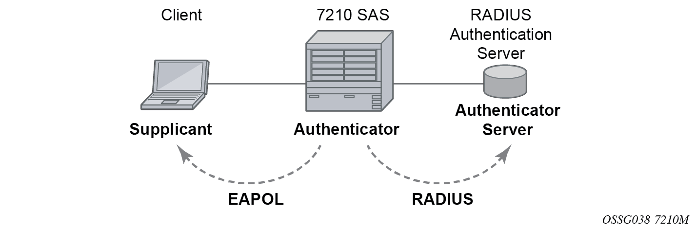
The authentication exchange is carried out between the supplicant and the authentication server, the authenticator acts only as a bridge. The communication between the supplicant and the authenticator is done through the Extended Authentication Protocol (EAP) over LANs (EAPOL). On the back end, the communication between the authenticator and the authentication server is done with the RADIUS protocol. The authenticator is therefore a RADIUS client, and the authentication server a RADIUS server.
The messages involved in the authentication procedure are shown in 802.1x authentication scenario. The router initiates the procedure when the Ethernet port becomes operationally up, by sending a special PDU called EAP-Request/ID to the client. The client can also initiate the exchange by sending an EAPOL-start PDU, if it does not receive the EAP-Request/ID frame during bootup. The client responds on the EAP-Request/ID with a EAP-Response/ID frame, containing its identity (typically username + password).
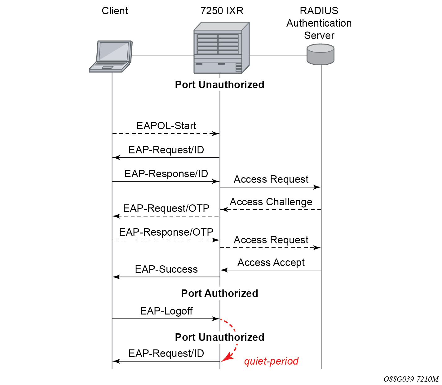
After receiving the EAP-Response/ID frame, the router encapsulates the identity information into a RADIUS AccessRequest packet, and sends it off to the configured RADIUS server.
The RADIUS server checks the supplied credentials, and if approved returns an Access Accept message to the router. The router notifies the client with an EAP-Success PDU and puts the port in authorized state.
802.1x modes
Nokia routers support port-based network access control for Ethernet ports only. Every Ethernet port can be configured to operate in one of three different operation modes, controlled by the port-control command:
force authorized
This mode disables 802.1x authentication and causes the port to transition to the authorized state without requiring any authentication exchange. The port transmits and receives normal traffic without requiring 802.1x-based host authentication. This is the default setting.
force unauthorized
This mode causes the port to remain in the unauthorized state, ignoring all attempts by the hosts to authenticate. The switch cannot provide authentication services to the host through the interface.
auto
This mode enables 802.1x authentication. The port starts in the unauthorized state, allowing only EAPOL frames to be sent and received through the port. Both the router and the host can initiate an authentication procedure as described below. The port remains in unauthorized state (no traffic except EAPOL frames is allowed) until the first client is authenticated successfully. After this, traffic is allowed on the port for all connected hosts.
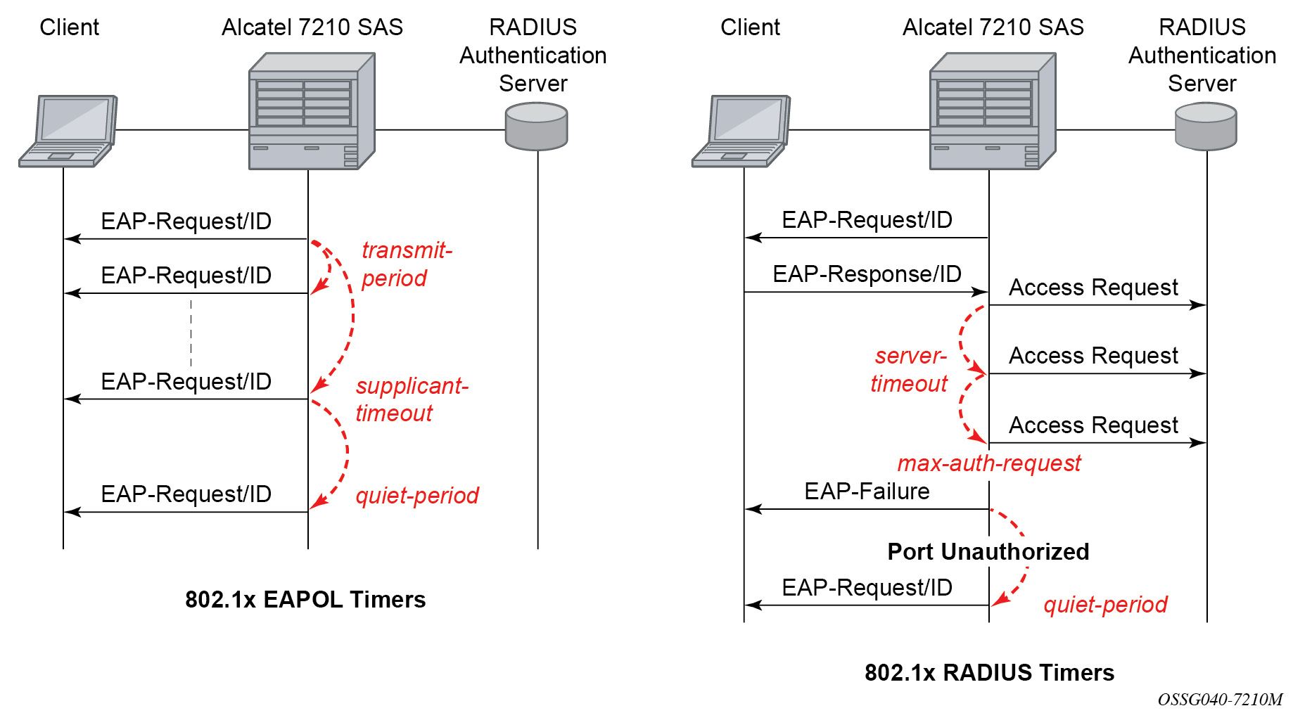
802.1x timers
The 802.1x authentication procedure is controlled by a number of configurable timers and scalars. There are two separate sets, one for the EAPOL message exchange and one for the RADIUS message exchange. See 802.1x EAPOL timers (left) and RADIUS timers (right) for an example of the timers on the 7750 SR.
EAPOL timers:
-
transmit-period
This timer indicates how many seconds the Authenticator listens for an EAP-Response/ID frame. If the timer expires, a new EAP-Request/ID frame is sent and the timer restarted. The default value is 60. The range is 1 to 3600 seconds.
-
supplicant-timeout
This timer is started at the beginning of a new authentication procedure (transmission of first EAP-Request/ID frame). If the timer expires before an EAP-Response/ID frame is received, the 802.1x authentication session is considered as having failed. The default value is 30. The range is 1 to 300.
-
quiet-period
This timer indicates number of seconds between authentication sessions. It is started after logout, after sending an EAP-Failure message or after expiry of the supplicant-timeout timer. The default value is 60. The range is 1 to 3600.
RADIUS timer and scalar:
-
maximum authentication requests
This scalar indicates the maximum number of times that the router sends an authentication request to the RADIUS server before the procedure is considered as having failed. The default value is value 2. The range is 1 to 10.
-
server timeout
This timer indicates how many seconds the authenticator waits for a RADIUS response message. If the timer expires, the access request message is sent again, up to maximum authentication request times. The default value is 60. The range is 1 to 3600 seconds.
The router can also be configured to periodically trigger the authentication procedure automatically. This is controlled by enabling re-authentication and re-authentication period. Re-authentication period indicates the period in seconds (since the last time that the authorization state was confirmed) before a new authentication procedure is started. The range of reauth-period is 1 to 9000 seconds (the default is 3600 seconds, one hour). Note that the port stays in an authorized state during the re-authentication procedure.
802.1x tunneling
Tunneling of untagged 802.1x frames received on a port is supported for both Epipe and VPLS service using either null or default SAPs (for example 1/1/1:*) when the following command is configured:
-
MD-CLI
configure port ethernet dot1x port-control force-authorized -
classic CLI
configure port ethernet dot1x port-control force-auth
When tunneling is enabled on a port, untagged 802.1x frames are treated like user frames and are switched into Epipe or VPLS services which have a corresponding null SAP or default SAP on that port. In the case of a default SAP, it is possible that other non-default SAPs are also present on the port. Untagged 802.1x frames received on other service types, or on network ports, are dropped. Use the following command to enable tunneling on a port.
configure port port-id ethernet dot1x tunnelingWhen tunneling is required, it is expected that it is enabled on all ports into which 802.1x frames are to be received. The configuration of dot1x must be configured consistently across all ports in LAG as this is not enforced by the system.
Note that 802.1x frames are treated like user frames, that is, tunneled, by default when received on a spoke or mesh SDP.
Per-host authentication
Per-host authentication enables SR OS to authenticate each host individually and allows or disallows the PDUs from this host through the port. Per-host authentication is configurable using the CLI.
When dot1x tunneling is disabled, the port does not allow any PDUs to pass through, with the exception of dot1x packets, which are extracted.
When per-host-authentication is configured on the port for dot1x, each host is authenticated individually according to the RADIUS policy and host traffic is allowed or disallowed through the port. After the first successful host authentication, the behavior is the following:
On downstream (that is, traffic from the network to the host), the port is authorized and allows all traffic to go through.
On upstream (that is, traffic from the host to the network), the port is authorized, but allows through traffic from the authenticated hosts only. When the host is allowed through the port, all PDUs for that host are allowed to pass through the port, including untagged or tagged packets. The traffic from any unauthenticated host is disallowed.
For per-host authentication, EAPOL packets are sent to the RADIUS server using the RADIUS protocol. The calling station identifier is the source MAC address of the host and is usually present in the packet. The identifier is used to allow or disallow the host source MAC address based on the RADIUS success or failure answer.
The hosts are authenticated periodically. If a host is authenticated and placed on the allow list and a subsequent authentication fails, that host is removed from the allow list.
If a host authenticates unsuccessfully multiple times, that host is put on a disallow list for a specific amount of time. That is, enabling per-host authentication provides per-host (source MAC) DoS mitigation.
Duplicate MAC addresses are not allowed on the port.
All logs display per-host authentication.
Per-host authentication interaction with dot1x
When per-host authentication is first enabled, all MAC addresses on the port are denied. The user can allow MAC addresses using the static source MAC or dot1x host authentication. The following considerations apply when dot1x authentication is used.
-
If the 802.1x authentication mode is configured as force authorized, any host that sends EAPOL frames is authenticated without requiring any exchange with the RADIUS server. Use the following command to configure force authorized:
-
MD-CLI
configure port ethernet dot1x port-control force-authorized -
classic CLI
configure port ethernet dot1x port-control force-auth
-
If configure system security dot1x is administratively disabled, the port behavior is the same as in the force authorized case:
-
MD-CLI
configure port ethernet dot1x admin-state disable -
classic CLI
configure port ethernet dot1x shutdown
-
-
If the 802.1x authentication mode is configured as auto, the hosts are authenticated using RADIUS. However, if configure system security dot1x is administratively disabled, the force authorized behavior takes effect.
Static allow source MAC
A host can be added to the Allow MAC list statically, without being authenticated using dot1x. In this case, the host source MAC address must be added manually using the CLI.
If the same host is added to the list using dot1x and the CLI, the static configuration takes precedence. If the host is added using the CLI, the host is placed on the Allow list. If the same host tries to authenticate using RADIUS and the authentication fails, the host is still allowed through the port because it was statically added using the following command.
configure port ethernet dot1x per-host-authentication allowed-source-macs mac-addressTagged dot1x authentication
Dot1x packets can arrive tagged or untagged on the authenticator port from the host. SR OS can be configured to tunnel or extract tagged dot1x packets. SR OS forwards tagged dot1x packets only.
The tunneling or extracting of tagged dot1x packets can be enabled for dot1q (tunnel-dot1q) and QinQ (tunnel-qinq) encapsulation types.
Each of the encapsulation types configured on the port can be configured to tunnel dot1x packets or extract dot1x packets to be authenticated using a configured RADIUS policy.
The extraction or tunneling of tagged packets applies to any tag value.
Dot1x and LAG
For dot1x authentication support, when the primary port member of the LAG is configured with dot1x, all members inherit the dot1x functionality. Dot1x packets can be extracted on any LAG member and sent to the RADIUS server for processing and authentication. After a successful authentication, the host is allowed on all LAG members. The host dot1x packets can be extracted on one LAG member, while the actual traffic traverses another LAG member. The following is the behavior of dot1x in a LAG bundle.
When ports are added to the LAG member and dot1x is enabled, all ports inherit the same dot1x configuration as the primary port on the LAG member.
If a host source address (SA) is authenticated through one of the LAG member ports, all ports on the LAG bundle are authorized and pass traffic.
When a new port is added to the LAG member, if the LAG bundle has been authenticated and is authorized, the new member is authorized as well.
-
Dot1x configuration changes are allowed on the primary LAG member only. A port can be added to a LAG only if its dot1x configuration aligns with that of the primary LAG member. If at least one LAG member is authorized, all LAG members are authorized.
In an upgrade scenario, when an older configuration file (admin save) is executed on a new release, a warning is displayed instead of an error for a command that violates the dot1x configuration change behavior; the violating command is ignored.
If a port is removed from the LAG bundle, the port becomes unauthorized and the EAP negotiation should authorize the port again. This is true for all ports in the LAG bundle, primary or not.
-
When Random Early Discard (RED) updates are received during an ISSU on a LAG member in standby, the following updates are ignored:
- enable dot1x on a LAG member
- authorize a LAG member
When a port is added to a LAG during ISSU, its dot1x configuration is reset to the default values.
SR host authentication behavior
SR allows the same MAC source address (MAC SA) on different ports if the MAC address is authenticated. Multiple hosts with the same MAC address can reside and get authenticated on different ports.
Authentication lists
The following authentication lists are supported:
authenticated host list
This list contains up to 1000 hosts. Only hosts that have been authenticated through RADIUS and are allowed through the port are included in this list.
-
unauthenticated host list
This list contains up to 2000 hosts. Only hosts that have failed authentication or are in the process of being authenticated are included in this list.
If this list reaches the 2000-host limit and a new host is being authenticated, the new host bumps off the list the first host that has failed authentication. The following sequence shows an example:
Unauthenticated list
Host 1 authenticating
Host 2 failed authentication
….
Host 2000 authenticating
Host 2001 just arrived, this host should bump Host 2 off in the list, not Host 1.
If all hosts are in authenticating state, the new Host 2001 is not allowed on the list.
802.1x configuration and limitations
Configuration of 802.1x network access control on the router consists of two parts:
generic command options, which are configured under configure system security dot1x
port-specific command options, which are configured under configure port ethernet dot1x
The following considerations apply:
- If per-host authentication is not configured, the authentication of any host on the port provides access to the port for any device, even if only a single client has been authenticated.
- 802.1x authentication can only be used to gain access to a pre-defined Service Access Point (SAP). It is not possible to dynamically select a service (such as a VPLS service) depending on the 802.1x authentication information.
- If 802.1x access control is enabled and a high rate of 802.1x frames are received on a port, that port is blocked for a period of 5 minutes as a DoS protection mechanism.
Disabling the 802.1x functionality on a port
By default, the 802.1x functionality consisting of packet extraction and processing on the CPM is enabled on each port.
Use the following command to administratively disable the 802.1x functionality on a port by not extracting the dot1x packets to the CPM.
-
MD-CLI
configure port ethernet dot1x admin-state disable -
classic CLI
configure port ethernet dot1x shutdown
Exponential Port Dampening
Exponential Port Dampening (EPD) provides the ability to automatically block a port from reuse for a period of time after physical link-down and physical link-up events. If a series of down-up events occur close together, EPD keeps the port’s operational state down for a longer period than if only one down-up event has occurred. The router avoids using that port if external events are causing the link state to fluctuate. The more events that occur, the longer the port is kept down and avoided by the routing protocols.
EPD behavior uses a fixed penalty amount per link-down event and a half-life decay equation to reduce these penalties over time. The following equation defines exponential decay:
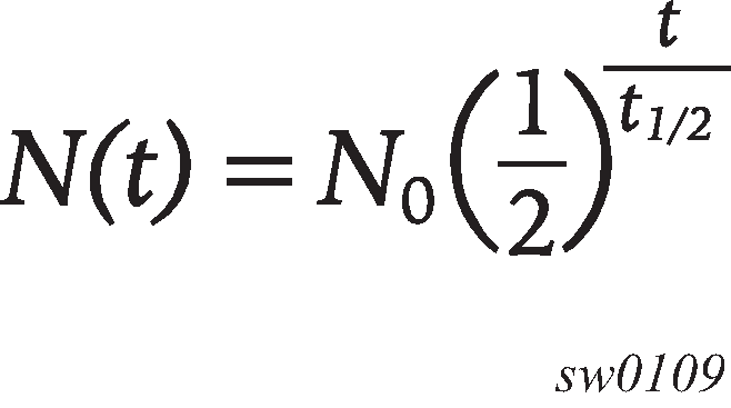
where:
N(t) is the quantity that still remains after a time t
N0 is the initial quantity
t½ is the half-life
In dampening, N0 refers to the starting penalties from the last link-down event. The quantity N(t) refers to the decayed penalties at a specific time, and is calculated starting from the last link-down event (that is, from the time when N0 last changed).
This equation can also be used on a periodic basis by updating the initial quantity value N0 each period and then computing the new penalty over the period (t).
The following figure shows an example usage of the EDP feature.
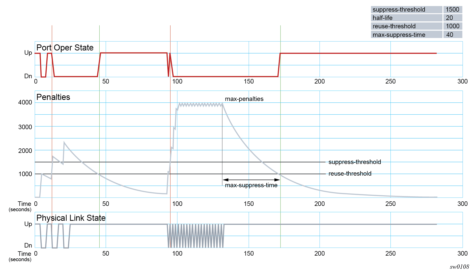
At time (t = 0) in the preceding figure, the initial condition has the link up, the accumulated penalties are zero, the dampening state is idle, and the port operational state is up. The following series of events and actions occur.
t = 5: link-down event
the accumulated penalties are incremented by 1000
the accumulated penalties now equal 1000, which is less than the suppress threshold (of 1500), so the dampening state is idle
because the dampening state is idle, link-down is passed to the upper layer
link-down triggers the port operational state to down
t = 9: link-up event
the accumulated penalties equal 869, which is less than the suppress threshold, so the dampening state remains as idle
because the dampening state is idle, link-up is passed to the upper layer
link-up triggers the port operational state to up
t = 13: link-down event
the accumulated penalties are incremented by 1000
the accumulated penalties now equal 1755, which is greater than the suppress threshold, so the dampening state is changed to active
because the dampening state just transitioned to active, link-down is passed to the upper layer
link-down triggers the port operational state to down
t = 17: link-up event
the accumulated penalties equal 1527, which is above the reuse threshold (of 1000) and greater than the suppress threshold, so the dampening state remains as active
because the dampening state is active, link-up is not passed to the upper layer
the port operational state remains down
t = 21: link-down event
the accumulated penalties are incremented by 1000
the accumulated penalties now equal 2327, which is above the reuse threshold, so the dampening state remains as active
because the dampening state is active, link-down is not passed to the upper layer
the port operational state remains down
t = 25: link-up event
the accumulated penalties equal 2024, which is above the reuse threshold, so dampening state remains as active
because the dampening state is active, link-up is not passed to the upper layer
the port operational state remains down
t = 46: accumulated penalties drop below the reuse threshold
the accumulated penalties drop below the reuse threshold, so the dampening state changes to idle
because the dampening state is idle and the current link state is up, link-up is passed to the upper layer
the port operational state changes to up
t = 94 to 133: link-down and link-up events every second
similar to previous events, the accumulated penalties increment on every link-down event
the dampening state transitions to active at t = 96, and link state events are not sent to the upper layer after that time
the upper layer keeps the port operational state down after t = 96
the accumulated penalties increment to a maximum of 4000
t = 133: final link event of link-up
the accumulated penalties equal 3863
the dampening state remains active and link state events are not sent to the upper layer
the upper layer keeps the port operational state down
t = 172: accumulated penalties drop below the reuse threshold
the accumulated penalties drop below the reuse threshold, so the dampening state changes to idle
because the dampening state is idle and the current link state is up, link-up is passed to the upper layer
the port operational state changes to up
Network synchronization on ports
Network synchronization on T1/E1 ports
Each T1/E1 port can be independently configured for loop-timing (recovered from an Rx line) or node-timing (recovered from the system synchronization unit (SSU) in the active control processing module (CPM)).
A T1/E1 port can be configured to be a timing source for the node.
Forward Error Correction
Users can use Forward Error Correction (FEC) on some ports to improve either the transmission reliability or reach, or both. FEC must always be used on some interface types while it is optional for other interface types. Also, some interface types allow more than one type of FEC. No matter what the setting of the FEC attributes, the transmitter and the receiver must have the same configuration, or the link will not work. The setting of FEC on a specific port is dependent on the interface type and the specific optical transceiver in use.
For coherent optics, the FEC (host and media) do not need to be configured and are automatically inherited and enabled based on the specific module and configured coherent mode of operation.