
Ports
Port types
Before a port can be configured, the slot must be provisioned with a card type and MDA type.
7705 SAR Gen 2 routers support the following port types:
-
Ethernet
Supported Ethernet port types include:
-
Fast Ethernet (10/100BASE-T, 100BASE-FX)
-
Gb Ethernet (1GbE, 1000BASE-T)
-
10 Gb Ethernet (10GbE, 10GBASE-X)
-
25 Gb Ethernet (25GBASE-R)
Router ports must be configured as either access, network, or hybrid. The default is network.
-
-
access
Access ports are configured with services to carry customer-facing traffic. If a Service Access Port (SAP) is required on a port or channel, it must first be configured as an access port or channel. When a port is configured for access mode, the appropriate encapsulation type must be configured to distinguish the services on the port or channel. After a port has been configured for access mode, one or more services can be configured on the port or channel, depending on the encapsulation value.
-
network
Network ports are configured for network-facing traffic. These ports participate in the service provider transport or infrastructure network. Dot1q is supported on network ports.
-
hybrid
Hybrid ports are configured for access and network-facing traffic. While the default mode of an Ethernet port remains network, the port cannot change between access, network, and hybrid modes unless the port is first shut down and any configured SAPs or interfaces are deleted.
Hybrid ports can operate in both access and network modes. The MTU of a port in hybrid mode is the same as in network mode. The default encapsulation for hybrid port mode is dot1q; the port also supports QinQ encapsulation. Null hybrid port mode is not supported. After the port is changed to hybrid, the default MTU is changed to 9212 bytes, the value currently used in network mode (higher than an access port). This ensures that both SAP and network VLANs are accommodated. The only exception applies to 10/100 Fast Ethernet ports operating in hybrid mode. In those cases, this is set to 1522 bytes, which corresponds to the default access MTU with QinQ, and is larger than the network dot1q MTU or the access dot1q MTU for this type of Ethernet port.
All command options in the access and network contexts can be configured within the port using the same CLI hierarchy as in the existing implementation. The difference is that a port configured in hybrid mode allows both ingress and egress contexts to be configured concurrently.
An Ethernet port configured in hybrid mode can have two encapsulation types: dot1q and QinQ. The NULL value is not supported because a single SAP is allowed. This can be achieved by configuring the port in access mode, or by allowing a single network IP interface achieved by configuring the port in network mode.
Hybrid mode can be enabled on a LAG port when the port is part of a single-chassis LAG configuration. When the port is part of a multichassis LAG configuration, it can only be configured to access mode because MC-LAG is not supported on network ports and, consequently, not supported on hybrid ports. The same restriction applies to a port that is part of an MC-Ring configuration.
For a hybrid port, use the following commands to split the amount of allocated port buffers for ingress and egress equally between network and access contexts:
-
MD-CLI
configure port hybrid-buffer-allocation ingress-weight access network configure port hybrid-buffer-allocation egress-weight access network -
classic CLI
configure port hybrid-buffer-allocation ing-weight access network
configure port hybrid-buffer-allocation egr-weight access network
Adapting the terminology in buffer-pools, the access active bandwidth and network active bandwidth of the port are derived in each ingress and egress as follows (egress formulas shown only):
-
total-hybrid-port-egress-weights = access-weight + network-weight
-
hybrid-port-access-egress-factor = access-weight / total-hybrid-port-egress-weights
-
hybrid-port-network-egress-factor = network-weight / total-hybrid-port-egress-weights
-
port-access-active-egress-bandwidth = port-active-egress-bandwidth x hybrid-port-access-egress-factor
-
port-network-active-egress-bandwidth = port-active-egress-bandwidth x hybrid-port-network-egress-factor
-
-
GNSS receiver
The 7705 SAR-Hx and 7705 SAR-Mx are equipped with an integrated Global Navigation Satellite System (GNSS) receiver and GNSS radio frequency (RF) port for retrieval and recovery of GPS and Galileo signals.
Note: Signal recovery must always be enabled in the system configuration when the GNSS receiver is used.See the 7705 SAR Gen 2 Basic System Configuration Guide for information about using a GNSS receiver as a timing source for the node.
-
WAN PHY
Note: WAN mode is not supported on the 7705 SAR Gen 2.10 G Ethernet ports can be configured in WAN PHY mode. Use commands in the following context to configure 10 G Ethernet ports in WAN PHY mode.
configure port ethernet xgigWhen configuring the port in WAN mode, you can change specific SONET/SDH command options to reflect the SONET/SDH requirements for this port.
-
TDM
Time-Division Multiplexing (TDM) ports support access mode only. Supported TDM port types on the 7705 SAR-Hx and 7705 SAR-Mx include:
-
T1
-
E1
-
C37.94
-
-
LAG
A Link Aggregation Group (LAG) can be used to group multiple ports into one logical link. The aggregation of multiple physical links enables load sharing and provides seamless redundancy. If one link fails, traffic is redistributed over the remaining links.
-
connector
A connector that can accept transceiver modules, including breakout connectors to multiple physical ports. For example, an SFP28 connector can support 1Gb, 10 Gb, and 25 Gb Ethernet ports, depending on the port speed mode configuration. The connectors themselves cannot be used as ports in other commands; however, the breakout ports can be used as any Ethernet port.
See Ethernet ports for more information.
Ethernet ports
This section provides information about the supported Ethernet ports and pluggable transceiver types for 7705 SAR Gen 2 platforms.
The following table lists the supported speeds for pluggable transceiver types.
| Pluggable transceiver type | Supported speeds |
|---|---|
| SFP |
SFP transceivers support speeds of 1 Gb/s, unless 100 Mb/s support is noted in other table footnotes. |
| SFP+ | SFP+ transceivers support speeds of 10 Gb/s. |
| SFP28 | SFP28 transceivers support speeds of 25 Gb/s. |
The following table lists the supported port types and pluggable transceivers for 7705 SAR Gen 2 platforms.
| 7705 SAR Gen 2 hardware |
Physical port type |
Accepted pluggable transceivers | |||
|---|---|---|---|---|---|
| SFP 1 | SFP+ | SFP28 | |||
| 7705 SAR-1 | |||||
| m10-sfp++6-sfp | SFP | ✓ | — | — | |
| SFP+ | ✓ | ✓ | — | ||
| 7705 SAR-Hx and 7705 SAR-Mx | |||||
| m4-1g-rj+6-10g-sfp++2-25g-sfp28 | SFP+ | ✓ | ✓ | — | |
| SFP28 | ✓ | ✓ | ✓ | ||
| RJ45 2 | — | — | — | ||
| m2-1g-sfp+2-10g-sfp+ | SFP | ✓ | — | — | |
| SFP+ | ✓ | ✓ | — | ||
| m8-1g-sfp | SFP | ✓ | — | — | |
| m8-1g-rj45 2 | RJ45 | — | — | — | |
Port speeds on the 7705 SAR-Hx and 7705 SAR-Mx
The following table lists the supported port speeds on 7705 SAR-Hx and 7705 SAR-Mx MDAs.
- MACSec
- Precision Time Protocol (PTP)
- Synchronous Ethernet (SyncE)
| MDA | Port or pluggable transceiver type | Port ID | Supported speeds |
|---|---|---|---|
| m4-1g-rj+6-10g-sfp++2-25g-sfp28 | RJ45 | 1/2/1 to 1/2/4 | 10M/100M/1000M |
| SFP | 1/2/c5 to 1/2/c12 | 100M/1G 1 2 | |
| SFP+ | 10G | ||
| SFP28 | 1/2/c11 to 1/2/c12 | 25G | |
| m2-1g-sfp+2-10g-sfp+ | SFP | 1/1/c1 to 1/1/c4 | 100M/1G 3 4 |
| SFP+ | 1/1/c3 to 1/1/c4 | 10G | |
| m8-1g-sfp | SFP | 1/1/c1 to 1/1/c8 | 10M/100M/1G 5 6 |
| m8-1g-rj45 | RJ45 | 1/1/1 to 1/1/8 | 10M/100M/1000M |
Port speed modes
- MD-CLI
admin system port-speed-mode mode - classic
CLI
admin system port-speed-mode
The following table lists the supported port speeds in each speed mode.
| Speed mode | Port and port type | |
|---|---|---|
| 1/2/c5 to 1/2/c10 | 1/2/c11 to 1/2/c12 | |
| SFP or SFP+ | SFP, SFP+, or SFP28 | |
|
Speed mode 1 1G/10G |
100M/1G/10G |
1G/10G |
|
Speed mode 2 10G/25G |
10G | 10G/25G |
TDM
TDM ports are supported on the following MDAs:
8-port T1/E1 ASAP Adapter card
T1/E1 port configuration is available on the 8-port T1/E1 ASAP Adapter card supported on the 7705 SAR-Hx and 7705 SAR-Mx.
On T1/E1 ports, channelization is supported down to the DS0 level. To change port types, all ports must first be administratively disabled. The ports can be configured for T1 and E1 operations. When the first port on a card is configured, all other ports on the card must be set to the same type.
T1/E1 ports support only cem encapsulation.
8-port RS-232 and C37.94 combination MDA
This MDA is supported on the 7705 SAR-Hx and 7705 SAR-Mx.
On the 8-port RS-232 and C37.94 combination MDA, channelization is supported down to the DS0 level on the four RS-232 serial ports and four IEEE C37.94 teleprotection interface (TPIF) ports.
The RS-232 and C37.94 ports are used in critical networks for applications like SCADA and teleprotection.
Port features
Port State and Operational State
There are two port attributes that are related and similar but have slightly different meanings: Port State and Operational State (or Operational Status).
The following descriptions are based on normal individual ports. Many of the same concepts apply to other objects that are modeled as ports in the router such as APS groups but the show output descriptions for these objects should be consulted for the details.
-
Port State
-
Displayed in port summaries such as show port or show port 1/1
-
tmnxPortState in the TIMETRA-PORT-MIB
-
Values: None, Ghost, Down (linkDown), Link Up, Up
-
-
Operational State
-
Displayed in the show output of a specific port such as show port 2/1/3
-
tmnxPortOperStatus in the TIMETRA-PORT-MIB
-
Values: Up (inService), Down (outOfService)
-
The behavior of Port State and Operational State are different for a port with link protocols configured (for example, LACP for Ethernet ports). A port with link protocols configured only transitions to the Up Port State when the physical link is up and all the configured protocols are up. A port with no link protocols configured transitions from Down to Link Up and then to Up immediately after the physical link layer is up.
The linkDown and linkUp log events (events 2004 and 2005 in the SNMP application group) are associated with transitions of the port Operational State. Note that these events map to the RFC 2863, The Interfaces Group MIB, (which obsoletes RFC 2233, The Interfaces Group MIB using SMIv2) linkDown and linkUp traps as mentioned in the SNMPv2-MIB.
An Operational State of Up indicates that the port is ready to transmit service traffic (the port is physically up and any configured link protocols are up). The relationship between port Operational State and Port State is shown in Relationship of Port state and Oper state.
|
Port state |
Operational state (Oper state or Oper status) (as displayed in ‟show port x/y/z”) | |
|---|---|---|
|
Port State (as displayed in the show port summary) |
For ports that have no link layer protocols configured |
For ports that have link layer protocols configured (PPP, LACP, 802.3ah EFM, 802.1ag Eth-CFM) |
|
Up |
Up |
Up |
|
Link Up (indicates the physical link is ready) |
Up |
Down |
|
Down |
Down |
Down |
802.1x network access control
Nokia routers support network access control of client devices (PCs, STBs, and so on) on an Ethernet network using the IEEE. 802.1x standard. 802.1x is known as Extensible Authentication Protocol (EAP) over a LAN network or EAPOL.
802.1x basics
The IEEE 802.1x standard defines three participants in an authentication conversation (see 802.1x architecture that shows an example with the 7705 SAR Gen 2).
- the supplicant
- the end-user device that requests access to the network
- the authenticator
- controls access to the network. Both the supplicant and the authenticator are referred to as Port Authentication Entities (PAEs).
- the authentication server
- performs the actual processing of the user information
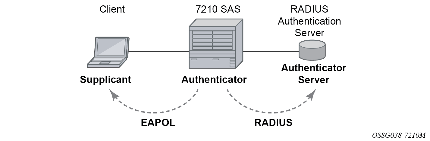
The authentication exchange is carried out between the supplicant and the authentication server, the authenticator acts only as a bridge. The communication between the supplicant and the authenticator is done through the Extended Authentication Protocol (EAP) over LANs (EAPOL). On the back end, the communication between the authenticator and the authentication server is done with the RADIUS protocol. The authenticator is therefore a RADIUS client, and the authentication server a RADIUS server.
The messages involved in the authentication procedure are shown in 802.1x authentication scenario. The router initiates the procedure when the Ethernet port becomes operationally up, by sending a special PDU called EAP-Request/ID to the client. The client can also initiate the exchange by sending an EAPOL-start PDU, if it does not receive the EAP-Request/ID frame during bootup. The client responds on the EAP-Request/ID with a EAP-Response/ID frame, containing its identity (typically username + password).
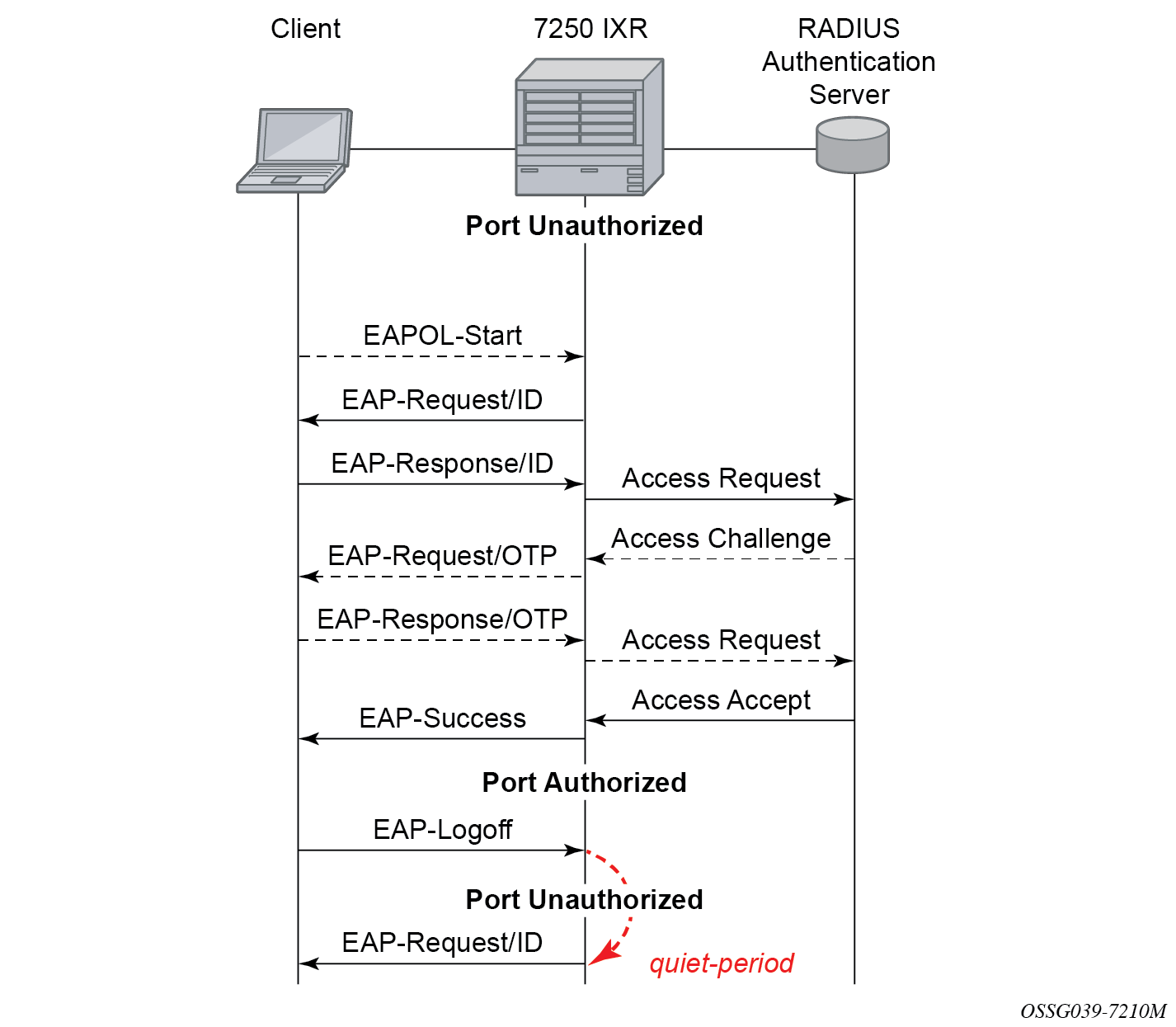
After receiving the EAP-Response/ID frame, the router encapsulates the identity information into a RADIUS AccessRequest packet, and sends it off to the configured RADIUS server.
The RADIUS server checks the supplied credentials, and if approved returns an Access Accept message to the router. The router notifies the client with an EAP-Success PDU and puts the port in authorized state.
802.1x modes
Nokia routers support port-based network access control for Ethernet ports only. Every Ethernet port can be configured to operate in one of three different operation modes, controlled by the port-control command:
force authorized
This mode disables 802.1x authentication and causes the port to transition to the authorized state without requiring any authentication exchange. The port transmits and receives normal traffic without requiring 802.1x-based host authentication. This is the default setting.
force unauthorized
This mode causes the port to remain in the unauthorized state, ignoring all attempts by the hosts to authenticate. The switch cannot provide authentication services to the host through the interface.
auto
This mode enables 802.1x authentication. The port starts in the unauthorized state, allowing only EAPOL frames to be sent and received through the port. Both the router and the host can initiate an authentication procedure as described below. The port remains in unauthorized state (no traffic except EAPOL frames is allowed) until the first client is authenticated successfully. After this, traffic is allowed on the port for all connected hosts.
802.1x timers
The 802.1x authentication procedure is controlled by a number of configurable timers and scalars. There are two separate sets, one for the EAPOL message exchange and one for the RADIUS message exchange. See 802.1x EAPOL timers (left) and RADIUS timers (right) for an example of the timers on the 7750 SR.
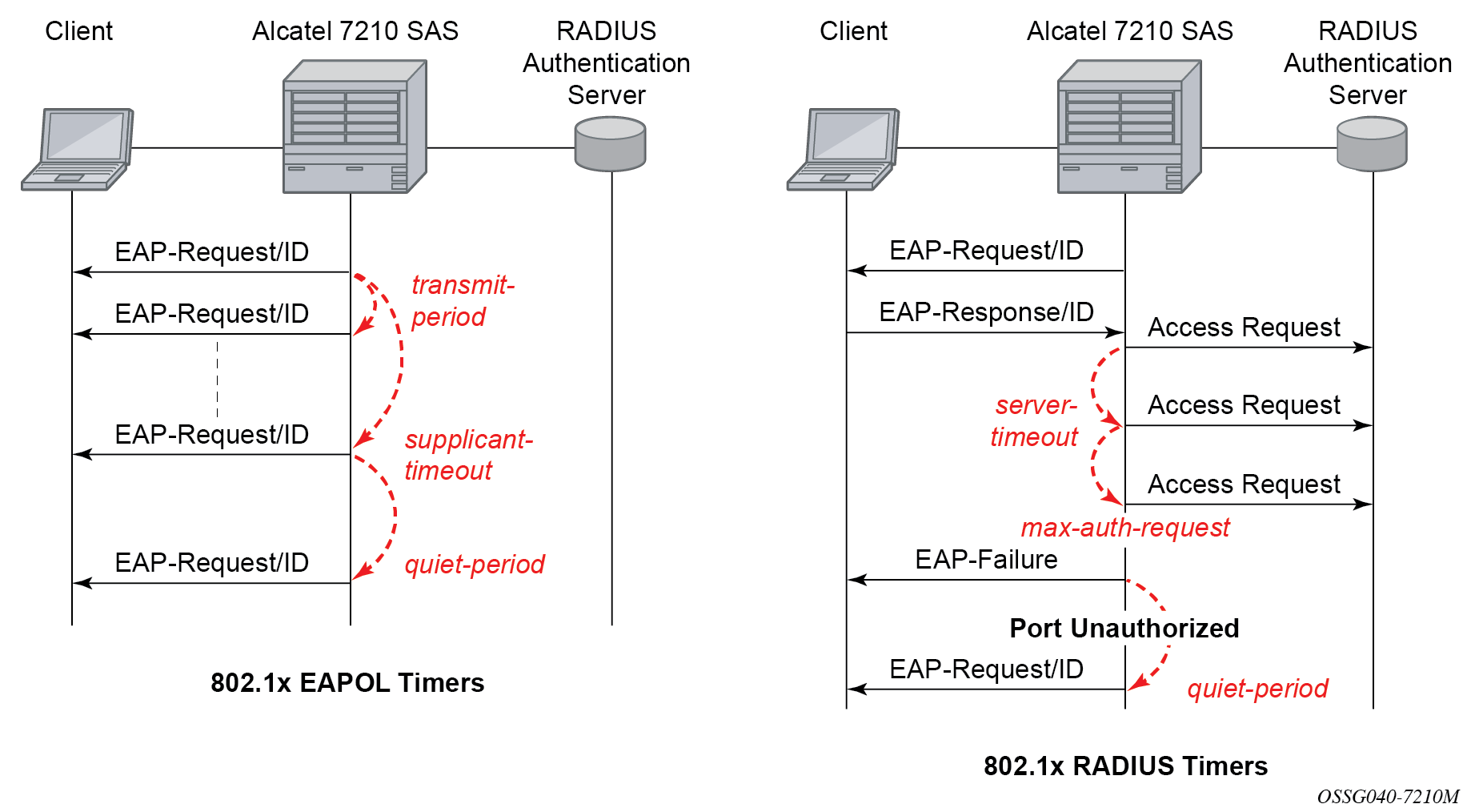
EAPOL timers:
-
transmit-period
This timer indicates how many seconds the Authenticator listens for an EAP-Response/ID frame. If the timer expires, a new EAP-Request/ID frame is sent and the timer restarted. The default value is 60. The range is 1 to 3600 seconds.
-
supplicant-timeout
This timer is started at the beginning of a new authentication procedure (transmission of first EAP-Request/ID frame). If the timer expires before an EAP-Response/ID frame is received, the 802.1x authentication session is considered as having failed. The default value is 30. The range is 1 to 300.
-
quiet-period
This timer indicates number of seconds between authentication sessions. It is started after logout, after sending an EAP-Failure message or after expiry of the supplicant-timeout timer. The default value is 60. The range is 1 to 3600.
RADIUS timer and scalar:
-
maximum authentication requests
This scalar indicates the maximum number of times that the router sends an authentication request to the RADIUS server before the procedure is considered as having failed. The default value is value 2. The range is 1 to 10.
-
server timeout
This timer indicates how many seconds the authenticator waits for a RADIUS response message. If the timer expires, the access request message is sent again, up to maximum authentication request times. The default value is 60. The range is 1 to 3600 seconds.
The router can also be configured to periodically trigger the authentication procedure automatically. This is controlled by enabling re-authentication and re-authentication period. Re-authentication period indicates the period in seconds (since the last time that the authorization state was confirmed) before a new authentication procedure is started. The range of reauth-period is 1 to 9000 seconds (the default is 3600 seconds, one hour). Note that the port stays in an authorized state during the re-authentication procedure.
802.1x tunneling
Tunneling of untagged 802.1x frames received on a port is supported for both Epipe and VPLS service using either null or default SAPs (for example 1/1/1:*) when the following command is configured:
-
MD-CLI
configure port ethernet dot1x port-control force-authorized -
classic CLI
configure port ethernet dot1x port-control force-auth
When tunneling is enabled on a port, untagged 802.1x frames are treated like user frames and are switched into Epipe or VPLS services which have a corresponding null SAP or default SAP on that port. In the case of a default SAP, it is possible that other non-default SAPs are also present on the port. Untagged 802.1x frames received on other service types, or on network ports, are dropped. Use the following command to enable tunneling on a port.
configure port port-id ethernet dot1x tunnelingWhen tunneling is required, it is expected that it is enabled on all ports into which 802.1x frames are to be received. The configuration of dot1x must be configured consistently across all ports in LAG as this is not enforced by the system.
Note that 802.1x frames are treated like user frames, that is, tunneled, by default when received on a spoke or mesh SDP.
Per-host authentication
Per-host authentication enables SR OS to authenticate each host individually and allows or disallows the PDUs from this host through the port. Per-host authentication is configurable using the CLI.
When dot1x tunneling is disabled, the port does not allow any PDUs to pass through, with the exception of dot1x packets, which are extracted.
When per-host-authentication is configured on the port for dot1x, each host is authenticated individually according to the RADIUS policy and host traffic is allowed or disallowed through the port. After the first successful host authentication, the behavior is the following:
On downstream (that is, traffic from the network to the host), the port is authorized and allows all traffic to go through.
On upstream (that is, traffic from the host to the network), the port is authorized, but allows through traffic from the authenticated hosts only. When the host is allowed through the port, all PDUs for that host are allowed to pass through the port, including untagged or tagged packets. The traffic from any unauthenticated host is disallowed.
For per-host authentication, EAPOL packets are sent to the RADIUS server using the RADIUS protocol. The calling station identifier is the source MAC address of the host and is usually present in the packet. The identifier is used to allow or disallow the host source MAC address based on the RADIUS success or failure answer.
The hosts are authenticated periodically. If a host is authenticated and placed on the allow list and a subsequent authentication fails, that host is removed from the allow list.
If a host authenticates unsuccessfully multiple times, that host is put on a disallow list for a specific amount of time. That is, enabling per-host authentication provides per-host (source MAC) DoS mitigation.
Duplicate MAC addresses are not allowed on the port.
All logs display per-host authentication.
Per-host authentication interaction with dot1x
When per-host authentication is first enabled, all MAC addresses on the port are denied. The user can allow MAC addresses using the static source MAC or dot1x host authentication. The following considerations apply when dot1x authentication is used.
-
If the 802.1x authentication mode is configured as force authorized, any host that sends EAPOL frames is authenticated without requiring any exchange with the RADIUS server. Use the following command to configure force authorized:
-
MD-CLI
configure port ethernet dot1x port-control force-authorized -
classic CLI
configure port ethernet dot1x port-control force-auth
-
If configure system security dot1x is administratively disabled, the port behavior is the same as in the force authorized case:
-
MD-CLI
configure port ethernet dot1x admin-state disable -
classic CLI
configure port ethernet dot1x shutdown
-
-
If the 802.1x authentication mode is configured as auto, the hosts are authenticated using RADIUS. However, if configure system security dot1x is administratively disabled, the force authorized behavior takes effect.
Static allow source MAC
A host can be added to the Allow MAC list statically, without being authenticated using dot1x. In this case, the host source MAC address must be added manually using the CLI.
If the same host is added to the list using dot1x and the CLI, the static configuration takes precedence. If the host is added using the CLI, the host is placed on the Allow list. If the same host tries to authenticate using RADIUS and the authentication fails, the host is still allowed through the port because it was statically added using the following command.
configure port ethernet dot1x per-host-authentication allowed-source-macs mac-addressTagged dot1x authentication
Dot1x packets can arrive tagged or untagged on the authenticator port from the host. SR OS can be configured to tunnel or extract tagged dot1x packets. SR OS forwards tagged dot1x packets only.
The tunneling or extracting of tagged dot1x packets can be enabled for dot1q (tunnel-dot1q) and QinQ (tunnel-qinq) encapsulation types.
Each of the encapsulation types configured on the port can be configured to tunnel dot1x packets or extract dot1x packets to be authenticated using a configured RADIUS policy.
The extraction or tunneling of tagged packets applies to any tag value.
Dot1x and LAG
For dot1x authentication support, when the primary port member of the LAG is configured with dot1x, all members inherit the dot1x functionality. Dot1x packets can be extracted on any LAG member and sent to the RADIUS server for processing and authentication. After a successful authentication, the host is allowed on all LAG members. The host dot1x packets can be extracted on one LAG member, while the actual traffic traverses another LAG member. The following is the behavior of dot1x in a LAG bundle.
When ports are added to the LAG member and dot1x is enabled, all ports inherit the same dot1x configuration as the primary port on the LAG member.
If a host source address (SA) is authenticated through one of the LAG member ports, all ports on the LAG bundle are authorized and pass traffic.
When a new port is added to the LAG member, if the LAG bundle has been authenticated and is authorized, the new member is authorized as well.
-
Dot1x configuration changes are allowed on the primary LAG member only. A port can be added to a LAG only if its dot1x configuration aligns with that of the primary LAG member. If at least one LAG member is authorized, all LAG members are authorized.
In an upgrade scenario, when an older configuration file (admin save) is executed on a new release, a warning is displayed instead of an error for a command that violates the dot1x configuration change behavior; the violating command is ignored.
If a port is removed from the LAG bundle, the port becomes unauthorized and the EAP negotiation should authorize the port again. This is true for all ports in the LAG bundle, primary or not.
-
When Random Early Discard (RED) updates are received during an ISSU on a LAG member in standby, the following updates are ignored:
- enable dot1x on a LAG member
- authorize a LAG member
When a port is added to a LAG during ISSU, its dot1x configuration is reset to the default values.
SR host authentication behavior
SR allows the same MAC source address (MAC SA) on different ports if the MAC address is authenticated. Multiple hosts with the same MAC address can reside and get authenticated on different ports.
Authentication lists
The following authentication lists are supported:
authenticated host list
This list contains up to 1000 hosts. Only hosts that have been authenticated through RADIUS and are allowed through the port are included in this list.
-
unauthenticated host list
This list contains up to 2000 hosts. Only hosts that have failed authentication or are in the process of being authenticated are included in this list.
If this list reaches the 2000-host limit and a new host is being authenticated, the new host bumps off the list the first host that has failed authentication. The following sequence shows an example:
Unauthenticated list
Host 1 authenticating
Host 2 failed authentication
….
Host 2000 authenticating
Host 2001 just arrived, this host should bump Host 2 off in the list, not Host 1.
If all hosts are in authenticating state, the new Host 2001 is not allowed on the list.
802.1x configuration and limitations
Configuration of 802.1x network access control on the router consists of two parts:
generic command options, which are configured under configure system security dot1x
port-specific command options, which are configured under configure port ethernet dot1x
The following considerations apply:
- If per-host authentication is not configured, the authentication of any host on the port provides access to the port for any device, even if only a single client has been authenticated.
- 802.1x authentication can only be used to gain access to a pre-defined Service Access Point (SAP). It is not possible to dynamically select a service (such as a VPLS service) depending on the 802.1x authentication information.
- If 802.1x access control is enabled and a high rate of 802.1x frames are received on a port, that port is blocked for a period of 5 minutes as a DoS protection mechanism.
Disabling the 802.1x functionality on a port
By default, the 802.1x functionality consisting of packet extraction and processing on the CPM is enabled on each port.
Use the following command to administratively disable the 802.1x functionality on a port by not extracting the dot1x packets to the CPM.
-
MD-CLI
configure port ethernet dot1x admin-state disable -
classic CLI
configure port ethernet dot1x shutdown
MACsec
Media Access Control Security (MACsec) is an industry-standard security technology that provides secure communication for almost all types of traffic on Ethernet links. MACsec provides point-to-point and point-to-multipoint security on Ethernet links between directly connected nodes or nodes connected via a Layer 2 cloud. MACsec can identify and prevent most security threats, including:
denial of service
intrusion
man-in-the-middle
masquerading
passive wiretapping
playback attacks
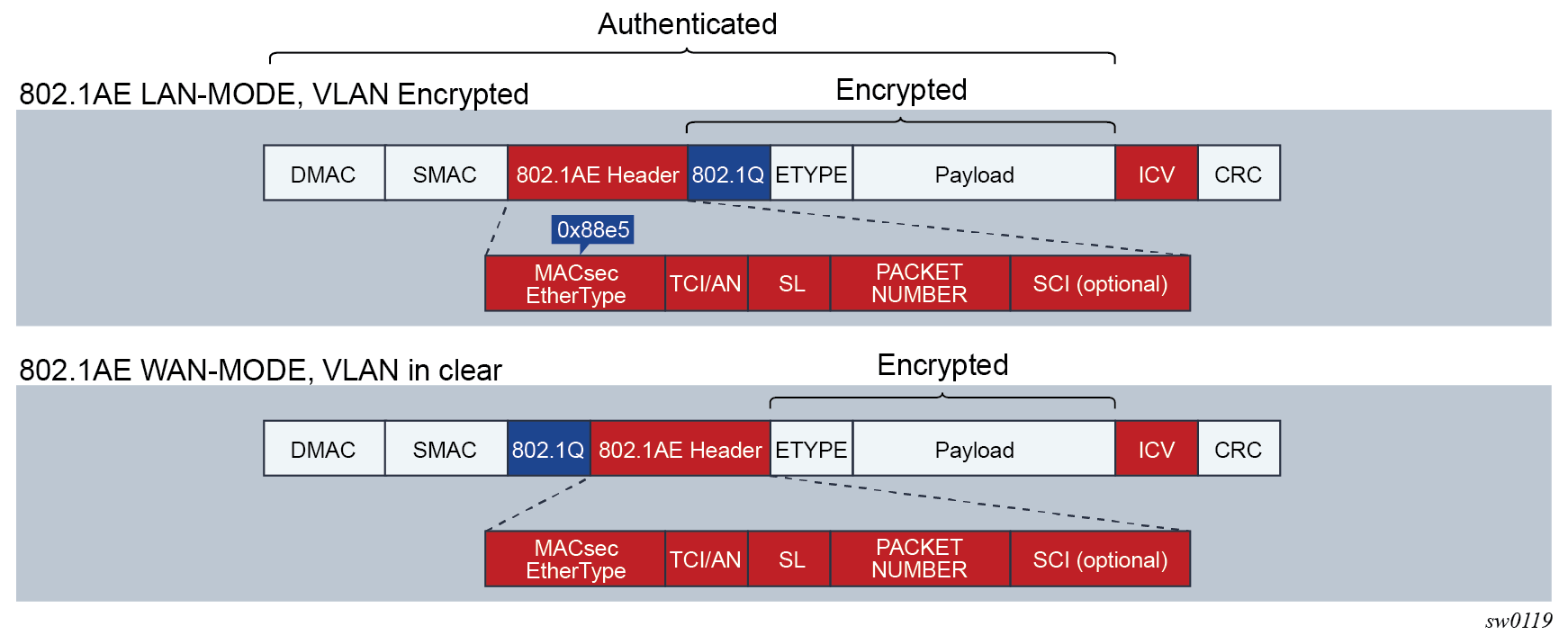
MACsec Layer 2 encryption is standardized in IEEE 802.1AE. MACsec encrypts anything from the 802.1AE header to the end of the payload, including 802.1Q; it leaves the DMAC and SMAC in cleartext.
The following figure shows the 802.1AE LAN-Mode structure.
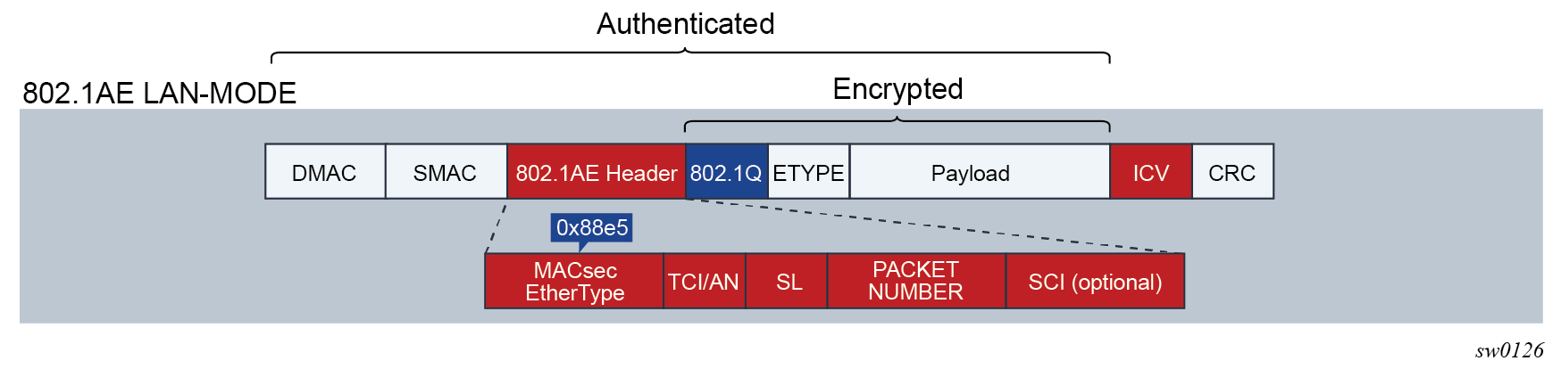
The destination MAC address, which is in cleartext, is used for MACsec packet forwarding.
MACsec 802.1AE header — security TAG
The MACsec 802.1AE header includes a security TAG (SecTAG) field that contains the following information:
association number within the channel
packet number to provide a unique initialization vector for encryption and authentication algorithms, as well as protection against replay attacks
optional LAN-wide secure channel identifier
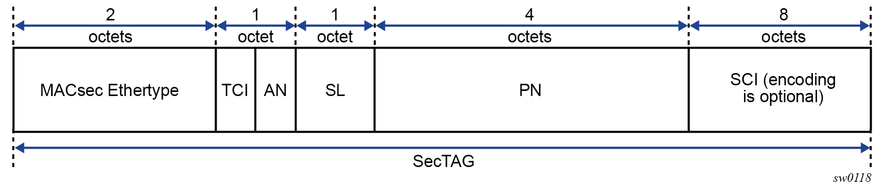
The SecTAG field, which is identified by the MACsec EtherType, conveys the following information:
TAG Control Information (TCI)
Association Number (AN)
Short Length (SL)
Packet Number (PN)
Optionally-encoded Secure Channel Identifier (SCI)
The following figure shows the format of the SecTAG field.
MACsec encryption mode
The main modes of encryption in MACsec are:
VLAN in cleartext (WAN Mode)
VLAN encrypted
802.1AE dictates that the 802.1Q VLAN must be encrypted. Some vendors provide the option of configuring the MACsec on a port with VLAN in cleartext.
SR OS supports both modes.
The following figure shows the encrypted VLAN and the VLAN in cleartext.
MACsec encryption per traffic flow encapsulation matching
MACsec can be applied to a selected subset of the port traffic, based on the type and value of the packet encapsulation. The SR OS can be configured to match and encrypt the following traffic encapsulation types:
-
all encapsulated traffic arriving on the port, including untagged, single-tag, and double-tag. This is the default MACsec behavior.
untagged only traffic
single-tag or dot1q traffic. In this mode, MACsec can apply to a specific tag or a wildcard tag where all single-tag traffic is matched.
double-tag or QinQ traffic. In this mode, MACsec can apply to a specific service tag, a specific service and customer tag, or a wildcard for any QinQ traffic.
MKA PDUs are generated specifically for the traffic-encapsulation type that is being matched.
MACsec key management modes
The following table describes the main key management modes in MACsec.
| Keying | Explanation | SR OS support | Where used |
|---|---|---|---|
Static SAK |
Manually configures each node with a static SAK, SAM, or CLI |
Switch to switch |
|
Static CAK PRE SHARED KEY |
Uses a dynamic MACsec Key Management (MKA) and a configured pre-shared key to drive the CAK. The CAK encrypts the SAK between two peers and authenticates the peers. |
✓ |
Switch to switch |
Dynamic CAK EAP Authentication |
Uses a dynamic MKA and an EAP Master System Key (MSK) to drive the CAK. The CAK encrypts the SAK between two peers and authenticates the peers. |
Switch to switch |
|
Dynamic CAK MSK distribution via RADIUS and EAP-TLS |
Stores the MSKs in the Radius server and distributes to the hosts via EAP-TLS. This is typically used in the access networks where a large number of hosts use MACsec and connect to an access switch. MKA uses MSK to drive the CAK. The CAK encrypts the SAK between 2 peers and authenticates the peers. |
Host to switch |
MACsec terminology
The following figure shows the main concepts used in MACsec for the static-CAK scenario.
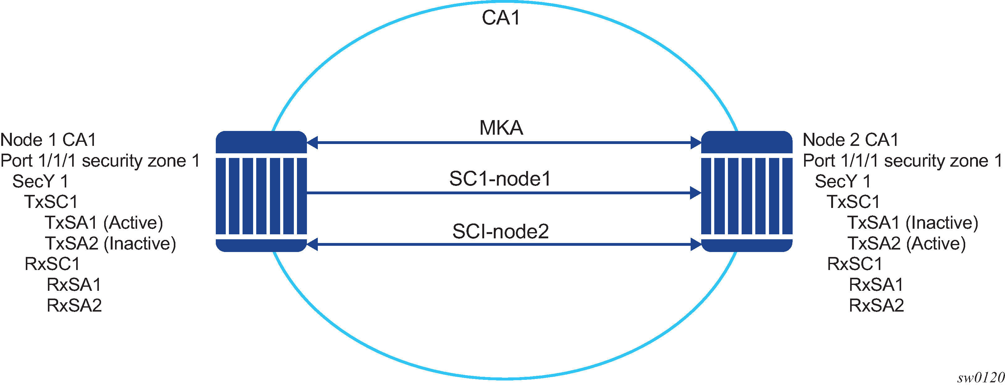
The following table describes MACsec terminology.
| MACsec term | Description |
|---|---|
Connectivity Association (CA) |
Provides a security relationship, established and maintained by key agreement protocols (MKA), that comprises a fully connected subset of the SAPs in stations attached to a single LAN that are to be supported by MACsec. |
MACsec Key Agreement (MKA) Protocol |
Provides a control protocol between MACsec peers, which is used for peer aliveness and encryption key distribution. MKA is responsible for discovering, authenticating, and authorizing the potential participants in a CA. |
|
MAC Security Entity (SecY) |
Operates the MAC security protocol within a system. Manages and identifies the SC and corresponding active SA. |
Security Channel (SC) |
Provides a unidirectional point-to-point or point-to-multipoint communication. Each SC contains a succession of SAs, and each SC has a different SAK. |
Security Association (SA) |
In the cases of SR OS with two SAs per SC, each with a different SAK, each SC comprises a succession of SAs. Each SA is identified by the SC identifier, concatenated with a two-bit association number. The Secure Association Identifier (SAI) that is created allows the receiving SecY to identify the SA and the SAK used to decrypt and authenticate the received frame. The AN, and consequently the SAI, is only unique for the SAs that can be used or recorded by participating SecYs at any time. The MKA creates and distributes SAKs to each of the SecYs in a CA. This key creation and distribution is independent of the cryptographic operation of each of the SecYs. The decision to replace one SA with its successor is made by the SecY that transmits using the SC, after the MKA has informed it that all the other SecYs are prepared to receive using that SA. No notification, other than receipt of a secured frame with a different SAI is sent to the receiver. A SecY must always be capable of storing SAKs for two SAs for each inbound SC, and of swapping from one SA to another without notice. Certain LAN technologies can reorder frames of different priority, so reception of frames on a single SC can use interleaved SA. |
Security Association Key (SAK) |
Provides the encryption key used to encrypt the MACsec datapath. |
MACsec static CAK
MACsec uses SAs to encrypt packets. SA is a security relationship that provides security guarantees for frames transmitted from one member of a CA to the others. Each SA contains a single secret key (SAK) used to perform the cryptographic operations that encrypt the datapath PDUs.
SAK is the secret key used by an SA to encrypt the channel.
When enabled, MACsec uses a static CAK security mode. Two security keys, a connectivity association key (CAK) that secures control plane traffic, and a randomly generated secure association key (SAK) that secures data plane traffic, are used to secure the point-to-point or point-to-multipoint Ethernet link. Both keys are regularly exchanged between both devices on each end of the Ethernet link to ensure link security.
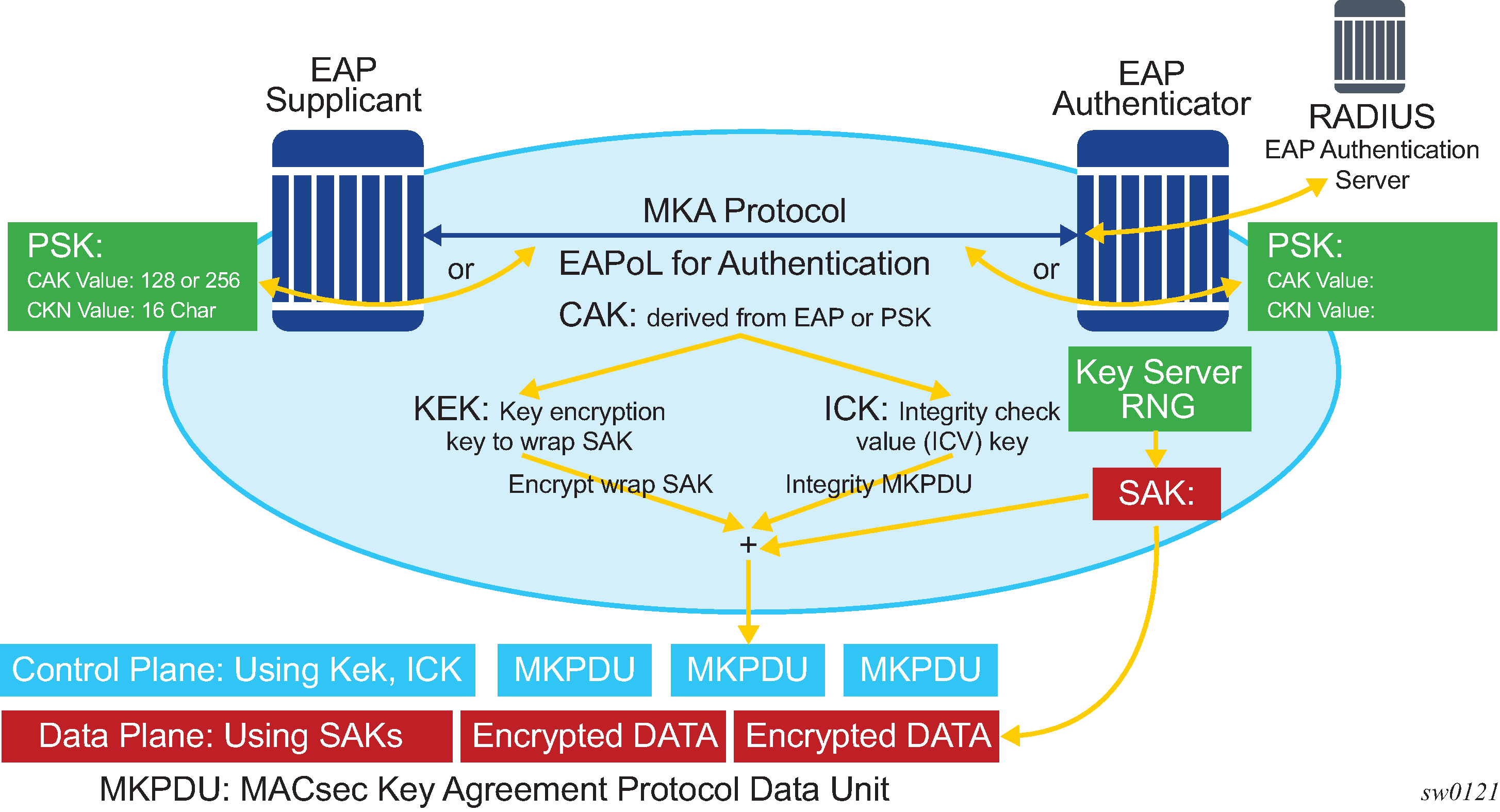
The following figure shows MACsec generating the CAK.
The node initially needs to secure control-plane communication to distribute SAKs between two or more members of a CA domain.
The CAK is used to secure the control plane. The following main methods are used to generate the CAK:
EAPoL (SR OS does not support EAPoL)
pre-shared key (CAK and CKN values are configured manually using the CLI). The following CAK and CKN rules apply:
CAK has 32 hexadecimal characters for a 128-bit key and 64 hexadecimal characters for a 256-bit key, depending on which algorithm is used for control plane encryption (for example, aes-128-cmac or aes-256-cmac).
CKN has 32 octets char (64 hex) and is the connectivity association key name, which identifies the CAK. This allows each MKA participant to select which CAK to use to process a received MKPDU. MKA places no restriction on the format of the CKN, except that it must comprise an integral number of octets, between 1 and 32 (inclusive), and that all potential members of the CA use the same CKN.
CKN and CAK must match on peers to create a MACsec secure CA.
The following figure shows the MACsec control plane authentication and encryption.
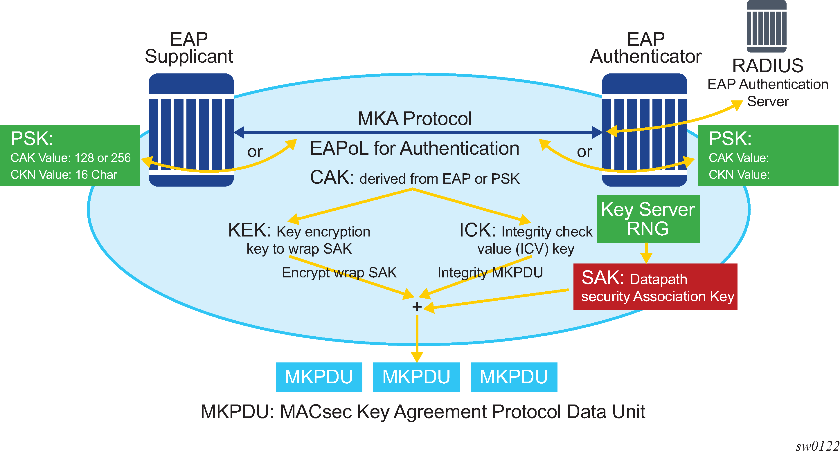
A generated CAK can obtain the following additional keys:
-
Key Encryption Key (KEK) – key used to wrap and encrypt the SAKs
-
Integrity Connection Value (ICV) Key (ICK) – key used for an integrity check of each MKPDU sent between two CAs
The key server then creates a SAK, which is shared with the CAs of the security domain, and that SAK secures all data traffic traversing the link. The key server continues to periodically create and share a randomly created SAK over the point-to-point link for as long as MACsec is enabled.
The SAK is encrypted via the AES-CMAC, using the KEK as the encryption key, and ICK as the integration key.
SAK rollover
SR OS regenerates the SAK after the following events:
when a new host has joined the CA domain and MKA hellos are received from this host
when the sliding window is reaching the end of its 32-bit or 64-bit length
when a new preshared key (PSK) is configured and a rollover of PSK is executed
MKA
Each MACsec peer operates the MKA. Each node can operate multiple MKAs, based on the number of CAs the node belongs to. Each MKA instance is protected by a distinct secure CAK, which allows each PAE to ensure that information for an MKA instance is accepted only from other peers that also possess that CAK, which identifies the peers as members or potential members of the same CA. See MACsec static CAK for information about the CAK identification process performed via CKN.
MKA PDU generation
The following table describes the MKA PDUs generated for different traffic encapsulation matches.
| Configuration | Configuration example (<s-tag>.<c-tag>) | MKA packet generation | Traffic pattern match/behavior |
|---|---|---|---|
|
All-encap |
MD-CLI |
untagged MKA packet |
Matches all traffic on the port, including untagged, single-tag, and
double-tag. Default behavior; only available behavior in releases before 16.0. |
|
UN-TAG |
MD-CLI |
untagged MKA packet |
Matches only untagged traffic on port |
|
802.1Q single S‑TAG (specific S‑TAG) |
MD-CLI |
MKA packet generated with S-TAG=1 |
Matches only single-tag traffic on port with tag ID of 1 |
|
802.1Q single S‑TAG (any S‑TAG) |
MD-CLI |
untagged MKA packet |
Matches any dot1q single-tag traffic on port |
|
802.1ad double tag (both tag have specific TAGs) |
MD-CLI |
MKA packet generated with S-tag=1 and C-TAG=1 |
Matches only double-tag traffic on port with service tag of 1 and customer tag of 1 |
|
802.1ad double tag (specific S‑TAG, any C‑TAG) |
MD-CLI |
MKA packet generated with S-TAG=1 |
Matches only double-tag traffic on port with service tag of 1 and customer tag of any |
|
802.1ad double tag (any S‑TAG, any C‑TAG) |
MD-CLI |
untagged MKA packet |
Matches any double-tag traffic on port |
Tags in clear behavior by traffic encapsulation type
Tags in clear behavior describes how single or double tags in clear configuration under a connectivity association affect different traffic flow encryptions.
By default, all tags are encrypted in CA. An MKA can be generated without any tags (untagged), but the data being matched can be based on dot1q or QinQ.
| Configuration | Traffic pattern match/behavior | Sub-port CA configuration: no tag in cleartext | Sub-port CA configuration: single tag in cleartext | Sub-port CA configuration: double tag in cleartext |
|---|---|---|---|---|
PORT All-encap |
Matches all traffic on port, including untagged, single-tag, double-tag traffic (Release 15.0 default behavior) |
MKA PDU: untagged Untagged traffic: encrypted Single-tag traffic: encrypted, no tag in clear Double-tag traffic: encrypted, no tag in clear |
MKA PDU: untagged Untagged traffic: in clear Single-tag traffic: encrypted, single-tag in clear Double-tag traffic: encrypted, single-tag in clear |
MKA PDU: untagged Untagged traffic: in clear Single-tag traffic: in clear Double-tag traffic: encrypted, double-tag in clear |
untagged |
Matches only untagged traffic on port |
MKA PDU: untagged Untagged traffic: encrypted Single-tag traffic: not matched by this MACsec policy Double-tag traffic: not matched by this MACsec policy |
N/A |
N/A |
802.1Q single tag (specific tag) |
Matches only single-tag traffic on port with the configured tag value |
MKA PDU: untagged Untagged traffic: not matched by this MACsec policy Single-tag traffic: tag is encrypted Double-tag traffic: not matched by this MACsec policy |
MKA PDU: same tag as the one configured under encap-match Untagged traffic: not matched by this MACsec policy Single-tag traffic: tag is in clear Double-tag traffic: not matched by this MACsec policy |
N/A |
802.1Q single tag (any tag) |
Matches all single-tag traffic on port |
MKA PDU: untagged Untagged traffic: not matched by this MACsec policy Single-tag traffic: encrypted Double-tag traffic: not matched by this MACsec policy |
MKA PDU: untagged Untagged traffic: not matched by this MACsec policy Single-tag traffic: encrypted with single tag in clear Double-tag traffic: not matched by this MACsec policy |
N/A |
802.1ad double tag (both tag have specific values) |
Matches only double-tag traffic on port with both configured tag values |
MKA PDU: untagged Untagged traffic: not matched by this MACsec policy Single-tag traffic: not matched by this MACsec policy Double-tag traffic matching both configured tags: encrypted, no tag in clear |
MKA PDU: single tag, equal to S-TAG Untagged traffic: not matched by this MACsec policy Single-tag traffic: not matched by this MACsec policy Double-tag traffic matching both configured tags: single S-TAG in clear |
MKA PDU: double tag, equal to the values configured under the encap-match Untagged traffic: not matched by this MACsec policy Single-tag traffic: not matched by this MACsec policy Double-tag traffic matching both configured tags: encrypted, both tags in clear |
802.1ad double tag (specific S-TAG, any C-TAG) |
Matches only double-tag traffic on port with the configured S-TAG |
MKA PDU: untagged Untagged traffic: not matched by this MACsec policy Single-tag traffic: not matched by this MACsec policy Double-tag traffic matching the configured S-TAG: encrypted, no tag in clear |
MKA PDU: single tag, equal to S-TAG Untagged traffic: not matched by this MACsec policy Single-tag traffic: not matched by this MACsec policy Double-tag traffic matching the configured S-TAG: S-TAG tag in clear |
MKA PDU: single tag, equal to S-TAG Untagged traffic: not matched by this MACsec policy Single-tag traffic: not matched by this MACsec policy Double-tag traffic matching the configured S-TAG: both tags in clear |
802.1ad double tag (any S-TAG, any C-TAG |
Matches all double-tag traffic on port |
MKA PDU: untagged Untagged traffic: not matched by this MACsec policy Single-tag traffic: not matched by this MACsec policy Double-tag traffic: encrypted, no tag in clear |
MKA PDU: untagged Untagged traffic: not matched by this MACsec policy Single-tag traffic: not matched by this MACsec policy Double-tag traffic: S-TAG tag in clear |
MKA PDU: untagged Untagged traffic: not matched by this MACsec policy Single-tag traffic: not matched by this MACsec policy Double-tag traffic: both tags in clear |
PSK
MKA protects the integrity of MKPDUs and secures the SAK using keys that are derived from the CAK. The CAK and CKN are configured as part of a PSK entry under the static CAK configuration.
SR OS supports the following methods for configuring a static CAK:
-
active PSK index
Two PSK entries identified by indexes 1 and 2. The active PSK selects the PSK entry that is used for the MKA session. This method uses a single MKA session. Each time the active PSK is rotated, the CKN and the derived keys are replaced for the same MKA session. A new PSK does not instantiate a new MKA session.
-
a keychain where the SR OS keychain infrastructure is used
A keychain contains multiple key entries, where each key entry corresponds to a PSK that is active from its configured begin time up to the next key entry's begin time plus a configurable tolerance. With this method, every key entry rotation (PSK rotation) instantiates a new MKA session that is named by the CKN and secured by keys derived from the CAK configured in the key entry (PSK). The previous MKA session bound to the old key entry is deleted when its key entry tolerance expires. See Keychain interaction with MACsec for more information about MACsec usage with keychains.
Active PSK configuration
With an active PSK, an MKA participant can support one or more PSKs. These PSKs secure the same MKA session; PSK rotation does not instantiate a new MKA session.
A PSK may be created by NSP or entered manually using the CLI.
Each PSK is configured with the following fields:
-
CAK name (CKN)
-
encryption type
The CKN must be unique per port for the configured sub-ports, and can be used to identify the key in subsequent management operations.
Each static CAK configuration can have two PSK entries for rollover. The active PSK index dictates which CAK is used to derive the keys for encrypting the SAKs and verifying the integrity of the MKPDUs.
NSP provides additional functionality to roll over and configure the PSK. The rollover using NSP can be based on a configured timer.
Keychain
With a keychain, up to 64 PSK entries (keys) can be configured. Each PSK creates a new dedicated MKA session, active for the duration of the key lifetime plus the configured tolerance.
The active PSK and keychain configurations do not operate simultaneously. When a keychain is configured, it takes precedence over the active PSK configuration. When a keychain is not configured, the active PSK is used. To configure the active PSK or keychain, first administratively disable the CA.
SR OS can use the keychain for MACsec PSK rotation. A new MACsec container holds the keychain’s key entries, where the PSK, CAK, and CKN values can be configured as hexadecimal characters. A keychain contains multiple key entries. Each entry is activated at its begin time; it remains valid up to the begin time of the next key entry, plus its own tolerance time.
A MACsec keychain supports the same ciphers as an active PSK. The aes-128-cmac and aes-256-cmac ciphers can be configured per keychain key entry for MACsec.
The following MACsec container is used to configure the MACsec keychain entries:
-
MD-CLI
configure system security keychains keychain macsec -
classic CLI
configure system security keychain macsec
When a keychain is configured with a MACsec key entry, other key entry types, such as bidirectional, received, or send, can no longer be added to the keychain. All MACsec key entries in the keychain must be removed to repurpose it for other key entry types.
Conversely, when a keychain is configured with any bidirectional, received, or send key entries, MACsec key entries can no longer be added. All existing key entries in the keychain must be removed to repurpose it for MACsec use.
Only a keychain with at least one MACsec key entry can be assigned to a MACsec static CAK. When a keychain is assigned to a MACsec static CAK, deleting the MACsec key entry is rejected.
Transitioning from an active PSK to a keychain
For greenfield deployments, the user must choose between an "active PSK" and a "keychain" method for PSK rotation, as the two methods behave differently.
Users can upgrade from an active PSK implementation to a keychain. The following procedures are recommended when upgrading:
-
To configure either a keychain or an active PSK, the CA must be administratively disabled first.
-
Add the keychain after the CA is administratively disabled, and then administratively enable the CA.
-
When the CA's static CAK contains a keychain, the keychain takes precedence over an active PSK configuration under the static CAK, even if the keychain key entries are not active or the MKA sessions for the keychain are not operationally up. That is, only one method is used at a time, with a keychain having precedence over an active PSK when configured.
-
To remove the keychain, the CA must be administratively disabled again.
Keychain interaction with MACsec
In other applications, the tolerance of a keychain key entry can be configured as 0, with a default tolerance of 300 seconds. The MACsec application requires a minimum tolerance value of 20 seconds; a 0 tolerance value is rejected if the key entry is a MACsec entry.
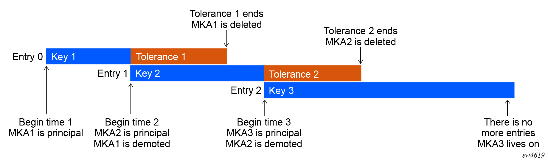
The MKA instance created by the first active key entry serves as the principal session from its begin time and remains functional until the end of its tolerance period. When the next key entry becomes active at its begin time, a new MKA instance is created. When the new MKA instance becomes operationally up, it becomes the principal session, and the MKA instance created by the first key entry becomes the backup session until its tolerance timer expires. If the new MKA session does not become operationally up by the time the tolerance of the first key entry expires, the MACsec sub-port becomes operationally down because neither the first nor second key entry has an operational MKA instance.
Tolerance in a keychain
On SR OS, the default tolerance value for a MACsec key is 300 seconds (5 minutes). A tolerance value below 20 seconds is rejected.
The following figure shows an example of tolerance with three key entries.
Backup key
The following figure shows an example where key 0 is a backup key with the tolerance set to forever.
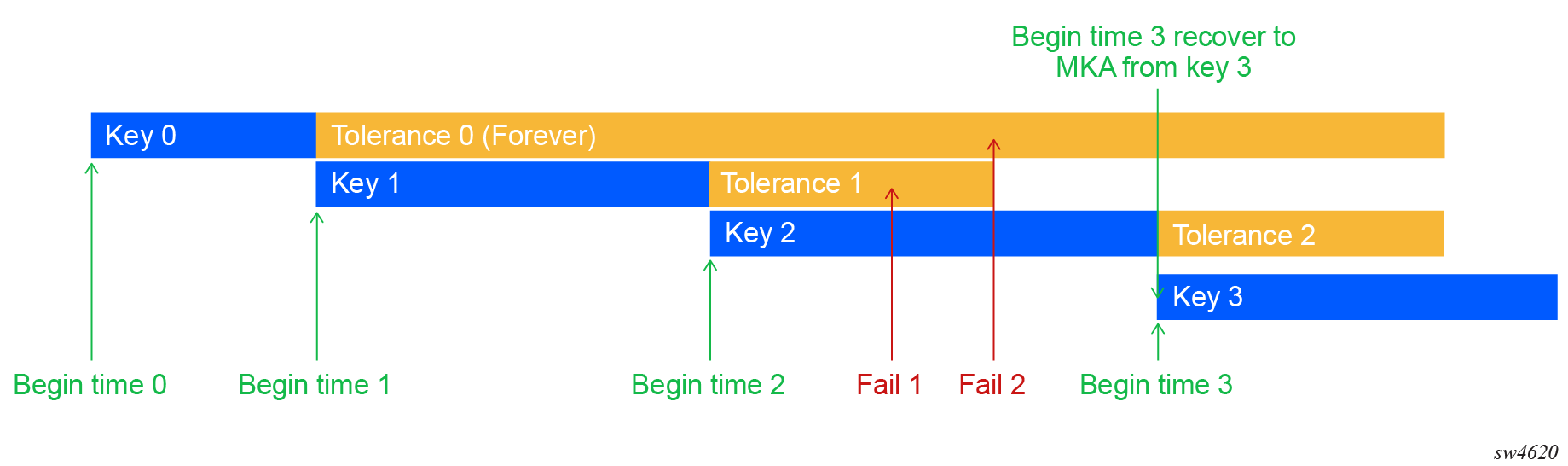
In Backup key with the tolerance set to forever, the following also applies:
-
The MKA session for Key 0 can live forever using the tolerance set to forever. This means the MKA session for Key 0 exchanges MKA hellos, but it is not the principal session.
-
Only Key 0 is intended to be a long-lived backup key. To effectively use it as a backup key, its tolerance should be set to forever. However, no restrictions are placed on its begin time and tolerance values to allow flexibility in use cases.
Note: If a backup key is not required, it is recommended not to configure Key 0. -
If the MKA session of Key 1 or Key 2 fails, the MKA session of Key 0 takes over as the principal MKA session.
- At Fail 1 point of Key 2, the fallback is Key 1 because its tolerance has not expired.
-
At Fail point 2 of Key 2, the fallback key is the Key 0 backup key entry.
-
With the exception of Key 0, any configuration that results in more than two overlapping active keys (and therefore MKA sessions) is rejected.
- If at the end of Key 1, Tolerance 1 and Key 2 have not established an MKA session (for example, Key 2 has a mismatch in its CKN between the peers), the Key 0 MKA session takes over and becomes the principal MKA session. The switch from Key 1 to Key 0 after the Key 1 tolerance expires is seamless.
Unique CKN per port
MACsec requires a unique CKN for each port. Identical CKNs are not allowed for consecutive keychain entries. Identical CKNs can be programmed on multiple keychains that are used for multiple subports on a MACsec port.
For example:
-
Port 1/1/1, subport 1 is using keychain 1 and has one entry with CKN “1234”
-
Port 1/1/1, subport 2 is using keychain 2 and also has one entry with CKN “1234”
-
Port 1/1/1, subport 3 is using static CAK PSK 1 that has CKN “1234”
MKA Hello timer
MKA uses a member identifier (MI) for each node in the CA domain.
A participant proves liveness to each of its peers by including its MI, together with an acceptably recent message number (MN), in an MKPDU.
To avoid a new participant having to respond to each MKPDU from each partner as it is received, or trying to delay its reply until it is likely that MI MN tuples have been received from all potential partners, each participant maintains and advertises both of the following:
-
live peers list
This list includes all the peers that have included the participant MI and a recent MN in a recent MKPDU.
-
potential peers list
This list includes all the other peers that have transmitted an MKPDU that was directly received by the participant or that were included in the live peers list of an MKPDU transmitted by a peer that has proved liveness.
Peers are removed from each list when an interval of between MKA Life Time and MKA Life Time plus MKA Hello Time has elapsed since the participant's recent MN was transmitted. This time is sufficient to ensure that two or more MKPDUs have been lost or delayed prior to the incorrect removal of a live peer.
The following table describes the MKA participant timer values used on SR OS.
| Timer use | Timeout (option) | Timeout (option) |
|---|---|---|
Per participant periodic transmission, initialized for each transmission on expiry |
MKA Hello Time or MKA Bounded Hello Time |
2.0 0.5 |
Per peer lifetime, initialized when adding to or refreshing the potential peers list or live peers list; expiry causes removal from the list |
MKA Life Time |
6.0 |
Participant lifetime, initialized when participant is created or following the receipt of an MKPDU; expiry causes the deletion of the participant |
||
Delay after last distributing a SAK, before the Key Server distributes a fresh SAK following a change in the live peer list while the potential peer list is still not empty |
MACsec Capability, Desire, and encryption offset
802.1x-2010 had identified the following fields in the MKA PDU:
MACsec Capability
Desire
MACsec Capability signals whether MACsec is capable of integrity and confidentiality. The following table describes the basic settings for MACsec Capability.
| Setting | Description |
|---|---|
0 |
MACsec is not implemented |
1 |
Integrity without confidentiality |
2 |
The following are supported:
|
31 |
The following are supported:
|
An encryption offset of 0, 30, or 50 starts from the byte after the SecTAG (802.1ae header). Ideally, the encryption offset should be configured for IPv4 (offset 30) and IPv6 (offset 50) to leave the IP header in cleartext. This allows routers and switches to use the IP header for LAG or ECMP hashing.
Key server
The participants in an MKA instance agree on a Key Server and are responsible for the following:
deciding on the use of MACsec
cipher suite selection
SAK generation and distribution
SA assignment
identifying the CA when two or more CAs merge
Each participant in an MKA instance uses the Key Server Priority (an 8-bit integer) encoded in each MKPDU to agree on the Key Server. Each participant selects the live participant advertising the highest priority as its Key Server whenever the live peers list changes, provided that the highest-priority participant has not selected another as its Key Server or is unwilling to act as the Key Server. If a Key Server cannot be selected, SAKs are not distributed. In the event of a tie for the highest-priority Key Server, the member with the highest-priority SCI is chosen. For consistency with other uses of the SCI MAC address component as a priority, numerically lower values of the Key Server Priority and SCI are afforded the highest priority.
SA limits and network design
Each MACsec device supports 64 TX-SAs and 64 RX-SAs. An SA is the key to encrypt or decrypt the data.
In accordance with the IEEE 802.1AE standard, each SecY contains an SC, which is a unidirectional concept; for example, Rx-SC or Tx-SC. Each SC contains at least one SA for encryption on Tx-SC and decryption on Rx-SC. For extra security, each SC should be able to roll over the SA. The system allocates resources for two SAs on each SC for rollover purposes, as defined in the standard.
Each MACsec phy, referred to as a MACsec security zone, supports 64Tx-SAs and 64 RX-SAs. Assuming two SAs per SC for SA rollover, each security zone supports 32 RX-SC and 32 TX-SC.
The following table describes the port mapping to security zones.
| MDA | Ports in security zone 1 | Ports in security zone 2 | Ports in security zone 3 | SA limit per security zone |
|---|---|---|---|---|
|
12-port SFP+/SFP MDA-e |
Ports 1, 2, 3, 4 |
Ports 5, 6, 7, 8 |
Ports 9, 10, 11, 12 |
Rx-SA = 64 Tx-SA = 64 |
P2P (switch-to-switch) topology
In a point-to-point (P2P) topology, each router needs a single security zone and a single Tx-SC for encryption, and a single Rx-SC for decryption. Each SC has two SAs. In total, for P2P topology, four SAs are needed: two RxSAs for RxSC1 and two TXSAs for TxSC1. The following figure shows the P2P topology.
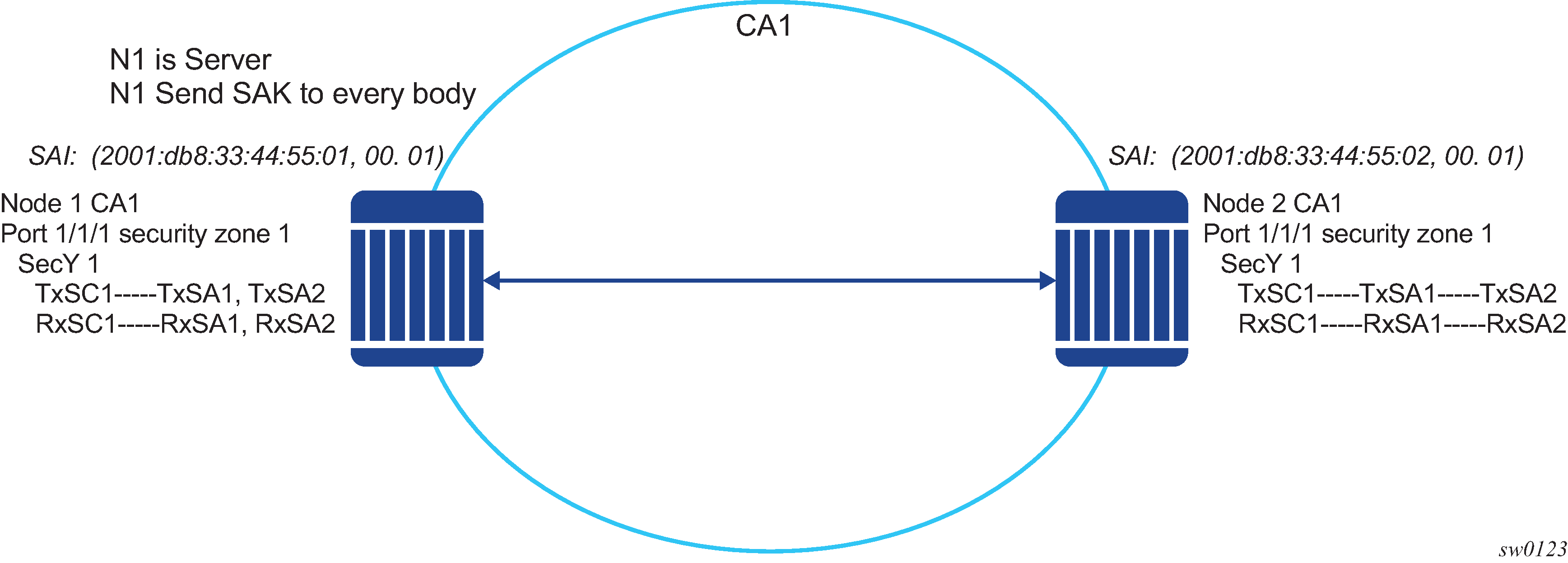
P2MP (switch-to-switch) topology
In a multipoint topology with N nodes, each node needs a single TxSC and N RxSC, one for each of the peers. For example, 64 maximum RX-SAs per security zone translates to 32 Rx-SCs, which breaks down to only 32 peers (only 33 nodes in the multipoint topology per security zone, where each node has one TxSC and 32 RxSC).
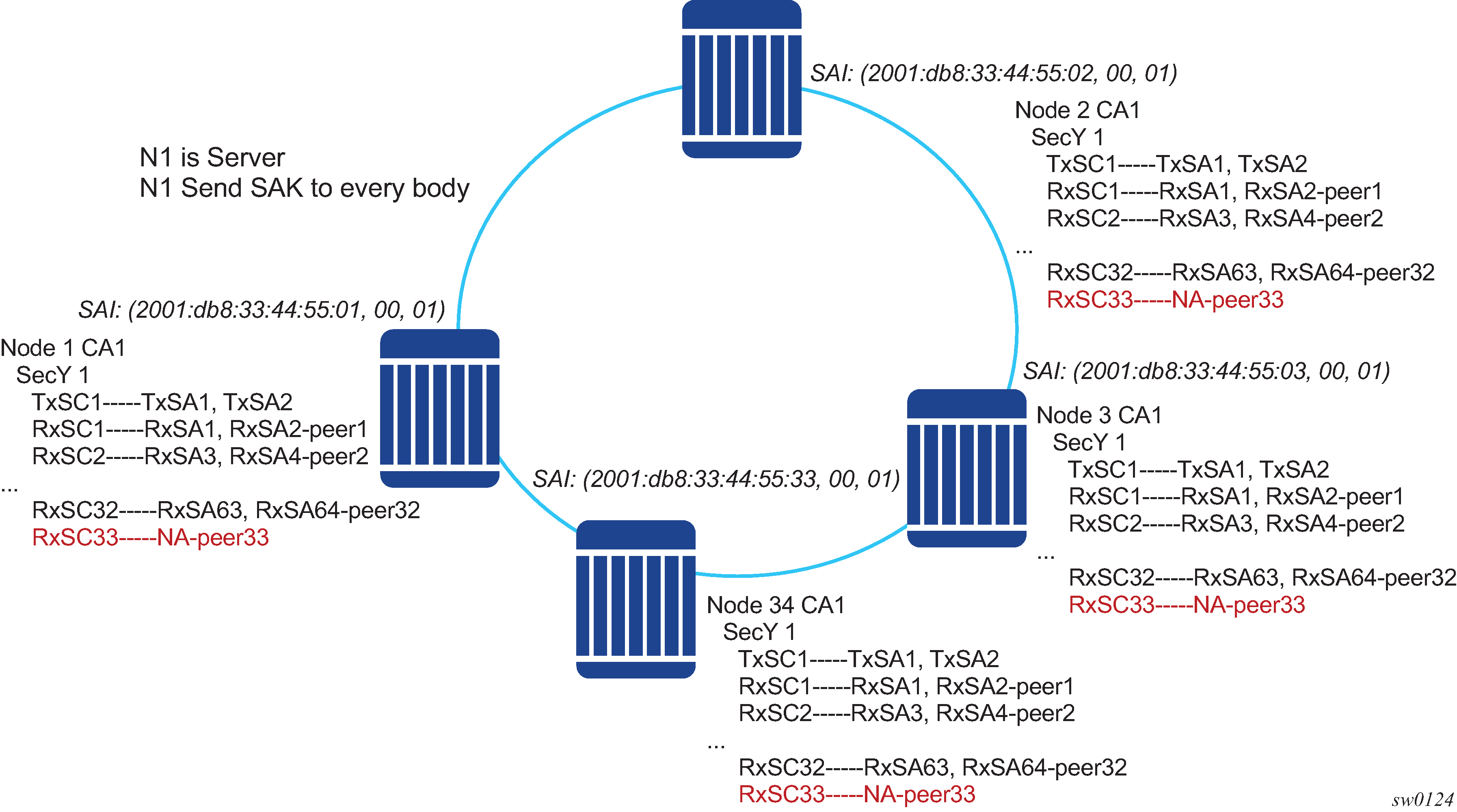
In the preceding figure, when the 34th node joins the multipoint topology, the other 33 nodes that are already part of this domain do not have SAs to create an RxSC for the 34th node. However, the 34th node has a TxSC and accepts 32 peers. The 34th node starts transmitting and encrypting the PDUs based on its TxSC. However, because the other nodes do not have an SC for this SAI, they drop all Rx PDUs.
SA exhaustion behavior
SA limits and network design describes that a security zone has 64 RxSAs and 64 TxSAs. Two RxSAs are used for each RxSC for rollover purposes, and two TxSAs are used for TxSC for rollover purposes. This translates to 32 peers per security zone.
Under each port, users can configure the maximum number of peers allowed on that port.
- MD-CLI
configure port ethernet dot1x macsec sub-port max-peers - classic
CLI
configure port ethernet dot1x macsec sub-port max-peer
Clear tag mode
In most Layer 2 networks, MAC forwarding is performed via the destination MAC address. The 802.1AE standard dictates that any field after the source and destination MAC address and after the SecTAG must be encrypted. This includes the 802.1Q tags. In some VLAN switching networks, it may be necessary to leave the 802.1Q tag in cleartext.
SR OS supports configuring 802.1Q tags in cleartext by placing the 802.1Q tag before the SecTAG, or in encrypted text by placing it after the SecTAG.
The following table lists the MACsec encryption of 802.1Q tags when clear-tag-mode is configured on the SR OS.
| Unencrypted format | clear-tag-mode configuration | Pre-encryption (Tx) | Pre-decryption (Rx) |
|---|---|---|---|
Single tag (dot1q) |
Single-tag |
DA, SA, TPID, VID, Etype |
DA, SA, TPID, VID, SecTAG |
Single tag (dot1q) |
Double-tag |
DA, SA, TPID, VID, Etype |
DA, SA, TPID, VID, SecTAG |
Double tag (QinQ) |
Single-tag |
DA, SA, TPID1, VID1, IPID2, VID2, Etype |
DA, SA, TPID1, VID1, SecTAG |
Double tag (QinQ) |
Double-tag |
DA, SA, TPID1, VID1, IPID2, VID2, Etype |
DA, SA, TPID1, VID1, IPID2, VID2, SecTAG |
802.1x tunneling and multihop MACsec
MACsec is an Ethernet packet and, as with any other Ethernet packet, can be forwarded through multiple switches via Layer 2 forwarding. Packet encryption and decryption is performed via 802.1x (MKA) capable ports.
To ensure that MKA is not terminated on any intermediate switch or router, the user can enable 802.1x tunneling on the corresponding port.
The following example shows how to check if tunneling is enabled.
MD-CLI
[ex:/configure port 1/1/12 ethernet dot1x]
A:admin@node-2# info
    tunneling true
classic CLI
A:node-2>config>port>ethernet>dot1x# info
----------------------------------------------
      tunneling
By enabling tunneling, the 802.1x MKA packets transit the port without being terminated. Therefore, MKA negotiation does not occur on a port that has 802.1x tunneling enabled.
EAPoL destination address
The MKA packets are transported over EAPoL with a multicast destination MAC address. If it is required for the MKA have a point-to-point connection to a peer node over a Layer 2 multihop cloud, the EAPoL destination MAC address can be set to the peer MAC address. This forces the MKA to traverse multiple nodes and establish an MKA session with the specific peer.
Mirroring consideration
Mirroring is performed before the MACsec encryption engine. Therefore, if a port is MACsec-enabled and mirrored, all mirrored packets are in cleartext.
Exponential Port Dampening
Exponential Port Dampening (EPD) provides the ability to automatically block a port from reuse for a period of time after physical link-down and physical link-up events. If a series of down-up events occur close together, EPD keeps the port’s operational state down for a longer period than if only one down-up event has occurred. The router avoids using that port if external events are causing the link state to fluctuate. The more events that occur, the longer the port is kept down and avoided by the routing protocols.
EPD behavior uses a fixed penalty amount per link-down event and a half-life decay equation to reduce these penalties over time. The following equation defines exponential decay:
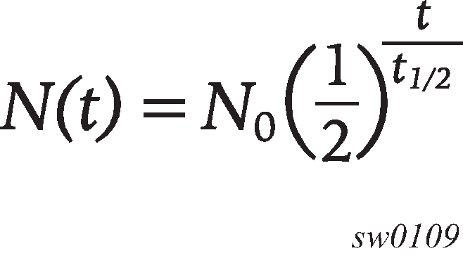
where:
N(t) is the quantity that still remains after a time t
N0 is the initial quantity
t½ is the half-life
In dampening, N0 refers to the starting penalties from the last link-down event. The quantity N(t) refers to the decayed penalties at a specific time, and is calculated starting from the last link-down event (that is, from the time when N0 last changed).
This equation can also be used on a periodic basis by updating the initial quantity value N0 each period and then computing the new penalty over the period (t).
The following figure shows an example usage of the EDP feature.
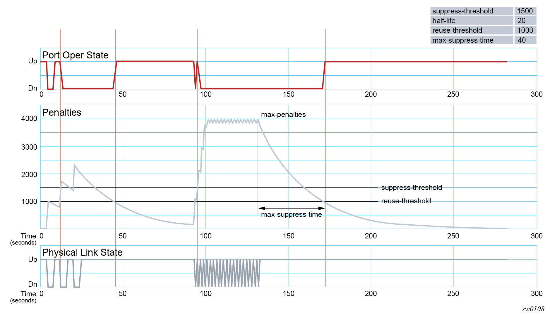
At time (t = 0) in the preceding figure, the initial condition has the link up, the accumulated penalties are zero, the dampening state is idle, and the port operational state is up. The following series of events and actions occur.
t = 5: link-down event
the accumulated penalties are incremented by 1000
the accumulated penalties now equal 1000, which is less than the suppress threshold (of 1500), so the dampening state is idle
because the dampening state is idle, link-down is passed to the upper layer
link-down triggers the port operational state to down
t = 9: link-up event
the accumulated penalties equal 869, which is less than the suppress threshold, so the dampening state remains as idle
because the dampening state is idle, link-up is passed to the upper layer
link-up triggers the port operational state to up
t = 13: link-down event
the accumulated penalties are incremented by 1000
the accumulated penalties now equal 1755, which is greater than the suppress threshold, so the dampening state is changed to active
because the dampening state just transitioned to active, link-down is passed to the upper layer
link-down triggers the port operational state to down
t = 17: link-up event
the accumulated penalties equal 1527, which is above the reuse threshold (of 1000) and greater than the suppress threshold, so the dampening state remains as active
because the dampening state is active, link-up is not passed to the upper layer
the port operational state remains down
t = 21: link-down event
the accumulated penalties are incremented by 1000
the accumulated penalties now equal 2327, which is above the reuse threshold, so the dampening state remains as active
because the dampening state is active, link-down is not passed to the upper layer
the port operational state remains down
t = 25: link-up event
the accumulated penalties equal 2024, which is above the reuse threshold, so dampening state remains as active
because the dampening state is active, link-up is not passed to the upper layer
the port operational state remains down
t = 46: accumulated penalties drop below the reuse threshold
the accumulated penalties drop below the reuse threshold, so the dampening state changes to idle
because the dampening state is idle and the current link state is up, link-up is passed to the upper layer
the port operational state changes to up
t = 94 to 133: link-down and link-up events every second
similar to previous events, the accumulated penalties increment on every link-down event
the dampening state transitions to active at t = 96, and link state events are not sent to the upper layer after that time
the upper layer keeps the port operational state down after t = 96
the accumulated penalties increment to a maximum of 4000
t = 133: final link event of link-up
the accumulated penalties equal 3863
the dampening state remains active and link state events are not sent to the upper layer
the upper layer keeps the port operational state down
t = 172: accumulated penalties drop below the reuse threshold
the accumulated penalties drop below the reuse threshold, so the dampening state changes to idle
because the dampening state is idle and the current link state is up, link-up is passed to the upper layer
the port operational state changes to up
Network synchronization on ports
Network synchronization on T1/E1 ports
Each T1/E1 port can be independently configured for loop-timing (recovered from an Rx line) or node-timing (recovered from the system synchronization unit (SSU) in the active control processing module (CPM)).
A T1/E1 port can be configured to be a timing source for the node.
Ethernet port down-when-looped
Newly provisioned circuits are often looped back using a physical loopback cable for testing and to ensure the ports meet the SLA. If loopbacks are not cleared, or physically removed, by the operator when the testing is completed, they can adversely affect the performance of all other SDPs and customer interfaces (SAPs). This is especially problematic for point-to-multipoint services such as VPLS, because Ethernet does not support TTL, which is essential in terminating loops.
The down-when-looped feature is used on the 7705 SAR Gen 2 to detect loops within the network and to ensure the continued operation of other ports. When this feature is activated, a keepalive loop PDU is periodically transmitted toward the network. The Ethernet port then listens for returning keepalive loop PDUs. In unicast mode, a loop is detected if any received PDUs have an Ethertype value of 9000, which indicates a loopback (Configuration Test Protocol), and the source and destination MAC addresses are identical to the MAC address of the Ethernet port. In broadcast mode, a loop is detected if any received PDUs have an Ethertype value of 9000 and the source MAC address matches the MAC address of the Ethernet port, and the destination MAC address matches the broadcast MAC address. When a loop is detected, the Ethernet port is immediately brought down.
EFM OAM and the down-when-looped feature cannot be enabled on the same port.
Forward Error Correction
Users can use Forward Error Correction (FEC) on some ports to improve either the transmission reliability or reach, or both. FEC must always be used on some interface types while it is optional for other interface types. Also, some interface types allow more than one type of FEC. No matter what the setting of the FEC attributes, the transmitter and the receiver must have the same configuration, or the link will not work. The setting of FEC on a specific port is dependent on the interface type and the specific optical transceiver in use.
For coherent optics, the FEC (host and media) do not need to be configured and are automatically inherited and enabled based on the specific module and configured coherent mode of operation.