Cellular MDA and ports
In this chapter
This chapter describes the cellular MDA and cellular ports. Topics include:
For more information about using the cellular MDA and ports for establishing IP/MPLS service, see the following topics in the 7705 SAR-Hm and SAR-Hmc Main Configuration Guide:
PDN router interfaces
Services over the cellular PDN interface
Dedicated bearers
Overview
The cellular MDA supports 4G LTE and 3G connectivity, depending on the radio module installed in the node. See the SAR-Hm and SAR-Hmc Chassis Installation Guide for information about the types of supported modules.
Each node supports a single cellular MDA. Each cellular MDA supports two cellular ports, one for each SIM that can be configured on the node. Each cellular port has its own PDN router interface. A PDN router interface is a network-facing interface that is used to route traffic to and from the node over a cellular network, providing WAN connectivity over the cellular port.
Prerequisites and required configurations
Before configuring the cellular MDA and cellular ports, the following prerequisites must be considered.
Depending on the radio module selected, 4G LTE/3G network coverage is required where the node is to be physically installed.
The operator must subscribe to a service plan with a wireless service provider. For private cellular networks, the operator must procure a SIM that allows the node to connect to the private cellular network being deployed. If dual SIM functionality is required, the operator must subscribe to a second service plan with another wireless provider and procure a second SIM.
The radio firmware shipped with the node is a generic firmware version. Some service providers require a specific radio firmware version to run on the node, depending on the radio variant used on the node and the wireless service provider being connected to; in this case, the firmware on the node must be updated to the correct version. See the 7705 SAR-Hm and SAR-Hmc Software Release Notes for details about updating the radio firmware to the correct version. If dual SIM functionality is enabled, the firmware associated with the second wireless service provider must be updated for the associated SIM.
The SIM or SIMs must be physically installed before powering up the router and configuring the cellular MDA and cellular ports.
For a typical GSM profile, and if required by the service plan, the following information must be obtained from the service provider: Access Point Name (APN), username, and password. For dual SIM deployments, obtain the GSM profile information for each SIM.
When the prerequisites have been met, the following configurations are required.
A cellular port interface must be configured for each installed SIM.
The required SIMs must be configured under the cellular MDA.
The following CLI syntax shows an example of the required cellular MDA and cellular port parameters:
*A:Dut# configure card 1 mda 1 cellular sim 1
*A:Dut>config>card>mda>cellular>sim# pin
Enter PIN: xxxx
Re-enter PIN: xxxx
*A:Dut>config>>card>mda>cellular>sim# exit
*A:Dut# configure port 1/1/1 cellular pdn
*A:Dut>config>port>cellular>pdn# pdn-profile 1
*A:Dut>config>port>cellular>pdn# exit
*A:Dut#
A cellular system PDN profile must be created and the corresponding APN, GSM parameters (such as username, password, and authentication), and protocol must be configured for each installed SIM. For an example of the CLI syntax required for the PDN profile configuration, see PDN profile.
A PDN router interface must be created for each cellular port to enable services over the cellular port; for information, see "PDN router interfaces" in the 7705 SAR-Hm and SAR-Hmc Main Configuration Guide.
Cellular MDA management
Cellular MDA management activities include the following:
setting SIM control parameters such as specifying the active SIM and the preferred SIM to use after a node reset
specifying the SIM PIN value needed to operate each SIM if SIM security is enabled
specifying failover criteria on each SIM to determine when to automatically switch to the backup SIM when the system is operating in dual SIM mode
configuring optional recovery criteria for cellular ports or BGP sessions that are operationally down, and an associated interval when it is desirable to perform a node reset because of a potential cellular lockup as a result of a modem failure
configuring the maximum transmit power on the 7705 SAR-Hmc for applications that require changes to maximum transmit power. See the 7705 SAR-Hm and SAR-Hmc Software Release Notes for information about applications that require a change to the maximum transmit power.
SIM installation and configuration
Up to two valid SIMs must be procured before configuring the cellular MDA or cellular ports. The SIMs must be inserted into the proper SIM slots before the node is powered up. SIMs cannot be installed when the node is powered on. To run the Automatic Discovery Protocol (ADP-Hm) on the node, a SIM must be inserted into slot 1; otherwise, ADP-Hm will not function. For more information about ADP-Hm, see "Basic system configuration" in the 7705 SAR-Hm and SAR-Hmc Main Configuration Guide.
For information about dual SIM operation, see Dual SIM deployment.
SIM security and security commands
A SIM that is installed on the node can be secured using a personal identification number (PIN). The PIN is a 4- to 8-digit code that is used to control access to information stored on the SIM. The PIN is stored on the SIM and is used to lock the SIM, unlock the SIM, or change the PIN value.
To secure a node, the PIN needs to be set and the SIM must be locked using the PIN. When locked, the SIM cannot be used to access the cellular network unless the PIN is present in the configuration file of the node operating the SIM. If the locked SIM is inserted into another node that does not have the correct PIN configured for the SIM, the SIM will not allow access to the cellular network. If the number of attempts made to access the cellular network using an incorrect PIN exceeds the number of attempts allowed by the SIM, then the SIM will become blocked and will not allow any further attempts to gain access the cellular network.
When a SIM is procured from a carrier, the PIN is either not set or sometimes set to a default value such as 0000 or 1111. When a locked SIM is first installed in the node, the operator must enter the default PIN in the node system configuration twice. When stored in the system configuration, the PIN provides access to the locked SIM, both to read information from the SIM and to grant access to the cellular network.
The PIN can be stored in the system configuration in encrypted form to keep the PIN value secret.
Avoid entering an invalid PIN in the system configuration. If an invalid PIN is saved to the system configuration file, the system will attempt to enter that PIN on the SIM each time the system reboots. This will eventually exhaust the number of available PIN retries for the SIM and make the SIM inoperative until it is unblocked with the personal unblocking key (PUK).
In addition, if multiple attempts are made to either lock or unlock the SIM using an incorrect PIN, the SIM becomes blocked. In both cases, the SIM must be unblocked using the PUK.
The number of allowed attempts to access a SIM depends on the SIM. The ‟PIN retries left” field under the SIM Card heading in the show>port CLI output indicates the number of attempts left before the SIM is blocked and must be unblocked to establish cellular connections.
If the SIM becomes blocked, the operator must enter the personal unblocking key (PUK) in the CLI to unblock the SIM and reset the PIN. The PUK is stored on the SIM and must be acquired from the service provider or administrator.
Many carriers provide unlocked SIMs. If an unlocked SIM is installed in a node, the operator does not need to know the PIN or configure the PIN in order for a cellular port to become operational. For example, during the ADP-Hm process, setting the PIN before attempting to connect to the network is not required.
The default PIN can be changed on the SIM using the tools>perform>mda>cellular>sim>change-pin command. If the default PIN is changed on the SIM, the system configuration must be updated with the new PIN value using the config>card>mda>cellular>sim>pin command.
The commands described below are available for SIM security. All of the SIM security commands are in the tools>perform>mda>cellular>sim context.
lock-sim—this command locks the SIM and enables the PIN verification function on the SIM. A locked SIM verifies the PIN stored in the system configuration for operation. To lock the SIM, the operator must enter the current PIN.
unlock-sim—this command unlocks the SIM and disables the PIN verification function on the SIM. To unlock the SIM, the operator must enter the current PIN.
unblock-sim—this command unblocks a SIM that is currently blocked because too many attempts were made to access the SIM with an incorrect PIN. To unblock the SIM, the operator must enter the PUK for the SIM and then enter a new PIN twice. The lock/unlock state of the SIM does not change when it becomes unblocked.
change-pin—this command allows the operator to change the PIN value on the SIM. The operator must enter the existing PIN and then enter the new PIN twice correctly to change the PIN. The command is shown in the output below.
A:Dut-A# tools perform mda 1/1 cellular sim 1 change-pin
Enter current PIN:
Enter new PIN:
Re-enter new PIN:
When an operator successfully locks a SIM, unblocks a SIM, or changes a SIM PIN, the system updates the PIN value in the system configuration. However, the system does not automatically save the system configuration containing the new PIN. The operator must perform an admin>save command immediately after changing the PIN in order to save the new PIN in the system configuration file and avoid potential service interruptions such as the node becoming unreachable.
If the SIM becomes blocked when setting the PIN remotely using in-band management over a cellular port, the node will be unreachable. Physical access to the node will be required to unblock the SIM.
Cellular band selection
In some deployments, it may be necessary to control which spectrum the cellular interface uses when it is searching for a cellular network to connect to. This can be achieved by configuring a list of cellular bands for each SIM using the command configure>card>mda>cellular>sim>band-list. See the 7705 SAR-Hm and SAR-Hmc Software Release Notes for information about the platforms that support cellular band selection.
The operator creates the band list by specifying the bands that are supported on the MDA. A total of four bands can be configured in the list: up to three LTE bands and one 3G band.
In a dual SIM deployment, a band list can be configured on one or both SIMs.
A SIM switchover causes the MDA to reset. If a band list is configured on the newly active SIM, the reset enables this band list. If the newly active SIM is not configured with a band list, the node uses the bands that are supported by the firmware.
If the list contains bands that are not supported by the firmware for a specific carrier, the node will use only the bands that are supported by the firmware. For example, if the firmware supports bands B2, B5, B7, B13, and B66 but the band-list is configured with bands B2, B42, B48, and B71, the node will only allow B2 to be configured on the MDA because it is the only band on the list that is supported by the firmware.
If none of the bands on the list are supported by the firmware, the node considers the band list to be misconfigured and ignores it. The node reverts to enabling all the bands supported by the firmware. Enabling all the supported bands ensures that the node can connect to the network if further actions are required to manage the node.
The output from the show mda 1/1 command provides information about the operational bands in use and whether the band list was applied or ignored. The command output also displays whether 3G is enabled or disabled.
RSSI threshold alarm
The Received Signal Strength Indicator (RSSI) of the cellular interface can be monitored to detect weak signals on the interface. Monitoring signal strength can be useful for determining the stability of the carrier or private LTE network and whether to log (generate) an RSSI threshold alarm log event or generate an alarm log event and switch carriers, either manually or by automatically switching SIMs in a dual SIM deployment.
The rssi-threshold command is used to set the level at which the received signal is considered weak enough to trigger an alarm log event. If the RSSI falls below the configured threshold, a tmnxCellularRssiAlarm log event is generated. As well, if the threshold is configured as a failover criterion, a SIM switchover occurs in a dual SIM deployment.
The node polls the radio signal strength approximately once per second. If the RSSI falls below the configured rssi-threshold, a timer starts. If the RSSI stays below the threshold for the time specified with the rssi-alarm-wait-time command, the tmnxCellularRssiAlarm log event is generated. This log event is generated only once even if the RSSI remains below the threshold indefinitely. After the tmnxCellularRssiAlarm log event is generated, if the RSSI level rises to the configured rssi-threshold value or higher and remains at that level for the duration of the rssi-alarm-wait-time, the tmnxCellularRssiAlarmClear log event is generated. The operator can monitor the logging frequency to determine whether to manually switch carriers.
The RSSI threshold can be set as a failover criterion in a dual SIM deployment. When the rssi-threshold option is set in the failover-criteria command, if the RSSI signal level falls below the configured RSSI threshold for the configured failure-duration time, the node performs an automatic switchover from the currently active SIM to the other SIM. See Criteria for automatic failover for information about using RSSI as a failover criterion for dual SIMs.
Down-recovery timer and criteria
A down-recovery timer can be set so that if the cellular MDA fails to establish cellular service or if BGP cannot be established on any interface configured in the system, the node will reboot. The down-recovery-interval is configured at the cellular MDA level and is not specific to a particular SIM. The timer can be set when there is a single SIM or two SIMs installed in the node.
The operator can specify the criteria that will cause the node to reboot by configuring the down-recovery-criteria command. The down-recovery-criteria can be set to port or bgp. When set to port, all cellular ports configured on the system are monitored during the down-recovery interval. When set to bgp, all BGP sessions configured on the node are monitored during the down-recovery interval. Both options can be specified concurrently, and the node will use either the cellular port state or BGP session state to declare the operational state of the node as down.
When set, the down-recovery-interval specifies the length of time that the configured down-recovery-criteria are monitored from the moment when either the ports or the BGP sessions are declared operationally down. If the interval is exceeded without any port or BGP sessions going operationally up, the node reboots so that the preferred SIM can try to connect to a cellular network again. As soon as any port or BGP sessions is operationally up, the down-recovery timer stops.
The down-recovery-interval is measured in minutes, with a range of 1 to 240 minutes. Sixty seconds before the timer expires, the node will issue a log event stating that the node will reboot in 60 seconds if the down-recovery condition (based on the configured criteria) is not resolved. This 60-second warning interval can be used for further debugging and diagnostics before the node resets.
Dual SIM deployment
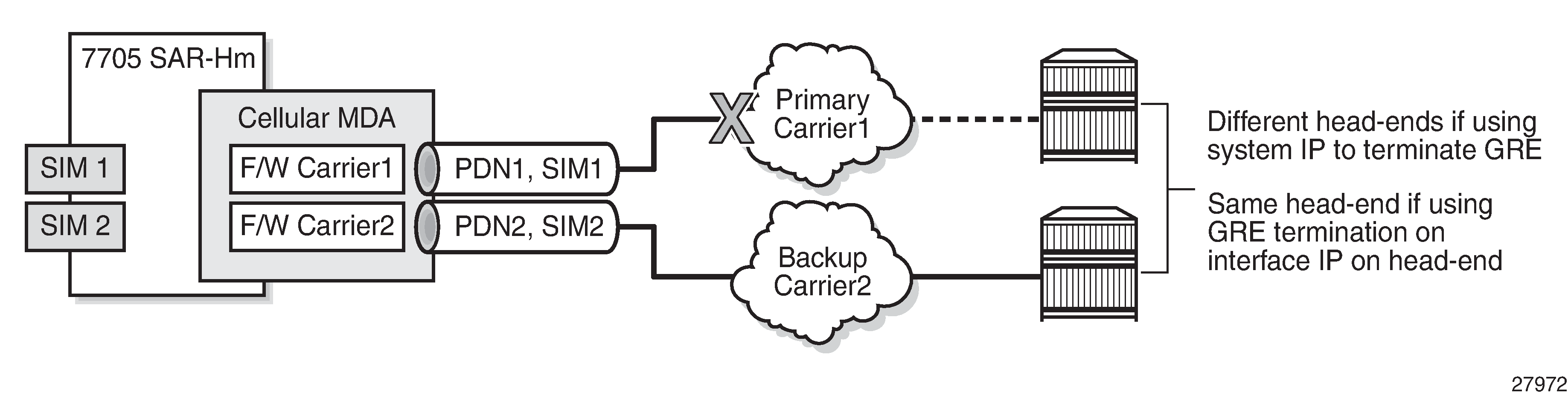
The node supports dual SIM deployment for users who require a redundancy option using two wireless carriers.
With dual SIM deployment, two SIMs are installed in the node, one from each carrier. Only one SIM is active at a time to establish a cellular service WAN connection. The operator choses which SIM is primary and which is secondary or manually selects which SIM to keep active.
Configurable criteria give the operator some control over when it is appropriate for the system to perform a SIM switchover. For example, the BGP operational state associated with the cellular port can be used as a criterion for determining when a SIM switchover should occur. If the BGP operational state is down for a specified interval, a SIM switchover occurs. See Criteria for automatic failover for more information.
A SIM switchover is service-affecting. Operators should perform a SIM switchover only when necessary, as overly frequent switchovers will impact service operation.
Dual SIM operation shows dual SIM operation on a 7705 SAR-Hm.
For information about IP/MPLS services when dual SIM functionality is enabled, see the 7705 SAR-Hm and SAR-Hmc Main Configuration Guide.
Enabling dual SIM operation
To enable dual SIM operation on the node, operators must perform the following tasks.
Procure two SIMs, each for a different cellular network.
If ADP-Hm is required, insert the SIM needed to operate with ADP-Hm into SIM slot 1. For more information about ADP-Hm, see "Basic system configuration" in the 7705 SAR-Hm and SAR-Hmc Main Configuration Guide.
Ensure that each SIM is associated with a unique packet data network (PDN) by configuring a PDN profile and a PDN router interface that will be assigned a unique IP address during the PDN attach process. The PDN profiles and PDN router interfaces must be configured beforehand.
Choose whether the SIMs will be switched manually or use automatic failover. If automatic failover is chosen, the operator must determine the criteria for failover. See Criteria for automatic failover for information.
Active SIM selection
After the two SIMs are installed in the node, the operator chooses which SIM will be active by configuring the active-sim command under the cellular MDA. This command can be configured either with a specific SIM (1 or 2) or with the auto parameter. The default is 1. The configuration of this command determines whether the SIMs are switched manually or use automatic failover.
Manual selection
The operator can manually select the active SIM by configuring a specific SIM as active, either 1 or 2. This configuration makes the selected SIM permanently active.
The active SIM can be manually switched by changing the active-sim setting from 1 to 2 or from 2 to 1.
Changing the active SIM from 1 to 2 or from 2 to 1 is service-affecting. The recovery time after making this change can range from a few seconds to up to a few minutes.
When the system powers up or reboots, it uses the active-sim setting to determine which SIM is the active SIM. If the operator configures the active-sim as 1 but there is no physical SIM in the associated SIM slot, the cellular port remains operationally down. The operator must either install the SIM in the appropriate slot or change the configuration in order to bring the service up.
Automatic failover
An automatic failover occurs when activity switches from one SIM to the other.
Automatic failover is enabled in a dual SIM deployment when the active-sim command is set to auto. In this case, the operator must select the SIM to use as the primary SIM by setting the preferred-sim value. The node uses the preferred-sim setting to determine which SIM to use for a cellular port after a system reset.
If the operator changes the active-sim value from auto to 1 or from auto to 2 and the active SIM is the same as the new configuration, there is no change to service of the active SIM.
Changing the active-sim setting so that the newly active SIM is different from the currently active SIM is service-affecting. The recovery time after making this change could range from a few seconds to up to a few minutes.
If the operator changes the active SIM from 1 to auto or from 2 to auto, there is no service outage. The system keeps the currently active SIM up and does not perform any switchover.
When active-sim is set to auto, the operator can use the tools>perform>mda>cellular>force-sim-switch command to manually force a SIM switch.
The auto parameter can be set if there is only one SIM installed in the system; however, the system keeps the currently active SIM up and does not perform any switchover.
Criteria for automatic failover
When the active-sim command is set to auto, the operator can configure the parameters that will cause an automatic failover to occur. The parameters that serve as criteria for automatic failover are:
-
the cellular port operational state
-
the operational state of all BGP sessions configured on the node
-
the RSSI value
These parameters are configured per SIM and can be different for each SIM. As well, any combination of parameters can be configured for each SIM.
An automatic failover occurs when the conditions are met for any of the configured parameters on the currently active SIM.
Cellular port operational state
The cellular port operational state can be specified as a failover criterion for the currently active SIM. The operational state of cellular port 1/1/1 is used as the failover criterion for SIM 1 and the operational state of cellular port 1/1/2 is used as the failover criterion for SIM 2.
When the cellular port operational state criterion is specified, the system monitors the operational state of the PDN. If the PDN is operationally down for a specified failure-duration, the system performs a SIM failover and attempts to establish cellular service using the other SIM. See Failure duration for more information.
BGP sessions operational state
When the BGP operational state criterion is specified, the system monitors the operational state of all BGP sessions configured on the node. If all the BGP sessions are operationally down for a specified failure-duration, the system performs a SIM failover and attempts to establish cellular service using the other SIM. See Failure duration for more information.
RSSI threshold value
When the RSSI threshold criterion is specified, the system monitors the RSSI signal level of the SIM. If the RSSI level falls below the value set with the rssi-threshold command for a specified failure-duration, the system performs a SIM failover and attempts to establish cellular service using the other SIM. See Failure duration for more information.
Failure duration
When the active-sim command is set to auto and at least one failure criterion is configured, the system uses the length of time configured for the failure-duration to determine when to perform an automatic failover from one SIM to the other.
The failure-duration value is configured per SIM but it applies to all failure criteria. It is not possible to configure one failure duration value for one criterion and another failure duration value for another criterion.
The default value is 5 minutes. The valid range is from 1 minute to 60 minutes.
Cellular port management
A cellular port enables a specific cellular service for an associated SIM. Each cellular port is managed separately per SIM and per PDN.
Cellular port 1/1/1 is associated with SIM 1 and cellular port 1/1/2 is associated with SIM 2.
A cellular port can be shut down by using the port>shutdown command. When a cellular port is shut down, the cellular service for that port is disabled. To enable cellular service for the port, use the port>no shutdown command. See Common configuration commands for more information about the shutdown command.
Use caution when executing the port>shutdown command on a cellular port. Shutting down a cellular port when it is the only means of communication to a remote node over a wireless network may cause permanent loss of connectivity to the node.
Cellular port and its PDN
The node provides a single PDN connection for each cellular port. A cellular port must have an associated PDN router interface in order to allow routed traffic and services over the PDN connection and over the cellular network. For more information about the PDN router interface, see "PDN router interfaces" in the 7705 SAR-Hm and SAR-Hmc Main Configuration Guide.
The node supports the configuration of an access point name (APN) as part of a PDN profile in order to establish the PDN connection. In many cases, the default PDN profile is sufficient to establish a connection. For example, often the only configuration that is necessary to establish a connection is to enable the port using the config>port port-id no shutdown command. However, some carriers may require the user to configure a specific APN before allowing a connection to be established. In those cases, the user must configure a PDN profile and configure the cellular port to use that PDN profile. See PDN profile for more information.
PDN profile
The node uses PDN profiles to establish PDN connections over a cellular port. When the default PDN profile is not sufficient to establish connections, a PDN profile must be created. Manually created PDN profiles contain additional cellular network access configuration items that are not stored on the SIM but that are required in order to establish a PDN connection. PDN profiles can be created, modified, and deleted.
A PDN profile is referenced using a PDN profile ID. When a PDN profile is created at the system level and then configured on a cellular port, it cannot be modified or deleted until it is removed from the cellular port.
PDN profiles are necessary so that CLI or SNMP changes can be made to cellular ports without first having to shut down the ports. For example, when changing the APN information for a cellular port, another PDN profile can be configured with the changed information and assigned to the cellular port. This change will cause the cellular port to connect to the cellular network using the new PDN profile information immediately.
The following items can be configured as part of a PDN profile:
APN—the Access Point Name provided by the service provider to use for the cellular service
authentication—the type of authentication to use for establishing the connection, either Password Authentication Protocol (PAP) or Challenge Handshake Authentication Protocol (CHAP)
description—a description for the PDN profile
password—a password for the PAP or CHAP authentication
protocol—the protocol for the associated PDN interface, either IPv4 or IPv6
username—a username for the PAP or CHAP authentication
The following CLI syntax shows an example of how to configure a PDN profile.
*A:Dut# config>system>cellular# pdn-profile 1
*A:Dut>config>system>cellular>pdn-prof# apn apn1
*A:Dut>config>system>cellular>pdn-prof# authentication pap
*A:Dut>config>system>cellular>pdn-prof# description "PDNprofile1"
*A:Dut>config>system>cellular>pdn-prof# no password
*A:Dut>config>system>cellular>pdn-prof# protocol ipv6
*A:Dut>config>system>cellular>pdn-prof# username waldowaldo
*A:Dut>config>system>cellular>pdn-prof# exit
*A:Dut>config>system>cellular# exit
*A:Du>config>system# exit
*A:Dut>config# exit
*A:Dut#
For more information, see Cellular PDN profile configuration commands.
Default PDN profile
Default PDN profile values lists the settings for the default PDN profile. The default PDN profile is always used when installing a new SIM and running the ADP-Hm process. It can also be used to establish cellular connections that do not require PDN profile configurations. The default PDN profile cannot be modified by the user.
Profile parameter |
Value |
|---|---|
APN |
Blank |
Authentication |
None |
Username |
Blank |
Password |
Blank |
Protocol |
IPv4 |
Assigning a PDN profile to a cellular port
To assign a PDN profile to a cellular port, configure the PDN profile under the config>port>cellular>pdn CLI context.
The following CLI syntax shows an example of how to assign a PDN profile to a cellular port.
*A:Dut# configure port 1/1/1 cellular pdn
*A:Dut>config>port>cellular>pdn# pdn-profile 1
*A:Dut>config>port>cellular>pdn# exit
*A:Dut#
For more information, see Cellular MDA and cellular port configuration commands.
Firmware update
The update-firmware command is available to update firmware on the node. The command is used to preload the correct firmware associated with each SIM's wireless service provider onto the cellular modem for those node variants that require firmware updates to operate in that service provider network.
For some node variants, the firmware is updated for each SIM. For other node variants, the firmware is updated for the radio and the SIMs use the same version. There are two forms of the update-firmware command to address both cases:
-
tools>perform>mda 1/1>cellular>update-firmware firmware-file sim 1 | 2
This form of the command is used for node variants that require the firmware to be updated for each SIM. In a dual SIM deployment, the command must be run twice, once for each SIM. For example, a node could have an ATT SIM installed in SIM slot 1 and a VZW SIM installed in SIM slot 2. The command is used to ensure that ATT-supported firmware is loaded for SIM 1 operation and that VZW-supported firmware is loaded for SIM 2 operation. Depending on which SIM is active based on the active-sim command, the corresponding radio firmware for that carrier SIM is used by the radio. If an automatic failover occurs, the associated firmware for the new SIM is used by the radio to establish service using the new SIM.
-
tools>perform>mda 1/1>cellular update-firmware firmware-file
This form of the command is used for node variants that do not support firmware updates per SIM. When executed, the command updates the firmware for the radio, and in a dual SIM deployment, both SIMs use the same version of the firmware.
For more information about using the command, see the update-firmware command description in the Interface command reference chapter.
By default, the firmware that is shipped with the node is used for both SIM 1 and SIM 2 when either SIM is active and no other firmware is specified for that SIM. See the 7705 SAR-Hm and SAR-Hmc Software Release Notes for information about the node variants that require firmware updates to operate in a particular service provider network and for information about the firmware that must be used when operating on wireless carriers that require specific firmware.
Obtaining system time from the cellular interface
The cellular interface can obtain the system time when the config>port>cellular>sync-system-time command is enabled. When the command is enabled and the corresponding PDN interface goes up, system time is retrieved and set on the system.
The cellular interface and the GNSS receiver can be configured concurrently to obtain the system time. When the sync-system-time command is enabled concurrently on the cellular interface and on the GNSS receiver, the GNSS receiver takes priority when it establishes a lock.
When the sync-system-time command is enabled, the system time cannot be set manually.
The sync-system-time command works in conjunction with the following commands:
config>system>time>dst-zone
config>system>time>prefer-local-time
config>system>time>zone
For information about the dst-zone, prefer-local-time, and zone commands, see the 7450 ESS, 7750 SR, 7950 XRS, and VSR Classic CLI Command Reference Guide.
Citizens Broadband Radio Service authorization
The cellular interface on the 7705 SAR-Hmc NA (3HE12472AA) and the 7705 SAR-Hmc NA variant 2 (3HE12473AA) supports the Citizens Broadband Radio Service (CBRS) B48 spectrum. When operating in the CBRS spectrum, the 7705 SAR-Hmc is classified as either an end-user device (EUD) or a Citizens Broadband Service Radio Device (CBSD), depending on the maximum effective isotropic radiated power (EIRP) of the device.
Maximum EIRP and PSD lists the maximum EIRP levels for each device type, as defined by FCC 47 CFR Part 96.41 – General radio requirements.
|
Device |
Maximum EIRP (dBm/10 MHz) |
Maximum PSD (dBm/MHz) |
|---|---|---|
|
EUD |
23 |
n/a |
|
Category A CBSD |
30 |
20 |
|
Category B CBSD |
47 |
37 |
See the 7705 SAR-Hm and SAR-Hmc Software Release Notes for information about operating the node as an EUD.
To operate the node as a CBSD, the maximum EIRP that identifies the node as a Category A or Category B device must be determined and planned beforehand. The CBSD maximum EIRP of the 7705 SAR-Hmc is calculated using the antenna-gain and max-tx-power values configured in the CLI and must be within the range expected for the category of the CBSD and within the range that is expected by the Spectrum Access System (SAS). Operators can use these parameters to adjust the maximum EIRP to meet the CBSD category requirements expected for a particular site location.
The maximum transmit conducted power that the 7705 SAR-Hmc can operate is 23 dBm. If a detached antenna is used, the antenna gain can be equally increased to compensate for cable losses. The EIRP calculations are:
EIRP = PSD + 10log (channel width)
or
EIRP = Tx conducted power + antenna gain - cable losses
For all CBSDs, before a network operator can enable the node as a CBSD, a Certified Professional Installer (CPI) must register each device with the SAS by populating the SAS with the following information:
-
geographic location
-
antenna height above ground level (AGL), in meters
-
CBSD class, either Category A or B
-
requested authorization status, either priority access license (PAL) or general authorized access (GAA)
-
FCC ID
-
for the 7705 SAR-Hmc NA (3HE12472AA): AS57705SARHMC-1
-
for the 7705 SAR-Hmc NA variant 2 (3HE12473AA): AS57705SARHMC-2B
-
-
call sign (for PALs only)
-
user contact information
-
air interference technology
-
serial number
-
sensing capability, if supported
"Category A CBSDs shall not be deployed or operated outdoors with antennas exceeding 6 meters height above average terrain. CBSDs deployed or operated outdoors with antennas exceeding 6 meters height above average terrain will be classified as, and subject to, the operational requirements of Category B CBSDs."
-
"(a) Category B CBSDs must be professionally installed."
-
"(c) Category B CBSDs are limited to outdoor operations."
For Category B CBSDs, the SAS must be populated with further information for each site, as follows:
-
antenna gain
-
antenna beamwidth
-
antenna azimuth
-
antenna downtilt angle
For all CBSDs, before an operator can communicate with the SAS or Domain Proxy (DP) over a secure TLS connection, the node must be configured with X.509 certificates for the node and the SAS/DP. The operator must acquire an INSTA Certificate Manager (ICM) account and request CBSD certificates from the ICM. The CBSD certificate and Certificate Authority (CA) certificates in the certificate chain must be requested and downloaded from the ICM portal. The SAS/DP CA certificates must be retrieved from the SAS provider or DP. See Authentication procedure for TLS connection to the SAS/DP for details about configuring the CBSD and SAS/DP certificates on the CBSD.
The CBSD must complete the following network communication procedural steps to receive a grant and be authorized by the SAS to allow regular SR OS traffic on the cellular port:
-
establish a secure TLS session with the SAS
-
complete the CBSD registration procedures with the SAS/DP
-
complete the CBSD grant procedure and CBSD heartbeat procedure with the SAS/DP
After the operator has successfully registered the node information with the SAS and acquired and configured the CBSD and SAS/DP certificates, the node must be enabled to communicate with the SAS over the cellular port that is installed with a SIM that can connect to the CBRS spectrum.
The cellular port cannot be enabled until all the CBSD parameters have been configured on the cellular port in the config>port>cellular>cbsd-authorization CLI context and the CBSD authorization procedure is enabled on the cellular port with the config>port>cellular>cbsd-authorization>no shutdown command. When the CBSD authorization parameters are configured and the authorization procedure is enabled, the cellular port can be enabled with the config>port>1/1/1|2>no shutdown command.
After the cbsd-authorization parameters are configured, when the CBSD authorization procedure is enabled using the no shutdown command and the PDN router interface is enabled, the system creates a dynamic filter that allows only SAS control traffic. See SAS CBSD registration with Network Group Encryption enabled for information about permitted traffic.
When CBSD authorization is enabled on the cellular port and the cellular port is enabled, the CBSD authorization procedure begins. The CBSD first establishes an HTTPS (HTTP over TLS) session between itself and the SAS. The CBSD signaling procedure is sent over the HTTPS session and is used to authorize the CBSD. When the CBSD authorization procedure is successful, regular SR OS traffic can use the CBRS spectrum.
The CBSD grant procedure and the CBSD heartbeat procedure must be completed successfully before regular router traffic is allowed on the cellular port. When the SAS authorizes the node to transmit, the dynamic filter is removed from the active PDN router interface and all CPM management and SR OS session traffic is enabled. The NSP NFM-P can discover and manage the node, BGP sessions can be established to head-end nodes, and GRE-MPLS-based services can be established.
Authentication procedure for TLS connection to the SAS/DP
When acting as a CBSD, the 7705 SAR-Hmc must complete TLS authentication to communicate with the SAS/DP server. The 7705 SAR-Hmc supports TLS 1.2. For more information about TLS, see the 7450 ESS, 7750 SR, 7950 XRS, and VSR System Management Guide.
A secure TLS connection to a SAS/DP requires X.509 certificates configured on the CBSD. The operator must acquire an ICM account to request and download device-level CBSD certificates. For each CBSD that requires a certificate, the operator can upload the FCC ID and serial number to the ICM portal, submit the request for the certificates, and download the certificate .pem files.
In addition, the operator must download the following CA certificate files from the ICM portal:
- the INSTA root CA certificate (included with the device-level CBSD certificate)
- the INSTA manufacturer CA for the CBSD (included with the device-level CBSD certificate)
- the INSTA root CA’s CRL file URL
- the INSTA manufacturer CA’s CRL file URL
- the SAS/DP root CA certificate (contact the SAS/DP provider for this certificate)
- the SAS/DP intermediary certificate (contact the SAS/DP provider for this certificate)
- the SAS/DP root CA’s CRL file URL (contact the SAS/DP provider for this CRL file URL)
- the SAS/DP intermediary CA’s CRL file URL (contact the SAS/DP provider for this CRL file URL)
The operator must FTP the CA certificate files listed above into the temporary directory on the CBSD and then use the admin>certificate>import CLI command to import each CA certificate.
The following examples show the admin>certificate>import command for each CA certificate:
*A:SARHmc# admin certificate import type cert format pem input
cf3:/newcerts/WInnForum_RSA_Root_CA.pem output WInnForum_RSA_Root_CA.cer

*A:SARHmc# admin certificate import type cert format pem input
cf3:/newcerts/WInnForum_RSA_CBSD_Mfr_CA.pem output WInnForum_RSA_CBSD_Mfr_CA.cer

*A:SARHmc# admin certificate import type cert format pem input
cf3:/newcerts/RSA_Root_CA_CA0001.pem output RSA_Root_CA_CA0001.cer

*A:SARHmc# admin certificate import type cert format pem input
cf3:/newcerts/RSA_SAS_Provider_CA_0002.pem output RSA_SAS_Provider_CA_0002.cer
The operator must FTP each CRL file for each CA certificate into the temporary directory on the CBSD and then import them using the admin>certificate>import CLI command for each file.
The following examples show the admin>certificate>import command for each CRL file:
*A:SARHmc# admin certificate import type crl input
cf3:/newcerts/InstaCBRSRootCAv2.crl output InstaCBRSRootCAv2.crl format der

*A:SARHmc# admin certificate import type crl input
cf3:/newcerts/InstaCBSDMfrCA0004.crl output InstaCBSDMfrCA0004.crl format der

*A:SARHmc# admin certificate import type crl input
cf3:/newcerts/InstaCBRSRootCA_SAS.crl output InstaCBRSRootCA_SAS.crl format der

*A:SARHmc# admin certificate import type crl input
cf3:/newcerts/InstaSASCA0002.der_CA_0002.crl output InstaSASCA0002.crl format der
The CA periodically updates the CRL file, which must also be updated on the CBSD. The CBSD can be configured to automatically update the CRL for a CA with the auto-crl-update CLI command under the ca-profile context.
The following example shows a sample auto-crl-update configuration:
config
	system
        file-transmission-profile "http" create
            redirection 5
            router "management"
        exit
        security
            pki
                ca-profile "GTS_CA_1C3" create
                    cert-file "GTS_CA_1C3.cert"
                    crl-file "GTS_CA_1C3.crl"
                    auto-crl-update create
                        crl-urls
                            url-entry 1 create
                                file-transmission-profile "http"
                                url "http://crls.pki.goog/gts1c3/QOvJ0N1sT2A.crl"
                            exit
                        exit
                        no shutdown
                    exit
                    no shutdown
                exit
            exit
        exit
For each CA certificate, a CA profile must be configured using the config>system>security>pki>ca-profile command. The CA certificate and CRL file are assigned to the CA profile with the cert-file and crl-file commands. The example below shows a sample CA profile configuration. The operator can use the show>certificate>profile CLI command to confirm that each ca-profile is operationally up.
The device-level CBSD certificate and key file must be imported into the CBSD. The operator must download the PKSC12 certificate file from the ICM portal, FTP the file into the temporary directory on the CBSD and then use the admin>certificate>import CLI command to import the certificate file and key file.
The following example shows the admin>certificate>import command for the CBSD certificate and key file:
*A:SARHmc# admin certificate import type cert input cf3:/newcerts/CBSD_NS213062783.p12 output
CBSD_NS213062783.cer format pkcs12 password PASSWORD

*A:SARHmc# admin certificate import type key input cf3:/newcerts/ CBSD_NS213062783.p12 output
CBSD_NS213062783.key format pkcs12 password PASSWORD
The configuration of CBSD authorization on the cellular interface includes a TLS client profile configuration. The TLS client profile uses the imported CBSD certificate and key file, the CA certificate profiles, and the SAS/DP root trust anchor to authenticate a TLS session between the CBSD and SAS/DP. The TLS client profile is configured using the config>system>security>tls>client-tls- profile CLI command on each CBSD.
The following example shows a sample configuration of CA profiles and the TLS client profile:
config
    system
        security
            pki
                ca-profile "WInnForumRootCA" create
                    cert-file "WInnForum_RSA_Root_CA.cer.cer"
                    crl-file "WInnForum_RSA_Root_CA.crl"
                    no shutdown
                exit
                ca-profile "WInnForumCBSDMfrCA" create
                    cert-file "WInnForum_RSA_CBSD_Mfr_CA.cer"
                    crl-file "WInnForum_RSA_CBSD_Mfr_CA.crl"
                    no shutdown
                exit
                ca-profile "RSARootCA0001" create
                    cert-file "RSA_Root_CA0001.cer"
                    crl-file "InstaCBRSRootCA.crl"
                    no shutdown
                exit
                ca-profile "RSASASProviderCA0002" create
                    cert-file "RSA_SAS_Provider_CA_0002.cer"
                    crl-file "InstaSASCA0002.crl"
                    no shutdown
                exit
            tls
                cert-profile "cbsd_cert_profile" create
                    entry 1 create
                        cert "CBSD_NS213062783.cer"
                        key " CBSD_NS213062783.key"
                        send-chain
                            ca-profile "WInnForumCBSDMfrCA"
                            ca-profile "WInnForumRootCA"
                        exit
                    exit
                    no shutdown
                exit
                trust-anchor-profile "sas_trust_anchor_profile" create
                    trust-anchor "RSA_Root_CA0001"
                exit
                client-cipher-list "sas_client_cipher_list" create
                    cipher 1 name tls-rsa-with-aes128-gcm-sha256
                    cipher 2 name tls-rsa-with-aes256-gcm-sha384
                exit
                client-tls-profile "sas_client_tls_profile" create
                    cert-profile "cbsd_cert_profile"
                    cipher-list "sas_client_cipher_list"
                    trust-anchor-profile "sas_trust_anchor_profile"
                    no shutdown
                exit
The main components of the TLS configuration for the TLS client profile include:
- the cert-profile of the CBSD that specifies the certificate file, key file, and CA certificate chain
- the trust-anchor-profile that specifies the SAS/DP root CA trust anchor to the TLS session
- the client-cipher-list supported by the CBSD (the CBSD supports the following two ciphers, tls-rsa-with-aes128-gcm-sha256, and tls-rsa-with-aes256-gcm-sha384)
- the client-tls-profile details, which include the cert-profile, cipher-list and trust-anchor-profile
See the 7450 ESS, 7750 SR, 7950 XRS, and VSR Classic CLI Command Reference Guide for more information about the CLI commands discussed above.
For mutual authentication, the CBSD authenticates the SAS/DP server and the SAS/DP server authenticates the CBSD. During the TLS message exchange, the CBSD authenticates the SAS server using the procedures in RFC 2818, HTTP Over TLS. Server certificate validation is performed according to RFC 5280, Internet X.509 PKI Certificate and Certificate Revocation List (CRL) Profile. If the CBSD cannot authenticate the server, the TLS connection establishment procedure is aborted. The CBSD reattempts the TLS connection every 60 s.
The CBSD sends its client certificate to the SAS server, where the SAS performs the client authentication based on RFC 5280. If the SAS server fails to authenticate the CBSD, the TLS connection is terminated.
If a TLS connection is established with the SAS/DP, the registration process begins.
SAS CBSD registration with Network Group Encryption enabled
When router interface Network Group Encryption (NGE) is configured on a PDN router interface that is enabled for CBSD authorization, an exception filter must be configured to ensure that SAS control packets are permitted. The filter must allow the following:
outbound and inbound clear text traffic to and from the primary SAS. The server IP address must be known.
outbound and inbound clear text traffic to and from the secondary SAS server, if configured. The server IP address must be known.
outbound and inbound clear text DNS queries and responses using the DNS server information learned in the PCO. The IP address returned from the DNS query must be known and statically configured for the primary and secondary SAS server addresses.
outbound and inbound clear text SSH sessions
SAS discovery of the CBSD
In order for the SAS to discover the 7705 SAR-Hmc as a CBSD, the SAS administrator provides the CBSD operator with a URL to the primary SAS server and, optionally, a URL to a secondary SAS server. The URL is used in the sas-server-primary and sas-server-secondary CLI commands.
When the CBSD attaches to the wireless network, the DNS server IP address is used to resolve the SAS server URL. The CBSD attempts to establish an HTTPS session with the primary SAS server and, optionally, the secondary SAS server. If the attempt to establish a session with the primary SAS server fails, the node attempts a session with the secondary server if it is configured. If that attempt fails, the 7705 SAR-Hmc will wait 60 s before reattempting an HTTPS session with the primary server.
CBSD registration request parameters
After the CBSD is discovered by the SAS server and authentication is complete, the CBSD creates a secure session with the SAS and begins the registration procedure by sending a registration request.
The registration request includes the following parameters:
configured CBSD user ID
FCC ID:
for the 7705 SAR-Hmc North America variant (3HE12472AAAB): AS57705SARHMC-1
for the 7705 SAR-Hmc North America variant 2 (3HE12473AAAA): AS57705SARHMC-2B
For both nodes, the FCC ID is used for CBRS B48 CBSD categories A and B.
CBSD serial number
configured CBSD category A or B
The CBSD category supplied in the registration request and the category configured in the CLI must match.
air interface — set to E-UTRA, as defined in the Wireless Innovation Forum Signaling Protocols and Procedures for Citizens Broadband Radio Service (CBRS): WInnForum Recognized CBRS Air Interfaces and Measurements, Document WINNF-17-SSC-0002
If the CBSD had any existing grants with the SAS before sending the registration request, they are deleted.
The SAS sends the CBSD a registration response that contains the following parameters:
CBSD ID
response — an indication of whether the registration request is approved
The CBSD ID is stored by the CBSD and used for all subsequent procedures with the SAS.
If the registration request fails for any reason, the CBSD retries the request every 60 s.
CBSD grant request parameters
Before it can initiate the grant procedure, the CBSD must be registered with the SAS.
The CBSD determines the operational parameters that will be used in the grant request and initiates the grant procedure by sending a grant request.
When the grant request is successful and the CBSD receives a valid heartbeat response, the CBSD is authorized to transmit using the parameters specified in the request.
The 7705 SAR-Hmc supports the following parameters in a grant request:
CBSD ID
operational parameters:
maximum EIRP — the CBSD maximum EIRP, determined by calculating the sum of the antenna-gain and max-tx-power values configured in the CLI. This total must be within the range expected by the SAS for the CBSD category.
operational frequency range — this information is retrieved from the cellular interface when the CBSD attaches to the network
The SAS sends the CBSD a grant response that contains the following parameters:
CBSD ID
grant ID
grant expire time
heartbeat interval
response — an indication of whether the grant request is approved
If the grant ID is included in the grant response, the grant request succeeded. As soon as the grant request succeeds, the CBSD uses the heartbeat interval parameter to start the heartbeat procedure. The heartbeat is needed for the grant to be authorized.
The CBSD uses the grant expire time parameter to determine when the grant expires. The 7705 SAR-Hmc stores this value and sets a timer equal to the expiry time minus 1 h minus the current time. When this timer expires, there is 1 h left before the grant expires and the 7705 SAR-Hmc sets the grantRenew flag to attempt a grant renewal. If the grant is not renewed, the grant request process is restarted.
If the SAS determines an error in the grant request and does not include a grant ID parameter in its response, the grant request failed. The 7705 SAR-Hmc retries the request every 60 s.
CBSD heartbeat parameters
Upon receiving a successful grant response, the CBSD sends a heartbeat request at every heartbeat interval to indicate to the SAS server that the spectrum is required.
The 7705 SAR-Hmc supports the following parameters in the heartbeat request:
CBSD ID
grant ID
grant renew — the node sets this parameter to TRUE when 1 h remains before either the grant timer expires or the heartbeat interval is longer than 30 min and two heartbeat requests can be sent before the grant timer expires. If either of these conditions cannot be met, this parameter is not included in the heartbeat request.
operation state — the node sets this parameter to GRANTED when a heartbeat response has not yet been received for the grant and to AUTHORIZED when a successful heartbeat response has been received.
The SAS sends a heartbeat response that contains the following parameters:
CBSD ID
grant ID
transmit expire time — the time that the CBSD must stop transmitting plus 60 s
grant expire time — the time the grant expires. When included in the grant response, the 7705 SAR-Hmc uses this value as the new grant expire time.
heartbeat interval — the maximum interval, in seconds, between two consecutive heartbeat requests. This value is used to set the heartbeat timer. If the value is changed by the SAS, the node uses the new value for this parameter.
response — an indication of whether the heartbeat request is approved
If the transmit timer expires before the CBSD receives a heartbeat response, the CBSD stops transmitting for the grant within 60 s of the timer expiry.
A heartbeat request is sent at every heartbeat interval. The heartbeat interval timer is set when the CBSD receives a grant response or a heartbeat response that includes a defined heartbeat interval. If no heartbeat interval is defined, the CBSD uses the default value of 30 s.
The 7705 SAR-Hmc disables the dynamic filter on the PDN router interface when the heartbeat response is the first successful response it receives after sending a grant request. Disabling the filter allows the router interface to operate normally and for any enabled SR OS features to operate.
If the heartbeat response includes a suspended grant message, the CBSD is no longer authorized to use the spectrum. The 7705 SAR-Hmc re-enables the dynamic filter on the PDN router interface to disable SR OS features and allow only SAS control messages over the interface.
CBSD grant relinquishment
The CBSD sends a request to relinquish a grant when:
the heartbeat response includes a terminated grant message
the heartbeat response includes an unsync-op-param message
changes in any radio parameters are detected
the CBSD holds a grant and the user issues the cbsd-authorization shutdown command
When a relinquish request is sent, the 7705 SAR-Hmc re-enables the dynamic filter on the PDN router interface to stop the SR OS traffic and allow only SAS control messages over the interface.
After receiving a relinquishment response or after 30 s, whichever comes first, the CBSD initiates a new grant request to reauthorize with the SAS.
CBSD deregistration
The 7705 SAR-Hmc deregisters from the SAS if one of the following occurs:
the cbsd-authorization shutdown command is issued in the CLI
the SAS returns a DEREGISTER code in its response
the CBSD goes operationally down
the band changes to one that is not a CBRS band
the channel changes
the maximum power value changes
If the CBSD deregisters from the SAS for any reason other than issuing the shutdown command in the CLI, the CBSD restarts the authentication procedure as described in Authentication procedure for TLS connection to the SAS/DP.
Interactions with other bands
Some deployments require the 7705 SAR-Hmc to use CBRS B48 and another band in order to operate. For example, in P-LTE networks, CBRS B48 can be used with B8 (privately owned and controlled) using a single SIM or Verizon may offer carrier LTE services using CBRS B48 with a single Verizon SIM.
The 7705 SAR-Hmc checks the radio parameters periodically, and if the band is not CBRS B48, it will relinquish the grant because it is no longer using the CBRS B48 spectrum. However, the node will attempt to maintain the registration with the SAS even while on the non-CBRS band.
If the 7705 SAR-Hmc reconnects to CBRS B48 and it is still registered with the SAS, it will enable the dynamic filter on the PDN router interface to stop SR OS traffic. The 7705 SAR-Hmc will initiate a grant request to re-establish the grant and its ability to use the CBRS B48 band. If the node was deregistered while on the other band, it will attempt the CBSD authorization process from the beginning, starting with the registration procedure.
Remote access to cellular diagnostics port
Some variants of the 7705 SAR-Hm series of routers allow the user to stream detailed diagnostic information from the internal cellular MDA diagnostic port on the radio. See the relevant 7705 SAR-Hm and SAR-Hmc Software Release Notes for the list of variants that support this functionality.
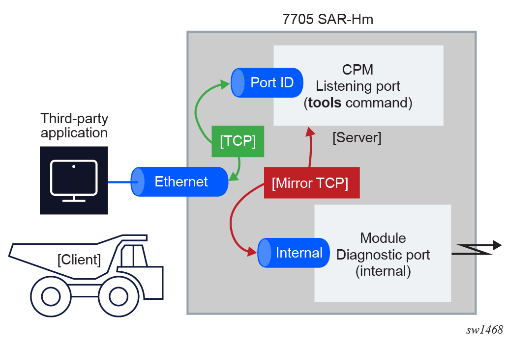
Remote access to the cellular diagnostics port is enabled by executing the tools>perform>cellular>diag-port-access>listening-port port-number>start command.The configured listening port remains active until it is disabled with the tools>perform>cellular>diag-port-access>stop command.
When enabled, the 7705 SAR-Hm series of routers act as a server for third-party applications to connect directly to the cellular modem to stream binary diagnostic information from the cellular radio in real time. The node acts as a TCP server and listens to connections on the listening port. Only one connection to the listening port is allowed at a time. The TCP connection can be established over any of the node Ethernet ports and the connection IP address (source IP address of the server) can be either the system IP address or the IP address of a base routing interface configured on the Ethernet port.
Remote access to the cellular diagnostics port shows the general mechanism for streaming cellular module diagnostic information to a third-party application that can interpret and display the information.
The status of the remote cellular diagnostics port on the 7705 SAR-Hm can be displayed on the CLI with the tools>dump>cellular>diag-port-access>status command.