System Management
This chapter provides information about configuring basic system management parameters.
Topics in this chapter include:
System Management Parameters
System management commands allow you to configure basic system management functions such as the system name, the router’s location, coordinates, and CLLI code, as well as time zones, Network Time Protocol (NTP), Simple Network Time Protocol (SNTP) properties, CRON, and synchronization properties.
System Information
System information components include:
System Name
The system name is the MIB II (RFC 1907, Management Information Base for Version 2 of the Simple Network Management Protocol (SNMPv2)) sysName object. By convention, this text string is the node’s fully qualified domain name. The system name can be any ASCII printable text string of up to 32 characters.
System Contact
The system contact is the MIB II sysContact object. By convention, this text string is a textual identification of the contact person for this managed node, together with information about how to contact this person. The system contact can be any ASCII printable text string of up to 80 characters.
System Location
The system location is the MIB II sysLocation object, which is a text string conventionally used to describe the node’s physical location; for example, ‟Bldg MV-11, 1st Floor, Room 101”. The system location can be any ASCII printable text string of up to 80 characters.
System Coordinates
The Nokia Chassis MIB tmnxChassisCoordinates object defines the system coordinates. This text string indicates the Global Navigation Satellite System (GNSS) coordinates of the location of the chassis.
Two-dimensional GNSS positioning offers latitude and longitude information as a four-dimensional vector:
(direction, hours, minutes, seconds)
where:
direction is one of the four basic values: N, S, W, E
hours range from 0 to 180 (for latitude) and 0 to 90 (for longitude)
minutes and seconds range from 0 to 60
<W, 122, 56, 89> is an example of longitude and <N, 85, 66, 43> is an example of latitude.
System coordinates can be expressed in different notations; for example:
N 45 58 23, W 34 56 12
N37 37' 00 latitude, W122 22' 00 longitude
N36 ✕ 39.246' W121 ✕ 40.121
The system coordinates can be any ASCII printable text string up to 80 characters.
Common Language Location Identifier
A Common Language Location Identifier (CLLI) code string for the device is an 11-character standardized geographic identifier that uniquely identifies the geographic location of places and specific functional categories of equipment unique to the telecommunications industry. The CLLI code is stored in the Nokia Chassis MIB tmnxChassisCLLICode object.
The CLLI code can be any ASCII printable text string of up to 11 characters.
System Identifier
A system identifier is a manually configured IPv4 address that can be used to uniquely identify the 7705 SAR in the network in situations where the more commonly used system IP address may change dynamically, causing loss of historical data attributed to the node. For example, the system IP address can change dynamically using DHCP when the 7705 SAR is acting as a DHCP client and the DHCP server-facing interface is unnumbered. In this situation, a static system identifier may be desirable.
The system identifier can be any IPv4 address.
PoE Power Source
The 7705 SAR-H supports Power over Ethernet (PoE) on all four 10/100/1000 copper Ethernet ports. To use PoE, the PoE power source must be configured at the system level as either internal or external. When the system is configured for the internal PoE power source option, PoE capability can be enabled on ports 5 and 6 only. In addition, port 5 can be enabled for PoE+ but in that case, port 6 cannot support any PoE capability. When the system is configured for the external PoE power source option, a mix of PoE and PoE+ is available on ports 5, 6, 7, and 8. See the 7705 SAR-H Chassis Installation Guide, ‟Ethernet Ports”, for information about supported combinations of PoE and PoE+.
To enable PoE or PoE+ on a PoE-capable port on the 7705 SAR-H, use the config>port>ethernet>poe command; see the 7705 SAR Interface Configuration Guide, ‟Configuration Command Reference”, for more information.
The PoE-capable ports on the 7705 SAR-H act as a Power Source Equipment (PSE) device. They support IEEE 802.3at and IEEE 802.3af.
The 7705 SAR-Wx (variants 3HE07616AA and 3HE07617AA) supports PoE+ on the RJ45 Ethernet port with PoE+. The PoE+ ports are used to deliver power to a ‟Powered Device”, such as a non-line-of-sight (NLOS) or line-of-sight (LOS) microwave radio, at levels compatible with the IEEE 802.3at standard.
To enable PoE+ on a PoE+-capable port on the 7705 SAR-Wx, use the config>port>ethernet>poe plus command; see the 7705 SAR Interface Configuration Guide, ‟Configuration Command Reference”, for more information.
System Time
The 7705 SAR routers are equipped with a real-time system clock for time-keeping purposes. When set, the system clock always operates on Coordinated Universal Time (UTC), but the 7705 SAR software has options for local time translation as well as system clock synchronization.
System time parameters include:
Time Zones
NTP
NTP is the Network Time Protocol defined in RFC 1305, Network Time Protocol (Version 3) Specification, Implementation and Analysis and RFC 5905, Network Time Protocol Version 4: Protocol and Algorithms Specification. It allows for the participating network nodes to keep time more accurately and maintain time in a more synchronized fashion among all participating network nodes.
NTP uses stratum levels to define the number of hops from a reference clock. The reference clock is considered to be a Stratum-0 device that is assumed to be accurate with little or no delay. Stratum-0 servers cannot be used in a network. However, they can be directly connected to devices that operate as Stratum-1 servers. A Stratum-1 server is an NTP server with a directly connected device that provides Coordinated Universal Time (UTC), such as a GNSS or atomic clock.
The higher stratum levels are separated from the Stratum-1 server over a network path; therefore a Stratum-2 server receives its time over a network link from a Stratum-1 server. A Stratum-3 server receives its time over a network link from a Stratum-2 server.
The 7705 SAR runs a single NTP clock that operates NTP message exchanges with external NTP clocks. Exchanges can be made with external NTP clients, servers, and peers. These exchanges can be through the base, management, or VPRN routing instances.
When NTP is enabled, the NTP clock in the 7705 SAR operates as an NTP client by default. The 7705 SAR typically operates as a Stratum-2 device, relying on an external Stratum-1 server to source accurate time into the network.
Alternatively, the NTP clock in the 7705 SAR can recover time from a local PTP or GNSS source. This is achieved by configuring the PTP clock or GNSS receiver as the internal system time. The internal system time can then be identified as the preferred source of NTP timing into the network with the command config>system>time>ntp>server>system-time>prefer. This configuration makes the local PTP or GNSS source appear as a Stratum-0 server. When the internal PTP clock or GNSS is identified as the server for NTP, NTP promotes the internal NTP server (the 7705 SAR) to Stratum-1 level, which may affect the NTP network topology.
The 7705 SAR can also operate as an NTP server and provide timing to downstream clients with the ntp-server command. When the NTP server is enabled with authentication, any NTP clients must authenticate using the correct key.
In server mode, the 7705 SAR advertises the ability to act as a clock source for other network elements. By default, the router transmits NTP packets in NTP version 4 mode. Server mode is supported on the CSM Management port, in the base routing context, and in the VPRN routing context.
As an NTP server, the 7705 SAR can peer with an external NTP server in another router that is considered more trustworthy or accurate than other routers carrying NTP in the system. This allows the peers to act as mutual backups where they can obtain time from or supply time to the other server as required. If both servers are peering each other, the router is in symmetric active mode. This mode requires that the peer association is set on both routers so that the local and remote router designate each other as a peer. If only one server is peering the other (that is, the other peer has not specifically configured the peer association), the router is in symmetric passive mode.
The 7705 SAR can be configured to transmit broadcast NTP packets on a specified interface with the broadcast command. The interface can be the management interface, interfaces in the base routing context, or an interface in the VPRN context. The messages are transmitted using a destination address that is the NTP broadcast address. Only IPv4 addressing is supported.
The 7705 SAR can also be configured to receive broadcast NTP packets on interfaces in the base routing context or on the management interface with the broadcastclient command.
The router can be configured to transmit or receive multicast NTP packets on the CSM Management port. The multicast command configures the transmission of NTP multicast messages. The multicastclient command configures the receipt of multicast NTP packets. When receiving or sending multicast NTP messages, the default address 224.0.1.1 is used. Only IPv4 addressing is supported.
The following NTP elements are supported:
authentication keys — both DES and MD5 authentication are supported as well as multiple keys, to provide increased security support in carrier and other networks
server and peer addressing — external servers and external peers may be defined using IPv4 or IPv6 addresses
alert when NTP server is not available — when none of the configured servers are reachable on the node, the system reverts to manual timekeeping and issues a critical alarm. When a server becomes available, a trap is issued indicating that standard operation has resumed.
NTP and SNTP — if both NTP and SNTP are enabled on the router, SNTP transitions to an operationally down state. If NTP is removed from the configuration or shut down, SNTP resumes an operationally up state.
NTP priority — if a higher-priority time source such as GNSS or PTP is selected on the router, NTP transitions to an operationally down state. If the higher-priority time source is disqualified or disabled, NTP resumes an operationally up state.
gradual clock adjustment — because several applications (such as Service Assurance Agent (SAA)) can use the clock, if a major adjustment (128 ms or more) must be performed, the adjustment is performed by programmatically setting the clock. If a minor adjustment (less than 128 ms) must be performed, the adjustment is performed by either speeding up or slowing down the clock.
to facilitate correct operation when the standby CSM takes over from the active CSM, the time on the secondary CSM must be synchronized with the clock of the active CSM
to prevent the generation of too many events and traps, the NTP module rate-limits the generation of events and traps to three per second. At that point, a single trap is generated that indicates that event/trap blocking is taking place.
NTP accuracy depends on the accuracy of NTP packet timestamping. By default, NTP packets are timestamped by the CSM where the NTP protocol is executed. However, an enhanced NTP mode is available where the timestamping is performed on the adapter card by the network processor. This reduces variations introduced by packet delay within the router as well as by a busy CPU in the CSM. This enhanced mode is only available for in-band NTP over a network interface. When enhanced NTP mode is used, NTP authentication is not supported.
SNTP Time Synchronization
For synchronizing the system clock with outside time sources, the 7705 SAR includes a Simple Network Time Protocol (SNTP) client. As defined in RFC 2030, SNTP Version 4 is an adaptation of the Network Time Protocol (NTP). SNTP typically provides time accuracy within 100 ms of the time source. SNTP can only receive the time from NTP servers; it cannot be used to provide time services to other systems. SNTP is a compact, client-only version of NTP. SNTP does not authenticate traffic.
SNTP can be configured in both unicast client modes (point-to-point) and broadcast client modes (point-to-multipoint). SNTP should be used only at the extremities of the synchronization subnet. SNTP clients should operate only at the highest stratum (leaves) of the subnet and in configurations where no NTP or SNTP client is dependent on another SNTP client for synchronization. SNTP time servers should operate only at the root (Stratum 1) of the subnet and then only in configurations where no other source of synchronization other than a reliable radio clock is available.
The 7705 SAR SNTP client can be configured for either broadcast or unicast client mode.
PTP
Precision Time Protocol (PTP) is a timing-over-packet protocol defined in the IEEE 1588v2 standard 1588 2008.
PTP provides the capability to synchronize network elements to a Stratum-1 clock or primary reference clock (PRC) traceable source over a network that may or may not be PTP-aware. PTP has several advantages over ACR. It is a standards-based protocol, has lower bandwidth requirements, can transport both frequency and time, and can potentially provide better performance.
For more information about PTP, see IEEE 1588v2 PTP.
Time-of-Day Measurement (ToD-1pps)
The 7705 SAR can receive and extract time of day/phase recovery from a 1588 grandmaster clock or boundary clock and transmit the recovered time of day/phase signal to an external device such as a base station through an external time of day port, where available. Transmission is through the ToD or ToD/PPS Out port with a 1 pulse/s output signal. The port interface communicates the exact time of day by the rising edge of the 1 pulse/s signal.
For more information about ToD-1pps, see PTP Ordinary TimeReceiver Clock for Time of Day/Phase Recovery.
GNSS
The 7705 SAR supports frequency synchronization via a Layer 1 interface such as synchronous Ethernet, and ToD synchronization via a protocol such as NTP or PTP. In cases where these methods are not possible, or where accuracy cannot be ensured for the service, you can deploy a GNSS receiver as a synchronous timing source. GNSS data is used to provide network-independent frequency and ToD synchronization.
GNSS receivers on the following platforms support GPS reference only, or combined GPS and GLONASS reference:
7705 SAR-Ax
7705 SAR-H with a GPS Receiver module
7705 SAR-Wx variants with a GPS RF port
7705 SAR-8 Shelf V2 with a GNSS Receiver card
7705 SAR-18 with a GNSS Receiver card
A 7705 SAR chassis equipped with a GNSS receiver and an attached GNSS antenna can be configured to receive frequency traceable to Stratum-1 (PRC/PRS). The GNSS receiver provides a synchronization clock to the SSU in the router with the corresponding QL for SSM. This frequency can then be distributed to the rest of the router from the SSU as configured with the ref-order and ql-selection commands. The GNSS reference is qualified only if the GNSS receiver is operational, has five or more satellites locked, and has a frequency successfully recovered. A PTP timeTransmitter or boundary clock can also use this frequency reference with PTP peers.
In the event of GNSS signal loss or jamming resulting in the unavailability of timing information, the GNSS receiver automatically prevents output of clock or synchronization data to the system, and the system can revert to alternate timing sources.
CRON
On the 7705 SAR, the CRON feature supports periodic and date- and time-based scheduling. CRON is used, for example, to schedule Service Assurance Agent (SAA) functions. CRON functions include specifying scripts that need to be run and when they are to be scheduled. Reboots, peer turn-ups, and SAA tests are scheduled with CRON, as well as OAM events such as connectivity checks or troubleshooting runs.
CRON supports the schedule function. The schedule function is used to configure the type of schedule to run, including one-time-only (one-shot), periodic, or calendar-based runs. All runs are scheduled by month, day, hour, minute, and interval (seconds).
Scripts that have been configured under the config>system>script-control context are referenced by the CRON schedule. For information about scripts, see CLI Script Control.
High Availability
This section discusses the high availability routing options and features available to service providers that help diminish vulnerability at the network or service provider edge and alleviate the effect of a lengthy outage on IP/MPLS networks.
High availability is an important feature in service provider routing and switching systems. High availability is gaining momentum due to the unprecedented growth of IP/MPLS services and applications in service provider networks driven by the demand from the enterprise and residential communities. Downtime can be very costly, and, in addition to lost revenue, customer information and business-critical communications can be lost. High availability is the combination of continuous uptime over long periods (Mean Time Between Failures (MTBF)) and the speed at which failover or recovery occurs (Mean Time To Repair (MTTR)).
The popularity of high availability routing is evident at the network or service provider edge where thousands of connections are hosted and rerouting options around a failed piece of equipment can often be limiting. Or, a single access link exists to a customer because of additional costs for redundant links. As service providers converge business-critical services such as real-time voice (VoIP), video, and VPN applications over their IP/MPLS networks, high availability becomes much more stringent compared to the requirements for best-effort data.
Network and service availability become critical aspects when offering advanced IP/MPLS services, which dictate that IP routers that are used to construct the foundations of these networks be resilient to component and software outages.
For high availability configuration information, see CSM Synchronization and Redundancy.
High Availability Features
As more and more critical commercial applications move onto the IP/MPLS networks, providing high availability services becomes increasingly important. This section describes high availability features for the 7705 SAR. Most of these features only apply to routers with two Control and Switching Modules (CSMs).
Redundancy
The following redundancy features enable the duplication of data elements and software functionality to maintain service continuation in case of outages or component failure.
Software Redundancy
Software outages are challenging even when baseline hardware redundancy is in place. There should be a balance to provide high availability routing; otherwise, router problems typically propagate throughout the service provider network and externally to other connected networks possibly belonging to other service providers. This could affect customers on a broad scale. There are several software availability features that contribute to the percentage of time that a router is available to process and forward traffic.
Configuration Redundancy
Features configured on the active CSM are saved on the standby CSM as well. When the active CSM fails, these features are brought up on the standby CSM that takes over the mastership.
Even with modern modular and stable software, the failure of hardware or software can cause the router to reboot or cause other service impacting events. In the best circumstances, failure leads to the initialization of a redundant route processor, which hosts the standby software configuration to become the active processor.
The 7705 SAR supports hot standby. With hot standby, the router image, configuration, and network state are already loaded on the standby; it receives continual updates from the active route processor and the swap over is immediate. Newer-generation service routers like the 7705 SAR have extra processing built into the system so that router performance is not affected by frequent synchronization, which consumes system resources.
Component Redundancy
7705 SAR component redundancy is critical to reducing MTTR for the routing system. Component redundancy consists of the following features:
dual Control and Switching modules — for a highly available architecture, redundant Control and Switching Modules (CSMs) are essential
redundant power supply feed — a power feed can be removed without impact on traffic
redundant fan — if one fan fails, the others continue to operate and provide cooling to the system without impacting traffic
hot swap — components in a live system can be replaced or become active without taking the system down or affecting traffic flow to or from other modules
Service Redundancy
During a CSM switchover, dynamically signaled SDPs and services remain up with a minimum loss of forwarded traffic.
Accounting Configuration Redundancy
When there is a switchover and the standby CSM becomes active, the accounting servers are checked, and if they are administratively up and capable of coming online (media present and so on), then the standby is brought online and new accounting files are created at that point. Users must manually copy the accounting records from the failed CSM.
Multi-Chassis LAG Redundancy
Multi-chassis LAG (MC-LAG) prevents service interruptions that are caused by 7705 SAR nodes that are taken out of service for maintenance, upgrades, or relocation. MC-LAG also provides redundancy for incidents of peer nodal failure. This improves network resiliency. When typically used at access or aggregation sites, MC-LAG ensures high availability without service disruptions by providing redundant access or aggregation nodes.
MC-LAG extends the link level redundancy provided by LAG to include protection against failure of a 7705 SAR node. With MC-LAG, a CE device can be connected to two redundant-pair peer nodes. The redundant-pair peer nodes act like a single node, using active/standby signaling to ensure that only one peer node is used at a time. The redundant-pair peer nodes appear to be a single system as they share the same MAC address and system priority when implementing MC-LAG. Availability and status information are exchanged through an MC-LAG Control Protocol (MCCP). It is used to ensure that one peer is active and to synchronize information between the peers.
A peer is configured by specifying its IP address, to which the MCCP packets are sent. The LAG ID, system priority, and MAC address for the MC-LAG are also configured under the peer. Up to 16 MC-LAGs can be configured and they can either use the same peer or different peers up to a maximum of 4 peers.
It is possible to specify the remote LAG ID in the MC-LAG lag command to allow the local and remote LAG IDs to be different on the peers. If there are two existing nodes which already have LAG IDs that do not match, and an MC-LAG is created using these nodes, then the remote LAG ID must be specified so that the matching MC-LAG group can be found. If no matching MC-LAG group is found between neighbor systems, the individual LAGs operates and no MC-LAG operation is established.
Two timer options, keep-alive-interval and hold-on-neighbor-failure, are available in the MC-LAG configuration. The keep-alive-interval option specifies the frequency of the messages expected to be received from the remote peer and is used to determine if the remote peer is still active. If hold-on-neighbor-failure messages are missed, then it is assumed that the remote peer is down.
MC-LAG at Access and Aggregation Sites shows an example of MC-LAG deployed at access and aggregation sites.
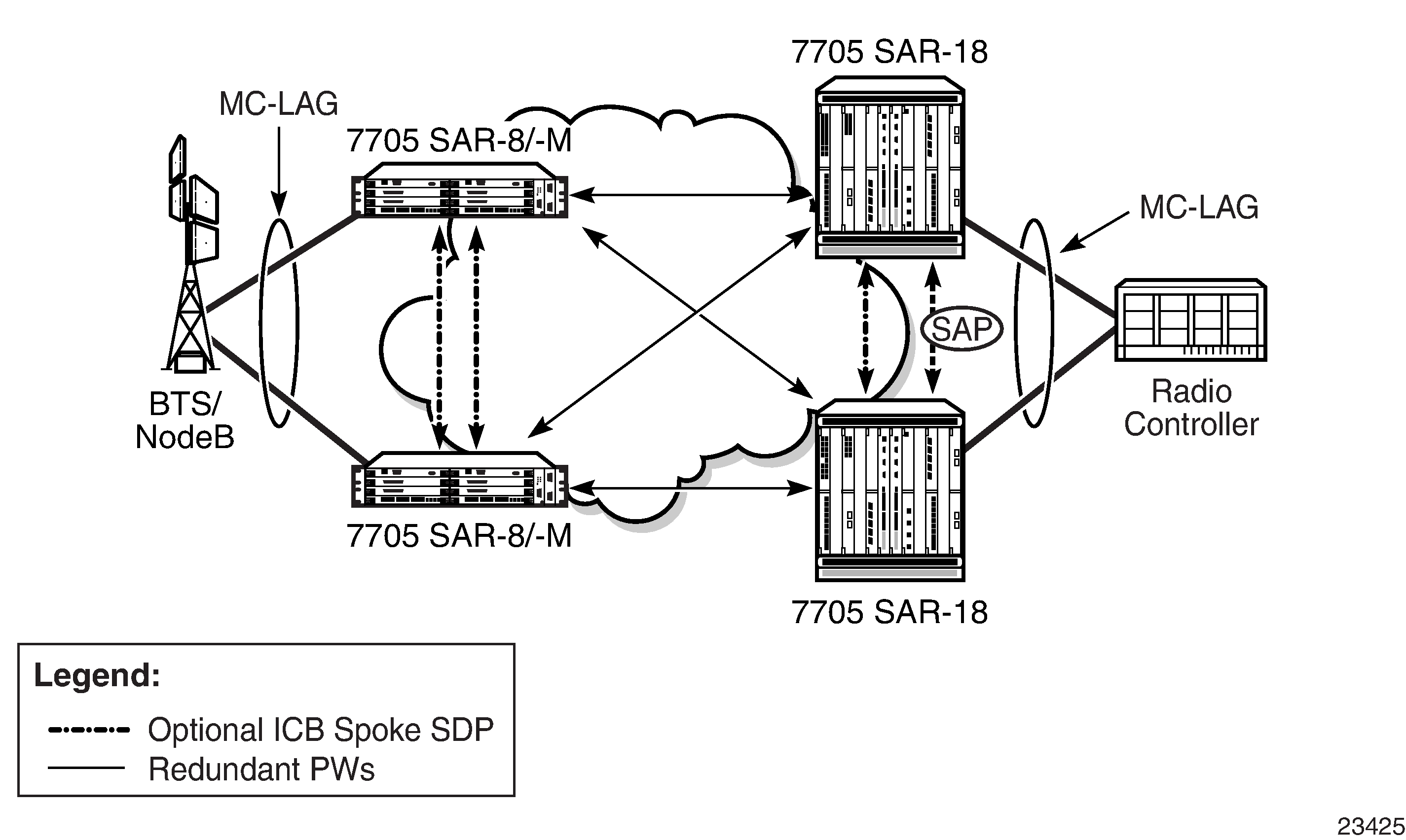
Inter-Chassis Backup (ICB) spoke SDPs are supported for use with Epipe services in an MC-LAG configuration. ICB spoke SDPs provide resiliency by reducing packet loss when an active endpoint is switched from a failed node of an MC-LAG group to a standby node. For example, if a port on an active MC-LAG node fails, the port on one of the peers becomes active, but traffic continues to route to the previously active MC-LAG node until it detects the failure. ICB spoke SDPs ensure that in-flight packets are delivered to the newly active MC-LAG node. Two ICB spoke SDPs must be created. The ICB associated with the MC-LAG on the first node must be associated with the pseudowire on the second node. Likewise, the ICB associated with the MC-LAG on the second node must be associated with the pseudowire on the first node.
Enabling the LAG slave-to-partner parameter ensures synchronized activity switching between the multi-chassis and the single-chassis endpoints. When multi-chassis endpoints are configured in slave-to-partner mode, multi-chassis endpoints always follow the single-chassis activity. The link that is promoted as active via the single-chassis endpoint is used as the active link. Enabling slave-to-partner ensures that out-of-sync scenarios do not occur for the LAG. A multi-chassis pair with pseudowire redundancy and ICBs is always able to direct traffic to the active endpoint, so enabling slave-to-partner does not impose any risk on the network side.
MC-LAG includes support for hash–based peer authentication, configurable heartbeat timers between peers, heartbeat multiplier, LAG bound to MC-LAG with LACP and support for any valid IP link between peers for the multi-chassis Control Protocol (MCCP). MC-LAG supports a configurable fault propagation delay and also provides an option to shut down a MEP on a standby endpoint.
MC-LAG maintains state across a CSM switchover event. The switchover event is transparent to peer MC-LAG nodes where sessions and state are preserved. MC-LAG is supported on the following platforms, adapter cards, and modules:
8-port Gigabit Ethernet Adapter card
6-port Ethernet 10Gbps Adapter card
10-port 1GigE/1-port 10GigE X-Adapter card (supported on the 7705 SAR-18 only)
Packet Microwave Adapter card
6-port SAR-M Ethernet module
7705 SAR-M (the port must be in access mode and autonegotiation must be off or limited)
7705 SAR-X
Nonstop Routing (NSR)
With NSR on the 7705 SAR, routing neighbors are unaware of a routing process fault. If a fault occurs, a reliable and deterministic activity switch to the inactive control complex occurs such that routing topology and reachability are not affected, even in the presence of routing updates. NSR achieves high availability through parallelization by maintaining up-to-date routing state information, at all times, on the standby route processor. This capability is achieved independently of protocols or protocol extensions, providing a more robust solution than graceful restart protocols between network routers.
The NSR implementation on the 7705 SAR applies to all supported routing protocols. NSR makes it possible to keep the existing sessions (such as LDP) during a CSM switchover, including support for MPLS signaling protocols. Peers do not see any change.
Traditionally, high availability issues have been patched through non-stop forwarding solutions. NSR overcomes these limitations by delivering an intelligent hitless failover solution.
The following NSR entities remain intact after a switchover:
ATM/IMA VPs/VCs
LDP
PPP and MLPPP sessions
RIP neighbors
In-service Upgrade
In-service upgrades allow new routing engine software and microcode to be installed on the 7705 SAR while existing services continue to operate. Software upgrades can be performed only for specific maintenance releases (generally R4 loads and higher). Software upgrades also require NSR. If software or microcode on the CSM needs to be upgraded, CSM redundancy is required.
Follow the steps below to upgrade routing engine software on the 7705 SAR without affecting existing services:
Install new software on the standby CSM.
Reboot the standby CSM for the new software to take effect.
Perform a manual switchover on the active CSM by using the force-switchover command on the CLI. The standby CSM becomes the active CSM, placing the formerly active CSM into standby.
Repeat steps 1 and 2 to upgrade the standby CSM.
CSM Switchover
During a switchover, system control and routing protocol execution are transferred from the active to the standby CSM. A switchover may occur automatically or manually.
An automatic switchover may occur under the following conditions:
a fault condition arises that causes the active CSM to crash or reboot
the active CSM is declared down (not responding)
online removal of the active CSM
Users can manually force the switchover from the active CSM to the standby CSM by using the admin redundancy force-switchover now CLI command or the admin reboot active [now] CLI command.
With the 7705 SAR, the admin reboot active [now] CLI command does not cause both CSMs to reboot.
Synchronization
Synchronization between the CSMs includes the following:
Configuration and boot-env Synchronization
Configuration and boot-env synchronization are supported in admin>redundancy> synchronize and config>redundancy>synchronize contexts.
State Database Synchronization
If a new standby CSM is inserted into the system, it synchronizes with the active CSM upon a successful boot process.
If the standby CSM is rebooted, it synchronizes with the active CSM upon a successful boot process.
When configuration or state changes occur, an incremental synchronization is conducted from the active CSM to the standby CSM.
If the synchronization fails, the standby CSM does not reboot automatically. The show redundancy synchronization command displays synchronization output information.
If the active and standby CSMs are not synchronized for some reason, users can manually synchronize the standby CSM by rebooting the standby by issuing the admin reboot standby command.
CSM Synchronization and Redundancy
The 7705 SAR uses a 1:1 redundancy scheme. Redundancy methods facilitate system synchronization between the active and standby CSMs so that they maintain identical operational parameters to prevent inconsistencies in the event of a CSM failure.
When automatic system synchronization is enabled for an entity, any save or delete file operations configured on the primary, secondary, or tertiary choices on the active CSM file system are mirrored in the standby CSM file system.
Although software configurations and images can be copied or downloaded from remote locations, synchronization can only occur locally between compact flash drives (cf3-A: and cf3-B:).
Synchronization can occur:
automatically — automatic synchronization is disabled by default. To enable automatic synchronization, the config>redundancy>synchronize command must be specified with either the boot-env parameter or the config parameter.
When the boot-env parameter is specified, the BOF, boot.ldr, config, and image files are automatically synchronized. When the config parameter is specified, only the config files are automatically synchronized.
Automatic synchronization also occurs whenever the BOF is modified with persistence on and when an admin>save command is entered with no filename specified.
manually — to execute synchronization manually, the admin>redundancy> synchronize command must be entered with the boot-env parameter or the config parameter.
When the boot-env parameter is specified, the BOF, boot.ldr, config, and image files are synchronized. When the config parameter is specified, only the config files are synchronized.
The following shows the output displayed during a manual synchronization of configuration files.
ALU-1>admin>redundancy# synchronize config

Syncing configuration......

Syncing configuration.....Completed.
ALU-1#
Active and Standby Designations
Typically, the first CSM installed in a 7705 SAR chassis assumes the role as active, regardless of being inserted in Slot A or B. The next CSM installed in the same chassis then assumes the role as the standby CSM. If two CSMs are inserted simultaneously (or almost simultaneously) and are booting at the same time, preference is given to the CSM installed in Slot A.
If only one CSM is installed in a 7705 SAR, it becomes the active CSM regardless of the slot it is installed in.
To visually determine the active and standby designations, the MS/CTL LED on the faceplate is lit green (steady) to indicate the active designation. The MS/CTL LED on the second CSM faceplate is flashing green to indicate the standby designation.
The following output shows that the CSMv2 installed in Slot A on a 7705 SAR-8 Shelf V2 is acting as the active CSM and the CSMv2 installed in Slot B is acting as the standby.
ALU-1# show card
===============================================================================
Card Summary
===============================================================================
Slot   Provisioned Type                            Admin Operational   Comments
           Equipped Type (if different)            State State
-------------------------------------------------------------------------------
1      iom-sar                                     up    up
A      csmv2-10g                                   up    up/active
B      csmv2-10g                                   up    down/standby
===============================================================================
When the Active CSM Goes Offline
When an active CSM goes offline (because of reboot, removal, or failure), the standby CSM takes control without rebooting or initializing itself. It is assumed that the CSMs are synchronized; therefore, there is no delay in operability. When the CSM that went offline boots and then comes back online, it becomes the standby CSM.
Persistence
The persistence feature allows lease information about DHCP servers to be kept across reboots. This information can include data such as the IP address, MAC binding information, and lease length information.
The system performs the following tasks to make data persistent. In systems with only one CSM, only task 1 applies. In systems with dual CSMs, both tasks apply.
When a DHCP ACK is received from a DHCP server, the entry information is written to the active CSM compact flash. If persistence fails completely (bad cflash), a trap is generated indicating that persistence can no longer be guaranteed.
DHCP message information is sent to the standby CSM, and the DHCP information is also written to the compact flash. If persistence fails on the standby CSM also, a trap is generated.
Administrative Tasks
This section contains information to perform administrative tasks:
Saving Configurations
Whenever configuration changes are made, the modified configuration must be saved so that it is not lost when the system is rebooted.
Configuration files are saved by executing explicit command syntax that includes the file URL location to save the configuration file as well as options to save both default and non-default configuration parameters. Boot options file (BOF) parameters specify where the system should search for configuration and image files as well as other operational parameters during system initialization.
For more information about the BOF, see the chapter on Boot Options in this guide.
Specifying Post-Boot Configuration Files
Two post-boot configuration extension files are supported and are triggered when either a successful or failed boot configuration file is processed. The boot-bad-exec and boot-good-exec commands specify URLs for the CLI scripts to be run following the completion of the boot-up configuration. A URL must be specified or no action is taken.
For example, after a configuration file is successfully loaded, the specified URL can contain a nearly identical configuration file with specific commands enabled or disabled, or particular parameters specified and according to the script which loads that file.
Automatic Synchronization
Use the CLI syntax displayed below to configure synchronization components relating to active-to-standby CSM switchover. In redundant systems, synchronization ensures that the active and standby CSMs have identical operational parameters, including the active configuration, CSM, and IOM images in the event of a failure or reset of the active CSM.
The force-switchover command forces a switchover to the standby CSM card.
To enable automatic synchronization, either the boot-env parameter or the config parameter must be specified. The synchronization occurs when the admin save or bof save commands are executed.
When the boot-env parameter of the synchronize command is specified, the BOF, boot.ldr, config, and image files are automatically synchronized. When the config parameter is specified, only the configuration files are automatically synchronized.
Synchronization also occurs whenever the BOF is modified with persistence on and when an admin>save command is entered with no filename specified.
Boot-Env Option
The boot-env option enables a synchronization of all the files used in system initialization.
When configuring the system to perform this synchronization, the following occurs:
The BOF used during system initialization is copied to the same compact flash on the standby CSM (in redundant systems).
Note: The synchronization parameters on the standby CSM are preserved.The primary, secondary, and tertiary images (provided they are locally stored on the active CSM) are copied to the same compact flash on the standby CSM.
The primary, secondary, and tertiary configuration files (provided they are locally stored on the active CSM) are copied to the same compact flash on the standby CSM.
Config Option
The config option synchronizes configuration files by copying the files specified in the active CSM BOF file to the same compact flash on the standby CSM.
Manual Synchronization
The admin redundancy synchronize command performs manual CSM synchronizations. The boot-env parameter synchronizes the BOF, image, and configuration files in redundant systems. The config parameter synchronizes only the configuration files in redundant systems.
Forcing a Switchover
The force-switchover now command forces an immediate switchover to the standby CSM card.
If the active and standby CSMs are not synchronized for some reason, users can manually synchronize the standby CSM by rebooting the standby by issuing the admin reboot standby command on the active CSM.
Node Timing
The 7705 SAR supports a centralized synchronization system with an SSU in each CSM. The SSU can be synchronized to a traceable primary reference clock through an external timing port, line interface, or timing-over-packet technology. The transmit clock of each T1/E1, DS3/E3, SONET/SDH port or synchronous Ethernet-capable port (referred to as a synchronous Ethernet port in this guide) can then be configured to use the node clock or alternatives.
The 7705 SAR supports three timing references — one external and two internal. The timing references can be configured as an ordered list of highest to lowest priority. The system uses an available valid timing reference with the highest priority. If a failure on the current timing reference occurs, the next highest timing reference takes over. The reference switching can be configured to operate in a revertive or non-revertive manner with the sync-if-timing revert command. Revertive switching always selects the highest-priority valid timing reference as the current source. If a reference with a higher priority becomes valid, the system automatically switches to that timing reference. Non-revertive switching means that the active timing reference remains selected while it is valid, even if a higher-priority timing reference becomes available. If the current timing reference becomes invalid, then a switch to the highest-priority available timing reference is initiated. If all the timing references fail or have not been configured, the SSU enters holdover mode of its Stratum 3 oscillator (if it was previously synchronized) or free-run mode.
The external timing reference input with a 2.048 MHz G.703 signal, 5 MHz sine wave, or 10 MHz sine wave, is available directly on the following:
7705 SAR-M
7705 SAR-H
7705 SAR-Hc
7705 SAR-A
7705 SAR-Ax
7705 SAR-X
The CSMv2 on the 7705 SAR-8 Shelf V2 does not support a 5 MHz signal. On the 7705 SAR-18, the external timing reference input with a 2.048 MHz G.703, T1 (100 Ω), or E1 (120 Ω), is supported by the BITS ports 1 and 2 located on the Alarm module.
The two internal timing references originate from timing extracted from interface ports. This timing can be recovered directly from physical layer framing on a T1/E1 port, from adaptive timing recovery for TDM pseudowires, or from a synchronous Ethernet port.
On the 7705 SAR-M, all RJ45 Ethernet ports and SFP ports support synchronous Ethernet and can supply a timing reference to be used as a source of node synchronization. On the 7705 SAR-M variants with T1/E1 ports, two T1/E1 ports can supply a timing reference. The 2-port 10GigE (Ethernet) module or 6-port SAR-M Ethernet module can supply two timing references.
On the 7705 SAR-H and 7705 SAR-Hc, all RJ45 Ethernet ports and SFP ports support synchronous Ethernet and can supply a timing reference to be used as a source of node synchronization. When the 4-port T1/E1 and RS-232 Combination module is installed in the 7705 SAR-H, a single T1/E1 port on the module can supply a timing reference; it can be independently configured for loop-timing or node-timing. When the GPS Receiver module is installed in the 7705 SAR-H, the GPS RF port can be used as a source of node synchronization.
On the 7705 SAR-A, all synchronous Ethernet ports can supply a timing reference to be used as a source of node synchronization. Synchronous Ethernet is supported on the XOR ports (1 to 4), configured as either RJ45 ports or SFP ports. Synchronous Ethernet is also supported on SFP ports 5 to 8. Ports 9 to 12 do not support synchronous Ethernet (except when 10/100/1000BaseT copper SFP is used) and, therefore, cannot be used as a timing reference. On the 7705 SAR-A variant with T1/E1 ports, two T1/E1 ports can also supply a timing reference.
On the 7705 SAR-Ax, all Ethernet ports support synchronous Ethernet and IEEE 1588v2 PTP and can supply a timing reference to be used as a source of node synchronization. The 7705 SAR-Ax can also derive its timing from a GPS antenna signal using the GNSS RF port.
On the 7705 SAR-Wx, all RJ45 Ethernet ports and SFP ports support synchronous Ethernet and IEEE 1588v2 PTP, and can supply a timing reference to be used as a source of node synchronization. For 7705 SAR-Wx variants with a GPS RF port, the GPS RF port can be used as a source of node synchronization.
On the 7705 SAR-X, all Ethernet ports support synchronous Ethernet and IEEE 1588v2 PTP. Ethernet ports and T1/E1 ports can supply two timing references to be used as a source of node synchronization. In addition, each T1/E1 port can be independently configured for loop timing.
The 7705 SAR-8 Shelf V2 and 7705 SAR-18 can receive one or two timing references depending on the port and card type supplying the reference. A timing reference can come from:
a single SONET/SDH port on the 4-port OC3/STM1 Clear Channel Adapter card
two DS3/E3 ports on the 4-port DS3/E3 Adapter card
two SONET/SDH ports on the 2-port OC3/STM1 Channelized Adapter card or 4-port OC3/STM1 / 1-port OC12/STM4 Adapter card
two synchronous Ethernet ports on:
the 6-port Ethernet 10Gbps Adapter card
the 8-port Gigabit Ethernet Adapter card
the 10-port 1GigE/1-port 10GigE X-Adapter card (supported on the 7705 SAR-18 only)
the 2-port 10GigE (Ethernet) Adapter card
two T1/E1 ports on the 16-port T1/E1 ASAP Adapter card or the 32-port T1/E1 ASAP Adapter card. References must be from different framers; the framers each have eight ports and are grouped as ports 1 to 8, 9 to 16, 17 to 24, and 25 to 32.
two ports on the Packet Microwave Adapter card: on port 1 or 2, it could be a synchronous Ethernet or PCR-enabled port; on port 3 or 4, it could be a synchronous Ethernet (optical SFP only) or PCR-enabled port (copper-based SFP only); on ports 5 through 8, it could be a synchronous Ethernet (optical SFP only) port.
the GNSS RF port on the GNSS Receiver card
The 7705 SAR-8 Shelf V2 and 7705 SAR-18 can also use IEEE 1588v2 PTP as a source of node synchronization.
Each T1/E1 port can be independently configured for loop-timing (recovered from an Rx line) or node-timing (recovered from the SSU in the active CSM).
In addition, T1/E1 CES circuits on the following can be independently configured for adaptive timing (clocking is derived from incoming TDM pseudowire packets):
16-port T1/E1 ASAP Adapter card
32-port T1/E1 ASAP Adapter card
7705 SAR-M (variants with T1/E1 ports)
7705 SAR-A (variant with T1/E1 ports)
T1/E1 ports on the 4-port T1/E1 and RS-232 Combination module
T1/E1 CES circuits on the following can be independently configured for differential timing (recovered from RTP in TDM pseudowire packets):
16-port T1/E1 ASAP Adapter card
32-port T1/E1 ASAP Adapter card
4-port OC3/STM1 / 1-port OC12/STM4 Adapter card (DS1/E1 channels)
4-port DS3/E3 Adapter card (DS1/E1 channels on DS3 ports; E3 ports cannot be channelized); DCR on DS1/E1 channels is supported only on the first three ports of the card
7705 SAR-M (variants with T1/E1 ports)
7705 SAR-A (variant with T1/E1 ports)
T1/E1 ports on the 4-port T1/E1 and RS-232 Combination module
Adaptive timing and differential timing are not supported on DS1 or E1 channels that have CAS signaling enabled.
A T1/E1 port can be configured to be a timing source for the node.
Each SONET/SDH port and each T1/E1 CES circuit on a 2-port OC3/STM1 Channelized Adapter card can be independently configured to be loop-timed or node-timed; each DS3 circuit can be independently configured to be loop-timed or free-run. A SONET/SDH port can be configured to be a timing source for the node.
Each SONET/SDH port on a 4-port OC3/STM1 Clear Channel Adapter card can be independently configured to be loop-timed or node-timed. A SONET/SDH port can be configured to be a timing source for the node.
Each SONET/SDH port on a 4-port OC3/STM1 / 1-port OC12/STM4 Adapter card can be independently configured to be node-timed; each T1/E1 CES circuit can be independently configured to be node-timed, loop-timed, or differential-timed. A SONET/SDH port can be configured to be a timing source for the node.
Each clear channel DS3/E3 port on a 4-port DS3/E3 Adapter card can be independently configured to be loop-timed, node-timed, or differential-timed. When a DS3 port is channelized, each DS1 or E1 channel can be independently configured to be loop-timed, node-timed, or differential-timed (differential timing on DS1/E1 channels is supported only on the first three ports of the card). When not configured for differential timing, a DS3/E3 port can be configured to be a timing source for the node.
External Timing Mode
The external input and output timing ports are located on the CSM on the 7705 SAR-8 Shelf V2 and directly on the 7705 SAR-H and 7705 SAR-M. The 7705 SAR-A, 7705 SAR-Ax, and 7705 SAR-X have an external timing input port only, located on their faceplates. The external input timing port allows the SSU to be synchronized to an external timing reference. The external output timing port provides a synchronization output signal from the 7705 SAR to an external device. These external timing references typically would come from a GNSS, Building Integrated Timing System (BITS), or the external output timing ports from other telecom equipment.
The timing ports can be configured for the following:
2.048 MHz G.703 section 13 signal
5 MHz sine wave (not available on the 7705 SAR-8 Shelf V2 CSMv2)
10 MHz sine wave
On the 7705 SAR-18, the BITS ports 1 and 2 can be configured for the following:
2.048 MHz G.703 section 13 signal
T1 (ESF or SF)
E1 (PCM30CRC or PCM31CRC)
When redundant CSMs are used on the 7705 SAR-8 Shelf V2, the external synchronization inputs in each CSM must come from the same synchronization source; that is, you cannot select each input of the two CSMs as two of the three timing references. A Y-cable can be used to connect to a single reference connector. The synchronization output on each CSM is clocked by its own SSU clock.
On the 7705 SAR-18, either BITS port 1 or port 2 is available as an input and output source. When both inputs are connected and available, then the quality level (QL) from Synchronization Status Messaging (SSM) is used to determine which port is used by the CSMs as the BITS input. If SSM is not available, then BITS port 1 is the preferred input. BITS port 2 is used if BITS port 1 is not available. In this case, the operation is non-revertive. The BITS output ports 1 and 2 are clocked by the active CSM’s SSU clock.
The BITS output source command can be used to configure the BITS output ports’ source path on the 7705 SAR-18 to be either:
the filtered clock from the Synchronous Equipment Timing Generator (SETG)
the alternate unfiltered path from the BITS output port via Selector A and C, as per ITU-T G.8262
BITS Timing Source Path shows an example of a timing source path. The BITS port is configured to deliver an input reference directly to a dedicated timing device such as a BITS or standalone synchronization equipment (SASE) device in a customer facility. The external BITS clock can have multiple references and can provide a common high-quality clock to all network elements at the customer location, including the 7705 SAR-18 node.
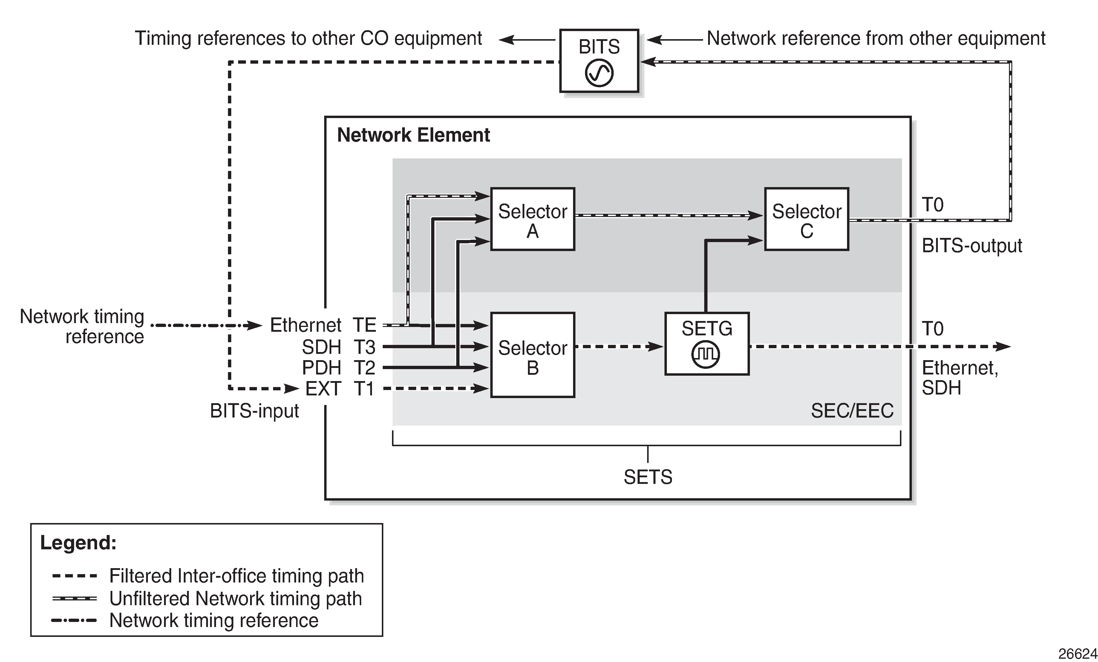
When configuring the priority order of the timing references with the ref-order command for unfiltered BITS output (T4), all reference sources are valid options, except the BITS input, which is excluded to avoid a timing loop. Because the same priority order is used for the SETG output (T0), the BITS input option must be set as the first (highest-priority) reference option.
Because both input and output clock pins are inside the physical RJ45 port for each BITS port, a custom cable is required to connect input and output ports to different equipment. See the 7705 SAR-18 Chassis Installation Guide, BITS Ports and Pinouts.
Line Timing Mode
Line timing from a synchronous port, such as a T1/E1 port or synchronous Ethernet port, provides the best synchronization performance through a synchronization distribution network. Line timing mode derives an 8 kHz clock from the framing of T1/E1, DS3/E3, and SONET/SDH signaling that can be used as an accurate reference between nodes in a network. Line timing mode is immune to any packet delay variation (PDV) occurring on Layer 2 or Layer 3 links.
On the 7705 SAR-M variants with T1/E1 ports, line timing is supported on the T1/E1 ports. Line timing is also supported on all RJ45 Ethernet ports and SFP ports on the 7705 SAR-M and on the following 7705 SAR-M modules:
2-port 10GigE (Ethernet) module
6-port SAR-M Ethernet module
On the 7705 SAR-X, line timing is supported on T1/E1 ports and Ethernet ports.
On the 7705 SAR-H and 7705 SAR-Hc, line timing is supported on all Ethernet ports. Line timing is also supported on the following 7705 SAR-H modules:
4-port SAR-H Fast Ethernet module
T1/E1 ports of the 4-port T1/E1 and RS-232 Combination module
On the 7705 SAR-A variant with T1/E1 ports, line timing is supported on the T1/E1 ports. Line timing is also supported on all synchronous Ethernet ports on the 7705 SAR-A. Synchronous Ethernet is supported on the XOR ports (1 to 4), configured as either RJ45 ports or SFP ports. Synchronous Ethernet is also supported on SFP ports 5 to 8. Ports 9 to 12 do not support synchronous Ethernet and therefore do not support line timing.
On the 7705 SAR-Ax, line timing is supported on all Ethernet ports.
On the 7705 SAR-Wx, line timing is supported on all Ethernet RJ45 ports and SFP ports.
On the 7705 SAR-8 Shelf V2 and 7705 SAR-18, line timing is supported on the following adapter cards:
16-port T1/E1 ASAP Adapter card
32-port T1/E1 ASAP Adapter card
6-port Ethernet 10Gbps Adapter card
8-port Gigabit Ethernet Adapter card (dual-rate and copper SFPs do not support synchronous Ethernet)
2-port 10GigE (Ethernet) Adapter card
10-port 1GigE/1-port 10GigE X-Adapter card (supported on the 7705 SAR-18 only)
4-port DS3/E3 Adapter card
2-port OC3/STM1 Channelized Adapter card
4-port OC3/STM1 / 1-port OC12/STM4 Adapter card
4-port OC3/STM1 Clear Channel Adapter card
Packet Microwave Adapter card on ports that support synchronous Ethernet and on ports that support PCR
Adaptive Clock Recovery (ACR)
Adaptive Clock Recovery (ACR) is a timing-over-packet technology that transports timing information via periodic packet delivery over a pseudowire. ACR may be used when there is no other Stratum 1 traceable clock available.
ACR is supported on T1/E1 CES circuits on the following:
16-port T1/E1 ASAP Adapter card
32-port T1/E1 ASAP Adapter card
7705 SAR-M (variants with T1/E1 ports)
7705 SAR-A (variant with T1/E1 ports)
T1/E1 ports of the 4-port T1/E1 and RS-232 Combination module
T1/E1 ports on the 7705 SAR-X
ACR is not supported on DS1 or E1 channels that have CAS signaling enabled.
ACR is supported for Cpipe services. In addition, ACR is supported on MEF 8 Epipe services. The MEF 8 Epipe may be a TDM SAP to Ethernet SAP or a TDM SAP to spoke SDP. See the 7705 SAR Services Guide, ‟MEF 8”, for information about MEF 8.
There is no extra equipment cost to implement ACR in a network because this technique uses the packet arrival rate of a TDM pseudowire within the 7705 SAR to regenerate a clock signal. Additionally, the nodes in the network that are traversed between endpoints do not need special ACR capabilities. However, because the TDM pseudowire is transported over Layer 2 links, the packet flow is susceptible to PDV.
To achieve the best ACR performance, follow these recommendations:
use a packet rate between 1000 pps and 4000 pps. Lower packet rates cause ACR to be more susceptible to PDV in the network.
limit the number of nodes traversed between the source end and the ACR end of the TDM pseudowire
enable QoS in the network with the TDM pseudowire enabled for ACR classified as NC (network control)
maintain a constant temperature as much as possible, because temperature variations will affect the natural frequency on the internal oscillators in the 7705 SAR
ensure that the network does not contain a timing loop when it is designed
ACR States
There are five potential ACR states:
normal
phase tracking
frequency tracking
holdover
free-run
When a port’s ACR state is normal, phase tracking, or frequency tracking, the recovered ACR clock is considered a qualified reference source for the SSU. If this reference source is being used, then transitions between any of these three states do not affect SSU operation.
When a port’s ACR state is free-run or holdover, the recovered ACR clock is disqualified as a reference source for the SSU. If this reference source is being used, then transitions to either of these two states cause the SSU to drop the reference and switch to the next highest prioritized reference source. This can potentially be SSU holdover.
ACR Statistics
The system collects statistics on all ACR-capable ports. ACR statistics detail how the digital phase locked loop (DPLL) is functioning in one or more ACR instances in the adapter card. ACR statistics assist with isolating a problem during degraded synchronization performance or with anticipating future issues.
Within the DPLL, there are two values that contribute to ACR statistics:
DCO frequency
input phase error of each 2-second update interval
The DCO is the digitally controlled oscillator that produces the regenerated clock signal. The input phase error is the correction signal that provides feedback to the DPLL to tune the DCO output. The input phase error should approach zero as the DPLL locks in to the source timing information and stabilizes the output.
The continuous 2-second updates to the output DCO frequency are directly applied as the clock output of the ACR instance. ACR statistics allow you to view the mean frequency and the standard deviation of the output DCO frequency.
During every 2-second update interval, the input phase error and the output DCO frequency are recorded. The input phase error mean, input phase error standard deviation, output DCO mean (Hz and ppb), and output DCO standard deviation are calculated every 60 seconds.
Entering a show CLI command on a port with ACR displays the mean and standard deviation values for the previous 60-second interval. A show detail command on the same port displays the previous 15 sets of 60-second intervals and a list of state and event counts. An SNMP MIB is also available with these statistics.
Differential Clock Recovery (DCR)
Differential Clock Recovery (DCR) is an alternative method to ACR to maintain the service clock across the packet network for a circuit emulated service. DCR is supported on:
-
16-port T1/E1 ASAP Adapter card
-
32-port T1/E1 ASAP Adapter card
-
4-port OC3/STM1 / 1-port OC12/STM4 Adapter card (DS1/E1 channels)
-
4-port DS3/E3 Adapter card (clear channel DS3/E3 ports and DS1/E1 channels on channelized DS3 ports (E3 ports cannot be channelized)); DCR on DS1/E1 channels is supported only on the first three ports of the card
-
7705 SAR-M (variants with T1/E1 ports)
-
7705 SAR-A (variant with T1/E1 ports)
-
T1/E1 ports of the 4-port T1/E1 and RS-232 Combination module
-
T1/E1 ports on the 7705 SAR-X
In addition, DCR is supported between TDM SAPs and Ethernet SAPs and between TDM SAPs and spoke SDPs in a MEF 8 configuration for the above platforms, adapter cards, and modules. See the 7705 SAR Services Guide, ‟MEF 8”, for information about MEF 8.
DCR is not supported on DS1 or E1 channels that have CAS signaling enabled.
DCR uses channel group 1 for timing recovery. If a T1 or E1 port is channelized, all TDM PWs that share the port use the timing recovered from channel group 1.
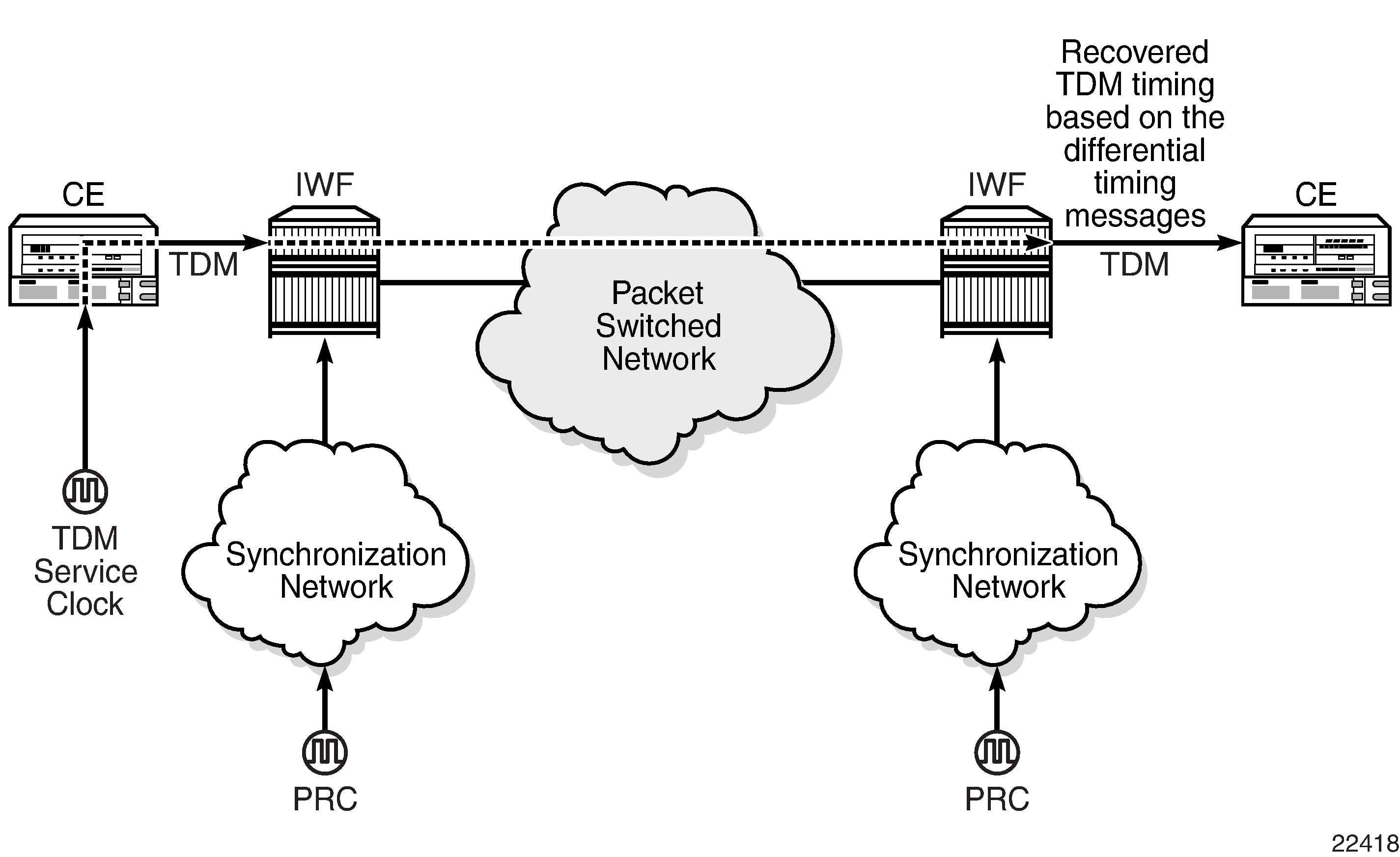
To enable DCR, the network must have a common clock between the routers performing the TDM-to-packet interworking function or between the two terminating SAPs or SAP/spoke SDP using MEF 8. The common clock can come from two PRC-traceable clocks or one clock that is made available to both ends, such as the transmitted clock of a SONET/SDH or synchronous Ethernet port.
In each direction, the service clock is compared to the common clock and the difference is encoded into the RTP header in the TDM PW overhead. At the other end of the network, the original service clock is reproduced by comparing the common clock to the frequency difference in the RTP header. Differential Clock Recovery on a Network shows an example of a network using DCR.
RTP headers are disabled by default and must be enabled for all circuit emulation services that require DCR. RTP must be enabled for the TDM PW that uses channel group 1. All channel groups on the same DS1 or E1 channel must be configured for the same mode of operation.
To achieve the best DCR performance, it is recommended that you use a Layer 1 network synchronization method to ensure the common clock has the best stability. If a timing-over-packet technique is used to transfer the common clock, then the number and type of nodes, the traffic profile, and the temperature variations will affect DCR synchronization performance. As well, a packet rate of at least 200 pps is recommended (up to 4000 pps is supported). Packet rates lower than 200 pps may affect system performance.
DCR Frequencies
Each DS1, E1, DS3, or E3 circuit configured with DCR executes its own clock recovery from the packet stream. This allows each circuit to have an independent frequency.
Supported Timestamp Frequencies for DCR-timed Circuits lists the supported timestamp frequencies for each platform and adapter card.
|
Timestamp Frequency (MHz) |
||||
|---|---|---|---|---|
|
103.68 |
77.76 |
25 |
19.44 |
|
|
16-port T1/E1 ASAP Adapter card |
✓ (default) |
✓ |
||
|
32-port T1/E1 ASAP Adapter card |
✓ (default) |
✓ |
||
|
4-port OC3/STM1 / 1-port OC12/STM4 Adapter card |
✓ (default) |
|||
|
4-port DS3/E3 Adapter card |
✓ (default) |
|||
|
7705 SAR-M |
✓ (default) |
✓ |
✓ |
✓ |
|
7705 SAR-A |
✓ (default) |
✓ |
✓ |
✓ |
|
4-port T1/E1 and RS-232 Combination module |
✓ (default) |
✓ |
✓ |
✓ |
|
7705 SAR-X |
✓ (default) |
✓ |
✓ |
✓ |
The timestamp frequency is configured at the adapter card level and is used by all DCR ports or channels on the supporting platforms and cards. Both ends of a TDM pseudowire using DCR must be running the same frequency. If a network contains different types of equipment using DCR, a common frequency must be selected that is supported by all equipment.
DCR complies with published jitter and wander specifications (G.823, G.824, and G.8261) for traffic interfaces under typical network conditions and for synchronous interfaces under specified packet network delay, loss, and delay variance (jitter) conditions.
Serial Clock Transport (DCR Serial)
A dcr-serial parameter option is available on the 12-port Serial Data Interface card, version 3, to support the SAToP serial virtual channel (vc) type of Cpipe. The dcr-serial option can be configured using the serial>clock-source command; it is only supported on synchronous RS-232 and RS-530 interfaces. See the 7705 SAR Interface Configuration Guide, ‟Serial Commands”, for more information about how to configure DCR serial. See the 7705 SAR Services Guide, ‟SAToP Serial”, for information about SAToP serial.
During the normal transport of serial data traffic across a 7705 SAR IP/MPLS network, the time reference used to clock the data in/out of the 7705 SAR to the end device is based on the 7705 SAR system clock.
Some encryption applications, however, require both end devices on an encrypted link to run off the same time reference. To meet this requirement, the dcr-serial option is used to transport the system clock but only in a single direction: from the DTE-designated port of a SAToP serial Cpipe to the DCE-designated port at the other end. The source of the service clock is referenced to the Rx Clk signal of the DTE port on the 12-port Serial Data Interface card, version 3. One end of the a SAToP serial Cpipe must be set to DTE while the other end is set to DCE.
Only one clock can be transported per port.
The clock recovered by DCR serial is suitable only for clocking data into the attached device, not as a source of network synchronization.
The input frequency clock tolerance must within 4.5% of the configured port rate.
Although DCR serial is supported on 600 b/s port speeds, clock deviations from a nominal 600 b/s port speed are not supported. This applies to both RS-232 and RS-530 ports.
There can be a maximum of 12 DCR serial timing instances per 12-port Serial Data Interface card, version 3.
Proprietary Clock Recovery (PCR)
PCR is a copper synchronous Ethernet-based, timing-over-packet technology. It is supported on the Packet Microwave Adapter card on the two copper RJ45 synchronous Ethernet 1000Base-T Microwave Awareness (MWA) ports (ports 1 and 2) and on a copper SFP Ethernet port (ports 3 and 4).
There is no CLI configuration requirement for PCR; it is turned on automatically when a microwave link is enabled on an MWA RJ45 port or on a copper SFP Ethernet port (ports 3 and 4).
PCR provides the same frequency recovery capability as standard-based copper synchronous Ethernet without having to endure a traffic hit whenever a synchronous source switching occurs. See Proprietary Clock Recovery.
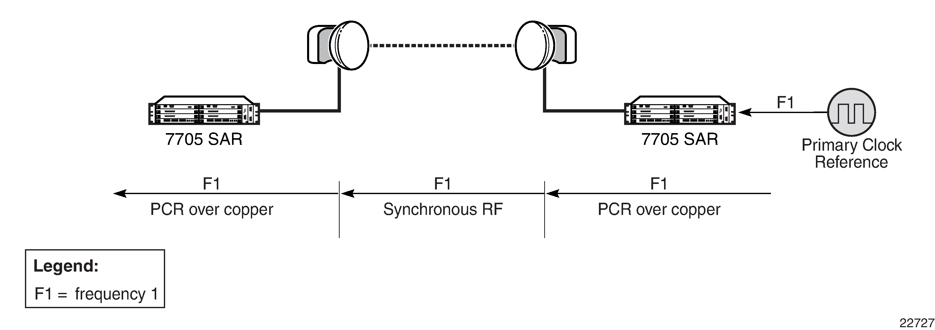
By running PCR between the MPR-e radio and the MWA port, frequency synchronization can be delivered in either direction. With standard-based copper synchronous Ethernet, there is a traffic hit every time a clock source change occurs on a 7705 SAR-8 Shelf V2 or 7705 SAR-18 because the 7705 SAR-8 Shelf V2 or 7705 SAR-18 and the MPR-e radio to which it is connected must bring down the Ethernet link MAC layer before it can renegotiate and reverse the master and slave clock role. This MAC layer renegotiation affects the data plane and the signaling and routing plane. All MPLS signaling links and the label switched path (LSP) are taken down during the renegotiation process; the routing signaling advertises the down state of the link throughout the network.
However, with PCR running on the microwave link, the physical layer transmit clock on a copper synchronous Ethernet port on the Packet Microwave Adapter card is always set to master. The reversal of the clock role only occurs at the PCR ‟layer”. This means that a synchronous source change does not disrupt the data plane and the signaling and routing plane on the 7705 SAR-8 Shelf V2 or 7705 SAR-18.
IEEE 1588v2 PTP
Precision Time Protocol (PTP) is a timing-over-packet protocol defined in the IEEE 1588v2 standard 1588 2008.
PTP can be deployed as an alternative timing-over-packet option to ACR. PTP provides the capability to synchronize network elements to a Stratum-1 clock or primary reference clock (PRC) traceable source over a network that may or may not be PTP-aware. PTP has several advantages over ACR. It is a standards-based protocol, has lower bandwidth requirements, can transport both frequency and time, and can potentially provide better performance.
There are five basic types of PTP devices, as listed below:
ordinary clock (timeTransmitter or timeReceiver)
boundary clock
end-to-end transparent clock
peer-to-peer transparent clock
management node
IEEE 1588v2 PTP Support per Fixed Platform lists the types of PTP support on each fixed platform; IEEE 1588v2 PTP Support per Card on the 7705 SAR-8 Shelf V2 and 7705 SAR-18 lists the types of PTP support on each adapter card for the 7705 SAR-8 Shelf V2 and the 7705 SAR-18.
All clock types, with the exception of transparent clock, support PTP messaging using UDP/ IPv4 or UDP/IPv6.
IPv6 messaging is supported on all platforms and cards listed in IEEE 1588v2 PTP Support per Fixed Platform and IEEE 1588v2 PTP Support per Card on the 7705 SAR-8 Shelf V2 and 7705 SAR-18 .
Boundary clocks support dual mode; that is, the clock can be configured for both IPv4 and IPv6. Dual mode is not supported on ordinary clocks; the clock can only be configured for IPv4 or IPv6.
Sync Type |
PTP Clock Type |
7705 SAR-A 7705 SAR-Ax 7705 SAR-H 7705 SAR-Hc 7705 SAR-M 7705 SAR-Wx 7705 SAR-X |
|---|---|---|
Freq |
Ordinary timeReceiver |
✓ |
Boundary clock |
✓ |
|
End-to-end transparent clock |
✓ |
|
Ordinary timeTransmitter |
✓ |
|
Time of day/phase |
Ordinary timeReceiver |
✓ |
Boundary clock |
✓ |
|
End-to-end transparent clock |
✓ 1 |
|
Ordinary timeTransmitter |
✓ 2 |
Notes:
- The 2-port 10GigE (Ethernet) module supports transparent clock functionality when installed in the 7705 SAR-M
- Only supported on the 7705 SAR-H with a GPS Receiver module and 7705 SAR-Wx variants with a GPS RF port.
All the platforms listed in IEEE 1588v2 PTP Support per Fixed Platform support one ordinary timeReceiver clock, ordinary timeTransmitter clock, or boundary clock. The platforms also support an additional PTP clock for transparent clock functionality.
|
Sync Type |
PTP Clock Type |
6-port Ethernet 10Gbps Adapter Card |
8-port Gigabit Ethernet Adapter Card |
Packet Microwave Adapter Card |
2-port 10GigE (Ethernet) Adapter Card |
10-port 1GigE/1-port 10GigE X-Adapter Card 1 |
|---|---|---|---|---|---|---|
|
Freq |
Ordinary timeReceiver |
✓ |
✓ |
✓ |
✓ |
✓ |
| Boundary clock |
✓ |
✓ |
✓ |
✓ |
✓ |
|
|
End-to-end transparent clock |
||||||
| Ordinary timeTransmitter |
✓ |
✓ |
✓ |
✓ |
✓ |
|
|
Time of day/phase |
Ordinary timeReceiver |
✓ |
✓ |
✓ |
✓ |
✓ |
| Boundary clock |
✓ |
✓ |
✓ |
✓ |
✓ |
|
| End-to-end transparent clock | ||||||
| Ordinary timeTransmitter 2 |
✓ |
✓ |
✓ |
✓ |
✓ |
Notes:
- Not supported on the 7705 SAR-8 Shelf V2.
- Supported on chassis with an active GNSS Receiver card.
The 7705 SAR-8 Shelf V2 supports up to six ordinary timeReceiver clocks, ordinary timeTransmitter clocks, or boundary clocks. The 7705 SAR-18 supports up to eight ordinary timeReceiver clocks, ordinary timeTransmitter clocks, or boundary clocks.
Each of the cards listed in IEEE 1588v2 PTP Support per Card on the 7705 SAR-8 Shelf V2 and 7705 SAR-18 supports one PTP clock.
A nodal clock is equipped in each CSM on the 7705 SAR-8 Shelf V2 and 7705 SAR-18 or directly on the fixed platforms listed in IEEE 1588v2 PTP Support per Fixed Platform. Up to two PTP ordinary or boundary clocks can be configured per node as references to the nodal clock.
Each PTP timeReceiver clock can be configured to receive timing from up to two PTP timeTransmitter clocks in the network.
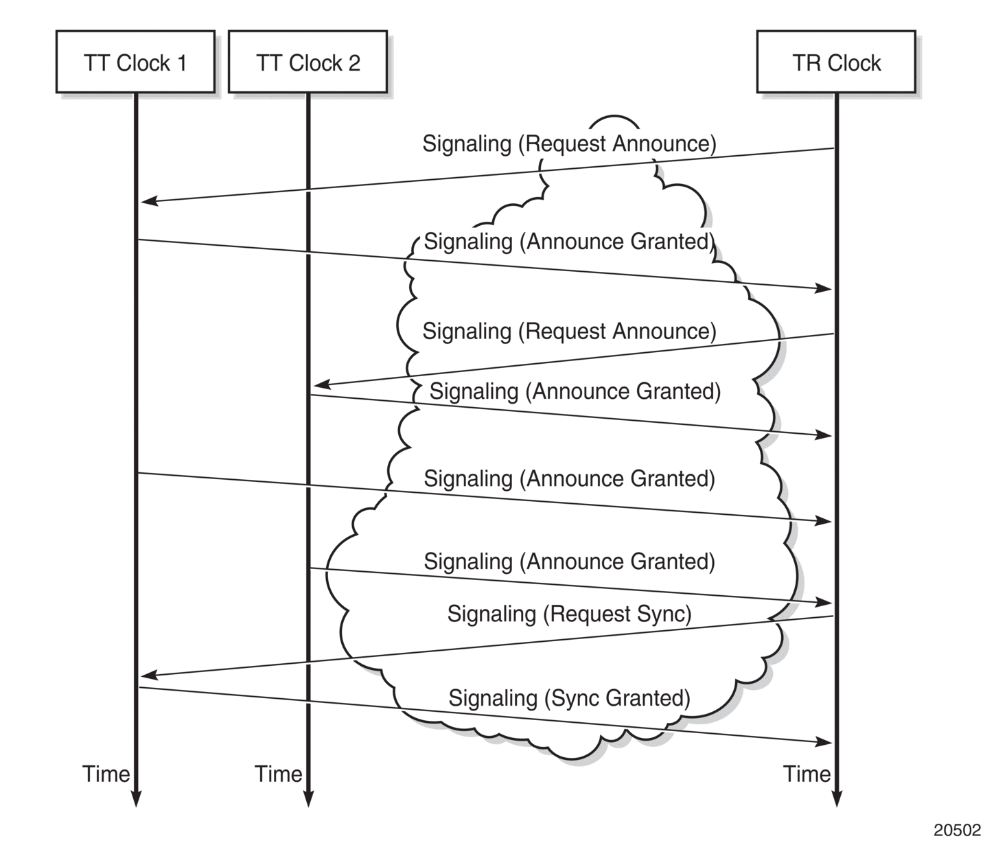
Best TimeTransmitter Clock Algorithm
Each timeTransmitter clock has its own configuration for IP address, packet rate, and messaging timeouts, and for statistics, alarms, and events. Each available timeTransmitter clock advertises its presence and information using Announce messages. If both timeTransmitter clocks are available, the timeReceiver clock uses the Best TimeTransmitter Clock Algorithm (BTCA) to dynamically compare the information in the Announce messages of each timeTransmitter clock to determine to which of the two timeTransmitter clocks it should synchronize. This timeTransmitter clock is known as the best timeTransmitter. After the timeReceiver clock has determined which is the best timeTransmitter, it can begin to negotiate with it for unicast synchronization communication.
The configured setting for the profile command determines the precedence order for selecting the best timeTransmitter clock algorithm. The 7705 SAR supports the following profile settings: ieee1588-2008, itu-telecom-freq, g8275dot1-2014, g8275dot2-2016, iec-61850-9-3-2016, and c37dot238-2017. For information about the g8275dot1-2014 and g8275dot2-2016 profile parameters, see ITU-T G.8275.1 and G.8275.2. For information about the iec-61850-9-3-2016 and c37dot238-2017 profile parameters, see IEC/IEEE 61850-9-3 and C37.238-2017.
If the profile setting for the clock is ieee1588-2008, iec-61850-9-3-2016, or c37dot238-2017, the precedence order for the best timeTransmitter selection algorithm is as follows:
priority1 (user-configurable on the timeTransmitter clock side)
clock class
clock accuracy
PTP variance (offsetScaledLogVariance)
priority2 (user-configurable on the timeTransmitter clock side)
clock identity
distance (number of boundary clocks)
If the profile setting for the clock is itu-telecom-freq (ITU-T G.8265.1 profile), the precedence order for the best timeTransmitter selection algorithm is as follows:
clock class
peer ID
If the profile setting for the clock is g8275dot1-2014 or g8275dot2-2016, the precedence order for the best timeTransmitter selection algorithm is as follows if the grandmaster clock is connected to a primary reference time clock (PRTC) in locked mode:
clock class
clock accuracy
PTP variance (offsetScaledLogVariance)
priority2 (user-configurable on the timeTransmitter clock side)
localPriority
steps removed from the grandmaster
port identities
port numbers
If the profile setting for the clock is g8275dot1-2014 or g8275dot2-2016, the precedence order for the best timeTransmitter selection algorithm is as follows if the grandmaster clock is in holdover and out of holdover specification, or is without a time reference since startup:
clock class
clock accuracy
PTP variance (offsetScaledLogVariance)
priority2 (user-configurable on the timeTransmitter clock side)
localPriority
clock identity
steps removed from the grandmaster
port identities
port numbers
The following figure shows an example of the messaging sequence between the PTP timeReceiver clock and the two PTP timeTransmitter clocks.
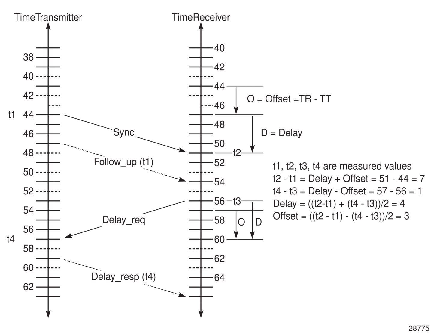
PTP Clock Synchronization
The IEEE 1588v2 standard synchronizes the frequency and time from a timeTransmitter clock to one or more timeReceiver clocks over a packet stream. This packet-based synchronization can be over UDP/IP or Ethernet and can be unicast (for IP) or multicast (for Ethernet). For UDP/IP, both IPv4 and IPv6 unicast mode with unicast negotiation is supported.
As part of the basic synchronization timing computation, a number of event messages are defined for synchronization messaging between the PTP timeReceiver clock and PTP timeTransmitter clock. A one-step or two-step synchronization operation can be used, with the two-step operation requiring a follow-up message after each synchronization message. Currently, only one-step operation is supported when the 7705 SAR is a timeTransmitter clock; PTP frequency and time can be recovered from both one-step and two-step operation when the 7705 SAR is acting as a timeReceiver or boundary clock.
For IPv4, the two-step operation is optional. For IPv6, the two-step operation is a mandatory requirement for the 7705 SAR.
In one-step operation, a timestamp is inserted in the synchronization message when the packet is transmitted to the timeReceiver clock. In two-step operation, the timestamp is sent in the follow-up message. If the timestamp is changed in the synchronization message, the checksum field is recomputed. Because the checksum field is a mandatory field for IPv6 (optional for IPv4), the 7705 SAR requires the timestamp to be sent separately to avoid potential checksum corruption in the packet.
During startup, the PTP timeReceiver clock receives the synchronization messages from the PTP timeTransmitter clock before a network delay calculation is made. Before any delay calculation, the delay is assumed to be zero. A drift compensation is activated after a number of synchronization message intervals occur. The expected interval between the reception of synchronization messages is user-configurable.
The basic synchronization timing computation between the PTP timeReceiver clock and PTP best timeTransmitter is illustrated in the following figure. This figure illustrates the offset of the timeReceiver clock referenced to the best timeTransmitter signal during startup.
Performance Considerations
Although IEEE 1588v2 can be used on a network that is not PTP-aware, the use of PTP-aware network elements (boundary clocks) within the packet switched network improves synchronization performance by reducing the impact of PDV between the grandmaster clock and the timeReceiver clock.
The grandmaster clock is the timeTransmitter clock for the network. The best timeTransmitter clock is the clock that the timeReceiver clock selects as its timeTransmitter. For example, the timeReceiver clock’s best timeTransmitter clock may be a boundary clock, which is connected to a grandmaster clock.
A 7705 SAR equipped with a GNSS receiver can function as a grandmaster clock.
The performance objective is to meet the synchronization interface maximum time interval error (MTIE) mask. Similar to ACR, the number of factors with the PSN contributes to how well PTP can withstand, and still meet, those requirements.
PTP Capabilities
PTP messages are supported via IPv4 unicast with a fixed IP header size or via IPv6.
PTP messaging is supported on network interfaces. If a node loopback address is used as the source interface for 1588 packets, the packets can ingress any network IP interface on the router. If the source interface is associated with a physical port, packets must be sent to the interface on that port.
PTP messaging is also supported on IES interfaces for access ports.
The 7705 SAR can also forward IPv4-encapsulated PTP messages over BGP-LU routes for frequency synchronization. The following profiles are supported for these messages: ieee1588-2008, itu-telecom-freq, and g8275dot2-2016.
The following table describes the supported message rates for timeReceiver and timeTransmitter states for IP-encapsulated PTP traffic, based on the profile configured. The ordinary clock can be either in the timeReceiver or timeTransmitter state. The boundary clock can be in both of these states.
ieee1588-2008 |
itu-telecom-freq |
g8275dot1-2014 g8275dot2-2016 |
||
|---|---|---|---|---|
Announce |
Minimum rate |
1 per 16 seconds |
1 per 16 seconds |
1 per 16 seconds |
Maximum rate |
8 per second |
8 per second |
8 per second |
|
Default rate |
1 per 2 seconds |
1 per 2 seconds |
8 per second |
|
Sync and Delay |
Minimum rate1 |
64 per second |
64 per second |
16 per second |
Maximum rate |
128 per second |
128 per second |
128 per second |
|
Default rate |
64 per second |
64 per second |
16 per second |
|
Note:
- In the timeTransmitter clock state, the minimum rate granted is 1 per 16 seconds if requested by the timeReceiver clock.
See Rates for Ethernet-Encapsulated PTP Messages for the supported message rates for Ethernet-encapsulated PTP traffic.
State and statistics data for each timeTransmitter clock are available to assist in the detection of failures or unusual situations.
The PTP algorithm is able to recover the clock using both the upstream and downstream directions in both ordinary timeReceiver and boundary clock modes. The ability to perform bidirectional recovery improves the performance of networks where the upstream and downstream load is not symmetrical.
The Bell Labs algorithm looks at the PTP packet exchange in both directions between the timeTransmitter and timeReceiver. There can be more packet delay variation in one direction if there is a high utilization rate or congestion in that direction. The algorithm assesses the stability and reliability of the packet exchange in each direction and assigns weight values based on the results. The system gives preference to frequency synchronization from the direction with a higher weight value. The weight values change dynamically and can be viewed with detailed PTP show commands.
PTP Ordinary TimeReceiver Clock For Frequency
The PTP ordinary clock with timeReceiver capability on the 7705 SAR provides an option to reference a Stratum-1 traceable clock across a packet switched network. The recovered clock can be referenced by the internal SSU and distributed to all slots and ports.
The following figure shows a PTP ordinary timeReceiver clock network configuration.
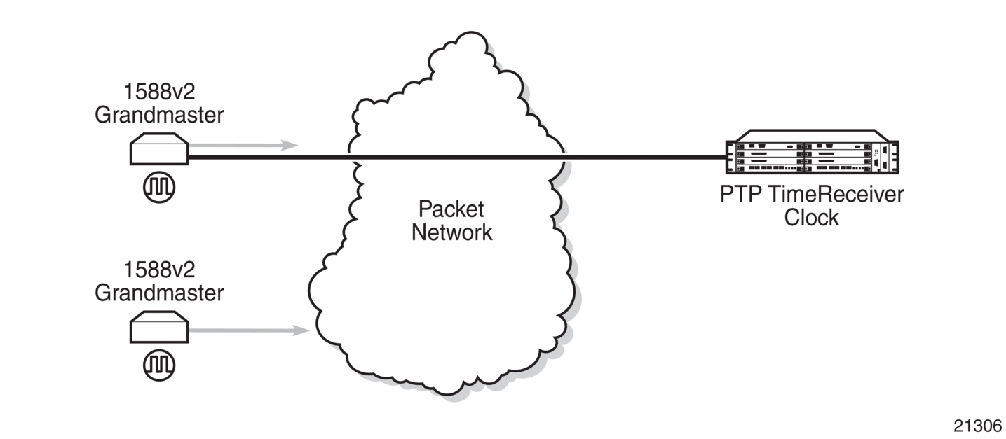
The PTP timeReceiver capability is implemented on the Ethernet ports of the platforms listed in IEEE 1588v2 PTP Support per Fixed Platform and on the cards listed in IEEE 1588v2 PTP Support per Card on the 7705 SAR-8 Shelf V2 and 7705 SAR-18 .
The 7705 SAR-8 Shelf V2 can support up to six timeReceiver clocks and the 7705 SAR-18 can support up to eight timeReceiver clocks.
All other fixed platforms listed in IEEE 1588v2 PTP Support per Fixed Platform can support up to two PTP clocks when one of those clock types is configured as transparent; otherwise, they support only one timeReceiver clock.
Each timeReceiver clock can provide a separate frequency reference to the SSU.
The following figure shows the operation of an ordinary PTP clock in timeReceiver mode.
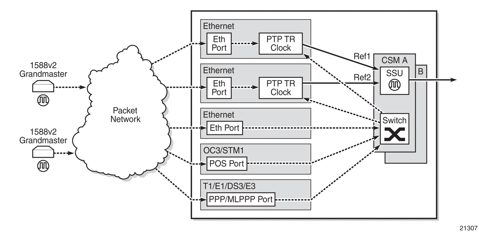
Each PTP ordinary timeReceiver clock is configured for a specific slot where the card (see IEEE 1588v2 PTP Support per Card on the 7705 SAR-8 Shelf V2 and 7705 SAR-18 ) or Ethernet port (see IEEE 1588v2 PTP Support per Fixed Platform) performs the timeReceiver function. On the 7705 SAR-M, 7705 SAR-H, 7705 SAR-Hc, 7705 SAR-A, 7705 SAR-Ax, and 7705 SAR-Wx, this slot is always 1/1. On the 7705 SAR-X, this slot is always either 1/2 or 1/3. When the 7705 SAR-M is receiving PTP packets on the 2-port 10GigE (Ethernet) module, its PTP clock continues to use slot 1/1. Each timeReceiver is also associated with an IP interface on a specific port, adapter card, or loopback address for the router; however, the IP interface configured on a 2-port 10GigE (Ethernet) module cannot be associated with a timeReceiver clock.
For best performance, the network should be designed so that the IP messaging between the timeTransmitter clock and the timeReceiver clock ingresses and egresses through a port where the timeReceiver is configured. If the ingress and egress flow of the PTP messages is via a different port or adapter card on the 7705 SAR, then the packets are routed through the fabric to the Ethernet card with the PTP timeReceiver.
It is possible that the PTP IP packets may be routed through another Ethernet port/VLAN, OC3/STM1 or OC12/STM4 clear channel POS, OC3/STM1 or OC12/STM4 channelized MLPPP, DS3/E3 PPP, or DS1/E1 MLPPP. The PTP timeReceiver performance may be slightly worse in this case because of the extra PDV experienced through the fabric. Packets are routed this way only if the clock is configured with a loopback address. If the clock is configured with an address tied to a physical port, the packets arrive on that physical port as described above.
PTP Ordinary TimeTransmitter Clock For Frequency
The 7705 SAR supports the PTP ordinary clock in timeTransmitter mode. Normally, a 1588v2 grandmaster is used to support many timeReceivers and boundary clocks in the network. In cases where only a small number of timeReceivers and boundary clocks exist and only frequency is required, a PTP integrated timeTransmitter clock can greatly reduce hardware and management costs to implement PTP across the network. It also provides an opportunity to achieve better performance by placing a timeTransmitter clock deeper into the network, as close to the timeReceiver clocks as possible.
The following figure shows a PTP timeTransmitter clock network configuration.
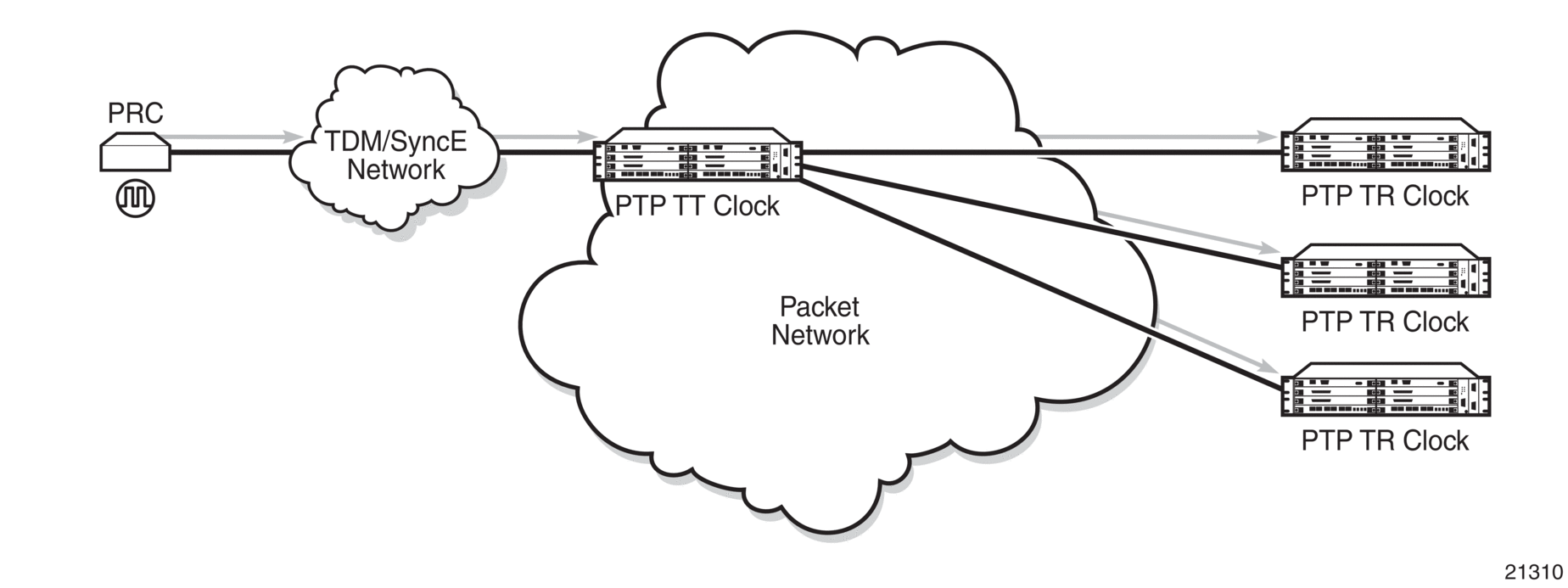
The PTP timeTransmitter clock capability is implemented on the Ethernet ports of the platforms listed in IEEE 1588v2 PTP Support per Fixed Platform and on the cards listed in IEEE 1588v2 PTP Support per Card on the 7705 SAR-8 Shelf V2 and 7705 SAR-18 .
The 7705 SAR-8 Shelf V2 can support up to six timeTransmitter clocks and the 7705 SAR-18 can support up to eight timeTransmitter clocks. The fixed platforms listed in IEEE 1588v2 PTP Support per Fixed Platform can each support one timeTransmitter clock.
The following figure shows the operation of an ordinary PTP clock in timeTransmitter mode.
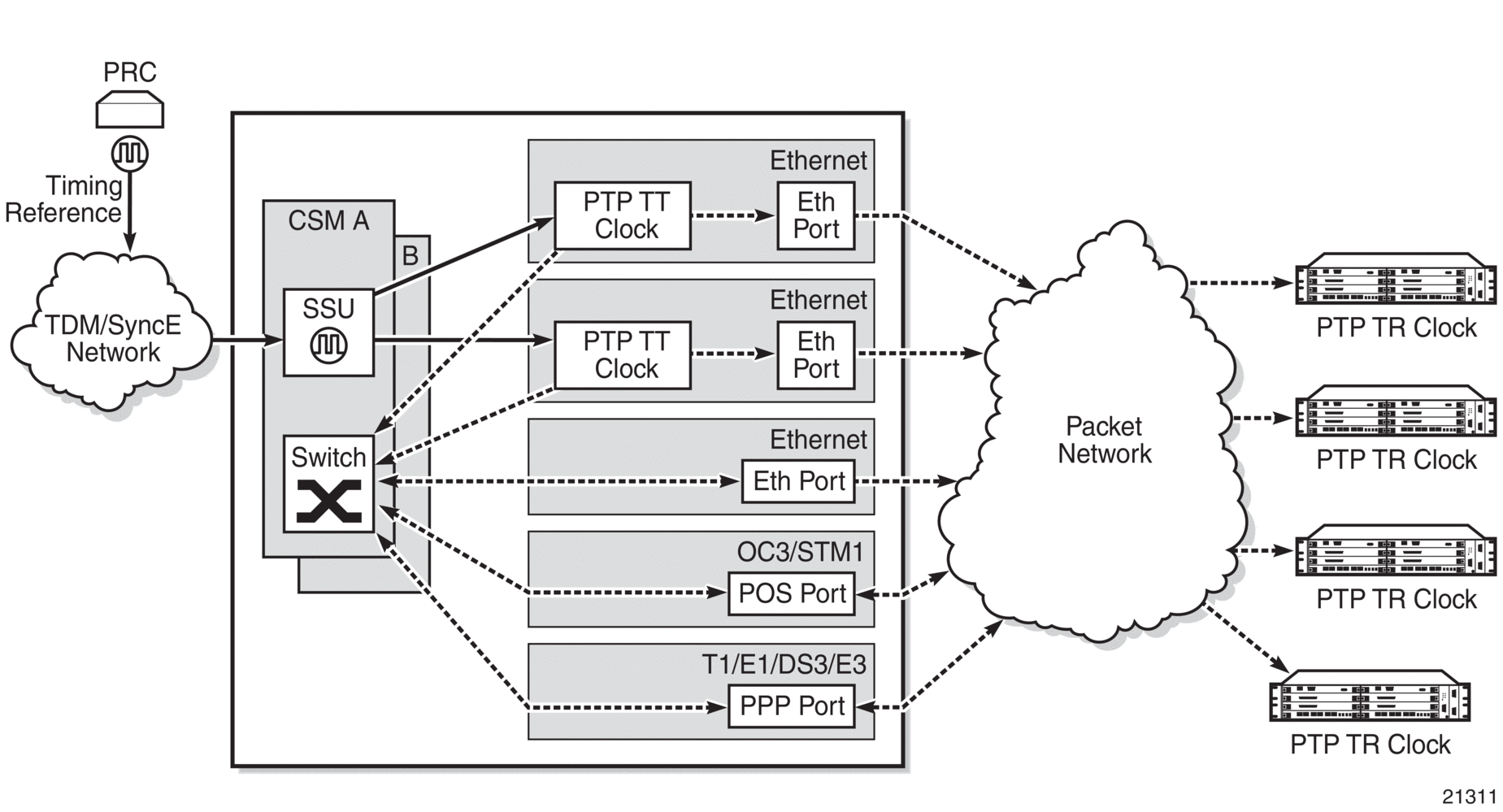
Each PTP timeTransmitter clock is configured for a specific slot where the card (see IEEE 1588v2 PTP Support per Card on the 7705 SAR-8 Shelf V2 and 7705 SAR-18 ) or Ethernet port (see IEEE 1588v2 PTP Support per Fixed Platform) performs the timeTransmitter function. On the 7705 SAR-M, 7705 SAR-H, 7705 SAR-Hc, 7705 SAR-A, 7705 SAR-Ax, and 7705 SAR-Wx, this slot is always 1/1. On the 7705 SAR-X, this slot is always either 1/2 or 1/3. When the 7705 SAR-M is receiving PTP packets on a 2-port 10GigE (Ethernet) module, its PTP clock continues to use slot 1/1. Each timeTransmitter is also associated with an IP interface on a specific port, adapter card, or loopback address for the router; however, the IP interface configured on a 2-port 10GigE (Ethernet) module cannot be associated with a timeTransmitter clock. All packets that ingress or egress through a port where the timeTransmitter is configured are routed to their destination via the best route as determined in the route table.
Each timeTransmitter clock can peer with up to 50 timeReceivers or boundary clocks. The IP addresses of these peers can be statically configured via CLI or dynamically accepted via PTP signaling messages. A statically configured peer may displace a dynamic peer on a particular PTP port. If there are fewer than 50 peers, then that dynamic peer can signal back and be granted a different PTP-port instance.
PTP Boundary Clock For Frequency
The 7705 SAR supports boundary clock PTP devices in both timeTransmitter and timeReceiver states. IEEE 1588v2 can function across a packet network that is not PTP-aware; however, the performance may be unsatisfactory and unpredictable. PDV across the packet network varies with the number of hops, link speeds, usage rates, and the inherent behavior of the routers. By using routers with boundary clock functionality in the path between the grandmaster clock and the timeReceiver clock, one long path over many hops is split into multiple shorter segments, allowing better PDV control and improved timeReceiver performance. This allows PTP to function as a valid timing option in more network deployments and allows for better scalability and increased robustness in specific topologies, such as rings.
Boundary clocks can simultaneously function as a PTP timeReceiver of an upstream grandmaster (ordinary clock) or boundary clock, and as a PTP timeTransmitter of downstream timeReceivers (ordinary clocks) or boundary clocks. The following figure shows the operation of a boundary clock.
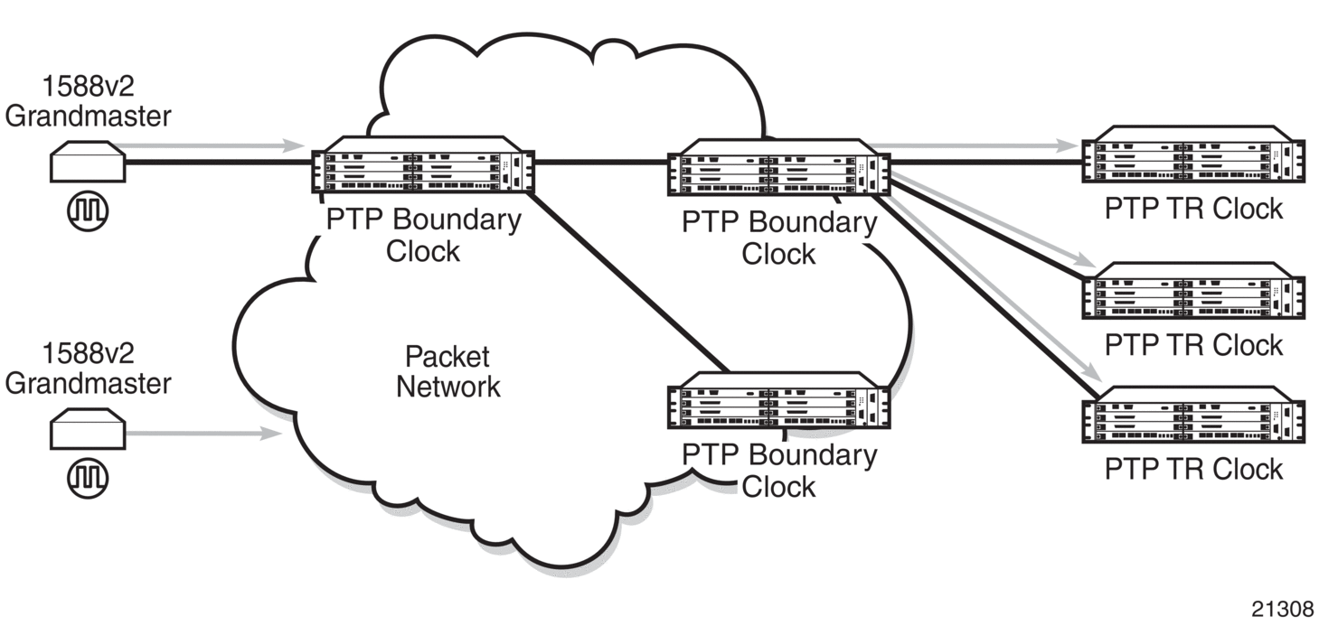
The PTP boundary clock capability is implemented on the Ethernet ports of the platforms listed in IEEE 1588v2 PTP Support per Fixed Platform and on the cards listed in IEEE 1588v2 PTP Support per Card on the 7705 SAR-8 Shelf V2 and 7705 SAR-18 .
The 7705 SAR-8 Shelf V2 can support up to six boundary clocks and the 7705 SAR-18 can support up to eight boundary clocks. The fixed platforms listed in IEEE 1588v2 PTP Support per Fixed Platform can each support one boundary clock.
Each PTP boundary clock is configured for a specific slot where the card (see IEEE 1588v2 PTP Support per Card on the 7705 SAR-8 Shelf V2 and 7705 SAR-18 ) or Ethernet port (see IEEE 1588v2 PTP Support per Fixed Platform) performs the boundary clock function. On the 7705 SAR-M, 7705 SAR-H, 7705 SAR-Hc, 7705 SAR-A, 7705 SAR-Ax, and 7705 SAR-Wx, this slot is always 1/1. On the 7705 SAR-X, this slot is always either 1/2 or 1/3. When the 7705 SAR-M is receiving PTP packets on a 2-port 10GigE (Ethernet) module, its PTP clock continues to use slot 1/1. Each boundary clock is also associated with a loopback address for the router; however, the IP interface configured on a 2-port 10GigE (Ethernet) module cannot be associated with a boundary clock.
Each boundary clock can be peered with up to 50 timeReceivers, boundary clocks, or grandmaster clocks. The IP addresses of these peers can be statically configured via CLI or dynamically accepted via PTP signaling messages. A statically configured peer may displace a dynamic peer on a particular PTP port. If there are fewer than 50 peers, that dynamic peer can signal back and be granted a different PTP-port instance.
The following figure shows an example of boundary clock operation.
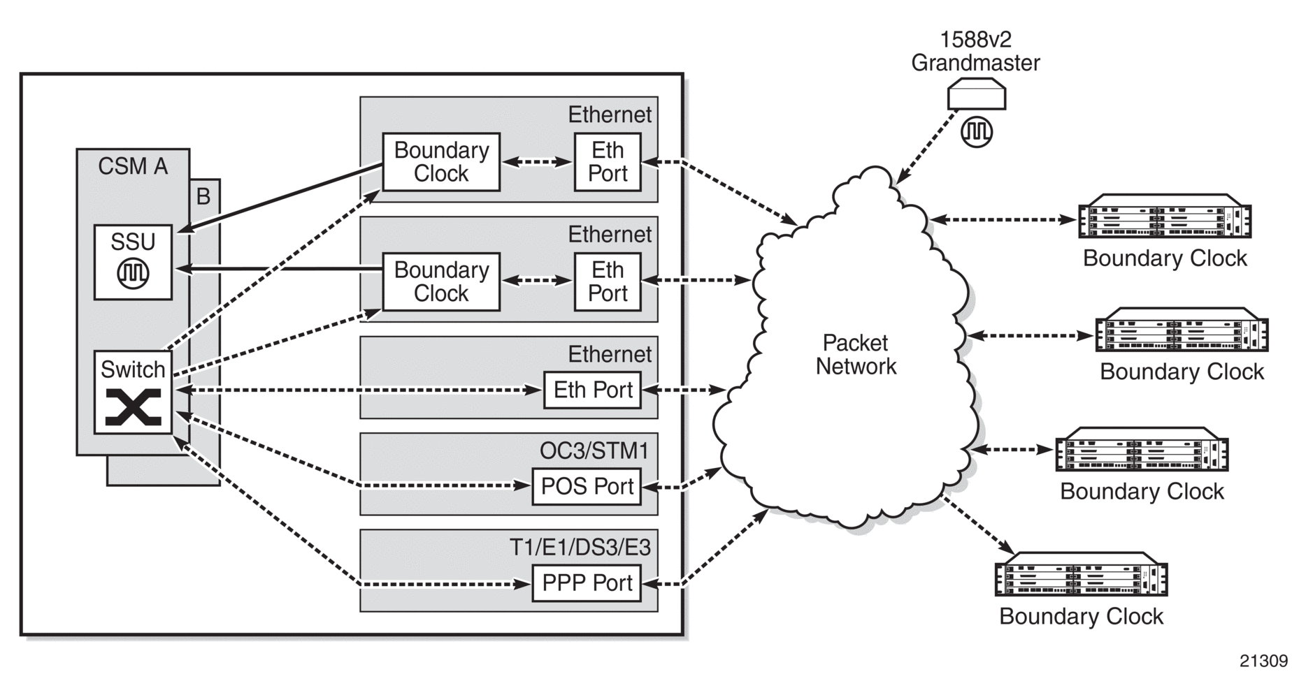
PTP Ordinary TimeReceiver Clock for Time of Day/Phase Recovery
The following equipment supports PTP timeReceiver clock for time of day/phase recovery:
-
all fixed platforms listed in IEEE 1588v2 PTP Support per Fixed Platform
-
all cards listed in IEEE 1588v2 PTP Support per Card on the 7705 SAR-8 Shelf V2 and 7705 SAR-18
The 7705 SAR can receive and extract time of day/phase recovery from a 1588 grandmaster clock or boundary clock and transmit the recovered time of day/phase signal to an external device such as a base station through an external time of day port, where available. The PTP timeReceiver clock can be used as a reference for the router system time clock, providing high-accuracy OAM timestamping and measurements for the 7705 SAR chassis.
On the 7705 SAR-8 Shelf V2 CSMv2, 7705 SAR-A, 7705 SAR-Ax, 7705 SAR-M, and 7705 SAR-X, transmission is through the ToD port with a 1 pulse/s output signal that is phase-aligned with other routers that are similarly time of day/phase synchronized. An RS-422 serial interface within the ToD port connector communicates the exact time of day of the rising edge of the 1 pulse/s signal. The serial interface on the ToD out port and the ToD in port on the CSMv2 are currently not supported; therefore, the 7705 SAR-8 Shelf V2 does not support Time of Day messages.
On the 7705 SAR-H, transmission is through the IRIG-B Out port. An RJ45 interface is used for the IRIG-B Out port to communicate the exact time of day by the rising edge of the 1 pulse/s signal, an IRIG-B000 unmodulated time code signal, and an IRIG-B12X modulated time code signal.
On the 7705 SAR-H, the Time of Day message output is only available when the router is configured with an active IP PTP timeReceiver clock or boundary clock. For all other routers, the Time of Day message output is available when the router is configured with an active IP PTP timeReceiver clock or boundary clock or when Time of Day is recovered from an Ethernet PTP clock or integrated GNSS.
The following table lists the 1 pulse/s signal (1pps) support and Time of Day messaging support per platform.
|
1pps Out |
ToD Messages Out |
1pps In |
ToD Messages In |
|
|---|---|---|---|---|
|
7705 SAR-8 Shelf V2 CSMv2 |
Yes |
No |
No |
No |
|
7705 SAR-A |
Yes |
Yes for IP PTP Yes for Ethernet PTP |
No |
No |
|
7705 SAR-Ax |
Yes |
Yes for IP PTP Yes for Ethernet PTP |
No |
No |
|
7705 SAR-H |
Yes |
Yes for IP PTP No for Ethernet PTP |
No |
No |
|
7705 SAR-M |
Yes |
Yes for IP PTP Yes for Ethernet PTP |
No |
No |
|
7705 SAR-X |
Yes |
Yes for IP PTP Yes for Ethernet PTP |
No |
No |
The following table describes the format of the ToD message.
|
Byte Offset |
Length |
Field Name |
Description |
|---|---|---|---|
|
0 |
4 |
Second time of week |
The GPS time of week, in seconds |
|
4 |
4 |
Reserved |
n/a |
|
8 |
2 |
Week |
The GPS week (GPS time) |
|
10 |
1 |
LeapS |
Leap seconds (GPS-UTC) |
|
11 |
1 |
1PPS status |
The 1pps signal value: 1
|
|
12 |
1 |
TAcc |
The jitter level of 1PPS. This field is currently not in use. |
|
13 |
1 |
Reserved |
n/a |
|
14 |
1 |
Reserved |
n/a |
|
15 |
1 |
Reserved |
n/a |
Note:
- Enhanced ToD 1pps values are not supported on the 7705 SAR-H.
For incoming IEEE 1588 packets, the destination IP address is the 7705 SAR-M, 7705 SAR-H, 7705 SAR-Hc, 7705 SAR-A, 7705 SAR-Ax, 7705 SAR-Wx, or 7705 SAR-X loopback address. The ingress interface can be an SFP Ethernet port on the faceplate of the chassis, an RJ45 port on the faceplate of the chassis, or a port on an installed module.
Each PTP timeReceiver clock can be configured to receive timing from up to two PTP timeTransmitter clocks in the network. If both timeTransmitter clocks are available, the timeReceiver clock uses default BTCA to determine which of the two timeTransmitter clocks it should synchronize.
PTP messaging between the PTP timeTransmitter clock and PTP timeReceiver clock is done over UDP/IP using IPv4 unicast mode with a fixed IP header size or using IPv6. Unicast negotiation is supported. Each PTP instance supports up to 128 synchronization messages per second.
PTP recovered time accuracy depends on the delay of the forward path and the reverse path being symmetrical. It is possible to correct for known path delay asymmetry by using the ptp-asymmetry command for PTP packets destined for the local timeReceiver clock or downstream PTP timeReceiver clock.
PTP Boundary Clock for Time of Day/Phase Recovery
The following equipment supports PTP boundary clock capability for time of day/phase recovery:
all fixed platforms listed in IEEE 1588v2 PTP Support per Fixed Platform
all cards listed in IEEE 1588v2 PTP Support per Card on the 7705 SAR-8 Shelf V2 and 7705 SAR-18
The 7705 SAR-8 Shelf V2 can support up to six boundary clocks and the 7705 SAR-18 can support up to eight boundary clocks. The fixed platforms can each support one boundary clock. PTP boundary clocks that recover time of day/phase from a grandmaster clock or another boundary clock can be used as a reference for the router system time clock, providing high-accuracy OAM timestamping and measurements for the 7705 SAR chassis.
Each PTP boundary clock for time of day/phase is configured for a specific slot where the adapter card or port performs the boundary clock function. On fixed platforms, with the exception of the 7705 SAR-X, this slot is always 1/1. On the 7705 SAR-X, this slot is always either 1/2 or 1/3. Each boundary clock is also associated with a loopback or system address for the router.
PTP End-to-End Transparent Clock for Time of Day/Phase Recovery
PTP end-to-end transparent clock for time of day/phase recovery is supported on the following:
the fixed platforms listed in IEEE 1588v2 PTP Support per Fixed Platform
2-port 10GigE (Ethernet) module
Transparent clock functionality is supported for PTP packets over UDP/IP over Ethernet (with and without VLAN tags).
For high-accuracy 1588 PTP clock recovery, timestamping of incoming and outgoing messages should be done as close to ingress and egress as possible when the 7705 SAR is acting as a 1588 transparent clock. Edge timestamping is performed on all packets from all Ethernet ports, including SFP and RJ45 ports on the faceplate of the chassis or a port on an installed module.
PTP recovered time accuracy depends on the delay of the forward path and the reverse path being symmetrical. It is possible to correct for known path delay asymmetry by using the ptp-asymmetry command to configure an asymmetry delay setting in nanoseconds per direction for each edge.
To enable transparent clock processing at the node level, configure a PTP clock with the transparent-e2e clock type (using the clock-type command). Deconfiguring such a PTP clock disables transparent clock processing.
PTP TimeTransmitter Clock for Time of Day/Phase Distribution
PTP timeTransmitter clock capability for time of day/phase distribution is implemented on the following platforms:
7705 SAR-H with a GPS Receiver module
7705 SAR-Wx variants with a GPS RF port
7705 SAR-8 Shelf V2 with a GNSS Receiver card
7705 SAR-18 with a GNSS Receiver card
Time of day input must be enabled using the use-node-time command before the node can be used as a PTP grandmaster clock. GNSS must also be the active system time reference for nodes that are being used as a grandmaster clock. When the use-node-time command is enabled, the PTP timeTransmitter clock uses the system time as a source of PTP time and can be used for time of day/phase distribution. When the use-node-time command is disabled, the PTP timeTransmitter clock can be used for frequency only.
PTP Clock Redundancy
Each PTP timeReceiver clock can be configured to receive timing from up to two PTP timeTransmitter clocks. If two PTP timeTransmitter clocks are configured, and if communication to the best timeTransmitter is lost or if the BTCA determines that the other PTP timeTransmitter clock is better, then the PTP timeReceiver clock switches to the other PTP timeTransmitter clock.
For a redundant or simple CSM configuration on the 7705 SAR-8 Shelf V2 and 7705 SAR-18, a maximum of two PTP timeReceiver clocks can be configured as the source of reference (ref1 and ref2) to the SSU. If a failure occurs between the PTP timeReceiver clock and the timeTransmitter clock, the SSU detects that ref1 or ref2 is unavailable and automatically switches to the other reference source. This switching provides PTP hot redundancy for hardware failures (on the 6-port Ethernet 10Gbps Adapter card, 8-port Gigabit Ethernet Adapter card, 10-port 1GigE/1-port 10GigE X-Adapter card, or Packet Microwave Adapter card) or port or facility failures (SFP or cut fiber). If a loopback address is used, PTP packets may arrive on any router network interface and the PTP clock remains up.
The 7705 SAR-M, 7705 SAR-H, 7705 SAR-Hc, 7705 SAR-A, 7705 SAR-Ax, 7705 SAR-Wx, and 7705 SAR-X support only one PTP timeReceiver clock. This timeReceiver clock can be configured as the source of reference (ref1 or ref2) to the SSU.
PTP Ethernet Capabilities
The 7705 SAR can be configured to transmit and receive PTP messages over a port that uses Ethernet encapsulation. The encapsulation type can be null, dot1q, or qinq. Ethernet-encapsulated PTP messages are processed on the node CSM or CSM functional block, and they are supported on ordinary timeReceiver, ordinary timeTransmitter, or boundary clocks for either frequency or time of day/phase recovery. The 7705 SAR-Ax can also support a grandmaster clock. The 7705 SAR-H, 7705 SAR-Wx, 7705 SAR-8 Shelf V2, and 7705 SAR-18 can also support a grandmaster clock when equipped to support GNSS. A PTP clock using Ethernet encapsulation can support up to 50 external peer clocks.
All platforms and cards that support PTP functionality support Ethernet-encapsulated PTP messages, except for the 2-port 10GigE (Ethernet) Adapter card/module . See IEEE 1588v2 PTP Support per Fixed Platform and IEEE 1588v2 PTP Support per Card on the 7705 SAR-8 Shelf V2 and 7705 SAR-18 for a complete list of supported platforms and cards.
Ethernet encapsulation is configured on a -port basis using the config>system> ptp>clock command, with the clock-id parameter set to csm. Ports can simultaneously support IPv4-encapsulated or IPv6-encapsulated PTP messages and Ethernet-encapsulated PTP messages. As well, the 7705 SAR supports the interworking of a PTP timeReceiver using IPv4-encapsulated or IPv6-encapsulated messages with a PTP timeTransmitter using Ethernet-encapsulated messages.
When a PTP clock is configured for Ethernet encapsulation, the following profiles are available:
ieee1588-2008
g8275dot1-2014
iec-61850-9-3-2016
c37dot238-2017
The following table describes the supported message rates for timeReceiver and timeTransmitter states for Ethernet-encapsulated PTP traffic, based on the profile configured. The ordinary clock can be either in the timeReceiver or timeTransmitter state. The boundary clock can be in both of these states.
ieee1588-2008 |
g8275dot1-2014 |
iec-61850-9-3-2016 c37dot238-2017 |
||
|---|---|---|---|---|
Announce |
Minimum rate |
1 per 16 seconds |
1 per 16 seconds |
1 per 16 seconds |
Maximum rate |
8 per second |
8 per second |
8 per second |
|
Default rate |
1 per 2 seconds |
8 per second |
1 per second |
|
Sync |
Minimum rate |
1 per second |
1 per second |
1 per second |
Maximum rate |
64 per second |
64 per second |
64 per second |
|
Default rate |
64 per second |
16 per second |
1 per second |
|
Delay |
Minimum rate |
1 per second |
1 per second |
1 per second |
Maximum rate |
64 per second |
64 per second |
64 per second |
|
Default rate |
64 per second |
16 per second |
1 per second |
|
See Rates for IP-Encapsulated PTP Messages for the supported message rates for IP-encapsulated PTP traffic.
PTP messages are transported within Ethernet frames with the Ethertype set to 0X88F7. Ports can be configured with one of two reserved multicast destination addresses:
01-1B-19-00-00-00 — used for all PTP messages except for peer delay mechanism messages
01-80-C2-00-00-0E — used for peer delay mechanism messages
Either address can be used for all messages depending on customer requirements. See Recommendation ITU-T G.8275.1/Y.1369.1. When the profile configuration is iec-61850-9-3-2016 or c37dot238-2017, the 01-80-C2-00-00-0E address must be used for peer delay. See IEC/IEEE 61850-9-3 and the C37.238-2017 extension.
When the profile configuration is ieee1588-2008, iec-61850-9-3-2016, or c37dot238-2017, the PTP clock’s priority1 and priority2 settings are used by the BTCA to help determine which clock should provide timing for the network. When the profile configuration is g8275dot1-2014, the local-priority value is used to choose between PTP timeTransmitters in the BTCA.
ITU-T G.8275.1 and G.8275.2
The 7705 SAR supports Recommendation ITU-T G.8275.1 and Recommendation ITU-T G.8275.2, which specify the architecture that allows the distribution of time and phasing. ITU-T G.8275.1 supports full timing support from the network and ITU G.8275.2 supports partial timing support (PTS) and assisted partial timing support (APTS). If a PTP clock is configured for G.8275.2 without GNSS, it uses PTS; if it is configured for GNSS, it can use APTS. It is assumed that these profiles will be used in well-planned cases where network behavior and performance can be constrained within well-defined limits, including limits on static asymmetry. When configured for the G.8275.1 or G.8275.2 profile, the 7705 SAR can operate as a boundary clock, an ordinary timeTransmitter clock, or an ordinary timeReceiver clock.
When the 7705 SAR is configured for the G.8275.1 or G.8275.2 profile, it uses an alternate BTCA for best timeTransmitter clock selection. This BTCA includes a PTP dataset comparison that is defined in IEEE 1588-2008, but with the following differences:
the priority1 attribute value is removed from the dataset comparison
the master-only parameter value must be considered
multiple active grandmaster clocks are allowed; therefore, the BTCA will select the nearest clock of equal quality
a port-level local-priority attribute value is used to select a timeReceiver port if two ports receive an Announce message. This attribute is used as a tiebreaker in the dataset comparison algorithm if all other previous attributes of the datasets being compared are equal.
the local-priority parameter value is considered for the default dataset
The ITU-T G.8275.1 and G.8275.2 profiles have the following characteristics:
The default domain setting is 24 for G.8275.1; the allowed range is 0 to 255.
The default domain setting is 44 for G.8275.2; the allowed range is 0 to 255.
Both one-step and two-step clocks are supported on timeReceiver-capable PTP ports.
G.8275.2 supports IP encapsulation.
G.8275.1 supports IP encapsulation and Ethernet encapsulation. When Ethernet encapsulation is used, the following points apply:
Ethernet multicast addressing is used for transmitting PTP messages. Both the non-forwardable multicast address 01-80-C2-00-00-0E and forwardable multicast address 01-1B-19-00-00-00 are supported.
Virtual local area network (VLAN) tags within Ethernet frames carrying PTP messages are not supported. When a PTP clock receives a PTP message within a frame containing a VLAN tag, it discards this frame. A PTP clock that is compliant with the profile described in Recommendation ITU-T G.8275.1 must comply with IEEE 1588 – 2008 Annex F.
Synchronization messages are sent at a rate of 16 packets/s; Announce messages are sent at a rate of 8 packets/s.
On the 7705 SAR, the priority1 value is set to the default value (128) and cannot be changed.
On the 7705 SAR, if the clock-type parameter is set to ordinary slave, the priority2 value is set to the default value (255) and cannot be changed.
For further details, see Recommendation ITU-T G.8275.1/Y.1369.1 and Recommendation ITU-T G.8275.2/Y.1369.2.
ITU-T G.8275.2 APTS with Asymmetry Compensation
The ITU-T G.8275.2 APTS functionality is supported on the 7705 SAR-8 Shelf V2 and the 7705 SAR-18 when equipped with a GNSS Receiver card and two Ethernet adapter cards — one configured as a G.8275.2 timeReceiver clock for backup and one configured as a G.8275.2 boundary clock with timeTransmitter ports.
When the PTP clock is configured to use the G.8275.2 profile and the integrated GNSS is configured and operationally up, GNSS is the active reference for both time/phase and frequency for the system. For extra resilience, APTS can be deployed when the following conditions are met:
- a G.8275.2 timeReceiver clock (an IP PTP clock 1 to 8) is configured on an Ethernet adapter card for IP-encapsulated PTP and apts-asymmetry-compensation is enabled
- a G.8275.2 boundary clock (a different IP PTP clock 1 to 8) is configured on another Ethernet adapter card for IP-encapsulated PTP
- the synchronous equipment timing source (SETS) is configured for GNSS as the first preference using the config>system>sync-if-timing>ref1 command, PTP is configured as the second preference using the config>system>sync-if-timing>ref2 command, and the config>system>sync-if-timing>ref-order command is configured to set the timing priority; in addition, SETS must be configured for revertive switching using the config>system>sync-if-timing>revert command
- the time clock is configured with GNSS as the first preference and the PTP backup clock as the second preference
Even though GNSS is the active reference, the backup timeReceiver PTP port has an active session with an upstream PTP grandmaster clock through a non-PTP network.
When GNSS is up, the level of asymmetry on the designated backup timeReceiver clock is monitored when the apts-asymmetry-compensation command is enabled. The CSM notes the time and frequency recovery state and the delay asymmetry of the backup timeReceiver clock based on the timestamps exchanged during the last update. If GNSS fails, the measured level of asymmetry is applied to the PTP backup clock to keep time and phase as accurate as possible. The monitored states and values are available via the CLI and SNMP.
The following table is from Recommendation ITU-T G.8275.2/Y.1369.2 (11/2022). It describes the mapping between the ITU-T G.8275.2 and PTP clock types. T-BC-A and T-TSC-A clocks apply to APTS.
| Clock Type from ITU-T G.8275.2 | Description | Clock Type from IEEE 1588 |
|---|---|---|
| T-GM |
timeTransmitter ordinary clock (clock with a single PTP port; cannot be a timeReceiver from another PTP clock) |
Ordinary clock |
|
timeTransmitter boundary clock (clock with multiple PTP ports; cannot be a timeReceiver from another PTP clock) |
Boundary clock1 |
|
| T-BC-P (partial) |
Boundary clock (may become a grandmaster clock or may be a timeReceiver from another PTP clock) |
Boundary clock |
| T-BC-A (assisted partial) |
Boundary clock assisted by a local time reference that is used as a primary source of time (may become a grandmaster clock or may be a timeReceiver to another PTP clock) |
Boundary clock2 |
| T-TSC-P (partial) | Always timeReceiver; single-port ordinary clock | Ordinary clock |
|
PTP clock at the end of the PTP synchronization chain; multiple port clock |
Boundary clock1 | |
| T-TSC-A (assisted partial) |
Always timeReceiver; single-port ordinary clock assisted by a local time reference that is used as a primary source of time |
Ordinary clock2 |
|
PTP clock at the end of the PTP synchronization chain; multiple-port clock assisted by a local time reference that is used as a primary source of time |
Boundary clock1, 2 |
Notes:
- According to IEEE 1588, a clock that has multiple PTP ports is by definition a boundary clock.
- Examples of local time references are a PRTC or a GNSS-based time source.
GNSS Failure and Recovery with APTS
When the G.8275.2 profile is used for GNSS-enabled 7705 SAR platforms, the APTS function frequently measures and stores the delay offset between the GNSS time and a backup PTP session time.
If GNSS fails, the time and frequency reference automatically switches from GNSS to the backup PTP timeReceiver clock, and the stored delay offset value is added to or subtracted from the backup PTP session to keep time and phase for the router as accurate as possible. After switching to the backup PTP timeReceiver clock, the clockClass output from the boundary clock corresponds to the clockClass from the backup PTP parent clock. If the clockClass of the parent clock is 6, the clockClass output of the boundary clock is 6 throughout the time reference switch operation.
When GNSS recovers after a failure, the boundary clock time reference switches back to GNSS from the backup PTP timeReceiver clock. Assuming that the asymmetry from the backup PTP has remained constant, the time to switch to the downstream clocks is minimal.
The switch back to GNSS must wait until GNSS time recovery stabilization is complete. After switching back to GNSS, the output clockClass of the boundary clock should be 6. If the backup PTP parent clock was also 6, the clockClass output of the boundary clock is 6 throughout the time reference switch operation.
If a failure occurs and neither GNSS nor the PTP backup is available, the PTP boundary clock enters holdover. The clockClass output from the boundary clock is 165.
For information about the values for the clockClass, time traceable flag, and frequency traceable flag, see Table 3 in Recommendation ITU-T G.8275.2/Y.1369.2 (11/2022).
Synchronization Certainty/Uncertainty
As described in Best TimeTransmitter Clock Algorithm, timeTransmitter clocks transmit Announce messages containing the clock priority and quality. Each clock in the network can use the BTCA and the clock properties received from the Announce messages to select the best clock to synchronize to.
Within a PTP-aware network, there could be situations where boundary clocks advertise clockClass 6 in the Announce message, which indicates that the parent clock is connected to a traceable primary reference source/clock (PRS/PRC) in locked mode (for example, locked to GNSS), and is therefore designated as the synchronization time source. However, the PTP network may still be in a transient state and stabilizing.
For example, this may occur when:
a grandmaster clock locks and relocks to GNSS
an intermediate boundary clock is started or restarted
a new parent clock is chosen
Depending on the application, it may be important for a downstream boundary clock or timeReceiver clock to know whether the PTP network has stabilized or is still ‟synchronization uncertain”.
Specifically when the G.8275.1profile (with IP encapsulation) or the G.8275.2 profile is used, the synchronizationUncertain flag is added to the Announce message. The use of this flag is optional. The 7705 SAR PTP grandmaster, boundary, and timeReceiver clocks support the processing of the synchronization state as follows.
If a grandmaster clock has its synchronous equipment timing source (SETS) frequency clock and time clock locked to GNSS and its clockClass equals 6, it is in a ‟synchronization certain” state. The synchronizationUncertain flag in the Announce message is set to FALSE.
If a grandmaster clock does not meet the above criteria, it is in a ‟synchronization uncertain” state. The synchronizationUncertain flag in the Announce message is set to TRUE.
In order for a boundary clock to be in the ‟synchronization certain” state, its parent clock’s clockClass must be ‟synchronization certain”, its SETS must be locked and PRS/PRC traceable, and PTP must have sufficient time to stabilize to the parent clock. At that point, its PTP port state transitions from an Uncalibrated state to a TimeReceiver state.
The transition period is 16 s for G.8275.1 and 256 s for G.8275.2. To be selected as a system time reference, a G.8275.1 or G.8275.2 clock must be in the ‟synchronization certain” state.
A boundary clock can fall back to the ‟synchronization uncertain” state if its parent clock changes to the ‟synchronization uncertain” state, its SETS becomes unlocked or not PRS/PRC traceable, or the local clock is restarted or reset. The PTP port state transitions away from the TimeReceiver state.
This behavior is shown in the following figure.
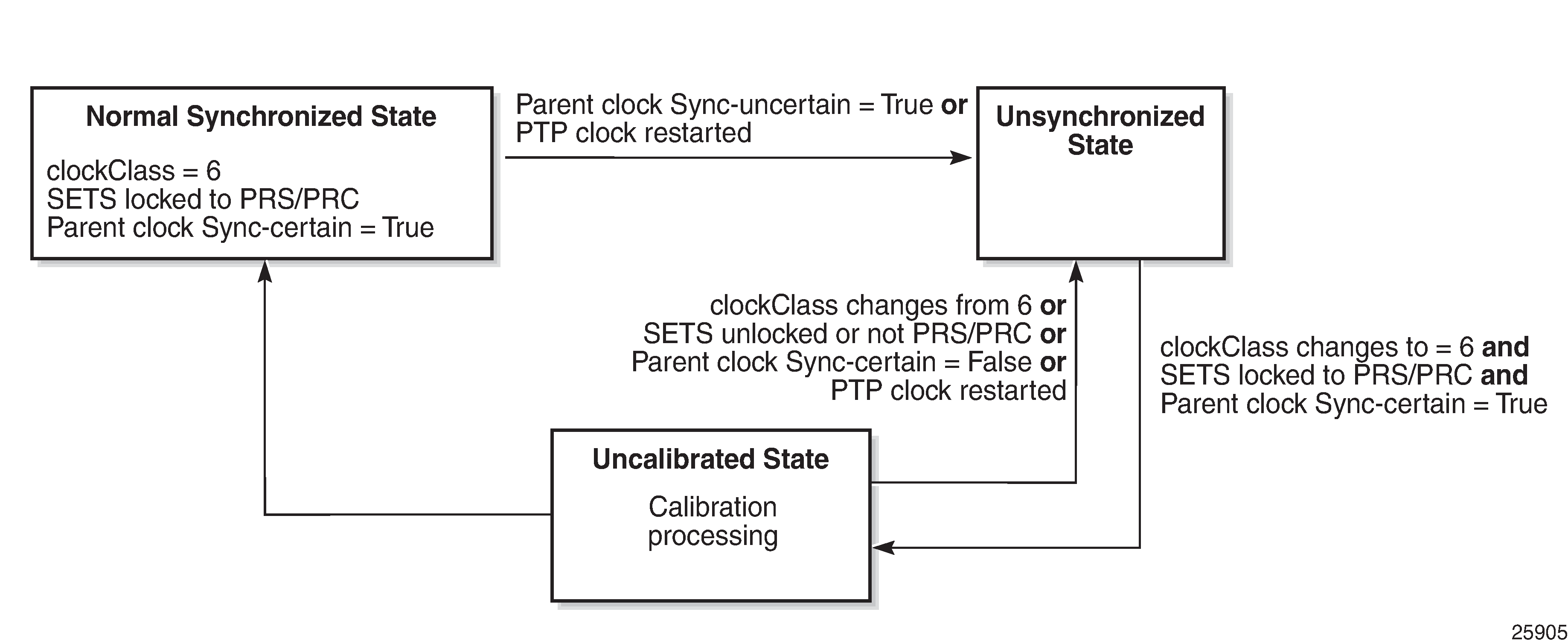
Because the synchronizationUncertain flag is newly agreed upon in standards, most base station timeReceiver clocks do not look at this bit. Therefore, in order to ensure that the downstream clocks are aware of the state of the network, the PTP clock (grandmaster, boundary, timeReceiver) may optionally be configured to transmit Announce and Sync messages only if the clock is in a ‟synchronization certain” state. This is done using the no tx-while-sync-uncertain command.
IEC/IEEE 61850-9-3 and C37.238-2017
The 7705 SAR supports IEC/IEEE 61850-9-3 and the C37.238-2017 extension, which are profiles that allow PTP to act as a timing source in power utility networks.
The IEC/IEEE 61850-9-3 and C37.238-2017 profiles support only Ethernet encapsulation with multicast addressing. Both profiles use the peer delay mechanism instead of the delay-request/response mechanism.
When configured for IEC/IEEE 61850-9-3 or C37.238-2017, the 7705 SAR can operate as a grandmaster clock, a boundary clock, or an ordinary timeReceiver clock and supports recovery of frequency as well as time of day/phase. Grandmaster clock functionality is only available for 7705 SAR variants with integrated GNSS.
Synchronous Ethernet can be used for frequency recovery as an optional mode for best time/phase recovery.
The IEC/IEEE 61850-9-3 and C37.238-2017 profiles have the following characteristics.
The default domain setting is 0 for IEC/IEEE 61850-9-3 and 254 for C37.238-2017; the allowed range is 0 to 255.
One-step clock operation is supported, without the need for follow-up messages.
When Ethernet encapsulation is used, virtual local area network (VLAN) tags within Ethernet frames carrying PTP messages are not supported. When a PTP clock receives a PTP message within a frame containing a VLAN tag, it discards this frame.
Synchronization messages, Announce messages, and peer delay messages are sent, by default, at the rate of 1 packet/s.
By default, the priority1 and priority2 values are set to 255 when the clock type is ordinary timeReceiver and 128 when the clock type is ordinary timeTransmitter. The priority values can be configured to be between 0 and 255.
The C37.238-2017 profile uses the IEEE_C37_238 TLV in Announce messages between the parent and timeReceiver clocks. This TLV includes the grandmaster clock ID and the total time inaccuracy. Each clock in the chain adds its own inaccuracy to the total time inaccuracy, which gives the ultimate timeReceiver clock an estimate of the inaccuracy over the entire path.
The grandmaster inaccuracy includes the source time inaccuracy and the grandmaster time inaccuracy. When acting as a boundary clock, the system receives the total time inaccuracy from the parent clock and adds its own time inaccuracy, then sends out a TLV with the updated total time inaccuracy. By default, the time inaccuracy value is 100 ns for a grandmaster clock and 50 ns for a boundary clock. The default value can be changed for a boundary clock with the time-inaccuracy-override command.
For further details, see the IEC/IEEE 61850-9-3 standard and the C37.238-2017 extension.
PTP Profile Interworking
The PTP profile interworking feature allows the 7705 SAR to interwork a primary PTP profile with ports using alternate profiles connected to external devices. The 7705 SAR supports single-clock and multi-clock PTP profile interworking.
Single-clock PTP Profile Interworking
Single-clock PTP profile interworking allows the 7705 SAR to use G.8275.1 as a primary PTP profile while interworking with ports using alternate profiles connected to external devices. The profiles must support Ethernet encapsulation. The 7705 SAR supports one primary profile for interworking, which must be configured as G.8275.1, and up to two alternate profiles, which can be configured as either IEC/IEEE 61850-9-3 or C37.238-2017.
By default, all PTP ports use the primary profile. The port must be shut down before the profile configuration can be modified. Any port that uses an alternate profile must be shut down before the alternate profile configuration can be modified.
Only messages exchanged on interfaces using the primary profile are included in the BTCA for the PTP clock. Interfaces using an alternate profile are considered to have their master-only value set to true and ignore any Announce messages they receive.
The PTP clock follows the BTCA rules of the primary profile and updates all datasets appropriately. Interfaces using an alternate profile use the datasets of the PTP clock to populate fields in PTP messages. However, some values from the primary profile are modified because they are incompatible with values expected by the alternate profiles. The message rates used for the Announce messages may differ between profiles. The Announce rate is controlled by the log-anno-interval command configured for the profile in use. The Sync and Delay message rates are controlled by the per-port configuration.
The clockClass value in the Announce message may need to be converted (as shown in the following table) when interworking from a G.8275.1 primary profile to either the IEC/IEEE 61850-9-3 or C37.238-2017 alternate profile.
| From Primary Profile | To Alternate Profile |
|---|---|
6 |
6 1 |
7 |
7 |
All other values |
187 2 |
Notes:
- For normal-locked, time-traceable, and frequency-traceable
- After the loss of time reference signal, when the time error exceeds 1 μs
See IEC/IEEE 61850-9-3 and C37.238-2017 for more information about these profiles.
Multi-clock PTP Profile Interworking
Multi-clock PTP profile interworking allows the 7705 SAR to interwork multiple PTP profile combinations with a mix of IP and Ethernet encapsulations. With multi-clock PTP profile interworking, there are two active PTP clocks in the system: one PTP clock with Ethernet encapsulation (clock-id parameter set to csm) and one PTP clock with IP encapsulation (clock-id parameter set to 1 to 12). Multi-clock interworking is supported on the 7705 SAR-8 and 7705 SAR-18 on 8-port Gigabit Ethernet Adapter cards and 6-port Ethernet 10Gbps Adapter cards.
To assign a clock profile to be the primary clock, configure the system time to recover time from its clock ID with the config>system>time>ptp>clock command. To assign a clock profile to be the alternate clock, enable the use-node-time command on its clock ID. The alternate clock uses the timing reference recovered from the primary profile clock.
If the Ethernet encapsulated clock is the primary clock (the main router clock), the IP encapsulated clock must be the alternate clock that uses the primary clock as reference. The reverse is true if the IP encapsulated clock is the primary clock.
If the node time clock is based on the integrated GNSS, both PTP clocks can be timeTransmitter clocks for their respective profiles. In this scenario, there is no profile interworking because there is no way to determine which clock is the primary clock and which is the alternate clock.
The primary clock can be a timeTransmitter, boundary, or timeReceiver. The alternate clock must be configured to be a timeTransmitter for multi-clock PTP profile interworking.
The supported profile combinations are:
primary profile is G.8275.2 (IP encapsulation) and alternate profile is G.8275.1 (Ethernet encapsulation)
primary profile is G.8275.2 (IP encapsulation) and alternate profile is IEC/IEEE 61850-9-3 (Ethernet encapsulation)
primary profile is G.8275.2 (IP encapsulation) and alternate profile is C37.238-2017 (Ethernet encapsulation)
primary profile is G.8275.1 (Ethernet encapsulation) and alternate profile is G.8275.2 (IP encapsulation)
The frequency reference used by the alternate PTP clock is based on the SETS configuration which can be the integrated GNSS, PTP, or any other acceptable frequency reference available on the 7705 SAR. G.8275.1 PTP is not a valid reference for frequency.
PTP Statistics
The 7705 SAR provides the capability to collect statistics, state, and events data for the PTP timeReceiver clock’s interaction with PTP peer clock 1 and PTP peer clock 2. This data is collected separately for each peer clock and can be displayed using the show system ptp clock ptp-port command. This data can be used to monitor the PTP timeReceiver clock performance in relation to the peer clocks and to diagnose a problem or analyze the performance of a packet switched network for the transport of synchronization messages. The following data is collected:
PTP peer-1/PTP peer-2 statistics:
number of signaling packets
number of unicast request announce packets
number of unicast request announce timeouts
number of unicast request announce packets rejected
number of unicast request synchronization packets
number of unicast request synchronization timeouts
number of unicast request synchronization packets rejected
number of unicast request delay response packets
number of unicast request delay response packets timeouts
number of unicast request delay response packets rejected
number of unicast grant announce packets
number of unicast grant announce packets rejected
number of unicast grant synchronization packets
number of unicast grant synchronization packets rejected
number of unicast grant delay response packets
number of unicast grant delay response packets rejected
number of unicast cancel announce packets
number of unicast cancel synchronization packets
number of unicast cancel delay response packets
number of unicast acknowledge cancel announce packets
number of unicast acknowledge cancel synchronization packets
number of unicast acknowledge cancel delay response packets
number of announce packets
number of synchronization packets
number of follow-up packets
number of delay response packets
number of delay request packets
number of out-of-order synchronization packets
total number of UDP (port 320) packets
total number of UDP (port 319) packets
number of alternate timeTransmitter packets discarded
number of bad domain packets discarded
number of bad version packets discarded
number of duplicate messages packets discarded
number of step RM greater than 255 discarded
PTP timeTransmitter-1/PTP timeTransmitter-2 algorithm state statistics (in seconds):
number of free-run states
number of acquiring states
number of phase-tracking states
number of hold-over states
number of locked states
PTP timeTransmitter-1/PTP timeTransmitter-2 algorithm event statistics:
number of excessive frequency errors detected
number of excessive packet losses detected
number of packet losses spotted
number of excessive phase shifts detected
number of high PDVs detected
number of synchronization packet gaps detected
Synchronous Ethernet
Synchronous Ethernet is a variant of line timing that derives the physical layer transmitter clock from a high-quality timing reference, traceable to a primary reference clock. Synchronous Ethernet uses the physical layer of the Ethernet link to distribute a common clock signal to all nodes in the network. Each node has a local or system clock that determines the outgoing clock rate of each interface. The system clock of each node in the network is derived from the incoming clock at an input interface or from a dedicated timing interface; for example, a BITS port.
Synchronous Ethernet works at Layer 1 and is concerned only with the precision of the timing of signal transitions to relay and recover accurate frequencies. It is not impacted by traffic load and is therefore not affected by packet loss or PDV that occurs with timing methods that use higher layers of the networking technology.
Synchronous Ethernet is automatically enabled on ports and SFPs that support synchronous Ethernet. The operator can select an Ethernet SFP port as a candidate timing reference. The recovered timing from this port is distributed to the nodes in the network over the physical layer of the Ethernet link. This allows the operator to ensure that any of the system outputs are locked to a stable, traceable frequency source. The transmit timing of all SFP ports with SFPs that support synchronous Ethernet is then derived from the node’s SSU.
Synchronous Ethernet can only be used for end-to-end network synchronization when all intermediate switching nodes in the network have hardware and software support for synchronous Ethernet.
Synchronous Ethernet is supported on the following cards and platforms:
6-port Ethernet 10Gbps Adapter card
8-port Gigabit Ethernet Adapter card
2-port 10GigE (Ethernet) Adapter card
2-port 10GigE (Ethernet) module
10-port 1GigE/1-port 10GigE X-Adapter card
Packet Microwave Adapter card
6-port SAR-M Ethernet module
7705 SAR-M (on all Ethernet ports)
7705 SAR-Hc (on all Ethernet ports)
7705 SAR-Wx (on all Ethernet ports)
7705 SAR-H (on all Ethernet ports)
7705 SAR-A (supported on the XOR ports (1 to 4), configured as either RJ45 ports or SFP ports, and on SFP ports 5 to 8. Ports 9 to 12 do not support synchronous Ethernet.)
7705 SAR-Ax (on all Ethernet ports)
7705 SAR-X (on all Ethernet ports)
If an SFP that does not support synchronous Ethernet is installed, the Ethernet card uses its local oscillator for transmit timing and an event is logged. If the Ethernet port is configured as a source of node synchronization and an SFP that does not support synchronous Ethernet is installed, a clock is not supplied to the SSU and an event is logged.
Each synchronous Ethernet port can be configured to recover received timing and send it to the SSU. On the 7705 SAR-M, 7705 SAR-H, 7705 SAR-Hc, 7705 SAR-A, 7705 SAR-Ax, and 7705 SAR-Wx, any synchronous Ethernet-capable port can be used as an available reference. In addition, two references are available on the 7705 SAR-X and on the 2-port 10GigE (Ethernet) module or 6-port SAR-M Ethernet module. On the 7705 SAR-8 Shelf V2 and 7705 SAR-18, two references are available on:
-
the 6-port Ethernet 10Gbps Adapter card
-
the 8-port Gigabit Ethernet Adapter card
-
the 2-port 10GigE (Ethernet) Adapter card
-
the 10-port 1GigE/1-port 10GigE X-Adapter card (supported on the 7705 SAR-18 only)
-
the Packet Microwave Adapter card
Synchronous Ethernet ports always use node timing from the SSU. Configuration of one port automatically configures the other port.
If timing is recovered from a synchronous Ethernet port from an upstream non-synchronous Ethernet free-running port and selected as the reference to the SSU, then this clock may not be of sufficient quality or accuracy for node operations. This reference may be disqualified because the frequency may not be within the pull-in range of the SSU Stratum 3 oscillator.
On the 7705 SAR-M, 7705 SAR-Hc, 7705 SAR-A, 7705 SAR-Ax, 7705 SAR-Wx, 7705 SAR-X, and on the Packet Microwave Adapter card, a copper-based, RJ45 synchronous Ethernet port phy-tx-clock must be configured as slave before the port is configured to be a timing source for the node. If a copper-based, RJ45 synchronous Ethernet port is a timing source for the node, the port phy-tx-clock cannot be changed to another mode.
Synchronization Status Messaging with Quality Level Selection
Synchronization Status Messaging (SSM) provides a mechanism for downstream network elements to determine the quality level of the source.
The quality level values are processed by the 7705 SAR system timing module (SSU) to track the network timing flow and select the highest-quality source. The selection process is described in Timing Reference Selection Based on Quality Level. Also see Timing Reference Selection Based on Quality Level. SSM also allows the network elements to autonomously reconfigure the timing path to select the best possible source for timing and to avoid timing loops. This function is especially useful in a ring topology where network timing may be passed in both directions around the ring.
Synchronization status messages containing the quality level values are placed in prescribed overhead bytes for SONET and SDH signals and in bit-oriented messages within the data link for DS1 (ESF) and E1 physical ports.
For synchronous Ethernet interfaces, there is no equivalent fixed location to convey synchronization status messages; therefore, the quality level values are transported using Ethernet frames over a message channel. This channel, called the Ethernet Synchronization Message Channel (ESMC), uses an Ethernet protocol based on an IEEE Organization Specific Slow Protocol (OSSP). The 4-bit quality level value is carried within a Type-Length-Value (TLV) byte of an Ethernet OAM Protocol Data Unit (PDU) that uses the OSSP subtype.
The clock source quality levels identified for the purpose of tracking network timing flow are listed below. They make up all of the defined network deployment options given in Recommendations G.803 and G.781 (option I pertains to the SDH model and Option II pertains to the SONET model).
The received quality level values for the two network options based on the specific interfaces within these options are provided in the first two columns of Quality Level (QL) Values by Interface Type (SDH, SONET, SyncE) (for SONET, SDH, and Synchronous Ethernet interfaces) and Quality Level (QL) Values by Interface Type (E1 and T1) (for E1 and T1 interfaces). The transmitted quality level values are shown in the last two columns of Quality Level (QL) Values by Interface Type (SDH, SONET, SyncE) and Quality Level (QL) Values by Interface Type (E1 and T1).
prs — SONET Primary Reference Source Traceable
stu — SONET Synchronous Traceability Unknown
st2 — SONET Stratum 2 Traceable
tnc — SONET Transit Node Clock Traceable
st3e — SONET Stratum 3E Traceable
st3 — SONET Stratum 3 Traceable
smc — SONET Minimum Clock Traceable
eec1 — SDH Ethernet Equipment Clock Option 1 Traceable
eec2 — SONET Ethernet Equipment Clock Option 2 Traceable
prc — SDH Primary Reference Clock Traceable
ssu-a — SDH Primary Level Synchronization Supply Unit Traceable
ssu-b — SDH Second Level Synchronization Supply Unit Traceable
sec — SDH Synchronous Equipment Clock Traceable
The user may override the received quality level value of the system synchronization reference input by using the ql-override command to configure one of the above values as a static value. This in turn may affect the transmitted quality level value on each SSM-capable port. Also, the user may use the tx-dus command to force the quality level value that is transmitted on the SSM channel to be set to dnu (do not use) or dus (do not use for synchronization). This capability is provided to block the interface from being a timing source for the 7705 SAR. The dus/dnu quality level value cannot be overridden.
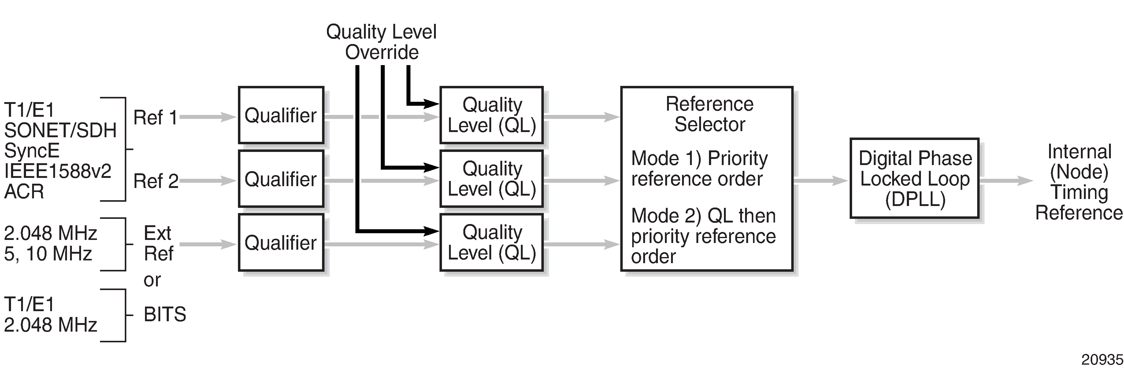
The G.803 and G.781 standards also define additional codes for internal use.
QL-INVx is generated internally by the system when an unallocated synchronization status message value is received; x represents the binary value of this synchronization status message. Within the 7705 SAR, all these independent values are assigned a single value of QL-INVALID.
QL-FAILED is generated internally by the system when the terminated network synchronization distribution trail is in the signal fail state.
QL-UNKNOWN is generated internally by the system to differentiate from a received QL-STU code. It is equivalent to QL-STU for the purposes of quality level selection.
If the node clock is in a holdover state, a holdover message is generated internally by the system and the transmitted SSM quality level value on an SSM-capable port is st3, eec1, eec2, or ssu-b, depending on the type of interface (as shown in Quality Level (QL) Values by Interface Type (SDH, SONET, SyncE) and Quality Level (QL) Values by Interface Type (E1 and T1)).
| SSM Quality Level Value Received on Port | Internal Relative Quality Level | SSM Quality Level Value to be Transmitted | ||
|---|---|---|---|---|
|
SDH interface SyncE interface in SDH mode |
SONET interface SyncE interface in SONET mode |
SDH interface SyncE interface in SDH mode |
SONET interface SyncE interface in SONET mode |
|
0010 (prc) |
0001 (prs) |
Best quality 1 |
0010 (prc) |
0001 (prs) |
— |
0000 (stu) |
|
0100 (ssu-a) |
0000 (stu) |
— |
0111 (st2) |
|
0100 (ssu-a) |
0111 (st2) |
0100 (ssu-a) |
0100 (tnc) |
|
0100 (ssu-a) |
0100 (tnc) |
— |
1101 (st3e) |
|
1000 (ssu-b) |
1101 (st3e) |
1000 (ssu-b) |
— |
|
1000 (ssu-b) |
1010 (st3/eec2) |
— |
1010 (st3/eec2) |
|
1011 (sec/eec1) |
1010 (st3/eec2) |
1011 (sec/eec1) |
— |
Lowest quality qualified in QL-enabled mode |
1011 (sec/eec1) |
1100 (smc) |
— |
1100 (smc) |
See note 2 |
1111 (dnu) |
1100 (smc) |
1111 (dnu) |
1111 (dus) |
See note 2 |
1111 (dnu) |
1111 (dus) |
Any other |
Any other |
QL-INVALID |
1111 (dnu) |
1111 (dus) |
— |
— |
QL-FAILED |
1111 (dnu) |
1111 (dus) |
— |
— |
QL-UNC |
1011 (sec/eec1) |
1010 (st3/eec2) |
Notes:
-
As the received QL on the port drops from prc/prs to sec/eec1 (row 1 to row 8), the quality level of the internal SSU drops from ‟Best quality” to ‟Lowest quality”.
-
These quality level indications are considered to be lower than the internal clock of the system. They are relayed to the line interfaces when ql-selection is disabled. When ql-selection is enabled, these inputs are never selected. If there is no valid reference available for the internal clock, then the clock enters holdover mode and the quality level is QL-UNC.
| SSM Quality Level Value Received on Port | Internal Relative Quality Level | SSM Quality Level Value to be Transmitted | ||
|---|---|---|---|---|
| E1 interface | T1 interface (ESF) | E1 interface | T1 interface (ESF) | |
0010 (prc) |
00000100 11111111 (prs) |
Best quality1 |
0010 (prc) |
00000100 11111111 (prs) |
— |
00001000 11111111 (stu) |
|
0100 (ssu-a) |
00001000 11111111 (stu) |
— |
00001100 11111111 (st2) |
|
0100 (ssu-a) |
00001100 11111111 (st2) |
0100 (ssu-a) |
01111000 11111111 (tnc) |
|
0100 (ssu-a) |
01111000 11111111 (tnc) |
— |
01111100 11111111 (st3e) |
|
1000 (ssu-b) |
01111100 11111111 (st3e) |
1000 (ssu-b) |
— |
|
1000 (ssu-b) |
00010000 11111111 (st3) |
— |
00010000 11111111 (st3) |
|
1011 (sec) |
00010000 11111111 (st3) |
1011 (sec) |
— |
Lowest quality qualified in QL-enabled mode |
1011 (sec) |
00100010 11111111 (smc) |
— |
00100010 11111111 (smc) |
See note 2 |
1111 (dnu) |
00100010 11111111 (smc) |
1111 (dnu) |
00110000 11111111 (dus) |
See note 2 |
1111 (dnu) |
00110000 11111111 (dus) |
Any other |
N/A |
QL-INVALID |
1111 (dnu) |
00110000 11111111 (dus) |
— |
— |
QL-FAILED |
1111 (dnu) |
00110000 11111111 (dus) |
— |
— |
QL-UNC |
1011 (sec) |
00010000 11111111 (st3) |
Notes:
As the received QL on the port drops from prc/prs to sec/eec1 (row 1 to row 8), the quality level of the internal SSU drops from ‟Best quality” to ‟Lowest quality”.
These quality level indications are considered to be lower than the internal clock of the system. They are relayed to the line interfaces when ql-selection is disabled. When ql-selection is enabled, these inputs are never selected. If there is no valid reference available for the internal clock, then the clock enters holdover mode and the quality level is QL-UNC.
Timing Reference Selection Based on Quality Level
For a SONET/SDH interface, a BITS DS1 or E1 physical port, a DS1 or E1 port interface that supports SSM, or a synchronous Ethernet interface that supports ESMC, a timing input provides a quality level value to indicate the source of timing of the far-end transmitter. These values provide input to the selection processes on the nodal timing subsystem. This selection process determines which input to use to generate the signal on the SSM egress ports and the reference to use to synchronize the nodal clock, as described below.
For the two reference inputs (ref1 and ref2) and for the BITS input ports, if the interface configuration supports the reception of a QL over SSM or ESMC, then the quality level value is associated with the timing derived from that input.
For the two reference inputs and for the BITS input ports, if the interface configuration is T1 with SF framing, then the quality level associated with the input is QL-UNKNOWN.
For the two reference inputs, if they are synchronous Ethernet ports and the ESMC is disabled, then the quality level value associated with that input is QL-UNKNOWN.
For the two reference inputs and for the BITS input ports, if the interface configuration supports the reception of a QL over SSM (and not ESMC), and no SSM value has been received, then the quality level value associated with the input is QL-STU.
For the two reference inputs and for the BITS input ports, if the interface configuration supports the reception of a QL over SSM or ESMC, but the quality level value received over the interface is not valid for the type of interface, then the quality level value associated with that input is QL-INVALID.
For the two reference inputs, if they are external synchronization, DS3, or E3 ports, then the quality level value associated with the input is QL-UNKNOWN.
For the two reference inputs, if they are synchronous Ethernet ports and the ESMC is enabled but no valid ESMC Information PDU has been received within the previous 5 s, then the quality level value associated with that input is QL-FAILED.
If the user has configured an override for the quality level associated with an input, the node displays both the received and override quality level value for the input. If no value has been received, then the associated value is displayed instead.
After the quality level values have been associated with the system timing inputs, the two reference inputs and the external input timing ports are processed by the system timing module to select a source for the SSU. This selection process is described below.
Before an input can be used as a potential timing source, it must be enabled using the ql-selection command. If ql-selection is disabled, then the priority order of the inputs for the Synchronous Equipment Timing Generator (SETG) is the priority order configured under the ref-order command.
If ql-selection is enabled, then the priority of the inputs is calculated using the associated quality level value of the input and the priority order configured under the ref-order command. The inputs are ordered by the internal relative quality level (shown in the middle row in Quality Level (QL) Values by Interface Type (SDH, SONET, SyncE) ) based on their associated quality level values. If two or more inputs have the same quality level value, then they are placed in order based on where they appear in the ref-order priority. The priority order for the SETG is based on both the reference inputs and the external synchronization input ports.
When a prioritized list of inputs is calculated, the SETG and the external synchronization output ports are configured to use the inputs in their respective orders.
When the SETG and external synchronization output ports priority lists are programmed, then the highest-qualified priority input is used. To be qualified, the signal is monitored to ensure that it has the expected format and that its frequency is within the pull-in range of the SETG.
SSM/ESMC QL Transmission
If a port is using the SETG output as its timing reference, the port transmits the SSM corresponding to the QL of the SETG.
On the port that is selected as the reference for the SETG, the port transmits the DNU/DUS value in the SSM/ESMC.
If a BITS port is selected as the reference for the SETG, both BITS ports transmit DNU/DUS value.
An Ethernet port with a copper SFP always transmits DNU/DUS when SSM is enabled on the port. When SSM is enabled on a copper-based RJ45 Ethernet port, DNU/DUS is transmitted if the port phy-tx-clock is not configured as master. When SSM is enabled on a copper-based RJ45 Ethernet port and the port phy-tx-clock is configured as master, the port transmits the SSM value corresponding to the determined by the SSU.
DS1 Physical Port QL Transmission
DS1 signals can carry the quality level value of the timing source via the SSM transported within the 1544 kb/s signal Extended Super Frame (ESF) Data Link (DL), as specified in Recommendation G.704.
The format of the ESF data link messages is 0xxx xxx0 1111 1111, with the rightmost bit transmitted first. The 6 bits denoted by xxx xxx contain the message; some of these messages are reserved for synchronization messaging. It takes 32 frames (4 ms) to transmit all 16 bits of a complete DL message.
SSM over DS1 ESF is supported on the 7705 SAR-18 via the BITS ports and also on T1 ports on the 16-port T1/E1 ASAP Adapter card, the 32-port T1/E1 ASAP Adapter card, and the 7705 SAR-A, 7705 SAR-M, 7705 SAR-H, and 7705 SAR-X chassis.
E1 Physical Port QL Transmission
E1 signals can carry the quality level value of the timing source via one of the Sa bits (Sa4 to Sa8) in a synchronization status message, as described in G.704, section 2.3.4. Choosing which Sa bit carries the SSM is user-configurable.
SSM over E1 is supported on the 7705 SAR-18 via the BITS ports. SSM via an E1 port is supported on the 16-port T1/E1 ASAP Adapter card, the 32-port T1/E1 ASAP Adapter card, and the 7705 SAR-A, 7705 SAR-M, and 7705 SAR-X chassis.
System Configuration Process Overview
System Configuration and Implementation Flow displays the process to provision basic system parameters.
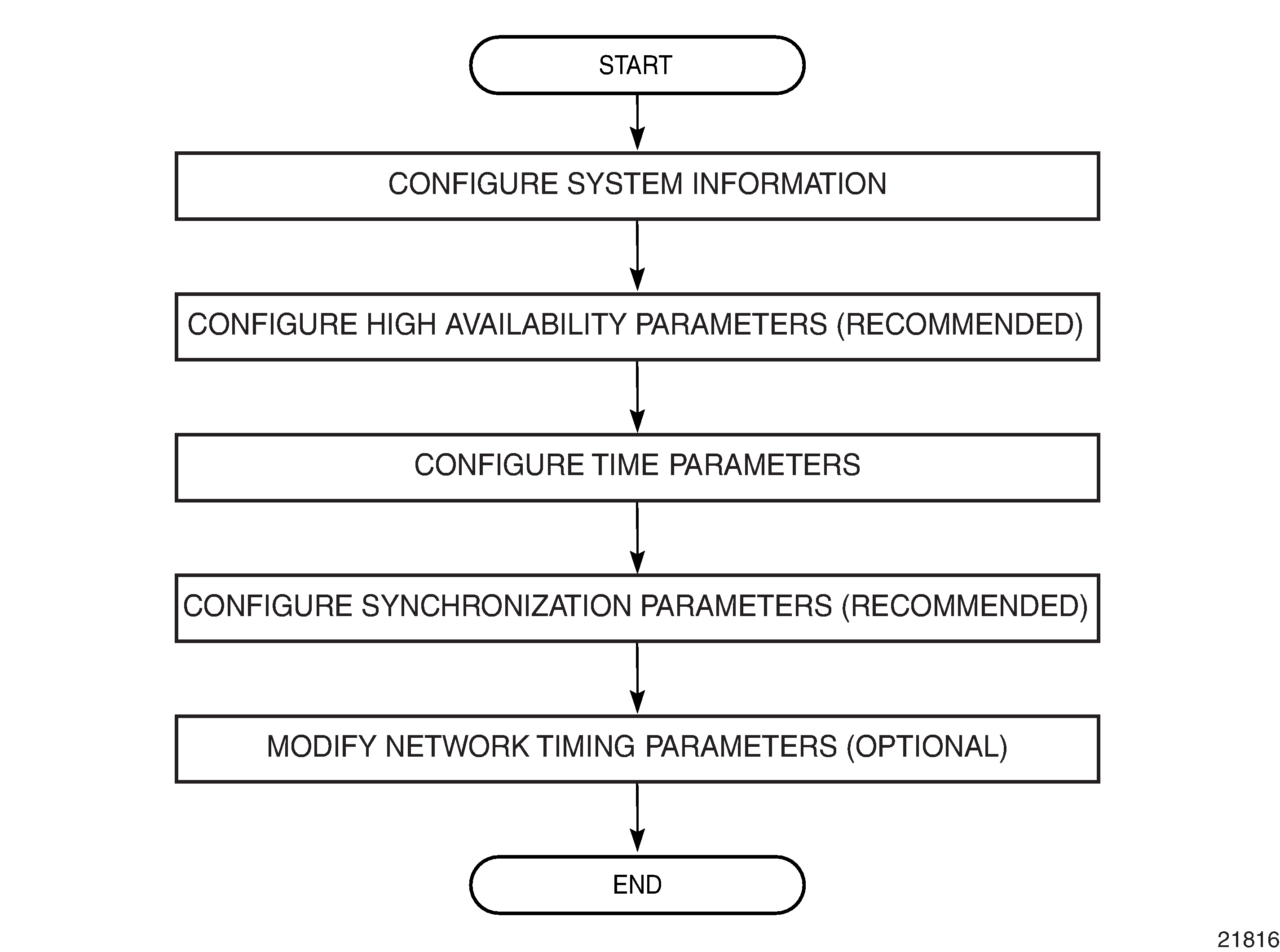
Configuration Notes
This section describes system configuration guidelines and restrictions.
The 7705 SAR must be properly initialized and the boot loader and BOF files successfully executed to access the CLI.
Configuring System Management with CLI
This section provides information about configuring system management features with CLI.
Topics in this section include:
System Management Configuration
Saving Configurations
Whenever configuration changes are made, the modified configuration must be saved so that the changes are not lost when the system is rebooted. The system uses the configuration and image files, as well as other operational parameters necessary for system initialization, according to the locations specified in the boot options file (BOF). For more information about the BOF, see Boot Options.
Configuration files are saved by executing explicit or implicit command syntax.
An explicit save writes the configuration to the location specified in the save command syntax (the file-url option).
An implicit save writes the configuration to the file specified in the primary configuration location.
If the file-url option is not specified in the save command syntax, the system attempts to save the current configuration to the current BOF primary configuration source. If the primary configuration source (path and/or filename) changed since the last boot, the new configuration source is used.
The save command includes an option to save both default and non-default configuration parameters (the detail option).
The index option specifies that the system preserves system indexes when a save command is executed, regardless of the persistent status in the BOF file. During a subsequent boot, the index file is read along with the configuration file. As a result, a number of system indexes are preserved between reboots, including the interface index, LSP IDs, and path IDs. This reduces resynchronizations of the Network Management System (NMS) with the affected network element.
If the save attempt fails at the destination, an error occurs and is logged. The system does not try to save the file to the secondary or tertiary configuration sources unless the path and filename are explicitly named with the save command.
Basic System Configuration
This section provides information to configure system parameters and provides configuration examples of common configuration tasks. The minimal system parameters that should be configured are:
The following example displays a basic system configuration:
ALU-1>config>system# info
#------------------------------------------
echo "System Configuration"
#------------------------------------------
        name "ALU-1"
        coordinates "Unknown"
        snmp
        exit
        security
            snmp
                community "private" rwa version both
            exit
        exit
        time
            ntp
                server 192.168.15.221
                no shutdown
            exit
            sntp
                shutdown
            exit
            zone GMT
        exit
----------------------------------------------
ALU-1>config>system#
Common Configuration Tasks
This section provides a brief overview of the tasks that must be performed to configure system parameters and provides the CLI commands.
System Information
This section covers the basic system information parameters to configure the physical location of the 7705 SAR, contact information, router location information such as an address, floor, and room number, global navigation satellite system (GNSS) coordinates, and system name.
Use the CLI syntax displayed below to configure the following system components:
System Information Parameters
General system parameters include:
Name
Use the system name command to configure a name for the device. The name is used in the prompt string. Only one system name can be configured. If multiple system names are configured, the last one encountered overwrites the previous entry.
Use the following CLI syntax to configure the system name:
- CLI Syntax:
config>systemnamesystem-name
- Example:
config>system# name ALU-1
The following example displays the system name:
ALU-1>config>system# info
#------------------------------------------
echo "System Configuration"
#------------------------------------------
        name "ALU-1"
. . .
        exit
----------------------------------------------
ALU-1>config>system#
Contact
Use the contact command to specify the name of a system administrator, IT staff member, or other administrative entity.
- CLI Syntax:
config>systemcontactcontact-name
- Example:
config>system# contact ‟Fred Information Technology”
Location
Use the location command to specify the system location of the device. For example, enter the city, building address, floor, and room number where the router is located.
Use the following CLI syntax to configure the location:
- CLI Syntax:
config>systemlocationlocation
- Example:
config>system# location ‟Bldg.1-floor 2-Room 201”
CLLI Code
The Common Language Location Code (CLLI code) is an 11-character standardized geographic identifier that is used to uniquely identify the geographic location of a 7705 SAR.
Use the following CLI command syntax to define the CLLI code:
- CLI Syntax:
config>systemclli-codeclli-code
- Example:
config>system# clli-code abcdefg1234
Coordinates
Use the optional coordinates command to specify the GNSS location of the device. If the string contains spaces, the entire string must be enclosed within double quotes.
Use the following CLI syntax to configure the location:
- CLI Syntax:
config>systemcoordinatescoordinates
- Example:
config>system# coordinates "N 45 58 23, W 34 56 12"
The following example displays the configuration output of the general system commands:
ALU-1>config>system# info
#------------------------------------------
echo "System Configuration"
#------------------------------------------
name "ALU-1"
        contact "Fred Information Technology"
        location "Bldg.1-floor 2-Room 201"
        clli-code "abcdefg1234"
        coordinates "N 45 58 23, W 34 56 12"

. . .
        exit
----------------------------------------------
ALU-1>config>system#
System Identifier
The system identifier is an IPv4 address that can be used to uniquely identify the 7705 SAR in the network in situations where the system IP address may change dynamically.
Use the following CLI command syntax to define the system identifier:
- CLI Syntax:
config>systemidentifierid
- Example:
config>system# identifier 192.0.2.255
System Time Elements
The system clock maintains time according to Coordinated Universal Time (UTC). Configure information time zone and summer time (daylight savings time) parameters to correctly display time according to the local time zone.
Time elements include:
Use the following CLI syntax to configure system time elements. The authentication-key des keyword is not supported if the 7705 SAR node is running in FIPS-140-2 mode.
- CLI Syntax:
config>systemtimedst-zone zone-nameend {end-week} {end-day} {end-month} [hours-minutes]offset offsetstart {start-week} {start-day} {start-month} [hours-minutes]gnssport port-id time-ref-priority priority-valuentpauthentication-checkauthentication-key key-id {key key} [hash | hash2] {type des | message-digest}broadcastclient [router router-name] {interface ip-int-name} [authenticate]mda-timestampmulticastclient [authenticate]server {ip-address | ipv6-address} [key-id key-id] [version version] [prefer]no shutdownptpclock clock-id time-ref-priority priority-valueclock csm time-ref-priority priority-valuesntpbroadcast-clientserver-address ip-address [version version-number] [normal | preferred] [interval seconds]no shutdowntod1-ppsmessage-type {ct | cm | irig-b002-b122 | irig-b003-b123 | irig-b006-b126 | irig-b007-b127}zone {std-zone-name | non-std-zone-name} [hh[:mm]]
Zone
The zone command sets the time zone and/or time zone offset for the router. The 7705 SAR supports system-defined and user-defined time zones. The system-defined time zones are listed in System-defined Time Zones .
- CLI Syntax:
config>system>timezone {std-zone-name | non-std-zone-name}[hh [:mm]]
- Example:
config>system>time#zone GMT
The following example displays the zone output:
ALU-1>config>system>time# info
----------------------------------------------
         ntp
                server 192.168.15.221
                no shutdown
         exit
         sntp
                shutdown
         exit
         zone UTC
----------------------------------------------
ALU-1>config>system>time#
| Acronym | Time Zone Name | UTC Offset |
|---|---|---|
| Europe: | ||
GMT |
Greenwich Mean Time |
UTC |
WET |
Western Europe Time |
UTC |
WEST |
Western Europe Summer Time |
UTC +1 hour |
CET |
Central Europe Time |
UTC +1 hour |
CEST |
Central Europe Summer Time |
UTC +2 hours |
EET |
Eastern Europe Time |
UTC +2 hours |
EEST |
Eastern Europe Summer Time |
UTC +3 hours |
MSK |
Moscow Time |
UTC +3 hours |
MSD |
Moscow Summer Time |
UTC +4 hours |
US and Canada: |
||
AST |
Atlantic Standard Time |
UTC -4 hours |
ADT |
Atlantic Daylight Time |
UTC -3 hours |
EST |
Eastern Standard Time |
UTC -5 hours |
EDT |
Eastern Daylight Saving Time |
UTC -4 hours |
CST |
Central Standard Time |
UTC -6 hours |
CDT |
Central Daylight Saving Time |
UTC -5 hours |
MST |
Mountain Standard Time |
UTC -7 hours |
MDT |
Mountain Daylight Saving Time |
UTC -6 hours |
PST |
Pacific Standard Time |
UTC -8 hours |
PDT |
Pacific Daylight Saving Time |
UTC -7 hours |
HST |
Hawaiian Standard Time |
UTC -10 hours |
AKST |
Alaska Standard Time |
UTC -9 hours |
AKDT |
Alaska Standard Daylight Saving Time |
UTC -8 hours |
Australia and New Zealand: |
||
AWST |
Western Standard Time |
UTC +8 hours |
ACST |
Central Standard Time |
UTC +9.5 hours |
AEST |
Eastern Standard/Summer Time |
UTC +10 hours |
NZT |
New Zealand Standard Time |
UTC +12 hours |
NZDT |
New Zealand Daylight Saving Time |
UTC +13 hours |
Summer Time Conditions
The dst-zone command configures the start and end dates and offset for summer time or daylight savings time to override system defaults or for user-defined time zones.
When configured, the time is adjusted by adding the configured offset when summer time starts and subtracting the configured offset when summer time ends.
- CLI Syntax:
config>system>timedst-zone zone-nameend {end-week} {end-day} {end-month} [hours-minutes]offset offsetstart {start-week} {start-day} {start-month} [hours-minutes]
- Example:
config>system>time# dst-zone ptconfig>system>time>dst-zone# start second sunday april 02:00end first sunday october 02:00config>system>time>dst-zone# offset 0
If the time zone configured is listed in System-defined Time Zones , then the starting and ending parameters and offset do not need to be configured with this command unless there is a need to override the system defaults. The command returns an error if the start and ending dates and times are not available either in System-defined Time Zones or entered as optional parameters in this command.
The following example displays the configured parameters.
A:ALU-1>config>system>time>dst-zone# info
----------------------------------------------
                start second sunday april 02:00
                end first sunday october 02:00
                offset 0
----------------------------------------------
A:ALU-1>config>system>time>dst-zone# offset 0
NTP
Network Time Protocol (NTP) is defined in RFC 1305, Network Time Protocol (Version 3) Specification, Implementation and Analysis. It allows for participating network nodes to keep time more accurately and maintain time in a synchronized manner between all participating network nodes.
NTP time elements include:
- CLI Syntax:
config>system>timentpauthentication-checkauthentication-key key-id {key key} [hash | hash2] {type des | message-digest}broadcastclient [router router-name] {interface ip-int-name} [authenticate]mda-timestampmulticastclient [authenticate]server {ip-address | ipv6-address} [key-id key-id] [version version] [prefer]no shutdown
Authentication-check
The authentication-check command provides for the option to skip the rejection of NTP PDUs that do not match the authentication key or authentication type requirements. The default behavior when authentication is configured is to reject all NTP protocol PDUs that have a mismatch in either the authentication key ID, type, or key.
When authentication-check is configured, NTP PDUs are authenticated on receipt. However, mismatches cause a counter to be increased, one counter for key ID, one for type, and one for key value mismatches.
- CLI Syntax:
config>system>time>ntpauthentication-check
- Example:
config>system>time>ntp#authentication-checkconfig>system>time>ntp# no shutdown
Authentication-key
This command configures an authentication key ID, key type, and key used to authenticate NTP PDUs sent to and received from other network elements participating in the NTP protocol. For authentication to work, the authentication key ID, authentication type, and authentication key value must match.
- CLI Syntax:
config>system>time>ntpauthentication-key key-id {key key} [hash | hash2] type {des | message-digest}
- Example:
config>system>time>ntp#authentication-key 1 key A type desconfig>system>time>ntp# no shutdown
The following example shows NTP disabled with the authentication-key parameter enabled.
A:ALU-1>config>system>time>ntp# info
----------------------------------------------
                shutdown
                authentication-key 1 key "OAwgNUlbzgI" hash2 type des
----------------------------------------------
A:ALU-1>config>system>time>ntp#
Broadcastclient
The broadcastclient command enables listening to NTP broadcast messages on the specified interface.
- CLI Syntax:
config>system>time>ntpbroadcastclient[router router-name] {interface ip-int-name} [authenticate]
- Example:
config>system>time>ntp#broadcastclientinterface int11config>system>time>ntp#no shutdown
The following example shows NTP enabled with the broadcastclient parameter enabled.
ALU-1>config>system>time# info
----------------------------------------------
            ntp
                broadcastclient interface int11
                no shutdown
            exit
            dst-zone PT
                start second sunday april 02:00
                end first sunday october 02:00
                offset 0
            exit
            zone UTC
----------------------------------------------
ALU-1>config>system>time#
MDA-timestamp
The mda-timestamp command enables timestamping on an adapter card by the network processor to allow more accurate timestamping for in-band NTP packets. Timestamping on an adapter card is only performed on Ethernet-based adapter cards. This command can only be set if NTP is shut down and all the NTP servers are not associated with an authentication key. This command does not change the behavior of NTP over the management port. Use the no form of this command to revert to the default behavior of having NTP packets timestamped by the CSM.
- CLI Syntax:
config>system>time>ntpmda-timestamp
- Example:
config>system>time>ntp#mda-timestampconfig>system>time>ntp#no shutdown
The following example shows enhanced NTP performance enabled using the mda-timestamp command.
A:ALU-1>config>system>time>ntp# info
----------------------------------------------
                shutdown
                no authentication-key 1
                mda-timestamp
----------------------------------------------
A:ALU-1>config>system>time>ntp#
Multicastclient
This command is used to configure an address to receive multicast NTP messages on the CSM Management port. The no form of this command removes the multicast client.
If multicastclient is not configured, all NTP multicast traffic is ignored.
- CLI Syntax:
config>system>time>ntpmulticastclient [authenticate]
- Example:
config>system>time>ntp#multicastclient authenticateconfig>system>time>ntp#no shutdown
The following example shows NTP enabled with the multicastclient command configured.
ALU-1>config>system>time# info
----------------------------------------------
              server 192.168.15.221
              multicastclient
              no shutdown
----------------------------------------------
ALU-1>config>system>time##
Server
The server command is used when the node should operate in client mode with the NTP server specified in the address field. Use the no form of this command to remove the server with the specified address from the configuration.
Up to five NTP servers can be configured.
- CLI Syntax:
config>system>time>ntpserver {ip-address | ipv6-address} [key-id key-id] [version version] [prefer]
- Example:
config>system>time>ntp#server 192.168.1.1 key-id 1config>system>time>ntp# no shutdown
The following example shows NTP enabled with the server command configured.
A:sim1>config>system>time>ntp# info
----------------------------------------------
            no shutdown
            server 192.168.1.1 key 1
----------------------------------------------
A:sim1>config>system>time>ntp#
SNTP
SNTP is a compact, client-only version of the NTP. SNTP can only receive the time from SNTP/NTP servers; it cannot be used to provide time services to other systems. SNTP can be configured in either broadcast or unicast client mode.
SNTP time elements include:
- CLI Syntax:
config>system>timesntpbroadcast-clientserver-address ip-address [version version-number] [normal | preferred] [interval seconds]no shutdown
Broadcast-client
The broadcast-client command enables listening at the global device level to SNTP broadcast messages on interfaces with broadcast client enabled.
- CLI Syntax:
config>system>time>sntpbroadcast-client
- Example:
config>system>time>sntp#broadcast-clientconfig>system>time>sntp#no shutdown
The following example shows SNTP enabled with the broadcast-client parameter enabled.
ALU-1>config>system>time# info
----------------------------------------------
            sntp
                broadcast-client
                no shutdown
            exit
            dst-zone PT
                start second sunday april 02:00
                end first sunday october 02:00
                offset 0
            exit
            zone GMT
----------------------------------------------
ALU-1>config>system>time#
Server-address
The server-address command configures an SNTP server for SNTP unicast client mode.
- CLI Syntax:
config>system>time>sntpserver-address ip-address version version-number] [normal | preferred] [interval seconds]
- Example:
config>system>time>sntp# server-address10.10.0.94version1preferredinterval100
The following example shows SNTP enabled with the server-address parameter configured.
ALU-1>config>system>time# info
----------------------------------------------
            sntp
                server-address 10.10.0.94 version 1 preferred interval 100
                no shutdown
            exit
            dst-zone PT start-date 2018/04/04 12:00 end-date 2018/10/25 12:00
            zone GMT
----------------------------------------------
ALU-1>config>system>time#
PTP
Precision Time Protocol (PTP) is a timing-over-packet protocol defined in the IEEE 1588v2 standard 1588 2008. PTP provides the capability to synchronize network elements to a Stratum-1 clock or primary reference clock (PRC) traceable source over a network that may or may not be PTP-aware.
The ptp command specifies the PTP source as an option for recovered time. The specific PTP clock is identified by clock-id (from 1 to 16 for PTP clocks that use IPv4 or IPv6 encapsulation, and csm for PTP clocks that use Ethernet encapsulation) and has an assigned priority-value (from 1 to 16).
- CLI Syntax:
config>system>timeptpclock clock-id time-ref-priority priority-valueclock csm time-ref-priority priority-value
- Example:
config>system>time# ptpconfig>system>time>ptp# clock 1 time-ref-priority 1
Time-of-Day Measurement (ToD-1pps)
The 7705 SAR can receive and extract time of day/phase recovery from a 1588 grandmaster clock or boundary clock and transmit the recovered time of day/phase signal to an external device such as a base station through an external time of day port, where available. Transmission is through the ToD or ToD/PPS Out port with a 1 pulse/s output signal. The port interface communicates the exact time of day by the rising edge of the 1 pulse/s signal.
The tod-1pps command specifies the format for the time of day (ToD) message that is transmitted out the ToD or ToD/PPS Out port and specifies whether the 1pps output is enabled.
- CLI Syntax:
config>system>timetod-1ppsmessage-type {ct | cm | irig-b002-b122 | irig-b003-b123 | irig-b006-b126 | irig-b007-b127}output
- Example:
config>system>time# tod-1ppsconfig>system>time>tod-1pps# message-type ctconfig>system>time>tod-1pps# output
GNSS
For a 7705 SAR chassis that is equipped with a GNSS receiver and an attached GNSS antenna, the GNSS receiver can be used as a synchronous timing source. GNSS data is used to provide network-independent frequency and ToD synchronization.
The gnss command specifies a GNSS receiver port as a synchronous timing source. The specific GNSS receiver port is identified by port-id and has an assigned priority-value (from 1 to 16).
- CLI Syntax:
config>system>timegnssport port-id time-ref-priority priority-value
- Example:
config>system>time# gnssconfig>system>time>gnss# port 1/2/1 time-ref-priority 1
CRON
The cron command is used for periodic and date- and time-based scheduling.
The schedule function configures the type of schedule to run, including one-time-only (one-shot), periodic, or calendar-based runs. All runs are scheduled by month, day, hour, minute, and interval (seconds). If end-time and interval are both configured, whichever condition is reached first is applied.
- CLI Syntax:
-
config>system>cronschedule schedule-name [owner schedule-owner]count numberday-of-month {day-number [..day-number] | all}description description-stringend-time [date | day-name] timehour {hour-number [..hour-number] | all}interval secondsminute {minute-number [..minute-number] | all}month {month-number [..month-number] | month-name [..month-name] | all}script-policy policy-name [owner policy-owner]type schedule-typeweekday {weekday-number [..weekday-number] | day-name [..day-name] | all}no shutdown
The following example creates a schedule named ‟test2” to run a script policy named ‟test_policy” every 15 minutes on the 17th of each month and every Friday until noon on December 17, 2018:
- Example:
-
config>system>cron# schedule test2config>system>cron>sched# day-of-month 17config>system>cron>sched# end-time 2018/12/17 12:00config>system>cron>sched# minute 0 15 30 45config>system>cron>sched# weekday fridayconfig>system>cron>sched# script-policy ‟test_policy”config>system>cron>sched# no shutdown
Configuring Script Parameters
The 7705 SAR provides centralized script management for CLI scripts that are used by CRON and the Event Handling System (EHS). Scripts contain a set of CLI commands that are executed at a scheduled time or when an event is triggered.
The script and script-policy commands within the config>system>script-control context configure the script parameters.
The script command assigns a name to the script and references its location. When the script has been defined, a script-policy is configured that calls the previously configured script. The script-policy also specifies a location and filename that stores the results of the script run.
- CLI Syntax:
config>systemscript-controlscript script-name [owner script-owner]description description-stringlocation file-urlno shutdownscript-policy policy-name [owner policy-owner]expire-time {seconds | forever}lifetime {seconds | forever}max-completed unsignedresults file-urlscript script-name [owner script-owner]no shutdown
- Example:
config>system# script-controlconfig>system>script-control# script ‟test_script”config>system>script-control>script# location "cf3:/test.txt"config>system>script-control>script# no shutdownconfig>system>script-control>script# exitconfig>system>script-control# script-policy ‟test_policy”config>system>script-control>script-policy# results "cf3:/script-results.txt"config>system>script-control>script-policy# max-completed 4config>system>script-control>script-policy# expire-time 7200config>system>script-control>script-policy# no shutdownconfig>system>script-control>script-policy# exitconfig>system>script-control># exit
The following displays the configuration:
Dut-B>config>system>script-control# info
----------------------------------------------
            script "test_script"
                location "cf3:/test.txt"
                no shutdown
            exit
            script-policy "test_policy"
                results "cf3:/script-results.txt"
                script "test_script"
                max-completed 4
                expire-time 7200
                no shutdown
            exit
----------------------------------------------
Dut-B>config>system>script-control#
Configuring Synchronization and Redundancy
Use the CLI syntax displayed below to configure various synchronization and redundancy parameters:
Configuring Synchronization
The switchover-exec command specifies the location and name of the CLI script file executed following a redundancy switchover from the previously active CSM card.
- CLI Syntax:
config>systemswitchover-exec file-url
Configuring Manual Synchronization
Automatic synchronization can be configured in the config>system> synchronization context.
Manual synchronization can be configured with the following command:
- CLI Syntax:
adminredundancysynchronize {boot-env | config}
- Example:
admin>redundancy# synchronize config
The following shows the output that displays during a manual synchronization:
ALU-1>admin>redundancy# synchronize config

Syncing configuration......

Syncing configuration.....Completed.
ALU-1#
Forcing a Switchover
The force-switchover now command forces an immediate switchover to the standby CSM card.
- CLI Syntax:
adminredundancyforce-switchover [now]
- Example:
admin>redundancy# force-switchover now
ALU-1# admin redundancy force-switchover now
ALU-1y#
Resetting...
?
If the active and standby CSMs are not synchronized for some reason, users can manually synchronize the standby CSM by rebooting the standby by issuing the admin reboot standby command on the active or the standby CSM.
Configuring Synchronization Options
Network operators can specify the type of synchronization operation to perform between the primary and secondary CSMs after a change has been made to the configuration files or the boot environment information contained in the BOF.
Use the following CLI command to configure the boot-env option:
- CLI Syntax:
configredundancysynchronize {boot-env | config}
- Example:
config>redundancy# synchronize boot-env
The following displays the configuration:
*ALU-1>config>redundancy# synchronize boot-env
*ALU-1>config>redundancy# show redundancy synchronization
===============================================================================
Synchronization Information
===============================================================================
Standby Status               : disabled
Last Standby Failure         : N/A
Standby Up Time              : N/A
Failover Time                : N/A
Failover Reason              : N/A
Boot/Config Sync Mode        : Boot Environment
Boot/Config Sync Status      : No synchronization
Last Config File Sync Time   : Never
Last Boot Env Sync Time      : Never
===============================================================================
Use the following CLI command to configure the config option:
- CLI Syntax:
configredundancysynchronize {boot-env | config}
- Example:
config>redundancy# synchronize config
The following example displays the configuration.
ALU-1>config>redundancy# synchronize config
ALU-1>config>redundancy# show redundancy synchronization
===================================================
Synchronization Information
===================================================
Synchronize Mode        : Configuration
Synchronize Status      : No synchronization
Last Config Sync Time   : 2006/06/27 09:17:15
Last Boot Env Sync Time : 2006/06/24 07:16:37
===================================================
Configuring Multi-Chassis Redundancy
When configuring multi-chassis redundancy, configuration must be performed on the two nodes that forms redundant-pair peer nodes. Each node points to its peer using the peer command.
When creating a multi-chassis LAG, the LAG must first be created under the config>lag lag-id context. Additionally, the LAG must be in access mode and LACP must be enabled (active or passive). Under the multi-chassis>peer>mc-lag context, the lag-id is the ID of the previously created LAG.
Use the following CLI syntax to configure multi-chassis redundancy features:
- CLI Syntax:
config>redundancymulti-chassispeer ip-addressauthentication-key[authentication-key | hash-key] [hash | hash2]description description-stringmc-laghold-on-neighbor-failure multiplierkeep-alive-interval intervallag lag-id lacp-key admin-key system-id system-id [remote-lag lag-id] system-priority system-priorityno shutdownsource-address ip-address
- Example:
config>redundancy#config>redundancy# multi-chassisconfig>redundancy>multi-chassis# peer 10.10.10.2 createconfig>redundancy>multi-chassis>peer# description ‟Mc-Lag peer 10.10.10.2”config>redundancy>multi-chassis>peer# mc-lagconfig>redundancy>mc>peer>mc-lag# lag 1 lacp-key 32666 system-id 00:00:00:33:33:33 system-priority 32888config>redundancy>mc>peer>mc-lag# no shutdownconfig>redundancy>mc>peer>mc-lag# exitconfig>redundancy>multi-chassis>peer# no shutdownconfig>redundancy>multi-chassis>peer# exitconfig>redundancy>multi-chassis# exitconfig>redundancy#
The following displays the configuration:
A:7705:Dut-A>config>redundancy# info
----------------------------------------------
            multi-chassis
                peer 10.10.10.2 create
                   description "Mc-Lag peer 10.10.10.2"
                    mc-lag
                       lag 1 lacp-key 32666 system-id 00:00:00:33:33:33 system
priority 32888
                       no shutdown
                    exit
                    no shutdown
                exit
            exit
----------------------------------------------
A:7705:Dut-A>config>redundancy#
Configuring ATM Parameters
The ATM context configures system-wide ATM parameters.
- CLI Syntax:
config>systematmatm-location-id location-id
- Example:
config>system# atmconfig>system>atm# atm-location-id 03:00:00:00:00:00:00:00:00:00:00:00:00:00:00:00
The following example shows the ATM configuration.
ALU-1>config>system>atm# info
----------------------------------------------
            atm-location-id 03:00:00:00:00:00:00:00:00:00:00:00:00:00:00:00
exit
----------------------------------------------
ALU-1>config>system>atm#
Configuring Backup Copies
The config-backup command allows you to specify the maximum number of backup versions of configuration and index files kept in the primary location.
For example, if the config-backup count is set to 5 and the configuration file is called xyz.cfg, the file xyz.cfg is saved with a .1 extension when the save command is executed. Each subsequent config-backup command increments the numeric extension until the maximum count is reached. The oldest file (5) is deleted as more recent files are saved.
xyz.cfg
xyz.cfg.1
xyz.cfg.2
xyz.cfg.3
xyz.cfg.4
xyz.cfg.5
xyz.ndx
Each persistent index file is updated at the same time as the associated configuration file. When the index file is updated, then the save is performed to xyz.cfg and the index file is created as xyz.ndx. Synchronization between the active and standby CSMs is performed for all configurations and their associated persistent index files.
- CLI Syntax:
config>systemconfig-backup count
- Example:
config>system#config>system# config-backup 7
The following example shows the config-backup configuration.
ALU-1>config>system> info
#------------------------------------------
echo "System Configuration"
#------------------------------------------
        name "ALU-1"
        contact "Fred Information Technology"
        location "Bldg.1-floor 2-Room 201"
        clli-code "abcdefg1234"
        coordinates "N 45 58 23, W 34 56 12"
        config-backup 7
...
----------------------------------------------
ALU-1>config>system>
Configuring System Administration Parameters
Use the CLI syntax displayed below to configure various system administration parameters.
Administrative parameters include:
- CLI Syntax:
admincertificateclearcomparedebug-savedisconnect [address ip-address |usernameuser-name | session-id session-id |{console | telnet | ftp | ssh | mct}]display-config [detail | index]enable-techreboot [active | standby][upgrade][now]redundancyrollbacksave [file-url] [detail] [index]set-time date timesystemtech-supportupdate
Disconnect
The disconnect command immediately disconnects a user from a console, Telnet, FTP, SSH, SFTP, or MPT craft terminal (MCT) session.
The ssh keyword disconnects users connected to the node via SSH or SFTP.
- CLI Syntax:
admindisconnect [address ip-address | username user-name | session-id session-id | {console | telnet | ftp | ssh | mct}]
- Example:
admin# disconnect
The following example displays the disconnect command results.
     ALU-1>admin# disconnect
     ALU-1>admin# Logged out by the administrator
     Connection to host lost.
Set-time
Use the set-time command to set the system date and time. The time entered should be accurate for the time zone configured for the system. The system converts the local time to UTC before saving to the system clock which is always set to UTC. If SNTP or NTP is enabled (no shutdown), this command cannot be used. The set-time command does not take into account any daylight saving offset if defined.
- CLI Syntax:
adminset-time date time
- Example:
admin# set-time 2010/09/24 14:10:00
The following example displays the set-time command results.
     ALU-1# admin set-time 2010/09/24 14:10:00
     ALU-1# show time
     Fri Sept 24 14:10:25 UTC 2010
     ALU-1#
Display-config
The display-config command displays the system’s running configuration.
- CLI Syntax:
admindisplay-config [detail] [index]
- Example:
admin# display-config detail
The following example displays a portion of the display-config detail command results.
ALU-1>admin# display-config detail
# TiMOS-B-0.0.current both/i386 NOKIA SAR 7705
# Copyright (c) 2016 Nokia.
# All rights reserved. All use subject to applicable license agreements.
# Built on Fri Sept 24 01:32:43 EDT 2016 by csabuild in /rel0.0/I270/panos/main

# Generated FRI SEPT 24 14:48:31 2016 UTC

exit all
configure
#------------------------------------------
echo "System Configuration"
#------------------------------------------
    system
        name "ALU-1"
        contact "Fred Information Technology"
        location "Bldg.1-floor 2-Room 201"
        clli-code "abcdefg1234"
        coordinates "N 45 58 23, W 34 56 12"
        config-backup 7
        boot-good-exec "ftp://*:*@xxx.xxx.xxx.xx/home/csahwreg17/images/env.cfg”
        no boot-bad-exec
        no switchover-exec
        snmp
            engineID "0000197f00006883ff000000"
            packet-size 1500
            general-port 161
            no shutdown
        exit
        login-control
            ftp
                inbound-max-sessions 3
            exit
            ssh
                no disable-graceful-shutdown
                inbound-max-sessions 5
                outbound-max-sessions 5
                ttl-security 100
            exit
            telnet
                no enable-graceful-shutdown
                inbound-max-sessions 5
                outbound-max-sessions 5
                ttl-security 50
            exit
            idle-timeout 1440
            pre-login-message "Property of Service Routing Inc.Unauthorized access
prohibited."
            motd text ‟Notice to all users: Software upgrade scheduled 3/2 1:00 AM"
            login-banner
            no exponential-backoff
        exit
        atm
            no atm-location-id
        exit
        security
            management-access-filter
                default-action permit
                entry 1
                    no description
...
ALU-1>admin#
Tech-support
The tech-support command creates a system core dump.
Save
The save command saves the running configuration to a configuration file. When the debug-save parameter is specified, debug configurations are saved in the config file. If this parameter is not specified, debug configurations are not saved between reboots.
- CLI Syntax:
adminsave [file-url] [detail] [index]debug-save[file-url]
- Example:
admin# save ftp://test:test@192.168.x.xx/./1.cfgadmin# debug-save debugsave.txt
The following example displays the save command results.
ALU-1>admin# save ftp://test:test@192.168.x.xx/./1x.cfg
Writing file to ftp://test:test@192.168.x.xx/./1x.cfg
Saving configuration ...Completed.
ALU-1>admin# debug-save ftp://test:test@192.168.x.xx/./debugsave.txt
Writing file to ftp://julie:julie@192.168.x.xx/./debugsave.txt
Saving debug configuration .....Completed.
Reboot
The reboot command reboots the router, including redundant CSMs in redundant systems. If the now option is not specified, you are prompted to confirm the reboot operation. The reboot upgrade command forces an upgrade of the boot ROM and a reboot.
- CLI Syntax:
adminreboot [active | standby] | [upgrade] [now]
- Example:
admin# reboot now
If synchronization fails, the standby does not reboot automatically. The show redundancy synchronization command displays synchronization output information.
Post-Boot Configuration Extension Files
Two post-boot configuration extension files are supported and are triggered when either a successful or failed boot configuration file is processed. The commands specify URLs for the CLI scripts to be run following the completion of the boot-up configuration. A URL must be specified or no action is taken. The commands are persistent between router (re)boots and are included in the configuration saves (admin>save).
- CLI Syntax:
config>systemboot-bad-exec file-urlboot-good-exec file-url
- Example:
config>system# boot-bad-exec ftp://t:t@192.168.xx.xxx/./fail.cfgconfig>system# boot-good-execftp://test:test@192.168.xx.xxx/./ok.cfg
The following example displays the command output:
ALU-1>config>system# info
#------------------------------------------
echo "System Configuration"
#------------------------------------------
        name "ALU-1"
        contact "Fred Information Technology"
        location "Bldg.1-floor 2-Room 201"
        clli-code "abcdefg1234"
        coordinates "N 45 58 23, W 34 56 12"
        config-backup 7
        boot-good-exec "ftp://test:test@192.168.xx.xxx/./ok.cfg"
        boot-bad-exec "ftp://test:test@192.168.xx.xxx/./fail.cfg"
        sync-if-timing
            begin
            ref-order ref1 ref2 bits
..
----------------------------------------------
ALU-1>config>system#
Show Command Output and Console Messages
The show>system>information command displays the current value of the bad/good exec URLs and indicates whether a post-boot configuration extension file was executed when the system was booted. If an extension file was executed, the show>system> information command also indicates if it completed successfully or not.
7705:Dut-A# show system information

===============================================================================
System Information
===============================================================================
System Name            : 7705:Dut-A
System Type            : 7705 SAR-8 v2
Chassis Topology       : Standalone
System Version         : B-0.0.I346
Crypto Module Version  : SRCM 3.0
System Contact         : Fred Information Technology
System Location        : Bldg.1-floor 2-Room 201
System Coordinates     : N 45 58 23, W 34 56 12
System Active Slot     : A
System Up Time         : 1 days, 02:03:17.62 (hr:min:sec)

SNMP Port              : 161
SNMP Engine ID         : 0000197f000000164d3c3910
SNMP Engine Boots      : 58
SNMP Max Message Size  : 1500
SNMP Admin State       : Enabled
SNMP Oper State        : Enabled
SNMP Index Boot Status : Not Persistent
SNMP Sync State        : OK

Tel/Tel6/SSH/FTP Admin : Enabled/Disabled/Enabled/Enabled
Tel/Tel6/SSH/FTP Oper  : Up/Down/Up/Up

BOF Source             : cf3:
Image Source           : primary
Config Source          : primary
Last Booted Config File: cf3:/config.cfg
Last Boot Cfg Version  : FRI APR 20 16:24:27 2007 UTC
Last Boot Config Header: # TiMOS-B-0.0.I346 both/i386 NOKIA SAR 7705
                         # Copyright (c) 2016 Nokia. # All rights
                         reserved. All use subject to applicable license
                         agreements. # Built on Tue Mar 11 01:43:47 EDT 2016 by
                         csabuild in /rel0.0/I346/panos/main # Generated TUE
                         MAR 11 20:00:37 2016 UTC
Last Boot Index Version: N/A
Last Boot Index Header : # TiMOS-B-0.0.I346 both/i386 NOKIA SAR 7705
                         # Copyright (c) 2016 Nokia. # All rights
                         reserved. All use subject to applicable license
                         agreements. # Built on Tue Mar 11 01:43:47 EDT 2016 by
                         csabuild in /rel0.0/I346/panos/main # Generated TUE
                         MAR 11 20:00:37 2016 UTC
Last Saved Config      : N/A
Time Last Saved        : N/A
Changes Since Last Save: Yes
User Last Modified     : admin
Time Last Modified     : 2016/03/25 10:03:09
Max Cfg/BOF Backup Rev : 5
Cfg-OK Script          : N/A
Cfg-OK Script Status   : not used
Cfg-Fail Script        : N/A
Cfg-Fail Script Status : not used

Microwave S/W Package  : invalid

Management IP Addr     : 192.168.1.202/16
Primary DNS Server     : 192.168.x.x
Secondary DNS Server   : N/A
Tertiary DNS Server    : N/A
DNS Domain             : domain.com
DNS Resolve Preference : ipv4-only
BOF Static Routes      :
  To                   Next Hop
  192.168.0.0/16       192.168.1.1
ATM Location ID        : 01:00:00:00:00:00:00:00:00:00:00:00:00:00:00:00
ATM OAM Retry Up       : 2
ATM OAM Retry Down     : 4
ATM OAM Loopback Period: 10

ICMP Vendor Enhancement: Disabled
Eth QinQ untagged SAP  : False
===============================================================================
7705:Dut-A#
When executing a post-boot configuration extension file, status messages are output to the console screen before the ‟Login” prompt.
The following is an example of a failed boot-up configuration that caused a boot-bad-exec file containing another error to be executed:
Attempting to exec configuration file:
’ftp://test:test@192.168.xx.xxx/./12.cfg’ ...
System Configuration
Log Configuration
MAJOR: CLI #1009 An error occurred while processing a CLI command -
File ftp://test:test@192.168.xx.xxx/./12.cfg, Line 195: Command "log" failed.
CRITICAL: CLI #1002 An error occurred while processing the configuration file.
The system configuration is missing or incomplete.
MAJOR: CLI #1008 The SNMP daemon is disabled.
If desired, enable SNMP with the ’config>system>snmp no shutdown’ command.
Attempting to exec configuration failure extension file:
’ftp://test:test@192.168.xx.xxx/./fail.cfg’ ...
Config fail extension
Enabling SNMP daemon
MAJOR: CLI #1009 An error occurred while processing a CLI command -
File ftp://test:test@192.168.xx.xxx/./fail.cfg, Line 5: Command "abc log" failed.
TiMOS-B-5.0.R3 both/hops Nokia 7705 SAR Copyright (c) 2018 Nokia.
All rights reserved. All use subject to applicable license agreements.
Built on Wed Feb 18 12:45:00 EST 2018 by builder in /re8.0/b1/R3/panos/main
System Timing
If network timing is required for the synchronous interfaces in a 7705 SAR, a timing subsystem is used to provide a Stratum 3 quality clock to all synchronous interfaces within the system. The clock source is specified in the config>port>tdm>ds1 | e1> clock-source context.
This section describes the commands used to configure and control the timing subsystem.
- CLI Syntax:
config>system>sync-if-timingabortbegincommitexternalinput-interfaceimpedance {high-impedance | 50-ohm | 75-ohm}type {2048khz-G703 | 5mhz | 10mhz}output-interfacetype {2048khz-G703 | 5mhz | 10mhz}ref-order first second [third]ref1source-port port-id [adaptive]no shutdownref2source-port port-id [adaptive]no shutdownrevert
Entering Edit Mode
To enter the mode to edit timing references, you must enter the begin keyword at the config>system>sync-if-timing# prompt.
Use the following CLI syntax to enter the edit mode:
- CLI Syntax:
config>system>sync-if-timingbegin
The following error message displays when you try to modify sync-if-timing parameters without entering begin first.
ALU-1>config>system>sync-if-timing>ref1# source-port 1/1/1
MINOR: CLI The sync-if-
timing must be in edit mode by calling begin before any changes can be made.
MINOR: CLI Unable to set source port for ref1 to 1/1/1.
ALU-1>config>system>sync-if-timing>ref1#
Configuring Timing References
The following example shows the command usage:
- Example:
config>system# sync-if-timingconfig>system>sync-if-timing#beginconfig>system>sync-if-timing#ref1config>system>sync-if-timing>ref1#source-port1/1/1config>system>sync-if-timing>ref1# no shutdownconfig>system>sync-if-timing>ref1# exitconfig>system>sync-if-timing#ref2config>system>sync-if-timing>ref2#source-port1/1/2config>system>sync-if-timing>ref2# no shutdownconfig>system>sync-if-timing>ref2# exitconfig>system>sync-if-timing>commit
The following displays the timing reference parameters:
ALU-1>config>system>sync-if-timing# info
----------------------------------------------
            ref-order ref2 ref1
            ref1
                source-port 1/1/1
                no shutdown
            exit
            ref2
                no shutdown
                source-port 1/1/2
            exit
Configuring IEEE 1588v2 PTP
Use the following CLI syntax to configure basic IEEE 1588v2 PTP parameters.
- CLI Syntax:
config>system>ptpclock clock-id [create]clock-mda mda-idclock-type {ordinary [master | slave] | boundary | transparent-e2e}domain domain-valuedynamic-peerspriority1 priority-valuepriority2 priority-valueprofile ieee1588-20008ptp-port port-idanno-rx-timeout number-of-timeoutslog-anno-interval log-anno-intervallog-sync-interval log-sync-intervalpeer peer-id ip-address {ip-address | ipv6-address}[no] shutdownunicast-negotiate[no] shutdownsource-interface ip-if-nameconfig>system>sync-if-timingref1source-ptp-clock clock-idref2source-ptp-clock clock-id
The following example shows the command usage:
- Example:
config>system# ptp clock 1 createconfig>system>ptp>clock#clock-type ordinary slaveconfig>system>ptp>clock#source-interface ptp-loopconfig>system>ptp>clock# clock-mda 1/2config>system>ptp>clock#domain 0config>system>ptp>clock#no dynamic-peersconfig>system>ptp>clock#priority1 128config>system>ptp>clock#priority2 128config>system>ptp>clock#profile ieee1588-2008config>system>ptp>clock#ptp-port 1config>system>ptp>clock>ptp-port# anno-rx-timeout 3config>system>ptp>clock>ptp-port#log-anno-interval 1config>system>ptp>clock>ptp-port#log-sync-interval -6config>system>ptp>clock>ptp-port#unicast-negotiateconfig>system>ptp>clock>ptp-port#peer 1config>system>ptp>clock>ptp-port>peer# description "Peer to Boundary Clock"config>system>ptp>clock>ptp-port>peer#ip-address 10.222.222.10config>system>ptp>clock>ptp-port>peer#exitconfig>system>ptp>clock>ptp-port# peer 2config>system>ptp>clock>ptp-port>peer#description ToGMconfig>system>ptp>clock>ptp-port>peer#ip-address 192.168.2.10config>system>ptp>clock>ptp-port>peer#exitconfig>system>ptp>clock>ptp-port# no shutdownconfig>system>ptp>clock>ptp-port#exitconfig>system>ptp>clock# no shutdownconfig>system>ptp>clock#exitconfig>system>ptp# exitconfig>system# sync-if-timing beginconfig>system>sync-if-timing#ref1config>system>sync-if-timing>ref1# source-ptp-clock 1config>system>sync-if-timing>ref1#no shutdownconfig>system>sync-if-timing>ref1# exit
The following display shows a basic IEEE 1588v2 PTP configuration:
ALU-1>config>system>ptp># info
#--------------------------------------------------
echo "System IEEE 1588 PTP Configuration"
#--------------------------------------------------
    system
        ptp
            clock 1 create
                clock-type ordinary slave
                source-interface "ptp loop"
                clock-mda 1/2
                domain 0
                no dynamic-peers
                priority1 128
                priority2 128
                profile ieee1588-2008
                ptp-port 1
                    anno-rx-timeout 3
                    log-anno-interval 1
                    log-sync-interval -6
                    unicast-negotiate
                    peer 1
                        description "Peer to Boundary Clock"
                        ip-address 10.222.222.10
                    exit
                    peer 2
                        description "ToGM"
                        ip-address 192.168.2.10
                    exit
                    no shutdown
                exit
                no shutdown
            exit
        exit
    exit
Configuring QL Values for SSM
Use the following syntax to configure the quality level (QL) values for Synchronization Status Messaging (SSM).
- CLI Syntax:
config>system>sync-if-timingabortbeginexternalinput-interfaceimpedance {high-impedance | 50-ohm | 75-ohm}no shutdownql-override {prs | stu | st2 | tnc | st3e | st3 | smc | prc | ssu-a | ssu-b | sec | eec1 | eec2}type {2048khz-G703 | 5mhz | 10mhz}commitbitsinput[no] shutdowninterface-type {ds1[{esf|sf}] | e1[{pcm30crc | pcm31crc}] | 2048khz-G703}outputline-length {110|220|330|440|550|660}[no] shutdownql-override {prs | stu | st2 | tnc | st3e | st3 | smc | prc | ssu-a | ssu-b | sec | eec1 | eec2}ssm-bit sa-bit[no] shutdownql-selectionref-order first second [third]ref1ql-override {prs | stu | st2 | tnc | st3e | st3 | smc | prc | ssu-a | ssu-b | sec | eec1 | eec2}source-port port-id adaptiveno shutdownref2ql-override {prs | stu | st2 | tnc | st3e | st3 | smc | prc | ssu-a | ssu-b | sec | eec1 | eec2}source-port port-id adaptiveno shutdown
The following example shows the command usage:
- Example:
config>system# sync-if-timingconfig>system>sync-if-timing#beginconfig>system>sync-if-timing#externalconfig>system>sync-if-timing>external#input-interfaceconfig>system>sync-if-timing>external>input-interface#impedance 50-Ohmconfig>system>sync-if-timing>external>input-interface#no shutdownconfig>system>sync-if-timing>external>input-interface#ql-override prsconfig>system>sync-if-timing>external>input-interface# exitconfig>system>sync-if-timing>external#exitconfig>system>sync-if-timing#commitconfig>system>sync-if-timing#bitsconfig>system>sync-if-timing>bits#interface-type 2048khz-G703config>system>sync-if-timing>bits#ssm-bit 8config>system>sync-if-timing>bits#outputconfig>system>sync-if-timing>bits>output#line-length 220config>system>sync-if-timing>bits>output#no shutdownconfig>system>sync-if-timing>bits>output#exitconfig>system>sync-if-timing>bits#ql-override prsconfig>system>sync-if-timing>bits#exitconfig>system>sync-if-timing#ql-selectionconfig>system>sync-if-timing#ref1config>system>sync-if-timing>ref1#shutdownconfig>system>sync-if-timing>ref1#ql-override prsconfig>system>sync-if-timing>ref1#exitconfig>system>sync-if-timing#ref2config>system>sync-if-timing>ref2#no shutdownconfig>system>sync-if-timing>ref2#ql-override prsconfig>system>sync-if-timing>ref2#exitconfig>system>sync-if-timing#exit
The following display shows a basic SSM QL configuration for the 7705 SAR-8 Shelf V2:
ALU-1>config>system>sync-if-timing# info
----------------------------------------------
ref-order external ref1 ref2
            ql-selection
            external
               input-interface
                   no shutdown
                   impedance 50-Ohm
                   type 2048Khz-G703
                   ql-override prs
               exit
               output-interface
                   type 2048Khz-G703
               exit
            exit
            ref1
                no shutdown
                no source-port
                ql-override prs
            exit
            ref2
                no shutdown
                no source-port
                ql-override prs
            exit
            no revert
----------------------------------------------
*ALU-1>>config>system>sync-if-timing#
The following display shows a basic SSM QL configuration for the 7705 SAR-18:
ALU-1>config>system>sync-if-timing# info
----------------------------------------------
ref-order external ref1 ref2
            ql-selection
            exit
            bits
               interface-type 2048Khz-G703
               ssm-bit 8
               ql-override prs
               output
                   line-length 220
                   no shutdown
               exit
            ref1
                no shutdown
                no source-port
                ql-override prs
            exit
            ref2
                no shutdown
                no source-port
                ql-override prs
            exit
            no revert
----------------------------------------------
Using the Revert Command
The revert command allows the clock to revert to a higher-priority reference if the current reference goes offline or becomes unstable. With revertive switching enabled, the highest-priority valid timing reference is used. If a reference with a higher priority becomes valid, a reference switchover to that reference initiates. If a failure on the current reference occurs, the next highest reference takes over.
With non-revertive switching, the active reference always remains selected while it is valid, even if a higher-priority reference becomes available. If this reference becomes invalid, a reference switchover to a valid reference with the highest priority initiates. When the failed reference becomes operational, it is eligible for selection.
- CLI Syntax:
config>system>sync-if-timingrevert
Other Editing Commands
Other editing commands include:
commit — saves changes made to the timing references during a session Modifications are not persistent across system boots unless this command is entered.
abort — discards changes that have been made to the timing references during a session
- CLI Syntax:
config>system>sync-if-timingabortcommit
Forcing a Specific Reference
You can force the system synchronous timing output to use a specific reference.
When the command is executed, the current system synchronous timing output is immediately referenced from the specified reference input. If the specified input is not available (shut down), or in a disqualified state, the timing output enters a holdover state based on the previous input reference.
Debug configurations are not saved between reboots.
- CLI Syntax:
debug>sync-if-timingforce-reference {external | ref1 | ref2}
- Example:
debug>sync-if-timing# force-reference
Configuring System Monitoring Thresholds
Creating Events
The event command controls the generation and notification of threshold crossing events configured with the alarm command. When a threshold crossing event is triggered, the rmon event configuration optionally specifies whether an entry in the RMON-MIB log table is created to record the occurrence of the event. It can also specify whether an SNMP notification (trap) is generated for the event. There are two notifications for threshold crossing events, a rising alarm and a falling alarm.
Creating an event entry in the RMON-MIB log table does not create a corresponding entry in the 7705 SAR event logs. However, when the event is set to trap, the generation of a rising alarm or falling alarm notification creates an entry in the 7705 SAR event logs and that is distributed to whatever 7705 SAR log destinations are configured: console, session, memory, file, syslog, or SNMP trap destination. The 7705 SAR logger message includes a rising or falling threshold crossing event indicator, the sample type (absolute or delta), the sampled value, the threshold value, the rmon-alarm-id, the associated rmon-event-id and the sampled SNMP object identifier.
The alarm command configures an entry in the RMON-MIB alarm table. The alarm command controls the monitoring and triggering of threshold crossing events. In order for notification or logging of a threshold crossing event to occur there must be at least one associated rmon event configured.
The agent periodically takes statistical sample values from the MIB variable specified for monitoring and compares them to thresholds that have been configured with the alarm command. The alarm command configures the MIB variable to be monitored, the polling period (interval), sampling type (absolute or delta value), and rising and falling threshold parameters. If a sample has crossed a threshold value, the associated ‛event’ is generated.
Preconfigured CLI threshold commands are available. Preconfigured commands hide some of the complexities of configuring RMON alarm and event commands and perform the same functions. In particular, the preconfigured commands do not require the user to know the SNMP object identifier to be sampled. The preconfigured threshold configurations include memory warnings, alarms, and compact flash usage warnings and alarms.
To create events, use the following CLI syntax:
- CLI Syntax:
config>systemthresholdscflash-cap-alarm cflash-id rising-threshold threshold [falling-threshold threshold] interval seconds [rmon-event-type] [startup-alarm alarm-type]cflash-cap-warn cflash-id rising-threshold threshold [falling-threshold threshold] interval seconds [rmon-event-type] [startup-alarm alarm-type]memory-use-alarm rising-threshold threshold [falling-threshold threshold] interval seconds [rmon-event-type] [startup-alarm alarm-type]memory-use-warn rising-threshold threshold [falling-threshold threshold] interval seconds [rmon-event-type] [startup-alarm alarm-type]rmonalarm rmon-alarm-id variable-oid oid-string interval seconds [sample-type] [startup-alarm alarm-type] [rising-event rmon-event-id rising-threshold threshold] [falling-event rmon-event-id falling-threshold threshold] [owner owner-string]event rmon-event-id [event-type] [description description-string] [owner owner-string]
- Example:
config>system>thresholds# cflash-cap-warn cf3-B: rising-threshold 2000000 falling-threshold 1999900 interval 240 trap startup-alarm eitherconfig>system>thresholds# memory-use-alarm rising-threshold 50000000 falling-threshold 45999999 interval 500 both startup-alarm eitherconfig>system>thresholds# rmonconfig>system>thresholds>rmon# event 5 both description "alarm testing" owner "Timos CLI"
The following example displays the command output:
A:ALU-49>config>system>thresholds# info
----------------------------------------------
            rmon
                event 5 description "alarm testing" owner "Timos CLI"
            exit
            cflash-cap-warn cf1-B: rising-threshold 2000000 falling-
             threshold 1999900 interval 240 trap
            memory-use-alarm rising-threshold 50000000 falling-threshold 45999999
             interval 500
----------------------------------------------
A:ALU-49>config>system>thresholds#
Configuring LLDP
Use the following syntax to configure LLDP:
- CLI Syntax:
config>system>lldpmessage-fast-tx timemessage-fast-tx-init countnotification-interval timereinit-delay timetx-credit-max counttx-hold-multiplier multipliertx-interval interval
- Example:
config>system# lldpconfig>system>lldp#message-fast-tx 100config>system>lldp#notification-interval 10config>system>lldp# reinit-delay 5config>system>lldp#tx-credit-max 20config>system>lldp# tx-hold-multiplier 2config>system>lldp#tx-interval 10
The following example shows the system LLDP configuration:
A:ALU-49>config>system>lldp# info
----------------------------------------------
tx-interval 10
tx-hold-multiplier 2
reinit-delay 5
notification-interval 10
tx-credit-max 20
message-fast-tx 100
----------------------------------------------
A:ALU-49>config>system>lldp#
System Command Reference
Command Hierarchies
Configuration Commands
System Information and General Commands
config
    - system
        - atm
            - atm-location-id location-id
            - no atm-location-id
        - boot-bad-exec file-url
        - no boot-bad-exec
        - boot-good-exec file-url
        - no boot-good-exec
        - clli-code clli-code
        - no clli-code
        - config-backup count
        - no config-backup
        - contact contact-name
        - no contact
        - coordinates coordinates
        - no coordinates
        - fp
            - options
                - vpls-high-scale
                    - [no] shutdown
        - [no] identifier id
        - load-balancing
            - [no] l4-load-balancing
            - lsr-load-balancing hashing-algorithm [bottom-of-stack hashing-treatment] [use-ingress-port]
            - no lsr-load-balancing
            - [no] system-ip-load-balancing
        - location location
        - no location
        - name system-name
        - no name
        - [no] power-feed-monitoring {A | B | C}
        - spt
            - security-aggregate-rate agg-rate (refer to the Interface Configuration Guide, ‟Adapter Card Commands” for information)
            - no security-aggregate-rate (refer to the Interface Configuration Guide, ‟Adapter Card Commands” for information)
System Alarm Commands
config
    - system
        - thresholds
            - cflash-cap-alarm cflash-id rising-threshold threshold [falling-threshold threshold] interval seconds [rmon-event-type] [startup-alarm alarm-type]
            - no cflash-cap-alarm cflash-id
            - cflash-cap-warn cflash-id rising-threshold threshold [falling-threshold threshold] interval seconds [rmon-event-type] [startup-alarm alarm-type]
            - no cflash-cap-warn cflash-id
            - memory-use-alarm rising-threshold threshold [falling-threshold threshold] interval seconds [rmon-event-type] [startup-alarm alarm-type]
            - no memory-use-alarm
            - memory-use-warn rising-threshold threshold [falling-threshold threshold] interval seconds [rmon-event-type] [startup-alarm alarm-type]
            - no memory-use-warn
            - [no] rmon
                - alarm rmon-alarm-id variable-oid oid-string interval seconds [sample-type] [startup-alarm alarm-type] [rising-event rmon-event-id rising-threshold threshold] [falling event rmon-event-id falling-threshold threshold] [owner owner-string]
                - no alarm rmon-alarm-id
                - event rmon-event-id [event-type] [description description-string] [owner owner-string]
                - no event rmon-event-id
Persistence Commands
config
    - system
        - persistence
            - dhcp-server
                - description description-string
                - no description
                - location cflash-id
                - no location
System Time Commands
root
    - admin
        - set-time [date] [time]
config
    - system
        - time
            - [no] dst-zone [std-zone-name | non-std-zone-name]
                - end {end-week} {end-day} {end-month} [hours-minutes]
                - offset offset
                - start {start-week} {start-day} {start-month} [hours-minutes]
            - gnss
                - port port-id time-ref-priority priority-value
                - no port
            - [no] ntp
                - [no] authentication-check
                - authentication-key key-id key key [hash | hash2] type {des | message-digest}
                - no authentication-key key-id
                - broadcast [router router-name] {interface ip-int-name} [key-id key-id] [version version] [ttl ttl]
                - no broadcast [router router-name] {interface ip-int-name}
                - broadcastclient [router router-name] {interface ip-int-name} [authenticate]
                - no broadcastclient [router router-name] {interface ip-int-name}
                - [no] mda-timestamp
                - multicast [key-id key-id] [version version]
                - no multicast
                - multicastclient [authenticate]
                - no multicastclient
                - ntp-server [authenticate]
                - no ntp-server
                - peer ip-address [key-id key-id] [version version] [prefer]
                - no peer ip-address
                - server {ip-address | system-time} [key-id key-id] [version version] [prefer]
                - no server {ip-address | system-time}
                - [no] shutdown
            - ptp
                - clock clock-id time-ref-priority priority-value
                - clock csm time-ref-priority priority-value
                - no clock
            - [no] sntp
                - [no] broadcast-client
                - server-address ip-address [version version-number] [normal | preferred] [interval seconds]
                - no server-address ip-address
                - [no] shutdown
            - tod-1pps
                - message-type {ct | cm | irig-b002-b122 | irig-b003-b123 | irig-b006-b126 | irig-b007-b127}
                - no message-type
                - [no] output
            - zone {std-zone-name | non-std-zone-name} [hh [:mm]]
            - no zone
CRON Commands
config
    - system
        - cron
            - [no] schedule schedule-name [owner schedule-owner]
                - count number
                - no count
                - day-of-month {day-number [..day-number] | all}
                - no day-of-month
                - description description-string
                - no description
                - end-time [date | day-name] time
                - no end-time
                - hour {hour-number [..hour-number] | all}
                - no hour
                - interval seconds
                - no interval
                - minute {minute-number [..minute-number] | all}
                - no minute
                - month {month-number [..month-number] | month-name [..month-name] | all}
                - no month
                - script-policy policy-name [owner policy-owner]
                - no script-policy
                - [no] shutdown
                - type schedule-type
                - weekday {weekday-number [..weekday-number] | day-name [..day-name] | all}
                - no weekday
Script Control Commands
config
    - system
        - script-control
            - [no] script script-name [owner script-owner]
                - description description-string
                - no description
                - location file-url
                - no location
                - [no] shutdown
            - [no] script-policy policy-name [owner policy-owner]
                - expire-time {seconds | forever}
                - lifetime {seconds | forever}
                - max-completed unsigned
                - results file-url
                - no results
                - script script-name [owner script-owner]
                - no script
                - [no] shutdown
System Synchronization Commands
config
    - system
        - sync-if-timing
            - abort
            - begin
            - bits
                - input
                    - [no] shutdown
                - interface-type {ds1 [{esf | sf}] | e1 [{pcm30crc | pcm31crc}] | 2048khz-G703}
                - no interface-type
                - output
                    - line-length {110 | 220 | 330 | 440 | 550 | 660}
                    - [no] shutdown
                    - source {line-ref | internal-clock}
                - ql-override {prs | stu | st2 | tnc | st3e | st3 | smc | prc | ssu-a| ssu-b | sec | eec1 | eec2}
                - no ql-override
                - ssm-bit sa-bit
            - commit
            - external
                - input-interface
                    - impedance {high-impedance | 50-Ohm | 75-Ohm}
                    - [no] shutdown
                    - type {2048khz-G703 | 5mhz | 10mhz}
                    - no type
                - output-interface
                    - type {2048khz-G703 | 5mhz | 10mhz}
                    - no type
                - ql-override {prs | stu | st2 | tnc | st3e | st3 | smc | prc | ssu-a | ssu-b | sec | eec1 | eec2}
                - no ql-override
            - [no] ql-selection
            - ref-order first second [third]
            - no ref-order
            - ref1
                - ql-override {prs | stu | st2 | tnc | st3e | st3 | smc | prc | ssu-a | ssu-b | sec | eec1 | eec2}
                - no ql-override
                - [no] shutdown
                - source-port port-id [adaptive]
                - no source-port
                - source-ptp-clock clock-id
                - no source-ptp-clock
            - ref2
                - ql-override {prs | stu | st2 | tnc | st3e | st3 | smc | prc | ssu-a | ssu-b | sec | eec1 | eec2}
                - no ql-override
                - [no] shutdown
                - source-port port-id [adaptive]
                - no source-port
                - source-ptp-clock clock-id
                - no source-ptp-clock
            - [no] revert
System LLDP Commands
config
    - system
        - lldp
            - message-fast-tx time
            - no message-fast-tx
            - message-fast-tx-init count
            - no message-fast-tx-init
            - notification-interval time
            - no notification-interval
            - reinit-delay time
            - no reinit-delay
            - tx-credit-max count
            - no tx-credit-max
            - tx-hold-multiplier multiplier
            - no tx-hold-multiplier
            - tx-interval interval
            - no tx-interval
System PTP Commands
config
    - system
        - ptp
            - clock clock-id [create]
            - no clock
                - alternate-profile profile-name [create]
                - no alternate-profile profile-name
                    - description description-string
                    - no description
                    - domain domain-value
                    - no domain
                    - initial-time-inaccuracy initial-time-inaccuracy
                    - no initial-time-inaccuracy
                    - log-anno-interval log-anno-interval
                    - no log-anno-interval
                    - profile {c37dot238-2017 | iec-61850-9-3-2016}
                    - no profile
                - anno-rx-timeout number-of-timeouts
                - no anno-rx-timeout
                - [no] apts-asymmetry-compensation
                - clock-mda mda-id
                - no clock-mda
                - clock-type {ordinary {master | slave} | boundary | transparent-e2e}
                - no clock-type
                - domain domain-value
                - no domain
                - [no] dynamic-peers
                - freq-source {ptp | ssu}
                - no freq-source
                - local-priority priority
                - no local-priority
                - log-anno-interval log-anno-interval
                - no log-anno-interval
                - network-type {sdh | sonet}
                - no network-type
                - port port-id [create]
                - no port port-id
                    - address {01:1b:19:00:00:00 | 01:80:c2:00:00:00e}
                    - no address
                    - local-priority priority
                    - no local-priority
                    - log-delay-interval log-delay-interval
                    - no log-delay-interval
                    - log-sync-interval log-sync-interval
                    - no log-sync-interval
                    - master-only {true | false}
                    - profile {primary | name}
                    - no profile
                    - [no] shutdown
                    - time-inaccuracy-override time-inaccuracy-override
                    - no time-inaccuracy-override
                - priority1 priority-value
                - no priority1
                - priority2 priority-value
                - no priority2
                - profile {c37dot238-2017| iec-61850-9-3-2016 | ieee1588-2008 | itu-telecom-freq | g8275dot1-2014 | g8275dot2-2016}
                - no profile
                - ptp-port port-id
                    - anno-rx-timeout number-of-timeouts
                    - no anno-rx-timeout
                    - local-priority priority
                    - no local-priority
                    - log-anno-interval log-anno-interval
                    - no log-anno-interval
                    - log-sync-interval log-sync-interval
                    - no log-sync-interval
                    - master-only {true | false}
                    - peer peer-id
                        - description description-string
                        - no description
                        - ip-address {ip-address | ipv6-address}
                        - no ip-address
                    - [no] shutdown
                    - [no] unicast-negotiate
                -  [no] shutdown
                - source-interface ip-int-name
                - no source-interface
                - [no] tx-while-sync-uncertain
                - [no] use-node-time
Administration Commands
System Administration Commands
root
- admin
        - debug-save file-url
        - disconnect [address ip-address | username user-name |session-id session-id | {console | telnet | ftp | ssh | mct}]
        - display-config [detail | index]
        - [no] enable-tech
        - reboot [active | standby] | [upgrade] [now]
        - save [file-url] [detail] [index]
        - tech-support [file-url]
        - update boot-loader file-url
config
    - system
        - security
            - tech-support
                - ts-location file-url
                - no ts-location
High Availability (Redundancy) Commands
root
- admin
        - redundancy
            - force-switchover [now]
            - rollback-sync
            - synchronize {boot-env | config}
config
    - redundancy
        - bgp-evpn-multi-homing    (refer to the ‟EVPN Command Reference” section in the 7705 SAR Services Guide)
        - [no] cert-sync
        - multi-chassis
            - peer ip-address [create]
            - no peer ip-address
                - authentication-key [authentication-key | hash-key] [hash | hash2]
                - no authentication-key
                - description description-string
                - [no] description
                - [no] mc-firewall
                    - boot-timer interval
                    - no boot-timer
                    - [no] encryption
                        - active-outbound-sa active-outbound-sa
                        - no active-outbound-sa
                        - authen-algorithm authen-algorithm
                        - no authen-algorithm
                        - encryp-algorithm encryp-algorithm
                        - no encryp-algorithm
                        - security-association spi spi authentication-key authentication-key encryption-key encryption-key [hash | hash2]
                        - no security-association spi spi
                    - hold-on-neighbor-failure multiplier
                    - no hold-on-neighbor-failure
                    - keep-alive-interval interval
                    - no keep-alive-interval
                    - [no] shutdown
                    - system-priority value
                    - no system-priority
                - [no] mc-lag
                    - hold-on-neighbor-failure multiplier
                    - no hold-on-neighbor-failure
                    - keep-alive-interval interval
                    - no keep-alive-interval
                    - lag lag-id lacp-key admin-key system-id system-id [remote-lag lag-id] system-priority system-priority
                    - no lag lag-id
                    - [no] shutdown
                - [no] shutdown
                - source-address ip-address
                - no source-address
        - [no] rollback-sync
        - synchronize {boot-env | config}
config
- system
        - switchover-exec file-url
        - no switchover-exec
Show Commands
show
- chassis [detail]
    - chassis [environment] [power-feed]
    - redundancy
        - bgp-evpn-multi-homing      (refer to the ‟EVPN Command Reference” section in the 7705 SAR Services Guide)
        - multi-chassis
            - all
            - mc-firewall peer ip-address
            - mc-firewall peer ip-address statistics
            - mc-firewall statistics
            - mc-lag peer ip-address [lag lag-id]
            - mc-lag [peer ip-address [lag lag-id]] statistics
        - synchronization
- system
        - connections [address ip-address] [port port-number] [detail]
        - cpu [sample-period seconds]
        - cron
            - schedule [schedule-name] [owner owner-name]
        - dhcp6
        - fp
            - options
        - information
        - lldp neighbor
        - load-balancing-alg [detail]
        - memory-pools
        - ntp [{peers | peer peer-address} | {servers | server server-address} | [all]] [detail]
        - poe
        - ptp
            - clock clock-id bmc
            - clock clock-id detail
            - clock clock-id standby
            - clock clock-id statistics
            - clock clock-id summary
            - clock clock-id unicast
            - clock clock-id port [port-id [detail]]
            - clock clock-id ptp-port port-id
                - peer peer-id [detail]
        - ptp timestamp-stats
        - rollback [rescue]
        - script-control
            - script [script-name] [owner script-owner]
            - script-policy policy-name [owner policy-owner]
            - script-policy run-history [run-state]
        - sntp
        - sync-if-timing
        - thresholds
        - time [detail]
- time
    - uptime
Clear Commands
clear
- screen
    - system
        - ptp
            - clock clock-id statistics
            - clock csm port port-id statistics
        - script-control
            - script-policy
                - completed [policy-name] [owner policy-owner]
        - sync-if-timing {external | ref 1| ref2}
    - trace log
Debug Commands
debug
- sync-if-timing
        - force-reference {external | ref1 | ref2}
        - no force-reference
    - [no] system
        - http-connections [host-ip-address/mask]
        - no http-connections
        - ntp [router router-name] [interface ip-int-name]
        - no ntp
    - lag [lag-id lag-id [port port-id]] [all]
    - lag [lag-id lag-id [port port-id]] [sm] [pkt] [cfg] [red] [iom-upd] [port-state] [timers] [sel-logic] [mc] [mc-pkt]
    - no lag [lag-id lag-id]
Command Descriptions
Configuration Commands
Generic Commands
shutdown
Syntax
[no] shutdown
Context
config>redundancy>multi-chassis>peer
config>redundancy>multi-chassis>peer>mc-firewall
config>redundancy>multi-chassis>peer>mc-lag
config>system>cron>schedule
config>system>fp>options>vpls-high-scale
config>system>lldp
config>system>ptp>clock
config>system>ptp>clock>port
config>system>ptp>clock>ptp-port
config>system>script-control>script
config>system>script-control>script-policy
config>system>sync-if-timing>bits>input
config>system>sync-if-timing>bits>output
config>system>sync-if-timing>external
config>system>sync-if-timing>ref1
config>system>sync-if-timing>ref2
config>system>time>ntp
config>system>time>sntp
Description
This command administratively disables the entity. When disabled, an entity does not change, reset, or remove any configuration settings or statistics.
The operational state of the entity is disabled as well as the operational state of any entities contained within. Many objects must be shut down before they can be deleted.
The no form of this command places the entity into an administratively enabled state.
Default
no shutdown
description
Syntax
description description-string
no description
Context
config>redundancy>multi-chassis>peer
config>system>cron>schedule
config>system>persistence>dhcp-server
config>system>ptp>clock>alternate-profile
config>system>ptp>clock>ptp-port>peer
config>system>script-control>script
Description
This command creates a text description stored in the configuration file for a configuration context.
The description command associates a text string with a configuration context to help identify the content in the configuration file.
The no form of this command removes the string from the configuration.
Default
n/a — no description is associated with the configuration context
Parameters
- description-string
the description character string. Allowed values are any string up to 80 characters long composed of printable, 7-bit ASCII characters. If the string contains special characters (such as #, $, and spaces), the entire string must be enclosed within double quotes.
System Information and General Commands
atm
Syntax
atm
Context
config>system
Description
This command enables the context to configure system-wide ATM parameters.
atm-location-id
Syntax
atm-location-id location-id
no atm-location-id
Context
config>system>atm
Description
This command indicates the location ID for ATM OAM.
See the 7705 SAR Quality of Service Guide, ‟ATM QoS Traffic Descriptor Profiles”, for information about ATM QoS policies and the 7705 SAR Services Guide, ‟VLL Services” for information about ATM-related service parameters.
Default
no atm-location-id
Parameters
- location-id
specifies the 16 octets that identifies the system loopback location ID as required by the ATM OAM Loopback capability. This textual convention is defined in ITU-T standard I.610.
Invalid values include a location ID where the first octet is: 00, FF, 6A
Acceptable location-ids include values where the first octet is: 01, 03
Other values are not accepted.
boot-bad-exec
Syntax
boot-bad-exec file-url
no boot-bad-exec
Context
config>system
Description
Use this command to configure a URL for a CLI script to execute following a failure of a boot-up configuration. The command specifies a URL for the CLI scripts to be run following the completion of the boot-up configuration. A URL must be specified or no action is taken.
The commands are persistent between router (re)boots and are included in the configuration saves (admin>save).
Also see the related command exec.
Default
no boot-bad-exec
Parameters
- file-url
specifies the location and name of the CLI script file executed following failure of the boot-up configuration file execution. When this parameter is not specified, no CLI script file is executed. (See URL Types and Syntax for parameter descriptions.)
boot-good-exec
Syntax
boot-good-exec file-url
no boot-good-exec
Context
config>system
Description
Use this command to configure a URL for a CLI script to execute following the success of a boot-up configuration.
Also see the related command exec.
Default
no boot-good-exec
Parameters
- file-url
specifies the location and name of the CLI script file executed following successful completion of the boot-up configuration file execution. When this parameter is not specified, no CLI script file is executed. (See URL Types and Syntax for parameter descriptions.)
clli-code
Syntax
clli-code clli-code
no clli-code
Context
config>system
Description
This command creates a Common Language Location Identifier (CLLI) code string for the 7705 SAR. A CLLI code is an 11-character standardized geographic identifier that uniquely identifies geographic locations and certain functional categories of equipment unique to the telecommunications industry.
No CLLI validity checks other than truncating or padding the string to 11 characters are performed.
Only one CLLI code can be configured. If multiple CLLI codes are configured, the last one entered overwrites the previous entry.
The no form of the command removes the CLLI code.
Default
n/a — no CLLI codes are configured
Parameters
- clli-code
the 11-character string CLLI code. Any printable, 7-bit ASCII characters can be used within the string. If the string contains spaces, the entire string must be enclosed within double quotes. If more than 11 characters are entered, the string is truncated. If fewer than 11 characters are entered, the string is padded with spaces.
config-backup
Syntax
config-backup count
no config-backup
Context
config>system
Description
This command configures the maximum number of backup versions maintained for configuration files and BOF.
For example, if the config-backup count is set to 5 and the configuration file is called xyz.cfg, the file xyz.cfg is saved with a .1 extension when the save command is executed. Each subsequent config-backup command increments the numeric extension until the maximum count is reached.
xyz.cfg
xyz.cfg.1
xyz.cfg.2
xyz.cfg.3
xyz.cfg.4
xyz.cfg.5
xyz.ndx
Each persistent index file is updated at the same time as the associated configuration file. When the index file is updated, then the save is performed to xyz.cfg and the index file is created as xyz.ndx. Synchronization between the active and standby CSM is performed for all configurations and their associated persistent index files.
The no form of the command returns the configuration to the default value.
Default
5
Parameters
- count
the maximum number of backup revisions
contact
Syntax
contact contact-name
no contact
Context
config>system
Description
This command creates a text string that identifies the contact name for the device.
Only one contact can be configured. If multiple contacts are configured, the last one entered overwrites the previous entry.
The no form of the command reverts to the default.
Default
n/a — no contact name is configured
Parameters
- contact-name
the contact name character string. Allowed values are any string up to 80 characters long composed of printable, 7-bit ASCII characters. If the string contains spaces, the entire string must be enclosed within double quotes.
coordinates
Syntax
coordinates coordinates
no coordinates
Context
config>system
Description
This command creates a text string that identifies the system coordinates for the device location. For example, the command coordinates ‟37.390 -122.0550” is read as latitude 37.390 north and longitude 122.0550 west.
Only one set of coordinates can be configured. If multiple coordinates are configured, the last one entered overwrites the previous entry.
The no form of the command reverts to the default value.
Default
n/a — no coordinates are configured
Parameters
- coordinates
the coordinates describing the device location character string. Allowed values are any string up to 80 characters long composed of printable, 7-bit ASCII characters. If the string contains spaces, the entire string must be enclosed within double quotes. If the coordinates are subsequently used by an algorithm that locates the exact position of this node, then the string must match the requirements of the algorithm.
fp
Syntax
fp
Context
config>system
Description
This command enters the context to issue forwarding path commands.
Default
n/a
options
Syntax
options
Context
config>system>fp
Description
This command enters the context to configure forwarding path options.
Default
n/a
vpls-high-scale
Syntax
vpls-high-scale
Context
config>system>fp>options
Description
This command enters the context to enable or disable VPLS scalability with the shutdown command.
VPLS scalability is only supported on the 7705 SAR-8 Shelf V2 and the 7705 SAR-18. VPLS scalability cannot be enabled if any of the following are configured in the system:
access or network IP interfaces (GRT/IES/VPRN) on a 16-port T1/E1 ASAP Adapter card, version 2, 32-port T1/E1 ASAP Adapter card, 4-port OC3/STM1 Clear Channel Adapter card, 2-port OC3/STM1 Channelized Adapter card, or 4-port DS3/E3 Adapter card.
VPLS residential ATM SAPs
VPLS high-scale limits are supported on access and network links on the following cards:
2-port 10GigE (Ethernet) Adapter card
8-port Gigabit Ethernet Adapter card
10-port 1GigE/1-port 10GigE X-Adapter card
Packet Microwave Adapter card
4-port OC3/STM1 / 1-port OC12/STM4 Adapter card
By default, VPLS scalability is disabled and the 7705 SAR-8 Shelf V2 and 7705 SAR-18 support only 64 VPLS instances. You can enable up to 255 VPLS instances by issuing the no shutdown command under this context.
After the no shutdown command is issued, the Admin state for vpls-high-scale is enabled but the Oper state remains disabled and you cannot create more than 64 VPLS instances. You must issue an admin save command and reboot the node for the configuration change to take effect.
To disable VPLS scalability, you must lower the number of VPLS services to 64 or fewer before issuing the shutdown command under this context. The VPLS service ID numbers are not relevant, as long as the maximum number of services is 64. You must issue an admin save command and reboot the node for the configuration change to take effect.
Default
n/a
identifier
Syntax
[no] identifier id
Context
config>system
Description
This command configures a static system identifier for the 7705 SAR. The system identifier can be used to uniquely identify the 7705 SAR in the network instead of the system IP address, as a system IP address can change dynamically using DHCP when the 7705 SAR is acting as a DHCP client and the DHCP server-facing interface is unnumbered. To prevent management systems (for example, the NSP NFM-P) from rediscovering a node based on a system IP address that has been changed via DHCP, and therefore losing historical data attributed to a specific system IP address, a static system identifier should be configured.
The system identifier takes the form of an IPv4 address. This address is not advertised in IGP or BGP and is used solely as a node identifier.
The no form of the command deletes the system identifier.
Default
no identifier
Parameters
- id
configures an IPv4 address to be used as the system identifier
load-balancing
Syntax
load-balancing
Context
config>system
Description
This command enables the context to configure load balancing parameters.
l4-load-balancing
Syntax
[no] l4-load-balancing
Context
config>system>load-balancing
Description
This command configures system-wide Layer 4 load balancing. The configuration at the system level can enable or disable load balancing across all IP interfaces. When enabled, Layer 4 source and destination port fields of incoming TCP/UDP packets are included in the hashing calculation to randomly determine the distribution of packets. Adding the Layer 4 source and destination port fields to the hashing algorithm generates a higher degree of randomness and a more even distribution of packets across the available ECMP paths or LAG ports.
Default
no l4-load-balancing
lsr-load-balancing
Syntax
lsr-load-balancing hashing-algorithm [bottom-of-stack hashing-treatment][use-ingress-port]
no lsr-load-balancing
Context
config>system>load-balancing
Description
This command configures system-wide LSR load balancing. Hashing can be enabled on the IP header at an LSR to send labeled packets over multiple equal-cost paths in an LDP LSP and/or over multiple links of a LAG group in all types of LSPs.
The bottom-of-stack option determines the significance of the bottom-of-stack label (VC label) based on which label stack profile option is specified.
When LSR load balancing is enabled, the default configuration for the hashing algorithm is label-only (lbl-only) hashing, and the default configuration for the bottom-of-stack hashing treatment is profile-1.
The use-ingress-port option, when enabled, specifies that the ingress port are used by the hashing algorithm at the LSR. This option should be enabled for ingress LAG ports because packets with the same label stack can arrive on all ports of a LAG interface. In this case, using the ingress port in the hashing algorithm results in better egress load balancing, especially for pseudowires.
The option should be disabled for LDP ECMP so that the ingress port is not used by the hashing algorithm. For ingress LDP ECMP, if the ingress port is used by the hashing algorithm, the hash distribution could be biased, especially for pseudowires.
LSR load-balancing configuration on an interface overrides the system-wide LSR load-balancing settings for the interface.
Default
no lsr-load-balancing
Parameters
- hashing-algorithm
specifies the hashing algorithm
- hashing-treatment
specifies which label stack profile option to use; profiles determine the significance of the bottom-of-stack label (VC label)
- use-ingress-port
when configured, specifies that the ingress port is used by the hashing algorithm at the LSR
system-ip-load-balancing
Syntax
[no] system-ip-load-balancing
Context
config>system>load-balancing
Description
This command enables the use of the system IP address in the hash algorithm to add a per-system variable. This can help to guard against cases where multiple routers, in series, ends up hashing traffic to the same ECMP or LAG path. The algorithm based on the system IP address is included by default.
Default
system-ip-load-balancing
location
Syntax
location location
no location
Context
config>system
Description
This command creates a text string that identifies the system location for the device.
Only one location can be configured. If multiple locations are configured, the last one entered overwrites the previous entry.
The no form of the command reverts to the default value.
Default
n/a — no system location is configured
Parameters
- location
the location as a character string. Allowed values are any string up to 80 characters long composed of printable, 7-bit ASCII characters. If the string contains spaces, the entire string must be enclosed within double quotes.
name
Syntax
name system-name
no name
Context
config>system
Description
This command creates a system name string for the device.
For example, system-name parameter ALU-1 for the name command configures the device name as ALU-1.
ABC>config>system# name ALU-1
ALU-1>config>system#
Only one system name can be configured. If multiple system names are configured, the last one encountered overwrites the previous entry.
The no form of the command reverts to the default value.
Default
The default system name is set to the chassis serial number which is read from the backplane EEPROM.
Parameters
- system-name
the system name as a character string. Allowed values are any string up to 32 characters long composed of printable, 7-bit ASCII characters. If the string contains spaces, the entire string must be enclosed within double quotes.
power-feed-monitoring
Syntax
[no] power-feed-monitoring {A | B | C}
Context
config>system
Description
This command suppresses power feed monitoring and alarms on the secondary input power feed of a chassis when that power feed is not in use. Use this command when monitoring and raising alarms on the unused power input is not required. Suppressing monitoring and alarms on an unused input power feed results in the following:
-
logging of input power feed failures is suppressed
-
any alarms that have been raised on an unused power feed are cleared when the no power-feed-monitoring command is applied to that power feed
-
in the Power Feed Information output of the show>chassis command, the status of the unused input power feed appears as ‟not monitored”
-
for chassis that use the Status LED to indicate alarms, the Status LED is lit green if no other alarm conditions exist; for chassis that have alarm LEDs, the critical alarm LED is unlit if no other critical alarm conditions exist. For the 7705 SAR-Hc, the alarm LED is unlit if no other alarm condition exists.
Power feed monitoring and alarming is enabled by default.
Default
power-feed-monitoring
Parameters
- A - corresponds to the first input power feed
- B - corresponds to the second input power feed
- C - corresponds to the AC power input on the high-voltage chassis variant of the 7705 SAR-H
System Alarm Commands
thresholds
Syntax
thresholds
Context
config>system
Description
This command enables the context to configure monitoring thresholds.
cflash-cap-alarm
Syntax
cflash-cap-alarm cflash-id rising-threshold threshold [falling-threshold threshold] interval seconds [rmon-event-type] [startup-alarm alarm-type]
no cflash-cap-alarm cflash-id
Context
config>system>thresholds
Description
This command enables capacity monitoring of the compact flash specified in this command. The severity level is Alarm. Both a rising and falling threshold can be specified.
The no form of this command removes the configured compact flash threshold alarm.
Parameters
- cflash-id
the cflash-id specifies the name of the cflash device to be monitored (see URL Types and Syntax for parameter descriptions and values)
- rising-threshold threshold
specifies a threshold for the sampled statistic. When the current sampled value is greater than or equal to this threshold, and the value at the last sampling interval was less than this threshold, a single threshold crossing event is generated. A single threshold crossing event is also generated if the first sample taken is greater than or equal to this threshold and the associated startup-alarm is equal to rising or either.
After a rising threshold crossing event is generated, another such event is not generated until the sampled value falls below this threshold and reaches less than or equal to the falling-threshold value.
The threshold values represent units of 512 bytes.
- falling-threshold threshold
specifies a threshold for the sampled statistic. When the current sampled value is less than or equal to this threshold, and the value at the last sampling interval was greater than this threshold, a single threshold crossing event is generated. A single threshold crossing event is also generated if the first sample taken is less than or equal to this threshold and the associated startup-alarm is equal to falling or either.
After a falling threshold crossing event is generated, another such event is not generated until the sampled value rises above this threshold and reaches greater than or equal to the rising-threshold value.
The threshold values represent units of 512 bytes.
- seconds
specifies the polling period, in seconds, over which the data is sampled and compared with the rising and falling thresholds
- rmon-event-type
specifies the type of notification action to be taken when this event occurs
- alarm-type
specifies the alarm that may be sent when this alarm is first created
If the first sample is greater than or equal to the rising threshold value and startup-alarm is equal to rising or either, a single rising threshold crossing event is generated.
If the first sample is less than or equal to the falling threshold value and startup-alarm is equal to falling or either, a single falling threshold crossing event is generated.
cflash-cap-warn
Syntax
cflash-cap-warn cflash-id rising-threshold threshold [falling-threshold threshold] interval seconds [rmon-event-type] [startup-alarm alarm-type]
no cflash-cap-warn cflash-id
Context
config>system>thresholds
Description
This command enables capacity monitoring of the compact flash specified in this command. The severity level is Warning. Both a rising and falling threshold can be specified.
The no form of this command removes the configured compact flash threshold warning.
Parameters
- cflash-id
the cflash-id specifies the name of the cflash device to be monitored (see URL Types and Syntax for parameter descriptions and values)
- rising-threshold threshold
specifies a threshold for the sampled statistic. When the current sampled value is greater than or equal to this threshold, and the value at the last sampling interval was less than this threshold, a single threshold crossing event is generated. A single threshold crossing event is also generated if the first sample taken is greater than or equal to this threshold and the associated startup-alarm is equal to rising or either.
After a rising threshold crossing event is generated, another such event is not generated until the sampled value falls below this threshold and reaches less than or equal to the falling-threshold value.
The threshold values represent units of 512 bytes.
- falling-threshold threshold
specifies a threshold for the sampled statistic. When the current sampled value is less than or equal to this threshold, and the value at the last sampling interval was greater than this threshold, a single threshold crossing event is generated. A single threshold crossing event is also generated if the first sample taken is less than or equal to this threshold and the associated startup-alarm is equal to falling or either.
After a falling threshold crossing event is generated, another such event is not generated until the sampled value rises above this threshold and reaches greater than or equal to the rising-threshold value.
The threshold values represent units of 512 bytes.
- seconds
specifies the polling period over which the data is sampled and compared with the rising and falling thresholds
- rmon-event-type
specifies the type of notification action to be taken when this event occurs
- alarm-type
specifies the alarm that may be sent when this alarm is first created
If the first sample is greater than or equal to the rising threshold value and startup-alarm is equal to rising or either, a single rising threshold crossing event is generated.
If the first sample is less than or equal to the falling threshold value and startup-alarm is equal to falling or either, a single falling threshold crossing event is generated.
memory-use-alarm
Syntax
memory-use-alarm rising-threshold threshold [falling-threshold threshold] interval seconds [rmon-event-type] [startup-alarm alarm-type]
no memory-use-alarm
Context
config>system>thresholds
Description
The memory thresholds are based on monitoring the TIMETRA-SYSTEM-MIB sgiMemoryUsed object. This object contains the amount of memory currently used by the system. The severity level is Alarm.
The absolute sample type method is used.
The no form of this command removes the configured memory threshold alarm.
Parameters
- rising-threshold threshold
specifies a threshold for the sampled statistic. When the current sampled value is greater than or equal to this threshold, and the value at the last sampling interval was less than this threshold, a single threshold crossing event is generated. A single threshold crossing event is also generated if the first sample taken is greater than or equal to this threshold and the associated startup-alarm is equal to rising or either.
After a rising threshold crossing event is generated, another such event is not generated until the sampled value falls below this threshold and reaches less than or equal to the falling-threshold value.
The threshold values are in bytes.
- falling-threshold threshold
specifies a threshold for the sampled statistic. When the current sampled value is less than or equal to this threshold, and the value at the last sampling interval was greater than this threshold, a single threshold crossing event is generated. A single threshold crossing event is also generated if the first sample taken is less than or equal to this threshold and the associated startup-alarm is equal to falling or either.
After a falling threshold crossing event is generated, another such event is not generated until the sampled value rises above this threshold and reaches greater than or equal to the rising-threshold value.
The threshold values are in bytes.
- seconds
specifies the polling period over which the data is sampled and compared with the rising and falling thresholds
- rmon-event-type
specifies the type of notification action to be taken when this event occurs
- alarm-type
specifies the alarm that may be sent when this alarm is first created
If the first sample is greater than or equal to the rising threshold value and startup-alarm is equal to rising or either, a single rising threshold crossing event is generated.
If the first sample is less than or equal to the falling threshold value and startup-alarm is equal to falling or either, a single falling threshold crossing event is generated.
memory-use-warn
Syntax
memory-use-warn rising-threshold threshold [falling-threshold threshold] interval seconds [rmon-event-type] [startup-alarm alarm-type]
no memory-use-warn
Context
config>system>thresholds
Description
The memory thresholds are based on monitoring the TIMETRA-SYSTEM-MIB sgiMemoryUsed object. This object contains the amount of memory currently used by the system. The severity level is Warning.
The absolute sample type method is used.
The no form of this command removes the configured compact flash threshold warning.
Parameters
- rising-threshold threshold
specifies a threshold for the sampled statistic. When the current sampled value is greater than or equal to this threshold, and the value at the last sampling interval was less than this threshold, a single threshold crossing event is generated. A single threshold crossing event is also generated if the first sample taken is greater than or equal to this threshold and the associated startup-alarm is equal to rising or either.
After a rising threshold crossing event is generated, another such event is not generated until the sampled value falls below this threshold and reaches less than or equal to the falling-threshold value.
The threshold values are in bytes.
- falling-threshold threshold
specifies a threshold for the sampled statistic. When the current sampled value is less than or equal to this threshold, and the value at the last sampling interval was greater than this threshold, a single threshold crossing event is generated. A single threshold crossing event is also generated if the first sample taken is less than or equal to this threshold and the associated startup-alarm is equal to falling or either.
After a falling threshold crossing event is generated, another such event is not generated until the sampled value rises above this threshold and reaches greater than or equal to the rising-threshold value.
The threshold values are in bytes.
- seconds
specifies the polling period over which the data is sampled and compared with the rising and falling thresholds
- rmon-event-type
specifies the type of notification action to be taken when this event occurs
- alarm-type
specifies the alarm that may be sent when this alarm is first created
If the first sample is greater than or equal to the rising threshold value and startup-alarm is equal to rising or either, a single rising threshold crossing event is generated.
If the first sample is less than or equal to the falling threshold value and startup-alarm is equal to falling or either, a single falling threshold crossing event is generated.
rmon
Syntax
rmon
Context
config>system>thresholds
Description
This command enables the context to configure generic RMON alarms and events.
Generic RMON alarms can be created on any SNMP object-ID that is valid for RMON monitoring (for example, an integer-based datatype).
The configuration of an event controls the generation and notification of threshold crossing events configured with the alarm command.
alarm
Syntax
alarm rmon-alarm-id variable-oid oid-string interval seconds [sample-type] [startup-alarm alarm-type] [rising-event rmon-event-id rising-threshold threshold] [falling-event rmon-event-id falling threshold threshold] [owner owner-string]
no alarm rmon-alarm-id
Context
config>system>thresholds>rmon
Description
The alarm command configures an entry in the RMON-MIB alarm table. The alarm command controls the monitoring and triggering of threshold crossing events. In order for notification or logging of a threshold crossing event to occur, there must be at least one associated rmon>event configured.
The agent periodically takes statistical sample values from the MIB variable specified for monitoring and compares them to thresholds that have been configured with the alarm command. The alarm command configures the MIB variable to be monitored, the polling period (interval), sampling type (absolute or delta value), and rising and falling threshold parameters. If a sample has crossed a threshold value, the associated event is generated.
Use the no form of this command to remove an rmon-alarm-id from the configuration.
Parameters
- rmon-alarm-id
a numerical identifier for the alarm being configured. The number of alarms that can be created is limited to 1200.
- oid-string
the SNMP object identifier of the particular variable to be sampled. Only SNMP variables that resolve to an ASN.1 primitive type of integer (integer, Integer32, Counter32, Counter64, Gauge, or TimeTicks) may be sampled. The oid-string may be expressed using either the dotted string notation or as object name plus dotted instance identifier. For example, ‟1.3.6.1.2.1.2.2.1.10.184582144” or ‟ifInOctets.184582144”.
The oid-string has a maximum length of 255 characters.
- seconds
the interval in seconds specifies the polling period over which the data is sampled and compared with the rising and falling thresholds. When setting this interval value, care should be taken in the case of ‟delta” type sampling – the interval should be set short enough that the sampled variable is very unlikely to increase or decrease by more than 2147483647 – 1 during a single sampling interval. Care should also be taken not to set the interval value too low to avoid creating unnecessary processing overhead.
- sample-type
specifies the method of sampling the selected variable and calculating the value to be compared against the thresholds
- alarm-type
specifies the alarm that may be sent when this alarm is first created
If the first sample is greater than or equal to the rising threshold value and startup-alarm is equal to rising or either, a single rising threshold crossing event is generated.
If the first sample is less than or equal to the falling threshold value and startup-alarm is equal to falling or either, a single falling threshold crossing event is generated.
- rising-event rmon-event-id
the identifier of the rmon>event that specifies the action to be taken when a rising threshold crossing event occurs
If there is no corresponding event configured for the specified rmon-event-id, then no association exists and no action is taken.
If the rmon-event-id has a value of zero (0), no associated event exists.
If an rmon-event-id is configured, the CLI requires a rising-threshold to also be configured.
- rising-threshold threshold
specifies a threshold for the sampled statistic. When the current sampled value is greater than or equal to this threshold, and the value at the last sampling interval was less than this threshold, a single threshold crossing event is generated. A single threshold crossing event is also generated if the first sample taken is greater than or equal to this threshold and the associated startup-alarm is equal to rising or either.
After a rising threshold crossing event is generated, another such event is not generated until the sampled value falls below this threshold and reaches less than or equal to the falling-threshold value.
- falling-event rmon-event-id
the identifier of the rmon>event that specifies the action to be taken when a falling threshold crossing event occurs
If there is no corresponding event configured for the specified rmon-event-id, then no association exists and no action is taken.
If the rmon-event-id has a value of zero (0), no associated event exists.
If an rmon-event-id is configured, the CLI requires a falling-threshold to also be configured.
- falling-threshold threshold
specifies a threshold for the sampled statistic. When the current sampled value is less than or equal to this threshold, and the value at the last sampling interval was greater than this threshold, a single threshold crossing event is generated. A single threshold crossing event is also generated if the first sample taken is less than or equal to this threshold and the associated startup-alarm is equal to falling or either.
After a falling threshold crossing event is generated, another such event is not generated until the sampled value rises above this threshold and reaches greater than or equal to the rising-threshold value.
- owner-string
the creator of this alarm, a string up to 80 characters in length. It defaults to ‟TiMOS CLI”. This parameter is defined primarily to allow entries that have been created in the RMON-MIB alarm table by remote SNMP managers to be saved and reloaded in a CLI configuration file. The owner is not normally configured by CLI users.
event
Syntax
event rmon-event-id [event-type] [description description-string] [owner owner-string]
no event rmon-event-id
Context
config>system>thresholds>rmon
Description
This command configures an entry in the RMON-MIB event table. The command controls the generation and notification of threshold crossing events configured with the alarm command. When a threshold crossing event is triggered, the rmon>event configuration optionally specifies if an entry in the RMON-MIB log table should be created to record the occurrence of the event. It may also specify that an SNMP notification (trap) should be generated for the event. The RMON-MIB defines two notifications for threshold crossing events: Rising Alarm and Falling Alarm.
Creating an event entry in the RMON-MIB log table does not create a corresponding entry in the TiMOS event logs. However, when the event-type is set to trap, the generation of a Rising Alarm or Falling Alarm notification creates an entry in the TiMOS event logs and that is distributed to whatever TiMOS log destinations are configured: CONSOLE, session, memory, file, syslog, or SNMP trap destination.
The TiMOS logger message includes a rising or falling threshold crossing event indicator, the sample type (absolute or delta), the sampled value, the threshold value, the rmon-alarm-id, the associated rmon-event-id, and the sampled SNMP object identifier.
Use the no form of this command to remove an rmon-event-id from the configuration.
Parameters
- rmon-event-id
the identifier of the RMON event
- event-type
specifies the type of notification action to be taken
- description-string
a user-configurable string, up to 80 characters in length, that can be used to identify the purpose of this event. If the string contains special characters (such as #, $, and spaces), the entire string must be enclosed within double quotes.
- owner-string
the creator of this alarm, a string up to 80 characters in length. It defaults to ‟TiMOS CLI”. This parameter is defined primarily to allow entries that have been created in the RMON-MIB alarm table by remote SNMP managers to be saved and reloaded in a CLI configuration file. The owner is not normally configured by CLI users.
Persistence Commands
persistence
Syntax
persistence
Context
config>system
Description
This command enables the context to configure persistence parameters on the system.
The persistence feature allows lease information about DHCP servers to be kept across reboots. This information can include data such as the IP address, MAC binding information, and lease length information.
Default
n/a
dhcp-server
Syntax
dhcp-server
Context
config>system>persistence
Description
This command configures DHCP server persistence parameters.
location
Syntax
location cflash-id
no location
Context
config>system>persistence>dhcp-server
Description
This command instructs the system where to write the file. The name of the file is dhcp-serv.001. On boot-up, the system scans the file systems looking for dhcp-serv.001. If the system finds the file, it loads it.
The no form of this command returns the system to the default.
Default
no location
Parameters
- cflash-id
the location of the compact flash device. On all 7705 SAR systems except the 7705 SAR-18, the location is cf3:. On the 7705 SAR-18, the location is cf1:, cf2:, or cf3:.
System Time Commands
set-time
Syntax
set-time [date] [time]
Context
admin
Description
This command sets the local system time.
The time entered should be accurate for the time zone configured for the system. The system converts the local time to UTC before saving to the system clock, which is always set to UTC. This command does not take into account any daylight saving offset if defined.
Parameters
- date
the local date and time accurate to the minute in the YYYY/MM/DD format
- time
the time (accurate to the second) in the hh:mm[:ss] format. If no seconds value is entered, the seconds are reset to :00.
time
Syntax
time
Context
config>system
Description
This command enables the context to configure the system time zone and time synchronization parameters.
dst-zone
Syntax
[no] dst-zone [std-zone-name | non-std-zone-name]
Context
config>system>time
Description
This command configures the start and end dates and offset for summer time or daylight savings time to override system defaults or for user defined time zones.
When configured, the time is adjusted by adding the configured offset when summer time starts and subtracting the configured offset when summer time ends.
If the time zone configured is listed in System-defined Time Zones , then the starting and ending parameters and offset do not need to be configured with this command unless it is necessary to override the system defaults. The command returns an error if the start and ending dates and times are not available either in System-defined Time Zones or entered as optional parameters in this command.
Up to five summer time zones may be configured; for example, for five successive years or for five different time zones. Configuring a sixth entry returns an error message. If no summer (daylight savings) time is supplied, it is assumed no summer time adjustment is required.
The no form of the command removes a configured summer (daylight savings) time entry.
Default
n/a — no summer time is configured
Parameters
- std-zone-name
the standard time zone name. The standard name must be a system-defined zone in System-defined Time Zones . For zone names in the table that have an implicit summer time setting, for example MDT for Mountain Daylight Saving Time, the remaining start-date, end-date and offset parameters need to be provided unless it is necessary to override the system defaults for the time zone.
- non-std-zone-name
the non-standard time zone name. Create a user-defined name using the zone command.
end
Syntax
end end-week end-day end-month hours-minutes
Context
config>system>time>dst-zone
Description
This command configures the end of summer time settings.
Parameters
- end-week
specifies the starting week of the month when the summer time ends
- end-day
specifies the starting day of the week when the summer time ends
- end-month
specifies the starting month of the year when the summer time ends
- hours
specifies the hour at which the summer time ends
- minutes
specifies the number of minutes, after the hours defined by the hours parameter, when the summer time ends
offset
Syntax
offset offset
Context
config>system>time>dst-zone
Description
This command specifies the number of minutes that is added to the time when summer time takes effect. The same number of minutes are subtracted from the time when the summer time ends.
Parameters
- offset
the number of minutes added to the time at the beginning of summer time and subtracted at the end of summer time, expressed as an integer
start
Syntax
start start-week start-day start-month hours-minutes
Context
config>system>time>dst-zone
Description
This command configures start of summer time settings.
Parameters
- start-week
specifies the starting week of the month when the summer time takes effect
- start-day
specifies the starting day of the week when the summer time takes effect
- start-month
the starting month of the year when the summer time takes effect
- hours
specifies the hour at which the summer time takes effect
- minutes
specifies the number of minutes, after the hours defined by the hours parameter, when the summer time takes effect
gnss
Syntax
gnss
Context
config>system>time
Description
This command enables the context to create or modify gnss parameters for time.
Default
n/a
port
Syntax
port port-id time-ref-priority priority-value
no port
Context
config>system>time>gnss
Description
This command specifies a GNSS receiver port as a synchronous timing source. The specific GNSS receiver port is identified by port-id and has an assigned priority-value.
Default
no port
Parameters
- port-id
identifies the GNSS receiver port in the slot/mda/port format
- priority-value
specifies the priority order of the specified GNSS receiver port configured as the time reference. The lower the number, the higher the priority. GNSS should be granted the highest priority whenever available.
ntp
Syntax
[no] ntp
Context
config>system>time
Description
This command enables the context to configure Network Time Protocol (NTP) and its operation. This protocol defines a method to accurately distribute and maintain time for network elements. Furthermore, this capability allows for the synchronization of clocks between the various network elements. The no form of the command stops the execution of NTP and removes its configuration.
Default
n/a
authentication-check
Syntax
[no] authentication-check
Context
config>system>time>ntp
Description
This command provides the option to skip the rejection of NTP PDUs that do not match the authentication key ID, type, or key values.
When authentication is configured, NTP PDUs received on an interface or the management port are authenticated on receipt and rejected if there is a mismatch in the authentication key ID, type, or key value.
When authentication-check is enabled, NTP PDUs are authenticated on receipt and rejected if there is a mismatch in the authentication key ID, type, or key value. Any mismatches cause a counter to be incremented: one counter for type, one for key ID, and one for key value mismatches. These counters are visible in the show>system>ntp command output.
The no form of this command allows mismatched packets to be accepted (overriding authentication); however, the counters are maintained.
Default
authentication-check
authentication-key
Syntax
authentication-key key-id key key [hash | hash2] type {des | message-digest}
no authentication-key key-id
Context
config>system>time>ntp
Description
This command sets the authentication key ID, type, and key value used to authenticate NTP PDUs sent to or received from other network elements participating in the NTP protocol. For authentication to work, the authentication key ID, type, and key value must match.
Configuring the authentication-key with a key-id value that matches an existing key overrides the existing entry.
Recipients of the NTP packets must have the same authentication key ID, type, and key value to use the data transmitted by this node.
The no form of the command removes the authentication key.
Default
n/a
Parameters
- key-id
the authentication key identifier used by the node when transmitting or receiving NTP packets
- key
the authentication key associated with the configured key ID. The configured value is the actual value used by other network elements to authenticate the NTP packet.
- hash
specifies that the key is entered in an encrypted form. If the hash or hash2 parameter is not used, the key is assumed to be in an unencrypted, clear text form. For security, all keys are stored in encrypted form in the configuration file with the hash or hash2 parameter specified.
- hash2
specifies that the key is entered in a more complex encrypted form that involves more variables than the key value alone. This means that the hash2 encrypted key cannot be copied and pasted. If the hash or hash2 parameter is not used, the key is assumed to be in an unencrypted, clear text form. For security, all keys are stored in encrypted form in the configuration file with the hash or hash2 parameter specified.
- type
the authentication type, either DES or message-digest
broadcast
Syntax
broadcast [router router-name] {interface ip-int-name} [key-id key-id] [version version] [ttl ttl]
no broadcast [router router-name] {interface ip-int-name}
Context
config>system>time>ntp
Description
This command configures the node to transmit NTP broadcast packets on the specified interface. Because broadcast messages can easily be spoofed, authentication is strongly recommended.
Broadcast server capability can also be enabled on an interface within a VPRN context. See the 7705 SAR Services Guide, ‟VPRN NTP Commands”, for information.
The no form of this command removes the interface from the configuration.
Default
n/a
Parameters
- router-name
the name of the router used to transmit NTP packets. Select management to use the Management port (Ethernet port on the CSM).
- ip-int-name
the local interface on which to transmit NTP broadcast packets. If the string contains special characters (#, $, spaces, and so on), the entire string must be enclosed within double quotes.
- key-id
identifies the configured authentication key and authentication type used by this node to receive and transmit NTP packets from and to an NTP server and peers. If an NTP packet is received by this node, both the authentication key and authentication type must be valid; otherwise, the packet is rejected and an event or trap is generated. When this parameter is omitted from the configuration, packets are sent unencrypted.
- version
the NTP version number that this node generates. This parameter does not need to be configured when the node is in NTP client mode because all versions are accepted.
- ttl
the IP Time To Live (TTL) value
broadcastclient
Syntax
broadcastclient [router router-name] {interface ip-int-name} [authenticate]
no broadcastclient [router router-name] {interface ip-int-name}
Context
config>system>time>ntp
Description
This command configures an interface to receive NTP broadcast packets on a particular subnet. Because broadcast messages can easily be spoofed, authentication is strongly recommended. If broadcastclient is not configured, received NTP broadcast traffic is ignored. Use the show>system>ntp command to view the state of the configuration.
When the authenticate parameter is specified, the received authentication key-id must have been configured with the authentication-key command, and the key ID type and key value must also match.
The no form of this command removes the interface from the configuration.
Default
n/a
Parameters
- router-name
the name of the router used to receive NTP packets. Select management to use the Management port (Ethernet port on the CSM)
- ip-int-name
the local interface on which to receive NTP broadcast packets. If the string contains special characters (such as #, $, and spaces), the entire string must be enclosed within double quotes.
- authenticate
specifies that authentication is required. If authentication is required, the authentication key-id received in a message must have been configured with the authentication-key command, and the key ID type and key value must match.
mda-timestamp
Syntax
[no] mda-timestamp
Context
config>system>time>ntp
Description
This command enables more accurate timestamping for in-band NTP packets. When enabled, timestamping is performed on an adapter card by the network processor as packets ingress and egress the router. This reduces packet delay variability.
The mda-timestamp command can only be set if NTP is shut down and the NTP servers are not associated with an authentication key. The command is only supported on Ethernet-based adapter cards. Enabling this command does not change the behavior of NTP over the Management port.
The no form of this command returns the system to its default behavior of having NTP packets timestamped by the CSM.
Default
no mda-timestamp
multicast
Syntax
multicast [key-id key-id] [version version]
no multicast
Context
config>system>time>ntp
Description
This command configures the node to transmit NTP multicast packets on the Management port. Because multicast messages can easily be spoofed, authentication is strongly recommended.
The no form of this command disables transmission of multicast packets on the Management port.
Default
n/a
Parameters
- key-id
the authentication key ID used by the node to transmit NTP multicast packets. When this parameter is omitted from the configuration, packets are sent unencrypted.
- version
the NTP version number that is generated by the node. When the node is in NTP client mode, this parameter does not need to be configured because all versions are accepted.
multicastclient
Syntax
multicastclient [authenticate]
no multicastclient
Context
config>system>time>ntp
Description
This command configures the node to receive NTP multicast messages on the Management port. If multicastclient is not configured, received NTP multicast traffic is ignored. Use the show>system>ntp command to view the state of the configuration.
When the authenticate parameter is specified, the received authentication key-id must have been configured with the authentication-key command, and the key ID type and key value must also match.
The no form of this command disables the receipt of multicast messages on the Management port.
Default
n/a
Parameters
- authenticate
specifies that authentication is required. If authentication is required, the authentication key-id received in a message must have been configured with the authentication-key command, and the key ID type and key value must match.
ntp-server
Syntax
ntp-server [authenticate]
no ntp-server
Context
config>system>time>ntp
Description
This command configures the node to assume the role of an NTP server. Unless the ntp-server command is used, the node functions as an NTP client only and does not distribute time to downstream network elements.
Default
no ntp-server
Parameters
- authenticate
specifies that authentication is required. If authentication is required, the authentication key-id received in a message must have been configured with the authentication-key command, and the key ID, type, and key values must match. The authentication key from the received messages is used for the transmitted messages.
peer
Syntax
peer ip-address [key-id key-id] [version version] [prefer]
no peer ip-address
Context
config>system>time>ntp
Description
This command configures symmetric active mode for an NTP peer. It is recommended that only known time servers be configured as peers and that authentication be enabled.
Successful authentication requires that both peers have the same authentication key ID, type, and key values. The key ID identifies the configured authentication key and authentication type used by this node to transmit NTP packets to an NTP peer. When an NTP packet is received by a peer, if the authentication key ID, type, and key values do not match, the packet is rejected and an event or trap is generated.
When configuring more than one peer, one remote system can be configured as the preferred peer. If a second peer is configured as preferred, the new entry overrides the old entry.
The no form of the command removes the specified peer.
Default
n/a
Parameters
- ip-address
the IP address of the peer that requires a peering relationship to be set up. The address can be IPv4 or IPv6.
- key-id
the authentication key ID
- version
the NTP version number that is generated by the node. When the node is in NTP client mode, this parameter does not need to be configured because all versions are accepted.
- prefer
specifies the configured peer as the preferred peer
server
Syntax
server {ip-address | system-time} [key-id key-id] [version version] [prefer]
no server {ip-address | system-time}
Context
config>system>time>ntp
Description
This command specifies the source that is to be used as an NTP server. The source can be specified with an IPv4 address, an IPv6 address, or the system-time keyword.
The NTP clock in the 7705 SAR can recover time from a local PTP or GNSS source. This is achieved by configuring the PTP clock or GNSS receiver as the internal system time. The internal system time can then be identified as the preferred source of NTP timing into the network with the system-time and prefer parameters. After PTP or GNSS has established a UTC traceable time, it is always the source for time into NTP even if the system time goes into time holdover for any reason. When the internal PTP clock or GNSS is identified as the server for NTP, NTP promotes the internal NTP server (the 7705 SAR) to Stratum-1 level, which may affect the NTP network topology.
Up to five NTP servers can be configured. When configuring more than one server, one remote system can be configured as the preferred server. If a second server is configured as preferred, the new entry overrides the old entry.
The no form of this command removes the specified NTP server from the configuration.
Default
n/a
Parameters
- ip-address
the IP address of the node to be used as the NTP server to this network element
- system-time
specifies that the internal system time configured with PTP or GNSS is the time server into the NTP process. The prefer parameter is mandatory with this option.
- version
the NTP version number that is expected by this node
- key-id
the identifier for the configured authentication key and authentication type used by this node to transmit NTP packets to an NTP server. If an NTP packet is received by this node, the authentication key ID, type, and key values must be valid; otherwise, the packet is rejected and an event or trap is generated.
- prefer
specifies the configured source as the preferred source that is to be used as an NTP server
ptp
Syntax
ptp
Context
config>system>time
Description
This command enables the context to create or modify ptp parameters for time.
clock
Syntax
clock clock-id time-ref-priority priority-value
clock csm time-ref-priority priority-value
no clock
Context
config>system>time>ptp
Description
This command specifies the PTP (Precision Time Protocol) source as an option for recovered time for the 1pps (1 pulse per second) port. The specific PTP clock is identified by clock-id and has an assigned priority-value.
Default
no clock
Parameters
- clock-id
specifies which configured clock is being used as the time reference
- priority-value
specifies the priority order of the specified clock configured as the time reference
- csm
keyword to specify the CSM as the time reference
sntp
Syntax
[no] sntp
Context
config>system>time
Description
This command enables the context to edit the Simple Network Time Protocol (SNTP).
SNTP can be configured in either broadcast or unicast client mode. SNTP is a compact, client-only version of the NTP. SNTP can only receive the time from SNTP/NTP servers. It cannot be used to provide time services to other systems.
The system clock is automatically adjusted at system initialization time or when the protocol first starts up.
When the time differential between the SNTP/NTP server and the system is more than 2.5 seconds, the time on the system is gradually adjusted.
SNTP is created in an administratively enabled state (no shutdown).
The no form of the command removes the SNTP instance and configuration. SNTP does not need to be administratively disabled when removing the SNTP instance and configuration.
Default
no sntp
broadcast-client
Syntax
[no] broadcast-client
Context
config>system>time>sntp
Description
This command enables listening to SNTP/NTP broadcast messages on interfaces with broadcast client enabled at global device level.
When this global parameter is configured, then the ntp-broadcast parameter must be configured on selected interfaces on which NTP broadcasts are transmitted.
SNTP must be shut down before changing either to or from broadcast mode.
The no form of the command disables broadcast client mode.
Default
no broadcast-client
server-address
Syntax
server-address ip-address [version version-number] [normal | preferred]
[interval seconds]
no server-address ip-address
Context
config>system>time>sntp
Description
This command creates an SNTP server for unicast client mode.
Parameters
- ip-address
specifies the IP address of the SNTP server
- version-number
specifies the SNTP version supported by this server
- normal | preferred
specifies the preference value for this SNTP server. When more than one time-server is configured, one server can have preference over others. The value for that server should be set to preferred. Only one server in the table can be a preferred server.
- seconds
specifies the frequency at which this server is queried
tod-1pps
Syntax
tod-1pps
Context
config>system>time
Description
This command enables the context to create or modify tod-1pps connector parameters.
message-type
Syntax
message-type {ct | cm | irig-b002-b122 | irig-b003-b123 | irig-b006-b126 | irig-b007-b127}
no message-type
Context
config>system>time>tod-1pps
Description
This command specifies the format for the Time of Day message that is transmitted out the time of day (ToD) or ToD/PPS Out port on the following:
7705 SAR-M
7705 SAR-H
7705 SAR-A
7705 SAR-Ax
7705 SAR-X
On the 7705 SAR-H, the Time of Day message output is only available when the router is configured with an active IP PTP timeReceiver clock or boundary clock. For all other routers, the Time of Day message output is available when the router is configured with an active IP PTP timeReceiver clock or boundary clock or when Time of Day is recovered from an Ethernet PTP clock or integrated GNSS.
Default
no message-type
Parameters
- ct
China Telecom; not available on the 7705 SAR-H
- cm
China Mobile; not available on the 7705 SAR-H
- irig-b002-b122 | irig-b003-b123 | irig-b006-b126 | irig-b007-b127
specifies IRIG-B message format; available on the 7705 SAR-H only
output
Syntax
[no] output
Context
config>system>time>tod-1pps
Description
This command specifies whether the 1pps output is enabled. When disabled, neither the 1pps nor the RS-422 serial port is available.
Default
no output
zone
Syntax
zone {std-zone-name | non-std-zone-name} [hh [:mm]]
no zone
Context
config>system>time
Description
This command sets the time zone and/or time zone offset for the device.
The 7705 SAR supports system-defined and user-defined time zones. The system-defined time zones are listed in System-defined Time Zones .
For user-defined time zones, the zone and the UTC offset must be specified.
The no form of the command reverts to the default of Coordinated Universal Time (UTC). If the time zone in use was a user-defined time zone, the time zone is deleted. If a dst-zone command has been configured that references the zone, the summer commands must be deleted before the zone can be reset to UTC.
Default
zone utc - the time zone is set for Coordinated Universal Time (UTC)
Parameters
- std-zone-name
the standard time zone name. The standard name must be a system-defined zone in System-defined Time Zones . For zone names in the table that have an implicit summer time setting, for example MDT for Mountain Daylight Saving Time, the remaining start-date, end-date and offset parameters need to be provided unless it is necessary to override the system defaults for the time zone.
For system-defined time zones, a different offset cannot be specified. If a new time zone is needed with a different offset, the user must create a new time zone. Some system-defined time zones have implicit summer time settings that causes the switchover to summer time to occur automatically; in this case, configuring the dst-zone parameter is not required.
A user-defined time zone name is case-sensitive and can be up to 5 characters in length.
- non-std-zone-name
the non-standard time zone name
- hh [:mm]
the hours and minutes offset from UTC time, expressed as integers. Some time zones do not have an offset that is an integral number of hours. In these instances, the minutes-offset must be specified. For example, the time zone in Pirlanngimpi, Australia is UTC + 9.5 hours.
CRON Commands
cron
Syntax
cron
Context
config>system
Description
This command enables the context to configure periodic and date- and time-based scheduling.
CRON can be used, for example, to schedule Service Assurance Agent (SAA) functions. CRON functions include the ability to specify scripts that need to be run and when they are scheduled. Reboots, peer turn-ups, and SAA tests can be scheduled with CRON, as well as OAM events such as connectivity checks or troubleshooting runs.
schedule
Syntax
[no] schedule schedule-name [owner schedule-owner]
Context
config>system>cron
Description
This command configures a schedule name and optional schedule owner.
Default
no schedule
Parameters
- schedule-name
the name of the schedule, up to 32 characters in length
- schedule-owner
the name of the owner, up to 32 characters in length. The owner name is an arbitrary string; it is not associated with an actual CLI user.
count
Syntax
count number
no count
Context
config>system>cron>schedule
Description
This command configures the number of times a CRON periodic schedule is run. For example, if the interval is set to 600 and the count is set to 4, the schedule runs 4 times at 600-second intervals.
Default
no count
Parameters
- number
the number of times the schedule is run
day-of-month
Syntax
day-of-month {day-number [..day-number] | all}
no day-of-month
Context
config>system>cron>schedule
Description
This command specifies on which days of the month the schedule executes. Multiple days of the month can be specified. If multiple days are configured, each of them triggers the schedule. If a day-of-month is configured without configuring month, hour, and minute, the schedule does not execute.
Using the weekday command as well as the day-of-month command may cause the schedule to run twice in a week. For example, if today is Monday, January 1, and month is set to January, weekday is set to Tuesday, and day-of-month is set to the 5th day of the month, the schedule runs on Tuesday (January 2) and on Friday (January 5).
The no form of this command removes the specified day-of-month or all day-of-month configurations.
Default
no day-of-month
Parameters
- day-number
positive integers specify the day of the month beginning on the first of the month. Negative integers specify the day of the month beginning on the last day of the month. For example, configuring day-of-month -5, 5 in a month that has 31 days specifies the schedule to execute on the 27th and 5th of that month.
Integer values must map to a valid day for the specified month. For example, February 30 is not a valid date.
- all
specifies all days of the month
end-time
Syntax
end-time [date | day-name] time
no end-time
Context
config>system>cron>schedule
Description
This command is used concurrently with schedule type calendar or periodic. If the schedule is configured as calendar, the end-time determines on which date the schedule ends. If the schedule is configured as periodic, the end-time determines at which interval the schedule ends.
If no end-time is specified, the schedule runs indefinitely.
Default
no end-time
Parameters
- date
the date that the schedule ends
- day-name
the day of the week that the schedule ends
- time
the time on the configured day that the schedule ends
hour
Syntax
hour {..hour-number [..hour-number] | all}
no hour
Context
config>system>cron>schedule
Description
This command specifies at which hour the schedule executes. Multiple hours can be specified. If multiple hours are configured, each of them triggers the schedule. If an hour is configured without configuring month, weekday or day-of-month, and minute, the schedule does not execute.
The no form of this command removes the specified hour or all configured hours.
Default
no hour
Parameters
- hour-number
the hour that the schedule executes
- all
specifies all hours
interval
Syntax
interval seconds
no interval
Context
config>system>cron>schedule
Description
This command specifies the interval between each periodic schedule run.
Default
no interval
Parameters
- seconds
the interval, in seconds, between each schedule run
minute
Syntax
minute {minute-number [..minute-number] | all}
no minute
Context
config>system>cron>schedule
Description
This command specifies at which minute the schedule executes. Multiple minutes can be specified. If multiple minutes are configured, each of them triggers the schedule. If a minute is configured without configuring month, weekday or day-of-month, and hour, the schedule does not execute.
The no form of this command removes the specified minute or all configured minutes.
Default
no minute
Parameters
- minute-number
the minute that the schedule executes
- all
specifies all minutes
month
Syntax
month {month-number [..month-number] | month-name [..month-name] | all}
no month
Context
config>system>cron>schedule
Description
This command specifies on which month the schedule executes. Multiple months can be specified. If multiple months are configured, each of them triggers the schedule. If a month is configured without configuring weekday or day-of-month, hour, and minute, the schedule does not execute.
The no form of this command removes the specified month or all configured months.
Default
no month
Parameters
- month-number
the month that the schedule executes, by number
- month-name
the month that the schedule executes, by name
- all
specifies all months
script-policy
Syntax
script-policy policy-name [owner policy-owner]
no script-policy
Context
config>system>cron>schedule
Description
This command specifies the script policy associated with the script to be run by the CRON schedule. The script policy must have already been created in the config>system>script-control context.
Default
no script-policy
Parameters
- policy-name
the name of the script policy associated with the needed script
- policy-owner
the name of the owner that, combined with the script policy name, is associated with the needed script
type
Syntax
type schedule-type
Context
config>system>cron>schedule
Description
This command configures how the schedule runs (periodically, on a specified date or dates, or one time only).
Default
periodic
Parameters
- schedule-type
the type of schedule
weekday
Syntax
weekday {weekday-number [..weekday-number] | day-name [..day-name] | all}
no weekday
Context
config>system>cron>schedule
Description
This command specifies on which days of the week the schedule executes. Multiple days of the week can be specified. If multiple days are configured, each of them triggers the schedule. If a weekday is configured without configuring month, hour, and minute, the schedule does not execute.
Using the weekday command as well as the day-of-month command may cause the schedule to run twice in a week. For example, if today is Monday, January 1, and month is set to January, weekday is set to Tuesday, and day-of-month is set to the 5th day of the month, the schedule runs on Tuesday (January 2) and on Friday (January 5).
The no form of this command removes the specified weekday or all configured weekdays.
Default
no weekday
Parameters
- weekday-number
the day of the week that the schedule executes, by number
- day-name
the day of the week that the schedule executes, by name
- all
specifies all days of the week
Script Control Commands
script-control
Syntax
script-control
Context
config>system
Description
This command enables the context to configure CLI script parameters.
script
Syntax
[no] script script-name [owner script-owner]
Context
config>system>script-control
Description
This command assigns a name and optional owner to a script text file that contains a list of CLI commands to be executed. The owner is an arbitrary string; it is not associated with an actual CLI user.
Multiple owners can be associated with a script name, and each script name/owner combination is unique.
The scripts are not authorized against the owner but can be configured to execute under a particular user context in order for authorization to be performed. See the 7705 SAR System Management Guide, ‟CLI Script Authorization Commands”, for information.
The no form of the command deletes the script name.
Default
no script
Parameters
- script-name
the name of the script, up to 32 characters in length
- script-owner
the name of the script owner, up to 32 characters in length
location
Syntax
location file-url
no location
Context
config>system>script-control>script
Description
This command specifies the location of the script text file, either on the local compact flash or on a remote FTP server.
The no form of the command removes the location.
Default
no location
Parameters
- file-url
the local or remote URL for the file location (see URL Types and Syntax for parameter descriptions)
script-policy
Syntax
[no] script-policy policy-name [owner policy-owner]
Context
config>system>script-control
Description
This command configures a script policy. The script policy is assigned a name and optional owner. The owner is an arbitrary string; it is not associated with an actual CLI user.
Multiple owners can be associated with a script policy, and each script policy name/owner combination is unique.
A script policy cannot be shut down while a running history exists for that policy. The script policy must be shut down before the script file location can be changed.
Default
no script-policy
Parameters
- policy-name
the name of the script policy, up to 32 characters in length
- policy-owner
the name of the script policy owner, up to 32 characters in length
expire-time
Syntax
expire-time {seconds | forever}
Context
config>system>script-control>script-policy
Description
This command configures the maximum length of time to keep the run history status entry from a script run.
Default
expire-time 3600
Parameters
- seconds
length of time to keep the run history status entry, in seconds
- forever
specifies to keep the run history status entry indefinitely
lifetime
Syntax
lifetime {seconds | forever}
Context
config>system>script-control>script-policy
Description
This command configures the maximum length of time that a script may run.
Default
lifetime 3600
Parameters
- seconds
the maximum length of time that a script may run, in seconds
- forever
specifies to allow a script to run indefinitely
max-completed
Syntax
max-completed unsigned
Context
config>system>script-control>script-policy
Description
This command specifies the maximum number of script run history status entries to keep.
The system maintains the script run history table, which has a maximum size of 255 entries. Entries are removed from this table when the max-completed or expire-time thresholds are crossed. If the table reaches the maximum value, no further scripts are run until older run history entries expire (because of the expire-time setting), or entries are manually cleared.
Default
max-completed 1
Parameters
- unsigned
the maximum number of script run history status entries to keep
results
Syntax
results file-url
no results
Context
config>system>script-control>script-policy
Description
This command specifies the location where the system stores the results of the script run, either on a local compact flash or on an FTP server.
When a script is run, the results are stored in the specified location, and a date and time suffix is added to the filename in the format yyyymmdd-hhmmss.μμμμμμ.out. The microseconds are padded to 6 characters with leading zeros.
The no form of the command removes the file location from the configuration. Scripts do not execute if there is no results file location defined.
Default
no results
Parameters
- file-url
the local or remote URL for the results file location (see URL Types and Syntax for parameter descriptions)
script
Syntax
script script-name [owner script-owner]
no script
Context
config>system>script-control>script-policy
Description
This command associates the script defined under the config>system>script-control context with this script policy.
The no form of the command removes the script from the script policy.
Default
no script
Parameters
- script-name
the name of the defined script
- script-owner
the name of the defined script owner associated with the script name
System Synchronization Configuration Commands
sync-if-timing
Syntax
sync-if-timing
Context
config>system
Description
This command creates or edits the context to create or modify timing reference parameters.
Default
not enabled (The ref-order must be specified in order for this command to be enabled.)
abort
Syntax
abort
Context
config>system>sync-if-timing
Description
This command is required to discard changes that have been made to the synchronous interface timing configuration during a session.
begin
Syntax
begin
Context
config>system>sync-if-timing
Description
This command is required to enter the mode to create or edit the system synchronous interface timing configuration.
bits
Syntax
bits
Context
config>system>sync-if-timing
Description
This command enables the context to configure parameters for BITS timing on the 7705 SAR-18. The BITS input and output ports can be configured for T1/E1 or 2 MHz G.703 signals.
input
Syntax
input
Context
config>system>sync-if-timing>bits
Description
This command enables the context to configure BITS input timing ports parameters on the 7705 SAR-18.
interface-type
Syntax
interface-type {ds1 [{esf | sf}] | e1 [{pcm30crc | pcm31crc}] | 2048khz-G703}
no interface-type
Context
config>system>sync-if-timing>bits
Description
This command specifies the signal type for the BITS input and output ports. If you configure the signal type as ds1, the system automatically defaults to esf. If you configure the signal type as e1, the system automatically defaults to pcm30crc.
The no form of the command reverts to the default configuration.
Default
ds1 esf
Parameters
- ds1 esf
specifies Extended Super Frame (ESF). ESF is a framing type used on DS1 circuits. ESF consists of 24 192-bit frames. The 193rd bit provides timing and other functions.
- ds1 sf
specifies Super Frame (SF), also called D4 framing. SF is a common framing type used on DS1 circuits. SF consists of 12 192-bit frames. The 193rd bit provides error checking and other functions. ESF supersedes SF.
- e1 pcm30crc
specifies PCM30CRC as the pulse code modulation (PCM) type. PCM30CRC uses PCM to separate the signal into 30 user channels with Cyclic Redundancy Check (CRC) protection.
- e1 pcm31crc
specifies PCM31CRC as the PCM type. PCM31CRC uses PCM to separate the signal into 31 user channels with CRC protection.
output
Syntax
output
Context
config>system>sync-if-timing>bits
Description
This command enables the context to configure BITS output port parameters on the 7705 SAR-18.
line-length
Syntax
line-length {110 | 220 | 330 | 440 | 550 | 660}
Context
config>system>sync-if-timing>bits>output
Description
This command configures the line length, in feet, between the network element and the central clock (BITS/SSU).
This command is only applicable when the interface-type is DS1.
Default
110
Parameters
- 110
specifies a line length from 0 to 110 ft
- 220
specifies a line length from 111 to 220 ft
- 330
specifies a line length from 221 to 330 ft
- 440
specifies a line length from 331 to 440 ft
- 550
specifies a line length from 441 to 550 ft
- 660
specifies a line length from 551 to 660 ft
source
Syntax
source {line-ref | internal-clock}
Context
config>system>sync-if-timing>bits>output
Description
This command configures the source of the BITS output ports in the 7705 SAR-18.
By default the source is configured as internal-clock, which provides a filtered signal from the output of the node’s central clock. The central clock output is usually used when no BITS/SASE device is present. When an external BITS/SASE clock is present, it is often desirable to provide an unfiltered clock reference to it by configuring line-ref. When the line-ref parameter is configured, the recovered clock from ref1 or ref2 (based on configuration of the ref-order and ql-selection commands) is transmitted directly out the BITS output port without filtering.
Default
internal-clock
Parameters
- line-ref
BITS output timing is selected from one of the input references, without any filtering
- internal-clock
BITS output timing is driven from the node's central clock (filtered)
ql-override
Syntax
ql-override {prs | stu | st2 | tnc | st3e | st3 | smc | prc | ssu-a | ssu-b | sec | eec1 | eec2}
no ql-override
Context
config>system>sync-if-timing>external
config>system>sync-if-timing>bits
config>system>sync-if-timing>ref1
config>system>sync-if-timing>ref2
Description
This command configures a static quality level value. This value overrides any dynamic quality level value received by the Synchronization Status Messaging (SSM) process.
Default
no ql-override (for external timing references, ql-override stu is equivalent to no ql-override)
Parameters
- prs
SONET Primary Reference Source Traceable
- stu
SONET Synchronous Traceability Unknown
- st2
SONET Stratum 2 Traceable
- tnc
SONET Transit Node Clock Traceable
- st3e
SONET Stratum 3E Traceable
- st3
SONET Stratum 3 Traceable
- smc
SONET Minimum Clock Traceable
- prc
SDH Primary Reference Clock Traceable
- ssu-a
SDH Primary Level Synchronization Supply Unit Traceable
- ssu-b
SDH Second Level Synchronization Supply Unit Traceable
- sec
SDH Synchronous Equipment Clock Traceable
- eec1
Ethernet Equipment Clock Option 1 Traceable (SDH)
- eec2
Ethernet Equipment Clock Option 2 Traceable (SONET)
ssm-bit
Syntax
ssm-bit sa-bit
Context
config>system>sync-if-timing>bits
Description
This command configures which Sa-bit to use for conveying Synchronization Status Messaging (SSM) information when the interface type is E1.
Default
Sa8
Parameters
- sa-bit
specifies the Sa-bit value
commit
Syntax
commit
Context
config>system>sync-if-timing
Description
This command is required to save the changes made to the system synchronous interface timing configuration.
external
Syntax
external
Context
config>system>sync-if-timing
Description
This command enables the context to configure parameters for external timing via the port on the CSM. This can be used to reference external synchronization signals.
input-interface
Syntax
input-interface
Context
config>system>sync-if-timing>external
Description
This command enables the context to configure parameters for external input timing interface via the port on the CSM.
impedance
Syntax
impedance {high-impedance | 50-Ohm | 75-Ohm}
Context
config>system>sync-if-timing>external>input-interface
Description
This command configures the impedance of the external input timing port. The command is only applicable to the 7705 SAR-8 Shelf V2, 7705 SAR-H, and 7705 SAR-M.
Default
50-Ohm
Parameters
- high-impedance
specifies a high input impedance value
- 50-Ohm
specifies a 50 Ω input impedance value
- 75-Ohm
specifies a 75 Ω input impedance value
type
Syntax
type {2048khz-G703 | 5mhz | 10mhz}
no type
Context
config>system>sync-if-timing>external>input-interface
config>system>sync-if-timing>external>output-interface
Description
This command configures the interface type of the external timing port.
The no form of the command reverts to the default.
Default
2048 kHz-G703
Parameters
- 2048khz-G703
specifies a G703 2048 kHz clock
- 5mhz
specifies a 5 MHz sine clock
- 10mhz
specifies a 10 MHz sine clock
output-interface
Syntax
output-interface
Context
config>system>sync-if-timing>external
Description
This command enables the context to configure parameters for external output timing interface via the port on the CSM.
Default
n/a
ql-selection
Syntax
[no] ql-selection
Context
config>system>sync-if-timing
Description
This command enables SSM encoding as a means of timing reference selection.
Default
no ql-selection
ref-order
Syntax
ref-order first second [third]
no ref-order
Context
config>system>sync-if-timing
Description
The synchronous equipment timing source can lock to three different timing reference inputs, those specified in the ref1, ref2, external, and bits command configuration. This command organizes the priority order of the timing references.
If a reference source is disabled, then the clock from the next reference source as defined by ref-order is used. If the reference sources are disabled, then clocking is derived from a local oscillator.
If a sync-if-timing reference is linked to a source port that is operationally down, the port is no longer qualified as a valid reference.
For unfiltered BITS output (T4), all reference sources are valid options, except the BITS input, which is excluded to avoid a timing loop. Because the same priority order is used for the SETG output (T0), the BITS input option must be set as the first (highest-priority) reference option.
The no form of the command resets the reference order to the default values.
Default
external, ref1 ref2
Parameters
- first
specifies the first timing reference to use in the reference order sequence
- second
specifies the second timing reference to use in the reference order sequence
- third
specifies the third timing reference to use in the reference order sequence
ref1
Syntax
ref1
Context
config>system>sync-if-timing
Description
This command enables the context to configure parameters for the first timing reference.
ref2
Syntax
ref2
Context
config>system>sync-if-timing
Description
This command enables the context to configure parameters for the second timing reference.
source-port
Syntax
source-port port-id [adaptive]
no source-port
Context
config>system>sync-if-timing>ref1
config>system>sync-if-timing>ref2
Description
This command configures the source port for timing reference ref1 or ref2.
The timing reference can either be timing extracted from the receive port (line-timed) or packetized data of a TDM PW (adaptive). If the adaptive option is not selected, the system uses line timing mode. If the line timing is from a port that becomes unavailable or the link goes down, then the reference sources are re-evaluated according to the reference order configured by the ref-order command.
Line timing is supported on T1/E1 ports of the 7705 SAR-M and 7705 SAR-A and on the T1/E1 ports of the 7705 SAR-H 4-port T1/E1 and RS-232 Combination module.
Line timing is also supported in the form of synchronous Ethernet on all RJ45 and optical SFP Ethernet ports on the 7705 SAR-M, 7705 SAR-H, 7705 SAR-Hc, 7705 SAR-Wx, 7705 SAR-X, and 7705 SAR-Ax. The 7705 SAR-A supports line timing on its synchronous Ethernet-capable ports (1 to 8) when they are fixed RJ45 or optical SFP.
In addition, line timing is supported on the following modules:
2-port 10GigE (Ethernet) module
6-port SAR-M Ethernet module
4-port SAR-H Fast Ethernet module
On the 7705 SAR-8 Shelf V2 or 7705 SAR-18, line timing is supported on:
T1/E1 ports on the 16-port T1/E1 ASAP Adapter card and 32-port T1/E1 ASAP Adapter card
Ethernet SFP ports with SFPs that support synchronous Ethernet on the 6-port Ethernet 10Gbps Adapter card, 8-port Gigabit Ethernet Adapter card, Packet Microwave Adapter card, 2-port 10GigE (Ethernet) Adapter card, and 10-port 1GigE/1-port 10GigE X-Adapter card (supported on the 7705 SAR-18 only)
SONET/SDH ports on the 4-port OC3/STM1 Clear Channel Adapter card and 2-port OC3/STM1 Channelized Adapter card
DS3/E3 ports on the 4-port DS3/E3 Adapter card
Adaptive timing is supported on the T1/E1 ports on the 7705 SAR-X, 7705 SAR-M, and 7705 SAR-A. On the 7705 SAR-8 Shelf V2 and 7705 SAR-18, adaptive timing is supported on the 16-port T1/E1 ASAP Adapter card and the 32-port T1/E1 ASAP Adapter card configured with one or more TDM PWs. Adaptive timing is also supported on the T1/E1 ports of the 4-port T1/E1 and RS-232 Combination module.
Synchronous Ethernet ports can supply a timing reference on the 7705 SAR-M, 7705 SAR-A, 7705 SAR-Ax, 7705 SAR-Wx, and 7705 SAR-X. Two T1/E1 ports can supply a timing reference on the 7705 SAR-X and on the 7705 SAR-M and 7705 SAR-A (variants with T1/E1 ports).
On the 7705 SAR-H and 7705 SAR-Hc, all RJ45 Ethernet ports and SFP ports support synchronous Ethernet and can supply a timing reference to be used as a source of node synchronization. When the 4-port T1/E1 and RS-232 Combination module is installed in the 7705 SAR-H, a single T1/E1 port on the module can supply a timing reference.
When the 2-port 10GigE (Ethernet) module or 6-port SAR-M Ethernet module is installed in the 7705 SAR-M, the ports on the module can supply a timing reference.
The 7705 SAR-8 Shelf V2 and 7705 SAR-18 can receive one or two timing references depending on the port and card type supplying the reference. A timing reference can come from:
a single SONET/SDH port on the 4-port OC3/STM1 Clear Channel Adapter card
two DS3/E3 ports on the 4-port DS3/E3 Adapter card
two SONET/SDH ports on the 2-port OC3/STM1 Channelized Adapter card
two synchronous Ethernet ports on the 6-port Ethernet 10Gbps Adapter card, 8-port Gigabit Ethernet Adapter card, 10-port 1GigE/1-port 10GigE X-Adapter card (supported on the 7705 SAR-18 only), or 2-port 10GigE (Ethernet) Adapter card
two T1/E1 ports on the 16-port T1/E1 ASAP Adapter card or 32-port T1/E1 ASAP Adapter card. References must be from different framers; the framers each have eight ports and are grouped as ports 1 to 8, 9 to 16, 17 to 24, and 25 to 32.
two ports on the Packet Microwave Adapter card: on port 1 or 2, it could be a synchronous Ethernet or PCR-enabled port; on port 3 or 4, it could be a synchronous Ethernet (optical SFP only) or PCR-enabled port (copper-based SFP only); on ports 5 through 8, it could be a synchronous Ethernet (optical SFP only) port.
The no form of this command deletes the source port from the reference. An example of when the no form would be used is if the user wants to change the reference to a source IP interface to enable PTP. In this case, the user would first delete the PTP using the no source-port command, then configure the source IP interface using the source-ptp-clock command.
Parameters
- port-id
identifies the port in the slot/mda/port format
- adaptive
clock recovery is adaptive, instead of line-timed
source-ptp-clock
Syntax
source-ptp-clock clock-id
no source-ptp-clock
Context
config>system>sync-if-timing>ref1
config>system>sync-if-timing>ref2
Description
This command configures the reference source clock using the clock ID configured by the PTP clock command.
Default
no source-ptp-clock
Parameters
- clock-id
identifies the PTP clock to use as the reference source clock
revert
Syntax
[no] revert
Context
config>system>sync-if-timing
Description
This command allows the clock to revert to a higher-priority reference if the current reference goes offline or becomes unstable. With revertive switching enabled, the highest-priority valid timing reference is used. If a reference with a higher priority becomes valid, a reference switchover to that reference is initiated. If a failure on the current reference occurs, the next highest reference takes over. With non-revertive switching, the active reference always remains selected while it is valid, even if a higher-priority reference becomes available. If this reference becomes invalid, a reference switchover to a valid reference with the highest priority is initiated. When the failed reference becomes operational, it is eligible for selection.
Default
no revert
LLDP System Commands
See the 7705 SAR Interface Configuration Guide, ‟7705 SAR Interfaces”, for LLDP Ethernet port commands.
lldp
Syntax
lldp
Context
config>system
Description
This command enables the context to configure system-wide Link Layer Discovery Protocol (LLDP) parameters.
message-fast-tx
Syntax
message-fast-tx time
no message-fast-tx
Context
config>system>lldp
Description
This command configures the interval between LLDPDU transmissions by the LLDP agent during a fast transmission period.
The fast transmission period begins when a new neighbor is detected. During the fast transmission period, LLDPDUs are transmitted at shorter intervals than the standard tx-interval to ensure that more than one LLDPDU is sent to the new neighbor. The first transmission occurs as soon as the new neighbor is detected. The length of the fast transmission period is determined by the number of LLDPDU transmissions (configured by the message-fast-tx-init command) and the interval between them.
The no form of the command reverts to the default value.
Default
1
Parameters
- time
specifies the interval between LLDPDU transmissions in seconds
message-fast-tx-init
Syntax
message-fast-tx-init count
no message-fast-tx-init
Context
config>system>lldp
Description
This command configures the number of LLDPDUs to send during a fast transmission period.
The fast transmission period begins when a new neighbor is detected. During the fast transmission period, LLDPDUs are transmitted at shorter intervals than the standard tx-interval to ensure that more than one LLDPDU is sent to the new neighbor. The first transmission occurs as soon as the new neighbor is detected. The length of the fast transmission period is determined by the number of LLDPDU transmissions and the interval between them (configured by the message-fast-tx command).
The no form of the command reverts to the default value.
Default
4
Parameters
- count
specifies the number of LLDPDUs to send during the fast transmission period
notification-interval
Syntax
notification-interval time
no notification-interval
Context
config>system>lldp
Description
This command configures the minimum time between change notifications. A change notification is a trap message sent to SNMP whenever a change occurs in the database of LLDP information.
The no form of the command reverts to the default value.
Default
5
Parameters
- time
specifies the minimum time, in seconds, between change notifications
reinit-delay
Syntax
reinit-delay time
no reinit-delay
Context
config>system>lldp
Description
This command configures the time before reinitializing LLDP on a port.
The no form of the command reverts to the default value.
Default
2
Parameters
- time
specifies the time, in seconds, before reinitializing LLDP on a port
tx-credit-max
Syntax
tx-credit-max count
no tx-credit-max
Context
config>system>lldp
Description
This command configures the maximum number of consecutive LLDPDUs that can be transmitted at any time.
The no form of the command reverts to the default value.
Default
5
Parameters
- count
specifies the maximum number of consecutive LLDPDUs transmitted
tx-hold-multiplier
Syntax
tx-hold-multiplier multiplier
no tx-hold-multiplier
Context
config>system>lldp
Description
This command configures the multiplier of the transmit interval defined by the tx-interval command.
The transmit interval time multiplied by the tx-hold-multiplier is the TTL value in the LLDPDU. The TTL value determines the amount of time the receiving device retains LLDP packet information in local information databases before discarding it.
The no form of the command reverts to the default value.
Default
4
Parameters
- multiplier
specifies the multiplier of the transmit interval
tx-interval
Syntax
tx-interval interval
no tx-interval
Context
config>system>lldp
Description
This command configures the LLDP transmit interval time.
The no form of the command reverts to the default value.
Default
30
Parameters
- interval
specifies the LLDP transmit interval time in seconds
System PTP Commands
ptp
Syntax
ptp
Context
config>system
Description
This command enables the context to create or modify PTP timing parameters.
clock
Syntax
clock clock-id [create]
no clock
Context
config>system>ptp
Description
This command creates a PTP clock, which can be set to a master (timeTransmitter), slave (timeReceiver), boundary, or transparent clock using the clock-type command. The clock-id can be a numeric value (1 to 16) or it can be the keyword csm.
Use the numeric value for PTP clocks that transmit and receive PTP messages using IPv4 or IPv6 encapsulation. On the 7705 SAR-M, 7705 SAR-H, 7705 SAR-Hc, 7705 SAR-A, 7705 SAR-Ax, 7705 SAR-Wx, and 7705 SAR-X, only one PTP instance can be master (timeTransmitter), slave (timeReceiver), or boundary.
Use the csm keyword when the PTP clock transmits and receives PTP messages using Ethernet encapsulation. Ethernet-encapsulated PTP messages are processed on the CSM module or CSM functional block.
The no form of the command deletes a PTP clock when the clock-id is set to a numeric value. The CSM PTP clock cannot be removed.
Parameters
- clock-id
specifies the clock ID of this PTP instance
- create
keyword required when first creating the configuration context for a clock-id of 1 to 16. When the context is created, you can navigate into the context without the create keyword. The create keyword is not required when the clock-id is csm.
alternate-profile
Syntax
alternate-profile profile-name [create]
no alternate-profile profile-name
Context
config>system>ptp>clock
Description
This command configures an alternate profile to be used for PTP messaging. An alternate profile can be used at the edge of a network to provide PTP time or frequency distribution outward to external PTP clocks.
The alternate profile name cannot be ‟primary” because that is reserved for the primary profile.
The alternate profile cannot be removed if any PTP ports or peers are enabled and using it; the ports or peers must first be shut down.
The no form of the command removes the alternate profile configuration.
Default
n/a
Parameters
- profile-name
the name of the alternate profile, up to 64 characters
- create
keyword required when first creating the alternate profile. When the alternate profile is created, you can navigate into the context without the create keyword.
domain
Syntax
domain domain-value
no domain
Context
config>system>ptp>clock>alternate-profile
Description
This command defines the PTP device domain as an integer for the alternate profile. A domain consists of one device or multiple PTP devices communicating with each other as defined by the protocol. A PTP domain defines the scope of PTP message communication, state, operations, datasets, and timescale. A domain is configured because it is possible that a deployment could require two PTP instances within a single network element to be programmed with different domain values.
The domain value cannot be changed if any PTP ports or peers are enabled and using the alternate profile.
The no form of this command returns the configuration to the default value. The default value varies depending on the configuration of the profile command.
Default
0 when the alternate profile is configured as iec-61850-9-3-2016
254 when the alternate profile is configured as c37dot238-2017
Parameters
- domain-value
specifies the PTP device domain value
initial-time-inaccuracy
Syntax
initial-time-inaccuracy initial-time-inaccuracy
no initial-time-inaccuracy
Context
config>system>ptp>clock>alternate-profile
Description
This command sets the time inaccuracy value, representing the total time inaccuracy from the grandmaster clock to the parent clock. This value is added to the mandatory IEEE_C37_238 TLV.
This command is applicable only when the alternate profile is configured as c37dot238-2017.
The no form of this command returns the configuration to the default value.
Default
0
Parameters
- initial-time-inaccuracy
specifies the total inaccuracy on the network in nanoseconds, to be added to the IEEE_C37_238 TLV
log-anno-interval
Syntax
log-anno-interval log-anno-interval
no log-anno-interval
Context
config>system>ptp>clock>alternate-profile
Description
This command configures the Announce message interval used for multicast messages in the alternate profile. For multicast messages on PTP Ethernet ports, this command configures the message interval used for Announce messages transmitted by the local node. This value has no impact on the interval between executions of the BTCA within the node; that interval is controlled by the log-anno-interval value defined for the primary profile.
The no form of this command returns the configuration to the default value.
Default
0 (1 packet/s)
Parameters
- log-anno-interval
specifies the expected interval between the reception of Announce messages. This parameter is specified as the logarithm to the base 2, in seconds.
profile
Syntax
profile {iec-61850-9-3-2016 | c37dot238-2017}
no profile
Context
config>system>ptp>clock>alternate-profile
Description
This command defines the specification rules to be used by the PTP alternate profile. The profile cannot be changed if there are any PTP ports or peers enabled and using the alternate profile; the ports or peers must first be shut down.
The no form of this command removes the profile configuration from the alternate profile.
Default
no profile
Parameters
- iec-61850-9-3-2016
configures the PTP alternate profile to follow the IEEE 1588-2008 specification rules
- c37dot238-2017
configures the PTP alternate profile to follow the C37.238-2017 specification rules
anno-rx-timeout
Syntax
anno-rx-timeout number-of-timeouts
no anno-rx-timeout
Context
config>system>ptp>clock
config>system>ptp>clock>ptp-port
Description
This command defines the number of Announce timeouts that need to occur on a PTP timeReceiver port or boundary clock port in timeReceiver mode before communication messages with a timeTransmitter clock are deemed lost and the timeTransmitter clock is considered not available. One timeout in this context is equal to the Announce interval in seconds, calculated using the logarithm 2^log-anno-interval.
The no form of this command returns the configuration to the default value.
Default
3
Parameters
- number-of-timeouts
specifies the number of timeouts that need to occur before communication messages to a timeTransmitter clock are deemed lost and the timeTransmitter clock is considered not available
apts-asymmetry-compensation
Syntax
[no] apts-asymmetry-compensation
Context
config>system>ptp>clock
Description
This command enables asymmetry compensation mode on the 7705 SAR-8 Shelf V2 or 7705 SAR-18.
The ITU-T G.8275.2 APTS functionality is supported on the 7705 SAR-8 Shelf V2 and the 7705 SAR-18 when equipped with a GNSS Receiver card and two Ethernet adapter cards — one configured as a G.8275.2 timeReceiver clock for backup and one configured as a G.8275.2 boundary clock with timeTransmitter ports.
When GNSS is up, the level of asymmetry on the designated backup timeReceiver clock is monitored when the apts-asymmetry-compensation command is enabled. The CSM notes the time and frequency recovery state and the delay asymmetry of the backup timeReceiver clock based on the timestamps exchanged during the last update. If GNSS fails, the measured level of asymmetry is applied to the PTP backup clock to keep time and phase as accurate as possible. The monitored states and values are available via the CLI and SNMP.
This command is only available when the IP PTP clock-id parameter value is 1 to 8.
The no form of the command removes the APTS asymmetry compensation.
Default
no apts-asymmetry-compensation
clock-mda
Syntax
clock-mda mda-id
no clock-mda
Context
config>system>ptp>clock
Description
This command configures the adapter card slot that performs the IEEE 1588v2 clock recovery. On the 7705 SAR-M, 7705 SAR-H, 7705 SAR-Hc, 7705 SAR-A, 7705 SAR-Ax, and 7705 SAR-Wx, this slot is always 1/1. On the 7705 SAR-X, this slot is always either 1/2 or 1/3.
This command is only available when the clock-id parameter value is 1 to 16.
The no form of this command clears the clock recovery adapter card.
Default
n/a
Parameters
- mda-id
slot/mda
clock-type
Syntax
clock-type {ordinary {master | slave} | boundary | transparent-e2e}
no clock-type
Context
config>system>ptp>clock
Description
This command configures the type of clock. The no form of the command returns the configuration to the default (ordinary slave). The clock type can only be changed when PTP is shut down.
To enable transparent clock processing at the node level, configure a PTP clock with the transparent-e2e clock type. The transparent-e2e clock type is only available for a PTP clock that transmits and receives PTP messages using IPv4 encapsulation.
Default
ordinary slave
Parameters
- ordinary master
configures the clock as an ordinary PTP timeTransmitter
- ordinary slave
configures the clock as an ordinary PTP timeReceiver
- boundary
configures the clock as a boundary clock capable of functioning as both a timeTransmitter and timeReceiver concurrently
- transparent-e2e
configures the clock as a transparent clock. This option is only used for a PTP clock that transmits and receives PTP messages using IPv4 encapsulation, and is only available for the following: 7705 SAR-M, 7705 SAR-A, 7705 SAR-Ax, 7705 SAR-Wx, and 7705 SAR-X.
domain
Syntax
domain domain-value
no domain
Context
config>system>ptp>clock
Description
This command defines the PTP device domain as an integer. A domain consists of one device or multiple PTP devices communicating with each other as defined by the protocol. A PTP domain defines the scope of PTP message communication, state, operations, datasets, and timescale. A domain is configured because it is possible that a deployment could require two PTP instances within a single network element to be programmed with different domain values.
The no form of this command returns the configuration to the default value. The default value varies depending on the configuration of the profile command.
Default
0 when the profile is configured as ieee1588-2008, itu-telecom-freq, or iec-61850-9-3-2016
24 when the profile is configured as g8275dot1-2014
44 when the profile is configured as g8275dot2-2016
254 when the profile is configured as c37dot238-2017
Parameters
- domain-value
specifies the PTP device domain value
dynamic-peers
Syntax
[no] dynamic-peers
Context
config>system>ptp>clock
Description
This command allows a timeReceiver clock to connect to the timeTransmitter clock without the timeTransmitter being aware of it. When connected, the timeTransmitter clock or boundary clock assigns the timeReceiver a PTP port or peer ID dynamically.
This command is only available when the clock-id parameter value is 1 to 16.
Dynamic peers are not stored in the configuration file. If a timeTransmitter clock with dynamic peers goes down and comes back up, the timeReceiver clocks renegotiate to it and are reassigned resources on the timeTransmitter clock or boundary clock.
The no form of this command disables dynamic peers. In this case, the user must manually program any timeReceiver peer clocks into the timeTransmitter clock or boundary clock in order for those clocks to accept those timeReceivers.
Default
no dynamic-peers
freq-source
Syntax
freq-source {ptp | ssu}
no freq-source
Context
config>system>ptp>clock
Description
This command specifies the administrative frequency source to use for the PTP clock. This selection influences the operational frequency source selected by the system for the PTP clock. If PTP is only used for time of day and the node SSU is being synchronized through a better frequency source externally (for example, through the external timing input port) or through line timing (for example, through a synchronous Ethernet or T1/E1 port), SSU may be configured as the frequency source for the PTP clock. This option allows PTP to use the SSU frequency where available.
This command is only available when the clock-id parameter value is 1 to 16.
The no form of the command returns the configuration to the default setting.
Default
ptp
Parameters
- ptp
configures the PTP clock to use PTP as the frequency source
- ssu
configures the PTP clock to use the SSU as the frequency source
local-priority
Syntax
local-priority priority
no local-priority
Context
config>system>ptp>clock
config>system>ptp>clock>port
config>system>ptp>clock>ptp-port
Description
This command configures the local priority used to choose between PTP timeTransmitters in the best timeTransmitter clock algorithm (BTCA). If the PTP profile is set to ieee1588-2008 or itu-telecom-freq, this parameter is ignored. The priority of the port or local clock can only be configured if the PTP profile is set to g8275dot1-2014 or g8275dot2-2016. The value of the highest priority is 1 and the value of the lowest priority is 255.
The no form of this command returns the configuration to the default value.
Default
128
Parameters
- priority
specifies the local priority for choosing the PTP timeTransmitter for the BTCA
log-anno-interval
Syntax
log-anno-interval log-anno-interval
no log-anno-interval
Context
config>system>ptp>clock
config>system>ptp>clock>ptp-port
Description
This command configures the Announce message interval used for unicast and multicast messages.
For unicast messages, this command defines the Announce message interval that is requested during unicast negotiation to any peer. This controls the Announce message rate sent from remote peers to the local node. It does not affect the Announce message rate that may be sent from the local node to remote peers. Remote peers may request an Announce message rate anywhere within the acceptable grant range.
For multicast messages on PTP Ethernet ports, this command configures the message interval used for Announce messages transmitted by the local node.
This value also defines the interval between executions of the BTCA within the node. To minimize BTCA-driven reconfigurations, the IEEE Std 1588-2008 recommends that the Announce message interval be consistent across the entire IEEE 1588 network. The Announce message interval cannot be changed unless PTP is shut down.
The log-anno-interval is calculated using the binary logarithm of the value of the interval in seconds before message reception. For example, for an Announce message interval of 8 packets/s (one packet every 0.125 seconds), set this field to log(base2) (0.125) = –3.
The no form of this command returns the configuration to the default value. The default value varies depending on the configuration of the profile command.
Default
1 (1 packet every 2 s) when the profile is configured as ieee1588-2008
1 (1 packet every 2 s) when the profile is configured as itu-telecom-freq for a clock-id of 1 to 16 (this profile does not apply when the clock-id is csm)
–3 (8 packets/s) when the profile is configured as g8275dot1-2014 or g8275dot2-2016 (this profile does not apply when the clock-id is csm)
0 (1 packet/s) when the profile is configured as iec-61850-9-3-2016 or c37dot238-2017 and the clock-id is csm (these profiles do not apply when the clock-id is 1 to 16)
Parameters
- log-anno-interval
specifies the expected interval between the reception of Announce messages. This parameter is specified as the logarithm to the base 2, in seconds.
network-type
Syntax
network-type {sdh | sonet}
no network-type
Context
config>system>ptp>clock
Description
This command determines whether to use SDH or SONET values for encoding synchronous status messages. This command only applies to synchronous Ethernet ports and is not configurable on SONET/SDH ports. This command is only available when the clock-id parameter is defined as csm.
Default
sdh
Parameters
- sdh
specifies the values used are as defined in ITU-T G.781 Option 1
- sonet
specifies the values used are as defined in ITU-T G.781 Option 2
port
Syntax
port port-id [create]
no port port-id
Context
config>system>ptp>clock
Description
This command configures PTP over Ethernet on the physical port, so that PTP messages are sent and received over the port using Ethernet encapsulation. There are two reserved multicast addresses allocated for PTP messages (see Annex F of IEEE Std 1588- 2008 and the address command). Either address can be configured for the PTP messages sent through this port. The adapter card, module, or fixed platform containing the specified port cannot be deprovisioned while the port is configured for PTP. A port configured for dot1q or qinq encapsulation can be configured as the physical port for PTP over Ethernet. The encapsulation type and the Ethernet port type cannot be changed when PTP Ethernet multicast operation is configured on the port.
This command is only available when the clock-id parameter is defined as csm.
Default
n/a
Parameters
- port-id
specifies the physical port in the format slot/mda/port
address
Syntax
address {01:1b:19:00:00:00 | 01:80:c2:00:00:0e}
no address
Context
config>system>ptp>clock>port
Description
This command configures the MAC address to be used as the multicast destination MAC address for transmitted PTP messages. The IEEE Std 1588-2008 Annex F defines the two reserved addresses for PTP messages as:
01-1B-19-00-00-00 for all messages except peer delay messages
01-80-C2-00-00-0E for peer delay messages
The system accepts PTP messages received using either destination MAC address, regardless of the address configured by this command.
The no form of this command returns the address to the default value.
Default
01:1b:19:00:00:00
log-delay-interval
Syntax
log-delay-interval log-delay-interval
no log-delay-interval
Context
config>system>ptp>clock>port
Description
This command configures the minimum interval between multicast Delay_Req or PDelay messages for PTP with Ethernet encapsulation. This parameter is applied on a per-port basis and does not apply to peers. PTP timeReceiver ports use this interval unless the parent port indicates a longer interval. PTP timeTransmitter ports advertise this interval to external timeReceiver ports as the minimum acceptable interval for Delay_Req or PDelay messages from those timeReceiver ports. The 7705 SAR supports the IEEE 1588 requirement that a port in timeReceiver mode check the logMessageInterval field of received multicast Delay_Resp or PDelay messages. If the value of the logMessageInterval field for those messages is greater than the value configured locally to generate Delay_Req or PDelay messages, the timeReceiver port must use the longer interval for generating Delay_Req or PDelay messages.
The log-delay-interval is calculated using the binary logarithm of the value of the interval in seconds.
The log-delay-interval is only applicable when the clock-id is csm. For PTP with IP encapsulation (clock-id is 1 to 16), the value configured for the log-sync-interval is also used as the interval for Delay_Req or PDelay messages.
The no form of this command returns the configuration to the default value. The default value varies depending on the configuration of the profile command.
Default
–6 when the profile is configured as ieee1588-2008
–4 when the profile is configured as g8275dot1-2014
0 when the profile is configured as iec-61850-9-3-2016 or c37dot238-2017
Parameters
- log-delay-interval
specifies the expected interval between the receipt of Delay_Req or PDelay messages
log-sync-interval
Syntax
log-sync-interval log-sync-interval
no log-sync-interval
Context
config>system>ptp>clock>port
config>system>ptp>clock>ptp-port
Description
This command configures the interval between transmission of synchronization packets for a PTP port in a timeTransmitter state. For PTP with IP encapsulation (clock-id is 1 to 16), this value is also used as the interval for Delay_Req messages for this clock.
The no form of this command returns the configuration to the default value. The default value varies depending on the configuration of the profile command.
Default
–6 when the profile is configured as ieee1588-2008
–6 when the profile is configured as itu-telecom-freq for a clock-id of 1 to 16 (this profile does not apply when the clock-id is csm)
–4 when the profile is configured as g8275dot1-2014 or g8275dot2-2016 (this profile does not apply when the clock-id is csm)
0 when the profile is configured as iec-61850-9-3-2016 or c37dot238-2017 and the clock-id is csm (these profiles do not apply when the clock-id is 1 to 16)
Parameters
- log-sync-interval
specifies the expected interval between the reception of synchronization messages
master-only
Syntax
master-only {true | false}
Context
config>system>ptp>clock>port
config>system>ptp>clock>ptp-port
Description
This command prevents the local port from ever entering the timeReceiver state. This ensures that the 7705 SAR never draws synchronization from an attached external device.
This command only applies when the profile command is set to g8275dot1-2014 or g8275dot2-2016.
If the clock-type command is set to ordinary slave, the master-only value is set to false and cannot be changed. Similarly, if the clock-type command is set to ordinary master, the master-only value is set to true and cannot be changed.
Default
true (when the PTP clock-type is set to boundary)
profile
Syntax
profile {primary | name}
Context
config>system>ptp>clock>port
Description
This command assigns the profile to be used for communications with the port or peer.
If primary profile is specified, the PTP port uses the profile configured by the profile command in the config>system>ptp>clock context. If an alternate profile name is specified, the PTP port uses the alternate profile configured by the profile command in the config>system>ptp>clock>alternate-profile context. The alternate profile must already be created.
Default
primary
Parameters
- primary
the system uses the primary profile configured in the config>system>ptp>clock context
- name
specifies the name of an existing alternate profile to use
time-inaccuracy-override
Syntax
time-inaccuracy-override time-inaccuracy-override
no time-inaccuracy-override
Context
config>system>ptp>clock>port
Description
This command overrides the system-generated value for the PTP clock’s time inaccuracy with a specified value. The clock’s time inaccuracy value is added to the total time inaccuracy value in IEEE_C37_238 TLVs sent to downstream clocks in Announce messages. If there is no time inaccuracy override configured, the system uses 50 ns as the default for boundary clocks.
This command is applicable only for boundary clocks and only when the profile is configured as c37dot238-2017.
The no form of this command removes the time inaccuracy override value.
Default
no time-inaccuracy-override
Parameters
- time-inaccuracy-override
specifies the time inaccuracy of the PTP clock in nanoseconds, to be added to the total time inaccuracy in the IEEE_C37_238 TLV
priority1
Syntax
priority1 priority-value
no priority1
Context
config>system>ptp>clock
Description
This command configures the first priority value of the local clock. This value is used by the BTCA to determine which clock should provide timing for the network. It is also used as the advertised value in Announce messages and as the local clock value in data set comparisons.
When the profile command is set to g8275dot1-2014 or g8275dot2-2016, the priority1 value is set to the default value of 128 and cannot be changed.
The no form of the command returns the configuration to the default value.
Default
128
Parameters
- priority
specifies the priority1 value of the local clock
priority2
Syntax
priority2 priority-value
no priority2
Context
config>system>ptp>clock
Description
This command configures the second priority value of the local clock. This value is used by the BTCA to determine which clock should provide timing for the network. It is also used as the advertised value in Announce messages and as the local clock value in data set comparisons.
When the profile command is set to g8275dot1-2014 or g8275dot2-2016 and the clock-type is configured as ordinary slave, the priority2 value is set to the default value of 255 and cannot be changed.
The no form of the command returns the configuration to the default value.
Default
128, when the clock type is configured as ordinary master or boundary
255, when the clock type is configured as ordinary slave
Parameters
- priority
specifies the priority2 value of the local clock
profile
Syntax
profile {c37dot238-2017| iec-61850-9-3-2016 | ieee1588-2008 | itu-telecom-freq | g8275dot1-2014 | g8275dot2-2016}
no profile
Context
config>system>ptp>clock
Description
This command defines the specification rules to be used by PTP. Configuring the profile changes the BTCA and SSM/QL mappings to match the settings in the specification. The profile can only be changed when PTP is shut down. Changing the profile changes the domain to the default value of the new profile.
The no form of the command returns the configuration to the default setting.
Default
ieee1588-2008
Parameters
- g8275dot1-2014
configures the PTP profile to follow the ITU G.8275.1 specification rules
- g8275dot2-2016
configures the PTP profile to follow the ITU G.8275.2 specification rules; this option is only available when the clock-id parameter value is 1 to 16
- ieee1588-2008
configures the PTP profile to follow the IEEE 1588-2008 specification rules
- itu-telecom-freq
configures the PTP profile to follow the ITU G.8265.1 specification rules; this option is only available when the clock-id parameter value is 1 to 16
- iec-61850-9-3-2016
configures the PTP profile to follow the IEC/IEEE 61850-9-3 specification rules; this option is only available when the clock-id parameter value is csm
- c37dot238-2017
configures the PTP profile to follow the C37.238-2017 specification rules; this option is only available when the clock-id parameter value is csm
ptp-port
Syntax
ptp-port port-id
Context
config>system>ptp>clock
Description
This command configures an IEEE 1588v2 logical port in the system. It also enables the context to configure parameters for IEEE 1588v2. PTP ports are created when the clock type is set with the clock-type command.
This command is only available when the clock-id parameter value is 1 to 16.
When the clock type is set to ordinary slave, one port with 2 peers is created. When the clock type is set to ordinary master, one port with 50 peers is created. When the clock type is set to boundary clock, 50 ports each with 1 peer are created.
Default
n/a
Parameters
- port-id
specifies the PTP port ID
peer
Syntax
peer peer-id
Context
config>system>ptp>clock>ptp-port
Description
This command enables the context to configure parameters associated with remote PTP peers such as grandmaster clocks.
For ordinary timeReceiver clocks, 2 peers are automatically created. For ordinary timeTransmitter clocks, 50 peers are automatically created. For boundary clocks, 1 peer per PTP port is automatically created.
The no form of the command removes the IP address from the PTP peer.
Default
n/a
Parameters
- peer-id
specifies the PTP peer ID
ip-address
Syntax
ip-address {ip-address | ipv6-address}
no ip-address
Context
config>system>ptp>clock>ptp-port>peer
Description
This command configures a remote PTP peer address and enables the context to configure parameters for the remote PTP peer.
Up to two remote PTP peers may be configured on a PTP port.
The no form of the command removes the IP address from the PTP peer.
Default
n/a
Parameters
- ip-address
specifies the IPv4 or IPv6 address of the remote peer
unicast-negotiate
Syntax
[no] unicast-negotiate
Context
config>system>ptp>clock>ptp-port
Description
This command specifies whether the timeReceiver clock is to initiate a unicast request to the timeTransmitter clock or wait for Announce and Synchronization messages from the timeTransmitter clock.
The no form of this command disables unicast-negotiate. In this case, the user must specify the timeReceiver clock information when configuring the 7705 SAR timeTransmitter node in order for communication between the timeReceiver clock and timeTransmitter clock to take place.
Default
unicast-negotiate
source-interface
Syntax
source-interface ip-int-name
no source-interface
Context
config>system>ptp>clock
Description
This command defines the IP interface that provides the IEEE 1588 packets to the clock recovery mechanism on the adapter card or port. The interface must be PTP-enabled.
This command only applies when the clock-id parameter value is 1 to 16.
If the ip-int-name refers to a loopback or system address, the remote peer can send packets toward any network IP interface. If theip-int-name refers to an interface that is associated with a physical port or VLAN, the remote peer must send packets to ingress on that particular IP interface.
Default
n/a
Parameters
- ip-int-name
specifies the IP interface used by the PTP timeReceiver clock
tx-while-sync-uncertain
Syntax
[no] tx-while-sync-uncertain
Context
config>system>ptp>clock
Description
This command enables or disables the transmission of Announce messages to downstream clocks if the PTP network has not yet stabilized. In some cases, it may be important for a downstream boundary clock or timeReceiver clock to know whether the PTP network has stabilized or is still ‟synchronization uncertain”.
To indicate the synchronization certainty state, the synchronizationUncertain flag in the Announce message is set to TRUE if the clock is in a ‟synchronization uncertain” state and is set to FALSE if the clock is in a ‟synchronization certain” state.
However, because the synchronizationUncertain flag is newly agreed upon in standards, most base station timeReceiver clocks do not look at this bit. Therefore, to ensure that the downstream clocks are aware of the state of the network, the PTP clock may be configured to transmit Announce and Sync messages only if the clock is in a ‟synchronization certain” state. This is done using the no form of this command.
Default
tx-while-sync-uncertain
use-node-time
Syntax
[no] use-node-time
Context
config>system>ptp>clock
Description
This command determines whether the PTP clock will generate event messages based on system time.
The use-node-time command allows a router with a PTP timeTransmitter or boundary clock to distribute ToD/phase from the system time referenced from GNSS or another configured PTP clock. A router with a single PTP clock configured as a boundary clock with multiple peers does not require use-node-time to enable ToD/phase distribution capability. For a 7705 SAR with an active GNSS receiver port, PTP boundary clocks in use-node-time mode will function similar to a grandmaster clock with GNSS traceability.
This command only applies to timeTransmitter or boundary clocks when:
Default
no use-node-time
use-node-time when the profile for the timeTransmitter clock is configured as g8275dot1-2014
Administration Commands
System Administration Commands
admin
Syntax
admin
Context
<ROOT>
Description
This command enables the context to configure administrative system commands. Only authorized users can execute the commands in the admin context.
Default
n/a
debug-save
Syntax
debug-save file-url
Context
admin
Description
This command saves existing debug configuration. Debug configurations are not preserved in configuration saves.
Default
n/a
Parameters
- file-url
the file URL location to save the debug configuration (see URL Types and Syntax for parameter descriptions)
disconnect
Syntax
disconnect [address ip-address | username user-name | session-id session-id | {console | telnet | ftp | ssh | mct}]
Context
admin
Description
This command disconnects a user from a console, Telnet, FTP, SSH, SFTP, or MPT craft terminal (MCT) session.
If any of the console, Telnet, FTP, SSH, or MCT options are specified, only the respective sessions are affected. The ssh keyword disconnects all users connected to the node via SSH or SFTP, including all sessions of each SSH connection belonging to those users.
If no console, Telnet, FTP, SSH, or MCT options are specified, all sessions from the IP address or from the specified user are disconnected.
If an SSH session is specified, only that SSH session under an SSH connection is disconnected. Each SSH connection supports up to 5 sessions. Each session has a corresponding channel ID. If multiple sessions are under one connection, the initial session corresponds to channel ID 0. This session cannot be fully disconnected until all other sessions belonging to that SSH connection are also disconnected.
When a user is disconnected from a session, any task that the user is executing is terminated. FTP files accessed by the user are not removed. A major severity security log event is created, specifying what was terminated and by whom.
Default
n/a — no disconnect options are configured
Parameters
- ip-address
the IP address to disconnect
- session-id
-
the ID of the session to disconnect
- user-name
the name of the user
- console
disconnects the console session
- telnet
disconnects the Telnet session
- ftp
disconnects the FTP session
- ssh
disconnects the SSH or SFTP session
- mct
disconnects the MCT session
display-config
Syntax
display-config [detail | index]
Context
admin
Description
This command displays the system’s running configuration.
By default, only non-default settings are displayed.
Specifying the detail option displays all default and non-default configuration parameters.
Parameters
- detail
displays default and non-default configuration parameters
- index
displays only persistent indexes
reboot
Syntax
reboot [active | standby] | [upgrade] [now]
Context
admin
Description
This command reboots the router including redundant CSMs or upgrades the boot ROMs.
If no options are specified, the user is prompted to confirm the reboot operation. For example:
ALU-1>admin# reboot
Are you sure you want to reboot (y/n)?
If the now option is specified, no boot confirmation messages appear.
Parameters
- active
keyword to reboot the active CSM
- standby
keyword to reboot the standby CSM
- upgrade
-
enables card firmware to be upgraded during chassis reboot. The 7705 SAR and the boot.ldr support functionality to perform automatic firmware upgrades on CSMs. The automatic upgrade must be enabled in the 7705 SAR Command Line Interface (CLI) when rebooting the system.
When the upgrade keyword is specified, a chassis flag is set for the Boot Loader (boot.ldr) and on the subsequent boot of the 7705 SAR on the chassis, any firmware images on CSMs requiring upgrading will be upgraded automatically.
If a 7705 SAR is rebooted with the ‟admin reboot” command (without the ‟upgrade” keyword), the firmware images are left intact.
Any CSMs that are installed in the chassis will be upgraded automatically. For example, if a card is inserted with down revision firmware as a result of a card hot swap with the latest OS version running, the firmware on the card will be automatically upgraded before the card is brought online.
If the card firmware is upgraded automatically, a CHASSIS ‟cardUpgraded” (event 2032) log event is generated. The corresponding SNMP trap for this log event is ‟tmnxEqCardFirmwareUpgraded”.
During any firmware upgrade, automatic or manual, it is imperative that during the upgrade procedure:
-
power must NOT be switched off or interrupted
-
the system must NOT be reset
-
no cards are inserted or removed
Any of the above conditions may render cards inoperable requiring a return of the card for resolution.
The time required to upgrade the firmware on the cards in the chassis depends on the number of cards to be upgraded. On system reboot, the firmware upgrades can take from approximately 3 minutes (for a minimally loaded 7705 SAR) to 8 minutes (for a fully loaded 7705 SAR chassis), after which the configuration file will be loaded. The progress of the firmware upgrades can be monitored at the console. Inserting a single card requiring a firmware upgrade in a running system generally takes less than 2 minutes before the card becomes operationally up.
-
- now
forces a reboot of the router immediately without an interactive confirmation
save
Syntax
save [file-url] [detail] [index]
Context
admin
Description
This command saves the running configuration to a configuration file. For example:
ALU-1>admin# save ftp://test:test@192.168.x.xx/./100.cfg
Saving configuration .........Completed.
By default, the running configuration is saved to the primary configuration file.
Parameters
- file-url
the file URL location to save the configuration file (see URL Types and Syntax for parameter descriptions)
- detail
saves both default and non-default configuration parameters
- index
forces a save of the persistent index file regardless of the persistent status in the BOF file. The index option can also be used to avoid an additional boot required while changing your system to use the persistence indexes.
enable-tech
Syntax
[no] enable-tech
Context
admin
Description
This command enables the shell and kernel commands.
tech-support
Syntax
tech-support file-url
Context
admin
Description
This command creates a system core dump.
If the file-url is omitted, and a ts-location has previously been defined, the tech-support file will get an automatic 7705 SAR generated filename based on the system name, date, and time, and the file will be saved to the directory indicated by the configured ts-location.
The format of the auto-generated filename is ts-xxxxx.yyyymmdd.hhmmUTC.dat, where:
xxxxx is the system name with any special characters expanded to avoid problems with file systems (for example, a period (‟.”) is expanded to ‟%2E.”)
yyyymmdd is the date, with leading zeros on year, month, and day
hhmm are the hours and minutes in UTC time (24-hour format, always 4 characters, with leading zeros on the hours and minutes)
Parameters
- file-url
the file URL location to save the binary file (see URL Types and Syntax for parameter descriptions)
ts-location
Syntax
ts-location file-url
no ts-location
Context
config>system>security>tech-support
Description
This command specifies a location for the auto-generated filename that is created if the file-url parameter is not used in the tech-support command. The file is automatically assigned a name and saved to the configured location only if this ts-location command has first been configured; otherwise, the file-url parameter must be configured in the tech-support command to provide this information. The directory specified for the ts-location is not automatically created by the 7705 SAR; it must already exist.
Parameters
- file-url
the file URL location to save the binary file (see URL Types and Syntax for parameter descriptions)
update
Syntax
update boot-loader file-url
Context
admin
Description
This command upgrades the boot loader file on the system. The command checks that the new boot.ldr is a valid image and that it is at least a minimum supported variant for the hardware platform on which it is being loaded. When this has been verified, the command overwrites the boot.ldr file that is stored on the system.
Nokia recommends that the boot loader file on all 7705 SAR platforms be upgraded using this command. This command is mandatory on all 7705 SAR platforms that do not have a removable compact flash drive and is part of a mechanism that protects the boot loader file from accidental overwrites on these platforms.
See the latest 7705 SAR Software Release Notes, ‟Standard Software Upgrade Procedure” section, for complete instructions.
Parameters
- file-url
the file URL location to use for upgrading the boot.ldr file (see URL Types and Syntax for parameter descriptions)
High Availability (Redundancy) Commands
redundancy
Syntax
redundancy
Context
admin
config
Description
This command enters the context to allow the user to perform redundancy operations.
force-switchover
Syntax
force-switchover [now]
Context
admin>redundancy
Description
This command forces a switchover to the standby CSM card. The primary CSM reloads its software image and becomes the secondary CSM.
Parameters
- now
forces the switchover to the redundant CSM card immediately
switchover-exec
Syntax
switchover-exec file-url
no switchover-exec
Context
config>system
Description
This command specifies the location and name of the CLI script file executed following a redundancy switchover from the previously active CSM card. A switchover can happen because of a fatal failure or by manual action.
The CLI script file can contain commands for environment settings, debug settings, and other commands not maintained by the configuration redundancy.
When the file-url parameter is not specified, no CLI script file is executed.
Default
n/a
Parameters
- file-url
specifies the location and name of the CLI script file (see URL Types and Syntax for parameter descriptions)
synchronize
Syntax
synchronize {boot-env | config}
Context
admin>redundancy
config>redundancy
Description
This command performs a synchronization of the standby CSM’s images and/or config files to the active CSM. Either the boot-env or config parameter must be specified.
In the admin>redundancy context, this command performs a manually triggered standby CSM synchronization.
In the config>redundancy context, this command performs an automatically triggered standby CSM synchronization.
When the standby CSM takes over operation following a failure or reset of the active CSM, it is important to ensure that the active and standby CSMs have identical operational parameters. This includes the saved configuration and CSM images.
The active CSM ensures that the active configuration is maintained on the standby CSM. However, to ensure smooth operation under all circumstances, runtime images and system initialization configurations must also be automatically synchronized between the active and standby CSM.
If synchronization fails, alarms and log messages that indicate the type of error that caused the failure of the synchronization operation are generated. When the error condition ceases to exist, the alarm is cleared.
Only files stored on the router are synchronized. If a configuration file or image is stored in a location other than on a local compact flash, the file is not synchronized (for example, storing a configuration file on an FTP server).
Default
n/a for admin — redundancy context
enabled for config — redundancy context
Parameters
- boot-env
synchronizes all files required for the boot process (loader, BOF, images, and configuration files
- config
synchronizes only the primary, secondary, and tertiary configuration files
cert-sync
Syntax
[no] cert-sync
Context
config>redundancy
Description
This command automatically synchronizes the certificate/CRL/key when importing the certificate or generating the key. If a new compact flash card is inserted into the backup CSM, the system will synchronize the whole cf3:/system-pki directory from the active CSM.
Default
cert-sync
multi-chassis
Syntax
multi-chassis
Context
config>redundancy
Description
This command enables the context to configure multi-chassis parameters.
peer
Syntax
[no] peer ip-address [create]
Context
config>redundancy>multi-chassis
Description
This command configures a multi-chassis redundancy peer.
Parameters
- ip-address
specifies a peer IP address. A multicast address is not allowed.
- create
keyword required when first creating the configuration context. When the context is created, you can navigate into the context without the create keyword.
authentication-key
Syntax
authentication-key [authentication-key | hash-key] [hash | hash2]
no authentication-key
Context
config>redundancy>multi-chassis>peer
Description
This command configures the authentication key used between this node and the multi-chassis peer. The authentication key can be any combination of letters or numbers.
Parameters
- authentication-key
specifies the authentication key. Allowed values are any string up to 20 characters long composed of printable, 7-bit ASCII characters. If the string contains special characters (such as #, $, or spaces), the entire string must be enclosed within double quotes.
- hash-key
specifies the hash key. The key can be any combination of ASCII characters up to 33 (hash1-key) or 55 (hash2-key) characters in length (encrypted). If spaces are used in the string, the entire string must be enclosed within double quotes.
- hash
specifies that the key is entered in an encrypted form. If the hash or hash2 parameter is not used, the key is assumed to be in a non-encrypted, clear text form. For security, all keys are stored in encrypted form in the configuration file with the hash or hash2 parameter specified.
- hash2
specifies that the key is entered in a more complex encrypted form that involves more variables than the key value alone. This means that a hash2 encrypted variable cannot be copied and pasted. If the hash or hash2 parameter is not used, the key is assumed to be in a non-encrypted, clear text form. For security, all keys are stored in encrypted form in the configuration file with the hash or hash2 parameter specified.
description
Syntax
description description-string
no description
Context
config>redundancy>multi-chassis>peer
Description
This command configures a text description and associates it with a configuration context to help identify the content in a configuration file.
The no form of the command removes the string from the configuration.
Default
n/a
Parameters
- description-string
specifies the text description
mc-firewall
Syntax
[no] mc-firewall
Context
config>redundancy>multi-chassis>peer
Description
This command enables the context to configure parameters on the multi-chassis link (MCL), which enables the multi-chassis firewall function.
The no form of this command administratively disables multi-chassis firewall. The no mc-firewall command can only be issued when multi-chassis firewall is shut down.
Default
n/a
boot-timer
Syntax
boot-timer interval
no boot-timer
Context
config>redundancy>multi-chassis>peer>mc-firewall
Description
This command configures a boot timer interval for the MCL. This command applies when either router reboots. It specifies how long the multi-chassis firewall protocol attempts to establish a connection between the peers before assuming a failure of the remote peer. This is different from the keepalive mechanism that is used once the peer-to-peer communication has been established. If the boot timer interval expires before a connection between the two peers is established, both multi-chassis firewall peers will return to standalone firewall operation.
The no form of this command resets the interval to the default value.
Default
300 s
Parameters
- interval
the boot timer interval, in seconds
encryption
Syntax
[no] encryption
Context
config>redundancy>multi-chassis>peer>mc-firewall
Description
This command enables the context to configure encryption and/or authentication algorithms to secure the multi-chassis firewall link. The no form of the command disables encryption.
Default
no encryption
active-outbound-sa
Syntax
active-outbound-sa active-outbound-sa
no active-outbound-sa
Context
config>redundancy>multi-chassis>peer>mc-firewall>encryption
Description
This command identifies the active security association (SA) to be used for encrypting packets on the multi-chassis firewall link. On egress, only the active outbound SA is used to encrypt packets. On ingress, both SAs can be used to decrypt the arriving packets; this mechanism is used for rolling over the encryption and authentication keys.
The no form of the command resets the parameter to its default value.
Default
no active-outbound-sa
Parameters
- active-outbound-sa
the index number (SPI) of the active security association
authen-algorithm
Syntax
authen-algorithm authen-algorithm
no authen-algorithm
Context
config>redundancy>multi-chassis>peer>mc-firewall>encryption
Description
This command configures the authentication algorithm for the MCL.
The no form of the command resets the parameter to its default value.
Default
sha256
Parameters
- authen-algorithm
the algorithm used to authenticate the MCL
encryp-algorithm
Syntax
encryp-algorithm encryp-algorithm
no encryp-algorithm
Context
config>redundancy>multi-chassis>peer>mc-firewall>encryption
Description
This command configures the encryption algorithm for the MCL.
The no form of the command resets the parameter to its default value.
Default
aes128
Parameters
- encryp-algorithm
the algorithm used to encrypt the MCL
security-association
Syntax
security-association spi spi authentication-key authentication-key encryption-key encryption-key [hash | hash2]
no security-association spi spi
Context
config>redundancy>multi-chassis>peer>mc-firewall>encryption
Description
This command creates a security association index for encryption of the MCL. The command is also used to enter the authentication and encryption key values for the security association, or to delete the security association. A security association contains the keys needed to encrypt and authenticate the link and is identified using an SPI. There can be two security association indexes under encryption. These two indexes can be used for rolling over the keys.
The no form of the command deletes the SPI.
Default
no security-association spi
Parameters
- spi
the index for this security association
- authentication-key
the authentication key for the security association, either in hexadecimal format (up to 128 hexadecimal nibbles) or as a hash key.
- encryption-key
the encryption key for the security association, either in hexadecimal format (up to 64 hexadecimal nibbles) or as a hash key
- hash-key
the hash key. The key can be any combination of ASCII characters up to 33 (hash1-key) or 55 (hash2-key) characters in length (encrypted). If spaces are used in the string, the entire string must be enclosed within double quotes.
- hash
specifies that the key is entered in an encrypted form. If the hash parameter is not used, the key is assumed to be in a non-encrypted, clear text form. For security, all keys are stored in encrypted form in the configuration file with the hash or hash2 parameter specified.
- hash2
specifies that the key is entered in a more complex encrypted form that involves more variables than the key value alone. This means that a hash2 encrypted variable cannot be copied and pasted. If the hash2 parameter is not used, the key is assumed to be in a non-encrypted, clear text form. For security, all keys are stored in encrypted form in the configuration file with the hash or hash2 parameter specified.
hold-on-neighbor-failure
Syntax
hold-on-neighbor-failure multiplier
no hold-on-neighbor-failure
Context
config>redundancy>multi-chassis>peer>mc-firewall
Description
This command specifies the number of keepalive intervals that the local router will wait for packets from the multi-chassis firewall peer before assuming that the remote router has failed. If the configured number of intervals is reached before the local router receives packets from the peer, both routers will return to standalone firewall operation.
The no form of this command resets the number of intervals to the default value.
Default
3
Parameters
- multiplier
the number of keepalive intervals
keep-alive-interval
Syntax
keep-alive-interval interval
no keep-alive-interval
Context
config>redundancy>multi-chassis>peer>mc-firewall
Description
This command sets the interval at which keepalive messages are exchanged between the two routers participating in a multi-chassis firewall. These keepalive messages are used to determine whether the remote router has failed.
The no form of the command resets the interval to its default value.
Default
10 (1 s)
Parameters
- interval
the time interval expressed in deciseconds
system-priority
Syntax
system-priority value
no system-priority
Context
config>redundancy>multi-chassis>peer>mc-firewall
Description
This command configures the system priority for the routers participating in a multi-chassis firewall. The router configured with the lowest value becomes the master. If system priority is the same for both routers, the router with the lowest system ID (chassis MAC address) becomes the master.
The no form of this command resets the system priority to the default value.
Default
0
Parameters
- value
the priority of the local multi-chassis firewall peer
mc-lag
Syntax
[no] mc-lag
Context
config>redundancy>multi-chassis>peer
Description
This command enables the context to configure multi-chassis LAG parameters.
The no form of this command administratively disables multi-chassis LAG. The no mc-lag command can only be issued only when MC-LAG is shut down.
Default
n/a
hold-on-neighbor-failure
Syntax
hold-on-neighbor-failure multiplier
no hold-on-neighbor-failure
Context
config>redundancy>multi-chassis>peer>mc-lag
Description
This command sets the number of keep alive intervals the standby 7705 SAR will wait for packets from the active node before assuming a redundant neighbor node failure. This delay in switchover operation is required to accommodate different factors influencing node failure detection rate, such as IGP convergence or high availability switchover times, and to prevent the standby node from take over prematurely.
The no form of the command sets this parameter to its default value.
Default
3
Parameters
- multiplier
a multiplier of the keepalive interval is used to set the number of keepalive intervals that the standby node will wait for packets from the active node before assuming a redundant-neighbor node failure.
keep-alive-interval
Syntax
keep-alive-interval interval
no keep-alive-interval
Context
config>redundancy>multi-chassis>peer>mc-lag
Description
This command sets the interval at which keepalive messages are exchanged between two systems participating in an MC-LAG. These keepalive messages are used to determine remote-node failure.
The no form of the command sets the interval to its default value.
Default
10 (1s)
Parameters
- interval
the time interval expressed in deciseconds
lag
Syntax
lag lag-id lacp-key admin-key system-id system-id [remote-lag lag-id] system-priority system-priority
no lag lag-id
Context
config>redundancy>multi-chassis>peer>mc-lag
Description
This command defines a LAG that is forming a redundant pair for MC-LAG with a LAG configured on the given peer. The same LAG group can be defined only in the scope of one peer.
The same lacp-key, system-id, and system-priority must be configured on both nodes of the redundant pair in order for MC-LAG to become operational. If there is a mismatch, MC-LAG remains operationally down.
Default
n/a
Parameters
- lag-id
the LAG identifier, expressed as a decimal integer. You must specify the LAG ID. Specifying the lag-id allows a mismatch between lag-id on the redundant pair. If you have two existing nodes that already have LAG IDs that do not match, and an MC-LAG is to be created using these nodes, you must specify the correct remote-lag lag-id so that the matching MC-LAG group can be found. If no matching MC-LAG group can be found between neighbor systems, the individual LAGs will operate as usual (no MC-LAG operation is established).
- admin-key
specifies a 16-bit key that needs to be configured in the same manner on both sides of the MC-LAG in order for the MC-LAG to be operationally up
- system-id
specifies a 6-bit value expressed in the same notation as a MAC address
- remote-lag lag-id
specifies the LAG ID on the remote system
- system-priority
specifies the system priority to be used in the context of the MC-LAG. The partner system will consider all ports using the same lacp-key, system-id, and system-priority as part of the same LAG.
source-address
Syntax
source-address ip-address
no source-address
Context
config>redundancy>multi-chassis>peer
Description
This command specifies the source address used to communicate with the multi-chassis peer.
Parameters
- ip-address
specifies the source address used to communicate with the multi-chassis peer
Show Commands
- The following command outputs are examples only; actual displays may differ depending on supported functionality and user configuration.
- The IEEE 1588 Working Group has introduced the terms timeTransmitter and timeReceiver as alternatives to the former master/slave terminology used in PTP. This section uses the terms master and slave only when referring to the PTP CLI commands or command outputs.
connections
Syntax
connections [address ip-address] [port port-number] [detail]
Context
show>system
Description
This command displays UDP and TCP connection information.
If no command line options are specified, a summary of the TCP and UDP connections displays.
Parameters
- ip-address
displays only the connection information for the specified IP address or interface name
- port-number
displays only the connection information for the specified port number
- detail
appends TCP statistics to the display output
Output
The following output is an example of UDP and TCP connection information, and System Connections Field Descriptions describes the fields.
Output ExampleA:ALU-1# show system connections
===============================================================================
Connections :
===============================================================================
Proto RecvQ TxmtQ Local Address State
MSS Remote Address vRtrID
-------------------------------------------------------------------------------
TCP 0 0 10.0.0.0.21 LISTEN
1024 10.0.0.0.0 0
TCP 0 0 10.0.0.0.23 LISTEN
10.0.0.0.0 0
TCP 0 0 10.0.0.0.179 LISTEN
10.0.0.0.0 0
TCP 0 0 10.0.0.xxx.51138 SYN_SENT
10.0.0.104.179 4095
TCP 0 0 10.0.0.xxx.51139 SYN_SENT
10.0.0.91.179 4095
TCP 0 0 10.10.10.xxx.646 LISTEN
10.0.0.0.0 0
TCP 0 0 10.10.10.xxx.646 ESTABLISH
10.10.10.104.49406 4095
TCP 0 0 11.1.0.1.51140 SYN_SENT
11.1.0.2.179 4095
TCP 0 993 192.168.x.xxx.23 ESTABLISHED
192.168.x.xx.xxxx 4095
UDP 0 0 10.0.0.0.123 ---
10.0.0.0.0 0
UDP 0 0 10.0.0.0.646 ---
10.0.0.0.0 0
UDP 0 0 10.0.0.0.17185 ---
0.0.0.0.0 0
UDP 0 0 10.10.10.xxx.646 ---
10.0.0.0.0 0
UDP 0 0 192.0.0.1.50130 ---
192.0.0.1.17185 4095
-------------------------------------------------------------------------------
No. of Connections: 14
===============================================================================
A:ALU-1#
A:ALU-1# show system connections detail
-------------------------------------------------------------------------------
 TCP Statistics
-------------------------------------------------------------------------------
packets sent                                : 659635
data packets                                : 338982 (7435146 bytes)
data packet retransmitted                   : 73 (1368 bytes)
ack-only packets                            : 320548 (140960 delayed)
URG only packet                             : 0
window probe packet                         : 0
window update packet                        : 0
control packets                             : 32
packets received                            : 658893
acks                                        : 338738 for (7435123 bytes)
duplicate acks                              : 23
ack for unsent data                         : 0
packets received in-sequence                : 334705 (5568368 bytes)
completely duplicate packet                 : 2 (36 bytes)
packet with some dup. data                  : 0 (0 bytes)
out-of-order packets                        : 20 (0 bytes)
packet of data after window                 : 0 (0 bytes)
window probe                                : 0
window update packet                        : 3
packets received after close                : 0
discarded for bad checksum                  : 0
discarded for bad header offset field       : 0
discarded because packet too short          : 0
connection request                          : 4
connection accept                           : 24
connections established (including accepts) : 27
connections closed                          : 26 (including 2 drops)
embryonic connections dropped               : 0
segments updated rtt                        : 338742 (of 338747 attempts)
retransmit timeouts                         : 75
connections dropped by rexmit timeout       : 0
persist timeouts                            : 0
keepalive timeouts                          : 26
keepalive probes sent                       : 0
connections dropped by keepalive            : 1
pcb cache lookups failed                    : 0
connections dropped by bad md5 digest       : 0
connections dropped by enhanced auth        : 0
path mtu discovery backoff                  : 0
===============================================================================
A:ALU-1#
Label |
Description |
|---|---|
Proto |
The socket protocol, either TCP or UDP |
RecvQ |
The number of input packets received by the protocol |
TxmtQ |
The number of output packets sent by the application |
Local Address |
The local address of the socket. The socket port is separated by a period. |
Remote Address |
The remote address of the socket. The socket port is separated by a period. |
State |
Listen — the protocol state is in the listen mode |
Established — the protocol state is established |
|
MSS |
The TCP maximum segment size |
vRtrID |
The virtual router identifier: vRtrID 0 — listens for connections in all routing instances, including the base and management VRFs vRtrID 1 — base routing instance vRtrID 4095 — management routing instance |
cpu
Syntax
cpu [sample-period seconds]
Context
show>system
Description
This command displays CPU usage per task over a sample period.
Parameters
- seconds
the number of seconds over which to sample CPU task usage
Output
The following output is an example of system CPU information, and System CPU Field Descriptions describes the fields.
Output ExampleA:ALU-1# show system cpu sample-period 2
===============================================================================
CPU Utilization (Sample period: 2 seconds)
===============================================================================
Name CPU Time CPU Usage Capacity
(uSec) Usage
-------------------------------------------------------------------------------
BFD 10,098 0.07% 0.37%
BGP 341 ~0.00% 0.01%
Cards & Ports 55,154 0.39% 0.81%
DHCP Server 352 ~0.00% 0.01%
ICC 7,818 0.05% 0.20%
IGMP/MLD 3,511 0.02% 0.17%
IOM 170,517 1.22% 3.47%
IP Stack 14,371 0.10% 0.23%
IS-IS 19,893 0.14% 0.99%
ISA 5,822 0.04% 0.29%
LDP 1,746 0.01% 0.08%
Logging 94 ~0.00% ~0.00%
MPLS/RSVP 16,146 0.11% 0.60%
Management 12,337 0.08% 0.40%
Microwave 43 ~0.00% ~0.00%
OAM 1,100 ~0.00% 0.05%
OSPF 610 ~0.00% 0.02%
PIM 418 ~0.00% 0.02%
RIP 0 0.00% 0.00%
RTM/Policies 0 0.00% 0.00%
Redundancy 27,293 0.19% 1.05%
Security 1,858 0.01% 0.06%
Services 4,978 0.03% 0.08%
Snmp Daemon 0 0.00% 0.00%
Stats 0 0.00% 0.00%
System 247,815 1.77% 3.71%
VRRP 2,443 0.01% 0.07%
-------------------------------------------------------------------------------
Total 13,950,560 100.00%
Idle 13,335,735 95.59%
Usage 614,825 4.40%
Busiest Core Utilization 164,574 8.25%
===============================================================================
A:ALU-1#
|
Label |
Description |
|---|---|
|
CPU Utilization |
The total amount of CPU time |
|
Name |
The process or protocol name |
|
CPU Time (uSec) |
The CPU time that each process or protocol has used in the specified sample time |
|
CPU Usage |
The sum of CPU usage of all the processes and protocols |
|
Capacity Usage |
Displays the level at which the specified service is being utilized. When this number reaches 100%, this part of the system is busied out. There may be extra CPU cycles still left for other processes, but this service is running at capacity. This column does not reflect the true CPU utilization value; that data is available in the CPU Usage column. This column shows the busiest task in each group, where ‟busiest” is defined as either actually running or blocked attempting to acquire a lock. |
cron
Syntax
cron
Context
show>system
Description
This command enters the show CRON context.
schedule
Syntax
schedule [schedule-name] [owner owner-name]
Context
show>system>cron
Description
This command displays CRON schedule parameters.
Parameters
- schedule-name
displays information for the specified schedule name
- owner-name
displays information for the specified schedule owner associated with the schedule name
Output
The following output is an example of CRON schedule information, and CRON Schedule Field Descriptions describes the fields.
Output ExampleA:ALU-1# show system cron schedule test
===============================================================================
CRON Schedule Information
===============================================================================
Schedule : test
Schedule owner : TiMOS CLI
Description : none
Administrative status : enabled
Operational status : enabled
Script Policy : test_policy
Script Policy Owner : TiMOS CLI
Script : test_script
Script Owner : TiMOS CLI
Script source location : ftp://*****:******@192.168.15.1/home/testlab_bgp
/cron/test1.cfg
Script results location : ftp://*****:******@192.168.15.1/home/testlab_bgp
/cron/res
Schedule type : periodic
Interval : 0d 00:01:00 (60 seconds)
Repeat count : infinite
Next scheduled run : 0d 00:00:42
End time : 2018/12/17 12:00:00
Weekday : friday
Month : none
Day of month : none
Hour : none
Minute : none
Number of schedule runs : 10
Last schedule run : 2018/12/17 11:20:00
Number of schedule failures : 0
Last schedule failure : no error
Last failure time : never
===============================================================================
A:ALU-1#
Label |
Description |
|---|---|
Schedule |
The name of the schedule |
Schedule owner |
The name of the schedule owner |
Description |
The description of the schedule |
Administrative status |
Enabled — administrative status is enabled |
Disabled — administrative status is disabled |
|
Operational status |
Enabled — operational status is enabled |
Disabled — operational status is disabled |
|
Script Policy |
The name of the script policy |
Script Policy Owner |
The name of the script policy owner |
Script |
The name of the script |
Script Owner |
The name of the script owner |
Script source location |
The location of the scheduled script |
Script results location |
The location where the script results are sent |
Schedule type |
Periodic — displays a schedule that runs at a given interval |
Calendar — displays a schedule that runs based on a calendar |
|
Oneshot — displays a schedule that ran one time only |
|
Interval |
The interval between runs of an event |
Repeat count |
The number of times that the interval (periodic) schedule is run |
Next scheduled run |
The time for the next scheduled run |
End time |
The interval at which the schedule will end (periodic) or the date on which the schedule will end (calendar) |
Weekday |
The configured weekday |
Month |
The configured month |
Day of month |
The configured day of month |
Hour |
The configured hour |
Minute |
The configured minute |
Number of schedule runs |
The number of scheduled sessions |
Last schedule run |
The last scheduled session |
Number of schedule failures |
The number of scheduled sessions that failed to execute |
Last schedule failure |
The last scheduled session that failed to execute |
Last failure time |
The system time of the last failure |
dhcp6
Syntax
dhcp6
Context
show>system
Description
This command displays system-wide DHCPv6 configuration information.
Output
The following output is an example of DHCPv6 configuration information, and DHCPv6 Configuration Field Descriptions describes the fields.
Output ExampleA:ALU-1# show system dhcp6
===============================================================================
DHCP6 system
===============================================================================
Global NoAddrsAvail status : esm-relay server
===============================================================================
Label |
Description |
|---|---|
Status |
The system-wide status of DHCPv6 functionality |
options
Syntax
options
Context
show>system>fp
Description
This command displays information about forwarding path options.
This command is only supported on the 7705 SAR-8 Shelf V2 and the 7705 SAR-18.
Output
The following output is an example of forwarding path information, and Forwarding Path Field Descriptions describes the fields.
Output Example*A:7705:Dut-C# show system fp options
===============================================================================
System Forwarding Path Option Information
===============================================================================
Option Admin State Oper State
-------------------------------------------------------------------------------
vpls-high-scale Enabled Disabled
-------------------------------------------------------------------------------
Reboot Required : Yes
Label |
Description |
|---|---|
Option |
The name of the forwarding path option |
Admin State |
The administrative status of the forwarding path option |
Oper State |
The operational status of the forwarding path option |
Reboot Required |
Indicates whether a system reboot is required for the forwarding path option to become operational |
information
Syntax
information
Context
show>system
Description
This command displays general system information including basic system, SNMP server, last boot and DNS client information.
Output
The following output is an example of general system information, and System Information Field Descriptions describes the fields.
Output ExampleA:7705:Dut-A# show system information
===============================================================================
System Information
===============================================================================
System Name : A:7705:Dut-A
System Type : 7705 SAR-8 v2
Chassis Topology : Standalone
System Version : B-0.0.I323
Crypto Module Version :
CPM: SARCM 3.0 DP: SARDCM 1.0
System Contact : Fred Information Technology
System Location : Bldg.1-floor 2-Room 201
System Coordinates : N 85 58 23, W 34 56 12
System Active Slot : A
System Up Time : 1 days, 02:03:17.62 (hr:min:sec)
SNMP Port : 161
SNMP Engine ID : 0000197f00006883ff000000
SNMP Engine Boots : 58
SNMP Max Message Size : 1500
SNMP Admin State : Enabled
SNMP Oper State : Enabled
SNMP Index Boot Status : Not Persistent
SNMP Sync State : OK
Tel/Tel6/SSH/FTP Admin : Enabled/Disabled/Enabled/Disabled
Tel/Tel6/SSH/FTP Oper : Up/Down/Up/Down
BOF Source : cf3:
Image Source : primary
Config Source : primary
Last Booted Config File: cf3:/config.cfg
Last Boot Cfg Version : FRI APR 20 16:24:27 2007 UTC
Last Boot Config Header: # TiMOS-B-5.0.R3 both/hops NOKIA 7705 SAR #
Copyright (c) 2016 Nokia. All rights
reserved. # All use subject to applicable license
agreements. # Built on Wed Feb 13 19:45:00 EST 2016 by
builder in /rel5.0/R3/panos/main # Generated TUE
MAR 11 16:24:27 2016 UTC
Last Boot Index Version: N/A
Last Boot Index Header : # TiMOS-B-5.0.R3 both/hops NOKIA 7705 SAR #
Copyright (c) 2016 Nokia. All rights
reserved. # All use subject to applicable license
agreements. # Built on Wed Feb 13 19:45:00 EST 2016 by
builder in /rel5.0/R3/panos/main # Generated TUE
MAR 11 16:24:27 2016 UTC
Last Saved Config : N/A
Time Last Saved : N/A
Changes Since Last Save: Yes
User Last Modified : admin
Time Last Modified : 2016/03/19 10:03:09
Max Cfg/BOF Backup Rev : 5
Cfg-OK Script : N/A
Cfg-OK Script Status : not used
Cfg-Fail Script : N/A
Cfg-Fail Script Status : not used
Microwave S/W Package : invalid
Management IP Addr : 192.168.xxx.xxx/24
Primary DNS Server : 192.168.xxx.xxx
Secondary DNS Server : N/A
Tertiary DNS Server : N/A
DNS Domain : domain.com
DNS Resolve Preference : ipv4-only
BOF Static Routes :
To Next Hop
192.xxx.0.0/16 192.xxx.1.1
ATM Location ID : 01:00:00:00:00:00:00:00:00:00:00:00:00:00:00:00
ATM OAM Retry Up : 2
ATM OAM Retry Down : 4
ATM OAM Loopback Period : 10
ICMP Vendor Enhancement: Disabled
Eth QinQ Untagged SAP : False
===============================================================================
A:7705:Dut-A#
Label |
Description |
|---|---|
System Name |
The configured system name |
System Type |
The 7705 SAR chassis model |
Chassis Topology |
The chassis setup – always Standalone |
System Version |
The version of the installed software load |
Crypto Module Version |
The cryptographic module in the release |
System Contact |
A text string that describes the system contact information |
System Location |
A text string that describes the system location |
System Coordinates |
A text string that describes the system coordinates |
System Active Slot |
The active CSM slot |
System Up Time |
The time since the last boot |
SNMP Port |
The port number used by this node to receive SNMP request messages and to send replies |
SNMP Engine ID |
The SNMP engine ID to uniquely identify the SNMPv3 node |
SNMP Engine Boots |
The number of times that the SNMP engine has booted |
SNMP Max Message Size: |
The maximum SNMP packet size generated by this node |
SNMP Admin State |
Enabled — SNMP is administratively enabled and running |
Disabled — SNMP is administratively shut down and not running |
|
SNMP Oper State |
Enabled — SNMP is operationally enabled |
Disabled — SNMP is operationally disabled |
|
SNMP Index Boot Status |
Persistent — system indexes are saved between reboots |
Not Persistent — system indexes are not saved between reboots |
|
Tel/Tel6/SSH/FTP Admin |
The administrative state of the Telnet, Telnet IPv6, SSH, and FTP sessions |
Tel/Tel6/SSH/FTP Oper |
The operational state of the Telnet, Telnet IPv6, SSH, and FTP sessions |
BOF Source |
The location of the BOF |
Image Source |
Primary — Indicates that the directory location for runtime image file was loaded from the primary source |
Secondary — Indicates that the directory location for runtime image file was loaded from the secondary source |
|
Tertiary — Indicates that the directory location for runtime image file was loaded from the tertiary source |
|
Config Source |
Primary — Indicates that the directory location for configuration file was loaded from the primary source |
Secondary — Indicates that the directory location for configuration file was loaded from the secondary source |
|
Tertiary — Indicates that the directory location for configuration file was loaded from the tertiary source |
|
Last Booted Config File |
The URL and filename of the last loaded configuration file |
Last Boot Cfg Version |
The date and time of the last boot |
Last Boot Config Header |
The header information such as image version, date built, date generated |
Last Boot Index Version |
The version of the persistence index file read when this CSM card was last rebooted |
Last Boot Index Header |
The header of the persistence index file read when this CSM card was last rebooted |
Last Saved Config |
The location and filename of the last saved configuration file |
Time Last Saved |
The date and time of the last time configuration file was saved |
Changes Since Last Save |
Yes — There are unsaved configuration file changes |
No — There are no unsaved configuration file changes |
|
User Last Modified |
The username of the user who last modified the configuration file |
Time Last Modified |
The date and time of the last modification |
Max Cfg/BOF Backup Rev |
The maximum number of backup revisions maintained for a configuration file. This value also applies to the number of revisions maintained for the BOF file. |
Cfg-OK Script |
URL — the location and name of the CLI script file executed following successful completion of the boot-up configuration file execution |
N/A — no CLI script file is executed |
|
Cfg-OK Script Status |
Successful/Failed — the results from the execution of the CLI script file specified in the Cfg-OK Script location |
Not used — no CLI script file was executed |
|
Cfg-Fail Script |
URL — the location and name of the CLI script file executed following a failed boot-up configuration file execution |
Not used — no CLI script file was executed |
|
Cfg-Fail Script Status |
Successful/Failed — the results from the execution of the CLI script file specified in the Cfg-Fail Script location |
Not used — no CLI script file was executed |
|
Microwave S/W Package |
N/A |
Management IP Addr |
The management IP address and mask |
Primary DNS Server |
The IP address of the primary DNS server |
Secondary DNS Server |
The IP address of the secondary DNS server |
Tertiary DNS Server |
The IP address of the tertiary DNS server |
DNS Domain |
The DNS domain name of the node |
DNS Resolve Preference |
N/A |
BOF Static Routes |
To — the static route destination |
Next Hop — the next hop IP address used to reach the destination |
|
Metric — displays the priority of this static route versus other static routes |
|
None — no static routes are configured |
|
ATM Location ID |
For ATM OAM loopbacks — the address of the network device referenced in the loopback request |
ATM OAM Retry Up |
N/A |
Atm OAM Retry Down |
N/A |
ATM OAM Loopback Period |
N/A |
ICMP Vendor Enhancement |
Enabled — inserts one-way timestamp in outbound SAA ICMP ping packets |
Disabled — one-way timestamping is not performed on outbound SAA ICMP ping packets |
|
Eth QinQ untagged SAP |
True: QinQ untagged SAPs are enabled |
False: QinQ untagged SAPs are disabled |
lldp
Syntax
lldp neighbor
Context
show>system
Description
This command displays neighbor information for all configured ports without having to specify each individual port ID.
Output
The following output is an example of LLDP neighbor information, and LLDP Neighbor Field Descriptions describes the fields.
Output ExampleA:ALU-1# show system lldp neighbor
Link Layer Discovery Protocol (LLDP) System Information
===============================================================================
NB = nearest-bridge NTPMR = nearest-non-tpmr NC = nearest-customer
===============================================================================
Lcl Port Scope Remote Chassis ID Index Remote Port Remote Sys Name
-------------------------------------------------------------------------------
1/5/8 NB 38:52:1A:00:DC:01 2 1/8/8, 10/100/* 7705:Dut-C
1/5/8 NTPMR BC:52:B4:2B:D0:7D 3 1/1/1, 10/100/* 7705:Dut-F
1/5/8 NC BC:52:B4:2B:D0:7D 4 1/1/1, 10/100/* 7705:Dut-F
1/5/8 NTPMR 38:52:1A:00:E0:01 5 1/4/3, 10/100/* 7705:Dut-A
1/5/8 NC 38:52:1A:00:E0:01 6 1/4/3, 10/100/* 7705:Dut-A
1/4/3 NTPMR 38:52:1A:00:E0:01 7 1/5/8, 10/100/* 7705:Dut-A
1/4/3 NC 38:52:1A:00:E0:01 8 1/5/8, 10/100/* 7705:Dut-A
1/4/3 NTPMR BC:52:B4:2B:D0:7D 9 1/1/1, 10/100/* 7705:Dut-F
1/4/3 NC BC:52:B4:2B:D0:7D 10 1/1/1, 10/100/* 7705:Dut-F
1/4/3 NB 00:25:BA:17:2A:42 15 BA 7705:Dut-B
===============================================================================
* indicates that the corresponding row element may have been truncated.
Number of neighbors : 10
A:ALU-1#
Label |
Description |
|---|---|
Lcl Port |
The physical port ID of the local port in slot/mda/port format |
Scope |
The scope of LLDP supported: NB (nearest bridge), NTPMR (nearest non-two-port MAC relay bridge), or NC (nearest customer bridge) |
Remote Chassis ID |
The MAC address of the chassis containing the Ethernet port that sent the LLDPDU |
Index |
The LLDP remote peer index |
Remote Port |
The physical port ID of the remote port in slot/mda/port format and a port description (based on ifDescr from RFC 2863 - IF MIB) If a port-description TLV is received, displays the ifDescr object for the interface – a text string containing information about the interface If a port-description TLV is not received or the value is null, displays the ifindex for the interface (* indicates that the output has been truncated) |
Remote Sys Name |
The name of the remote chassis |
load-balancing-alg
Syntax
load-balancing-alg [detail]
Context
show>system
Description
This command displays the system load-balancing settings.
Parameters
- detail
displays detailed information for load-balancing algorithms
Output
The following output is an example of system load-balancing algorithm information, and System Load-Balancing Algorithm Field Descriptions describes the fields.
Output Example*A:Sar18 Dut-B>show>system# load-balancing-alg
===============================================================================
System-wide Load Balancing Algorithms
===============================================================================
L4 Load Balancing : exclude-L4
LSR Load Balancing :
Hashing Algorithm : lbl-only
Hashing Treatment : profile-1
Use Ingress Port : disabled
System IP Load Balancing : enabled
===============================================================================
*A:Sar18 Dut-B>show>system#
Label |
Description |
|---|---|
System-wide Load Balancing Algorithms |
|
L4 Load Balancing |
The configured setting for l4-load-balancing |
LSR Load Balancing |
The configured settings for lsr-load-balancing, including:
|
System IP Load Balancing |
Specifies whether the system IP address is used in the load-balancing calculation |
memory-pools
Syntax
memory-pools
Context
show>system
Description
This command displays system memory status.
Output
The following output is an example of system memory information, and Memory Pool Field Descriptions describes the fields.
Output ExampleA:ALU-1# show system memory-pools
===============================================================================
Memory Pools
===============================================================================
Name Max Allowed Current Size Max So Far In Use
-------------------------------------------------------------------------------
System No limit 308,145,416 316,100,296 300,830,200
Icc 16,777,216 2,097,152 2,097,152 773,920
RTM/Policies No limit 2,097,152 2,097,152 1,027,792
OSPF No limit 1,048,576 1,048,576 437,904
MPLS/RSVP No limit 21,145,848 21,145,848 19,562,376
LDP No limit 1,048,576 1,048,576 224,848
IS-IS No limit 0 0 0
RIP No limit 0 0 0
VRRP No limit 1,048,576 1,048,576 1,144
BGP No limit 2,097,152 2,097,152 1,176,560
Services No limit 5,685,504 5,685,504 3,884,512
IOM No limit 249,068,424 249,068,424 245,119,136
SIM No limit 1,048,576 1,048,576 129,808
IP Stack No limit 4,295,184 4,295,184 3,189,048
MBUF No limit 1,048,576 1,048,576 151,520
IGMP/MLD Snpg No limit 1,048,576 1,048,576 71,192
TLS MFIB No limit 1,048,576 1,048,576 1,027,312
WEB Redirect 16,777,216 0 0 0
BFD No limit 1,048,576 1,048,576 828,448
MCPATH No limit 1,048,576 1,048,576 472
-------------------------------------------------------------------------------
Current Total Size : 604,069,016 bytes
Total In Use : 578,436,192 bytes
Available Memory : 78,909,496 bytes
===============================================================================
*A:ALU-1#
Label |
Description |
|---|---|
Name |
The name of the system or process |
Max Allowed |
Integer — the maximum allocated memory size |
No Limit — no size limit |
|
Current Size |
The current size of the memory pool |
Max So Far |
The largest amount of memory pool used |
In Use |
The current amount of the memory pool currently in use |
Current Total Size |
The sum of the Current Size column |
Total In Use |
The sum of the In Use column |
Available Memory |
The amount of available memory |
ntp
Syntax
ntp [{peers | peer peer-address } | {servers | server server-address} | [all]] [detail]
Context
show>system
Description
This command displays NTP protocol configuration and state information.
Parameters
- peers
displays information about the remote systems that are configured as NTP peers
- peer-address
displays information about the specified NTP peer
- servers
displays information about sources that are configured as NTP servers
- server-address
displays information about the specified node that is configured as an NTP server
- all
displays a summary of all configured NTP peer and server information
- detail
displays detailed NTP configuration information
Output
The following output is an example of NTP information, and System NTP Field Descriptions describes the fields.
Output ExampleA:Sar18 Dut-B# show system ntp
===============================================================================
NTP Status
===============================================================================
Configured : Yes Stratum : 4
Admin Status : up Oper Status : up
Server Enabled : Yes Server Authenticate : Yes
Clock Source : 135.121.107.98
Auth Check : Yes
MDA Timestamp : No
Current Date & Time: 2021/03/22 17:28:09 UTC
===============================================================================
*A:Sar18 Dut-B# show system ntp all
===============================================================================
NTP Status
===============================================================================
Configured         : Yes                Stratum              : 4
Admin Status       : up                 Oper Status          : up
Server Enabled     : Yes                Server Authenticate  : Yes
Clock Source       : 135.121.107.98
Auth Check         : Yes
MDA Timestamp      : No
Current Date & Time: 2021/03/22 17:30:00 UTC
===============================================================================
===============================================================================
NTP Active Associations
===============================================================================
State                     Reference ID    St Type  A  Poll Reach     Offset(ms)
    Remote
-------------------------------------------------------------------------------
chosen                    138.120.210.186 3  srvr  -  64   YYYYYYYY  0.124
    135.121.107.98
reject                    INIT            -  actpr n  64   ........  0.000
    135.121.107.100
===============================================================================
===============================================================================
NTP Clients
===============================================================================
vRouter                                                    Time Last Request Rx
    Address
-------------------------------------------------------------------------------
===============================================================================
*A:Sar18 Dut-B# show system ntp detail
===============================================================================
NTP Status
===============================================================================
Configured         : Yes                Stratum              : 4
Admin Status       : up                 Oper Status          : up
Server Enabled     : Yes                Server Authenticate  : Yes
Clock Source       : 135.121.107.98
Auth Check         : Yes
MDA Timestamp      : No
Auth Errors        : 0                  Auth Errors Ignored  : 0
Auth Key Id Errors : 0                  Auth Key Type Errors : 0
Current Date & Time: 2021/03/22 17:34:46 UTC
===============================================================================
===============================================================================
NTP Configured Broadcast/Multicast Interfaces
===============================================================================
vRouter         Interface           Address             Type    Auth    Poll
-------------------------------------------------------------------------------
===============================================================================
*A:Sar18 Dut-B# show system ntp detail all
===============================================================================
NTP Status
===============================================================================
Configured         : Yes                Stratum              : 4
Admin Status       : up                 Oper Status          : up
Server Enabled     : Yes                Server Authenticate  : Yes
Clock Source       : 135.121.107.98
Auth Check         : Yes
MDA Timestamp      : No
Auth Errors        : 0                  Auth Errors Ignored  : 0
Auth Key Id Errors : 0                  Auth Key Type Errors : 0
Current Date & Time: 2021/03/22 17:36:45 UTC
===============================================================================
===============================================================================
NTP Configured Broadcast/Multicast Interfaces
===============================================================================
vRouter         Interface           Address             Type    Auth    Poll
-------------------------------------------------------------------------------
===============================================================================
===============================================================================
NTP Active Associations
===============================================================================
State                     Reference ID    St Type  A  Poll Reach     Offset(ms)
    Remote
-------------------------------------------------------------------------------
chosen                    138.120.210.186 3  srvr  -  64   YYYYYYYY  0.105
    135.121.107.98
reject                    INIT            -  actpr n  64   ........  0.000
    135.121.107.100
===============================================================================
===============================================================================
NTP Clients
===============================================================================
vRouter                                                    Time Last Request Rx
    Address
-------------------------------------------------------------------------------
===============================================================================
*A:Sar18 Dut-B# show system ntp peer 135.121.107.100 detail
===============================================================================
NTP Peer
===============================================================================
State                     Reference ID    St Type  A  Poll Reach     Offset(ms)
    Remote
-------------------------------------------------------------------------------
reject                    INIT            -  actpr n  64   ........  0.000
    135.121.107.100
===============================================================================
*A:7705:Dut-C# show system ntp peer 3333:50:1::4
===============================================================================
NTP Peer
===============================================================================
State                     Reference ID    St Type  A  Poll Reach     Offset(ms)
    Remote
-------------------------------------------------------------------------------
outlyer                   138.120.193.198 2  actpr y  8    Y.YYYYY.  -0.858
    3333:50:1::4
===============================================================================
*A:7705:Dut-C#
Label |
Description |
|---|---|
NTP Status |
|
Configured |
Indicates whether NTP is enabled: yes or no |
Stratum |
The stratum level of this node |
Admin Status |
Indicates the administrative state: up or down |
Oper Status |
Indicates the operational status: up or down |
Server Enabled |
Indicates whether the NTP server is enabled on this node: yes or no |
Server Authenticate |
Indicates whether NTP server authentication is required: yes or no |
Clock Source |
The IP address of the node acting as the clock source |
Auth Check |
Indicates whether an authentication check is required: yes or no |
MDA Timestamp |
Indicates whether MDA timestamping is enabled for NTP: yes or no |
Current Date & Time |
The current date and time |
Auth Errors |
Number of authentication errors |
Auth Errors Ignored |
Number of authentication errors ignored |
Auth Key Id Errors |
Number of authentication key identification errors |
Auth Key Type Errors |
Number of authentication key type errors |
NTP Configured Broadcast/Multicast Interfaces |
|
vRouter |
The router instance containing the interface |
Interface |
The interface configured in NTP |
Address |
The address used for transmitted messages |
Type |
The interface type:
|
Auth |
Indicates whether authentication is in use |
Poll |
The current poll interval used on the interface |
NTP Active Associations |
|
State |
The state of the peers acting as time servers:
|
Remote |
The IP address of the remote NTP server or peer with which this local host is exchanging NTP packets |
Reference ID |
When the Stratum level is between 0 and 15, this field shows the IP address of the remote NTP server or peer with which the local server or peer is exchanging NTP packets. For reference clocks, this field shows the identification assigned to the clock, such as ‟.GPS.” For an NTP server or peer, if the client has not yet synchronized to a server/peer, the status cannot be determined and the following codes are displayed: ACST — the association belongs to a unicast server AUTH — server authentication failed. Please wait while the association is restarted. AUTO — autokey sequence failed. Please wait while the association is restarted. BCST — the association belongs to a broadcast server CRPT — cryptographic authentication or identification failed. The details should be in the system log file or the cryptostats statistics file, if configured. No further messages will be sent to the server. DENY — access denied by remote server. No further messages will be sent to the server. DROP — lost peer in symmetric mode. Please wait while the association is restarted. RSTR — access denied due to local policy. No further messages will be sent to the server. INIT — the association has not yet synchronized for the first time INIT — the system clock has not yet synchronized for the first time STEP — a step change in system time has occurred, but the system clock has not yet resynchronized |
St |
The Stratum level of this node |
Type |
The peer type:
|
A |
Authentication |
Poll |
Polling interval in seconds |
Reach |
Yes — the NTP peer or server has been reached at least once in the last eight polls |
No — the NTP peer or server has not been reached at least once in the last eight polls |
|
Offset (ms) |
The difference between the local and remote UTC time, in milliseconds |
NTP Clients |
|
vRouter |
The router instance containing the interface |
Address |
The address used for the transmitted messages |
Time last Request Rx |
The time at which the last request was received from the client |
poe
Syntax
poe
Context
show>system
Description
This command shows a summary of the PoE status of each PoE capable port in the system.
Output
The following output is an example of PoE status information, and System PoE Status Field Descriptions describes the fields.
Output ExampleA:# show system poe
===============================================================================
PoE Information
===============================================================================
PoE Maximum Power Budget : 83.8 watts
PoE Power Committed : 65.0 watts
PoE Power Available : 18.8 watts
PoE Power In Use : 0.0 watts
===============================================================================
PoE Port Information
===============================================================================
Interface PoE PoE Maximum Power
Mode Detection Power In Use
-------------------------------------------------------------------------------
1/1/5 Standard Searching 15.4 watts 0.0 watts
1/1/6 Disabled Disabled 0.0 watts 0.0 watts
1/1/7 Plus Searching 34.2 watts 0.0 watts
1/1/8 Standard Searching 15.4 watts 0.0 watts
===============================================================================
Label |
Description |
|---|---|
PoE Maximum Power Budget |
The maximum PoE power budget available for the system |
PoE Power Committed |
The total PoE power that has been configured on all POE or PoE+ ports on the system |
PoE Power Available |
The amount of PoE power available to be configured on additional PoE or PoE+ ports on the system |
PoE Power In Use |
The total PoE power currently being used by all PoE or PoE+ configured ports on the system |
PoE Mode |
Indicates whether the port is using standard PoE or PoE+ If the PoE function is turned off, the mode is Disabled |
PoE Detection |
Indicates the detection state of the PoE port |
Maximum Power |
The maximum PoE power available on the port |
Power in Use |
The amount of PoE power currently being used on the port |
ptp
Syntax
ptp
ptp timestamp-stats
Context
show>system
Description
This command displays general PTP information and PTP timestamp information.
Parameters
- timestamp-stats
displays port statistics for packets with timestamp updated fields
Output
The following outputs are examples of PTP information:
system PTP information (Output Example, System PTP Field Descriptions )
PTP timestamp information (Output Example, System PTP Timestamp Field Descriptions )
*A:# show system ptp
===============================================================================
Clk  Source IP       Clock-type    MDA  Admin  PTP Clock Id      Node Time-Ref-
Idx                                     State                    Ref  Priority
===============================================================================
csm n/a             ordin/slave    n/a   down   d665fffffe000000  -    -
2                   ordin/slave    1/1   up     d665fffffe000002       -
===============================================================================
Label |
Description |
|---|---|
Clk Idx |
The clock identifier, either 1 to 16 or csm |
Source IP |
The IP address of the source interface |
Clock-type |
The clock type: ordin/slave, ordin/master, boundary, transparent |
MDA |
The adapter card slot that performs the IEEE 1588v2 clock recovery |
Admin State |
up – the local PTP clock is administratively enabled down – the local PTP clock is administratively disabled |
PTP Clock Id |
A unique 64-bit number assigned to the clock |
Node Ref |
Timing reference: ref1 or ref2; applicable if the clock is a source of synchronization timing for the node |
Time-Ref-Priority |
The priority value of the clock, used to determine which clock provides timing for the network |
A:# show system ptp timestamp-stats
===============================================================================
 PTP Port Timestamp Summary
-------------------------------------------------------------------------------
Phys     In/   Sync          Delay Req          Follow-Up
Port     Out   Pkt           Pkt                Pkt
===============================================================================
1/1/1    in    0             19529              -
         out   19558         0                  19558
1/3/1    in    0             4763373            -
         out   4763374       0                  4763374
===============================================================================
*A:#
Label |
Description |
|---|---|
Phys Port |
The physical port identifier |
In/Out |
The direction of the packet counts |
Sync Pkt |
The number of ingress or egress synchronization packets |
Delay Req Pkt |
The number of ingress or egress delay request packets |
Follow-Up Pkt |
The number of egress follow-up packets |
clock
Syntax
clock clock-id
clock clock-id bmc
clock clock-id detail
clock clock-id standby
clock clock-id statistics
clock clock-id summary
clock clock-id unicast
Context
show>system>ptp
Description
This command displays PTP clock information.
Parameters
- clock-id
specifies the clock ID of this PTP instance
- bmc
displays information about the BTCA configured for each PTP peer. This command only applies when the clock-id parameter value is 1 to 16.
- detail
displays detailed information about the specified PTP clock. This command only applies when the clock-id parameter value is 1 to 16.
- standby
displays PTP information about the standby CSM. This command only applies when the clock-id parameter is defined as csm.
- statistics
displays statistics information. This command only applies when the clock-id parameter is defined as csm.
- summary
displays summary information. This command only applies when the clock-id parameter value is 1 to 16.
- unicast
displays IP unicast negotiation information. This command only applies when the clock-id parameter value is 1 to 16.
Output
The following outputs are examples of PTP clock information:
PTP clock CSM summary information (Output Example, System PTP Clock CSM Field Descriptions )
PTP clock CSM statistics information (Output Example, System PTP Clock CSM Statistics Field Descriptions )
PTP clock summary information (Output Example, System PTP Clock Summary Field Descriptions )
PTP clock information (Output Example, System PTP Clock Field Descriptions )
A:# show system# ptp clock csm
===============================================================================
IEEE 1588/PTP Clock Information
===============================================================================
-------------------------------------------------------------------------------
Local Clock
-------------------------------------------------------------------------------
Clock Type        : ordinary,slave     PTP Profile        : IEEE 1588-2008
Domain            : 0                  Network Type       : sdh
Admin State       : down               Oper State         : down
Announce Interval : 1 pkt/2 s          Announce Rx Timeout: 3 intervals
Clock Id          : 4cc94ffffe737123   Clock Class        : 255 (slave-only)
Clock Accuracy    : unknown            Clock Variance     : ffff (not computed)
Clock Priority1   : 128                Clock Priority2    : 128
PTP Port State    : disabled           Last Changed       : 10/28/2015 18:48:31
PTP Recovery State: disabled
Frequency Offset  : n/a

-------------------------------------------------------------------------------
Time Information
-------------------------------------------------------------------------------
Timescale           : Arbitrary
Current Time        : 2015/11/02 15:51:44.8 (ARB)
Frequency Traceable : no
Time Traceable      : no
Time Source         : internal oscillator
===============================================================================
A:# show system#
Label |
Description |
|---|---|
Local Clock |
|
Clock Type |
The local PTP clock type, one of: ordinary master, ordinary slave, boundary, or transparent-e2e |
PTP Profile |
The PTP profile: ieee-1588, itu-telecom-freq, g8275dot1-2014, g8275dot2-2016, iec-61850-9-3-2016, or c37dot238-2017 |
Domain |
The PTP device domain |
Network Type |
Indicates whether SONET or SDH values are being used for encoding synchronous status messages |
Admin State |
up – the local PTP clock is administratively enabled |
down – the local clock is administratively shut down and not running |
|
Oper State |
Up – the local clock is operationally enabled and running |
Down – the local clock is operationally disabled and not running |
|
Announce Interval |
The message interval used for Announce messages |
Announce Rx Timeout |
The number of Announce timeouts that need to occur on a PTP timeReceiver port or boundary clock port in timeReceiver mode before communication messages with a timeTransmitter clock are deemed lost and the timeTransmitter clock is considered not available |
Clock Id |
A unique 64-bit number assigned to the clock |
Clock Class |
The local clock class |
Clock Accuracy |
The local clock accuracy designation |
Clock Variance |
The local clock variance |
Clock Priority1 |
The first priority value of the local clock, used by the BTCA to determine which clock should provide timing for the network |
Clock Priority2 |
The second priority value of the local clock. This value is used by the BTCA to determine which clock should provide timing for the network. |
PTP Port State |
The PTP port state, one of: disabled, listening, slave, master, passive, or faulty |
Last Changed |
The time the PTP port state last changed |
PTP Recovery State |
The clock recovery state, one of: disabled, initial, acquiring, phase-tracking, or locked |
Frequency Offset |
The frequency offset of the PTP clock in parts per billion |
Time Information |
|
Timescale |
The PTP timescale flag sent in the 1588 Announce message |
Current Time |
The last date and time recovered by the PTP time recovery algorithm |
Frequency Traceable |
The frequency-traceable flag sent in the 1588 Announce message |
Time Source |
The time-source parameter sent in the 1588 Announce message |
*A:SAR8-39-2>config>system>ptp>clock># show system ptp clock csm statistics
===============================================================================
IEEE 1588/PTP Packet Statistics
===============================================================================
                                                               Input     Output
-------------------------------------------------------------------------------
PTP Packets                                                   101358     101358
  Announce                                                         0          0
  Sync                                                             0          0
  Follow Up                                                        0          0
  Delay Request                                                    0          0
  Delay Response                                                   0          0
  Peer Delay Request                                          101326         32
  Peer Delay Response                                             32     101326
  Peer Delay Response Follow Up                                    0          0
  Signaling                                                        0          0
  Other                                                            0          0
Discards                                                     4457103          0
  Bad PTP domain                                             4457103          0
  Alternate Master                                                 0          0
  Out Of Sequence                                                  0          0
  Other                                                            0          0
TLVs
  IEEE C37.238                                                     0          0
  Alternate Time Offset Indicator (ATOI)                           0          0
  Discarded (Unknown or Error)                                     0          0
===============================================================================
===============================================================================
IEEE 1588/PTP Frequency Recovery State Statistics
===============================================================================
State                                                                   Seconds
-------------------------------------------------------------------------------
Initial                                                                 6181014
Acquiring                                                                     0
Phase-Tracking                                                                0
Locked                                                                        0
Hold-over                                                                     0
===============================================================================
===============================================================================
IEEE 1588/PTP Event Statistics
===============================================================================
Event                                                      Sync Flow Delay Flow
-------------------------------------------------------------------------------
Packet Loss                                                        0          0
Excessive Packet Loss                                              0          0
Excessive Phase Shift Detected                                     0          0
Too Much Packet Delay Variation                                    0          0
===============================================================================
===============================================================================
IEEE 1588/PTP Message Rates Per Second
===============================================================================
                                                                   Ethernet
Packet Type                                                     Input    Output
-------------------------------------------------------------------------------
Announce                                                            0         0
Sync                                                                0         0
Follow Up                                                           0         0
Delay Request                                                       0         0
Delay Response                                                      0         0
Peer Delay Request                                                  1         1
Peer Delay Response                                                 1         1
Peer Delay Response Follow Up                                       0         0
Other                                                               0         0
-------------------------------------------------------------------------------
Total                                                               2         2
===============================================================================
Label |
Description |
|---|---|
IEEE 1588/PTP Packet Statistics |
|
PTP Packets |
The total number of input or output PTP packets |
Announce |
The number of input or output Announce packets |
Sync |
The number of input or output synchronization packets |
Follow Up |
The number of input or output follow-up packets |
Delay Request |
The number of input or output delay request packets |
Delay Response |
The number of input or output delay response packets |
Peer Delay Request |
The number of input or output peer delay request packets |
Peer Delay Response |
The number of input or output peer delay response packets |
Peer Delay Response Follow Up |
The number of input or output peer delay response follow-up packets |
Signaling |
The number of input or output signaling packets |
Other |
The number of other input or output packets |
Discards |
The total number of discarded packets |
Bad PTP domain |
The number of input or output packets discarded with bad PTP domain |
Alternate Master |
The number of input or output packets discarded with alternate master |
Out of Sequence |
The number of input or output packets discarded as out of sequence |
Other |
The number of other input or output discarded packets |
TLVs |
The TLVs sent and received |
IEEE C37.238 |
The number of IEEE C37.238 TLVs This field is visible but the rate is not displayed to the operator |
Alternate Time Offset Indicator (ATOI) |
The number of ATOI TLVs This field is visible but the rate is not displayed to the operator |
Discard (Unknown or Error) |
The number of discarded TLVs This field is visible but the rate is not displayed to the operator |
IEEE 1588/PTP Frequency Recovery State Statistics |
|
State |
The following algorithm state statistics (in seconds) are provided for the CSM clock:
|
IEEE 1588/PTP Event Statistics |
|
Event |
The following algorithm event statistics (in seconds) are provided for the CSM clock:
|
IEEE 1588/PTP Message Rates Per Second |
|
|
Packet Type |
The following algorithm message rates per second are provided for the CSM clock:
|
A:# show system ptp clock 2 summary
===============================================================================
-------------------------------------------------------------------------------
PtpPort/Peer          : 1/1
IP Address            : 10.10.10.10
Static/Dynamic        : Static
PTP Port State        : initializing
                                                       Rx          Tx
-------------------------------------------------------------------------------
Anno                                                    623         0
Sync                                                    82990       0
Follow-Up                                               82990       -
DelayRequest                                            82998       82998
DelayResponse                                           82998       82998
===============================================================================
===============================================================================
Unicast Negotiation Summary
-------------------------------------------------------------------------------
Prt/ Peer IP         In/ Anno   Sync   Delay  Anno       Sync       Delay
Peer                 Out Lease  Lease  Lease  Rate       Rate       Rate
                         (sec)  (sec)  (sec)  (pkt/s)    (pkt/s)    (pkt/s)
===============================================================================
1/1  10.222.222.10   in  174    182    182    1 pkt/2 s  64 pkt/s   64 pkt/s
                     out -      -      -      -          -          -
1/2                  -   -      -      -      -          -          -
                     out -      -      -      -          -          -
===============================================================================
===============================================================================
Best Master Clock Summary
-------------------------------------------------------------------------------
Prt/ Peer IP         Slave Pri1 GM    GM    GM     Pri2 GM ClockId       Step
Peer                            Clk   Clk   Clk                          Rem
                                Cls   Acc   Var
===============================================================================
1/1  10.222.222.10   yes   128   6     3e3    25600  128  4041424344454637 1
1/2                  -     -     -     -     -      -    -                -
===============================================================================
Boundary clock case:
A:# show system ptp clock 1 summary
===============================================================================
Prt/ Peer IP        Slave Port   Dyn/ In/ Anno        Sync        Delay
Peer                      State  Stat Out                         Req/Resp
===============================================================================
1/1  192.253.252.10  no   master  sta in  7           0           0
                                  sta out 770         0           0
2/1  192.254.254.10  no   master  sta in  0           0           103052
                                  sta out 773         103054      103052
3/1  192.253.252.11         no   master  sta in  0           0           0
                                  sta out 0           0           0
4/1                  no   initia* sta in  0           0           0
                                  sta out 0           0           0
5/1                  no   initia* sta in  0           0           0
                                  sta out 0           0           0
6/1                  no   initia* sta in  0           0           0
                                  sta out 0           0           0
7/1                  no   initia* sta in  0           0           0
                                  sta out 0           0           0
8/1                  no   master  sta in  0           0           0
                                  sta out 0           0           0
9/1  192.168.254.12    yes  slave   sta in  823         105272      105271
                                  sta out 0           0           105271
10/1                 no   initia* sta in  0           0           0
                                  sta out 0           0           0
11/1                 no   initia* sta in  0           0           0
                                  sta out 0           0           0
12/1                 no   initia* sta in  0           0           0
                                  sta out 0           0           0
13/1                 no   initia* sta in  0           0           0
                                  sta out 0           0           0
14/1                 no   initia* sta in  0           0           0
                                  sta out 0           0           0
15/1                 no   initia* sta in  0           0           0
                                  sta out 0           0           0
...

50/1                 no   initia* sta in  0           0           0
                                  sta out 0           0           0
===============================================================================
Prt/ Peer IP         In/ Anno   Sync   Delay  Anno       Sync       Delay
Peer                 Out Lease  Lease  Lease  Rate       Rate       Rate
                         (sec)  (sec)  (sec)  (pkt/s)    (pkt/s)    (pkt/s)
===============================================================================
1/1  192.253.254.8  in  166    0      0      1 pkt/2 s  -          -
                     out 228    -      -      1 pkt/2 s  -          -
2/1  192.254.254.9  in  1      0      0      -          -          -
                     out 231    235    235    1 pkt/2 s  64 pkt/ s  64 pkt/s
3/1  192.253.252.11         in  1      0      0      -          -          -
                     out -      -      -      -          -          -
4/1                  -   -      -      -      -          -          -
                     out -      -      -      -          -          -
5/1                  -   -      -      -      -          -          -
                     out -      -      -      -          -          -
6/1                  -   -      -      -      -          -          -
                     out -      -      -      -          -          -
7/1                  -   -      -      -      -          -          -
                     out -      -      -      -          -          -
8/1                  -   -      -      -      -          -          -
                     out -      -      -      -          -          -
9/1  192.168.255.11    in  102    106    106    1 pkt/2 s  64 pkt/s   64 pkt/s
                     out -      -      -      -          -          -
10/1                 -   -      -      -      -          -          -
                     out -      -      -      -          -          -
11/1                 -   -      -      -      -          -          -
                     out -      -      -      -          -          -
12/1                 -   -      -      -      -          -          -
                     out -      -      -      -          -          -
13/1                 -   -      -      -      -          -          -
                     out -      -      -      -          -          -
14/1                 -   -      -      -      -          -          -
                     out -      -      -      -          -          -
15/1                 -   -      -      -      -          -          -
                     out -      -      -      -          -          -
...

50/1                 -   -      -      -      -          -          -
                     out -      -      -      -          -          -
===============================================================================
Prt/ Peer IP         Slave Pri1 GM    GM    GM     Pri2 GM ClockId       Step
Peer                            Clk   Clk   Clk                          Rem
                                Cls   Acc   Var
===============================================================================
1/1  192.253.2.10  no    128   13    254   65535  128  002105fffe6da9b7 0
2/1  192.254.2.10  no    -     -     -     -      -    -                -
3/1  192.255.2.10         no    -     -     -     -      -    -                -
4/1                  -     -     -     -     -      -    -                -
5/1                  -     -     -     -     -      -    -                -
6/1                  -     -     -     -     -      -    -                -
7/1                  -     -     -     -     -      -    -                -
8/1                  -     -     -     -     -      -    -                -
9/1  192.168.2.11    yes   128   6     33    25600  128  4041424344454637 0
10/1                 -     -     -     -     -      -    -                -
11/1                 -     -     -     -     -      -    -                -
12/1                 -     -     -     -     -      -    -                -
13/1                 -     -     -     -     -      -    -                -
14/1                 -     -     -     -     -      -    -                -
15/1                 -     -     -     -     -      -    -                -
...

50/1                 -     -     -     -     -      -    -                -
Label |
Description |
|---|---|
PtpPort/Peer Prt/Peer |
The PTP port and peer ID as configured in the config>system>ptp>clock context |
IP Address Peer IP |
The IP address of the PTP peer |
Static/Dynamic Dyn/Stat |
Indicates if the peer is statically configured or dynamically requested |
PTP Port State Port State |
The PTP port state: initializing, listening, uncalibrated, slave, master, or passive |
Slave |
Indicates whether the clock is in a timeReceiver state |
Rx/Tx In/Out |
The direction of the packet counts |
Anno |
The number of ingress or egress Announce packets |
Sync |
The number of ingress or egress synchronization packets |
Follow-Up |
The number of ingress follow-up packets |
DelayRequest |
The number of ingress or egress delay request packets |
DelayResponse |
The number of ingress or egress delay response packets |
Anno Lease |
The Announce time remaining in the unicast session. The peer must re-request Announce before this expires or the peer communication will be canceled. |
Sync Lease |
The synchronization time remaining in the unicast session. The peer must re-request synchronization before this expires or the peer communication will be canceled. |
Delay Lease |
The delay time remaining in the unicast session. The peer must re-request delay before this expires or the peer communication will be canceled. |
Anno Rate |
The rate of Announce packets to or from the peer |
Sync Rate |
The rate of synchronization packets to or from the peer |
Delay Rate |
The rate of delay packets to or from the peer |
Pri1 |
The grandmaster clock priority1 designation |
GM Clk Cls |
The grandmaster clock class designation |
GM Clk Acc |
The grandmaster clock accuracy designation |
GM Clk Var |
The grandmaster clock scaled log variance, in decimal format |
Pri2 |
The grandmaster clock priority2 designation |
GM ClockId |
The grandmaster clock identification |
Step Rem |
The number of boundary clocks between the peer and the grandmaster |
A:7705:Dut-I# show system ptp clock 2
===============================================================================
IEEE1588 PTP Clock Information
===============================================================================
-------------------------------------------------------------------------------
Local Clock
-------------------------------------------------------------------------------
Clock Type           : ordinary,slave   Admin State          : up
Source Interface     : system           Clock MDA            : 1/1
PTP Profile          : g8275dot2-2016   Domain               : 44
Clock ID             : d665fffffe000002 Clock Class          : 255
Clock Accuracy       : unknown(254)     Clock Variance       : not computed
Clock Priority1      : 128              Clock Priority2      : 255
Clock Local-priority : 222
Use Node Time        : no               Dynamic Peers        : not allowed
Admin Freq-source    : ptp              Oper Freq-source     : ptp
Tx While Sync Uncert*: true             Sync Certainty State : uncertain
Two-Step             : unknown
-------------------------------------------------------------------------------
Parent Clock
-------------------------------------------------------------------------------
Parent Clock ID      : 34aa99fffeea4250 Parent Port Number   : 3
GM Clock Id          : 702526fffea852a2 GM Clock Class       : 6
GM Clock Accuracy    : 100ns            GM Clock Variance    : 20061
GM Clock Priority1   : 128              GM Clock Priority2   : 128
Rx Sync Certainty    : uncertain
-------------------------------------------------------------------------------
Time Information
-------------------------------------------------------------------------------
Timescale            : PTP
Recovered Date/Time  : 09/16/16 21:53:24 (TAI)
UTC Offset           : 36
Freq Traceable       : true
Time Traceable       : true
Time Source          : gps
===============================================================================
* indicates that the corresponding row element may have been truncated.
===============================================================================
Port/Peer Summary
-------------------------------------------------------------------------------
PtpPort/Peer          : 1/1
IP Address            : 10.10.10.10
Static/Dynamic        : Static
PTP Port State        : initializing
                                                       Rx          Tx
-------------------------------------------------------------------------------
Anno                                                    623         0
Sync                                                    82990       0
Follow-Up                                               82990       -
DelayRequest                                            82998       82998
DelayResponse                                           82998       82998
-------------------------------------------------------------------------------
===============================================================================
A:7705:Dut-I#
Label |
Description |
|---|---|
Local Clock |
|
Clock Type |
The local clock type |
Admin State |
up — the local clock is enabled and running down — the local clock is shut down and not running |
Source Interface |
The PTP clock source interface as configured by the source-interface command |
Clock MDA |
The PTP clock-mda as configured by the clock-mda command |
PTP Profile |
The PTP profile as configured by the profile command |
Domain |
The local clock domain |
Clock ID |
The local clock identification |
Clock Class |
The local clock class |
Clock Accuracy |
The local clock accuracy designation |
Clock Variance |
The local clock variance |
Clock Priority1 |
The local clock priority1 designation |
Clock Priority2 |
The local clock priority2 designation |
Clock Local-priority |
The local clock local priority designation |
Use Node Time |
Indicates whether the PTP clock uses the node system time as the clock source |
Dynamic Peers |
Indicates whether dynamic peers are enabled |
Admin Freq-source |
The administrative value of the frequency source |
Oper Freq-source |
The operational value of the frequency source |
Tx While Sync Uncert* |
Indicates whether Announce messages are transmitted while the clock is in a synchronization uncertain state: true or false |
Sync Certainty State |
Indicates the synchronization certainty state of the local clock: certain or uncertain |
Two-Step |
Indicates whether the local clock uses a one-step or two-step synchronization method |
Parent Clock |
|
Parent Clock ID |
The parent clock identification |
Parent Port Number |
The parent clock port number |
GM Clock Id |
The grandmaster clock ID |
GM Clock Class |
The grandmaster clock class |
GM Clock Accuracy |
The grandmaster clock accuracy designation |
GM Clock Variance |
The grandmaster clock variance |
GM Clock Priority1 |
The grandmaster clock priority1 designation |
GM Clock Priority2 |
The grandmaster clock priority2 designation |
Rx Sync Certainty |
Indicates the synchronization certainty state received from the parent clock: certain or uncertain |
Time Information |
|
Timescale |
The PTP timescale flag sent in the 1588 Announce message |
Recovered Date/Time |
The last date and time recovered by the PTP time recovery algorithm |
UTC Offset |
The offset between TAI and UTC, in seconds |
Freq Traceable |
The frequency traceable flag sent in the 1588 Announce message |
Time Traceable |
The time traceable flag sent in the 1588 Announce message |
Time Source |
The time-source parameter sent in the 1588 Announce message |
Port/Peer Summary |
|
PtpPort/Peer |
The PTP port and peer ID as configured in the config>system>ptp>clock context |
IP Address |
The IP address of the PTP peer |
Static/Dynamic |
Indicates if the peer is statically configured or dynamically requested |
PTP Port State |
The PTP port state: initializing, listening, uncalibrated, slave, master, or passive |
Rx/Tx |
The direction of the packet counts |
Anno |
The number of ingress or egress Announce packets |
Sync |
The number of ingress or egress synchronization packets |
Follow-Up |
The number of ingress follow-up packets |
DelayRequest |
The number of ingress or egress delay request packets |
DelayResponse |
The number of ingress or egress delay response packets |
port
Syntax
port [port-id [detail]]
Context
show>system>ptp>clock
Description
This command displays information about configured PTP Ethernet ports. This command only applies when the clock-id parameter is set to csm.
Parameters
- port-id
specifies the PTP port ID in the format slot/mda/port
ptp-port
Syntax
ptp-port port-id
Context
show>system>ptp>clock
Description
This command displays PTP port information. This command only applies when the clock-id parameter value is 1 to 16.
Parameters
- port-id
specifies the PTP port ID
Output
The following output is an example of PTP port information, and System PTP Port Field Descriptions describes the fields.
Output ExampleA:# show system ptp clock 1 ptp-port 1
===============================================================================
PTP Port
===============================================================================
Admin State : up Number Of Peers : 2
Log-anno-interval : 1 Anno-rx-timeouts : 3
Log-sync-interval : -6 Unicast : True
Master-only : false Local-priority : 128
PTP Port State : slave
===============================================================================
Label |
Description |
|---|---|
Admin State |
up –the port is administratively up down – the port is administratively down |
Number Of Peers |
The number of peers associated with this PTP port |
Log-anno-interval |
The expected interval between the reception of Announce messages |
Anno-rx-timeouts |
The number of Announce timeouts that need to occur before communication messages with a timeTransmitter clock are assumed lost and the timeTransmitter clock is considered not available. One timeout in this context is equal to the Announce interval in seconds, calculated using the logarithm 2^log-anno-interval-value. |
Log-sync-interval |
The expected interval between the reception of synchronization messages |
Unicast |
True — the PTP timeReceiver clock can unicast-negotiate with the PTP timeTransmitter clock False — the PTP timeReceiver clock cannot unicast-negotiate with the PTP timeTransmitter clock |
Master-only |
True – the local port cannot enter the timeReceiver state False – the local port can enter the timeReceiver state |
Local-priority |
The local priority designation of the associated clock |
PTP Port State |
The PTP port state: initializing, listening, uncalibrated, slave, master, or passive |
peer
Syntax
peer peer-id [all] [detail]
Context
show>system>ptp>clock>ptp-port
Description
This command displays PTP peer information.
Parameters
- peer-id
specifies the PTP peer ID
Output
The following output is an example of detailed PTP peer information, and System PTP Port Peer Detailed Field Descriptions describes the fields.
Output Example*A:7705:Dut-B# show system ptp clock 2 ptp-port 1 peer 1 detail
===============================================================================
PTP Port
===============================================================================
Admin State : up Number Of Peers : 1
Log-anno-interval : 1 Anno-rx-timeouts : 3
Log-sync-interval : -6 Unicast : True
Master-only : false Local-priority : 128
PTP Port State : slave
===============================================================================
===============================================================================
Peer-1
===============================================================================
IP Address : 10.20.1.1
Current Master : true static/dynamic : static
Description : (Not Specified)
Clock Id : 143e60fffec6f84a Port Number : 1
GM Clock Id : 143e60fffec6f84a GM Clock Class : 6
GM Clock Accuracy : 100ns GM Clock Variance : 20061
GM Clock Priority1 : 128 GM Clock Priority2 : 128
Step Type : one-step Rx Sync Certainty : certain
APTS Asymmetry : -752 ns
APTS Asymm Last Calc : 10/13/2023 13:14:20
Last Rx Anno Msg : 10/13/2023 13:14:21
------------------------------------------------------------------------------
Unicast Info
------------------------------------------------------------------------------
Dir Type Rate Dur Result Time Remain
------------------------------------------------------------------------------
Tx Anno - - unknown 10/13/2023 11:58:58 -
Sync - - local cancel 10/13/2023 12:13:56 -
DelayResp - - local cancel 10/13/2023 12:13:56 -
Rx Anno 1 pkt/2 s 300 granted 10/13/2023 13:11:57 154
Sync 64 pkts/s 300 granted 10/13/2023 13:13:56 273
DelayResp 64 pkts/s 300 granted 10/13/2023 13:13:56 273
------------------------------------------------------------------------------
===============================================================================
===============================================================================
PTP 1 Statistics
===============================================================================
Input Output
-------------------------------------------------------------------------------
Signalling Packets 76 76
Unicast Request Announce Packets 0 24
Unicast Request Announce Timeout 0 1
Unicast Request Announce Reject 0
Unicast Request Sync Packets 25 25
Unicast Request Sync Timeout 0 0
Unicast Request Sync Reject 0
Unicast Request Delay Resp Packe* 0 25
Unicast Request Delay Resp Timeo* 0 0
Unicast Request DelayResp Reject 0
Unicast Grant Announce Packets 24 0
Unicast Grant Announce Rejected 0 0
Unicast Grant Sync Packets 25 0
Unicast Grant Sync Rejected 0 0
Unicast Grant Delay Resp Packets 25 0
Unicast Grant Delay Resp Rejected 0
Unicast Cancel Announce Packets 0 0
Unicast Cancel Sync Packets 0 1
Unicast Cancel Delay Resp Packets 0 1
Unicast Ack Cancel Announce Pack* 0 0
Unicast Ack Cancel Sync Packets 0 0
Unicast Ack Cancel Delay Resp Pa* 1 0
Anno Packets 1817 0
Sync Packets 224947 0
Follow-Up Packets 0 0
Delay Response Packets 224948 0
Delay Request Packets 0 224948
Out Of Order Sync Packets 0
Total UDP (port 320) Pkts 226841 76
Total UDP (port 319) Pkts 224947 224948
Discard Statistics
-------------------------------------------------------------------------------
Alternate Master Packets 0
Bad Domain Packets 0
Bad Version Packets 0
Duplicate Msg Packets 0
Step RM Greater Than 255 0
===============================================================================
* indicates that the corresponding row element may have been truncated.
===============================================================================
PTP Peer 1 Frequency Algorithm State Statistics (in seconds)
===============================================================================
Free-run : 548
Acquiring : 128
Phase-Tracking : 2840
Hold-over : 0
Locked : 0
===============================================================================
===============================================================================
PTP Peer 1 Frequency Algorithm Event Statistics
===============================================================================
Excessive Freq Error Detected : 1
Excessive Packet Loss Detected : 0
Packet Loss Spotted : 0
Excessive Phase Shift Detected : 0
High PDV Detected : 0
Sync Packet Gaps Detected : 0
===============================================================================
===============================================================================
PTP Peer-1 Clock Recovery
- Internal Digital Phase Locked Loop (DPLL) Statistics
===============================================================================
sync delay-req phase phase
pkt delay pkt delay error error
stddev stddev stddev
time (ns) (ns) (ns) (ns)
-------------------------------------------------------------------------------
10/13/2023 13:13:48 0 0 2839 41
10/13/2023 13:11:48 0 0 2984 44
10/13/2023 13:09:48 0 0 3132 44
10/13/2023 13:07:48 0 0 3292 49
10/13/2023 13:05:48 0 0 3464 51
10/13/2023 13:03:48 0 0 3615 36
10/13/2023 13:01:48 0 0 3731 31
10/13/2023 12:59:48 0 0 3832 30
10/13/2023 12:57:48 0 0 3928 24
10/13/2023 12:55:48 0 0 4000 22
10/13/2023 12:53:48 0 0 4108 40
10/13/2023 12:51:48 0 0 4227 27
10/13/2023 12:49:48 0 0 4299 16
10/13/2023 12:47:48 0 0 4339 9
10/13/2023 12:45:48 0 0 4356 2
===============================================================================
|
Label |
Description |
|---|---|
|
PTP Port |
|
|
Admin State |
up – the port is administratively up down – the port is administratively down |
|
Number Of Peers |
The number of peers associated with this PTP port |
|
Log-anno-interval |
The expected interval between the reception of Announce messages |
|
Anno-rx-timeouts |
The number of Announce timeouts that need to occur before communication messages with a timeTransmitter clock are assumed lost and the timeTransmitter clock is considered not available. One timeout in this context is equal to the Announce interval in seconds, calculated using the logarithm 2^log-anno-interval-value. |
|
Log-sync-interval |
The expected interval between the reception of synchronization messages |
|
Unicast |
True — the PTP timeReceiver clock can unicast-negotiate with the PTP timeTransmitter clock False — the PTP timeReceiver clock cannot unicast-negotiate with the PTP timeTransmitter clock |
|
Master-only |
True – the local port cannot enter the timeReceiver state False – the local port can enter the timeReceiver state |
|
Local-priority |
The local priority designation of the associated clock |
|
PTP Port State |
The PTP port state: initializing, listening, uncalibrated, slave, master, or passive |
|
Peer-1 |
|
|
IP Address |
The peer-1 clock IP address |
|
Current Master |
True — the peer-1 clock is the current timeTransmitter clock False — the peer-1 clock is not the current timeTransmitter clock |
|
Description |
The peer-1 clock description |
|
Clock ID |
The peer-1 clock identification |
|
Port Number |
The peer-1 clock port number |
|
GM Clock ID |
The grandmaster clock identification |
|
GM Clock Class |
The grandmaster clock class designation |
|
GM Clock Accuracy |
The grandmaster clock accuracy designation |
|
GM Clock Variance |
The grandmaster clock scaled log variance in decimal format |
|
GM Clock Priority1 |
The grandmaster clock priority1 designation |
|
GM Clock Priority2 |
The grandmaster clock priority2 designation |
|
Step Type |
Indicates whether the peer-1 clock uses a one-step or two-step synchronization method |
|
Rx Sync Certainty |
Indicates the received synchronization certainty state |
| APTS Asymmetry | Indicates the offset value, in nanoseconds |
| APTS Asymm Last Calc | Indicates the last time the offset was calculated |
|
Last Rx Anno Msg |
The time when the last Announce message was received from the peer clock |
|
Unicast Info |
|
|
Dir |
The direction of the unicast information: either Rx or Tx |
|
Type |
The message type: Announce, Synchronization, or Delay Response |
|
Rate |
The rate of the unicast information in packets per second |
|
Dur |
The lease duration for the session |
|
Result |
The result of the last unicast request sent to the peer for the indicated message type |
|
Time |
The time the unicast information was received |
|
Remain |
The time remaining before the lease expires |
|
PTP 1 Statistics |
|
|
The following input/output statistics are provided for the peer-1/peer-2 clock:
|
|
|
The following discard statistics are provided for the peer-1/peer-2 clock:
|
|
|
The following algorithm state statistics (in seconds) are provided for the peer-1/peer-2 clock:
|
|
|
The following algorithm event statistics are provided for the peer-1/peer-2 clock:
|
|
|
The following statistics are shown for the peer clock. These statistics are refreshed every 2 min; the display shows the time of the last update:
|
|
rollback
Syntax
rollback [rescue]
Context
show>system
Description
This command displays CLI configuration rollback checkpoint file information.
Parameters
- rescue
displays CLI configuration rollback rescue file information
Output
The following outputs are examples of rollback information and rollback rescue information, and System Rollback Field Descriptions describes the fields.
Rollback Output Example*A:7705:Dut-C# show system rollback
===============================================================================
Rollback Information
===============================================================================
Rollback Location : ftp://*:*@xxx.xxx.xxx.xx//device_logs/Dut-C-Rollback
Max Local Rollback Files : 10
Max Remote Rollback Files : 10
Save
Last Rollback Save Result : Successful
Last Save Completion Time : 2017/01/25 22:42:47 UTC
Revert
In Progress : No
Last Revert Initiated User : N/A
Last Revert Checkpoint File: N/A
Last Revert Result : None
Last Revert Initiated Time : N/A
Last Revert Completion Time: N/A
Delete
Last Rollback Delete Result: None
===============================================================================
Rollback Files
===============================================================================
Idx Suffix Creation Time Release User
Comment
-------------------------------------------------------------------------------
latest .rb 2017/01/25 22:42:45 UTC B-8.0.B1-R4 admin
L3_SPOKE_SETUP
1 .rb.1 2017/01/25 22:33:58 UTC B-8.0.B1-R4 admin
2 .rb.2 2017/01/25 22:25:46 UTC B-8.0.B1-R4 admin
L3_SPOKE_SETUP
3 .rb.3 2017/01/25 19:49:30 UTC B-8.0.B1-R4 admin
4 .rb.4 2017/01/25 19:44:42 UTC B-8.0.B1-R4 admin
L3_SPOKE_SETUP
5 .rb.5 2017/01/25 19:14:51 UTC B-8.0.B1-R4 admin
Firewall with NGE rollback
6 .rb.6 2017/01/25 19:04:16 UTC B-8.0.B1-R4 admin
initial
-------------------------------------------------------------------------------
No. of Rollback Files: 7
===============================================================================
*A:7705:Dut-C#
*A:Sar8 Dut-A# show system rollback rescue
===============================================================================
Rollback Rescue Information
===============================================================================
Rollback Rescue Location     : cf3:/rescue
  Rescue file saved          : Yes
Save
  Last Save Result           : Successful
  Last Save Completion Time  : 2017/02/24 17:54:57 UTC
Revert
  In Progress                : No
  Last Revert Initiated User : admin
  Last Revert Result         : Successful
  Last Revert Initiated Time : 2017/02/24 17:55:09 UTC
  Last Revert Completion Time: 2017/02/24 17:55:09 UTC
Delete
  Last Delete Result         : None
*A:Sar8 Dut-A#
Label |
Description |
|---|---|
Rollback Information |
|
Rollback Location |
The location where rollback checkpoint files will be saved |
Max Local Rollback Files |
The maximum number of rollback checkpoint files that will be saved to a local server |
Max Remote Rollback Files |
The maximum number of rollback checkpoint files that will be saved to a remote server |
Save |
|
Last Rollback Save Result |
The status of the last rollback checkpoint save |
Last Save Completion Time |
The date and time the last rollback checkpoint file save operation was completed |
Revert |
|
In Progress |
Indicates if a system rollback reversion is in progress |
Last Revert Initiated User |
The username of the person who initiated the last system rollback reversion |
Last Revert Checkpoint File |
The location of the last rollback checkpoint file |
Last Revert Result |
The result of the last system rollback reversion |
Last Revert Initiated Time |
The date and time when the last rollback was initiated |
Last Revert Completion Time |
The date and time when the last rollback was completed |
Delete |
|
Last Rollback Delete Result |
The status of the last rollback checkpoint file deletion |
Rollback Files |
|
Idx |
The rollback checkpoint file ID |
Suffix |
The rollback checkpoint file suffix |
Comment |
User comments about the rollback checkpoint file |
Creation Time |
The date and time when the file was created |
Release |
The software load that the checkpoint file was created in |
User |
The user who created the file |
Rollback Rescue Information |
|
Rollback Rescue Location |
The location where rollback rescue files will be saved |
Rescue file saved |
The maximum number of rollback rescue files that will be saved to a local server |
Save |
|
Last Save Result |
The status of the last rollback checkpoint save |
Last Save Completion Time |
The date and time the last rollback rescue file save operation was completed |
Revert |
|
In Progress |
Indicates if a system rollback reversion is in progress |
Last Revert Initiated User |
The username of the person who initiated the last system rollback reversion |
Last Revert Result |
The result of the last system rollback reversion |
Last Revert Initiated Time |
The date and time when the last rollback was initiated |
Last Revert Completion Time |
The date and time when the last rollback was completed |
Delete |
|
Last Delete Result |
The status of the last rollback rescue file deletion |
script-control
Syntax
script-control
Context
show>system
Description
This command enables the context to display script information.
script
Syntax
script [script-name] [owner script-owner]
Context
show>system>script-control
Description
This command displays script parameters.
Parameters
- script-name
displays information for the specified script name
- script-owner
displays information for the specified script owner associated with the script name
Output
The following output is an example of script information, and Script Field Descriptions describes the fields.
Output ExampleA:ALU-1# show system script-control script
===============================================================================
Script Information
===============================================================================
Script : test
Owner name : TiMOS CLI
Description : asd
Administrative status : enabled
Operational status : enabled
Script source location : ftp://*****:******@192.168.100.1/home/testlab_bgp
/test1.cfg
Last script error : none
Last change : 2017/01/07 17:10:03
===============================================================================
A:ALU-1#
Label |
Description |
|---|---|
Script |
The name of the script |
Owner name |
The name of the script owner |
Description |
The description of the script |
Administrative status |
Enabled — administrative status is enabled Disabled — administrative status is disabled |
Operational status |
Enabled — operational status is enabled Disabled — operational status is disabled |
Script source location |
The location of the scheduled script |
Last script error |
The system time of the last error |
Last change |
The system time of the last change to the script configuration |
script-policy
Syntax
script-policy policy-name [owner policy-owner]
script-policy run-history [run-state]
Context
show>system>script-control
Description
This command displays script policy information.
Parameters
- policy-name
displays information for the specified script policy name
- policy-owner
displays information for the specified script policy owner associated with the script policy name
- run-state
displays information for script policies in the specified state
Output
The following output is an example of script policy information, and Script Policy Field Descriptions describes the fields.
Output ExampleA:ALU-1# show system script-control script-policy "test_policy"
===============================================================================
Script-policy Information
===============================================================================
Script-policy : test_policy
Script-policy Owner : TiMOS CLI
Administrative status : enabled
Operational status : enabled
Script : test_script
Script owner : TiMOS CLI
Script source location : ftp://*****:******@192.168.100.1/home/testlab_bgp
/test1.cfg
Script results location : ftp://*****:******@192.168.15.1/home/testlab_bgp
/cron/res
Max running allowed : 1
Max completed run histories : 4
Max lifetime allowed : 0d 01:00:00 (3600 seconds)
Completed run histories : 1
Executing run histories : 0
Initializing run histories : 0
Max time run history saved : 0d 02:00:00 (7200 seconds)
Script start error : N/A
Last change : 2018/07/03 18:02:36
Max row expire time : never
Last application : event-script
Last auth. user account : not-specified
===============================================================================
Script Run History Status Information
-------------------------------------------------------------------------------
No script run history entries
===============================================================================
A:ALU-1#
A:ALU-1# show system script-control script-policy run-history terminated
===============================================================================
Script-policy Run History
===============================================================================
Script policy "test"
Owner "TiMOS CLI"
-------------------------------------------------------------------------------
Script Run #17
-------------------------------------------------------------------------------
Start time : 2017/11/06 20:30:09      End time : 2017/11/06 20:35:24
Elapsed time : 0d 00:05:15            Lifetime : 0d 00:00:00
State : terminated                    Run exit code : noError
Result time : 2017/11/06 20:35:24     Keep history : 0d 00:49:57
Error time : never
Results file : ftp://*:*@192.168.15.18/home/testlab_bgp/cron/_20171106-203008.
out
Run exit : Success
-------------------------------------------------------------------------------
Script Run #18
-------------------------------------------------------------------------------
Start time : 2017/11/06 20:35:24      End time : 2017/11/06 20:40:40
Elapsed time : 0d 00:05:16            Lifetime : 0d 00:00:00
State : terminated                    Run exit code : noError
Result time : 2017/11/06 20:40:40     Keep history : 0d 00:55:13
Error time : never
Results file : ftp://*:*@192.168.15.18/home/testlab_bgp/cron/_20171106-203523.
out
Run exit : Success
-------------------------------------------------------------------------------
A:ALU-1#


A:ALU-1# show system script-control script-policy run-history executing
===============================================================================
Script-policy Run History
===============================================================================
Script policy "test"
Owner "TiMOS CLI"
-------------------------------------------------------------------------------
Script Run #20
-------------------------------------------------------------------------------
Start time : 2017/11/06 20:46:00      End time : never
Elapsed time : 0d 00:00:56            Lifetime : 0d 00:59:04
State : executing                     Run exit code : noError
Result time : never                   Keep history : 0d 01:00:00
Error time : never
Results file : ftp://*:*@192.168.15.18/home/testlab_bgp/cron/_20171106-204559.
out
===============================================================================
A:ALU-1# show system script-control script-policy run-history initializing
===============================================================================
Script-policy Run History
===============================================================================
Script policy "test"
Owner "TiMOS CLI"
-------------------------------------------------------------------------------
Script Run #21
-------------------------------------------------------------------------------
Start time : never                   End time : never
Elapsed time : 0d 00:00:00           Lifetime : 0d 01:00:00
State : initializing                 Run exit code : noError
Result time : never                  Keep history : 0d 01:00:00
Error time : never
Results file : none
-------------------------------------------------------------------------------
Script Run #22
-------------------------------------------------------------------------------
Start time : never                   End time : never
Elapsed time : 0d 00:00:00           Lifetime : 0d 01:00:00
State : initializing                 Run exit code : noError
Result time : never                  Keep history : 0d 01:00:00
Error time : never
Results file : none
-------------------------------------------------------------------------------
Script Run #23
-------------------------------------------------------------------------------
Start time : never                   End time : never
Elapsed time : 0d 00:00:00           Lifetime : 0d 01:00:00
State : initializing                 Run exit code : noError
Result time : never                  Keep history : 0d 01:00:00
Error time : never
Results file : none
===============================================================================
A:ALU-1#
Label |
Description |
|---|---|
Script-policy |
The name of the script policy |
Script-policy Owner |
The name of the script policy owner |
Administrative status |
Enabled — administrative status is enabled Disabled — administrative status is disabled |
Operational status |
Enabled — operational status is enabled Disabled — operational status is disabled |
Script |
The name of the script |
Script owner |
The name of the script owner |
Script source location |
The location of the scheduled script |
Script results location |
The location where the script results are sent |
Max running allowed |
The maximum number of allowed script runs |
Max completed run histories |
The maximum number of run history status entries that can be kept |
Max lifetime allowed |
The maximum length of time that the script may run |
Completed run histories |
The number of completed script runs |
Executing run histories |
The number of script runs in the process of executing |
Initializing run histories |
The number of scripts queued to run but not executed |
Max time run history saved |
The maximum length of time to keep the run history status entry |
Script start error |
Indicates if any errors occurred when starting the script |
Last change |
The system time of the last change made to the script policy configuration |
Max row expire time |
The length of time that an entry (row) in the smLaunchTable (in the Script MIB) is kept and available to launch an associated script before it is deleted. Entries are deleted if there are no associated scripts in the run history. On the 7705 SAR, this timer cannot be set; therefore, the status is always Never (the row is never deleted). |
Last application |
The last application that triggered the script run |
Last auth. user account |
The last user account that the script was executed under in order for authorization to be performed |
Script Run History Status Information |
|
Script Run # |
Indicates the number of times that the script has run |
Start time |
The time that the script run started |
End time |
The time that the script run ended |
Elapsed time |
The length of time between start and end of the script run |
Lifetime |
The maximum length of time that the script may run |
State |
The state of the script: executing, initializing, or terminated |
Run exit code |
The code generated at the end of the script run (for example, noError) |
Result time |
The time that the script results were generated |
Keep history |
The length of time to keep the script run history status entry |
Error time |
The time during the script run at which an error occurred |
Results file |
The location where the script results are stored |
Run exit |
Indicates whether the run completed successfully |
sntp
Syntax
sntp
Context
show>system
Description
This command displays SNTP protocol configuration and state.
Output
The following output is an example of SNTP information, and System SNTP Field Descriptions describes the fields.
Output ExampleA:ALU-1# show system sntp
===============================================================================
SNTP Status
===============================================================================
Admin Status : up Oper Status : up Mode : unicast
===============================================================================
===============================================================================
SNTP
Servers
===============================================================================
SNTP Server Version Preference Interval
-------------------------------------------------------------------------------
10.10.20.253 3 Preferred 64
===============================================================================
A:ALU-1#
Label |
Description |
|---|---|
Admin Status |
up — the SNTP server is administratively up |
down — the SNTP server is administratively down |
|
Oper Status |
up — the SNTP server is operationally up |
down — the SNTP server is operationally down |
|
Mode |
broadcast — the SNTP server has broadcast client mode enabled |
unicast — the SNTP server has unicast client mode enabled |
|
SNTP Server |
The SNTP server address for SNTP unicast client mode |
Version |
The SNTP version number, expressed as an integer |
Preference |
Normal — when more than one time server is configured, one server can be configured to have preference over another |
Preferred — indicates that this server has preference over another |
|
Interval |
The frequency, in seconds, that the server is queried |
thresholds
Syntax
thresholds
Context
show>system
Description
This command display system monitoring thresholds.
Output
The following output is an example of system monitoring thresholds information, and System Threshold Field Descriptions describes the fields.
Output ExampleA:ALU-48# show system thresholds
================================================================
Threshold Alarms
================================================================
Variable: tmnxCpmFlashUsed.1.11.1
Alarm Id : 1 Last Value : 835
Rising Event Id : 1 Threshold : 5000
Falling Event Id : 2 Threshold : 2500
Sample Interval : 2748341* SampleType : absolute
Startup Alarm : either Owner : TiMOS CLI
Variable: tmnxCpmFlashUsed.1.11.1
Alarm Id : 2 Last Value : 835
Rising Event Id : 3 Threshold : 10000
Falling Event Id : 4 Threshold : 5000
Sample Interval : 27483 SampleType : absolute
Startup Alarm : rising Owner : TiMOS CLI
Variable: sgiMemoryUsed.0
Alarm Id : 3 Last Value : 42841056
Rising Event Id : 5 Threshold : 4000
Falling Event Id : 6 Threshold : 2000
Sample Interval : 2147836 SampleType : absolute
Startup Alarm : either Owner : TiMOS CLI
================================================================
* indicates that the corresponding row element may have been truncated.
================================================================
Threshold Events
================================================================
Description: TiMOS CLI - cflash capacity alarm rising event
Event Id : 1 Last Sent : 10/31/2006 08:47:59
Action Type : both Owner : TiMOS CLI
Description: TiMOS CLI - cflash capacity alarm falling event
Event Id : 2 Last Sent : 10/31/2006 08:48:00
Action Type : both Owner : TiMOS CLI
Description: TiMOS CLI - cflash capacity warning rising event
Event Id : 3 Last Sent : 10/31/2006 08:47:59
Action Type : both Owner : TiMOS CLI
Description: TiMOS CLI - cflash capacity warning falling event
Event Id : 4 Last Sent : 10/31/2006 08:47:59
Action Type : both Owner : TiMOS CLI
Description: TiMOS CLI - memory usage alarm rising event
Event Id : 5 Last Sent : 10/31/2006 08:48:00
Action Type : both Owner : TiMOS CLI
Description: TiMOS CLI - memory usage alarm falling event
Event Id : 6 Last Sent : 10/31/2006 08:47:59
Action Type : both Owner : TiMOS CLI
================================================================
================================================================
Threshold Events Log
================================================================
Description : TiMOS CLI - cflash capacity alarm falling eve
nt : value=835, <=2500 : alarm-index 1, event
-index 2 alarm-variable OID tmnxCpmFlashUsed.
1.11.1
Event Id : 2 Time Sent : 10/31/2006 08:48:00
Description : TiMOS CLI - memory usage alarm rising event :
value=42841056, >=4000 : alarm-index 3, even
t-index 5 alarm-variable OID sgiMemoryUsed.0
Event Id : 5 Time Sent : 10/31/2006 08:48:00
================================================================
A:ALU-48#
Label |
Description |
|---|---|
Variable |
The variable OID |
Alarm Id |
The numerical identifier for the alarm |
Last Value |
The last threshold value |
Rising Event Id |
The identifier of the RMON rising event |
Threshold |
The identifier of the RMON rising threshold |
Falling Event Id |
The identifier of the RMON falling event |
Threshold |
The identifier of the RMON falling threshold |
Sample Interval |
The polling interval, in seconds, over which the data is sampled and compared with the rising and falling thresholds |
Sample Type |
The method of sampling the selected variable and calculating the value to be compared against the thresholds |
Startup Alarm |
The alarm that may be sent when this alarm is first created |
Owner |
The owner of this alarm |
Description |
The event cause |
Event Id |
The identifier of the threshold event |
Last Sent |
The date and time the alarm was sent |
Action Type |
log — an entry is made in the RMON-MIB log table for each event occurrence. This does not create a TiMOS logger entry. The RMON-MIB log table entries can be viewed using the show>system>thresholds CLI command. trap — a TiMOS logger event is generated. The TiMOS logger utility then distributes the notification of this event to its configured log destinations which may be CONSOLE, telnet session, memory log, cflash file, syslog, or SNMP trap destinations logs. both — both an entry in the RMON-MIB logTable and a TiMOS logger event are generated none — no action is taken |
Owner |
The owner of the event |
time
Syntax
time [detail]
Context
show>system
Description
This command displays the system time and zone configuration parameters.
Output
The following outputs are examples of time information:
7705 SAR-8 Shelf V2, 7705 SAR-18 (Output Example, System Time Field Descriptions (7705 SAR-8 Shelf V2, 7705 SAR-18))
7705 SAR chassis where GNSS and PTP are used as sources of system time (Detailed Output Example, System Time Field Descriptions (GNSS and PTP Time Source))
A:ALU-1# show system time
===============================================================================
Date & Time
===============================================================================
Current Date & Time : 2014/08/13 20:47:23    DST Active            : no
Current Zone        : UTC                    Offset from UTC       : 0:00
-------------------------------------------------------------------------------
Non-DST Zone        : UTC                    Offset from UTC       : 0:00
Zone type           : standard
-------------------------------------------------------------------------------
DST Zone            : PDT                    Offset from Non-DST   : 0:60
Starts              : first sunday in april 02:00
Ends                : last sunday in october 02:00
===============================================================================
Label |
Description |
|---|---|
Current Date & Time |
The system date and time using the current time zone |
DST Active |
Yes — Daylight Savings Time is currently in effect |
No — Daylight Savings Time is not currently in effect |
|
Current Zone |
The zone name for the current zone |
Non-DST Zone |
The zone name for the non-DST zone |
DST Zone |
The zone name for the DST zone |
Zone type |
Non-standard — the zone is user-defined |
Standard — the zone is system-defined |
|
Offset from UTC |
The number of hours and minutes added to universal time for the current zone and non-DST zone, including the DST offset for a DST zone |
Offset from Non-DST |
The number of hours (always 0) and minutes (0 to 60) added to the time at the beginning of Daylight Saving Time and subtracted at the end of Daylight Saving Time |
Starts |
The date and time Daylight Saving Time begins |
Ends |
The date and time Daylight Saving Time ends |
A:ALU-1# show system time detail
===============================================================================
Date & Time
===============================================================================
Current Date & Time : 2014/08/13 20:47:23    DST Active            : no
Current Zone        : UTC                    Offset from UTC       : 0:00
-------------------------------------------------------------------------------
Non-DST Zone        : UTC                    Offset from UTC       : 0:00
Zone type           : standard
-------------------------------------------------------------------------------
DST Zone            : PDT                    Offset from Non-DST   : 0:60
Starts              : first sunday in april 02:00
Ends                : last sunday in october 02:00
===============================================================================
Time References
===============================================================================
Selected Ref   : gps 1/3/1         Selection Time  : 08/13/2014 20:23:19
-------------------------------------------------------------------------------
time-ref-prior*: 1                 Selected         : true
Ref Type       : gps               Qualified        : true
Ref Id         : 1/3/1             Leap Sec Sched   : notScheduled
Delta Sec      : 0                 Leap Sec Upd Time: n/a
Delta Ns       : 0
-------------------------------------------------------------------------------
time-ref-prior*: 2                 Selected         : false
Ref Type       : ptp               Qualified        : false
Ref Id         : clock 1           Leap Sec Sched   : notScheduled
Delta Sec      : 0                 Leap Sec Upd Time: n/a
Delta Ns       : 0
-------------------------------------------------------------------------------
===============================================================================
* indicates that the corresponding row element may have been truncated
===============================================================================
Time Of Day - 1 Pulse Per Second Port
===============================================================================
Output         : no shutdown        Message Type   : none
-------------------------------------------------------------------------------
Format         : IRIG-B
Modulation     : 0 = Digital        Modulation     : 1 = Amplitude Modulated
Freq/Resolution: 0 = No Carrier     Freq/Resolution: 2 = 1 kHz/1 ms
Coded Expressi*: unknown            Coded Expressi*:unknown
===============================================================================
* indicates that the corresponding row element may have been truncated
Label |
Description |
|---|---|
Current Date & Time |
The system date and time using the current time zone |
DST Active |
Yes — Daylight Savings Time is currently in effect |
No — Daylight Savings Time is not currently in effect |
|
Current Zone |
The zone name for the current zone |
Non-DST Zone |
The zone name for the non-DST zone |
DST Zone |
The zone name for the DST zone |
Zone type |
Non-standard — the zone is user-defined |
Standard — the zone is system-defined |
|
Offset from UTC |
The number of hours and minutes added to universal time for the current zone and non-DST zone, including the DST offset for a DST zone |
Offset from Non-DST |
The number of hours (always 0) and minutes (0 to 60) added to the time at the beginning of Daylight Saving Time and subtracted at the end of Daylight Saving Time |
Starts |
The date and time Daylight Saving Time begins |
Ends |
The date and time Daylight Saving Time ends |
Time References |
|
Selected Ref |
The type and identifier of the current system time reference source |
Selection Time |
The date and time when the current system time reference source was selected to update the system time |
time-ref-priority |
The priority value of the time reference. A lower numeric value represents a higher priority. The time-ref-priority value must be present when the time reference is created. |
Ref Type |
The type of system time reference: GNSS or PTP |
Ref Id |
The unique identifier for the type of system time reference |
Delta Sec |
The time difference between this reference and the currently selected time reference in seconds. If this time reference is not qualified, the value will be 0. |
Delta Ns |
The time difference between this reference and the currently selected time reference in nanoseconds. If this time reference is not qualified, the value will be 0. |
Selected |
true — the source is being used to update system time |
false — the source is not being used to update system time |
|
Qualified |
true — the time reference is providing time updates |
false — the time reference is not providing time updates |
|
Leap Sec Sched |
Indicates whether there is a scheduled leap second |
Leap Sec Upd Time |
The UTC time when the scheduled leap second adjustment will occur. If a leap second is not scheduled, the value will be 0. |
Time of Day - 1 Pulse Per Second Port |
|
Output |
The state of the output: shutdown or no shutdown |
Message Type |
The type of message: ct, cm, or none |
Format |
The format of the time of day output |
Modulation |
The modulation type of the time of day output |
Freq/Resolution |
The frequency (in kHz) and resolution (in milliseconds) of the time of day output |
Coded Expression |
The coded expression of the time of day output |
time
Syntax
time
Context
show
Description
This command displays the current day, date, time and time zone.
The time is displayed either in the local time zone or in UTC depending on the setting of the root level time-display command for the console session.
Output
The following output is an example of time information.
Output ExampleA:ALU-1# show time
Tue Mar 25 12:17:15 GMT 2008
A:ALU-1#
----------------------------------
redundancy
Syntax
redundancy
Context
show
Description
This command enables the context to show redundancy information.
multi-chassis
Syntax
multi-chassis
Context
show>redundancy
Description
This command enables the context to show multi-chassis redundancy information.
all
Syntax
all
Context
show>redundancy>multi-chassis
Description
This command displays summary multi-chassis redundancy status information.
Output
The following output is an example of general chassis information, and Multi-Chassis Field Descriptions describes the fields.
Output ExampleA:7705:Dut-D>config>redundancy>multi-chassis# show redundancy multi-chassis all
===============================================================================
Multi-Chassis Peers
===============================================================================
Peer IP Src IP Auth Peer Admin MC-Ring Oper MC-EP Adm
MCS Admin MCS Oper MCS State MC-LAG Adm MC-LAG Oper
-------------------------------------------------------------------------------
10.10.10.3 10.10.10.4 None Enabled unknown --
-- -- -- Enabled Enabled
===============================================================================
Label |
Description |
|---|---|
Peer IP |
Displays the multi-chassis redundancy peer IP address |
Src IP |
Displays the source IP address used to communicate with the multi-chassis peer |
Auth |
If configured, displays the authentication key used between this node and the multi-chassis peer |
Peer Admin |
Displays whether the multi-chassis peer is enabled or disabled |
MC-Ring Oper |
Displays whether multi-chassis ring functionality is enabled or disabled. Not Applicable. |
MC-EP Adm |
Displays whether the multi-chassis endpoint is enabled or disabled (not applicable) |
MCS Admin |
Displays the multi-chassis synchronization is enabled or disabled (not applicable) |
MCS Oper |
Displays whether multi-chassis synchronization functionality is enabled or disabled (not applicable) |
MCS State |
Displays the multi-chassis synchronization state (not applicable) |
MC-LAG Adm |
Displays whether MC-LAG is enabled or disabled |
MC-LAG Oper |
Displays whether MC-LAG functionality is enabled or disabled |
mc-firewall
Syntax
mc-firewall peer [ip-address]
mc-firewall peer [ip-address] statistics
mc-firewall statistics
Context
show>redundancy>multi-chassis
Description
This command displays multi-chassis firewall information.
Parameters
- ip-address
shows information for the peer with the specified IP address
- statistics
shows either multi-chassis firewall statistics for the specified peer or multi-chassis firewall global statistics when no peer is specified
Output
The following output is an example of multi-chassis firewall information, and Multi-Chassis Firewall Field Descriptions describes the fields.
Output Example*A:Sar8 Dut-A>show>redundancy>multi-chassis# mc-firewall peer
===============================================================================
Multi-Chassis MC-Firewall
===============================================================================
Peer Addr : 10.0.0.1 Peer Name :
Admin State : down Oper State : down
Source Addr : 0.0.0.0 Election Role : -
Policy Sync : - Session DB Sync : -
System Id : d6:64:ff:00:00:00 Sys Priority : 0
Keep Alive Intvl : 10 Hold on Nbr Fail : 3
Boot Timer : 300
Encryption : disabled Active Out Spi : -
Auth Algorithm : - Encr Algorithm : -
Sec Assoc Spi : - Sec Assoc Spi : -
Last update : 06/27/2019 18:53:35 Last State chg : 06/27/2019 18:53:35
-------------------------------------------------------------------------------
===============================================================================
Number of Entries 1
===============================================================================
*A:Sar8 Dut-A>show>redundancy>multi-chassis# mc-firewall peer 50.0.0.1
===============================================================================
Multi-Chassis MC-Firewall
===============================================================================
Peer Addr : 50.0.0.1 Peer Name :
Admin State : up Oper State : up
Source Addr : 0.0.0.0 Election Role : Master
Policy Sync : Yes Session DB Sync : Yes
System Id : 84:db:fc:cb:ce:8d Sys Priority : 1
Keep Alive Intvl : 10 Hold on Nbr Fail : 3
Boot Timer : 300
Encryption : enabled Active Out Spi : 1
Auth Algorithm : sha256 Encr Algorithm : aes128
Sec Assoc Spi : 1 Sec Assoc Spi : -
Last update : 08/19/2019 19:56:58 Last State chg : 08/19/2019 19:43:10
===============================================================================
*A:Sar8 Dut-A>show>redundancy>multi-chassis#
*A:Sar8 Dut-A>show>redundancy>multi-chassis# mc-firewall peer 10.0.0.1 statistics
===============================================================================
Multi-Chassis MC-Firewall Statistics
===============================================================================
Peer Addr                         : 10.0.0.1
-------------------------------------------------------------------------------
Packets Rx                        : 0
Packets Rx Keepalive              : 0
Packets Rx Peer Config            : 0
Packets Rx Peer Data              : 0
Packets Dropped Rx Peer Data      : 0
Packets Dropped State Disabled    : 0
Packets Dropped Packets Too Short : 0
Packets Dropped Tlv Invalid Size  : 0
Packets Dropped Out of Seq        : 0
Packets Dropped Unknown Tlv       : 0
Packets Dropped MD5               : 0
Packets Tx                        : 0
Packets Tx Keepalive              : 0
Packets Tx Peer Config            : 0
Packets Tx Peer Data              : 0
Packets Tx Failed                 : 0
Packets Dropped No Peer           : 0
===============================================================================
*A:Sar8 Dut-A>show>redundancy>multi-chassis#
*A:Sar8 Dut-A>show>redundancy>multi-chassis# mc-firewall statistics
===============================================================================
Multi-Chassis Firewall Global Statistics
===============================================================================
Packets Rx                                  : 0
Packets Rx Keepalive                        : 0
Packets Rx Peer Config                      : 0
Packets Rx Peer Data                        : 0
Packets Dropped Keep-Alive Task             : 0
Packets Dropped Peer Data                   : 0
Packets Dropped Too Short                   : 0
Packets Dropped Verify Failed               : 0
Packets Dropped Tlv Invalid Size            : 0
Packets Dropped Out Of Seq                  : 0
Packets Dropped Unknown Tlv                 : 0
Packets Dropped MD5                         : 0
Packets Dropped Unknown Peer                : 0
Packets Dropped MC Firewall No Peer         : 0
Packets Tx                                  : 0
Packets Tx Keepalive                        : 0
Packets Tx Peer Config                      : 0
Packets Tx Peer Data                        : 0
Packets Tx Failed                           : 0
===============================================================================
*A:Sar8 Dut-A>show>redundancy>multi-chassis#
Label |
Description |
|---|---|
Multi-Chassis MC-Firewall |
|
Peer Addr |
The IP address of the multi-chassis firewall peer |
Peer Name |
The name of the multi-chassis firewall peer |
Admin State |
The administrative state of the multi-chassis firewall on this system |
Oper State |
The operational state of the multi-chassis firewall on this system |
Source Addr |
The source address of the multi-chassis firewall on this system |
Election Role |
The elected role of the multi-chassis firewall on this system, either master or slave |
Policy Sync |
Indicates whether security policy synchronization has occurred on the multi-chassis firewall on this system |
Session DB Sync |
Indicates whether security session database synchronization has occurred on the multi-chassis firewall on this system |
System Id |
The system ID of the multi-chassis firewall on this system |
Sys Priority |
The system priority of the multi-chassis firewall on this system |
Keep Alive Intvl |
The time interval between keepalive messages exchanged between peers |
Hold on Nbr Fail |
Indicates how many keepalive intervals a router will wait for packets from its neighbor before declaring communication failure |
Boot Timer |
The configured boot timer interval |
Encryption |
Indicates whether encryption is enabled on the multi-chassis link (MCL) |
Active Out spi |
The index number of the active outbound security association |
Auth Algorithm |
The configured authentication algorithm, either sha256 or sha512 |
Encr Algorithm |
The configured encryption algorithm, either aes128 or aes256 |
Sec Assoc Spi |
The security parameter index for the security association |
Last update |
The date and time of the last update for the multi-chassis firewall on this system |
Last State chg |
The date and time of the last state change for the multi-chassis firewall on this system |
Multi-Chassis MC-Firewall Statistics |
|
Peer Addr |
The IP address of the multi-chassis firewall peer |
Packets Rx |
The number of packets received from the peer |
Packets Rx Keepalive |
The number of multi-chassis firewall keepalive packets received from the peer |
Packets Rx Peer Config |
The number of multi-chassis firewall configuration packets received from the peer |
Packets Rx Peer Data |
The number of data packets received from the peer |
Packets Dropped Rx Peer Data |
The number of data packets received from the peer that were dropped on this system |
Packets Dropped State Disabled |
The number of packets that were dropped because this system was administratively disabled |
Packets Dropped Packets Too Short |
The number of packets dropped because the packet was too short |
Packets Dropped Tlv Invalid Size |
The number of packets that were dropped because the packet was an invalid size |
Packets Dropped Out Of Seq |
The number of packets that were dropped because the packets were out of sequence |
Packets Dropped Unknown Tlv |
The number of packets that were dropped because the packet contained an unknown TLV |
Packets Dropped MD5 |
The number of packets that were dropped because the packet failed MD5 authentication |
Packets Tx |
The number of packets transmitted from this system to the peer |
Packets Tx Keepalive |
The number of keepalive packets transmitted from this system to the peer |
Packets Tx Peer Config |
The number of configured packets transmitted from this system to the peer |
Packets Tx Peer Data |
The number of data packets transmitted from this system to the peer |
Packets Tx Failed |
The number of packets that failed to be transmitted from this system to the peer |
Packets Dropped No Peer |
The number of packets dropped because there is no peer |
Multi-Chassis Firewall Global Statistics |
|
Packets Rx |
The number of packets received by the system |
Packets Rx Keepalive |
The number of keepalive packets received by the system |
Packets Rx Peer Config |
The number of multi-chassis firewall configuration packets received from the peer |
Packets Rx Peer Data |
The number of data packets received from the peer |
Packets Dropped Keep-Alive Task |
The number of packets dropped by the multi-chassis firewall receiving task |
Packets Dropped Peer Data |
The number of data packets dropped by this system |
Packets Dropped Too Short |
The number of packets dropped because they were too short |
Packets Dropped Verify Failed |
The number of packets dropped because they could not be verified |
Packets Dropped Tlv Invalid Size |
The number of packets that were dropped because the packet was an invalid size |
Packets Dropped Out of Seq |
The number of packets that were dropped because the packets were out of sequence |
Packets Dropped Unknown Tlv |
The number of packets that were dropped because the packet contained an unknown TLV |
Packets Dropped MD5 |
The number of packets that were dropped because the packet failed MD5 authentication |
Packets Dropped Unknown Peer |
The number of packets dropped because the multi-chassis firewall peer is unknown |
Packets Dropped MC Firewall No Peer |
The number of packets dropped because there is no multi-chassis firewall peer |
Packets Tx |
The number of packets transmitted |
Packets Tx Keepalive |
The number of keepalive packets transmitted |
Packets Tx Peer Config |
The number of configured packets transmitted from this system to the peer |
Packets Tx Peer Data |
The number of data packets transmitted from this system to the peer |
Packets Tx Failed |
The number of packets that failed to be transmitted |
mc-lag
Syntax
mc-lag peer ip-address [lag lag-id]
mc-lag [peer ip-address [lag lag-id]] statistics
Context
show>redundancy>multi-chassis
Description
This command displays multi-chassis LAG information.
Parameters
- ip-address
shows information for the peer with the specified IP address
- lag-id
shows information for the specified LAG identifier
- statistics
shows statistics for the specified LAG identifier
Output
The following output is an example of MC-LAG information, and MC-LAG Field Descriptions describes the fields.
Output ExampleA:ALU-1>show>redundancy>multi-chassis# mc-lag peer 10.10.10.4
===============================================================================
Multi-Chassis MC-Lag Peer 10.10.10.4
===============================================================================
Last State chg : 01/28/2013 12:52:21
Admin State : Up Oper State : Up
KeepAlive : 10 deci-seconds Hold On Ngbr Failure : 3
------------------------------------------------------------------------------
Lag Id Lacp Remote System Id Sys Last State Changed
Key Lag Id Prio
------------------------------------------------------------------------------
1 2 1 11:11:11:11:11:11 3 01/28/2013 12:52:38
------------------------------------------------------------------------------
Number of LAGs : 1
===============================================================================
A:ALU-1>show>redundancy>multi-chassis#
A:ALU-1>show>redundancy>multi-chassis# mc-lag peer 10.10.10.4 statistics
===============================================================================
Multi-Chassis Statistics, Peer 10.10.10.4
===============================================================================
Packets Rx                        : 287
Packets Rx Keepalive              : 279
Packets Rx Config                 : 2
Packets Rx Peer Config            : 35
Packets Rx State                  : 5
Packets Dropped State Disabled    : 0
Packets Dropped Packets Too Short : 0
Packets Dropped Tlv Invalid Size  : 0
Packets Dropped Tlv Invalid LagId : 0
Packets Dropped Out of Seq        : 0
Packets Dropped Unknown Tlv       : 0
Packets Dropped MD5               : 0
Packets Tx                        : 322
Packets Tx Keepalive              : 281
Packets Tx Peer Config            : 35
Packets Tx Failed                 : 0
===============================================================================
A:ALU-1>show>redundancy>multi-chassis#
A:ALU-1>show>redundancy>multi-chassis# mc-lag peer 10.10.10.4 lag 1 statistics
===============================================================================
Multi-Chassis Statistics, Peer 10.10.10.4 Lag 1
===============================================================================
Packets Rx Config                 : 2
Packets Rx State                  : 5
Packets Tx Config                 : 1
Packets Tx State                  : 5
Packets Tx Failed                 : 0
===============================================================================
A:ALU-1>show>redundancy>multi-chassis#
Label |
Description |
|---|---|
Last State chg |
Displays date and time of the last state change for the MC-LAG peer |
Admin State |
Displays the administrative state of the MC-LAG peer |
KeepAlive |
Displays the time interval between keepalive messages exchanged between peers |
Oper State |
Displays the operational state of the MC-LAG peer |
Hold On Ngbr Failure |
Displays how many keep alive intervals the standby 7705 SAR will wait for packets from the active node before assuming a redundant neighbor node failure |
Lag Id |
Displays the LAG identifier, expressed as a decimal integer |
Lacp Key |
Displays the 16-bit Lacp key |
Remote system Id |
Displays the LAG identifier of the remote system, expressed as a decimal integer |
Multi-Chassis Statistics |
|
Packets Rx |
Displays the number of MC-LAG packets received from the peer |
Packets Rx Keepalive |
Displays the number of MC-LAG keepalive packets received from the peer |
Packets Rx Config |
Displays the number of MC-LAG configured packets received from the peer |
Packets Rx Peer Config |
Displays the number of MC-LAG packets configured by the peer |
Packets Rx State |
Displays the number of received MC-LAG ‟lag” state packets received from the peer |
Packets Dropped State Disabled |
Displays the number of packets that were dropped because the peer was administratively disabled |
Packets Dropped Packets Too Short |
Displays the number of packets that were dropped because the packet was too short |
Packets Dropped Tlv Invalid Size |
Displays the number of packets that were dropped because the packet size was invalid |
Packets Dropped Tlv Invalid LagId |
Displays the number of packets that were dropped because the packet referred to an invalid or non-multi-chassis LAG |
Packets Dropped Out of Seq |
Displays the number of packets that were dropped because the packet was out of sequence |
Packets Dropped Unknown Tlv |
Displays the number of packets that were dropped because the packet contained an unknown TLV |
Packets Dropped MD5 |
Displays the number of packets that were dropped because the packet failed MD5 authentication |
Packets Tx |
Displays the number of packets transmitted from this system to the peer |
Packets Tx Keepalive |
Displays the number of keepalive packets transmitted from this system to the peer |
Packets Tx Peer Config |
Displays the number of configured packets transmitted from this system to the peer |
Packets Tx Failed |
Displays the number of packets that failed to be transmitted from this system to the peer |
synchronization
Syntax
synchronization
Context
show>redundancy
Description
This command displays redundancy synchronization times.
Output
The following output is an example of redundancy synchronization information, and Synchronization Field Descriptions describes the fields.
Output ExampleA:ALU-1>show>redundancy# synchronization
===============================================================================
Synchronization Information
===============================================================================
Standby Status : disabled
Last Standby Failure : N/A
Standby Up Time : N/A
Failover Time : N/A
Failover Reason : N/A
Boot/Config Sync Mode : None
Boot/Config Sync Status : No synchronization
Last Config File Sync Time : Never
Last Boot Env Sync Time : Never
===============================================================================
A:ALU-1>show>redundancy#
Label |
Description |
|---|---|
Standby Status |
Displays the status of the standby CSM |
Last Standby Failure |
Displays the timestamp of the last standby failure |
Standby Up Time |
Displays the length of time the standby CSM has been up |
Failover Time |
Displays the timestamp when the last redundancy failover occurred causing a switchover from active to standby CSM. If there is no redundant CSM card in this system or no failover has occurred since the system last booted, the value will be 0. |
Failover Reason |
Displays a text string giving an explanation of the cause of the last redundancy failover. If no failover has occurred, an empty string displays. |
Boot/Config Sync Mode |
Displays the type of synchronization operation to perform between the primary and secondary CSMs after a change has been made to the configuration files or the boot environment information contained in the boot options file (BOF). |
Boot/Config Sync Status |
Displays the results of the last synchronization operation between the primary and secondary CSMs |
Last Config File Sync Time |
Displays the timestamp of the last successful synchronization of the configuration files |
Last Boot Env Sync Time |
Displays the timestamp of the last successful synchronization of the boot environment files |
uptime
Syntax
uptime
Context
show
Description
This command displays the time since the system started.
Output
The following output is an example of system uptime information, and System Uptime Field Descriptions describes the fields.
Output ExampleA:ALU-1# show uptime
System Up Time : 11 days, 18:32:02.22 (hr:min:sec)
A:ALU-1#
Label |
Description |
|---|---|
System Up Time |
The length of time the system has been up in days, hr:min:sec format |
sync-if-timing
Syntax
sync-if-timing
Context
show>system
Description
This command displays synchronous interface timing operational information.
Output
The following output is an example of synchronous interface timing information, and Sync-If-Timing Field Descriptions describes the fields.
A:ALU-1# show system sync-if-timing
===============================================================================
System Interface Timing Operational Info
===============================================================================
System Interface Timing Operational Info
===============================================================================
System Status CSM A                : Master Locked
    Reference Input Mode           : Non-revertive
    Quality Level Selection        : Disabled

Reference Order                    : bits ref1 ref2

Reference Input 1
    Admin Status                   : down
    Configured Quality Level       : none
    Rx Quality Level               : unknown
    Qualified For Use              : No
        Not Qualified Due To       : disabled
    Selected For Use               : No
        Not Selected Due To        : disabled
Reference Input 2
    Admin Status                   : down
    Configured Quality Level       : none
    Rx Quality Level               : unknown
    Qualified For Use              : No
        Not Qualified Due To       : disabled
    Selected For Use               : No
        Not Selected Due To        : disabled

Reference BITS 1
    Admin Status                   : up
    Configured Quality Level       : stu
    Rx Quality Level               : unknown
    Qualified For Use              : Yes
    Selected For Use               : Yes
    Interface Type                 : DS1
    Framing                        : ESF
    Line Coding                    : B8ZS
    Output Admin Status            : up
    Output Reference Selected      : none
    Tx Quality Level               :

Reference BITS 2
    Admin Status                   : up
    Configured Quality Level       : stu
    Rx Quality Level               : unknown
    Qualified For Use              : No
        Not Qualified Due To       : LOS
    Selected For Use               : No
        Not Selected Due To        : not qualified
    Interface Type                 : DS1
    Framing                        : ESF
    Line Coding                    : B8ZS
    Output Admin Status            : up
    Output Reference Selected      : none
    Tx Quality Level               :

===============================================================================
A:ALU-1#
|
Label |
Description |
|---|---|
|
System Status CSM A |
The present status of the synchronous timing equipment subsystem (SETS):
|
|
Reference Input Mode |
Revertive — a revalidated or a newly validated reference source that has a higher priority than the currently selected reference has reverted to the new reference source |
|
Non-revertive — the clock cannot revert to a higher priority clock if the current clock goes offline |
|
|
Quality Level Selection |
Whether Quality Level Selection is enabled or disabled |
|
Reference Order |
bits, ref1, ref2 — the priority order of the timing references |
|
Reference Input 1, 2 |
The reference 1 and reference 2 input parameters |
|
Admin Status |
down — the ref1 or ref2 configuration is administratively shut down |
|
up — the ref1 or ref2 configuration is administratively enabled |
|
|
Configured Quality Level |
Synchronization Status Messaging quality level value manually configured on port for ref1 or ref2 |
|
Rx Quality Level |
Synchronization Status Messaging quality level value received on port for ref1 or ref2 |
|
Qualified for Use |
Whether the ref1 or ref2 timing reference is qualified for use by the synchronous timing subsystem |
|
Selected for Use |
Whether the ref1 or ref2 timing reference is presently selected |
|
Not Selected Due To |
If the ref1 or ref2 timing reference is not selected, the reason why |
|
Not Qualified Due To |
If the ref1 or ref2 timing reference is not qualified, the reason why |
|
Source Port |
None — no source port is configured or in use as a ref1 or ref2 timing reference |
|
card/slot/port — the source port of the ref1 or ref2 timing reference |
|
|
Reference BITS 1, 2 |
The reference 1 and reference 2 BITS parameters, applicable to the 7705 SAR-18 only |
|
Admin Status |
down — the BITS 1 or BITS 2 configuration is administratively shut down |
|
up — the BITS 1 or BITS 2 configuration is administratively enabled |
|
|
Configured Quality Level |
Synchronization Status Messaging quality level value manually configured on port for BITS 1 or BITS 2 |
|
Rx Quality Level |
Synchronization Status Messaging quality level value received on port for BITS 1 or BITS 2 |
|
Qualified For Use |
Whether the BITS 1 or BITS 2 reference is qualified for use by the synchronous timing subsystem |
|
Selected For Use |
Whether the BITS 1 or BITS 2 reference is presently selected |
|
Not Qualified Due To |
If the BITS 1 or BITS 2 reference is not qualified, the reason why |
|
Not Selected Due To |
If the BITS 1 or BITS 2 reference is not selected, the reason why |
|
Interface Type |
The interface type for the BITS port |
|
Framing |
The framing type used by the BITS port |
|
Line Coding |
The line coding type used by the BITS port |
|
Output Admin Status |
The administrative status of the BITS output port |
|
Output Reference Selected |
The type of output reference selected by the BITS port |
|
Tx Quality Level |
The Synchronization Status Messaging quality level value transmitted on the BITS port |
chassis
Syntax
chassis [detail]
chassis [environment | power-feed]
Context
show
Description
This command displays a summary of general chassis status information.
Parameters
- detail
displays detailed information about the physical chassis
- environment
displays chassis environmental status information
- power-feed
displays chassis power feed status information
Output
The following output is an example of general chassis information, and Chassis Field Descriptions describes the fields.
Output Example*A:Sar18 Dut-B# show chassis
=============================================================================
System Information
=============================================================================
Name : Sar18 Dut-B
Type : 7705 SAR-18
Chassis Topology : Standalone
Location : (Not Specified)
Coordinates : (Not Specified)
CLLI code :
Number of slots : 3
Oper number of slots : 3
Number of ports : 64
Critical LED state : Off
Major LED state : Off
Minor LED state : Off
Over Temperature state : OK
Base MAC address : d6:65:ff:00:00:00
=============================================================================
Chassis Summary
=============================================================================
Chassis Role Status
-----------------------------------------------------------------------------
1 Standalone up
=============================================================================
*A:Sar18 Dut-B#
Label |
Description |
|---|---|
System Information |
|
Name |
The system name for the router |
Type |
The router series model number |
Chassis Topology |
The chassis setup; the value is always Standalone |
Location |
The system location for the device |
Coordinates |
A user-configurable string that indicates the global navigation satellite system (GNSS) coordinates for the location of the chassis. For example: N 45 58 23, W 34 56 12 N37 37' 00 latitude, W122 22' 00 longitude N36 ✕ 39.246' W121 ✕ 40.121' |
CLLI Code |
The Common Language Location Identifier (CLLI) that uniquely identifies the geographic location of places and certain functional categories of equipment unique to the telecommunications industry |
Number of slots |
The number of slots in the chassis for the IOM and the CSMs, including the built-in CSMs on the fixed platforms. The IOM is a virtual slot (designated as slot 1), as it is actually a module on the CSM and does not get installed separately. |
Oper number of slots |
The number of slots currently operating; the value is always the same as the Number of slots value |
Number of ports |
The total number of ports currently installed in this chassis. This count does not include the CSM Management ports that are used for management access. |
Critical LED state |
The current state of the Critical LED in this chassis |
Major LED state |
The current state of the Major LED in this chassis |
Minor LED state |
The current state of the Minor LED in this chassis |
Over Temperature state |
Indicates whether there is an over-temperature condition |
Base MAC address |
The base chassis Ethernet MAC address |
Chassis Summary |
|
Chassis |
The chassis number |
Role |
The role of the chassis in the chassis setup; the value is always Standalone |
Status |
Current status of the chassis |
The following output is an example of detailed chassis information, and Chassis Detail Field Descriptions describes the fields.
Output Example*A:Sar18 Dut-B# show chassis detail
=============================================================================
System Information
=============================================================================
Name : Sar18 Dut-B
Type : 7705 SAR-18
Chassis Topology : Standalone
Location : (Not Specified)
Coordinates : (Not Specified)
CLLI code :
Number of slots : 3
Oper number of slots : 3
Number of ports : 64
Critical LED state : Off
Major LED state : Off
Minor LED state : Off
Over Temperature state : OK
Base MAC address : d6:65:ff:00:00:00
=============================================================================
Chassis 1 Detail
=============================================================================
Chassis Status : up
Chassis Role : Standalone
Hardware Data
Part number : Sim Part#
CLEI code : Sim CLEI
Serial number : dut-b_a
Manufacture date : 01012003
Manufacturing variant : ch1: 1471 ch2: 1491
Time of last boot : 2018/09/10 19:36:37
Current alarm state : alarm cleared
---------------------------------------------------------------------------
Environment Information
Fan Information
Number of fans : 8
Status : up
Speed : normal
Hardware Data
Part number : Sim Part#
CLEI code : Sim CLEI
Serial number : fan-0
Manufacture date : 01012003
Manufacturing variant : ch1: 1471 ch2: 1491
Time of last boot : N/A
Current alarm state : alarm cleared
Alarm Module
Status : ok
Type : alarm-v1
External Alarms Interface
--------------------------------------------
Input Pin Event State
--------------------------------------------
IN-1 1 Critical : ok
IN-2 2 Major : ok
IN-3 11 Major : ok
IN-4 12 Minor : ok
--------------------------------------------
Hardware Data
Part number : Sim Part#
CLEI code : Sim CLEI
Serial number : alm-mod-0
Manufacture date : 01012003
Manufacturing variant : ch1: 1471 ch2: 1491
Time of last boot : 2018/09/10 19:36:38
Current alarm state : alarm cleared
---------------------------------------------------------------------------
Power Feed Information
Number of power feeds : 2
Input power feed : A
Type : dc
Status : up
Input power feed : B
Type : dc
Status : up
=============================================================================
*A:Sar18 Dut-B#
Label |
Description |
|---|---|
System Information |
|
Name |
The system name for the router |
Type |
The router series model number |
Chassis Topology |
The chassis setup; the value is always Standalone |
Location |
The system location for the device |
Coordinates |
A user-configurable string that indicates the global navigation satellite system (GNSS) coordinates for the location of the chassis. For example: N 45 58 23, W 34 56 12 N37 37' 00 latitude, W122 22' 00 longitude N36 ✕ 39.246' W121 ✕ 40.121' |
CLLI Code |
The Common Language Location Identifier (CLLI) that uniquely identifies the geographic location of places and certain functional categories of equipment unique to the telecommunications industry |
Number of slots |
The number of slots in the chassis for the IOM and the CSMs, including the built-in CSMs on the fixed platforms. The IOM is a virtual slot (designated as slot 1), as it is actually a module on the CSM and does not get installed separately. |
Oper number of slots |
The number of slots currently operating; the value is always the same as the Number of slots value |
Number of ports |
The total number of ports currently installed in this chassis. This count does not include the CSM Management ports that are used for management access. |
Critical LED state |
The current state of the Critical LED in this chassis |
Major LED state |
The current state of the Major LED in this chassis |
Minor LED state |
The current state of the Minor LED in this chassis |
Over Temperature state |
Indicates whether there is an over-temperature condition |
Base MAC address |
The base chassis Ethernet MAC address |
Chassis 1 Detail |
|
Chassis Status |
The current status of the chassis |
Chassis Role |
The role of the chassis in the chassis setup; the value is always Standalone |
Hardware Data |
Hardware information about the chassis |
Part number |
The CSM part number |
CLEI code |
The code used to identify the router |
Serial number |
The CSM part number; not user-modifiable |
Manufacture date |
The chassis manufacture date; not user-modifiable |
Manufacturing variant |
Factory-inputted manufacturing text string; not user-modifiable |
Time of last boot |
The date and time the most recent boot occurred |
Current alarm state |
Displays the alarm conditions for the specific board |
Environment Information |
|
Fan information |
|
Number of fans |
The total number of fans installed in this chassis |
Status |
Current status of the fans |
Speed |
The fan speed |
Hardware Data |
Hardware information for fan module |
Part number |
The CSM part number |
CLEI code |
The code used to identify the router |
Serial number |
The CSM part number; not user-modifiable |
Manufacture date |
The chassis manufacture date; not user-modifiable |
Manufacturing variant |
Factory-inputted manufacturing text string; not user-modifiable |
Time of last boot |
The date and time the most recent boot occurred |
Current alarm state |
Displays the alarm conditions for the specific board |
Alarm Module |
|
Status |
Status of the alarm module |
Type |
Version of the alarm module |
External Alarms Interface |
|
Input |
External alarm input number |
Pin |
Port connector pin number for the alarm input |
Event |
Severity level of events reported by this input:
|
Hardware Data |
Hardware information for alarm module |
Power Feed Information |
|
Number of power feeds |
The number of power feeds installed in the chassis |
Input power feed - Type |
The type of power feed — ac power or dc power |
Input power feed - Status |
Up — the specified power supply is up |
Critical failure — the specified power supply has failed |
|
Not equipped — the specified power supply is not present |
|
Unknown — the software system cannot determine the type of power feed for the specified power supply |
|
Not monitored — the specified power supply is not monitored |
|
The following output is an example of chassis environment information, and Chassis Environment Field Descriptions describes the fields.
Output Example*A:Sar18 Dut-B# show chassis environment
===============================================================================
Chassis 1 Detail
===============================================================================
Environment Information
Fan Information
Number of fans : 8
Status : up
Speed : normal
Hardware Data
Part number : Sim Part#
CLEI code : Sim CLEI
Serial number : fan-0
Manufacture date : 01012003
Manufacturing variant : ch1: 1471 ch2: 1491
Time of last boot : N/A
Current alarm state : alarm cleared
Alarm Module
Status : ok
Type : alarm-v1
External Alarms Interface
--------------------------------------------
Input Pin Event State
--------------------------------------------
IN-1 1 Critical : ok
IN-2 2 Major : ok
IN-3 11 Major : ok
IN-4 12 Minor : ok
--------------------------------------------
Hardware Data
Part number : Sim Part#
CLEI code : Sim CLEI
Serial number : alm-mod-0
Manufacture date : 01012003
Manufacturing variant : ch1: 1471 ch2: 1491
Time of last boot : 2018/09/10 19:36:38
Current alarm state : alarm cleared
===============================================================================
*A:Sar18 Dut-B#
Label |
Description |
|---|---|
Environment Information |
|
Fan information |
|
Number of fans |
The total number of fans installed in this chassis |
Status |
Current status of the fans |
Speed |
The fan speed |
Hardware Data |
Hardware information for fan module |
Part number |
The CSM part number |
CLEI code |
The code used to identify the router |
Serial number |
The CSM part number; not user-modifiable |
Manufacture date |
The chassis manufacture date; not user-modifiable |
Manufacturing variant |
Factory-inputted manufacturing text string; not user-modifiable |
Time of last boot |
The date and time the most recent boot occurred |
Current alarm state |
Displays the alarm conditions for the specific board |
Alarm Module |
|
Status |
Status of the alarm module |
Type |
Version of the alarm module |
External Alarms Interface |
|
Input |
External alarm input number |
Pin |
Port connector pin number for the alarm input |
Event |
Severity level of events reported by this input:
|
State |
State of alarm event |
Hardware data |
Hardware information for alarm module |
The following output is an example of chassis power feed information, and Chassis Power Feed Field Descriptions describes the fields.
Output Example*A:Sar18 Dut-B# show chassis power-feed
===============================================================================
System Information
===============================================================================
Name : Sar18 Dut-B
Type : 7705 SAR-18
Chassis Topology : Standalone
Location : (Not Specified)
Coordinates : (Not Specified)
CLLI code :
Number of slots : 3
Oper number of slots : 3
Number of ports : 64
Critical LED state : Off
Major LED state : Off
Minor LED state : Off
Over Temperature state : OK
Base MAC address : d6:65:ff:00:00:00
===============================================================================
Chassis 1 Detail
===============================================================================
Chassis Status : up
Chassis Role : Standalone
Hardware Data
Part number : Sim Part#
CLEI code : Sim CLEI
Serial number : dut-b_a
Manufacture date : 01012003
Manufacturing variant : ch1: 1471 ch2: 1491
Time of last boot : 2018/09/10 19:36:37
Current alarm state : alarm cleared
-----------------------------------------------------------------------------
Power Feed Information
Number of power feeds : 2
Input power feed : A
Type : dc
Status : up
Input power feed : B
Type : dc
Status : up
===============================================================================
*A:Sar18 Dut-B# show chassis power-feed
Label |
Description |
|---|---|
System Information |
|
Name |
The system name for the router |
Type |
The router series model number |
Chassis Topology |
The chassis setup; the value is always Standalone |
Location |
The system location for the device |
Coordinates |
A user-configurable string that indicates the global navigation satellite system (GNSS) coordinates for the location of the chassis. For example: N 45 58 23, W 34 56 12 N37 37' 00 latitude, W122 22' 00 longitude N36 ✕ 39.246' W121 ✕ 40.121' |
CLLI Code |
The Common Language Location Identifier (CLLI) that uniquely identifies the geographic location of places and certain functional categories of equipment unique to the telecommunications industry |
Number of slots |
The number of slots in the chassis for the IOM and the CSMs, including the built-in CSMs on the fixed platforms. The IOM is a virtual slot (designated as slot 1), as it is actually a module on the CSM and does not get installed separately. |
Oper number of slots |
The number of slots currently operating; the value is always the same as the Number of slots value |
Number of ports |
The total number of ports currently installed in this chassis. This count does not include the CSM Management ports that are used for management access. |
Critical LED state |
The current state of the Critical LED in this chassis |
Major LED state |
The current state of the Major LED in this chassis |
Minor LED state |
The current state of the Minor LED in this chassis |
Over Temperature state |
Indicates whether there is an over-temperature condition |
Base MAC address |
The base chassis Ethernet MAC address |
Chassis 1 Detail |
|
Chassis Status |
Current status of the chassis |
Chassis Role |
The role of the chassis in the chassis setup; the value is always Standalone |
Hardware Data |
Hardware information about the chassis |
Part number |
The CSM part number |
CLEI code |
The code used to identify the router |
Serial number |
The CSM part number; not user-modifiable |
Manufacture date |
The chassis manufacture date; not user-modifiable |
Manufacturing variant |
Factory-inputted manufacturing text string; not user-modifiable |
Time of last boot |
The date and time the most recent boot occurred |
Current alarm state |
Displays the alarm conditions for the specific board |
Power Feed Information |
|
Number of power feeds |
The number of power feeds |
Input power feed - Type |
The type of power feed — ac power or dc power |
Input power feed - Status |
Up — the specified power supply is up |
Critical failure — the specified power supply has failed |
|
Not equipped — the specified power supply is not present |
|
Unknown — the software system cannot determine the type of power feed for the specified power supply |
|
Not monitored — the specified power supply is not monitored |
|
Clear Commands
screen
Syntax
screen
Context
clear
Description
This command allows an operator to clear the Telnet or console screen.
ptp
Syntax
ptp
Context
clear>system
Description
This command enables the context to clear Precision Timing Protocol (PTP) information.
clock
Syntax
clock clock-id statistics
clock csm port port-id statistics
Context
clear>system>ptp
Description
This command clears PTP clock information.
Parameters
- clock-id
specifies the clock ID of this PTP instance
- port-id
specifies a PTP Ethernet port in the format slot/mda/port
- statistics
clears statistics on the PTP clock or Ethernet port
script-control
Syntax
script-control
Context
clear>system
Description
This command enables the context to clear script information.
script-policy
Syntax
script-policy
Context
clear>system>script-control
Description
This command enables the context to clear script policy information.
completed
Syntax
completed [policy-name] [owner policy-owner]
Context
clear>system>script-control>script-policy
Description
This command clears completed script run history entries.
Parameters
- policy-name
specifies to only clear history entries for the specified script policy
- owner-name
specifies to only clear history entries for script policies with the specified owner
sync-if-timing
Syntax
sync-if-timing {external | ref1 | ref2}
Context
clear>system
Description
This command allows an operator to individually clear (re-enable) a previously failed reference. As long as the reference is one of the valid options, this command is always executed. An inherent behavior enables the revertive mode which causes a re-evaluation of all available references.
Parameters
- external
clears the third timing reference
- ref1
clears the first timing reference
- ref2
clears the second timing reference
trace
Syntax
trace log
Context
clear
Description
This command allows an operator to clear the trace log.
Debug Commands
sync-if-timing
Syntax
sync-if-timing
Context
debug
Description
This command enables the context to debug synchronous interface timing references.
force-reference
Syntax
force-reference {external | ref1 | ref2}
no force-reference
Context
debug>sync-if-timing
Description
This command allows an operator to force the system synchronous timing output to use a specific reference.
When the debug force-reference command is executed, the current system synchronous timing output is immediately referenced from the specified reference input. If the specified input is not available (shutdown), or in a disqualified state, the timing output will enter the holdover state based on the previous input reference.
Parameters
- ref1
forces the clock to use the first timing reference
- ref2
forces the clock to use the second timing reference
- external
forces the clock to use the third timing reference
system
Syntax
[no] system
Context
debug
Description
This command displays system debug information.
http-connections
Syntax
http-connections [host-ip-address/mask]
no http-connections
Context
debug>system
Description
This command displays HTTP connections debug information.
Parameters
- host-ip-address/mask
displays information for the specified host IP address and mask
ntp
Syntax
ntp router router-name interface ip-int-name
no ntp
Context
debug>system
Description
This command enables and configures debugging for NTP.
The no form of the command disables debugging for NTP.
Parameters
- router-name
specifies the route name, either base or management
- ip-int-name
maximum 32 characters; must begin with a letter. If the string contains special characters (such as #, $, or spaces), the entire string must be enclosed within double quotes.
lag
Syntax
lag [lag-id lag-id [port port-id]] [all]
lag [lag-id lag-id [port port-id]] [sm] [pkt] [cfg] [red] [iom-upd] [port-state] [timers] [sel-logic] [mc] [mc-pkt]
no lag [lag-id lag-id]
Context
debug
Description
This command enables debugging for a LAG.
The no form of the command disables debugging for a LAG.
Parameters
- lag-id
specifies the LAG identifier, expressed as a decimal integer
- port-id
specifies the physical port ID in the slot/mda/port format
- all
traces all LAG and LACP parameters
- sm
traces the LACP state machine
- pkt
traces LACP packets
- cfg
traces the LAG configuration
- red
traces the LAG high availability
- iom-upd
traces LAG IOM updates
- port-state
traces LAG port state transitions
- timers
traces LAG timers
- sel-logic
traces LACP selection logic
- mc
traces multi-chassis parameters
- mc-pkt
traces received MC-LAG control packets with valid authentication