System management
This chapter provides information about configuring basic system management parameters.
System management parameters
System management commands allow you to configure basic system management functions such as the system name, the router’s location and coordinates, and Common Language Location Identifier (CLLI) code, as well as time zones, Network Time Protocol (NTP), Simple Network Time Protocol (SNTP) properties, CRON and synchronization properties.
System information
This section describes the system information components.
System name
The system name is the MIB II (RFC 1907, Management Information Base for Version 2 of the Simple Network Management Protocol (SNMPv2)) sysName object. By convention, this text string is the fully-qualified domain name of the node. The system name can be any ASCII printable text string up to 32 characters.
System contact
The system contact is the MIB II sysContact object. By convention, this text string is a textual identification of the contact person for this managed node, together with information about how to contact this person. The system contact can be any ASCII printable text string up to 80 characters.
System location
The system location is the MIB II sysLocation object, which is a text string conventionally used to describe the physical location of the node; for example, Bldg MV-11, 1st Floor, Room 101. The system location can be any ASCII printable text string up to 80 characters.
System coordinates
The Nokia Chassis MIB tmnxChassisCoordinates object defines the system coordinates. This text string indicates the Global Positioning System (GPS) coordinates of the location of the chassis.
Two-dimensional GPS positioning offers latitude and longitude information as a four dimensional vector:
direction, hours, minutes, seconds
where:
direction is one of the four basic values: N, S, W, E
hours ranges from 0 to 180 (for latitude) and 0 to 90 for longitude
minutes and seconds range from 0 to 60.
<W, 122, 56, 89> is an example of longitude and <N, 85, 66, 43> is an example of latitude.
System coordinates can be expressed in different notations; for example:
N 45 58 23, W 34 56 12
N37 37' 00 latitude, W122 22' 00 longitude
N36*39.246' W121*40.121
The system coordinates can be any ASCII printable text string up to 80 characters.
Naming objects
It is discouraged to configure named objects with a name that starts with ‟_tmnx_” and with the ‟_” symbol.
CLLI
A CLLI code string for the device is an 11-character standardized geographic identifier that uniquely identifies the geographic location of places and specific functional categories of equipment unique to the telecommunications industry. The CLLI code is stored in the Nokia Chassis MIB tmnxChassisCLLICode object.
The CLLI code can be any ASCII printable text string of up to 11 characters.
System time
The 7210 SAS routers are equipped with a real-time system clock for time-keeping purposes. When set, the system clock always operates on Coordinated Universal Time (UTC), but the software has options for local time translation and system clock synchronization. System time parameters include Time zones, Network Time Protocol (NTP), SNTP time synchronization, and CRON.
Time zones
Setting a time zone allows for times to be displayed in the local time instead of in UTC. The 7210 SAS supports both user-defined and system-defined time zones.
A user-defined time zone has a user-assigned name of up to four printable ASCII characters that is different from the system-defined time zones. For user-defined time zones, the offset from UTC is configured, as well as any summer time adjustment for the time zone.
The following table describes the system-defined time zones, including time zones with and without summer time correction.
Acronym |
Time zone name |
UTC offset |
|---|---|---|
Europe |
||
GMT |
Greenwich Mean Time |
UTC |
BST |
British Summer Time |
UTC +1 |
IST |
Irish Summer Time |
UTC +1* |
WET |
Western Europe Time |
UTC |
WEST |
Western Europe Summer Time |
UTC +1 |
CET |
Central Europe Time |
UTC +1 |
CEST |
Central Europe Summer Time |
UTC +2 |
EET |
Eastern Europe Time |
UTC +2 |
EEST |
Eastern Europe Summer Time |
UTC +3 |
MSK |
Moscow Time |
UTC +3 |
MSD |
Moscow Summer Time |
UTC +4 |
US and Canada |
||
AST |
Atlantic Standard Time |
UTC -4 |
ADT |
Atlantic Daylight Time |
UTC -3 |
EST |
Eastern Standard Time |
UTC -5 |
EDT |
Eastern Daylight Saving Time |
UTC -4 |
ET |
Eastern Time |
Either as EST or EDT, depending on place and time of year |
CST |
Central Standard Time |
UTC -6 |
CDT |
Central Daylight Saving Time |
UTC -5 |
CT |
Central Time |
Either as CST or CDT, depending on place and time of year |
MST |
Mountain Standard Time |
UTC -7 |
MDT |
Mountain Daylight Saving Time |
UTC -6 |
MT |
Mountain Time |
Either as MST or MDT, depending on place and time of year |
PST |
Pacific Standard Time |
UTC -8 |
PDT |
Pacific Daylight Saving Time |
UTC -7 |
PT |
Pacific Time |
Either as PST or PDT, depending on place and time of year |
HST |
Hawaiian Standard Time |
UTC -10 |
AKST |
Alaska Standard Time |
UTC -9 |
AKDT |
Alaska Standard Daylight Saving Time |
UTC -8 |
Australia |
||
AWST |
Western Standard Time (for example, Perth) |
UTC +8 |
ACST |
Central Standard Time (for example, Darwin) |
UTC +9.5 |
AEST |
Eastern Standard/Summer Time (for example, Canberra) |
UTC +10 |
Network Time Protocol (NTP)
The Network Time Protocol (NTP) is defined in RFC 1305, Network Time Protocol (Version 3) Specification, Implementation and Analysis. It allows participating network nodes to keep time more accurately and maintain time in a more synchronized manner between the participating network nodes.
NTP uses stratum levels to define the number of hops from a reference clock. The reference clock is treated as a stratum-0 device that is assumed to be accurate with little or no delay. Stratum-0 servers cannot be used in a network. However, they can be directly connected to devices that operate as stratum-1 servers. A stratum-1 server is an NTP server with a directly-connected device that provides Coordinated Universal Time (UTC), such as a GPS or atomic clock.
The 7210 SAS devices cannot act as stratum-1 servers but can act as stratum-2 devices because a network connection to an NTP server is required.
The higher stratum levels are separated from the stratum-1 server over a network path, therefore a stratum-2 server receives its time over a network link from a stratum-1 server. A stratum-3 server receives its time over a network link from a stratum-2 server.
If the internal PTP process is used as a time source for System Time and OAM, it must be specified as a server for NTP. If PTP is specified, the prefer parameter must also be specified. After PTP has established a UTC traceable time from an external grandmaster source, that clock is always the time source into NTP, even if PTP goes into time holdover.
Use of the internal PTP time source for NTP promotes the internal NTP server to stratum-1 level. This may impact the NTP network topology.
The following NTP elements are supported:
server mode
In this mode, the node advertises the ability to act as a clock source for other network elements. By default, the node, by default, transmits NTP packets in NTP version 4 mode.
authentication keys
These keys implement increased security support in carrier and other networks. Both DES and MD5 authentication are supported, as well as multiple keys.
symmetric active mode
In this mode, the NTP is synchronized with a specific node that is considered more trustworthy or accurate than other nodes carrying NTP in the system. This mode requires that a specific peer is set.
broadcast
In this mode, the node receives or sends using a broadcast address.
alert when NTP server is not available
When none of the configured servers are reachable on the node, the system reverts to manual timekeeping and issues a critical alarm. When a server becomes available, a trap is issued indicating that standard operation has resumed.
NTP and SNTP
If both NTP and SNTP are enabled on the node, SNTP transitions to an operationally down state. If NTP is removed from the configuration or shut down, SNTP resumes an operationally up state.
gradual clock adjustment
Because several applications (such as Service Assurance Agent (SAA)) can use the clock, if a major adjustment (128 ms or more) is needed, it is performed by programmatically stepping the clock. If a minor (less than 128 ms) adjustment is needed, it is performed by either speeding up or slowing down the clock.
rate limit events and traps
To avoid the generation of excessive events and traps the NTP module rate limits the generation of events and traps to three per second. At that point, a single trap is generated to indicate that event and trap squashing is taking place.
SNTP time synchronization
To synchronize the system clock with outside time sources, the 7210 SAS devices include a Simple Network Time Protocol (SNTP) client. As defined in RFC 2030, SNTP Version 4 is an adaptation of NTP. SNTP typically provides time accuracy within 100 ms of the time source. SNTP can only receive the time from NTP servers; it cannot be used to provide time services to other systems. SNTP is a compact, client-only version of NTP. SNTP does not authenticate traffic.
In the 7210 SAS software, the SNTP client can be configured in both unicast client modes (point-to-point) and broadcast client modes (point-to-multipoint). SNTP should be used only at the extremities of the synchronization subnet. SNTP clients should operate only at the highest stratum (leaves) of the subnet and in configurations where no NTP or SNTP client is dependent on another SNTP client for synchronization. SNTP time servers should operate only at the root (stratum 1) of the subnet and then only in configurations where no other source of synchronization other than a reliable radio clock is available.
CRON
The CRON feature supports the SAA functions and time-based policy scheduling to meet time of day requirements. CRON functionality includes the ability to specify the commands to be run, their scheduling, including one-time only functionality (oneshot), interval and calendar functions, and the storage location for the script output. CRON can also specify the relationship between input, output, and schedule. Scheduled reboots, peer turn ups, service assurance agent tests, and OAM events, such as connectivity checks or troubleshooting runs, can also be scheduled.
CRON features are saved to the configuration file.
CRON features run serially with at least 255 separate schedules and scripts. Each instance can support a schedule where the event is repeatedly executed.
The following CRON elements are supported:
action
This configures parameters for a script including the maximum amount of time to keep the results from a script run, the maximum amount of time a script may run, the maximum number of script runs to store and the location to store the results.
schedule
The schedule function configures the type of schedule to run, including one-time only (oneshot), periodic, or calendar-based runs. All runs are determined by month, day of month or weekday, hour, minute and interval (seconds).
script
The script command opens a new nodal context that contains information about a script.
time range
ACLs and QoS policy configurations may be enhanced to support time-based matching. CRON configuration includes time-matching with the schedule sub-command. Schedules are based on events; time-range defines an end-time used as a match criteria.
time of day
Time of Day (TOD) suites are useful when configuring many types of time-based policies or when a large number of SAPs require the same type of TOD changes. The TOD suite may be configured while using specific ingress or egress ACLs or QoS policies, and is an enhancement of the ingress and egress CLI trees.
High availability
This section describes the high availability (HA) routing options and features that service providers can use to reduce vulnerability at the network or service provider edge and alleviate the effect of a lengthy outage on IP networks.
HA is an important feature in service provider routing systems. The unprecedented growth of IP services and applications in service provider networks is driven by the demand from the enterprise and residential communities. Downtime can be very costly, and, in addition to lost revenue, customer information and business-critical communications can be lost. HA is the combination of continuous uptime over long periods (Mean Time Between Failures (MTBF)) and the speed at which failover or recovery occurs (Mean Time To Repair (MTTR)).
The advantage of HA routing is evident at the network or service provider edge, where thousands of connections are hosted. Rerouting options around a failed piece of equipment are often limited, or, a single access link exists to a customer because of the additional cost of redundant links. As service providers converge business-critical services, such as real-time voice (VoIP), video, and VPN applications over their IP networks, the requirements for HA become more stringent compared to the requirements for best-effort data.
Network and service availability become critical aspects in advanced IP service offerings, which dictate that the IP routers used to build the foundations of these networks must be resilient to component and software outages.
HA features
This section describes high availability features for devices.
Redundancy
Redundancy features enable duplication of data elements to maintain service continuation in case of outages or component failure.
Component redundancy
7210 SAS component redundancy is critical to reducing MTTR for the routing system.
The following component redundancy features are supported on the 7210 SAS-D and 7210 SAS-Dxp:
AC or DC power supply
The 7210 SAS-D and 7210 SAS-Dxp each have an integrated AC or DC power supply. A redundant external backup power supply is available only on the 7210 SAS-D ETR variant, 7210 SAS-Dxp 12p ETR variant, 7210 SAS-Dxp 16p, and 7210 SAS-Dxp 24p. Use of redundant external backup power is optional. The external backup power supply cannot be used with the 7210 SAS-D standard variant and 7210 SAS-Dxp 12p standard variant.
The 7210 SAS-Dxp 16p and 7210 SAS-Dxp 24p provide two power input pins to connect external power supplies for power redundancy. The external power supply can be equipped with various power supply units to meet specific PoE requirements. See the 7210 SAS-Dxp 16p/24p Chassis Installation Guide and 7210 SAS-D, Dxp, K 2F1C2T, K 2F6C4T, K 3SFP+ 8C Interface Configuration Guide for more information.
chassis cooling
7210 SAS-D 128 MB devices support passive cooling. The device also has a fan to allow air circulation (and not cooling). By default, the fan mode is set to auto mode. In auto mode, by default, the software determines when to turn the fan on and when to switch it off. This can be changed by the operator using the CLI command config>system>fan. Operators have an option to switch off the fan permanently or turn it on permanently.
7210 SAS-Dxp supports passive cooling; it does not have any fans.
hot swap
The power supply is integrated into the chassis. Hot swapping is not supported. The external power supply backup connection can be added or removed at any time on the 7210 SAS-D ETR variant and 7210 SAS-Dxp 12p ETR variant.
The external power supply can be added or removed at any time on the 7210 SAS-Dxp 16p and 7210 SAS-Dxp 24p.
replaceable storage media
The 7210 SAS-D internal flash device (cf1:\) cannot be replaced.
The 7210 SAS-Dxp (all variants) supports a single, field-replaceable, SD card-based storage medium.
The following component redundancy features are supported on the 7210 SAS-K 2F1C2T:
The 7210 SAS-K 2F1C2T non-ETR (standard) unit supports a single external AC power supply.
The 7210 SAS-K 2F1C2T ETR unit supports power redundancy and provides two power input pins on the rear of the unit. The user has the option to use AC, -48V DC, or +24V DC power.
There are no fans in either of the 7210 SAS-K 2F1C2T non-ETR or ETR variants; these units are passively cooled.
The 7210 SAS-K 2F1C2T (all variants) supports a single, field-replaceable, SD card-based storage medium.
The following component redundancy features are supported on the 7210 SAS-K 2F6C4T:
The 7210 SAS-K 2F6C4T non-ETR (standard) unit supports a single external AC power supply.
The 7210 SAS-K 2F6C4T ETR unit supports power redundancy and provides two power input connectors on the front panel of the unit. The unit currently only supports an external AC power supply.
There are no fans in either of the 7210 SAS-K 2F6C4T non-ETR or ETR variants; these units are passively cooled.
The 7210 SAS-K 2F6C4T (all variants) supports a single, field-replaceable, SD card-based storage medium.
The following component redundancy features are supported on the 7210 SAS-K 3SFP+ 8C:
The 7210 SAS-K 3SFP+ 8C AC and DC variants support power redundancy and provide two power input connectors on the front panel of the unit. The AC variant has two integrated AC power supplies. The DC variant has one integrated DC power supply.
There are no fans in the 7210 SAS-K 3SFP+ 8C; the unit is passively cooled.
The 7210 SAS-K 3SFP+ 8C (all variants) supports a single, field-replaceable, SD card-based storage medium.
Temperature threshold alarm and fan speed
The following table describes the over-temperature thresholds for 7210 SAS devices:
Device variants |
Minimum temperature (in degree centigrade) |
Maximum temperature (in degree centigrade) |
|---|---|---|
7210 SAS-D |
0 |
45 |
7210 SAS-D ETR |
-40 |
60 |
7210 SAS-Dxp 12p |
0 |
45 |
7210 SAS-Dxp 12p ETR |
-40 |
60 |
7210 SAS-Dxp 16p |
-40 |
95 |
7210 SAS-Dxp 24p |
-40 |
95 |
7210 SAS-K 2F1C2T |
0 |
65 |
7210 SAS-K 2F1C2T ETR |
-25 |
85 |
7210 SAS-K 2F6C4T |
0 |
76 |
7210 SAS-K 2F6C4T ETR |
-25 |
85 |
7210 SAS-K 3SFP+ 8C |
-25 |
90 |
The 7210 SAS system software controls the fans by monitoring the internal temperature of the chassis. The software manages the fan speed to maintain the internal temperature within the operational limits.
The 7210 SAS-D and 7210 SAS-D ETR platforms support fanless operation. The platforms have a fan for air circulation only, and not for cooling. The fan operates in automatic mode by default, and can be disabled by the operator.
The 7210 SAS-Dxp platforms are passively cooled and do not have fans.
Network synchronization
This section describes the network synchronization capabilities available on 7210 SAS platforms. These capabilities involve multiple approaches to network timing, including synchronous Ethernet, PTP/1588v2, adaptive timing, and others. These features address barriers to entry as follows:
provide synchronization quality required by mobile networks, such as radio operations and circuit emulation services (CES) transport
augment and potentially replace the existing (SONET/SDH) timing infrastructure and deliver high quality network timing for time-sensitive wireline applications
Network synchronization is only supported on the 7210 SAS-D ETR, 7210 SAS-Dxp 12p ETR, 7210 SAS-Dxp 16p, 7210 SAS-Dxp 24p, 7210 SAS-K 2F1C2T, 7210 SAS-K 2F6C4T, and 7210 SAS-K 3SFP+ 8C.
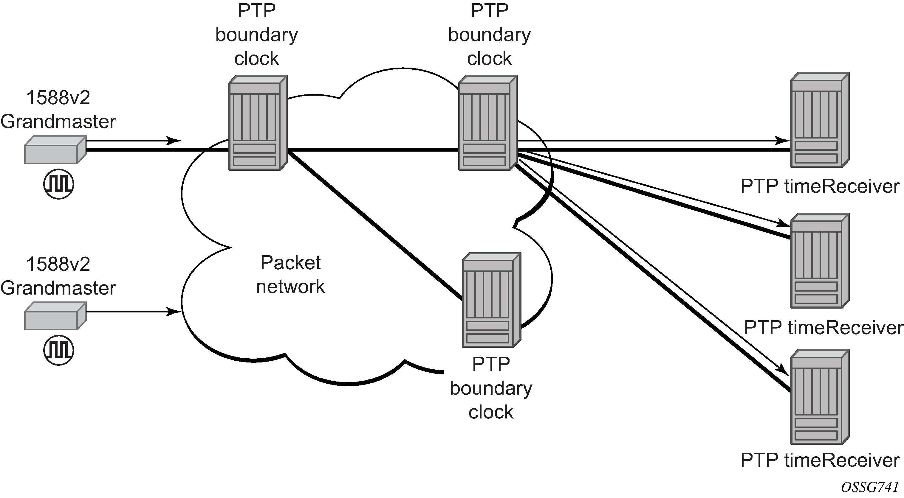
The following figure shows how network synchronization is commonly distributed in a hierarchical PTP topology at the physical layer.
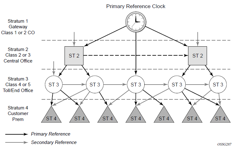
The architecture shown in the preceding figure provides the following benefits:
It limits the need for high quality clocks at each network element and only requires that they reliably replicate input to remain traceable to its reference.
It uses reliable physical media to provide transport of the timing signal. It does not consume any bandwidth and requires limited additional processing.
The synchronization network is designed so a clock always receives timing from a clock of equal or higher stratum or quality level. This ensures that if an upstream clock has a fault condition (for example, loses its reference and enters a holdover or free-run state) and begins to drift in frequency, the downstream clock will be able to follow it. For greater reliability and robustness, most offices and nodes have at least two synchronization references that can be selected in priority order (such as primary and secondary).
Further levels of resiliency can be provided by designing a capability in the node clock that will operate within prescribed network performance specifications without any reference for a specified timeframe. A clock operating in this mode is said to hold the last known state over (or holdover) until the reference lock is once again achieved. Each level in the timing hierarchy is associated with minimum levels of network performance.
Each synchronization-capable port can be independently configured to transmit data using the node reference timing. In addition, some TDM channels can use adaptive timing or loop timing.
Transmission of a reference clock through a chain of Ethernet equipment requires that all equipment supports Synchronous Ethernet. A single piece of equipment that is not capable of performing Synchronous Ethernet breaks the chain. Ethernet frames will still get through but downstream devices should not use the recovered line timing because it will not be traceable to an acceptable stratum source.
Central synchronization subsystem
The timing subsystem has a central clock located on the CPM. The timing subsystem performs several functions of the network element clock as defined by Telcordia (GR-1244-CORE) and ITU-T G.781 standards.
The central clock uses the available timing inputs to train its local oscillator. The number of timing inputs available to train the local oscillator varies per platform. The priority order of these references must be specified. This is an ordered list of inputs: (ref1, ref2). The CPM clock output can drive the clocking for all line cards in the system. The routers support selection of the node reference using Quality Level (QL) indications. The recovered clock will be able to derive its timing from one of the references available on that platform.
A logical model of the synchronization reference selection on 7210 SAS platforms shows how on 7210 SAS devices, the recovered clock is able to derive the timing from any of the following references:
synchronous Ethernet ports
1588v2/PTP timeReceiver port
See Synchronization options available on 7210 SAS platforms for information about the synchronization options supported by each 7210 SAS platform.
The following figure shows the synchronization reference selection available for the 7210 SAS platforms.
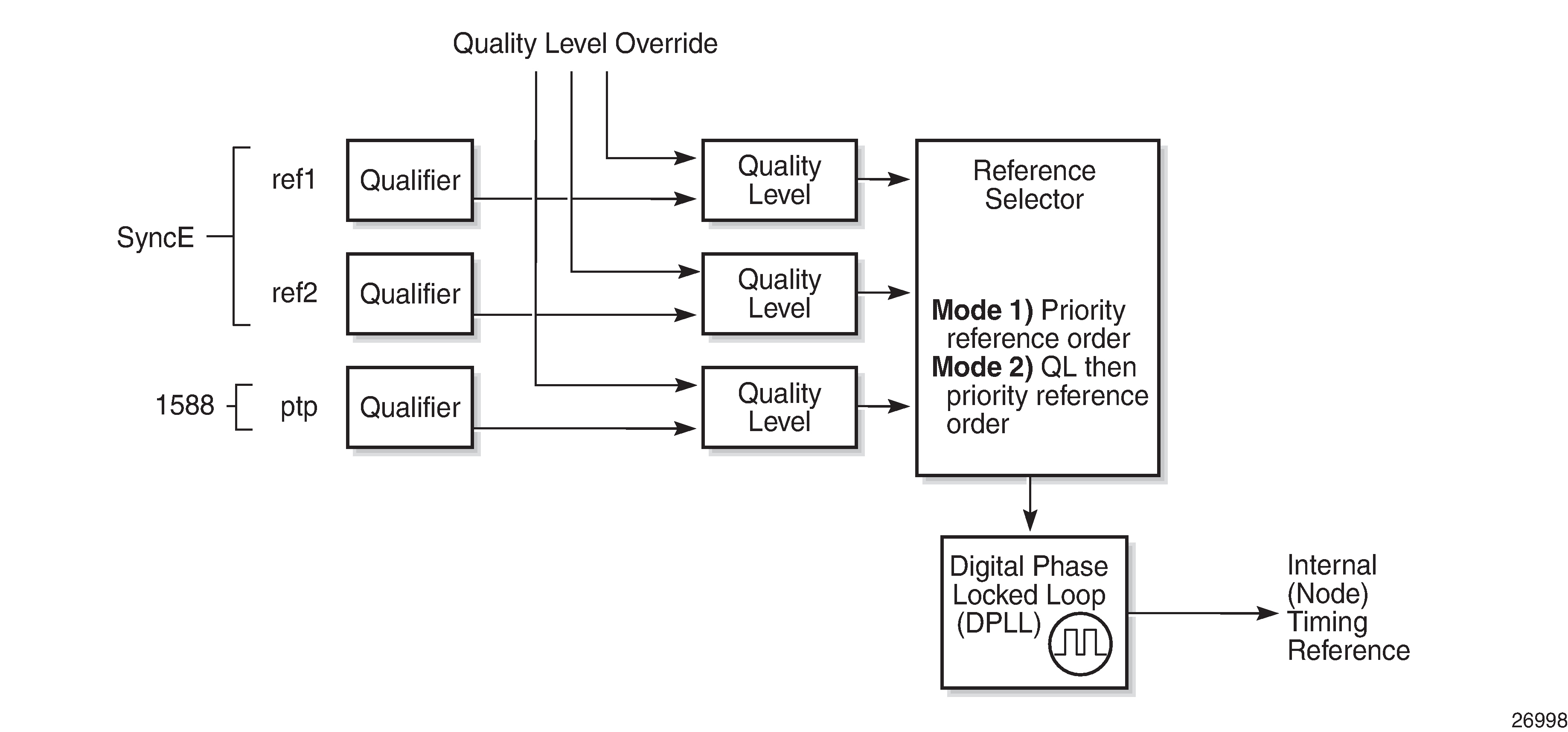
When Quality Level (QL) selection mode is disabled, the reversion setting controls when the central clock can reselect a previously failed reference.
The following table describes the selection followed for two references in both revertive and non-revertive modes.
Status of reference A |
Status of reference B |
Active reference non-revertive case |
Active reference revertive case |
|---|---|---|---|
OK |
OK |
A |
A |
Failed |
OK |
B |
B |
OK |
OK |
B |
A |
OK |
Failed |
A |
A |
OK |
OK |
A |
A |
Failed |
Failed |
Holdover |
Holdover |
OK |
Failed |
A |
A |
Failed |
Failed |
Holdover |
Holdover |
Failed |
OK |
B |
B |
Failed |
Failed |
Holdover |
Holdover |
OK |
OK |
A or B |
A |
Synchronization options available on 7210 SAS platforms
The following table lists the synchronization options supported on 7210 SAS platforms.
The 7210 SAS supports the ordinary clock in timeReceiver mode and the boundary clock. The boundary clock and ordinary clock timeReceiver can be used for both frequency and time distribution and recovery. The 7210 SAS does not support ordinary clock in timeTransmitter mode or peer-to-peer transparent clock.
Synchronization options |
7210 SAS platforms |
||||||
|---|---|---|---|---|---|---|---|
|
7210 SAS-D ETR |
7210 SAS-Dxp 12p ETR |
7210 SAS-Dxp 16p |
7210 SAS-Dxp 24p |
7210 SAS-K 2F1C2T |
7210 SAS-K 2F6C4T |
7210 SAS-K 3SFP+ 8C |
|
SyncE with SSM (SFP, SFP+, and 10G/XFP ports) |
✓ |
✓ |
✓ |
✓ |
✓1 |
✓1 |
✓ |
SyncE with fixed copper ports2 |
✓3 |
✓ |
✓ |
✓ |
✓1 |
✓1 |
✓ |
1588v2/PTP with port-based timestamps (both for frequency and time, also known as PTP pure mode) |
—4 |
|
|
|
✓5 |
✓5 |
✓6 |
1588v2/PTP with port-based timestamps (time only with SyncE used for frequency recovery, also known as PTP hybrid mode) |
✓ |
✓ |
|
|
✓ |
✓ |
✓ |
PTP end-to-end (E2E) transparent clock7 |
|||||||
|
PTP power profile (IEC/IEEE 61850-9-3 and C37.238-2017) |
✓ |
✓ |
|||||
Synchronization status messages (SSM)
Synchronous status messages are supported on devices that support Synchronous Ethernet.
SSM allows the synchronization distribution network to determine the quality level of the clock sourcing a specific synchronization trail and also allows a network element to select the best of multiple input synchronization trails. SSMs are defined for various transport protocols (including SONET/SDH, T1/E1, and Synchronous Ethernet), for interaction with office clocks (such as BITS or SSUs) and embedded network element clocks.
SSM allows equipment to autonomously provision and reconfigure (by reference switching) their synchronization references, while helping to avoid the creation of timing loops. These messages are particularly useful for synchronization re-configurations when timing is distributed in both directions around a ring.
Synchronous Ethernet
Traditionally, Ethernet-based networks employ a physical layer transmitter clock derived from an inexpensive +/-100ppm crystal oscillator and the receiver locks onto it. Because data is packetized and can be buffered, there is no need for long-term frequency stability or for consistency between frequencies of different links.
Synchronous Ethernet is a variant of the line timing that derives the physical layer transmitter clock from a high-quality frequency reference, replacing the crystal oscillator with a frequency source traceable to a primary reference clock. This change is transparent to the other Ethernet layers and does not affect their operation. The receiver at the far end of the link is locked to the physical layer clock of the received signal, and ensures access to a highly accurate and stable frequency reference. In a manner analogous to conventional hierarchical network synchronization, this receiver can lock the transmission clock of other ports to this frequency reference, and establish a fully time-synchronous network.
Unlike methods that rely on sending timing information in packets over an unclocked physical layer, Synchronous Ethernet is not affected by impairments introduced by higher levels of networking technology (packet loss, packet delay variation). The frequency accuracy and stability in Synchronous Ethernet typically exceeds networks with unsynchronized physical layers.
Synchronous Ethernet allows operators to gracefully integrate existing systems and future deployments into a conventional industry-standard synchronization hierarchy. The concept is analogous to SONET/SDH system timing capabilities. The operator can select any (optical) Ethernet port as a candidate timing reference. The recovered timing from this port is used to time the system (for example, the CPM locks to this provisioned reference selection). The operator then can ensure that all system output is locked to a stable traceable frequency source.
The SFP, XFP or SFP+ transceivers used with the SFP, XFP, and SFP+ ports must support Synchronous Ethernet.
See Synchronization options available on 7210 SAS platforms for information about Synchronous Ethernet support for each 7210 SAS platform.
Fixed copper ports using Synchronous Ethernet can be used as a candidate reference or for distribution of recovered reference. If the port is a fixed copper Ethernet port and in 1000BASE-T mode of operation, there is a dependency on the 802.3 link timing for the synchronous Ethernet functionality (see ITU-T G.8262). The 802.3 standard link timing states must align with the needed direction of synchronous Ethernet timing flow. When a fixed copper Ethernet port is specified as an input reference for the node or when it is removed as an input reference for the node, 802.3 link autonegotiation is triggered to ensure that the link timing aligns correctly.
The SSM of synchronous Ethernet uses an Ethernet OAM PDU that uses the slow protocol subtype. For a complete description of the format and processing, see ITU-T G.8264.
Clock source quality level definitions
This section describes the clock source quality levels identified for tracking network timing flow in accordance with the network deployment options defined in Recommendation G.803 and G.781. The Option I network is developed on the original European SDH model; Option II network is a network developed on the North American SONET model.
In addition to the QL values received over SSM of an interface, the standards define the following additional codes for internal use:
QL INVx is generated internally by the system if and when an unallocated SSM value is received, where x represents the binary value of this SSM. Within the SR OS, these independent values are assigned as the single value QL-INVALID.
QL FAILED is generated internally by the system if and when the terminated network synchronization distribution trail is in the signal fail state.
The internal quality level of QL-UNKNOWN is used to differentiate from a received QL-STU code, but is equivalent for the purposes of QL selection.
The following tables list the synchronization message coding and source priorities for SSM values received and transmitted on the port.
SSM value received on port |
Internal relative quality level |
|||
|---|---|---|---|---|
SDH interface SyncE interface in SDH mode |
SONET interface SyncE interface in SONET mode |
E1 interface |
T1 interface (ESF) |
|
0010 (prc) |
0001 (prs) |
0010 (prc) |
00000100 11111111 (prs) |
1. Best quality |
0000 (stu) |
00001000 11111111 (stu) |
2. |
||
0111 (st2) |
00001100 11111111 (ST2) |
3. |
||
0100 (ssua) |
0100 (tnc) |
0100 (ssua) |
01111000 11111111 (TNC) |
4. |
1101 (st3e) |
01111100 11111111 (ST3E) |
5. |
||
1000 (ssub) |
1000 (ssub) |
6. |
||
1010 (st3/eec2) |
00010000 11111111 (ST3) |
7. |
||
1011 (sec/eec1) |
1011 (sec) |
8. Lowest quality qualified in QL-enabled mode |
||
1100 (smc) |
00100010 11111111 (smc) |
9. |
||
00101000 11111111 (st4) |
10. |
|||
1110 (pno) |
01000000 11111111 (pno) |
11. |
||
1111 (dnu) |
1111 (dus) |
1111 (dnu) |
00110000 11111111 (dus) |
12. |
Any other |
Any other |
Any other |
N/A |
13. QL_INVALID |
14. QL-FAILED |
||||
15. QL-UNC |
||||
Internal relative quality level |
SSM values to be transmitted by interface of type |
|||
|---|---|---|---|---|
SDH interface SyncE interface in SDH mode |
SONET interface SyncE interface in SONET mode |
E1 interface |
T1 interface (ESF) |
|
1. Best quality |
0010 (prc) |
0001 (PRS) |
0010 (prc) |
00000100 11111111 (PRS) |
2. |
0100 (ssua) |
0000 (stu) |
0100 (ssua) |
00001000 11111111 (stu) |
3. |
0100 (ssua) |
0111 (st2) |
0100 (ssua) |
00001100 11111111 (st2) |
4. |
0100 (ssua) |
0100 (tnc) |
0100 (ssua) |
01111000 11111111 (tnc) |
5. |
1000 (ssub) |
1101 (st3e) |
1000 (ssub) |
01111100 11111111 (st3e) |
6. |
1000 (ssub) |
1010 (st3/eec2) |
1000 (ssub) |
00010000 11111111 (st3) |
7. |
1011 (sec/eec1) |
1010 (st3/eec2) |
1011 (sec) |
00010000 11111111 (st3) |
8. Lowest quality qualified in QL-enabled mode |
1011 (sec/ eec1) |
1100 (smc) |
1011 (sec) |
00100010 11111111 (smc) |
9. |
1111 (dnu) |
1100 (smc) |
1111 (dnu) |
00100010 11111111 (smc) |
10. |
1111 (dnu) |
1111 (dus) |
1111 dnu |
00101000 11111111 (st4) |
11. |
1111 (dnu) |
1110 (pno) |
1111 (dnu) |
01000000 11111111 (pno) |
12. |
1111 (dnu) |
1111 (dus) |
1111 (dnu) |
00110000 11111111 (dus) |
13. QL_INVALID |
1111 (dnu) |
1111 (dus) |
1111 (dnu) |
00110000 11111111 (dus) |
14. QL-FAILED |
1111 (dnu) |
1111 (dus) |
1111 (dnu) |
00110000 11111111 (dus) |
15. QL-UNC |
1011 (sec/eec1) |
1010 (st3/eec2) |
1011 (sec) |
00010000 11111111 (st3) |
IEEE 1588v2 PTP
Precision Time Protocol (PTP) is only supported on the 7210 SAS-D ETR, 7210 SAS-Dxp 12p ETR, 7210 SAS-Dxp 16p, 7210 SAS-Dxp 24p, 7210 SAS-K 2F1C2T, 7210 SAS-K 2F6C4T, and 7210 SAS-K 3SFP+ 8C.
References to G.8275.1 and Ethernet encapsulation apply only to the 7210 SAS-Dxp 12p ETR, 7210 SAS-K 2F6C4T, and 7210 SAS-K 3SFP+ 8C.
PTP is a timing-over-packet protocol defined in the IEEE 1588v2 standard 1588 PTP 2008.
PTP may be deployed as an alternative timing-over-packet option to ACR. PTP provides the capability to synchronize network elements to a Stratum-1 clock or primary reference clock (PRC) traceable source over a network that may or may not be PTP-aware. PTP has several advantages over ACR. It is a standards-based protocol, has lower bandwidth requirements, can transport both frequency and time, and can potentially provide better performance.
The following is a list of the four basic types of PTP devices:
ordinary clock
boundary clock
end-to-end transparent clock
peer-to-peer transparent clock
See Synchronization options available on 7210 SAS platforms for more information about supported PTP device types on 7210 SAS platforms.
Peer clocks shows how the 7210 SAS communicates with peer 1588v2 clocks. These peers can be ordinary clock timeReceivers or boundary clocks. The communication can be based on either unicast IPv4 sessions transported through IP interfaces or Ethernet multicast PTP packets transported through an Ethernet port.
The following table describes IP/UDP unicast and multicast support for the 7210 SAS platforms.
Protocol |
IP/UDP unicast |
Ethernet multicast |
|---|---|---|
7210 SAS-D |
Yes8 |
No |
7210 SAS-Dxp 12p |
No |
Yes8 |
7210 SAS-Dxp 16p |
No |
Yes |
7210 SAS-Dxp 24p |
No |
Yes |
7210 SAS-K 2F1C2T |
Yes |
No |
7210 SAS-K 2F6C4T |
Yes |
Yes |
7210 SAS-K 3SFP+ 8C |
Yes |
Yes |
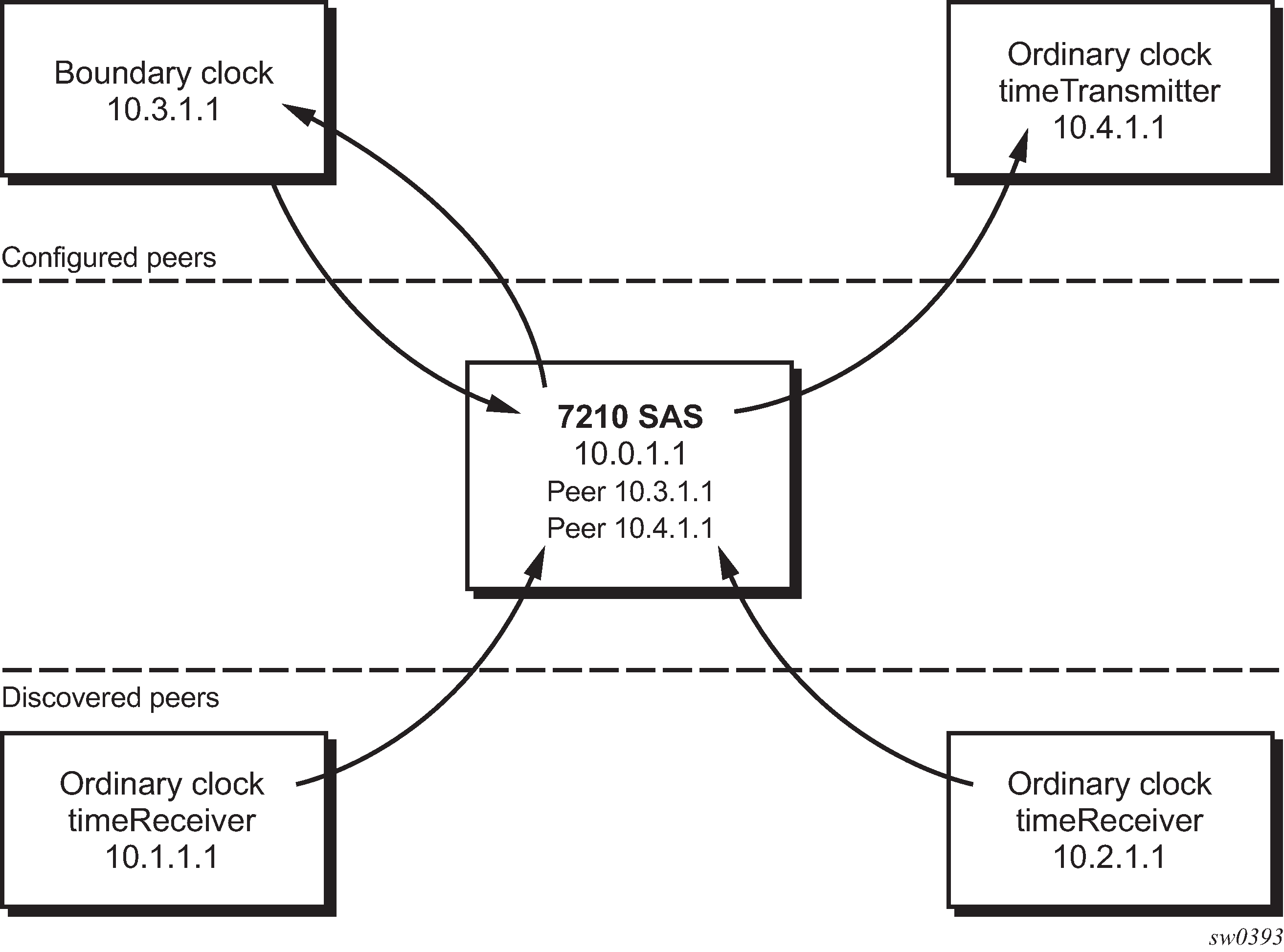
Unicast IP sessions support two types of peers: configured and discovered. The 7210 SAS operating as an ordinary clock timeReceiver or as a boundary clock must have configured peers for each PTP neighbor clock from which it may accept synchronization information. The 7210 SAS initiates unicast sessions with all configured peers. A 7210 SAS operating as a boundary clock accepts unicast session requests from external peers. If the peer is not configured, it is considered a discovered peer. The 7210 SAS can deliver synchronization information toward discovered peers (that is, timeReceivers).
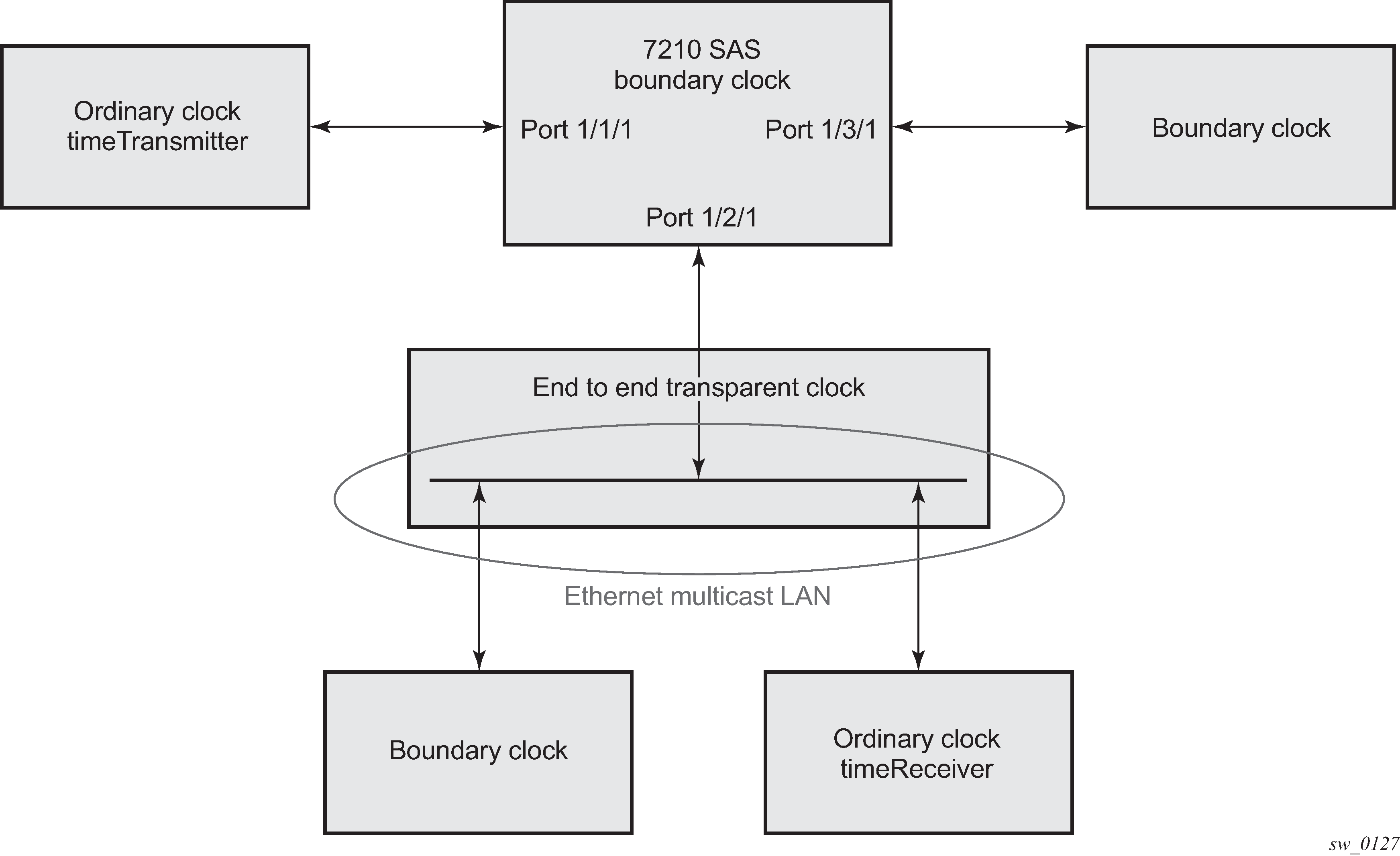
For Ethernet multicast operation, the node listens for and transmits PTP messages using the configured multicast MAC address. Neighbor clocks are discovered via messages received through an enabled Ethernet port. Ethernet multicast ports shows how the 7210 SAS supports only one neighbor PTP clock connecting into a single port.
The 7210 SAS does not allow for simultaneous PTP operations using both unicast IPv4 and Ethernet multicast. A change of profile to G.8275.1 or from G.8275.1 to another profile requires a reboot of the node.
The following figure shows the relationship of various neighbor clocks using unicast IP sessions to communicate with a 7210 SAS configured as a boundary clock with two configured peers.
The following figure shows the relationship of various neighbor clocks using multicast Ethernet sessions to a 7210 SAS configured as a boundary clock.
7210 SAS platforms do not support the ordinary clock timeTransmitter configuration.
The IEEE 1588v2 standard includes the concept of PTP profiles. These profiles are defined by industry groups or standards bodies that define the use of IEEE 1588v2 for specific applications.
The 7210 SAS currently supports three profiles. The following table lists PTP profile support for 7210 SAS platforms.
PTP profiles |
7210 SAS platforms |
||||||
|---|---|---|---|---|---|---|---|
|
7210 SAS-D ETR |
7210 SAS-Dxp 12p ETR |
7210 SAS-Dxp 16p |
7210 SAS-Dxp 24p |
7210 SAS-K 2F1C2T |
7210 SAS-K 2F6C4T |
7210 SAS-K 3SFP+ 8C |
|
IEEE 1588v2 (default profile) |
✓ |
✓ |
✓ |
✓ |
|||
ITU-T Telecom profile (G.82651) |
✓ |
✓ |
✓ |
✓ |
|||
|
ITU-T Telecom profile for time with full timing support (G.8275.1) |
✓ |
✓ |
✓ |
||||
| IEC/IEEE 61850-9-3 and C37.238-2017 profiles | ✓ | ✓ | |||||
When a 7210 SAS receives Announce messages from one or more configured peers or multicast neighbors, it executes a Best timeTransmitter Clock Algorithm (BTCA) to determine the state of communication between itself and the peers. The system uses the BTCA to create a hierarchical topology, allowing the flow of synchronization information from the best source (the grandmaster clock) out through the network to all boundary and timeReceiver clocks. Each profile has a dedicated BTCA.
If the profile setting for the clock is ieee1588-2008, the precedence order for the BTCA is as follows:
priority1
clock class
clock accuracy
PTP variance (offsetScaledLogVariance)
priority2
clock identity
steps removed from the grandmaster
The following table describes how the 7210 SAS sets its local parameters.
Parameter |
Value |
|---|---|
clockClass |
248 - the 7210 SAS is configured as a boundary clock 255 - the 7210 SAS is configured as an ordinary clock timeReceiver |
clockAccuracy |
FE - unknown |
offsetScaledLogVariance |
FFFF - not computed |
clockIdentity |
Chassis MAC address following the guidelines of section 7.5.2.2.2 of IEEE 1588-2008 |
If the profile setting for the clock is itu-telecom-freq (ITU G.8265.1 profile), the precedence order for the best timeTransmitter selection algorithm is the following:
clock class
PTSF (Packet Timing Signal Fail) - Announce Loss (miss 3 Announce messages or do not get an Announce message for 6 seconds)
priority
The following table describes how the 7210 SAS sets its local parameters.
Parameter |
Value |
|---|---|
clockClass |
80-110 - value corresponding to the QL out of the central clock of the 7210 SAS as per Table 1/G.8265.1 255 - the 7210 SAS is configured as an ordinary clock timeReceiver |
The ITU-T profile is for use in environments with only ordinary clock timeTransmitters and timeReceivers for frequency distribution.
If the profile setting for the clock is g8275dot1-2014, the precedence order for the best timeTransmitter selection algorithm is very similar to that used for the default profile. It ignores the priority1 parameter, includes a localPriority parameter, and includes the ability to force a port to never enter the timeReceiver state (master-only). The precedence is as follows:
clock class
clock accuracy
PTP variance (offsetScaledLogVariance)
priority2
localPriority
clock identity
steps removed from the grandmaster
The following table describes how the 7210 SAS sets its local parameters.
Parameter |
Value |
|---|---|
clockClass |
165 - the 7210 SAS is configured as a boundary clock and the boundary clock was previously locked to a grandmaster with a clock class of 6 248 - the 7210 SAS is configured as a boundary clock 255 - the 7210 SAS is configured as an ordinary clock timeReceiver |
clockAccuracy |
FE - unknown |
offsetScaledLogVariance |
FFFF - not computed |
clockIdentity |
Chassis MAC address following the guidelines of section 7.5.2.2.2 of IEEE 1588-2008 |
The 7210 SAS can support a limited number of configured peers (possible timeTransmitter or neighbor boundary clocks) and a limited number of discovered peers (timeReceivers).These peers use the unicast negotiation procedures to request service from the 7210 SAS clock. A neighbor boundary clock counts for two peers (both a configured and a discovered peer) toward the maximum limit.
On the 7210 SAS-D ETR, 7210 SAS-Dxp 12p ETR, 7210 SAS-K 2F1C2T, 7210 SAS-K 2F6C4T, and 7210 SAS-K 3SFP+ 8C, there are limits on the number of timeReceivers enforced in the implementation for unicast and multicast PTP timeReceivers. Contact your Nokia technical support representative for information about the specific unicast message limits related to PTP.
When PTP is configured, the PTP load must be monitored to ensure that the load does not exceed the capabilities (configured values) to ensure that sufficient CPU processing cycles are available for PTP. There are several commands that can be used for this monitoring, including show system cpu, which identifies the load of the PTP software process. If the ‟capacity usage” reaches 100%, the PTP software process on the 7210 SAS is at its limit of transmitting or receiving PTP packets.
Because the user cannot control the number of PTP messages received by the 7210 SAS over its Ethernet ports, the following statistics commands can be used to identify the source of the message load:
show system ptp statistics displays aggregate packet rates
show system ptp port and show system ptp port port-id [detail] display received packet rates
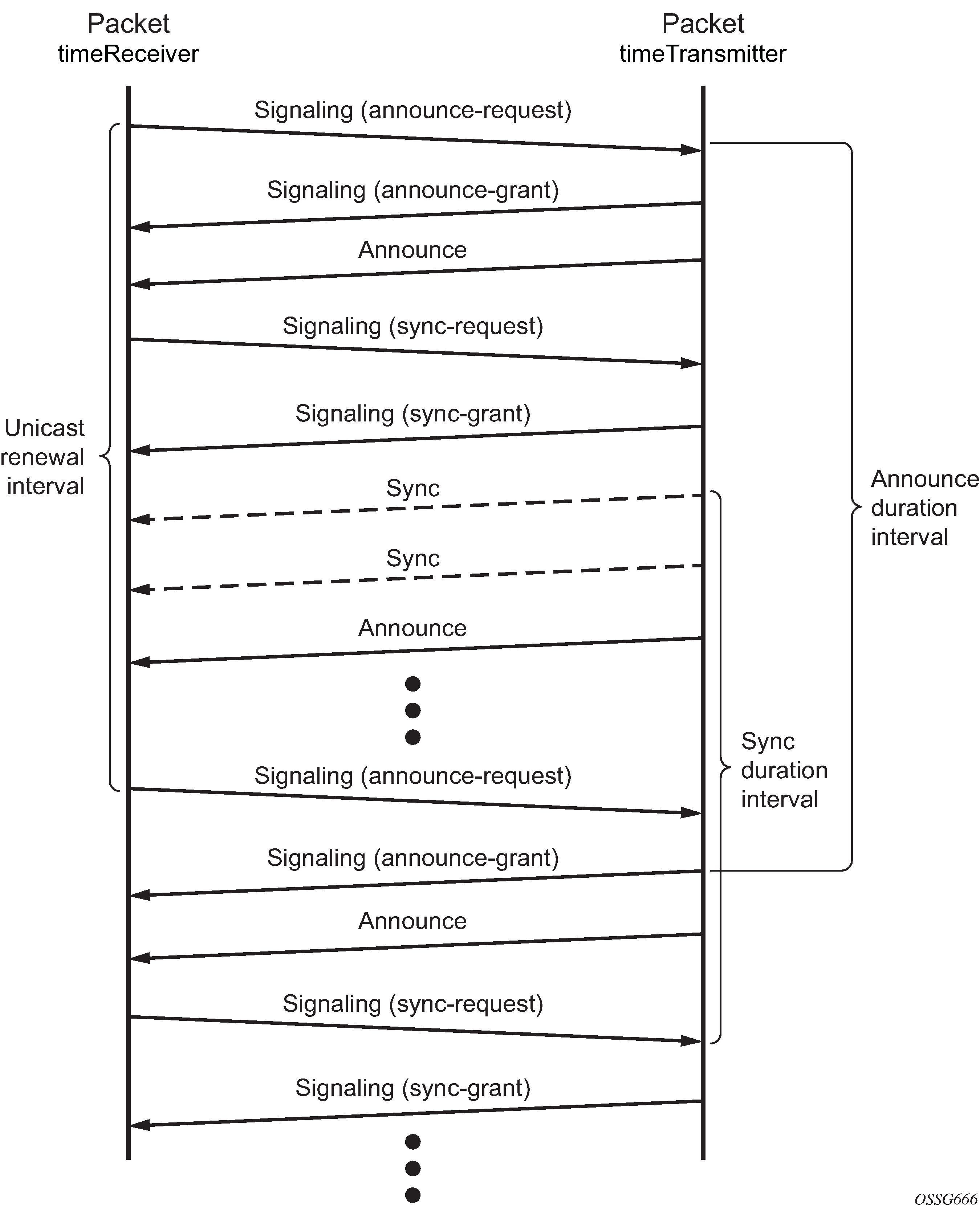
The following figure shows the unicast negotiation procedure performed between a timeReceiver and a peer clock that is selected to be the timeTransmitter clock. The timeReceiver clock will request Announce messages from all peer clocks but only request Sync and Delay_Resp messages from the clock selected to be the timeTransmitter clock.
PTP clock synchronization
The IEEE 1588v2 standard synchronizes the frequency and time from a timeTransmitter clock to one or more timeReceiver clocks over a packet stream. This packet-based synchronization can be over IP/UDP unicast or Ethernet multicast.
As part of the basic synchronization timing computation, event messages are defined for synchronization messaging between the PTP timeReceiver clock and PTP timeTransmitter clock. A one-step or two-step synchronization operation can be used; the two-step operation requires a follow-up message after each synchronization message.
The 7210 SAS-D ETR supports only two-step timeTransmitter port operation. All platforms can operate timeReceiver ports that receive from a one-step or two-step timeTransmitter port.
During startup, the PTP timeReceiver clock receives synchronization messages from the PTP timeTransmitter clock before a network delay calculation is made. Before any delay calculation, the delay is assumed to be zero. A drift compensation is activated after a number of synchronization message intervals occur. The expected interval between the reception of synchronization messages is user-configurable.
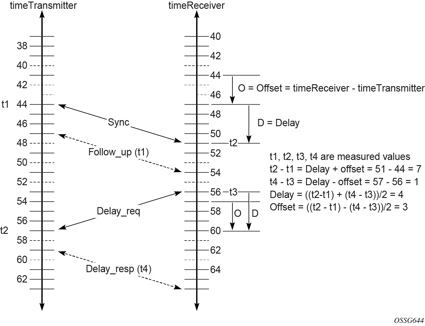
The following figure shows the basic synchronization timing computation between the PTP timeReceiver clock and PTP best timeTransmitter, as well as the offset of the timeReceiver clock referenced to the best timeTransmitter signal during startup.
When the IEEE 1588v2 standard is used for distribution of a frequency reference, the timeReceiver calculates a message delay from the timeTransmitter to the timeReceiver based on the timestamps exchanged. A sequence of these calculated delays contains information about the relative frequencies of the timeTransmitter clock and timeReceiver clock, but also includes a noise component related to the PDV experienced across the network. The timeReceiver must filter the PDV effects to extract the relative frequency data and then adjust the timeReceiver frequency to align with the timeTransmitter frequency.
When the IEEE 1588v2 standard is used for distribution of time, the 7210 SAS calculates the offset between the 7210 SAS time base and the external timeTransmitter clock time base based on the four timestamps exchanged. The 7210 SAS determines the offset adjustment, and between these adjustments, it maintains the progression of time using the frequency from the central clock of the node. This allows time to be maintained using a Synchronous Ethernet input source even if the IEEE 1588v2 communications fail. When using IEEE 1588v2 for time distribution, the central clock should, at a minimum, have the PTP input reference enabled.
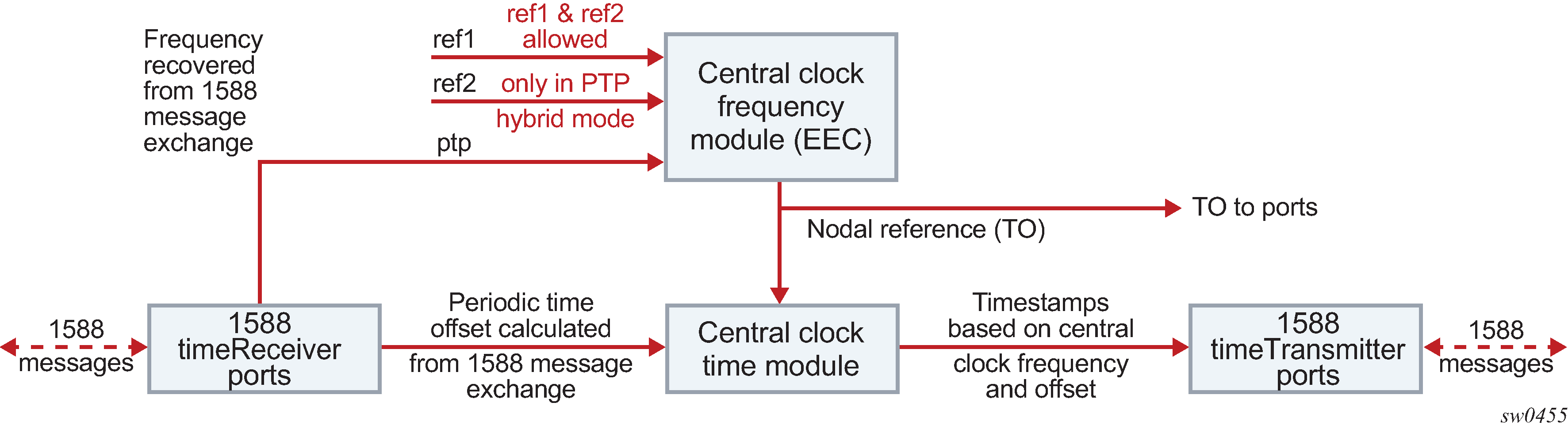
The following figure shows the logical model for using PTP/1588 for network synchronization.
Performance considerations
Although IEEE 1588v2 can be used on a network that is not PTP-aware, the use of PTP-aware network elements (boundary clocks) within the packet-switched network improves synchronization performance by reducing the impact of PDV between the grandmaster clock and the timeReceiver clock. In particular, when IEEE 1588v2 is used to distribute high-accuracy time, such as for mobile base station phase requirements, the network architecture requires the deployment of PTP awareness in every device between the grandmaster and the mobile base station timeReceiver.
In addition, performance is also improved by the removal of any PDV caused by internal queuing within the boundary clock or timeReceiver clock. This is accomplished with hardware that is capable of port-based timestamping, which detects and timestamps the IEEE 1588v2 packets at the Ethernet interface.
PTP message transparent forwarding
The ptp-hw-timestamp command is supported only on the 7210 SAS-Dxp 12p ETR, 7210 SAS-Dxp 16p, 7210 SAS-Dxp 24p, 7210 SAS-K 2F1C2T, 7210 SAS-K 2F6C4T, and 7210 SAS-K 3SFP+ 8C. On bootup, port-based hardware timestamping is enabled by default on all ports on the 7210 SAS-K 2F1C2T, 7210 SAS-K 2F6C4T, and 7210 SAS-K 3SFP+ 8C. It is disabled by default on the 7210 SAS-Dxp 12p ETR, 7210 SAS-Dxp 16p, and 7210 SAS-Dxp 24p. The correction field in the PTP IP/UDP messages and PTP Ethernet messages that are not addressed to the node are updated for the residence time of the packet in the node.
The ptp-hw-timestamp command must be enabled for the node to process locally-destined PTP packets.
Use the ptp-hw-timestamp command to disable port-based hardware timestamping on ports that transparently forward received PTP packets. See the 7210 SAS-D, Dxp, K 2F1C2T, K 2F6C4T, K 3SFP+ 8C Interface Configuration Guide for more information about the ptp-hw-timestamp command.
When PTP port-based hardware timestamping is disabled, the node does not update the correction field in PTP messages.
For example, to transparently forward PTP packets over MPLS tunnels that use access ports with SAPs to connect the PTP timeTransmitters or timeReceivers, you can use the ptp-hw-timestamp command to disable PTP port-based hardware timestamping on the access ports.
The configuration of port-based hardware timestamping on selective ports of the 7210 SAS-Dxp 12p ETR, 7210 SAS-Dxp 16p, 7210 SAS-Dxp 24p, 7210 SAS-K 2F1C2T, 7210 SAS-K 2F6C4T, and 7210 SAS-K 3SFP+ 8C platforms can be used for transparent PTP packet forwarding if PTP is enabled and used to time the node (that is, PTP messages are originated and terminated by the node acting as a PTP OC-timeReceiver or BC).
The following guidelines must be considered for transparent PTP packet forwarding:
To enable transparent PTP packet forwarding, use the configure>port>no ptp-hw-timestamp command to disable the feature on all ports that receive and forward IP-UDP and Ethernet PTP messages.
To enable transparent forwarding of PTP packets over MPLS tunnels on the 7210 SAS-K 2F6C4T and 7210 SAS-K 3SFP+ 8C, PTP hardware port-based timestamping must be disabled on the access ports where SAPs are configured. These access ports connect to either PTP timeTransmitter or PTP timeReceivers that need to establish PTP sessions and exchange PTP messages transparently. Disabling PTP hardware port-based timestamping is not required on network ports where the MPLS tunnels originate and terminate. As a result, these network ports can be used for PTP packet exchange when the node is a PTP boundary clock or an ordinary clock timeReceiver. If the requirement is to forward PTP packets transparently when MPLS uplinks are not used or when a hybrid port with a SAP is used, PTP hardware port-based timestamping must be disabled on the access port and hybrid port.
PTP capabilities
PTP messages are supported through IPv4 unicast with a fixed IP header size. The following table describes the supported message rates for timeReceiver and timeTransmitter states. The ordinary clock can only be used in the timeReceiver state. The boundary clock can be in both of these states.
Support message |
timeReceiver clock |
timeTransmitter clock |
|
|---|---|---|---|
Request rate |
Grant rate |
||
Min |
Max |
||
Announce |
1 packet every 2 seconds |
1 packet every 2 seconds9 |
1 packet every 2 seconds9 |
Sync |
User-configurable with an option to configure 8/16 packets per second |
8 packets/second9 |
16 or 64 packets/second9 |
Delay_Resp |
User-configurable with an option to configure 8/16 packets per second |
8 packets/second9 |
16 or 64 packets/second9 |
Duration |
300 seconds |
1 second |
1000 seconds |
State and statistics data for each timeTransmitter clock are available to assist in the detection of failures or unusual situations.
PTP ordinary timeReceiver clock for frequency
Traditionally, only clock frequency is required to ensure smooth transmission in a synchronous network. The PTP ordinary clock with timeReceiver capability on the 7210 SAS provides another option to reference a Stratum-1 traceable clock across a packet switched network. The recovered clock can be referenced by the internal SSU and distributed to all slots and ports.
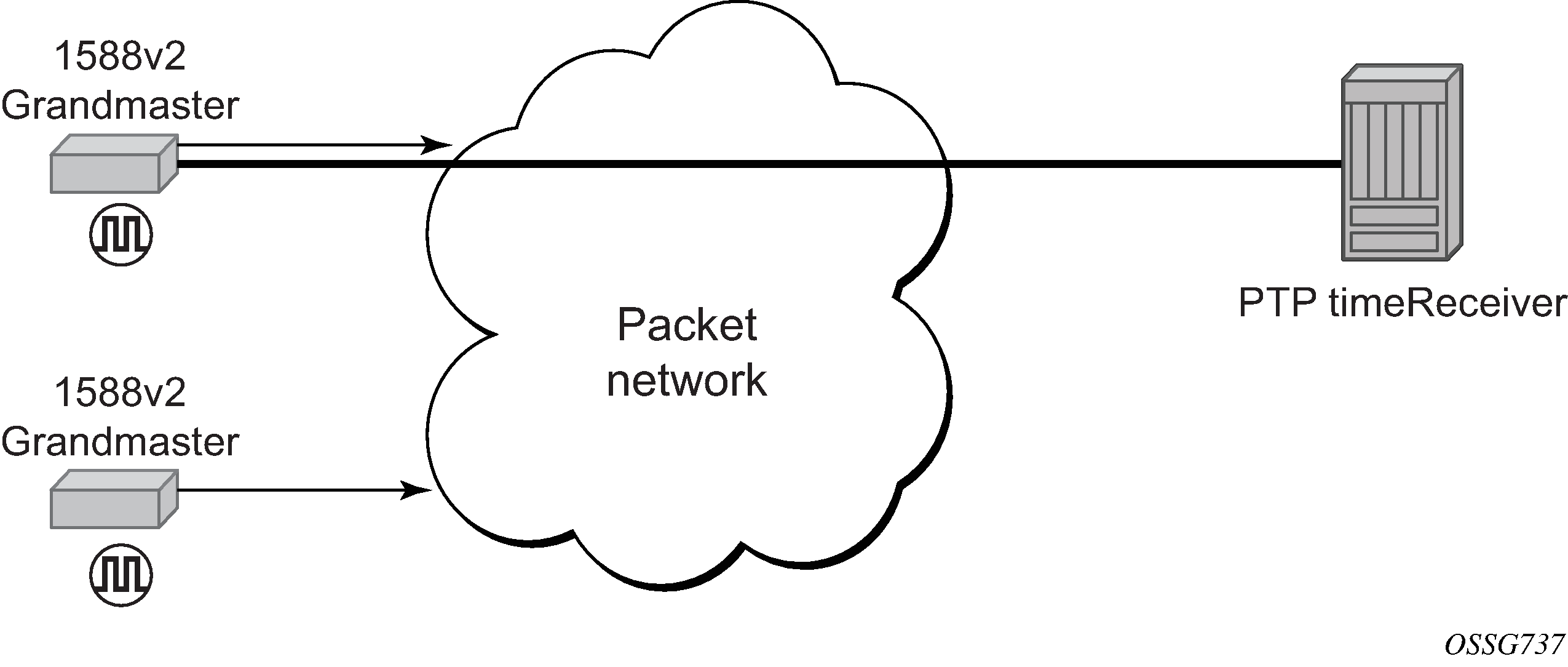
The following figure shows a PTP ordinary timeReceiver clock network configuration.
PTP boundary clock for frequency and time
Although IEEE 1588v2 can function across a packet network that is not PTP-aware, performance may be unsatisfactory and unpredictable. PDV across the packet network varies with the number of hops, link speeds, utilization rates, and the inherent behavior of routers. By using routers with boundary clock functionality in the path between the grandmaster clock and the timeReceiver clock, one long path over many hops is split into multiple shorter segments, allowing better PDV control and improved timeReceiver performance. This allows PTP to function as a valid timing option in more network deployments and allows for better scalability and increased robustness in certain topologies, such as rings.
Boundary clocks can simultaneously function as a PTP timeReceiver of an upstream grandmaster (ordinary clock) or boundary clock, and as a PTP timeTransmitter of downstream timeReceivers (ordinary clock) or boundary clocks. The time scale recovered in the timeReceiver side of the boundary clock is used by the timeTransmitter side of the boundary clock. This allows time across the boundary clock.
The following figure shows routers with boundary clock functionality in the path between grandmaster and the timeReceiver clock.
IEC/IEEE 61850-9-3 and C37.238-2017
The 7210 SAS supports IEC/IEEE 61850-9-3 and the C37.238-2017 extension, which are profiles that allow PTP to act as a timing source in power utility networks.
The IEC/IEEE 61850-9-3 and C37.238-2017 profiles support only Ethernet encapsulation with multicast addressing. Both profiles use the peer delay mechanism instead of the delay-request and response mechanism.
When configured for IEC/IEEE 61850-9-3 or C37.238-2017, the 7210 SAS can operate as a boundary clock and supports recovery of frequency as well as time of day or phase.
Synchronous Ethernet is recommeded to be used for frequency recovery when using PTP power profile for accurate phase and time recovery.
The IEC/IEEE 61850-9-3 and C37.238-2017 profiles have the following characteristics:
- The default domain setting is 0 for IEC/IEEE 61850-9-3 and 254 for C37.238-2017; the allowed range is 0 to 255.
- One-step clock operation is supported on the 7210 SAS without the need for follow-up messages.
-
Can operate timeReceiver ports that receive from a one-step or two-step timeTransmitter port.
- Only Ethernet encapsulation with multicast frames is supported with this profile.
- When Ethernet encapsulation is used, virtual local area network (VLAN) tags within Ethernet frames carrying PTP messages are not supported. When a PTP clock receives a PTP message within a frame containing a VLAN tag, it discards this frame.
- Synchronization messages, Announce messages, and peer delay messages are sent, by default, at the rate of 1 packet/s.
- By default, the priority1 and priority2 values are set to 128 when the clock-type is boundary. The priority values can be configured to be between 0 and 255.
The C37.238-2017 profile uses the IEEE_C37_238 TLV in Announce messages between the parent and slave clocks. This TLV includes the grand master clock ID and the total time inaccuracy. Each clock in the chain adds its own inaccuracy to the total time inaccuracy, which gives the ultimate slave clock an estimate of the inaccuracy over the entire path.
When acting as a boundary clock, the system receives the total time inaccuracy from the parent clock and adds its own time inaccuracy, then sends out a TLV with the updated total time inaccuracy. The user can change the default value for a boundary clock with the time-inaccuracy-override command.
See the IEC/IEEE 61850-9-3 standard and the C37.238-2017 extension for more information.
Configuration guidelines and restrictions for PTP
The following configuration guidelines and restrictions apply for PTP:
The PTP timeReceiver capability is available on all the ports on the 7210 SAS-D ETR, 7210 SAS-Dxp 12p ETR, 7210 SAS-Dxp 16p, 7210 SAS-Dxp 24p, 7210 SAS-K 2F1C2T, 7210 SAS-K 2F6C4T, and 7210 SAS-K 3SFP+ 8C.
The 7210 SAS-D ETR, 7210 SAS-Dxp 12p ETR, 7210 SAS-Dxp 16p, 7210 SAS-Dxp 24p, 7210 SAS-K 2F1C2T, 7210 SAS-K 2F6C4T, and 7210 SAS-K 3SFP+ 8C use CPU processing cycles for frequency and time recovery.
On the 7210 SAS-D ETR, 7210 SAS-Dxp 12p ETR, 7210 SAS-Dxp 16p, and 7210 SAS-Dxp 24p, Nokia highly recommends that PTP be used only in hybrid mode. Hybrid mode allows users to use reduced PTP packet rates and to scale better while using syncE for frequency reference.
On the 7210 SAS-D ETR, use of both PTP and SyncE as a reference simultaneously is not allowed. Either PTP or SyncE can be configured as a reference but not both at the same time.
On 7210 SAS devices, only a single profile (IEEE 1588v2, G.8265.1, or G.8275.1), IEC/IEEE 61850-9-3-2016, or C37.238-2017 can be enabled for all PTP communications (both toward its timeTransmitter and timeReceivers connected to it) at a time.
The PTP G.8275.1 profile is only supported on the 7210 SAS-Dxp 12p ETR, 7210 SAS-K 2F6C4T, and 7210 SAS-K 3SFP+ 8C. The following restrictions apply to the use of the G.8275.1 PTP profile:
The delay and sync requests are set to 16 pps by default and are not configurable.
The announce rate is set to 8 pps by default and is not configurable.
A change of profile to G.8275.1 or from G.8275.1 to another profile requires a reboot of the node.
Only a single multicast timeReceiver is supported per port.
PTP with Ethernet encapsulation is only supported with the G.8275.1 profile, IEC/IEEE 61850-9-3, and C37.238-2017 profiles.
PTP over IP encapsulation is not supported with the G.8275.1, IEC/IEEE 61850-9-3, and C37.238-2017 profiles. It is only supported with the IEEE 1588v2 and G.8265.1 profiles.
When changing the clock-type to or from a boundary clock on the 7210 SAS-K 2F1C2T, 7210 SAS-K 2F6C4T, and 7210 SAS-K 3SFP+ 8C, the node must be rebooted for the change to take effect. Ensure that measures are taken to minimize service disruption during the reboot process.
On the 7210 SAS-K 2F6C4T and 7210 SAS-K 3SFP+ 8C, to enable PTP hybrid mode when using the IEEE profile, the user must execute the command config>system>ptp>clock>freq-source ssu. To enable pure PTP mode, the user must execute the command config>system>ptp>clock>freq-source ptp. A change of value from ssu to ptp, or the other way around, requires a reboot of the node after the configuration changes are saved for the change to take effect.
On the 7210 SAS-Dxp 12p ETR, 7210 SAS-K 2F6C4T, and 7210 SAS-K 3SFP+ 8C, when the profile is set to G8275.1, the software automatically sets the freq-source to ssu. The user is not required to explicitly configure this setting.
On the 7210 SAS-D ETR, port-based timestamping is enabled for all PTP packets by default when PTP is enabled.
When PTP is enabled, PTP packets are not forwarded transparently through the node, regardless of the service used and whether PTP is configured as a system clock reference. If PTP is enabled, to enable transparent PTP forwarding again, disable PTP, save the configuration, and reboot the node.
On the 7210 SAS-Dxp 12p ETR, 7210 SAS-Dxp 16p, and 7210 SAS-Dxp 24p, port-based timestamping is disabled for all PTP packets by default. To enable PTP port-based timestamps, the user must explicitly enable PTP timestamping on the required ports.
When PTP is enabled, PTP packets are not forwarded transparently through the node, regardless of the service used and whether PTP is configured as a system clock reference. If PTP is enabled, to enable transparent PTP forwarding again, disable PTP port-based timestamping for the applicable ports.
On the 7210 SAS-K 2F1C2T, 7210 SAS-K 2F6C4T, and 7210 SAS-K 3SFP+ 8C, port-based timestamping is enabled for all PTP packets by default:
When port-based timestamping is enabled on all ports, PTP packets are not forwarded transparently through the node, regardless of the service used and whether PTP is configured as a system clock reference. To enable transparent PTP forwarding, disable port-based timestamping on the port.
Regardless of whether PTP is enabled (configure>sync-if-timing>ptp>no shutdown) or disabled (configure>sync-if-timing>ptp>shutdown), the timestamp value stored in the correction field (CF) is updated for all PTP packets that are in transit through the node. This affects all PTP packets that are not originated or terminated on the node.
See PTP message transparent forwarding for more information about enabling transparent forwarding.
Configuration to change reference from SyncE to PTP on 7210 SAS-D ETR
The following are the configuration steps to change reference from SyncE to PTP. This procedure is required only on 7210 SAS-D ETR nodes.
-
Run the following commands to configure standalone PTP as a reference.
configure >system >ptp >no shutdown

config> system> sync-if-timing> begin
ptp
no shutdown
exit
ref-order ptp [Must be configured]

config> system> sync-if-timing> commit
After the preceding commands are run, the frequency and time are provided by PTP only.
-
Run the following commands to change the reference to syncE.
config> system> sync-if-timing> begin
ptp
shutdown
exit

config> system> sync-if-timing> commit

config> system> sync-if-timing> begin
ref1
source-port 1/1/10
no shutdown
exit

ref2
source-port 1/1/11
no shutdown
exit

ref-order ref1 ref2   --------> Or, the ref-order you want [But Must be configured]

    revert    ---------------------> If you want ref-order you have setup to take
effect

ql-selection -------------------> Optional, if we need Quality to be considered.

config> system> sync-if-timing> commit
After the preceding commands are run, the frequency is provided by SyncE and TOD is provided by PTP [configure>system>ptp>no shutdown]. This is called PTP Hybrid mode.
-
Run the following commands to revert to standalone PTP from SyncE.
config> system> sync-if-timing> begin
ref1
source-port 1/1/10   --------------------> Not Required if port is already
                                           configured, but in admin down state
shutdown
exit

ref2
source-port 1/1/11   --------------------> Not Required if port is already
                                           configured, but in admin down state
shutdown
exit

config> system> sync-if-timing> commit

config> system> sync-if-timing> begin
ptp
no shutdown
exit

ref-order ptp [Must be configured]

config> system> sync-if-timing> commit
Now the frequency and time are provide by PTP (config>system>ptp>no shutdown) only. This is standalone PTP mode.
Link Layer Discovery Protocol (LLDP)
The IEEE 802.1ab Link Layer Discovery Protocol (LLDP) is a unidirectional protocol that uses the MAC layer to transmit specific information about the capabilities and status of the local device. The LLDP can send as well as receive information from a remote device stored in the related MIB (or MIBs).
The LLDP does not contain a mechanism to solicit information received from other LLDP agents or to confirm the receipt of information. However, LLDP provides the flexibility to enable a transmitter and receiver separately, and the following LLDP agent configurations are allowed:
only transmit information
only receive information
transmit and receive information
The information fields in each LLDP frame are contained in an LLDP Data Unit (LLDPDU) as a sequence of variable length information elements. Each information element includes Type, Length, and Value fields (TLVs):
Type indicates the nature of information being transmitted.
Length indicates the length of the information string in octets.
Value is the actual information that is transmitted. (For example, a binary bit map or an alphanumeric string that can contain one or more fields).
Each LLDPDU contains four mandatory TLVs and optional TLVs selected by the Network Management. The following is the format of an LLDPDU:
Chassis ID TLV
Port ID TLV
Time To Live (TTL) TLV
zero or more optional TLVs, depending on the maximum size of the LLDPDU allowed
End of LLDPDU TLV
A concatenated string formed by the Chassis ID TLV and the Port ID TLV is used by a recipient to identify an LLDP port or agent. The combination of the Port ID and Chassis ID TLVs remains unchanged until the port or agent is operational.
The TTL field of a Time-To-Live TLV can be a zero or non-zero value. A zero TTL field value notifies the receiving LLDP agent to immediately discard all information related to sending LLDP agent. A non-zero TTL field value indicates the time duration for which the receiving LLDP agent should retain the information of the sending LLDP agent. The receiving LLDP agent discards all information related to the sending LLDP agent after the time interval indicated in the TTL field is complete.
A TTL zero value is used to signal that the sending LLDP port has initiated a port shutdown procedure.
The End Of LLDPDU TLV indicates the end of the LLDPDU.
The following information is included in the protocol as defined by the IEEE 802.1ab standard:
Connectivity and management information about the local station to adjacent stations on the same IEEE 802 LAN is advertised.
Network management information from adjacent stations on the same IEEE 802 LAN is received.
It operates with all IEEE 802 access protocols and network media.
Network management information schema and object definitions suitable for storing connection information about adjacent stations is established.
It supports compatibility with a number of MIBs.
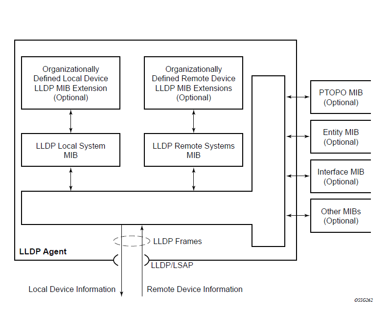
The following figure shows the LLDP internal architecture for a network node.
To detect and address network problems and inconsistencies in the configuration, the network operators can discover the topology information using LLDP. The standard-based tools address the complex network scenarios where multiple devices from different vendors are interconnected using Ethernet interfaces.
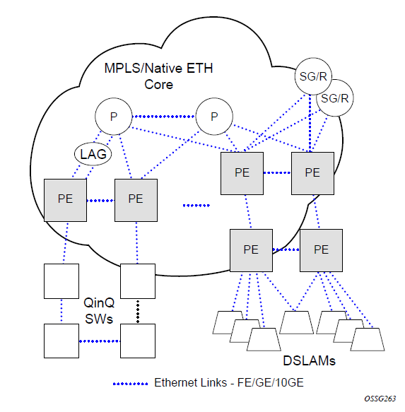
The following figure shows an MPLS network that uses Ethernet interfaces in the core, or as an access or handoff interface to connect to different kinds of Ethernet-enabled devices such as service gateway and routers, QinQ switches, DSLAMs, or customer equipment.
The topology information of the network in the following figure can be discovered if IEEE 802.1ab LLDP is running on each of the Ethernet interfaces in the network.
System resource allocation
This section describes system resource allocation.
Allocation of ingress internal TCAM resources
The system statically allocates ingress TCAM resources for use by SAP ingress QoS classification, SAP ingress access control lists (ACLs), identifying and sending CFM OAM packets to CPU for local processing, and so on. The resource allocation is not user-configurable. With the introduction of new capabilities such as IPv6 classification, UP MEP support, and G8032-fast-flood, the static allocation of resources by software does not meet requirements of customer who need to use different features.
The user can allocate a fixed amount of resources per system for QoS, ACLs, CFM/Y.1731 MEPs, and other features. Of these, some parameters are boot-time and others are run-time. A change in the current value of the parameter that is designated boot-time needs a reboot of the node before the new value takes effect. Change in the current value of the parameter that is designated run-time takes effect immediately if the software determines resources are available for use to accommodate the change.
During bootup, the system reads the resource profile parameters and allocates resources to features in the order they appear in the configuration file.
Because resources are shared, the user must ensure that the sum total of such resources does not exceed the limit supported by the IMM or node. If the system determines that it cannot allocate the requested resources, the feature is disabled. For example, if the system determines that it cannot allocate resources for g8032-fast-flood, it disables the feature from use and G8032 eth-rings will not be able to use fast-flood mechanisms). Another example is the case where the system determines that it cannot allocate resources for IPv4-based SAP Ingress ACL classification, the system will not allow users to use IPv4-based SAP ingress ACL classification feature and fails the configuration when it comes upon the first SAP in the configuration file that uses an IPv4-based SAP ingress ACL policy.
For boot-time parameters, such as g8032-fast-flood-enable, the user must ensure that the configured services match the resources allocated. If the system determines that it cannot allocate resources to services, it fails the configuration file at the first instance where it encounters a command to which resources cannot be allocated. The available resources can be allocated to different features.
For ACL and QoS resources, the user has the option to allocate resources to limit usage per feature, regardless of the match criteria used. The sum of all resources used for different SAP ingress classification match-criteria is limited by the amount of resources allocated for SAP ingress classification. The user can also allocate resources by specific match criteria. The user can enable any supported match criteria and associate a fixed amount of resources with each match criteria in fixed sizes; the chunk size is dependent on the platform.
The system allocates resources based on the order of appearance in the configuration file, and fails any match criteria if the system does not have any more resources to allocate. In addition, the max keyword can be used to indicate that the system needs to allocate resources when they are first required, as long as the maximum amount of resources allocated for that feature is not exceeded or the maximum amount of resources available in the system is not exceeded. The 7210 SAS platforms allocate resources to each feature and match-criteria in fixed-size chunks.
The no form of the command disables the use of corresponding match criteria. During runtime, the command succeeds, if no SAPs are currently using the criteria. Similarly, reduction of resources from the current value to a lower value succeeds, if no SAPs are currently using the criteria.
If the system successfully runs the no command, it frees up resources used by the chunk or slice and make the resources, or the entire chunk/slice, available for use by other features. Before deallocating resources, the software checks if a service object is using the resource and fails the command if the object is in use. If resources are in use, they can be freed up by deleting a SAP, removing a policy association with a SAP, deleting a MEP, and so on. Some commands under the system resource-profile context do not take effect immediately and require a system reboot before the change occurs and resources are freed. The following is the handling of freed resources:
If some entries in a slice are freed, they are made available for use by other SAPs using the same feature to which the chunk is allocated.
If an entire chunk is freed, it is returned to the system free pool for possible use by other features.
The no form of the commands that are designated as boot-time does not take effect immediately. It takes effect after the reboot. Before reboot, it is the user’s responsibility to free up resources required for use by the feature that has been enabled to take effect after the reboot. Not doing so results in failure when the configuration file is executed on boot up.
See the CLI and feature description chapters in the appropriate 7210 SAS platform user guide for more information about CLI commands and features that use system resource allocation.
Allocation of egress internal TCAM resources
Before the introduction of new capabilities, such as IPv6 match criteria, the system allocated egress TCAM resources on bootup for use by different criteria in SAP egress access control lists (ACLs) and other purposes; the resource allocation was not user configurable. With the introduction of new capabilities, such as IPv6 match criteria in egress, the static allocation of resources by software may not meet customer requirements if they want to use different features. Therefore, to facilitate user configuration and resource allocation in accordance with user needs, the ingress internal TCAM resource allocation capabilities have been extended to include the egress internal TCAM resources.
For information about specific CLI commands and features that use system resource allocation, see the CLI command and feature descriptions in the appropriate 7210 SAS software user manuals.
The commands in the config>system>resource-profile context, which require a reboot to take effect, are read and implemented by the system only during bootup. These commands do not take effect if the exec command is used to run the configuration file.
System resource allocation examples
On the 7210 SAS-K 2F1C2T, 7210 SAS-K 2F6C4T, and 7210 SAS-K 3SFP+ 8C, resources must be allocated among SAP ingress QoS and ingress ACLs. Users do not need to further allocate resources individually for MAC and IPv4 or IPv6 criteria.
The qos-sap-ingress-resource and acl-sap ingress commands under the system>resource-profile>ingress-internal-tcam context allocate resources to ingress QoS and ingress ACLs:
On the 7210 SAS-D and 7210 SAS-Dxp, resources are allocated in slices with 256 entries per slice.
On the 7210 SAS-K 2F1C2T and 7210 SAS-K 2F6C4T, resources are allocated with 510 entries per slice.
On the 7210 SAS-K 3SFP+ 8C, resources are allocated with 192 entries per slice.
The acl-sap egress command in the system>resource-profile>egress-internal-tcam context allocates resources to egress ACLs:
On the 7210 SAS-D and 7210 SAS-Dxp, resources are allocated in slices with 128 entries per slice.
On the 7210 SAS-K 2F1C2T and 7210 SAS-K 2F6C4T, resources are allocated with 510 entries per slice.
On the 7210 SAS-K 3SFP+ 8C, resources are allocated with 180 entries per slice.
1
config> system> resource-profile...
...
   acl-sap-ingress 3
      mac-match-enable max
      ipv4-match-enable 1
      no ipv6_128-ipv4-match-enable
      no ipv6_64-only-match-enable
   exit
...
In the preceding CLI example, the system performs the following actions:
-
3 chunks are allocated for use by the SAP ingress ACL entries.
-
1 chunk is allocated for use by SAP ingress ACL entries that use ipv4-criteria. The system fails the configuration when the number of ACL entries using ipv4-criteria exceeds the configured limit (that is, the system does not allocate in excess of the configured limit of 1 chunk).
-
A chunk is allocated for use by SAP ingress ACL entries that use mac-criteria. After the max keyword is specified, the system allocates 1 chunk for use when an ingress ACL policy (with mac-criteria entries defined) is associated with a SAP. The system can allocate up to 2 chunks because the max keyword is used. More chunks are allocated when the user configures a SAP that uses mac-criteria and all entries in the allocated chunks are used up. The system fails the configuration if the number of ACL entries with mac-criteria exceeds the limit of 2 chunks allocated to SAP ingress ACL match (that is, the system does not allocate in excess of the configured limit of 3; up to 2 chunks of the configured 3 chunk limit are allocated to mac-criteria and 1 chunk is allocated to ipv4-criteria).
-
The system fails a user attempt to use SAP ingress ACLs with IPv6 match criteria (and other combinations listed in the preceding list items), because the user has disabled these criteria.
2
config> system> resource-profile>ingress-internal-tcam>
...
acl-sap-ingress  3
mac-match-enable max
ipv4-match-enable 1
no ipv6_128-ipv4-match-enable
ipv6_64-only-match-enable max
exit
...
In the preceding CLI example, the system performs the following actions:
-
3 chunks are allocated for use by the SAP ingress ACL entries. These resources are available for use with mac-criteria, ipv4-criteria and ipv6-64-bit match criteria.
-
1 chunk is allocated for use by SAP ingress ACL entries that use ipv4-criteria. The system fails the configuration if the number of ACL entries using ipv4-criteria exceeds the configured limit (that is, the system does not allocate more than the configured limit of 1 chunk).
-
1 chunk is allocated for use by SAP ingress ACL entries that use mac-criteria when the user associates an ingress ACL policy (with mac-criteria entries defined) with a SAP. Because the max keyword is used, the system can allocate more chunks, if a chunk is available for use.
In this example, (assuming a SAP with an ingress ACL policy that uses ipv6-64-bit criteria is configured), as no additional chunks are available, mac-criteria cannot allocate more than 1 chunk (even if the max keyword is specified). The system fails the configuration if the number of ACL entries with mac-criteria exceeds the limit of 1 chunk allocated to SAP ingress ACL mac-criteria (that is, the system does not allocate more than the configured limit of 3 chunks = 1 for mac-criteria + for ipv4-criteria + 1 for ipv6-criteria).
-
A chunk is allocated for use by SAP ingress ACL entries that use ipv6-64-bit criteria when the user associates an ingress ACL policy (with ipv6-64-bit-criteria entries defined) with a SAP. Because the max keyword is specified, the system can allocate more chunks, if a chunk is available for use.
In this example, as there are no more chunks available, ipv6-64-bit criteria cannot allocate more than 1 chunk (even if the max keyword is specified). The system fails the configuration when the number of ACL entries with ipv6-64-bit criteria exceeds the limit of one chunk allocated to SAP ingress ACL match (that is, the system does not allocate more than the configured limit of 3 chunks = 1 for mac-criteria + 1 for ipv4-criteria + 1 for ipv6-64-bit criteria).
-
The system fails any attempt to use SAP ingress ACLs with ipv6-128 bit match criteria (and the other combinations listed above), because the user has disabled these criteria.
In Example 2, the user can run no ipv4-match-enable command to disable the use of ipv4-criteria. The system checks for SAPs that use ipv4-criteria and if found, fails the command; otherwise, the chunk freed for use with either mac-criteria or ipv6-64-bit criteria. The entire chunk is allocated to mac-criteria if the first SAP that needs resources requests for mac-criteria and no entries in the chunk are already allocated to mac-criteria, which leaves no resources for use by ipv6-64-bit criteria. In the same way, the entire chunk is allocated to ipv6-64-bit criteria, if the first SAP that needs resources requests for ipv6-64-bit criteria and no entries in the chunk are already allocated to ipv6-64-bit criteria, which leaves no resources for use by mac-criteria.
System configuration process overview
The following figure shows the process to provision basic system parameters.
Configuration notes
This section describes system configuration restrictions.
General
To access the CLI, ensure that the 7210 SAS device is correctly initialized and the boot loader and BOFs have successfully executed.
Configuring system management with CLI
This section provides information about configuring system management features with the CLI.
Saving configurations
When configuration changes are made, the modified configuration must be saved so the changes are not lost when the system is rebooted. The system uses the configuration and image files, as well as other operational parameters necessary for system initialization, according to the locations specified in the BOF parameters. See Boot options for more information about boot option files.
Configuration files are saved by executing implicit or explicit command syntax:
An explicit save writes the configuration to the location specified in the save command syntax using the file-url option.
An implicit save writes the configuration to the file specified in the primary configuration location.
If the file-url option is not specified in the save command syntax, the system attempts to save the current configuration to the current BOF primary configuration source. If the primary configuration source (path and/or filename) has changed since the last boot, the new configuration source is used.
Use the detail option of the save command to save both default and non-default configuration parameters.
The index option ensures that the system preserves system indexes when a save command is executed, regardless of the persistent status in the BOF. During a subsequent boot, the index file is read along with the configuration file. As a result, a number of system indexes are preserved between reboots, including the interface index, LSP IDs, and path IDs. This reduces resynchronizations of the network management system (NMS) with the affected network element.
If the save attempt fails at the destination, an error occurs and is logged. The system does not try to save the file to the secondary or tertiary configuration sources unless the path and filename are explicitly named with the save command.
Basic system configuration
This section provides information about configuring system parameters and provides configuration examples of common configuration tasks. The minimal system parameters that should be configured are System information parameters and System time elements.
Basic system configuration
A:ALA-12>config>system# info
#------------------------------------------
echo "System Configuration "
#------------------------------------------
        name "ALA-12"
        coordinates "Unknown"
        snmp
        exit
        security
            snmp
                community "private" rwa version both
            exit
        exit
        time
            ntp
                server 192.168.15.221
                no shutdown
            exit
            sntp
                shutdown
            exit
            zone GMT
        exit
----------------------------------------------
A:ALA-12>config>system#
Common configuration tasks
This section provides a brief overview of the tasks that must be performed to configure system parameters and provides the CLI commands.
System information
This section covers the basic system information parameters to configure the physical location of the router, contact information, location information for the router (for example, an address, floor or room number), global positioning system (GPS) coordinates, and system name.
Use the CLI syntax displayed in this section to configure the system information parameters.
System information parameters
This section describes the system information parameters.
Name
Use the name command to configure a name for the device. The name is used in the prompt string. Only one system name can be configured. If multiple system names are configured, the last one encountered overwrites the previous entry.
Use the following CLI syntax to configure the system name.
config>system
        name system-name
Command usage to configure the system name
config>system# name ALA-12Configuration output for the system name
sysName@domain>config>system# info
#------------------------------------------
echo "System Configuration "
#------------------------------------------
        name "ALA-12"
. . .
        exit
----------------------------------------------
sysName@domain>config>system#
Contact
Use the contact command to specify the name of a system administrator, IT staff member, or other administrative entity.
Use the following syntax to specify the contact name.
config>system
        contact contact-name
The following example shows the .
Command usage to specify the contact name
config>system# contact ‟Fred Information Technology”Location
Use the location command to specify the system location of the device. For example, enter the city, building address, floor, or room number where the router is located.
Use the following CLI syntax to configure the location.
config>system
        location location
Command usage to configure the location
config>system# location ‟Bldg.1-floor 2-Room 201”CLLI code
The Common Language Location code (CLLI code) is an 11-character standardized geographic identifier that is used to uniquely identify the geographic location of a router.
Use the following CLI command syntax to define the CLLI code.
config>system
        clli-code clli-code
Command usage to define the CLLI code
config>system# clli-code abcdefg1234Coordinates
Use the optional coordinates command to specify the GPS location of the device. If the string contains special characters (#, $, spaces, and so on), the entire string must be enclosed within double quotes.
Use the following CLI syntax to configure the location.
config>system
        coordinates coordinates
Command usage to configure the location
config>system# coordinates "N 45 58 23, W 34 56 12"Configuration output of the general system commands
sysName@domain>config>system# info
#------------------------------------------
echo "System Configuration "
#------------------------------------------
name "ALA-12"
        contact "Fred Information Technology"
        location "Bldg.1-floor 2-Room 201"
        clli-code "abcdefg1234"
        coordinates "N 45 58 23, W 34 56 12"

. . .
        exit
----------------------------------------------
A:ALA-12>config>system#
System time elements
This section describes system time elements.
The system clock maintains time according to Coordinated Universal Time (UTC). Configure information time zone and summer time (daylight savings time) parameters to correctly display time according to the local time zone.
Zone
The zone command sets the time zone or time zone offset for the device. The 7210 SAS supports system-defined and user-defined time zones. System-defined time zones describes system-defined time zones.
Use the following CLI syntax to configure the time zone.
config>system>time
        zone std-zone-name|non-std-zone-name [hh [:mm]]
Command usage to configure the time zone
config>system>time#
    config>system>time# zone GMT
Zone output
A:ALA-12>config>system>time# info
----------------------------------------------
ntp
                server 192.168.15.221
                no shutdown
exit
sntp
                shutdown
exit
zone UTC
----------------------------------------------
A:ALA-12>config>system>time#
|
Acronym |
Time zone name |
UTC offset |
|---|---|---|
|
Europe: |
||
|
GMT |
Greenwich Mean Time |
UTC |
|
WET |
Western Europe Time |
UTC |
|
WEST |
Western Europe Summer Time |
UTC +1 hour |
|
CET |
Central Europe Time |
UTC +1 hour |
|
CEST |
Central Europe Summer Time |
UTC +2 hours |
|
EET |
Eastern Europe Time |
UTC +2 hours |
|
EEST |
Eastern Europe Summer Time |
UTC +3 hours |
|
MSK |
Moscow Time |
UTC +3 hours |
|
MSD |
Moscow Summer Time |
UTC +4 hours |
|
US and Canada: |
||
|
AST |
Atlantic Standard Time |
UTC -4 hours |
|
ADT |
Atlantic Daylight Time |
UTC -3 hours |
|
EST |
Eastern Standard Time |
UTC -5 hours |
|
EDT |
Eastern Daylight Saving Time |
UTC -4 hours |
|
CST |
Central Standard Time |
UTC -6 hours |
|
CDT |
Central Daylight Saving Time |
UTC -5 hours |
|
MST |
Mountain Standard Time |
UTC -7 hours |
|
MDT |
Mountain Daylight Saving Time |
UTC -6 hours |
|
PST |
Pacific Standard Time |
UTC -8 hours |
|
PDT |
Pacific Daylight Saving Time |
UTC -7 hours |
|
HST |
Hawaiian Standard Time |
UTC -10 hours |
|
AKST |
Alaska Standard Time |
UTC -9 hours |
|
AKDT |
Alaska Standard Daylight Saving Time |
UTC -8 hours |
|
Australia and New Zealand: |
||
|
AWST |
Western Standard Time (for example, Perth) |
UTC +8 hours |
|
ACST |
Central Standard Time (for example, Darwin) |
UTC +9.5 hours |
|
AEST |
Eastern Standard/Summer Time (for example, Canberra) |
UTC +10 hours |
|
NZT |
New Zealand Standard Time |
UTC +12 hours |
|
NZDT |
New Zealand Daylight Saving Time |
UTC +13 hours |
Summer time conditions
The config>system>time>dst-zone context configures the start and end dates and offset for summer time or daylight savings time to override system defaults or for user-defined time zones.
When configured, the time is adjusted by adding the configured offset when summer time starts and subtracting the configured offset when summer time ends.
Use the following CLI syntax to configure summer time conditions.
config>system>time
        dst-zone zone-name
        end {end-week} {end-day} {end-month} [hours-minutes]
            offset offset
            start {start-week} {start-day} {start-month} [hours-minutes]
Command usage to configure summer time conditions
config>system# time
    config>system>time# dst-zone pt
    config>system>time>dst-zone# start second sunday april 02:00
    end first sunday october 02:00
    config>system>time>dst-zone# offset 0
If the time zone configured is listed in System-defined time zones , the starting and ending parameters and offset do not need to be configured with this command unless there is a need to override the system defaults. The command returns an error if the start and ending dates and times are not available either in System-defined time zones or entered as optional parameters in this command.
Output for the configured parameters
A:ALA-48>config>system>time>dst-zone# info
----------------------------------------------
                start second sunday april 02:00
                end first sunday october 02:00
                offset 0
----------------------------------------------
A:ALA-48>config>system>time>dst-zone# offset 0
NTP
Network Time Protocol (NTP) is defined in RFC 1305, Network Time Protocol (Version 3) Specification, Implementation and Analysis. It enables participating network nodes to keep time more accurately and maintain time in a synchronized manner between all participating network nodes.
Authentication-check
The authentication-check command provides the option to skip the rejection of NTP PDUs that do not match the authentication key or authentication type requirements. The default behavior when authentication is configured is to reject all NTP PDUs that have a mismatch in either the authentication key ID, type, or key.
When authentication-check is configured, NTP PDUs are authenticated on receipt. However, mismatches cause a counter to be incremented, one counter for the key ID, one for the type, and one for key value mismatches.
Use the following CLI syntax to authenticate NTP PDUs on receipt.
config>system>time>ntp
        authentication-check
Command usage to authenticate NTP PDUs on receipt
config>system>time>ntp#
    config>system>time>ntp# authentication-check
    config>system>time>ntp# no shutdown
Authentication-key
The authentication-key command configures an authentication key ID, key type, and key used to authenticate NTP PDUs sent to and received from other network elements participating in the NTP protocol. For authentication to work, the authentication key ID, authentication type, and authentication key values must match.
Use the following CLI syntax to configure an authentication key ID, key type, and key.
config>system>time>ntp
        authentication-key key-id {key key} [hash | hash2] type {des|message-digest}
Command usage to configure an authentication key ID, key type, and key
config>system>time>ntp#
    config>system>time>ntp# authentication-key 1 key A type des
    config>system>time>ntp# no shutdown
The following sample configuration shows NTP disabled with the authentication-key parameter enabled.
A:sim1>config>system>time>ntp# info
----------------------------------------------
                shutdown
                authentication-key 1 key "OAwgNUlbzgI" hash2 type des
----------------------------------------------
A:sim1>config>system>time>ntp#
Broadcast
The broadcast command is used to transmit broadcast packets on a specific subnet.
Use the following CLI syntax to transmit broadcast packets.
config>system>time>ntp
        broadcast [router router-name] {interface
            ip-int-name> [key-id key-id] [version version]
            [ttl ttl]
Command usage to transmit broadcast packets
config>system>time>ntp#
    config>system>time>ntp# broadcast interface int11 version 4
        ttl 127
    config>system>time>ntp# no shutdown
The following sample configuration of the system>time context shows NTP enabled with the broadcast command configured.
A:sim1>config>system>time# info detail
----------------------------------------------
            ntp
                no shutdown
                authentication-check
                ntp-server
                broadcast interface int11 version 4 ttl 127
            exit
A:sim1>config>system>time#
The following sample configuration shows NTP enabled in the config context with the broadcast command configured. At this level, the NTP broadcast commands are displayed at the end of the output after the router interfaces are shown.
A:sim1>config info

    ....

#--------------------------------------------------
echo "System Time NTP Configuration"
#--------------------------------------------------
    system
        time
            ntp
                broadcast interface toboth
            exit
        exit
    exit
A:sim1>config
Broadcastclient
The broadcastclient command enables listening to NTP broadcast messages on the specified interface.
Use the following CLI syntax to enable listening to NTP broadcast messages.
config>system>time>ntp
        broadcastclient [router router-name] {interface ip-int-name} [authenticate]
Command usage to enable listening to NTP broadcast messages
config>system>time>ntp#
    config>system>time>ntp# broadcastclient interface int11
    config>system>time>ntp# no shutdown
The following is a sample configuration of NTP enabled with the broadcastclient parameter enabled.
A:ALA-12>config>system>time# info
----------------------------------------------
            ntp
                broadcastclient interface int11
                no shutdown
            exit
            dst-zone PT
                start second sunday april 02:00
                end first sunday october 02:00
                offset 0
            exit
            zone UTC
----------------------------------------------
A:ALA-12>config>system>time#
NTP-server
This command configures the node to assume the role of an NTP server. Unless the server command is used, this node functions as an NTP client only and does not distribute the time to downstream network elements. If an authentication key ID is specified in this command, the NTP server requires client packets to be authenticated.
Use the following CLI syntax to configure the node to function as an NTP client.
config>system>time>ntp
        ntp-server [transmit key-id]
Command usage to configure the node to function as an NTP client
config>system>time>ntp#
    config>system>time>ntp# ntp-server transmit 1
    config>system>time>ntp# no shutdown
The following is a sample configuration output of NTP enabled with the ntp-server command configured.
A:sim1>config>system>time>ntp# info
----------------------------------------------
        no shutdown
        ntp-server
----------------------------------------------
A:sim1>config>system>time>ntp#
Peer
Configuration of an NTP peer configures symmetric active mode for the configured peer. Although any system can be configured to peer with any other NTP node, Nokia recommends to configure authentication and to configure known time servers as their peers. Use the no form of the command to remove the configured peer.
Use the following CLI syntax to configure symmetric active mode.
config>system>time>ntp
        peer ip-address[version version][key-id key-id]
        [prefer]
Command usage to configure symmetric active mode
config>system>time>ntp#
    config>system>time>ntp# peer 192.168.1.1 key-id 1
    config>system>time>ntp# no shutdown
The following is a sample configuration output of NTP enabled with the peer command configured.
A:sim1>config>system>time>ntp# info
----------------------------------------------
            no shutdown
            peer 192.168.1.1 key-id 1
----------------------------------------------
A:sim1>config>system>time>ntp#
Server
The server command is used when the node operates in client mode with the NTP server specified in the address field. Use the no form of this command to remove the server with the specified address from the configuration. Up to five NTP servers can be configured.
Use the following CLI syntax to configure the node to operate in client mode.
config>system>time>ntp
        server {ip-address |ptp} [key-id key-id] [version version] [prefer]
Command usage to configure the node to operate in client mode
config>system>time>ntp#
    config>system>time>ntp# server 192.168.1.1 key-id 1
    config>system>time>ntp# no shutdown
The following is a sample configuration output of NTP enabled with the server command configured.
A:7210SAS>config>system>time>ntp# info
----------------------------------------------
                ntp-server
                server ptp prefer
                broadcast interface "a1"
                no shutdown
----------------------------------------------
A:7210SAS>config>system>time>ntp#
SNTP
SNTP is a compact, client-only version of the NTP. SNTP can only receive the time from SNTP/NTP servers; it cannot be used to provide time services to other systems. SNTP can be configured in either broadcast or unicast client mode.
SNTP time elements include Broadcast-client and Server-address.
Use the following CLI syntax to configure the SNTP.
config>system
        time
            sntp
                broadcast-client
                server-address ip-address [version version-number] [normal|preferred] [interval seconds]
            no shutdown
Broadcast-client
The broadcast-client command enables listening at the global device level to SNTP broadcast messages on interfaces with broadcast client enabled.
Use the following CLI syntax to enable listening to SNTP broadcast messages.
config>system>time>sntp
        broadcast-client
Command usage to enable listening to SNTP broadcast messages
config>system>time>sntp#
    config>system>time>sntp# broadcast-client
    config>system>time>sntp# no shutdown
The following is a sample configuration output of SNTP enabled with the broadcast-client command enabled.
A:ALA-12>config>system>time# info
----------------------------------------------
            sntp
                broadcast-client
                no shutdown
            exit
            dst-zone PT
                start second sunday april 02:00
                end first sunday october 02:00
                offset 0
            exit
            zone GMT
----------------------------------------------
A:ALA-12>config>system>time#
Server-address
The server-address command configures an SNTP server for SNTP unicast client mode.
Use the following CLI syntax to configure an SNTP server for unicast client mode.
config>system>time>sntp#
        server-address ip-address version version-number] [normal|preferred] [interval seconds]
Command usage to configure an SNTP server for unicast client mode
config>system>time>sntp#
    config>system>time# server-address 10.10.0.94 version
        1 preferred interval 100
The following is a sample configuration output of SNTP enabled with the server-address command configured.
A:ALA-12>config>system>time# info
----------------------------------------------
            sntp
                server-address 10.10.0.94 version 1 preferred interval 100
                no shutdown
            exit
            dst-zone PT start-date 2006/04/04 12:00 end-date 2006/10/25 12:00
            zone GMT
----------------------------------------------
A:ALA-12>config>system>time#
CRON
The cron command supports the Service Assurance Agent (SAA) functions and the ability to schedule turning on and off policies to meet ‟Time of Day” requirements. CRON functionality includes the ability to specify the commands that need to be run, when they will be scheduled, including one-time only functionality (oneshot), interval and calendar functions, as well as where to store the output of the results. In addition, CRON can specify the relationship between input, output, and schedule. Scheduled reboots, peer turn ups, service assurance agent tests and more can all be scheduled with CRON, as well as OAM events, such as connectivity checks, or troubleshooting runs.
CRON elements include Schedule, Script, Time range, and Time of Day.
Schedule
The schedule command configures the type of schedule to run, including one-time only (oneshot), periodic, or calendar-based runs. All runs are determined by month, day of month or weekday, hour, minute, and interval (seconds). If end-time and interval are both configured, whichever condition is reached first is applied.
Use the following CLI syntax to configure the type of schedule to run.
config>system>cron
        schedule schedule-name[owner schedule-owner]
            count number
            day-of-month {day-number [..day-number]|all}
            description description-string
            end-time [date|day-name] time
            hour {hour-number [..hour-number] | all}
            interval seconds
            minute {minute-number [..minute-number]|all}
            month {month-number [..month-number]|month-name [..month-name]|all}
            no shutdown
            type {periodic|calendar|oneshot}
            weekday {weekday-number [..weekday-number]|day-name [..day-name]|all}
            shutdown
The following example shows the .
Command usage to configure the type of schedule to run
config>system>cron# schedule test2
    config>system>cron>sched# day-of-month 17
    config>system>cron>sched# end-time 2007/07/17 12:00
    config>system>cron>sched# minute 0 15 30 45
    config>system>cron>sched# weekday friday
    config>system>cron>sched# shut
The following is a sample configuration output that schedules a script named ‟test2” to run every 15 minutes on the 17th of each month and every Friday until noon on July 17, 2007.
*A:SR-3>config>system>cron# info
----------------------------------------------
        schedule "test2"
            shutdown
            day-of-month 17
            minute 0 15 30 45
            weekday friday
            end-time 2007/07/17 12:00
        exit
----------------------------------------------
*A:SR-3>config>system>cron#
Script
The script command opens a new nodal context, which contains information about a script.
Use the following CLI syntax to create a nodal context.
config>system>cron
        script script-name[owner script-owner]
        description description-string
        location file-url
        shutdown
Command usage to create a nodal context called ‟test”
config>system>cron# script test
    config>system>cron>script#
The following is a sample configuration output that names a script ‟test”.
A:sim1>config>system>cron# info
----------------------------------------------
        script "test"
            location "ftp://172.16.0.0/./sim1/test.cfg"
            no shutdown
        exit
----------------------------------------------
A:sim1>config>system>cron#
Time range
ACLs and QoS policy configurations may be enhanced to support time-based matching. CRON configuration includes time matching with the 'schedule' subcommand. Schedules are based on events; time-range defines an end-time that is used as a match criteria.
Time range elements include Create, Absolute, Daily, Weekdays, Weekend, and Weekly.
Create
Use this command to enable the time-range context.
Use the following syntax to create a time range.
config>system>cron
        time-range name create
Command usage to create a time-range called "test1"
config>system>cron# time-range test1 create
    config>system>cron>time-range$
Absolute
The absolute command configures a start and end time that does not repeat.
Use the following syntax to configure a time range that does not repeat.
config>system>cron>time-range$
        absoluteabsolute-time end absolute-time
Command usage to configure a non-repetitive time range
config>system>cron>time-range$ absolute start 2006/05/05,11:00 end
    2006/05/06,11:01
    config>system>cron>time-range$
The following is a sample configuration output of an absolute time range beginning on May 5, 2006 at 11:00 and ending May 6, 2006 at 11:01.
A:sim1>config>system>cron>time-range# show cron time-range detail
===============================================================================
Cron time-range details
===============================================================================
Name        : test1
Triggers    : 0
Status      : Inactive
Absolute    : start 2006/05/05,11:00 end 2006/05/06,11:01
===============================================================================
A:sim1>config>system>cron>time-range#
Daily
The daily command configures the start and end of a periodic schedule for every day of the week (Sunday through Saturday).
Use the following syntax to configure a time range that is repeated daily.
config>system>cron>time-range$
        daily start time-of-day end time-of-day
Command usage to create a time range that is repeated daily
config>system>cron>time-range$ daily start 11:00 end 12:00
    config>system>cron>time-range$
The following is a sample configuration output of a daily time range beginning at 11:00 and ending at 12:00.
A:sim1>config>system>cron>time-range# show cron time-range detail
===============================================================================
Cron time-range details
===============================================================================
Name        : 1
Triggers    : 0
Status      : Inactive
Periodic    : daily   Start 11:00 End 12:00
===============================================================================
A:sim1>config>system>cron>time-range#
Weekdays
The weekdays command configures the start and end of a periodic schedule for weekdays (Monday through Friday).
Use the following syntax to configure a time range that is repeated on weekdays.
config>system>cron>time-range$
        weekdays start time-of-day end time-of-day
Command usage to create a time range that is repeated on weekdays
config>system>cron>time-range$ weekdays start 11:00 end 12:00
    config>system>cron>time-range$
The following is a sample configuration output of a time range beginning at 11:00 and ending at 12:00. This schedule runs all weekdays during this time period.
A:sim1>config>system>cron>time-range# show cron time-range detail
===============================================================================
Cron time-range details
===============================================================================
Name        : 1
Triggers    : 0
Status      : Inactive
Periodic    : weekdays Start 11:00 End 12:00
===============================================================================
A:sim1>config>system>cron>time-range#
Weekend
The weekend command configures the start and end of a periodic schedule for weekends (Saturday and Sunday). The resolution must be at least one minute apart, for example, start at 11:00 and end at 11:01. A start time and end time of 11:00 is invalid.
Use the following syntax to configure a time range that is repeated on weekends.
config>system>cron>time-range$
        weekend start time-of-day end time-of-day
Command usage to create a time range that is repeated on weekends
config>system>cron>time-range$ weekend start 11:00 end 12:00
    config>system>cron>time-range$
The following is a sample configuration output of a weekend time range beginning at 11:00am and ending at 12:00pm, both Saturday and Sunday.
To specify 11:00am to 12:00pm on Saturday or Sunday only, use the absolute parameter for one day, or the weekly parameter for every Saturday or Sunday accordingly. In addition, see the schedule parameter to schedule one-shot or periodic events in the config>system>cron context.
A:sim1>config>system>cron>time-range# show cron time-range detail
===============================================================================
Cron time-range details
===============================================================================
Name        : 1
Triggers    : 0
Status      : Inactive
Periodic    : weekend Start 11:00 End 12:00
Weekly
The weekly command configures the start and end of a periodic schedule for the same day every week, for example, every Friday. The start and end dates must be the same. The resolution must be at least one minute apart, for example, start at 11:00 and end at 11:01. A start time and end time of 11:00 is invalid.
Use the following syntax to create a time range that is repeated weekly.
config>system>cron>time-range$
        weekly start time-in-week end time-in-week
The following example shows the .
Command usage to create a time range that is repeated weekly
config>system>cron>time-range$ start fri,01:01 end fri,01:02
    config>system>cron>time-range$
The following is a sample configuration output of a weekly time range beginning on Friday at 1:01am ending Friday at 1:02am.
A:sim1>config>system>cron>time-range$ info
----------------------------------------------
        weekly start fri,01:01 end fri,01:02
----------------------------------------------
A:sim1>config>system>cron>time-range$
Time of Day
Time of Day (TOD) suites are useful when configuring many types of time-based policies or when a large number of subscribers or SAPs require the same type of TOD changes. The TOD suite may be configured while using specific ingress or egress ACLs or QoS policies, and is an enhancement of the ingress and egress CLI trees.
SAPs
If a TOD suite is assigned to a SAP; statistics collection are not collected for that SAP.
When an item is configured both on the SAP level and in the TOD suite assigned to the SAP, the TOD suite defined value takes precedence.
A policy or filter assignment configured directly on a SAP has a lower priority than any assignment in a TOD suite. Therefore, it is possible that a new direct configuration has no immediate effect. If the configuration is made by CLI, a warning is given.
Egress
This command is an enhancement for specific egress policies. Use this command to create time range based associations of previously created filter lists, QoS, and scheduler policies. Multiple policies may be included and each must be assigned a different priority; in case time ranges overlap, the priority is used to determine the prevailing policy. Only a single reference to a policy may be included without a time range.
Filters
In a TOD suite, filters that have entries with time ranges may not be selected. Similarly, filter entries with a time range may not be created while a TOD suite refers to that filter. QoS policies and filters referred to by a TOD suite must have the scope ‟template” (default).
Use the following syntax to configure TOD-suite egress parameters.
config>system>cron
        tod-suite tod-suite-name create
            egress
                filter ip ip-filter-id [time-range time-range-name]
                [priority priority]
                filter ipv6 ipv6-filter-id [time-range time-range-name]
                [priority priority]
                filter mac mac-filter-id [time-range time-range-name] [priority priority]
Command usage to configure TOD-suite egress parameters
config>system>cron>tod-suite$ egress filter ip 100
    config>system>cron>tod-suite$
The following is a sample configuration output of an egress IP filter association with filter ID 100.
sim1>config>filter# ip-filter 100 create
A:sim1>config>filter>ip-filter$ entry 10 create
A:sim1>config>filter>ip-filter>entry$
A:sim1>config>system>cron>tod-suite# egress filter ip 100
A:sim1>config>system>cron>tod-suite# info detail
----------------------------------------------
            no description
            egress
                filter ip 100
            exit
----------------------------------------------
A:sim1>config>system>cron>tod-suite#
Ingress
This command is an enhancement for specific ingress policies including filter lists and QoS policies. Use this command to create time range based associations of previously created filter lists and QoS policies. Multiple policies may be included and each must be assigned a different priority; in case time ranges overlap, the priority is used to determine the prevailing policy. Only a single reference to a policy may be included without a time range. To configure a daily time range across midnight, use a combination of two entries. An entry that starts at hour zero takes over from an entry that ends at hour 24.
Use the following syntax to configure time range based associations.
config>system>cron
        tod-suite tod-suite-name create
            ingress
                filter ip ip-filter-id [time-range time-range-name]
                [priority priority]
                filter ipv6 ipv6-filter-id [time-range time-range-name]
                filter mac mac-filter-id [time-range time-range-name] [priority priority]
                qos policy-id [time-range time-range-name] [priority priority]
Command usage to configure an IP filter association
config>system>cron>tod-suite$ ingress filter ip 100
    config>system>cron>tod-suite$
Ingress IP filter association with filter ID 100
sim1>config>filter# ip-filter 100 create
A:sim1>config>filter>ip-filter$ entry 10 create
A:sim1>config>filter>ip-filter>entry$
...
A:sim1>config>system>cron>tod-suite# ingress filter ip 100
A:sim1>config>system>cron>tod-suite# info detail
----------------------------------------------
            no description
            ingress
                filter ip 100
            exit
----------------------------------------------
A:sim1>config>system>cron>tod-suite#
Command usage to configure an association with a SAP ingress QoS policy
config>system>cron>tod-suite$ ingress qos 101
    config>system>cron>tod-suite$
The following is a sample configuration output of an association with a SAP ingress QoS policy.
A:sim1>config>qos# sap-egress 101 create
...
A:sim1>config>system>cron>tod-suite# ingress qos 101
A:sim1>config>system>cron>tod-suite# info detail
----------------------------------------------
            no description
            ingress
                qos 101
            exit
----------------------------------------------
A:sim1>config>system>cron>tod-suite#
Configuring backup copies
The config-backup command allows you to specify the maximum number of backup versions of the configuration and index files kept in the primary location.
For example, assume the config-backup count is set to 5 and the configuration file is named xyz.cfg. When a save command is issued, the xyz.cfg file is saved with a .1 extension. Each subsequent config-backup command increments the numeric extension until the maximum count is reached. The oldest file (5) is deleted as more recent files are saved.
xyz.cfg
xyz.cfg.1
xyz.cfg.2
xyz.cfg.3
xyz.cfg.4
xyz.cfg.5
xyz.ndx
Each persistent index file is updated at the same time as the associated configuration file. When the index file is updated, the save is performed to xyz .cfg and the index file is created as xyz.ndx. Synchronization between the active and standby is performed for all configurations and their associated persistent index files.
Use the following CLI syntax to specify the maximum number of backup versions of the configuration and index files kept in the primary location.
config>system
        config-backup <count>
The following example shows the command usage to set the maximum number of backup versions of the configuration and index files kept in the primary location to 7.
config>system#
    config>system# config-backup 7
Output for the config-backup command
A:ALA-12>config>system>time# info
#------------------------------------------
echo "System Configuration"
#------------------------------------------
        name "ALA-12"
        contact "Fred Information Technology"
        location "Bldg.1-floor 2-Room 201"
        clli-code "abcdefg1234"
        coordinates "N 45 58 23, W 34 56 12"
        config-backup 7
...
----------------------------------------------
A:ALA-12>config>system>time#
System administration parameters
This section describes the system administration parameters and the CLI syntax to configure the parameters.
Validating the golden bootstrap image
The admin>check-golden-bootstrap command validates the current golden bootstrap image and displays its version.
Use the following syntax to validate the current golden boot strap image.
admin
        check-golden-bootstrap
Command usage to validate the current bootstrap image
admin# check-golden-bootstrapversion TiMOS-L-0.0.I312
Golden Bootstrap Image validation successful
Updating the golden bootstrap image
The admin>update-golden-bootstrap command validates the input file and updates the golden bootstrap image with the contents of this file.
Use the following syntax to update the golden boot strap image.
admin
        update-golden-bootstrap [file-url]
Command usage to update the bootstrap image
admin# update-golden-bootstrap boot.timUpdating Golden Bootstrap Image from "boot.tim"
This operation must not be interrupted
Updating Golden Bootstrap image .... Completed.
Disconnect
The disconnect command immediately disconnects a user from a console, Telnet, FTP, or SSH session.
Configuration modifications are saved to the primary image file.
Use the following syntax to disconnect a user from a session.
admin
        disconnect [address ip-address |username user-name | {console|telnet|ftp|ssh}]
Command usage to disconnect a user from a session
— admin# disconnect
Output of the disconnect command
ALA-1>admin# disconnect
ALA-1>admin# Logged out by the administrator
Connection to host lost.

C:\>
Set-time
Use the set-time command to set the system date and time. The time entered should be accurate for the time zone configured for the system. The system will convert the local time to UTC before saving to the system clock, which is always set to UTC. If SNTP or NTP is enabled (no shutdown), this command cannot be used. The set-time command does not take into account any daylight saving offset, if defined.
Use the following syntax to set the system date and time.
admin
        set-time date time
The following example shows the .
Command usage to set the system date and time
admin# set-time 2007/02/06 04:10:00Output of the set-time command
ALA-2# admin set-time 2007/02/06 04:10:00
ALA-2# show time
Thu Feb 2 04:10:04 GMT 2007
ALA-2#
Display-config
The display-config command displays the running configuration of the system.
Use the following syntax to display the running configuration of the system.
admin
        display-config [detail] [index]
Command usage to display the detailed running configuration of the system
admin# display-config detailOutput of the display-config detail command
A:ALA-12>admin# display-config detail
#------------------------------------------
echo "System Configuration"
#------------------------------------------
    system
        name "ALA-12"
        contact "Fred Information Technology"
        location "Bldg.1-floor 2-Room 201"
        clli-code "abcdefg1234"
        coordinates "N 45 58 23, W 34 56 12"
        config-backup 7
        boot-good-exec "ftp://test:test@192.168.xx.xxx/./1xx.cfg.A"
        boot-bad-exec "ftp://test:test@192.168.xx.xxx/./1xx.cfg.1"
        lacp-system-priority 1
        no synchronize
        snmp
            shutdown
            engineID "0000197f000000000467ff00"
            packet-size 1500
            general-port 161
        exit
        login-control
            ftp
                inbound-max-sessions 3
            exit
            telnet
                inbound-max-sessions 5
                outbound-max-sessions 2
            exit
            idle-timeout 1440
            pre-login-message "Property of Service Routing Inc.Unauthorized
access prohibited."
            motd text ‟Notice to all users: Software upgrade scheduled 3/2 1:00 AM"
        exit
        security
            management-access-filter
                default-action permit
                entry 1
                    no description
...
Tech-support
This command should only be used with explicit authorization and direction from the Nokia Technical Assistance Center (TAC).
Save
The save command saves the running configuration to a configuration file. If the debug-save parameter is specified, debug configurations are saved in the configuration file; otherwise, the debug configurations are not saved between reboots.
Use the following syntax to save the running configuration and debug configurations to a configuration file.
admin
        save [file-url] [detail] [index]
        debug-save [file-url]
The following example shows the command usage to save the running configuration and the debug configurations to a configuration file.
admin# save ftp://test:test@192.168.x.xx/./1.cfg
    admin# debug-save debugsave.txt
save command output
A:ALA-1>admin# save ftp://test:test@192.168.x.xx/./1x.cfg
Writing file to ftp://test:test@192.168.x.xx/./1x.cfg
Saving configuration ...Completed.
ALA-1>admin# debug-save ftp://test:test@192.168.x.xx/./debugsave.txt
Writing file to ftp://julie:julie@192.168.x.xx/./debugsave.txt
Saving debug configuration .....Completed.
A:ALA-1>admin#
Reboot
The reboot command reboots the router, including redundant cards in redundant systems. If the now option is not specified, you are prompted to confirm the reboot operation.
Use the following syntax to reboot the router.
admin
        reboot [auto-init][now]
Command usage to reboot the router
admin# reboot nowreboot command output
A:ALA-1>admin# reboot now
Are you sure you want to reboot (y/n)? y
Rebooting...
Using preloaded VxWorks boot loader.
...
When an admin reboot auto-init command is issued, the system resets the existing BOF and reboots. The system startup process after the admin reboot auto-init command is executed is the same as the first-time system boot described in System initialization.
After the BOF is reset, the system may not boot up with the last saved system configuration unless the new BOF also uses the same configuration file. If you require the system to boot up with the last saved system configuration, Nokia recommends that you should run the admin>save file-url command to save the current system configuration and modify the BOF to use this configuration.
Use the following CLI to reset the BOF and reboot.
admin# reboot auto-init [now]admin reboot auto-init command output
Example: *A:ALA-1# admin reboot auto-init
WARNING: Configuration and/or Boot options may have changed since the last save.
Are you sure you want to reset the bof and reboot (y/n)? Y
Resetting...OK

Nokia 7210 Boot ROM. Copyright 2016 Nokia.
All rights reserved. All use is subject to applicable license agreements.
Post-boot configuration extension files
Two post-boot configuration extension files are supported and are triggered when either a successful or failed boot configuration file is processed. The commands specify URLs for the CLI scripts that are run following the completion of the boot-up configuration. A URL must be specified or no action is taken. The commands are persistent between router reboots and are included in the configuration saves (admin save).
Use the following syntax to specify the CLI scripts that are tun following the completion of the boot-up configuration.
config>system
        boot-bad-exec file-url
        boot-good-exec file-url
The following example shows the command usage to specify the CLI scripts that are run following the completion of the boot-up configuration.
config>system# boot-bad-exec ftp://test:test@192.168.xx.xxx/./
    fail.cfg
    config>system# boot-good-exec ftp://test:test@192.168.xx.xxx/./
    ok.cfg
Command output
*A:ALA# configure system
*A:ALA>config>system# info
----------------------------------------------
#--------------------------------------------------
echo "System Configuration"
#--------------------------------------------------
        name "ALA"
        boot-good-exec "cf1:\good.cfg"
        boot-bad-exec "cf1:\bad.cfg"
        snmp
            shutdown
        exit
        login-control
            idle-timeout disable
            pre-login-message "ala-1" name
        exit
        time
            ntp
                authentication-key 1 key "SV3BxZCsIvI" hash type message-digest
                server 10.135.16.130
                peer 10.0.0.1 key-id 1
                no shutdown
            exit
            sntp
                server-address 10.135.16.90 preferred
                no shutdown
            exit
            zone UTC
        exit
        thresholds
            rmon
            exit
        exit
#--------------------------------------------------
echo "System Security Configuration"
#--------------------------------------------------
        security
            hash-control read-version all write-version 1
            telnet-server
            ftp-server
            snmp
                community "private" rwa version both
                community "public" r version both
            exit
            source-address
                application ftp 10.135.16.97
                application snmptrap 10.135.16.97
                application ping 10.135.16.97
                application dns 10.135.16.97
            exit
        exit
----------------------------------------------
*A:ALA>config>system#
Show command output and console messages
The show system information command displays the current value of the bad and good exec URLs and indicates whether a post-boot configuration extension file was executed when the system was booted. If an extension file was executed, the show system information command also indicates if it completed successfully.
When executing a post-boot configuration extension file, status messages are output to the console screen before the ‟Login” prompt.
The following is sample output of a failed boot-up configuration that caused a boot-bad-exec file containing another error to be executed.
Attempting to exec configuration file:
’ftp://test:test@192.168.xx.xxx/./12.cfg’ ...
System Configuration
Log Configuration
MAJOR: CLI #1009 An error occurred while processing a CLI command -
File ftp://test:test@192.168.xx.xxx/./12.cfg, Line 195: Command "log" failed.
CRITICAL: CLI #1002 An error occurred while processing the configuration file.
The system configuration is missing or incomplete.
MAJOR: CLI #1008 The SNMP daemon is disabled.
If desired, enable SNMP with the ’config>system>snmp no shutdown’ command.
Attempting to exec configuration failure extension file:
’ftp://test:test@192.168.xx.xxx/./fail.cfg’ ...
Config fail extension
Enabling SNMP daemon
MAJOR: CLI #1009 An error occurred while processing a CLI command -
File ftp://test:test@192.168.xx.xxx/./fail.cfg, Line 5: Command "abc log" failed.
TiMOS-B-x.0.Rx both/hops NOKIA Copyright (c) 2016 Nokia.
All rights reserved. All use subject to applicable license agreements.
Built on Thu Nov 20 19:19:11 PST 2016 by builder in /rel5x.0/b1/Rx/panos/main


Login:
System timing
When synchronous Ethernet is enabled, the operator can select an Ethernet port as a candidate for timing reference. The timing information recovered from this port is used to time the system.
CLI command syntax for 7210 SAS platforms
This section describes the CLI command syntax to enable synchronous Ethernet on specific 7210 SAS platforms.
CLI syntax for 7210 SAS-D
CLI configuration for the 7210 SAS-D
*A:sas-d>config>system>sync-if-timing# info detail
----------------------------------------------
            no ql-selection
            ref-order ref1 ref2
            ref1
                shutdown
                no source-port
                no ql-override
            exit
            ref2
                shutdown
                no source-port
                no ql-override
            exit
            ptp
                shutdown
                no ql-override
            exit
            no revert
----------------------------------------------
*A:sas-d>config>system>sync-if-timing#
CLI syntax for 7210 SAS-K 2F1C2T, 7210 SAS-K 2F6C4T, and 7210 SAS-K 3SFP+ 8C
The following is a sample CLI configuration for the 7210 SAS-K 2F6C4T, 7210 SAS-K 3SFP+ 8C, and 7210 SAS-K 2F1C2T.
A:Dut-A>config>system>sync-if-timing# info detail
----------------------------------------------
            no ql-selection
            ref-order ref1 ref2 ptp
            ref1
                shutdown
                no source-port
                no ql-override
            exit
            ref2
                shutdown
                no source-port
                no ql-override
            exit
            ptp
                shutdown
                no ql-override
            exit
            no revert
----------------------------------------------
A:Dut-A>config>system>sync-if-timing#
Entering edit mode
To enter edit mode and edit timing references, enter the begin keyword at the config>system>sync-if-timing# prompt.
Use the following CLI syntax to enter edit mode.
config>system>sync-if-timing
        begin
The following is a sample error message that is displayed if you try to modify sync-if-timing parameters without entering the begin keyword.
ort 2/1/1
MINOR: CLI The sync-if-timing must be in edit mode by calling begin before any
changes can be made.
MINOR: CLI Unable to set source port for ref1 to 2/1/1.
A:ALA-12>config>system>sync-if-timing>ref1#
Use commit to save or abort to discard the changes made in a session.
Configuring timing references
On the 7210 SAS-D, ref1 must be configured to use one of ports 1/1/1 to 1/1/4 and ref2 must be configured to use either port 1/1/5 or 1/1/6. The software enforces this check. Ports 1/1/7 to 1/1/10 can be configured as either ref1 or ref2.
There is no port restriction on the 7210 SAS-Dxp, 7210 SAS-K 2F1C2T, 7210 SAS-K 2F6C4T, or 7210 SAS-K 3SFP+ 8C; any port can be configured for ref1 or ref2.
Configuration of timing reference parameters
config>system# sync-if-timing
config>system>sync-if-timing# begin
config>system>sync-if-timing# ref1
config>system>sync-if-timing>ref1# source-port 1/1/1
config>system>sync-if-timing>ref1# no shutdown
config>system>sync-if-timing>ref1# exit
config>system>sync-if-timing# ref2
config>system>sync-if-timing>ref2# source-port 1/1/2
config>system>sync-if-timing>ref2# no shutdown
config>system>sync-if-timing>ref2# exit
config>system>sync-if-timing>commit
Timing reference parameters
*7210-SAS>config>system>sync-if-timing#info detail

----------------------------------------------
ref-order ref1 ref2
ref1
source-port 1/1/1
no shutdown
exit
ref2
source-port 1/1/2
no shutdown
exit
no revert
----------------------------------------------
Using the revert command
The revert command allows the clock to revert to a higher-priority reference if the current reference goes offline or becomes unstable.
If revertive switching is enabled, the highest-priority valid timing reference is used. If a reference with a higher priority becomes valid, a switchover to that reference is initiated. If a failure on the current reference occurs, the next highest reference takes over.
If non-revertive switching is enabled, the active reference always remains selected while its valid, even if a higher priority reference becomes available. If the active reference becomes invalid, a reference switchover to a valid reference with the highest priority is initiated. The failed reference is eligible for selection when it becomes operational.
config>system>sync-if-timing
        revert
Other editing commands
Other editing commands are:
commit
Saves changes made to the timing references during a session. Modifications are not persistent across system boots unless this command is entered.
abort
Discards changes that have been made to the timing references during a session.
Use the following syntax to abort or commit changes made to a timing reference.
config>system>sync-if-timing
        abort
        commit
Forcing a specific reference
You can force the system synchronous timing output to use a specific reference.
The debug sync-if-timing force-reference command should only be used to test and debug problems. After the system timing reference input has been forced, it does not revert to another reference unless explicitly reconfigured, if the forced reference fails, or if the received QL code is QL-DNU/DUS and QL selection is enabled.
When the debug sync-if-timing force-reference command is run, the current system synchronous timing output is immediately referenced from the specified reference input. The reference must be qualified.
Debug configurations are not saved between reboots.
Use the following syntax to reference the current system synchronous timing output from the specifies reference input.
debug>sync-if-timing
        force-reference {ref1 | ref2}
The following example shows the command usage to reference the current system synchronous timing output from the specifies reference input.
debug>sync-if-timing# force-referenceConfiguring system monitoring thresholds
This section describes how to configure system monitoring thresholds.
Creating events
The event command controls the generation and notification of threshold crossing events configured with the alarm command. When a threshold crossing event is triggered, the rmon event configuration optionally specifies whether an entry in the RMON-MIB log table is created to record the occurrence of the event. It can also specify whether an SNMP notification (trap) is generated for the event. There are two notifications for threshold crossing events: a rising alarm and a falling alarm.ping-address.
Creating an event entry in the RMON-MIB log table does not create a corresponding entry in the 7210 SAS event logs. However, when the event is set to trap, the generation of a rising alarm or falling alarm, a notification creates an entry in the event logs and is distributed to the configured log destinations, including: console, session, memory, file, syslog, or SNMP trap destination. The logger message includes a rising or falling threshold crossing event indicator, the sample type (absolute or delta), the sampled value, the threshold value, the rmon-alarm-id, the associated rmon-event-id, and the sampled SNMP object identifier.
The alarm command configures an entry in the RMON-MIB alarm table. The alarm command controls the monitoring and triggering of threshold crossing events. To trigger the notification or logging of a threshold crossing event, at least one associated rmon event must be configured.
The agent periodically takes statistical sample values from the MIB variable specified for monitoring and compares them to thresholds that have been configured with the alarm command. The alarm command configures the MIB variable to be monitored, the polling period (interval), sampling type (absolute or delta value), and rising and falling threshold parameters. If a sample has crossed a threshold value, the associated event is generated.
Preconfigured CLI threshold commands are available. Preconfigured commands hide some of the complexities of configuring RMON alarm and event commands and perform the same function. In particular, the preconfigured commands do not require the user to know the SNMP object identifier to be sampled. The preconfigured threshold configurations include memory warnings, alarms, and compact flash usage warnings and alarms.
To create events, use the following sample CLI configuration.
config>system>thresholds# cflash-cap-warn cf1-B: rising-threshold 2000000 falling-threshold 1999900 interval 240 trap startup-alarm either
config>system>thresholds# memory-use-alarm rising-threshold 50000000 falling-threshold 45999999 interval 500 both startup-alarm either
config>system>thresh# rmonconfig>system>thresh>rmon# event 5 both description "alarm testing" owner "Timos CLI"Command output
A:ALA-49>config>system>thresholds# info
----------------------------------------------
            rmon
                event 5 description "alarm testing" owner "Timos CLI"
            exit
            cflash-cap-warn cf1-B: rising-threshold 2000000 falling-threshold
1999900 interval 240 trap
            memory-use-alarm rising-threshold 50000000 falling-threshold
45999999 interval 500
----------------------------------------------
A:ALA-49>config>system>thresholds#
Configuring an alarm input
The 7210 SAS-D, 7210 SAS-Dxp, 7210 SAS-K 2F1C2T, 7210 SAS-K 2F6C4T, and 7210 SAS-K 3SFP+ 8C do not support alarm contact inputs; instead, they provide an option to configure the console port as an alarm input pin. A single alarm input pin can be enabled for use with the console port, allowing operators to monitor external events and alert the operator.
You can configure generation of events when alarm input pins transition between the open and close states. For each generated event, you can specify the following:
action associated with each state transition
severity associated with each state transition
log message associated with each state transition
The RXD and TXD pins of the console input is used to provide a single alarm input pin functionality. The RXD and TXD pins of the console port is used by software to detect external events. The operating system detects an open or closed circuit, triggers an alarm, and logs it when an event is detected.
By default, the console port does not provide alarm input pin functionality. The CLI command configure>system>console>use-console-alarm-input is used to enable the use of console port as an alarm input pin. After this command is executed, the console port can no longer be used as a console port, and the system generates a log message to convey this restriction. Additionally, the user must configure the alarm-contact-input parameters for the console by using the CLI command config> system>alarm-contact-input console-1.
The user must enable a Telnet session with the node before enabling the console as an alarm input. After the alarm input functionality is enabled, the user can configure the alarm-contact-input no shutdown using the Telnet session.
Configuring system resource profile
System resource profile defaults
*A:Dut-A>config>system>res-prof# info detail
----------------------------------------------
            ingress-internal-tcam
                no qos-sap-ingress-resource
                acl-sap-ingress 1
                    no mac-ipv4-ipv6-128-match-enable
                exit
            exit
            egress-internal-tcam
                acl-sap-egress 2
                    no mac-ipv4-ipv6-128-match-enable
                exit
                no eth-cfm-primary-vlan-enable
            exit
----------------------------------------------
*A:Dut-A>config>system>res-prof#
Configuring LLDP
Use the following syntax to configure LLDP.
config>system>lldp
        tx-interval <interval>
        tx-hold-multiplier <multiplier>
        reinit-delay <time>
        notification-interval <time>
        tx-credit-max <count>
        message-fast-tx <time>
        message-fast-init <count>
        shutdown
The following is a sample .
LLDP port configuration
*A:7210-SAS>config>port>ethernet>lldp# info
----------------------------------------------
       dest-mac nearest-bridge
              admin-status tx-rx
              tx-tlvs port-desc sys-cap
              tx-mgmt-address system
       exit
----------------------------------------------
*A:7210-SAS>config>port>ethernet>lldp#
Global system LLDP configuration
A:7210-SAS>config>system>lldp# info
----------------------------------------------
        tx-interval 10
        tx-hold-multiplier 2
        reinit-delay 5
        notification-interval 10
----------------------------------------------
A:7210-SAS>config>system>lldp#
System command reference
Some commands are available only on specific platforms. Support for a command on a specific platform is stated explicitly in the CLI command description.
Command hierarchies
Configuration commands
System information commands
config
    - system
        - boot-bad-exec file-url
        - no boot-bad-exec
        - boot-good-exec
        - boot-good-exec
        - clli-code clli-code
        - no clli-code
        - config-backup count
        - no config-backup
        - contact contact-name
        - no contact
        - coordinates coordinates
        - no coordinates
        - lacp-system-priority lacp-system-priority
        - no lacp-system-priority
        - lldp
        - location location
        - no location
        - login-control
        - name system-name
        - no name
        - poe
            - max-poe-power-budget value
            - no max-poe-power-budget
        - power-supply [power-supply-id] type power-module-type module-type
        - power-supply [power-supply-id] type
        - [no] oper-group name [create]
            - hold-time
                - [no] group-down time in seconds
                - [no] group-up time in seconds
System alarm commands
config
    - system
        - thresholds
            - kb-memory-use-alarm cflash-id rising-threshold threshold [falling-threshold threshold] interval seconds [rmon-event-type] [startup-alarm alarm-type]
            - no kb-memory-use-alarm cflash-id
            - cflash-cap-warn cflash-id rising-threshold threshold [falling-threshold threshold] interval seconds [rmon-event-type] [startup-alarm alarm-type]
            - no cflash-cap-warn cflash-id
            - kb-memory-use-alarm rising-threshold threshold [falling-threshold threshold] interval seconds [rmon-event-type] [startup-alarm alarm-type]
            - no kb-memory-use-alarm
            - kb-memory-use-warn rising-threshold threshold [falling-threshold threshold] interval seconds [rmon-event-type] [startup-alarm alarm-type]
            - no kb-memory-use-warn
            - memory-use-alarm rising-threshold threshold [falling-threshold threshold] interval seconds [rmon-event-type] [startup-alarm alarm-type]
            - no memory-use-alarm
            - memory-use-warn rising-threshold threshold [falling-threshold threshold] interval seconds [rmon-event-type] [startup-alarm alarm-type]
            - no memory-use-warn
            - [no] rmon
                - alarm rmon-alarm-id variable-oid oid-string interval seconds [sample-type] [startup-alarm alarm-type] [rising-event rmon-event-id rising-threshold threshold] [falling event rmon-event-id falling-threshold threshold] [owner owner-string]
                - no alarm rmon-alarm-id
                - event rmon-event-id [event-type] [description description-string] [owner owner-string]
                - no event rmon-event-id
PTP commands for 7210 SAS-D ETR, 7210 SAS-Dxp 12p ETR, 7210 SAS-Dxp 16p, 7210 SAS-Dxp 24p, 7210 SAS-K 2F6C4T, and 7210 SAS-K 3SFP+ 8C
config
    - system
        - ptp
            - anno-rx-timeout count
            - no anno-rx-timeout
            - clock
                - freq-source freq-source
                - no freq-source
            - clock-type boundary
            - clock-type ordinary {slave}
            - domain domain-value
            - no domain
            - local-priority priority
            - log-anno-interval log-interval
            - no log-anno-interval
            - log-sync-interval value
            - no log-sync-interval
            - network-type {sdh | sonet}
            - peer ip-address [create]
            - no peer ip-address
                - local-priority priority
                - [no] shutdown
            - port port-id [create]
            - no port port-id
                - address {01:1b:19:00:00:00 | 01:80:c2:00:00:0e}
                - local-priority priority
                - master-only {true | false}
                - [no] shutdown
            - priority1 priority-value
            - no priority1
            - priority2 priority-value
            - no priority2
            - profile {g8265dot1-2010 | ieee1588-2008 | g8275dot1-2014 | iec-61850-9-3-2016 | c37dot238-2017}
            - [no] shutdown
PTP commands for 7210 SAS-K 2F1C2T
config
    - system
        - ptp
            - clock
                - freq-source freq-source
                - no freq-source
            - clock-type boundary
            - clock-type ordinary {slave}
            - domain domain-value
            - no domain
            - log-sync-interval value
            - no log-sync-interval
            - network-type {sdh | sonet}
            - peer ip-address [create]
            - no peer ip-address
                - local-priority priority
                - [no] shutdown
            - priority1 priority-value
            - no priority1
            - priority2 priority-value
            - no priority2
            - profile {g8265dot1-2010 | ieee1588-2008 | g8275dot1-2014}
            - [no] shutdown
System time commands
root
    - admin
        - set-time [date] [time]
config
    - system
        - time
            - [no] ntp
                - [no] authentication-check
                - authentication-key key-id key key [hash | hash2] type {des | message-digest}
                - no authentication-keykey-id
                - [no] broadcast [router router-name] {interface ip-int-name} [key-id key-id]  [version version] [ttl ttl]
                - [no] broadcast [router router-name] {interface ip-int-name}
                - broadcastclient [router router-name] {interface ip-int-name} [authenticate]
                - [no] broadcastclient [router router-name] {interface ip-int-name}
                - [no] ntp-server [authenticate]
                - [no] peer ip-address [version version] [key-id key-id] [prefer]
                - [no] server {ip-address| ptp} [version version] [key-id key-id] [prefer]
                - [no] shutdown
            - [no] sntp
                - [no] broadcast-client
                - server-address ip-address [version version-number] [normal | preferred] [interval seconds]
                - no server-address ip-address
                - [no] shutdown
            - [no] dst-zone [std-zone-name | non-std-zone-name]
                - end {end-week} {end-day} {end-month} [hours-minutes]
                - offset offset
                - start {start-week} {start-day} {start-month} [hours-minutes]
            - zone std-zone-name | non-std-zone-name [hh [:mm]]
            - no zone
CRON commands
config>system
    - [no] cron
        - [no] schedule schedule-name [owner schedule-owner]
            - count number
            - [no] day-of-month {day-number [..day-number] all}
            - [no] description description-string
            - [no] end-time [date | day-name] time
            - [no] hour {..hour-number [..hour-number]|all}
            - [no] interval seconds
            - [no] minute {minute-number [..minute-number]|all}
            - [no] month {month-number [..month-number]|month-name [..month-name]|all}
            - [no] script-policy policy-name [owner policy-owner]
            - [no] shutdown
            - type {schedule-type}
            - [no] weekday {weekday-number [..weekday-number]|day-name [..day-name]|all}
        - [no] time-range name [create]
            - absolute start start-absolute-time end end-absolute-time
            - no absolute start start-absolute-time
            - daily start start-time-of-day end end-time-of-day
            -  no daily start start-time-of-day
            - [no] description description-string
            - weekdays start start-time-of-day end end-time-of-day
            - no weekdays start start-time-of-day
            - weekend start start-time-of-day end end-time-of-day
            - no weekend start start-time-of-day
            - weekly start start-time-in-week end end-time-in-week
            - no weekly start start-time-in-week
        - [no] tod-suite tod-suite-name [create]
            - [no] description description-string
            - egress
                - filter ip ip-filter-id [time-range time-range-name] [priority priority]
                - filter mac mac-filter-id [time-range time-range-name] [priority priority]
                - filter ipv6 ipv6-filter-id [time-range time-range-name] [priority priority]
                - no filter ip ip-filter-id [time-range time-range-name]
                - no filter mac mac-filter-id [time-range time-range-name
                - no filter ipv6 ipv6-filter-id [time-range time-range-name]
            - ingress
                - filter ip ip-filter-id [time-range time-range-name] [priority priority]
                - filter mac mac-filter-id [time-range time-range-name] [priority priority]
                - filter ipv6 ipv6-filter-id [time-range time-range-name] [priority priority]
                - no filter ip ip-filter-id [time-range time-range-name]
                - no filter mac mac-filter-id [time-range time-range-name
                - no filter ipv6 ipv6-filter-id [time-range time-range-name]
                - qos policy-id [time-range time-range-name] [priority priority]
                - no qos policy-id [time-range time-range-name]
Script control commands
config
    - system
        - script-control
            - [no] script script-name [owner script-owner]
                - description description-string
                - no description
                - location file-url
                - no location
                - [no] shutdown
            - [no] script-policy policy-name [owner policy-owner]
                - expire-time {seconds | forever}
                - lifetime {seconds | forever}
                - max-completed unsigned
                - results file-url
                - no results
                - script script-name [owner script-owner]
                - no script
                - [no] shutdown
System port LAG MAC assignment commands for 7210 SAS-K 2F1C2T, 7210 SAS-K 2F6C4T, and 7210 SAS-K 3SFP+ 8C
config
    - system
        - port-lag-mac-assignment [v1-enable]
        - no port-lag-mac-assignment
System administration commands
root
    - admin
        - auto-init stop
        - check-golden-bootstrap
        - debug-save file-url
        - disconnect {address ip-address | username user-name | console | telnet | ftp | ssh | netconf}
        - display-config [detail | index]
        - [no] enable-tech
        - radius-discovery
        - reboot [upgrade][auto-init] [now]
        - save [file-url] [detail] [index]
        - set-time date / time
        - tech-support [file-url]
        - update-golden-bootstrap [file-url]
System alarm contact commands
config
    - system
        - alarm-contact-input alarm-contact-input-id
            - [no] alarm-output-severity [critical | major | minor | none]
            - [no] clear-alarm-msg {alarm-msg-txt}
            - description description-string
            - normal-state [open | closed]
            - [no] shutdown
            - [no] trigger-alarm-msg {alarm-msg-txt}
System console commands
config
    - system
        - console
            - [no] use-console-alarm-input
System synchronization commands
config
    - system
        - sync-if-timing
            - abort
            - begin
            - commit
            - ptp
                - ql-override {prs | stu | st2 | tnc | st3e | st3 | prc | ssua | ssub | sec}
                - no ql-override
                - [no] shutdown
            - [no] ql-selection
            - ref-order first second third
            - no ref-order
            - ref1
                - ql-override {prs | stu | st2 | tnc | st3e | st3 | prc | ssua | ssub | sec | eec1 | eec2}
                - no ql-override
                - [no] shutdown
                - source-port port-id
                - no source-port
            - ref2
                - ql-override {prs | stu | st2 | tnc | st3e | st3 | prc | ssua | ssub | sec | eec1 | eec2}
                - no ql-override
                - [no] shutdown
                - source-port port-id
                - no source-port
            - [no] revert
LLDP system commands
config>system
        - lldp
            - lldp-med
                - network-policy network-policy-id [create]
                - no network-policy network-policy-id
                - application-type {voice | voice-signaling | guest-voice | guest-voice-signaling | soft-phone-voice | video-conferencing | streaming-video | video-signaling}
                - no application-type
                - dot1p dot1p-value
                - no dot1p
                - ip-dscp ip-dscp
                - no ip-dscp
                - vlan-id vlan-id
                - no vlan-id
                - [no] vlan-tag-present
            - message-fast-tx time
            - no message-fast-tx
            - message-fast-tx-init count
            - no message-fast-tx-init
            - notification-interval time
            - no notification-interval
            - reinit-delay time
            - no reinit-delay
            - [no] shutdown
            - tx-credit-max count
            - no tx-credit-max
            - tx-hold-multiplier multiplier
            - no tx-hold-multiplier
            - tx-interval interval
            - no tx-interval
System resource-profile commands for 7210 SAS-D and 7210 SAS-Dxp
config
    - system
        - resource-profile
            - decommission
                - entry entry-id port port-range to port-range
                - no entry entry-id
            - egress-internal-tcam
                - acl-sap-egress [num-resources]
                - no acl-sap-egress
                    - ipv6-128bit-match-enable num-resources
                    - no ipv6-128bit-match-enable
                    - mac-ipv4-match-enable num-resources
                    - no mac-ipv4-match-enable
                    - mac-ipv6-64bit-match-enable num-resources
                    - no mac-ipv6-64bit-match-enable
                    - mac-match-enable num-resources
                    - no mac-match-enable
                - egress-sap-aggregate-meter num-resources
                - no egress-sap-aggregate-meter num-resources
                - mac-auth-res num-resources
                - no mac-auth-res
            - ingress-internal-tcam
                - acl-sap-ingress [num-resources]
                - no acl-sap-ingress
                    - ipv4-ipv6-128-match-enable num-resources
                    - no ipv4-ipv6-128-match-enable
                    - ipv4-match-enable num-resources
                    - no ipv4-match-enable
                    - ipv6-64-only-match-enable num-resources
                    - no ipv6-64-only-match-enable
                    - mac-match-enable num-resources
                    - no mac-match-enable
                - eth-cfm [num-resources]
                - no eth-cfm
                    - up-mep num-resources
                    - no up-mep
                - mac-auth-res num-resources
                - no mac-auth-res
                - qos-sap-ingress-resource num-resources
                - no qos-sap-ingress-resource
                    - ipv4-mac-match-enable num-resources
                    - no ipv4-mac-match-enable
                    - ipv4-match-enable num-resources
                    - no ipv4-match-enable
                    - ipv6-ipv4-match-enable num-resources
                    - no ipv6-ipv4-match-enable
                    - mac-match-enable num-resources
                    - no mac-match-enable
                - sap-aggregate-meter num-resources
                - no sap-aggregate-meter
System resource-profile commands for 7210 SAS-K 2F1C2T, 7210 SAS-K 2F6C4T, and 7210 SAS-K 3SFP+ 8C
config
    - system
        - resource-profile
            - egress-internal-tcam
                - acl-sap-egress [num-resources]
                - no acl-sap-egress
                    - mac-ipv4-ipv6-128-match-enable num-resources
                    - no mac-ipv4-ipv6-128-match-enable
                - eth-cfm-primary-vlan-enable
                - no eth-cfm-primary-vlan-enable
            - ingress-internal-tcam
                - acl-sap-ingress [num-resources]
                - no acl-sap-ingress
                    - mac-ipv4-ipv6-128-match-enable num-resources
                    - no mac-ipv4-ipv6-128-match-enable
                - no qos-sap-ingress-resource
                - qos-sap-ingress-resource num-resources
                    - mac-ipv4-ipv6-128-match-enable num-resources
                    - no mac-ipv4-ipv6-128-match-enable
Fan controller commands for 7210 SAS-D and 7210 SAS-D ETR variant with 128MB flash
config
    - system
        - fan {on | off | auto}
Show commands
show
    - alarm-contact-input alarm-contact-input-id [detail]
    - alarm-contact-input all
    - chassis [environment] [power-supply]
    - chassis
    - system
        - cron
            - schedule action-name [owner owner-name]
            - tod-suite tod-suite-name [detail] associations failed-associations
            - time-range name associations [detail]
        - connections [address ip-address [port port-number] [detail]
        - cpu [sample-period seconds]
        - information
        - lldp
        - lldp
        - memory-pools
        - ntp [{peers | peer peer-address} | {servers | server server-address} | [all] [detail]
        - resource-profile [active | configured]
        - ptp
            - peer ip-address [router router-instance | service-name service-name] [detail]
            - peers [router router-instance | service-name service-name] [detail]
            - port port-id [detail]
            - statistics
            - unicast [router router-instance | service-name service-name]
        - sntp
        - sync-if-timing
        - script-control
            - script [script-name] [owner script-owner]
            - script-policy script-policy-name [owner owner-name]
            - script-policy run-history [run-state]
        - thresholds
        - time
        - time
    - oper-group [group-name]
    - oper-group group-name [detail]
    - oper-group group-name [monitoring]
    - uptime
Clear commands
clear
    - cron
    - screen
    - system
        - ptp inactive-peers
        - ptp peer ip-address statistics
        - ptp statistics
        - script-control
            - script-policy
                - completed [script-policy-name] [owner owner-name]
        - sync-if-timing {ref1 | ref2}
Debug commands
debug
    - sync-if-timing
        - force-reference {ref1 | ref2 | ptp}
        - no force-reference
    - [no] system
        - ntp [router router-name] [interface ip-int-name]
Fan controller debug command (applicable only to 7210 SAS-D and 7210 SAS-D ETR variant with 128MB flash)
tools
    - dump
        - fan-stats
Command descriptions
Configuration commands
Generic commands
shutdown
Syntax
[no] shutdown
Context
config>system>ptp
config>system>ptp>peer
config>system>ptp>port
config>system>time>ntp
config>system>time>sntp
config>system>cron>sched
config>system>script-control>script-policy
config>system>script-control>script
config>system>alarms
Platforms
Supported on all 7210 SAS platforms as described in this document
Description
This command administratively disables the entity. When disabled, an entity does not change, reset, or remove any configuration settings or statistics.
The operational state of the entity is disabled as well as the operational state of any entities contained within. Many objects must be shut down before they may be deleted.
The no form of this command places the entity into an administratively enabled state.
Default
no shutdown
description
Syntax
description description-string
no description
Context
config>system>cron>sched
config>system>cron>tod-suite
config>system>script-control>script
Platforms
Supported on all 7210 SAS platforms as described in this document
Description
This command creates a text description stored in the configuration file for a configuration context.
The description command associates a text string with a configuration context to help identify the content in the configuration file.
The no form of this command removes the string from the configuration.
Parameters
- string
Specifies the description character string. Allowed values are any string up to 80 characters composed of printable, 7-bit ASCII characters. If the string contains special characters (#, $, spaces, and so on), the entire string must be enclosed within double quotes.
System information commands
boot-bad-exec
Syntax
boot-bad-exec file-url
no boot-bad-exec
Context
config>system
Platforms
Supported on all 7210 SAS platforms as described in this document
Description
This command configures a URL for a CLI script to exec following a failure of a boot-up configuration. The command specifies a URL for the CLI scripts to be run following the completion of the boot-up configuration. A URL must be specified or no action is taken.
The commands are persistent between router reboots and are included in the configuration saves (admin save).
See the exec command for related commands. This command executes the contents of a text file as if they were commands entered at the console.
Default
no boot-bad-exec
Parameters
- file-url
Specifies the location and name of the CLI script file executed following failure of the boot-up configuration file execution. When this parameter is not specified, no CLI script file is executed.
boot-good-exec
Syntax
boot-good-exec file-url
no boot-good-exec
Context
config>system
Platforms
Supported on all 7210 SAS platforms as described in this document
Description
This command configures a URL for a CLI script to exec following the success of a boot-up configuration.
The exec command executes the contents of a text file as if they were CLI commands entered at the console.
Default
no boot-good-exec
Parameters
- file-url
Specifies the location and name of the file executed following successful completion of the boot-up configuration file execution. When this parameter is not specified, no CLI script file is executed.
clli-code
Syntax
clli-code clli-code
no clli-code
Context
config>system
Platforms
Supported on all 7210 SASplatforms as described in this document
Description
This command creates a Common Language Location Identifier (CLLI) code string for the router. A CLLI code is an 11-character standardized geographic identifier that uniquely identifies geographic locations and specific functional categories of equipment unique to the telecommunications industry.
No CLLI validity checks other than truncating or padding the string to eleven characters are performed.
Only one CLLI code can be configured, if multiple CLLI codes are configured the last one entered overwrites the previous entry.
The no form of this command removes the CLLI code.
Parameters
- clli-code
Specifies the 11 character string CLLI code. Any printable, seven bit ASCII characters can be used within the string. If the string contains special characters (#, $, spaces, and so on), the entire string must be enclosed within double quotes. If more than 11 characters are entered, the string is truncated. If less than 11 characters are entered the string is padded with spaces.
config-backup
Syntax
config-backup count
no config-backup
Context
config>system
Platforms
Supported on all 7210 SAS platforms as described in this document
Description
This command configures the maximum number of backup versions maintained for configuration files and BOF.
For example, assume the config-backup count is set to 5 and the configuration file is called xyz.cfg. When a save command is executed, the file xyz.cfg is saved with a .1 extension. Each subsequent config-backup command increments the numeric extension until the maximum count is reached.
xyz.cfg
xyz.cfg.1
xyz.cfg.2
xyz.cfg.3
xyz.cfg.4
xyz.cfg.5
xyz.ndx
Each persistent index file is updated at the same time as the associated configuration file. When the index file is updated, then the save is performed to xyz.cfg and the index file is created as xyz.ndx. Synchronization between the active and standby is performed for all configurations and their associated persistent index files.
The no form of this command reverts to the default value.
Default
5
Parameters
- count
Specifies the maximum number of backup revisions.
console
Syntax
console
Context
config>system
Platforms
Supported on all 7210 SAS platforms as described in this document
Description
Commands in this context configure console as an alarm-input-pin.
use-console-alarm-input
Syntax
[no] use-console-alarm-input
Context
config>system>console
Platforms
7210 SAS-D, 7210 SAS-Dxp, 7210 SAS-K 2F1C2T, 7210 SAS-K 2F6C4T, and 7210 SAS-K 3SFP+ 8C
Description
This command provides an option to the user to use the console port on the 7210 SAS-D, 7210 SAS-Dxp, 7210 SAS-K 2F1C2T, 7210 SAS-K 2F6C4T, or 7210 SAS-K 3SFP+ 8C as an alarm-input pin. When this command is executed, the console port can be used as an alarm input pin. A single alarm-input pin can be enabled for use with the console port, allowing operators to monitor external events and alert the operator. For this command to take effect, the console must be enabled in the BOF.
The RXD and TXD pins of the console input is used to provide a single alarm input pin functionality and is used by the software to detect external events. The operating system detects an open or a close circuit which triggers an alarm and logs it when an event is detected.
After this command is executed, the console port can no longer be used as a console port, and the system generates a log message to convey this restriction. Additionally, the user needs to configure the alarm-contact-input parameter for console by using the config system alarm-contact-input console-1 command (the console alarm-contact-input is identified with the ID = console-1).
The no form of this command disables use of console port as alarm-input interface.
Default
no use-console-alarm-input
contact
Syntax
contact contact-name
no contact
Context
config>system
Platforms
Supported on all 7210 SAS platforms as described in this document
Description
This command creates a text string that identifies the contact name for the device.
Only one contact can be configured. If multiple contacts are configured, the last one entered overwrites the previous entry.
The no form of this command reverts to the default.
Parameters
- contact-name
Specifies the contact name character string. The string can be up to 80 characters. Any printable, seven-bit ASCII characters can be used within the string. If the string contains special characters (#, $, spaces, and so on), the entire string must be enclosed within double quotes.
coordinates
Syntax
coordinates coordinates
no coordinates
Context
config>system
Platforms
Supported on all 7210 SAS platforms as described in this document
Description
This command creates a text string that identifies the system coordinates for the device location. The coordinates ‟37.390 -122.0550" command is read as latitude 37.390 north and longitude 122.0550 west.
Only one set of coordinates can be configured. If multiple coordinates are configured, the last one entered overwrites the previous entry.
The no form of this command reverts to the default value.
Parameters
- coordinates
Specifies the coordinates describing the device location character string. The string may be up to 80 characters. Any printable, seven-bit ASCII characters can be used within the string. If the string contains special characters (#, $, spaces, and so on), the entire string must be enclosed within double quotes. If the coordinates are subsequently used by an algorithm that locates the exact position of this node then the string must match the requirements of the algorithm.
lacp-system-priority
Syntax
lacp-system-priority lacp-system-priority
no lacp-system-priority
Context
config>system
Platforms
Supported on all 7210 SAS platforms as described in this document
Description
This command configures the Link Aggregation Control Protocol (LACP) system priority on aggregated Ethernet interfaces. LACP allows the operator to aggregate multiple physical interfaces to form one logical interface.
Default
32768
Parameters
- lacp-system-priority
Specifies the LACP system priority
location
Syntax
location location
no location
Context
config>system
Platforms
Supported on all 7210 SAS platforms as described in this document
Description
This command creates a text string that identifies the system location for the device.
Only one location can be configured. If multiple locations are configured, the last one entered overwrites the previous entry.
The no form of this command reverts to the default value.
Parameters
- location
Specifies the location as a character string. The string may be up to 80 characters. Any printable, seven-bit ASCII characters can be used within the string. If the string contains special characters (#, $, spaces, and so on), the entire string must be enclosed within double quotes.
login-control
Syntax
login-control
Context
config>system
Platforms
Supported on all 7210 SAS platforms as described in this document
Description
Commands in this context configure login control.
name
Syntax
name system-name
no name
Context
config>system
Platforms
Supported on all 7210 SAS platforms as described in this document
Description
This command creates a system name string for the device.
For example, system-name parameter ALA-1 for the name command configures the device name as ALA-1.
Only one system name can be configured. If multiple system names are configured, the last one encountered overwrites the previous entry.
The no form of this command reverts to the default value.
Default
The default system name is set to the chassis serial number which is read from the backplane EEPROM.
Parameters
- system-name
Specifies the system name as a character string. The string may be up to 32 characters. Any printable, seven-bit ASCII characters can be used within the string. If the string contains special characters (#, $, spaces, and so on), the entire string must be enclosed within double quotes.
oper-group
Syntax
oper-group name [create]
no oper-group
Context
config>system
Platforms
7210 SAS-D, 7210 SAS-Dxp, 7210 SAS-K 2F1C2T, 7210 SAS-K 2F6C4T, and 7210 SAS-K 3SFP+ 8C
Description
This command creates a system-wide group name which can be used to associate a number of service objects; for example, ports. The status of the group is derived from the status of its members. The status of the group can then be used to influence the status of non-member objects. For example, when a group status is marked as down, the objects that monitor the group change their status accordingly.
The no form of this command removes the group. All the object associations need to be removed before the no command can be executed.
Default
no oper-group
Parameters
- name
Specifies the operational group identifier, up to 32 characters.
- create
Keyword to create the configuration context. After the context is created, it is possible to navigate into the context without the create keyword.
hold-time
Syntax
hold-time
Context
config>system>oper-group
Platforms
7210 SAS-D, 7210 SAS-Dxp, 7210 SAS-K 2F1C2T, 7210 SAS-K 2F6C4T, and 7210 SAS-K 3SFP+ 8C
Description
Commands in this context configure hold time information.
group-down
Syntax
[no] group-down time in seconds
Context
config>system>oper-group>hold-time
Platforms
7210 SAS-D, 7210 SAS-Dxp, 7210 SAS-K 2F1C2T, 7210 SAS-K 2F6C4T, and 7210 SAS-K 3SFP+ 8C
Description
This command configures the number of seconds to wait before notifying clients monitoring this group when its operational status transitions from down to up. A value of zero indicates that transitions are reported immediately to monitoring clients.
The no form reverts the value to the default.
Default
0
Parameters
- time in seconds
Specifies the wait time, in seconds.
group-up
Syntax
[no] group-up time in seconds
Context
config>system>oper-group>hold-time
Platforms
7210 SAS-D, 7210 SAS-Dxp, 7210 SAS-K 2F1C2T, 7210 SAS-K 2F6C4T, and 7210 SAS-K 3SFP+ 8C
Description
This command configures the number of seconds to wait before notifying clients monitoring this group when its operational status transitions from up to down.
The no form reverts the value to the default.
Default
4
Parameters
- time in seconds
Specifies the wait time, in seconds.
poe
Syntax
poe
Context
config>system
Platforms
7210 SAS-Dxp 16p and 7210 SAS-Dxp 24p
Description
Commands in this context configure power over Ethernet (PoE) power budget information.
max-poe-power-budget
Syntax
max-poe-power-budget value
no max-poe-power-budget
Context
config>system>poe
Platforms
7210 SAS-Dxp 16p and 7210 SAS-Dxp 24p
Description
This command configures the maximum PoE budget that the software uses to allocate PoE power to connected PoE devices (PDs).
When configuring the value parameter, the user must consider the PD power requirements at a site and the available power based on the power supply, operating temperature, and operating altitude. See the 7210 SAS-Dxp 16p/24p Chassis Installation Guide for more information about the formula to calculate the maximum PoE budget based on the operating altitude and temperature range for specific PoE power modules.
The software accounts for power requirements based on the PD type and does not consider the PoE class within a type. The following table lists the power requirements per PD type.
PD |
Power requirement |
|---|---|
PoE |
15 W |
PoE+ |
30 W |
PoE++ |
60 W |
HPoE |
90 W |
For example, if the user configures one PoE port, the software deducts 15 W from the configured max-poe-power-budget. If the user configures two PoE ports and two PoE + ports, the software deducts 90 W from the configured max-poe-power-budget (assuming the configured value is greater than or equal to 90 W). If the user configures a value of 100 W and attempts to configure four PoE+ ports, the software deducts 30 W from the configured max-poe-power-budget for the first three configured PoE+ ports using a total of 90 W (10 W are remaining). When the user configures the fourth port, the configuration fails because only 10 W are available, which does not meet the power requirement for the fourth PoE+ port.
The following configuration guidelines apply for this command.
If power module redundancy is configured, use the lowest common denominator PoE power budget of the two available power modules to determine the available PoE power.
If no max-poe-power-budget is configured, no PoE devices can be connected to the node.
To modify the module-type, configure no max-poe-power-budget, change the module-type, and configure the correct max-poe-power-budget for the new module-type.
The user cannot execute the no max-poe-power-budget command when PoE ports are enabled. Before configuring no max-poe-power-budget, the user must either shut down all PoE ports or remove the PoE configuration on all ports.
The no form of this command allocates 0 W for the PoE power budget.
Default
no max-poe-power-budget
Parameters
- value
Specifies the maximum PoE power budget.
Note:The MIB uses a common maximum value of 720 W for the 7210 SAS-Dxp 16p and 7210 SAS-Dxp 24p, but the system displays an error message for the 7210 SAS-Dxp 16p when the value exceeds 540 W.
power-supply
Syntax
power-supply [power-supply-id] type power-module-type module-type
Context
config>system
Platforms
7210 SAS-D ETR, 7210 SAS-Dxp 12p ETR, 7210 SAS-Dxp 16p, and 7210 SAS-Dxp 24p
Description
This command configures a power supply.
By default, the software does not generate any traps or alarms for PS1 or PS2 when external power supply failure is detected. The user is provided with an option to configure the external backup power supply type on the 7210 SAS-Dxp 12p ETR and external power supply type on the 7210 SAS-Dxp 16p and 7210 SAS-Dxp 24p. The system generates an alarm or trap on a power supply failure only when the user configures the power supply type as ac or dc. The user can disable alarms or traps by setting the type value to none.
On the 7210 SAS-Dxp 16p and 7210 SAS-Dxp 24p, the power-module-type parameter identifies the specific power supply module in use among the various modules supported on the 7210 SAS-Dxp 16p and 7210 SAS-Dxp 24p.
If the value is none, the software does not send a trap to the management station to clear any pending alarms. Traps are only cleared locally and the LED color is reset if no major or critical alarms are pending. The management station is expected to take appropriate action upon receiving the configuration change event or trap.
On the 7210 SAS-Dxp 12p ETR, this command does not affect any traps or alarms generated for the integrated power supply, which continue to be generated on detection of integrated power supply failure when an external power supply is in use.
The 7210 SAS-D ETR, 7210 SAS-Dxp 12p ETR, 7210 SAS-Dxp 16p, and 7210 SAS-Dxp 24p do not have the capability to detect whether the external power supply type is an AC or DC version. Consequently, the user-configured value is not validated by the software. The user is responsible for ensuring that the value is correct and it corresponds to the type of power supply (AC or DC) in use. If an incorrect value is configured, the software continues to display the configured value and generate traps or alarms.
This command is only supported on the 7210 SAS-D ETR and 7210 SAS-Dxp 12p ETR. attempts to configure this command on the standard 7210 SAS-D and 7210 SAS-Dxp 12p causes the software to return an error message.
On the standard 7210 SAS-Dxp 12p and 7210 SAS-Dxp 12p ETR variant, when a single power supply is used, failure of that power supply brings the node down. On loss of power, the user can configure EFM OAM dying gasp or SNMP IP-based dying gasp to send a power loss notification.
Parameters
- power-supply-id
Specifies the power supply ID for which the type is to be applied.
- type
Specifies the type of power supply.
- module-type
Specifies the power module type. This parameter is supported only on the 7210 SAS-Dxp 16p and 7210 SAS-Dxp 24p.
power-supply
Syntax
power-supply [power-supply-id] type
Context
config>system
Platforms
7210 SAS-K 2F1C2T ETR
Description
This command configures the external power-supply type and also provides an option to the user to enable or disable notifications related to power supply. This command is recommended to be used when redundant power supplies are used with the 7210 SAS-K 2F1C2T ETR.
When a single power supply is used, failure of that power supply brings the node down and user has an option to use EFM OAM dying gasp or SNMP IP based dying gasp for sending out power loss notification.
On the 7210 SAS-K 2F1C2T ETR, by default, the software does not generate any traps or alarms when the external power-supply failure has been detected. The user is provided with an option to configure the external power-supply and its type. Only if the user configures the power-supply type as 'ac' or 'dc' the system generates alarm or trap on a power-supply failure. The user can disable generation of alarms or traps by setting the value to none.
By setting the value to none, the software does not send out a trap to the management station to clear the alarm, if there was one pending. The none value only clears the trap locally and resets the LED color, if there are no other major or critical alarms pending. It is expected that the management station takes appropriate action on receiving the configuration change event or trap.
The 7210 SAS-K 2F1C2T ETR does not have the capability to detect whether the external power-supply type is an AC or DC version. Therefore, the user-configured value is not validated by the software. The user is responsible for ensuring whether the value is correct and corresponds to what they are using. If users provide an incorrect value, the software continues to display the configured value and generate traps or alarms on detection of the power supply failure.
The power-supply command is only supported on the 7210 SAS-K 2F1C2T ETR. If the power-supply command is used on the 7210 SAS-K 2F1C2T, the software returns an error message.
Parameters
- power-supply-id
Specifies the power-supply for which the type is to be applied.
- type
Specifies the type of power-supply.
System alarm commands
alarm
Syntax
alarm rmon-alarm-id variable-oid oid-string interval seconds [sample-type] [startup-alarm alarm-type] [rising-event rmon-event-id rising-threshold threshold] [falling-event rmon-event-id falling threshold threshold] [owner owner-string]
no alarm rmon-alarm-id
Context
config>system>thresholds>rmon
Platforms
Supported on all 7210 SAS platforms as described in this document
Description
This command configures an entry in the RMON-MIB alarm Table. The alarm command controls the monitoring and triggering of threshold crossing events. In order for notification or logging of a threshold crossing event to occur there must be at least one associated rmon>event configured.
The agent periodically takes statistical sample values from the MIB variable specified for monitoring and compares them to thresholds that have been configured with the alarm command. This command configures the MIB variable to be monitored, the polling period (interval), sampling type (absolute or delta value), and rising and falling threshold parameters. If a sample has crossed a threshold value, the associated event is generated.
The no form of this command removes an rmon-alarm-id from the configuration.
Parameters
- rmon-alarm-id
Specifies the rmon-alarm-id as a numerical identifier for the alarm being configured. The number of alarms that can be created is limited to 1200.
- variable-oid oid-string
Specifies the SNMP object identifier of the particular variable to be sampled. Only SNMP variables that resolve to an ASN.1 primitive type of integer (integer, Integer32, Counter32, Counter64, Gauge, or TimeTicks) may be sampled. The oid-string may be expressed using either the dotted string notation or as object name plus dotted instance identifier. For example, ‟1.3.6.1.2.1.2.2.1.10.184582144” or ‟ifInOctets.184582144”.
The oid-string has a maximum length of 255 characters
- interval seconds
Specifies the polling period over which the data is sampled and compared with the rising and falling thresholds. In the case of delta type sampling, the interval should be set short enough that the sampled variable is very unlikely to increase or decrease by more than 2147483647 - 1 during a single sampling interval. To avoid creating unnecessary processing overhead, the interval value should not be set too low.
- sample-type
Specifies the method of sampling the selected variable and calculating the value to be compared against the thresholds.
- startup-alarm alarm-type
Specifies the alarm that may be sent when this alarm is first created.
If the first sample is greater than or equal to the rising threshold value and startup-alarm is equal to rising or either, a single rising threshold crossing event is generated.
If the first sample is less than or equal to the falling threshold value and startup-alarm is equal to falling or either, a single falling threshold crossing event is generated.
- rising-event rmon-event-id
Specifies the action to be taken when a rising threshold crossing event occurs.
If there is no corresponding event configured for the specified rmon-event-id, no association exists and no action is taken.
If the rising-event rmon-event-id has a value of zero (0), no associated event exists.
If a rising event rmon-event is configured, the CLI requires a rising-threshold to also be configured.
- rising-threshold threshold
Specifies a threshold for the sampled statistic. A single threshold crossing event is generated when the current sampled value is greater than or equal to this threshold, and the value at the last sampling interval was less than this threshold. A single threshold crossing event is also generated if the first sample taken is greater than or equal to this threshold and the associated startup-alarm is equal to rising or either.
After a rising threshold crossing event is generated, another such event is not generated until the sampled value falls below this threshold and reaches less than or equal the falling-threshold value.
- falling-event rmon-event-id
Specifies the action to be taken when a falling threshold crossing event occurs. If there is no corresponding event configured for the specified rmon-event-id, no association exists and no action is taken. If the falling-event has a value of zero (0), no associated event exists.
If a falling event is configured, the CLI requires a falling-threshold to also be configured.
- falling-threshold threshold
Specifies a threshold for the sampled statistic. A single threshold crossing event is generated when the current sampled value is less than or equal to this threshold, and the value at the last sampling interval was greater than this threshold. A single threshold crossing event is also generated if the first sample taken is less than or equal to this threshold and the associated startup-alarm is equal to falling or either.
After a rising threshold crossing event is generated, another such event is not generated until the sampled value rises above this threshold and reaches greater than or equal the rising-threshold threshold value.
- owner owner
Specifies the creator of this alarm. It defaults to ‟TiMOS CLI”. This parameter is defined primarily to allow entries that have been created in the RMON-MIB alarmTable by remote SNMP managers to be saved and reloaded in a CLI configuration file. The owner is not typically configured by CLI users and can be a maximum of 80 characters.
kb-memory-use-alarm
Syntax
kb-memory-use-alarm rising-threshold threshold [falling-threshold threshold] interval seconds [rmon-event-type] [startup-alarm alarm-type]
no kb-memory-use-warn
Context
config>system>thresholds
Platforms
Supported on all 7210 SAS platforms as described in this document
Description
This command configures memory use, in kilobytes, alarm thresholds.
The no form of this command removes the parameters from the configuration.
Parameters
- rising-threshold threshold
Specifies a threshold for the sampled statistic. A single threshold crossing event is generated when the current sampled value is greater than or equal to this threshold, and the value at the last sampling interval was less than this threshold. A single threshold crossing event is also generated if the first sample taken is greater than or equal to this threshold and the associated startup-alarm is equal to rising or either.
After a rising threshold crossing event is generated, another such event is not generated until the sampled value falls below this threshold and reaches less than or equal the falling-threshold value.
- falling-threshold threshold
Specifies a threshold for the sampled statistic. A single threshold crossing event is generated when the current sampled value is less than or equal to this threshold, and the value at the last sampling interval was greater than this threshold. A single threshold crossing event is also generated if the first sample taken is less than or equal to this threshold and the associated startup-alarm is equal to falling or either.
After a falling threshold crossing event is generated, another such event is not generated until the sampled value rises above this threshold and reaches greater than or equal the rising-threshold value.
- interval seconds
Specifies the polling period over which the data is sampled and compared with the rising and falling thresholds
- rmon-event-type
Specifies the type of notification action to be taken when this event occurs
- startup-alarm alarm-type
Specifies the alarm that may be sent when this alarm is first created. If the first sample is greater than or equal to the rising threshold value, and the startup-alarm is equal to rising or either, then a single rising threshold crossing event is generated. If the first sample is less than or equal to the falling threshold value and startup-alarm is equal to falling or either, a single falling threshold crossing event is generated.
kb-memory-use-warn
Syntax
kb-memory-use-warn rising-threshold threshold [falling-threshold threshold] interval seconds [rmon-event-type] [startup-alarm alarm-type]
no kb-memory-use-warn
Context
config>system>thresholds
Platforms
Supported on all 7210 SAS platforms as described in this document
Description
This command configures memory usage, in kilobytes, for warning thresholds
Parameters
- rising-threshold threshold
Specifies a threshold for the sampled statistic. A single threshold crossing event is generated when the current sampled value is greater than or equal to this threshold, and the value at the last sampling interval was less than this threshold. A single threshold crossing event is also generated if the first sample taken is greater than or equal to this threshold and the associated startup-alarm is equal to rising or either.
After a rising threshold crossing event is generated, another such event is not generated until the sampled value falls below this threshold and reaches less than or equal the falling-threshold value.
- falling-threshold threshold
Specifies a threshold for the sampled statistic. A single threshold crossing event is generated when the current sampled value is less than or equal to this threshold, and the value at the last sampling interval was greater than this threshold. A single threshold crossing event is also generated if the first sample taken is less than or equal to this threshold and the associated startup-alarm is equal to falling or either.
After a falling threshold crossing event is generated, another such event is not generated until the sampled value rises above this threshold and reaches greater than or equal the rising-threshold value.
- interval seconds
Specifies the polling period over which the data is sampled and compared with the rising and falling thresholds
- rmon-event-type
Specifies the type of notification action to be taken when this event occurs
- startup-alarm alarm-type
Specifies the alarm that may be sent when this alarm is first created. If the first sample is greater than or equal to the rising threshold value and startup-alarm is equal to rising or either, a single rising threshold crossing event is generated. If the first sample is less than or equal to the falling threshold value and startup-alarm is equal to falling or either, a single falling threshold crossing event is generated.
cflash-cap-alarm
Syntax
cflash-cap-alarm cflash-id rising-threshold threshold [falling-threshold threshold] interval seconds [rmon-event-type][startup-alarm alarm-type]
no cflash-cap-alarm cflash-id
Context
config>system>thresholds
Platforms
Supported on all 7210 SAS platforms as described in this document
Description
This command enables capacity monitoring of the compact flash specified in this command. The severity level is alarm. Both a rising and falling threshold can be specified.
The no form of this command removes the configured compact flash threshold alarm.
Parameters
- cflash-id
Specifies the name of the cflash device to be monitored.
- rising-threshold threshold
Specifies a threshold for the sampled statistic. A single threshold crossing event is generated when the current sampled value is greater than or equal to this threshold, and the value at the last sampling interval was less than this threshold. A single threshold crossing event is also generated if the first sample taken is greater than or equal to this threshold and the associated startup-alarm is equal to rising or either.
After a rising threshold crossing event is generated, another such event is not generated until the sampled value falls below this threshold and reaches less than or equal to the falling-threshold value.
- falling-threshold threshold
Specifies a threshold for the sampled statistic. A single threshold crossing event is generated when the current sampled value is less than or equal to this threshold, and the value at the last sampling interval was greater than this threshold. A single threshold crossing event is also generated if the first sample taken is less than or equal to this threshold and the associated startup-alarm is equal to falling or either.
After a falling threshold crossing event is generated, another such event is not generated until the sampled value raises above this threshold and reaches greater than or equal the rising-threshold value.
- interval seconds
Specifies the polling period, in seconds, over which the data is sampled and compared with the rising and falling thresholds.
- rmon-event-type
Specifies the type of notification action to be taken when this event occurs.
- startup-alarm alarm-type
Specifies the alarm that may be sent when this alarm is first created.
If the first sample is greater than or equal to the rising threshold value and startup-alarm is equal to rising or either, then a single rising threshold crossing event is generated.
If the first sample is less than or equal to the falling threshold value and startup-alarm is equal to falling or either, a single falling threshold crossing event is generated.
cflash-cap-warn
Syntax
cflash-cap-warn cflash-id rising-threshold threshold [falling-threshold threshold] interval seconds [rmon-event-type] [startup-alarm alarm-type]
no cflash-cap-warn cflash-id
Context
config>system>thresholds
Platforms
Supported on all 7210 SAS platforms as described in this document
Description
This command enables capacity monitoring of the compact flash specified in this command. The severity level is warning. Both a rising and falling threshold can be specified. The no form of this command removes the configured compact flash threshold warning.
Parameters
- cflash-id
Specifies the name of the cflash device to be monitored.
- rising-threshold threshold
Specifies a threshold for the sampled statistic. A single threshold crossing event is generated when the current sampled value is greater than or equal to this threshold, and the value at the last sampling interval was less than this threshold. A single threshold crossing event is also generated if the first sample taken is greater than or equal to this threshold and the associated startup-alarm is equal to rising or either.
After a rising threshold crossing event is generated, another such event is not generated until the sampled value falls below this threshold and reaches less than or equal the falling-threshold value.
- falling-threshold threshold
Specifies a threshold for the sampled statistic. A single threshold crossing event is generated when the current sampled value is less than or equal to this threshold, and the value at the last sampling interval was greater than this threshold. A single threshold crossing event is also generated if the first sample taken is less than or equal to this threshold and the associated startup-alarm is equal to falling or either.
After a falling threshold crossing event is generated, another such event is not generated until the sampled value raises above this threshold and reaches greater than or equal the rising-threshold value.
- interval seconds
Specifies the polling period over which the data is sampled and compared with the rising and falling thresholds.
- rmon-event-type
Specifies the type of notification action to be taken when this event occurs.
- startup-alarm alarm-type
Specifies the alarm that may be sent when this alarm is first created. If the first sample is greater than or equal to the rising threshold value and startup-alarm is equal to rising or either, then a single rising threshold crossing event is generated. If the first sample is less than or equal to the falling threshold value and startup-alarm is equal to falling or either, a single falling threshold crossing event is generated.
event
Syntax
event rmon-event-id [event-type] [description description-string] [owner owner-string]
no event rmon-event-id
Context
config>system>thresholds>rmon
Platforms
Supported on all 7210 SAS platforms as described in this document
Description
This command configures an entry in the RMON-MIB event table. The event command controls the generation and notification of threshold crossing events configured with the alarm command. When a threshold crossing event is triggered, the rmon>event configuration optionally specifies if an entry in the RMON-MIB log table should be created to record the occurrence of the event. It may also specify that an SNMP notification (trap) should be generated for the event. The RMON-MIB defines two notifications for threshold crossing events: Rising Alarm and Falling Alarm.
Creating an event entry in the RMON-MIB log table does not create a corresponding entry in the TiMOS event logs. However, when the event type is set to trap, the generation of a Rising Alarm or Falling Alarm notification creates an entry in the TiMOS event logs and that is distributed to whatever TiMOS log destinations are configured: CONSOLE, session, memory, file, syslog, or SNMP trap destination.
The TiMOS logger message includes a rising or falling threshold crossing event indicator, the sample type (absolute or delta), the sampled value, the threshold value, the RMON-alarm-id, the associated RMON-event-id and the sampled SNMP object identifier.
The no form of this command removes an rmon-event-id from the configuration.
Parameters
- rmon-event-type
Specifies the type of notification action to be taken when this event occurs.
- description description-string
Specifies a user configurable string that can be used to identify the purpose of this event. This is an optional parameter and can be up to 80 characters. If the string contains special characters (#, $, spaces, and so on), the entire string must be enclosed within double quotes.
- owner owner
Specifies the creator of this alarm. It defaults to ‟TiMOS CLI”. This parameter is defined primarily to allow entries that have been created in the RMON-MIB alarmTable by remote SNMP managers to be saved and reloaded in a CLI configuration file. The owner is not typically configured by CLI users and can be a maximum of 80 characters.
memory-use-alarm
Syntax
memory-use-alarm rising-threshold threshold [falling-threshold threshold] interval seconds [rmon-event-type] [startup-alarm alarm-type]
no memory-use-alarm
Context
config>system>thresholds
Platforms
Supported on all 7210 SAS platforms as described in this document
Description
The memory thresholds are based on monitoring the TIMETRA-SYSTEM-MIB sgiMemoryUsed object. This object contains the amount of memory currently used by the system. The severity level is Alarm.
The no form of this command removes the configured memory threshold warning.
Parameters
- rising-threshold threshold
Specifies a threshold for the sampled statistic. A single threshold crossing event is generated when the current sampled value is greater than or equal to this threshold, and the value at the last sampling interval was less than this threshold. A single threshold crossing event is also generated if the first sample taken is greater than or equal to this threshold and the associated startup-alarm is equal to rising or either.
After a rising threshold crossing event is generated, another such event is not generated until the sampled value falls below this threshold and reaches less than or equal the falling-threshold value.
- falling-threshold threshold
Specifies a threshold for the sampled statistic. A single threshold crossing event is generated when the current sampled value is less than or equal to this threshold, and the value at the last sampling interval was greater than this threshold. A single threshold crossing event is also generated if the first sample taken is less than or equal to this threshold and the associated startup-alarm is equal to falling or either.
After a falling threshold crossing event is generated, another such event is not generated until the sampled value raises above this threshold and reaches greater than or equal the rising-threshold threshold value.
- interval seconds
Specifies the polling period over which the data is sampled and compared with the rising and falling thresholds
- rmon-event-type
Specifies the type of notification action to be taken when this event occurs
- startup-alarm alarm-type
Specifies the alarm that may be sent when this alarm is first created. If the first sample is greater than or equal to the rising threshold value and startup-alarm is equal to rising or either, then a single rising threshold crossing event is generated. If the first sample is less than or equal to the falling threshold value and startup-alarm is equal to falling or either, a single falling threshold crossing event is generated.
memory-use-warn
Syntax
memory-use-warn rising-threshold threshold [falling-threshold threshold] interval seconds [rmon-event-type] [startup-alarm alarm-type]
no memory-use-warn
Context
config>system>thresholds
Platforms
Supported on all 7210 SAS platforms as described in this document
Description
The memory thresholds are based on monitoring MemoryUsed object. This object contains the amount of memory currently used by the system. The severity level is Alarm.
The absolute sample type method is used.
The no form of this command removes the configured compact flash threshold warning.
Parameters
- rising-threshold threshold
Specifies a threshold for the sampled statistic. A single threshold crossing event is generated when the current sampled value is greater than or equal to this threshold, and the value at the last sampling interval was less than this threshold. A single threshold crossing event is also generated if the first sample taken is greater than or equal to this threshold and the associated startup-alarm is equal to rising or either. After a rising threshold crossing event is generated, another such event is not generated until the sampled value falls below this threshold and reaches less than or equal the falling-threshold value.
- falling-threshold threshold
Specifies a threshold for the sampled statistic. A single threshold crossing event is generated when the current sampled value is less than or equal to this threshold, and the value at the last sampling interval was greater than this threshold. A single threshold crossing event is also generated if the first sample taken is less than or equal to this threshold and the associated startup-alarm is equal to falling or either.
After a falling threshold crossing event is generated, another such event is not generated until the sampled value raises above this threshold and reaches greater than or equal the rising-threshold threshold value.
- interval seconds
Specifies the polling period over which the data is sampled and compared with the rising and falling thresholds.
- rmon-event-type
Specifies the type of notification action to be taken when this event occurs.
- startup-alarm alarm-type
Specifies the alarm that may be sent when this alarm is first created. If the first sample is greater than or equal to the rising threshold value and startup-alarm is equal to rising or either, then a single rising threshold crossing event is generated. If the first sample is less than or equal to the falling threshold value and startup-alarm is equal to falling or either, a single falling threshold crossing event is generated.
rmon
Syntax
rmon
Context
config>system>thresholds
Platforms
Supported on all 7210 SAS platforms as described in this document
Description
Commands in this context configure generic RMON alarms and events.
Generic RMON alarms can be created on any SNMP object-ID that is valid for RMON monitoring (for example, an integer-based datatype).
The configuration of an event controls the generation and notification of threshold crossing events configured with the alarm command.
thresholds
Syntax
thresholds
Context
config>system
Platforms
Supported on all 7210 SAS platforms as described in this document
Description
Commands in this context configure monitoring thresholds.
PTP commands
ptp
Syntax
ptp
Context
config>system
Platforms
7210 SAS-D ETR, 7210 SAS-Dxp 12p ETR, 7210 SAS-Dxp 16p, 7210 SAS-Dxp 24p, 7210 SAS-K 2F1C2T, 7210 SAS-K 2F6C4T, and 7210 SAS-K 3SFP+ 8C
Description
Commands in this context configure parameters for IEEE 1588-2008, Precision Time Protocol (PTP).
anno-rx-timeout
Syntax
anno-rx-timeout count
no anno-rx-timeout
Context
config>system>ptp
Platforms
7210 SAS-Dxp 12p ETR, 7210 SAS-Dxp 16p, 7210 SAS-Dxp 24p, 7210 SAS-K 2F6C4T, and 7210 SAS-K 3SFP+ 8C
Description
This command configures the PTP announce receipt timeout count in the Announce message.
The no form of this command reverts the count to the default value.
Default
anno-rx-timeout 3
Parameters
- count
Specifies the PTP announce receipt timeout count.
clock
Syntax
clock
Context
config>system>ptp
Platforms
7210 SAS-D ETR, 7210 SAS-Dxp 12p ETR, 7210 SAS-Dxp 16p, 7210 SAS-Dxp 24p, 7210 SAS-K 2F1C2T, 7210 SAS-K 2F6C4T, and 7210 SAS-K 3SFP+ 8C
Description
Commands in this context configure the source of frequency reference for PTP.
freq-source
Syntax
freq-source freq-source
no freq-source
Context
config>system>ptp>clock
Platforms
7210 SAS-D ETR, 7210 SAS-Dxp 12p ETR, 7210 SAS-Dxp 16p, 7210 SAS-Dxp 24p, 7210 SAS-K 2F1C2T, 7210 SAS-K 2F6C4T, and 7210 SAS-K 3SFP+ 8C
Description
This command provides a stable frequency reference obtained through one of the line references (SyncE) for the PTP clock. This is achieved by specifying ssu as the frequency source for PTP. This mode of operation where PTP is used only for time recovery and SyncE is used for frequency recovery is known as PTP hybrid mode.
If set to ssu, PTP runs in hybrid mode (if PTP is also in a no shutdown state), using the recovered frequency provided by the central clock through the configured reference (SyncE). When this parameter is set to ssu, PTP cannot be configured as a reference in the ref-order. The CLI blocks this configuration. The reverse is also true; that is, if PTP is configured under ref-order, this parameter cannot be set to ssu.
If set to ptp, PTP runs in pure mode, potentially being configured as a frequency reference in ref-order.
If the freq-source value is changed, the system must be rebooted after the configuration changes are saved in order for the new value to take effect.
The no form of this command reverts to the default value.
Default
freq-source ptp
Parameters
- freq-source
Specifies if PTP is used for frequency and time recovery or only for time recovery. If ptp is specified, PTP is used for both frequency and time recovery. If ssu is specified, PTP is used only for time recovery.
The ptp option is not supported on the 7210 SAS-Dxp 12p ETR.
clock-type
Syntax
clock-type boundary
clock-type ordinary slave
Context
config>system>ptp
Platforms
7210 SAS-D ETR, 7210 SAS-Dxp 12p ETR, 7210 SAS-Dxp 16p, 7210 SAS-Dxp 24p, 7210 SAS-K 2F1C2T, 7210 SAS-K 2F6C4T, and 7210 SAS-K 3SFP+ 8C
Description
This command configures the type of clock. The clock-type can only be changed when PTP is shut down.
Default
clock-type ordinary slave
Parameters
- boundary
Keyword to configure the clock as a boundary clock capable of functioning as both a timeTransmitter and timeReceiver concurrently.
- ordinary slave
Keyword to configure the clock as an ordinary PTP timeReceiver. This keyword is not supported on the 7210 SAS-Dxp 12p ETR, 7210 SAS-Dxp 16p, and 7210 SAS-Dxp 24p.
domain
Syntax
domain domain-value
no domain
Context
config>system>ptp
Platforms
7210 SAS-D ETR, 7210 SAS-Dxp 12p ETR, 7210 SAS-Dxp 16p, 7210 SAS-Dxp 24p, 7210 SAS-K 2F1C2T, 7210 SAS-K 2F6C4T, and 7210 SAS-K 3SFP+ 8C
Description
This command configures the PTP domain.
Some profiles may require a domain number in a restricted range. It is up to the operator to ensure that the value aligns with what is expected within the profile.
Available domain numbers are restricted by the profile that is supported on the specific 7210 SAS platform.
The 7210 SAS-Dxp 12p ETR supports only the G.8275.1 profile and corresponding domain numbers.
-
The IEC/IEEE 61850-9-3 and C37.238-2017 profiles and corresponding domain numbers are supported only on the 7210 SAS-Dxp 16p and 7210 SAS-Dxp 24p.
The domain can be changed only if PTP is shut down.
If the PTP profile is changed, the domain is changed to the default domain for the new PTP profile.
The no form of this command reverts to the default configuration.
Default
domain 0 (ieee1588-2008 or iec-61850-9-3-2016)
domain 4 (g8265dot1-2010)
domain 24 (g8275dot1-2014)
domain 254 (c37dot238-2017)
Parameters
- domain-value
Specifies the PTP domain.
local-priority
Syntax
local-priority priority
local-priority local-priority (under the peer context)
Context
config>system>ptp
config>system>ptp>peer (supported only on 7210 SAS-K 2F6C4T, and 7210 SAS-K 3SFP+ 8C)
config>system>ptp>port (supported only on 7210 SAS-Dxp 12p ETR, 7210 SAS-K 2F6C4T, and 7210 SAS-K 3SFP+ 8C)
Platforms
7210 SAS-D ETR, 7210 SAS-Dxp 12p ETR, 7210 SAS-Dxp 16p, 7210 SAS-Dxp 24p, 7210 SAS-K 2F6C4T, and 7210 SAS-K 3SFP+ 8C
Description
This command configures the local priority used to choose between PTP timeTransmitters in the best timeTransmitter clock algorithm (BTCA). This setting is relevant when the profile is set to g8265dot1-2010 or g8275dot1-2014. The parameter is ignored when the profile is set to ieee1588-2008.
The value 1 is the highest priority and 255 is the lowest priority.
For g8265dot1-2010, this command sets the priority to select between timeTransmitter clocks with the same quality.
For g8275dot1-2014, this command sets the value of the local priority associated with the Announce messages received from the external clocks (ptp>peer or ptp>port), or the local clock (PTP).
The 7210 SAS-Dxp 12p ETR supports only the G8275.1 profile.
Default
local-priority 128
Parameters
- priority
Specifies the value of the local priority.
log-anno-interval
Syntax
log-anno-interval log-interval
no log-anno-interval
Context
config>system>ptp
Platforms
7210 SAS-Dxp 12p ETR, 7210 SAS-Dxp 16p, 7210 SAS-Dxp 24p, 7210 SAS-K 2F6C4T, and 7210 SAS-K 3SFP+ 8C
Description
This command configures the PTP Announce interval.
This command applies only when the profile is set to g8275dot1-2014, iec-61850-9-3-2016, or c37dot238-2017.
The no form of this command reverts to the default value.
Default
log-anno-interval -3 (g8275dot1-2014)
log-anno-interval 0 (iec-61850-9-3-2016 or c37dot238-2017)
Parameters
- log-interval
Specifies the PTP Announce interval, in seconds, as the logarithm to the base 2.
log-sync-interval
Syntax
log-sync-interval value
no log-sync-interval
Context
config>system>ptp
Platforms
7210 SAS-D ETR, 7210 SAS-Dxp 12p ETR, 7210 SAS-Dxp 16p, 7210 SAS-Dxp 24p, 7210 SAS-K 2F1C2T, 7210 SAS-K 2F6C4T, and 7210 SAS-K 3SFP+ 8C
Description
This command configures the PTP Sync and PTP Delay-Req message rate that a PTP timeReceiver requests of a PTP timeTransmitter. The value specified is used as the rate for both PTP Sync and Delay-Req messages. The user can set a lower packet rate, typically when using SyncE for frequency and PTP, for time only.
This command applies only if the profile is set to ieee1588-2008 or g8265dot1-2010. It does not apply when g8275dot1-2014 is configured. When the profile is set to g8275dot1-2014, the value is set to –4 (16 packets/s) and cannot be changed.
The 7210 SAS-Dxp 12p ETR supports only the G8275.1 profile.
- The IEC/IEEE 61850-9-3 and C37.238-2017 profiles are supported only on the 7210 SAS-Dxp 16p and 7210 SAS-Dxp 24p.
For the 7210 SAS-D ETR, it is recommended that the packet rate be set to either –4 or –3.
For multicast messages used on PTP Ethernet ports, this command configures the message interval used for synchronization messages transmitted by the local node when the port is in the timeTransmitter state.
The no form of this command reverts to the default value for the profile.
Default
log-sync-interval –6 (64 pps) for ieee1588-2008 or g8265dot1-2010
log-sync-interval –4 (16 pps) for g8275dot1-2014
log-sync-interval 0 (1 pps) for iec-61850-9-3-2016 or c37dot238-2017
Parameters
- value
Specifies the rate for both PTP Sync and Delay-Req messages.
network-type
Syntax
network-type {sdh | sonet}
Context
config>system>ptp
Platforms
7210 SAS-D ETR, 7210 SAS-Dxp 16p, 7210 SAS-Dxp 24p, 7210 SAS-K 2F1C2T, 7210 SAS-K 2F6C4T, and 7210 SAS-K 3SFP+ 8C
Description
This command configures the codeset used to encode the QL values into PTP clockClass values when the profile is configured for G.8265.1. The codeset is defined in G.8265.1, Table 1.
This setting only applies to the range of values observed in the clockClass values transmitted out of the node in Announce messages. The 7210 SAS supports the reception of any valid value in G.8265.1, Table 1.
Default
nework-type sdh
Parameters
- sdh
Specifies the values used on a G.781 Option 1 compliant network.
- sonet
Specifies the values used on a G.781 Option 2 compliant network.
peer
Syntax
peer ip-address [create]
no peer ip-address
Context
config>system>ptp
Platforms
7210 SAS-D ETR, 7210 SAS-K 2F1C2T, 7210 SAS-K 2F6C4T, and 7210 SAS-K 3SFP+ 8C
Description
Commands in this context configure parameters associated with remote PTP peers.
The maximum supported number of PTP peers depends on the supported PTP PPS rate on 7210 SAS platforms. Contact a Nokia representative for more information.
If the clock-type is ordinary slave or boundary, and PTP is not shut down, the last peer cannot be deleted. This prevents the user from having PTP enabled without any peer configured and enabled.
The no form of this command deletes the specified peer.
Parameters
- ip-address
Specifies the IPv4 address of the remote peer.
- create
Keyword to create the peer.
shutdown
Syntax
[no] shutdown
Context
configure>system>ptp>peer
Platforms
7210 SAS-D ETR, 7210 SAS-K 2F1C2T, 7210 SAS-K 2F6C4T, and 7210 SAS-K 3SFP+ 8C
Description
This command disables a specific PTP peer. Shutting down a peer sends cancel unicast negotiation messages on any established unicast sessions. When the peer is shut down, all received packets from the peer are ignored.
If the clock-type is ordinary slave or boundary, and PTP is not shut down, the last enabled peer cannot be shut down. This prevents the user from having PTP enabled without any peer configured and enabled.
The no form of this command enables a specific PTP peer.
Default
no shutdown
port
Syntax
port port-id [create]
no port port-id
Context
config>system>ptp
Platforms
7210 SAS-Dxp 12p ETR, 7210 SAS-Dxp 16p, 7210 SAS-Dxp 24p, 7210 SAS-K 2F6C4T, and 7210 SAS-K 3SFP+ 8C
Description
Commands in this context configure PTP over Ethernet on the physical port. The PTP process transmits and receives PTP messages through the port using Ethernet encapsulation (as opposed to UDP/IPv4 encapsulation).
The frames are transmitted with no VLAN tags even if the port is configured for dot1q or QinQ modes for encap-type. In addition, the received frames from the external PTP clock must also be untagged.
There are two reserved multicast addresses allocated for PTP messages. See IEEE 1588-2008 Annex F and the address command for more information. Either address can be configured for the PTP messages sent through this port.
This command applies only if the PTP profile is set to g8275dot1-2014, iec-61850-9-3-2016 or c37dot238-2017.
Changing the encapsulation or the port type of the Ethernet port is not permitted when PTP Ethernet multicast operation is configured on the port. To change the encapsulation or port type, the physical port must be shut down.
The no form of this command deletes the specified port.
Parameters
- port-id
Specifies a physical port in the format slot/mda/port.
- create
Keyword to create a port.
address
Syntax
address {01:1b:19:00:00:00 | 01:80:c2:00:00:0e}
Context
config>system>ptp>port
Platforms
7210 SAS-Dxp 12p ETR, 7210 SAS-Dxp 16p, 7210 SAS-Dxp 24p, 7210 SAS-K 2F6C4T, and 7210 SAS-K 3SFP+ 8C
Description
This command configures the MAC address to be used as the multicast destination address for transmitted PTP messages.
This command applies only if profile is set to g8275dot1-2014, iec-61850-9-3-2016 or c37dot238-2017.
The IEEE 1588-2008 Annex F defines two reserved addresses for PTP messages, as follows:
01-1B-19-00-00-00 — for all messages except peer delay mechanism messages
01-80-C2-00-00-0E — for peer delay mechanism messages
The system accepts PTP messages received using either destination MAC address, regardless of the address configured by this command.
Default
address 01:1b:19:00:00:00
master-only
Syntax
master-only {true | false}
Context
config>system>ptp>port
Platforms
7210 SAS-Dxp 12p ETR, 7210 SAS-K 2F6C4T, and 7210 SAS-K 3SFP+ 8C
Description
This command prevents the local port from ever entering the timeReceiver state. This can be used to ensure that the 7210 SAS never draws synchronization from the attached external device.
This command applies only if profile is set to g8275dot1-2014.
Parameters
- true
Keyword to prevent the local port from entering the timeReceiver state.
- false
Keyword to allow the local port to enter the timeReceiver state or timeTransmitter state.
shutdown
Syntax
[no] shutdown
Context
configure>system>ptp>port
Platforms
7210 SAS-Dxp 12p ETR, 7210 SAS-Dxp 16p, 7210 SAS-Dxp 24p, 7210 SAS-K 2F6C4T, and 7210 SAS-K 3SFP+ 8C
Description
This command disables a specific PTP port. When the PTPT port is shut down, all PTP Ethernet messages are dropped on the IOM. They are not counted in the PTP message statistics. No PTP packets are transmitted by the node toward this port.
If the clock-type is ordinary slave or boundary, and PTP is not shut down, the last enabled port cannot be shut down. This prevents the user from having PTP enabled without any means to synchronize the local clock to a parent clock.
This command applies only if profile is set to g8275dot1-2014, iec-61850-9-3-2016, or c37dot238-2017.
The no form of this command enables a specific PTP port.
Default
no shutdown
priority1
Syntax
priority1 priority
no priority1
Context
config>system>ptp
Platforms
7210 SAS-D ETR, 7210 SAS-Dxp 16p, 7210 SAS-Dxp 24p, 7210 SAS-K 2F1C2T, 7210 SAS-K 2F6C4T, and 7210 SAS-K 3SFP+ 8C
Description
This command configures the priority1 value of the local clock. This command applies only if the profile is set to ieee-1588-2008, iec-61850-9-3-2016, or c37dot238-2017. This value is used by the BTCA to determine which clock should provide timing for the network. It is also used as the advertised value in Announce messages and as the local clock value in data set comparisons.
The no form of this command reverts to the default value.
Default
priority1 128
Parameters
- priority
Specifies the value of the priority1 field.
priority2
Syntax
priority2 priority
no priority2
Context
config>system>ptp
Platforms
7210 SAS-D ETR, 7210 SAS-Dxp 12p ETR, 7210 SAS-Dxp 16p, 7210 SAS-Dxp 24p, 7210 SAS-K 2F1C2T, 7210 SAS-K 2F6C4T, and 7210 SAS-K 3SFP+ 8C
Description
This command configures the priority2 value of the local clock. This parameter is only used when the profile is set to ieee1588-2008, g8275dot1-2014, iec-61850-9-3-2016, or c37dot238-2017.
This value is used by the BTCA to determine which clock should provide timing for the network. It is also used as the advertised value in Announce messages and as the local clock value in data set comparisons.
The no form of this command reverts to the default value.
Default
priority2 128
Parameters
- priority
Specifies the value of the priority2 field.
profile
Syntax
profile {g8265dot1-2010 | ieee1588-2008 | g8275dot1-2014 | iec-61850-9-3-2016 | c37dot238-2017}
Context
config>system>ptp
Platforms
7210 SAS-D ETR, 7210 SAS-Dxp 12p ETR, 7210 SAS-Dxp 16p, 7210 SAS-Dxp 24p, 7210 SAS-K 2F1C2T, 7210 SAS-K 2F6C4T, and 7210 SAS-K 3SFP+ 8C
Description
This command configures the profile for the internal PTP clock. This profile defines the BTCA behavior.
The profile cannot be changed unless PTP is shut down.
When the profile is changed, the domain is changed to the default value for the new profile. On the 7210 SAS platforms, a profile change requires a node reboot. See Configuration guidelines and restrictions for PTP for more information.
Descriptions for commands in the config>system>ptp context indicate whether the command is applicable based on the configured profile.
Default
profile g8265dot1-2010
Parameters
- g8265dot1-2010
Specifies to conform to the ITU-T G.8265.1 specification.
- ieee1588-2008
Specifies to conform to the 2008 version of the IEEE 1588 standard.
- g8275dot1-2014
Specifies to conform to the ITU-T G.8275.1 specification. This profile is supported only on the 7210 SAS-Dxp 12p ETR, 7210 SAS-K 2F6C4T, and 7210 SAS-K 3SFP+ 8C.
- iec-61850-9-3-2016
-
Specifies to conform to the IEC/IEEE 61850-9-3 specification. This profile is supported only on the 7210 SAS-Dxp 16p and 7210 SAS-Dxp 24p.
- c37dot238-2017
-
Specifies to conform to the C37.238-2017 specification. This profile is supported only on the 7210 SAS-Dxp 16p and 7210 SAS-Dxp 24p.
Date and time commands
set-time
Syntax
set-time [date] [time]
Context
admin
Platforms
Supported on all 7210 SAS platforms as described in this document
Description
This command configures the local system time.
The time entered should be accurate for the time zone configured for the system. The system converts the local time to UTC before saving to the system clock which is always set to UTC. This command does not take into account any daylight saving offset if defined.
Parameters
- date
Specifies the local date and time accurate to the minute in the YYYY/MM/DD format.
- time
Specifies the time (accurate to the second) in the hh:mm[:ss] format. If no seconds value is entered, the seconds are reset to 00.
time
Syntax
time
Context
config>system
Platforms
Supported on all 7210 SAS platforms as described in this document
Description
Commands in this context configure the system time zone and time synchronization parameters.
Network Time Protocol Commands
ntp
Syntax
[no] ntp
Context
config>system>time
Platforms
Supported on all 7210 SAS platforms as described in this document
Description
Commands in this context configure Network Time Protocol (NTP) and its operation. This protocol defines a method to accurately distribute and maintain time for network elements. Furthermore this capability allows for the synchronization of clocks between the various network elements.
The no form of this command stops the execution of NTP and remove its configuration.
authentication-check
Syntax
[no] authentication-check
Context
config>system>time>ntp
Platforms
Supported on all 7210 SAS platforms as described in this document
Description
This command skips the rejection of NTP PDUs that do not match the authentication key ID, type or key requirements. The default behavior when authentication is configured is to reject all NTP protocol PDUs that have a mismatch in either the authentication key ID, type or key.
When authentication-check is enabled, NTP PDUs are authenticated on receipt. However, mismatches cause a counter to be increased, one counter for type and one for key ID, one for type, value mismatches. These counters are visible in a show command.
The no form of this command allows authentication mismatches to be accepted; the counters however are maintained.
Default
authentication-checks
authentication-key
Syntax
authentication-key key-id {key key} [hash | hash2] type {des | message-digest}
no authentication-key key-id
Context
config>system>time>ntp
Platforms
Supported on all 7210 SAS platforms as described in this document
Description
This command sets the authentication key ID, type and key used to authenticate NTP PDUs sent to or received by other network elements participating in the NTP protocol. For authentication to work, the authentication key ID, type and key value must match.
The no form of this command removes the authentication key.
Parameters
- key-id
Specifies the authentication key ID that is used by the node when transmitting or receiving Network Time Protocol packets.
Entering the authentication-key command with a key ID value that matches an existing configuration key results in overriding the existing entry.
Recipients of the NTP packets must have the same authentication key ID, type, and key value to use the data transmitted by this node.
- key key
Specifies the authentication key associated with the configured key ID, the value configured in this parameter is the actual value used by other network elements to authenticate the NTP packet.
The key can be any combination of ASCII characters up to maximum 32 characters for message-digest (MD5) or maximum 8 characters for des (length limits are not encrypted). If spaces are used in the string, enclose the entire string in quotation marks (‟.”).
- hash
Specifies that the key is entered in an encrypted form. If the hash or hash2 parameter is not used, the key is assumed to be in a non-encrypted, clear text form. For security, all keys are stored in an encrypted form in the configuration file with the hash or hash2 parameter specified.
- hash2
Specifies that the key is entered in a more complex encrypted form that involves more variables than the key value alone; that is, the hash2 encrypted variable cannot be copied and pasted. If the hash or hash2 parameter is not used, the key is assumed to be in a non-encrypted, clear text form. For security, all keys are stored in encrypted form in the configuration file with the hash or hash2 parameter specified.
- type
Specifies if DES or message-digest authentication is used.
broadcast
Syntax
broadcast [router router-name] {interface ip-int-name} [key-id key-id] [version version] [ttl ttl]
no broadcast [router router-name] {interface ip-int-name}
Context
config>system>time>ntp
Platforms
7210 SAS-D, 7210 SAS-Dxp
Description
This command configures the node to transmit NTP packets on a specific interface. Broadcast and multicast messages can easily be spoofed, therefore, authentication is strongly recommended.
The no form of this command removes the address from the configuration.
Parameters
- router-name
Specifies the router name used to transmit NTP packets. Base is the default and the only router name supported currently.
- ip-int-name
Specifies the local interface on which to transmit NTP broadcast packets, up to 32 characters. If the string contains special characters (#, $, spaces, and so on), the entire string must be enclosed within double quotes.
- key-id key-id
Specifies the configured authentication key and authentication type used by this node to receive and transmit NTP packets to and from an NTP server and peers. If an NTP packet is received by this node both authentication key and authentication type must be valid otherwise the packet is rejected and an event/trap generated.
- version version
Specifies the NTP version number that is generated by this node. This parameter does not need to be configured when in client mode in which case all versions are accepted.
- ttl ttl
Specifies the IP Time To Live (TTL) value.
broadcastclient
Syntax
broadcastclient [router router-name] {interface ip-int-name} [authenticate]
no broadcastclient [router router-name] {interface ip-int-name}
Context
config>system>time>ntp
Platforms
7210 SAS-D, 7210 SAS-Dxp
Description
When configuring NTP, the node can be configured to receive broadcast packets on a specific subnet. Broadcast and multicast messages can easily be spoofed, therefore, authentication is strongly recommended. If broadcast is not configured then received NTP broadcast traffic is ignored. Use the show command to view the state of the configuration.
The no form of this command removes the address from the configuration.
Parameters
- router-name
Specifies the router name used to receive NTP packets.
- ip-int-name
Specifies the local interface on which to receive NTP broadcast packets, up to 32 characters. If the string contains special characters (#, $, spaces, and so on), the entire string must be enclosed within double quotes.
- authenticate
Specifies whether to require authentication of NTP PDUs. When enabled, NTP PDUs are authenticated upon receipt.
ntp-server
Syntax
ntp-server [authenticate]
no ntp-server
Context
config>system>time>ntp
Platforms
Supported on all 7210 SAS platforms as described in this document
Description
This command configures the node to assume the role of an NTP server. Unless the server command is used, this node functions as an NTP client only and does not distribute the time to downstream network elements.
Default
no ntp-server
Parameters
- authenticate
Specifies authentication as a requirement. If authentication is required, the authentication key ID received in a message must have been configured in the authentication-key command, and the key ID type and value must also match.
peer
Syntax
peer ip-address [key-id key-id] [version version] [prefer]
no peer ip-address
Context
config>system>time>ntp
Platforms
Supported on all 7210 SAS platforms as described in this document
Description
This command configures symmetric active mode for the configured peer. Although any system can be configured to peer with any other NTP node it is recommended to configure authentication and to configure known time servers as their peers.
The no form of this command removes the configured peer.
Parameters
- ip-address
Specifies the IP address of the peer that requires a peering relationship to be set up. This is a required parameter.
- key-id key-id
Specifies the configured authentication key and authentication type used by this node to transmit NTP packets to an NTP peer. If an NTP packet is received by this node, the authentication key ID, type, and key value must be valid, otherwise the packet is rejected and an event/trap generated. Successful authentication requires that both peers must have configured the same authentication key ID, type, and key value.
- version version
Specifies the NTP version number that is generated by this node. This parameter does not need to be configured when in client mode in which case all three nodes are accepted.
- prefer
Specifies the preferred peer. One remote system can be configured as the preferred peer when a second peer is configured as preferred, then the new entry overrides the old entry.
server
Syntax
server {ip address | ptp} [key-id key-id] [version version] [prefer]
no server ip address
Context
config>system>time>ntp
Platforms
Supported on all 7210 SAS platforms as described in this document
Description
This command is used when the node operates in client mode with the ntp server specified in the address field of this command.
Up to five NTP servers can be configured.
If the internal PTP process is to be used as a source of time for System Time and OAM time, it must be specified as a server for NTP. If PTP is specified, the prefer parameter must also be specified. After PTP has established a UTC traceable time from an external grandmaster, it is always the source for time into NTP, even if PTP goes into time holdover.
Use of the internal PTP time source for NTP promotes the internal NTP server to stratum 1 level. This may impact the NTP network topology.
The no form of this command removes the server with the specified address from the configuration.
Parameters
- ip-address
Specifies the IP address of a node that acts as an NTP server to this network element. This is a required parameter.
- ptp
Keyword to configure the internal PTP process as a time server into the NTP process. The prefer keyword is mandatory with this server option. The ptp keyword is supported only on the 7210 SAS-D ETR, 7210 SAS-Dxp 12p ETR, 7210 SAS-K 2F1C2T, 7210 SAS-K 2F6C4T, and 7210 SAS-K 3SFP+ 8C.
- key-id key-id
Specifies the configured authentication key and authentication type used by this node to transmit NTP packets to an NTP server. If an NTP packet is received by this node, the authentication key ID, type, and key value must be valid, otherwise the packet is rejected and an event/trap generated. This is an optional parameter.
- version version
Specifies the NTP version number that is expected by this node..
- prefer
Specifies the preferred peer. When configuring more than one peer, one remote system can be configured as the preferred peer. When a second peer is configured as preferred, then the new entry overrides the old entry.
SNTP Commands
sntp
Syntax
[no] sntp
Context
config>system>time
Platforms
Supported on all 7210 SAS platforms as described in this document
Description
Commands in this context edit the Simple Network Time Protocol (SNTP).
SNTP can be configured in either broadcast or unicast client mode. SNTP is a compact, client-only version of the NTP. SNTP can only receive the time from SNTP/NTP servers. It cannot be used to provide time services to other systems.
The system clock is adjusted automatically during system initialization and periodically to ensure that the local time is close to server’s time. However, if the time difference between the SNTP/NTP server and the system clock is more than 2.5 seconds, the software corrects the system time gradually adjusted over an interval.
SNTP is created in an administratively enabled state (no shutdown).
The no form of this command removes the SNTP instance and configuration. SNTP does not need to be administratively disabled when removing the SNTP instance and configuration.
Default
no sntp
broadcast-client
Syntax
[no] broadcast-client
Context
config>system>time>sntp
Platforms
Supported on all 7210 SAS platforms as described in this document
Description
This command enables listening to SNTP/NTP broadcast messages on interfaces with broadcast client enabled at global device level.
SNTP must be shut down before changing either to or from broadcast mode.
The no form of this command disables broadcast client mode.
Default
no broadcast-client
server-address
Syntax
server-address ip-address [version version-number] [normal | preferred]
[interval seconds]
no server-address
Context
config>system>time>sntp
Platforms
Supported on all 7210 SAS platforms as described in this document
Description
This command creates an SNTP server for unicast client mode.
Parameters
- ip-address
Specifies the IP address of the SNTP server.
- version version-number
Specifies the SNTP version supported by this server.
- normal | preferred
Specifies the preference value for this SNTP server. When more than one time-server is configured, one server can have preference over others. The value for that server should be set to preferred. Only one server in the table can be a preferred server.
- interval seconds
Specifies the frequency at which this server is queried.
CRON Commands
cron
Syntax
cron
Context
config>system
Platforms
Supported on all 7210 SAS platforms as described in this document
Description
Commands in this context create scripts, script parameters and schedules which support the Service Assurance Agent (SAA) functions.
CRON features are saved to the configuration file on both primary and backup control modules. If a control module switchover occurs, CRON events are restored when the new configuration is loaded. If a control module switchover occurs during the execution of a CRON script, the failover behavior is determined by the contents of the script.
schedule
Syntax
[no] schedule schedule-name [owner schedule-owner]
Context
config>system>cron
Platforms
Supported on all 7210 SAS platforms as described in this document
Description
This command configures the type of schedule to run, including one-time only (oneshot), periodic or calendar-based runs. All runs are determined by month, day of month or weekday, hour, minute and interval (seconds).
The no form of this command removes the context from the configuration.
Parameters
- schedule-name
Specifies the name of the schedule.
- owner schedule-owner
Specifies the owner name of the schedule.
count
Syntax
count number
Context
config>system>cron>sched
Platforms
Supported on all 7210 SAS platforms as described in this document
Description
This command configures the total number of times a CRON ‟interval” schedule is run. For example, if the interval is set to 600 and the count is set to 4, the schedule runs 4 times at 600 second intervals.
Parameters
- number
Specifies the number of times the schedule is run.
day-of-month
Syntax
[no] day-of-month {day-number [..day-number] all}
Context
config>system>cron>sched
Platforms
Supported on all 7210 SAS platforms as described in this document
Description
This command configures which days of the month that the schedule occurs. Multiple days of the month can be specified. When multiple days are configured, each of them causes the schedule to trigger. If a day-of-month is configured without configuring the month, weekday, hour and minute commands, the event does not execute.
Using the weekday command as well as the day-of-month command causes the script to run twice. For example, consider that ‟today” is Monday January 1. If ‟Tuesday January 5” is configured, the script runs on Tuesday (tomorrow) as well as January 5 (Friday).
See the month, weekday, hour, and minute commands for more information.
The no form of this command removes the specified day-of-month from the list.
Parameters
- day-number
Specifies the day of the month counting from the first of the month. The negative integers specify the day of the month counting from the last day of the month. For example, configuring day-of-month -5, 5 in a month that has 31 days configures the schedule to occur on the 27th and 5th of that month.
Integer values must map to a valid day for the month in question. For example, February 30 is not a valid date.
- all
Specifies all days of the month.
end-time
Syntax
[no] end-time [date | day-name] time
Context
config>system>cron>sched
Platforms
Supported on all 7210 SAS platforms as described in this document
Description
This command is used concurrently with type periodic or calendar. Using the type of periodic, end-time determines at which interval the schedule ends. Using the type of calendar, end-time determines on which date the schedule ends.
When no end-time is specified, the schedule runs forever.
Parameters
- date
Specifies the date to schedule a command
- day-name
Specifies the day of the week to schedule a command.
- time
Specifies the time of day to schedule a command.
hour
Syntax
[no] hour {..hour-number [..hour-number]| all}
Context
config>system>cron>sched
Platforms
Supported on all 7210 SAS platforms as described in this document
Description
This command configures which hour to schedule a command. Multiple hours of the day can be specified. When multiple hours are configured, each of them causes the schedule to trigger. Day-of-month or weekday must also be specified. All days of the month or weekdays can be specified. If an hour is configured without configuring the month, weekday, day-of-month, and minute commands, the event does not execute.
See the month, weekday, day-of-month, and minute commands for more information.
The no form of this command removes the specified hour from the configuration.
Parameters
- hour-number
Specifies the hour to schedule a command.
- all
Specifies all hours.
interval
Syntax
[no] interval seconds
Context
config>system>cron>sched
Platforms
Supported on all 7210 SAS platforms as described in this document
Description
This command configures the interval between runs of an event.
Parameters
- seconds
Specifies the interval, in seconds, between runs of an event.
minute
Syntax
[no] minute {minute-number [..minute-number]| all}
Context
config>system>cron>sched
Platforms
Supported on all 7210 SAS platforms as described in this document
Description
This command configures the minute to schedule a command. Multiple minutes of the hour can be specified. When multiple minutes are configured, each of them causes the schedule to occur. If a minute is configured, but no hour or day is configured, the event does not execute. If a minute is configured without configuring the month, weekday, day-of-month, and hour commands, the event does not execute. See the month, weekday, day-of-month, and hour commands for more information.
The no form of this command removes the specified minute from the configuration.
Parameters
- minute-number
Specifies the minute to schedule a command.
- all
Specifies all minutes.
month
Syntax
[no] month {month-number [..month-number]|month-name [..month-name]| all}
Context
config>system>cron>sched
Platforms
Supported on all 7210 SAS platforms as described in this document
Description
This command configures the month when the event should be executed. Multiple months can be specified. When multiple months are configured, each of them causes the schedule to trigger. If a month is configured
If a minute is configured without configuring the weekday, day-of-month, hour, and minute commands, the event does not execute.
See the weekday, day-of-month, hour, and minute commands for more information.
The no form of this command removes the specified month from the configuration.
Parameters
- month-number
Specifies a month number.
- all
Specifies all months.
- month-name
Specifies a month by name.
type
Syntax
type {schedule-type}
Context
config>system>cron>sched
Platforms
Supported on all 7210 SAS platforms as described in this document
Description
This command specifies how the system should interpret the commands contained within the schedule node.
Parameters
- schedule-type
Specifies the type of schedule for the system to interpret the commands contained within the schedule node.
weekday
Syntax
[no] weekday {weekday-number [..weekday-number]|day-name [..day-name]| all}
Context
config>system>cron>sched
Platforms
Supported on all 7210 SAS platforms as described in this document
Description
This command configures the days of the week on which the schedule runs. Multiple days of the week can be specified. When multiple days are configured, each of them causes the schedule to occur. If a weekday is configured without configuring the month, day-of-month, hour, and minute, the event does not run.
Using the weekday command as well as the day-of-month command causes the script to run twice. For example, consider that ‟today” is Monday January 1. If ‟Tuesday January 5” is configured, the script runs on Tuesday (tomorrow) as well as January 5 (Friday).
See the month, day-of-month, hour, and minute commands for more information.
The no form of this command removes the specified weekday from the configuration.
Parameters
- day-number
Specifies a weekday number.
- day-name
Specifies a day by name.
- all
Specifies all days of the week.
Time Range Commands
time-range
Syntax
[no] time-range name [create]
Context
config>system>cron
Platforms
Supported on all 7210 SAS platforms as described in this document
Description
This command configures a time range.
The no form of this command removes the name from the configuration.
Parameters
- name
Specifies a name for the time range, up to 32 characters.
absolute
Syntax
absolute start start-absolute-time end end-absolute-time
no absolute start absolute-time
Context
config>system>cron>time-range
Platforms
Supported on all 7210 SAS platforms as described in this document
Description
This command configures an absolute time interval that does not repeat.
The no form of this command removes the absolute time range from the configuration.
Parameters
- start absolute-time
Specifies starting parameters for the absolute time-range.
- end absolute-time
Specifies end parameters for the absolute time-range.
daily
Syntax
daily start start-time-of-day end end-time-of-day
no daily start start-time-of-day
Context
config>system>cron>time-range
Platforms
Supported on all 7210 SAS platforms as described in this document
Description
This command configures the start and end of a schedule for every day of the week. To configure a daily time-range across midnight, use a combination of two entries. An entry that starts at hour zero takes over from an entry that ends at hour 24.
The no form of this command removes the daily time parameters from the configuration.
Parameters
- start-time-of-day
Specifies the starting time for the time range.
- end-time-of-day
Specifies the ending time for the time range.
weekdays
Syntax
weekdays start start-time-of-day end end-time-of-day
no weekdays start start-time-of-day
Context
config>system>cron>time-range
Platforms
Supported on all 7210 SAS platforms as described in this document
Description
This command configures the start and end of a weekday schedule.
The no form of this command removes the weekday parameters from the configuration.
Parameters
- start-time-of-day
Specifies the starting time for the time range.
- end-time-of-day
Specifies the ending time for the time range.
weekend
Syntax
weekend start start-time-of-day end end-time-of-day
no weekend start start-time-of-day
Context
config>system>cron>time-range
Platforms
Supported on all 7210 SAS platforms as described in this document
Description
This command configures a time interval for every weekend day in the time range.
The resolution must be at least one minute apart, for example, start at 11:00 and end at 11:01. An 11:00 start and end time is invalid. This example configures a start at 11:00 and an end at 11:01 on both Saturday and Sunday.
The no form of this command removes the weekend parameters from the configuration.
Parameters
- start-time-of-day
Specifies the starting time for the time range.
- end-time-of-day
Specifies the ending time for the time range.
weekly
Syntax
weekly start start-time-in-week end end-time-in-week
no weekly start start-time-in-week
Context
config>system>cron>time-range
Platforms
Supported on all 7210 SAS platforms as described in this document
Description
This command configures a weekly periodic interval in the time range.
The command configures the start and end of a schedule for the same day every week, for example, every Friday. The start and end dates must be the same. The resolution must be at least one minute apart, for example, start at 11:00 and end at 11:01. A start time and end time of 11:00 is invalid.
The no form of this command removes the weekly parameters from the configuration.
Default
no time-range
Parameters
- start-time-in-week
Specifies the start day and time of the week.
- end-time-in-week
Specifies the end day and time of the week.
Time of Day Commands
tod-suite
Syntax
[no] tod-suite tod-suite name create
Context
config>system>cron
Platforms
Supported on all 7210 SAS platforms as described in this document
Description
Commands in this context modify time of day (TOD) parameters.
Default
no tod-suite
egress
Syntax
egress
Context
config>system>cron>tod-suite
Platforms
Supported on all 7210 SAS platforms as described in this document
Description
This command enables the TOD suite egress parameters.
ingress
Syntax
ingress
Context
config>system>cron>tod-suite
Platforms
Supported on all 7210 SAS platforms as described in this document
Description
This command enables the TOD suite ingress parameters.
filter
Syntax
filter ip ip-filter-id [time-range time-range-name] [priority priority]
filter mac mac-filter-id [time-range time-range-name] [priority priority]
filter ipv6 ipv6-filter-id [time-range time-range-name] [priority priority]
no ip ip-filter-id [time-range time-range-name]
no ipv6 ipv6-filter-id [time-range time-range-name]
no filter mac mac-filter-id [time-range time-range-name]
Context
config>system>cron>tod-suite>egress
config>system>cron>tod-suite>ingress
Platforms
Supported on all 7210 SAS platforms as described in this document
Description
This command creates time-range based associations of previously created filter policies. Multiple policies may be included and each must be assigned a different priority; in case time-ranges overlap, the priority is used to determine the prevailing policy. Only a single reference to a policy may be included without a time-range.
Parameters
- ip-filter ip-filter-id
Specifies an IP filter for this tod-suite.
- ipv6-filter ip-filter-id
Specifies an IPv6 filter for this tod-suite.
- time-range time-range-name
Specifies a name for the time-range, up to 32 characters. If the time-range is not populated, the system assumes the assignment to mean ‟all times”. Only one entry without a time-range is allowed for every type of policy. The system does not allow the user to specify more than one policy with the same time-range and priority.
- priority priority
Specifies the priority of the time-range. Only one time-range assignment of the same type and priority is allowed.
- mac mac-filter-id
Specifies a MAC filter for this tod-suite.
qos
Syntax
qos policy-id [time-range time-range-name] [priority priority]
no qos policy-id [time-range time-range-name] [
Context
config>system>cron>tod-suite>ingress
Platforms
Supported on all 7210 SAS platforms as described in this document
Description
This command creates time-range based associations of previously created QoS policies. Multiple policies may be included and each must be assigned a different priority; in case time-ranges overlap, the priority is used to determine the prevailing policy. Only a single reference to a policy may be included without a time-range.
The no form of this command reverts to the default.
Parameters
- policy-id
Specifies an egress QoS policy for this tod-suite.
- time-range time-range-name
Specifies a name for the time-range, up to 32 characters. If the time-range is not populated, the system assumes the assignment to mean ‟all times”. Only one entry without a time-range is allowed for every type of policy. The system does not allow the user to specify more than one policy with the same time-range and priority.
- priority priority
Specifies the priority of the time-range. Only one time-range assignment of the same type and priority is allowed.
Script Control Commands
script-control
Syntax
script-control
Context
config>system
Platforms
7210 SAS-D, 7210 SAS-Dxp, 7210 SAS-K 2F1C2T, 7210 SAS-K 2F6C4T, and 7210 SAS-K 3SFP+ 8C
Description
Commands in this context configure command script parameters.
script-policy
Syntax
[no] script-policy policy-name [owner policy-owner]
Context
config>system>script-control
config>system>cron>schedule
Platforms
7210 SAS-D, 7210 SAS-Dxp, 7210 SAS-K 2F1C2T, 7210 SAS-K 2F6C4T, and 7210 SAS-K 3SFP+ 8C
Description
This command is used to configure the CLI script policy.
Parameters
- policy-name
Specifies the name of the policy. Can be up to 32 characters.
- owner policy-owner
Specifies the name of the policy owner, up to 32 characters. The owner is an arbitrary name and not necessarily a username. Commands in the scripts are not authorized against the owner. The configure system security cli-script authorization x cli-user command determines the user context against which commands in the scripts are authorized.
expire-time
Syntax
expire-time {seconds | forever}
Context
config>system>script-control>script-policy
Platforms
7210 SAS-D, 7210 SAS-Dxp, 7210 SAS-K 2F1C2T, 7210 SAS-K 2F6C4T, and 7210 SAS-K 3SFP+ 8C
Description
This command configures the maximum amount of time to keep the run history status entry from a script run.
Default
expire-time 3600
Parameters
- seconds
Specifies the time to keep the run history status entry, in seconds.
- forever
Specifies to keep the run history status entry indefinitely.
lifetime
Syntax
lifetime {seconds | forever}
Context
config>system>script-control>script-policy
Platforms
7210 SAS-D, 7210 SAS-Dxp, 7210 SAS-K 2F1C2T, 7210 SAS-K 2F6C4T, and 7210 SAS-K 3SFP+ 8C
Description
This command configures the maximum amount of time that a script may run.
Default
lifetime 3600
Parameters
- seconds
Specifies the maximum amount of time that a script may run, in seconds.
- forever
Specifies to allow a script to run indefinitely.
max-completed
Syntax
max-completed unsigned
Context
config>system>script-control>script-policy
Platforms
7210 SAS-D, 7210 SAS-Dxp, 7210 SAS-K 2F1C2T, 7210 SAS-K 2F6C4T, and 7210 SAS-K 3SFP+ 8C
Description
This command configures the maximum number of script run history status entries to keep.
Default
max-completed 1
Parameters
- unsigned
Specifies the maximum number of script run history status entries to keep.
results
Syntax
results file-url
no results
Context
config>system>script-control>script-policy
Platforms
7210 SAS-D, 7210 SAS-Dxp, 7210 SAS-K 2F1C2T, 7210 SAS-K 2F6C4T, and 7210 SAS-K 3SFP+ 8C
Description
This command configures the location where the system writes the output of an event script’s execution.
The no form of this command removes the file location from the configuration. Scripts do not execute if there is no result location defined.
Default
no results
Parameters
- file-url
Specifies the location to send CLI output from script runs. The file-url is a location, directory, and filename prefix to which a data and timestamp suffix is added when the results files are created during a script run, as follows: file-url_YYYYMMDD-hhmmss.uuuuuu.out where:
YYYYMMDD — date hhmmss — hours, minutes, and seconds uuuuuu — microseconds (padded to 6 characters with leading zeros)
script
Syntax
script script-name [owner script-owner]
no script
Context
config>system>script-control>script-policy
config>system>script-control
Platforms
7210 SAS-D, 7210 SAS-Dxp, 7210 SAS-K 2F1C2T, 7210 SAS-K 2F6C4T, and 7210 SAS-K 3SFP+ 8C
Description
This command configures a script to be run.
The no form of this command removes the script.
Default
no script
Parameters
- script-name
Specifies the name of the script, up to 32 characters.
- script-owner
Specifies the name of the script owner, up to 32 characters.
The owner is an arbitrary name and not necessarily a username. Commands in the scripts are not authorized against the owner. The configure system security cli-script authorization x cli-user command determines the user context against which commands in the scripts are authorized.
location
Syntax
location file-url
no location
Context
config>system>script-control>script
Platforms
7210 SAS-D, 7210 SAS-Dxp, 7210 SAS-K 2F1C2T, 7210 SAS-K 2F6C4T, and 7210 SAS-K 3SFP+ 8C
Description
This command identifies the location of a script to be scheduled.
The no form of this command removes the location.
Default
no location
Parameters
- file-url
Specifies the location to search for scripts.
System Time Commands
dst-zone
Syntax
[no] dst-zone [std-zone-name | non-std-zone-name]
Context
config>system>time
Platforms
Supported on all 7210 SAS platforms as described in this document
Description
This command configures the start and end dates and offset for summer time or daylight savings time to override system defaults or for user defined time zones.
When configured, the time is adjusted by adding the configured offset when summer time starts and subtracting the configured offset when summer time ends.
If the time zone configured is listed in System-defined time zones , then the starting and ending parameters and offset do not need to be configured with this command unless it is necessary to override the system defaults. The command returns an error if the start and ending dates and times are not available either in System-defined time zones on or entered as optional parameters in this command.
Up to five summer time zones may be configured, for example, for five successive years or for five different time zones. Configuring a sixth entry returns an error message. If no summer (daylight savings) time is supplied, it is assumed no summer time adjustment is required.
The no form of this command removes a configured summer (daylight savings) time entry.
Parameters
- std-zone-name
Specifies the standard time zone name. The standard name must be a system-defined zone in System-defined time zones . For zone names in the table that have an implicit summer time setting, for example MDT for Mountain Daylight Saving Time, the remaining start-date, end-date and offset parameters need to be provided unless it is necessary to override the system defaults for the time zone.
- non-std-zone-name
Specifies the non-standard time zone name, up to 5 characters. See the zone command for more information about creating a user-defined name.
end
Syntax
end {end-week} {end-day} {end-month} [hours-minutes]
Context
config>system>time>dst-zone
Platforms
Supported on all 7210 SAS platforms as described in this document
Description
This command configures start of summer time settings.
Parameters
- end-week
Specifies the starting week of the month when the summer time ends.
- end-day
Specifies the starting day of the week when the summer time ends.
- end-month
Specifies the starting month of the year when the summer time takes effect.
- hours
Specifies the hour at which the summer time ends.
- minutes
Specifies the number of minutes, after the hours defined by the hours parameter, when the summer time ends.
offset
Syntax
offset offset
Context
config>system>time>dst-zone
Platforms
Supported on all 7210 SAS platforms as described in this document
Description
This command specifies the number of minutes that are added to the time when summer time takes effect. The same number of minutes are subtracted from the time when the summer time ends.
Parameters
- offset
Specifies the number of minutes added to the time at the beginning of summer time and subtracted at the end of summer time, expressed as an integer.
start
Syntax
start {start-week} {start-day} {start-month} [hours-minutes]
Context
config>system>time>dst-zone
Platforms
Supported on all 7210 SAS platforms as described in this document
Description
This command configures start of summer time settings.
Parameters
- start-week
Specifies the starting week of the month when the summer time takes effect.
- start-day
Specifies the starting day of the week when the summer time takes effect.
- start-month
Specifies the starting month of the year when the summer time takes effect.
- hours
Specifies the hour at which the summer time takes effect.
- minutes
Specifies the number of minutes, after the hours defined by the hours parameter, when the summer time takes effect.
zone
Syntax
zone [std-zone-name | non-std-zone-name] [hh [:mm]]
no zone
Context
config>system>time
Platforms
Supported on all 7210 SAS platforms as described in this document
Description
This command sets the time zone and time zone offset for the device.
The 7210 SAS supports system-defined and user-defined time zones. The system-defined time zones are listed in System-defined time zones .
For user-defined time zones, the zone and the UTC offset must be specified.
The no form of this command reverts to the default of Coordinated Universal Time (UTC). If the time zone in use was a user-defined time zone, the time zone is deleted. If a dst-zone command has been configured that references the zone, the summer commands must be deleted before the zone can be reset to UTC.
Default
zone utc
Parameters
- std-zone-name
Specifies the standard time zone name. The standard name must be a system-defined zone in System-defined time zones . For zone names in the table that have an implicit summer time setting, for example MDT for Mountain Daylight Saving Time, the remaining start-date, end-date and offset parameters need to be provided unless it is necessary to override the system defaults for the time zone.
For system-defined time zones, a different offset cannot be specified. If a new time zone is needed with a different offset, the user must create a new time zone. Note that some system-defined time zones have implicit summer time settings which causes the switchover to summer time to occur automatically; configuring the dst-zone parameter is not required.
- non-std-zone-name
Specifies the non-standard time zone name, up to 5 characters.
- hh [:mm]
Specifies the hours and minutes offset from UTC time, expressed as integers. Some time zones do not have an offset that is an integral number of hours. In these instances, the minutes-offset must be specified. For example, the time zone in Pirlanngimpi, Australia is UTC + 9.5 hours.
System synchronization commands
sync-if-timing
Syntax
sync-if-timing
Context
config>system
Platforms
7210 SAS-D ETR, 7210 SAS-Dxp 12p ETR, 7210 SAS-Dxp 16p, 7210 SAS-Dxp 24p, 7210 SAS-K 2F1C2T, 7210 SAS-K 2F6C4T, and 7210 SAS-K 3SFP+ 8C
Description
Commands in this context create or modify timing reference parameters. The ref-order must be specified in order for this command to be enabled.
Default
disabled
abort
Syntax
abort
Context
config>system>sync-if-timing
Platforms
7210 SAS-D ETR, 7210 SAS-Dxp 12p ETR, 7210 SAS-Dxp 16p, 7210 SAS-Dxp 24p, 7210 SAS-K 2F1C2T, 7210 SAS-K 2F6C4T, and 7210 SAS-K 3SFP+ 8C
Description
This command discards changes that have been made to the synchronous interface timing configuration during a session.
begin
Syntax
begin
Context
config>system>sync-if-timing
Platforms
7210 SAS-D ETR, 7210 SAS-Dxp 12p ETR, 7210 SAS-Dxp 16p, 7210 SAS-Dxp 24p, 7210 SAS-K 2F1C2T, 7210 SAS-K 2F6C4T, and 7210 SAS-K 3SFP+ 8C
Description
This command creates or edits the system synchronous interface timing configuration.
commit
Syntax
commit
Context
config>system>sync-if-timing
Platforms
7210 SAS-D ETR, 7210 SAS-Dxp 12p ETR, 7210 SAS-Dxp 16p, 7210 SAS-Dxp 24p, 7210 SAS-K 2F1C2T, 7210 SAS-K 2F6C4T, and 7210 SAS-K 3SFP+ 8C
Description
This command saves changes made to the system synchronous interface timing configuration.
ptp
Syntax
[no] ptp
Context
config>system>sync-if-timing
Platforms
7210 SAS-D ETR, 7210 SAS-Dxp 12p ETR, 7210 SAS-Dxp 16p, 7210 SAS-Dxp 24p, 7210 SAS-K 2F1C2T, 7210 SAS-K 2F6C4T, and 7210 SAS-K 3SFP+ 8C
Description
Commands in this context configure parameters for system timing via IEEE 1588-2008, Precision Time Protocol (PTP). PTP is not supported on 7210 SAS-Dxp.
ql-override
Syntax
ql-override {prs | stu | st2 | tnc | st3e | st3 | sec | prc | ssu-a | ssu-b}
no ql-override
Context
config>system>sync-if-timing>ptp
config>system>sync-if-timing>ref1
config>system>sync-if-timing>ref2
Platforms
7210 SAS-D ETR, 7210 SAS-Dxp 12p ETR, 7210 SAS-Dxp 16p, 7210 SAS-Dxp 24p, 7210 SAS-K 2F1C2T, 7210 SAS-K 2F6C4T, and 7210 SAS-K 3SFP+ 8C
Description
This command configures the reference selection based on the quality level (QL) value. This value overrides any value received by that reference's SSM process.
Default
no ql-override
Parameters
- prs
Specifies SONET Primary Reference Source Traceable.
- stu
Specifies SONET Synchronous Traceability Unknown.
- st2
Specifies SONET Stratum 2 Traceable.
- tnc
Specifies SONET Transit Node Clock Traceable.
- st3e
Specifies SONET Stratum 3E Traceable.
- st3
Specifies SONET Stratum 3 Traceable.
- prc
Specifies SDH Primary Reference Clock Traceable.
- ssu-a
Specifies SDH Primary Level Synchronization Supply Unit Traceable.
- ssu-b
Specifies SDH Second Level Synchronization Supply Unit Traceable.
- sec
Specifies SDH Synchronous Equipment Clock Traceable.
ql-selection
Syntax
[no] ql-selection
Context
config>system>sync-if-timing
Platforms
7210 SAS-D ETR, 7210 SAS-Dxp 12p ETR, 7210 SAS-Dxp 16p, 7210 SAS-Dxp 24p, 7210 SAS-K 2F1C2T, 7210 SAS-K 2F6C4T, and 7210 SAS-K 3SFP+ 8C
Description
This command enables the selection of the system timing reference to take into account the quality level. This command turns SSM encoding on or off as a means of timing reference selection.
Default
no ql-selection
ref-order
Syntax
ref-order first second third
ref-order ptp
no ref-order
Context
config>system>sync-if-timing
Platforms
7210 SAS-D ETR, 7210 SAS-Dxp 12p ETR, 7210 SAS-Dxp 16p, 7210 SAS-Dxp 24p, 7210 SAS-K 2F1C2T, 7210 SAS-K 2F6C4T, and 7210 SAS-K 3SFP+ 8C
Description
The synchronous equipment timing subsystem can lock to different timing reference inputs, those specified in the ref1, ref2, and ptp command configuration. This command organizes the priority order of the timing references.
If a reference source is disabled, then the clock from the next reference source as defined by ref-order is used. If all reference sources are disabled, then clocking is derived from a local oscillator.
If a sync-if-timing reference is linked to a source port that is operationally down, the port is no longer qualified as a valid reference. Depending on the platform used, either SFP or Fixed copper ports can be used as a reference.
The no form of this command reverts the reference order to the default values.
On the 7210 SAS-D ETR, ref1 must be configured to use one of ports 1/1/1 to 1/1/4 and ref2 must be configured to use either port 1/1/5 or 1/1/6. The software enforces this check. Ports 1/1/7 to 1/1/10 can be configured as either ref1 or ref2.
Default
ref1 ref2 ptp
Parameters
- first
Specifies the first timing reference to use in the reference order sequence.
- second
Specifies the second timing reference to use in the reference order sequence.
- third
Specifies the third timing reference to use in the reference order sequence. This parameter is only supported on 7210 SAS-K devices.
- ptp
Specifies that PTP must be used as a timing reference. PTP is not supported on 7210 SAS-Dxp.
ref1
Syntax
ref1
Context
config>system>sync-if-timing
Platforms
7210 SAS-D ETR, 7210 SAS-Dxp 12p ETR, 7210 SAS-Dxp 16p, 7210 SAS-Dxp 24p, 7210 SAS-K 2F1C2T, 7210 SAS-K 2F6C4T, and 7210 SAS-K 3SFP+ 8C
Description
Commands in this context configure parameters for the first timing reference.
ref2
Syntax
ref2
Context
config>system>sync-if-timing
Platforms
7210 SAS-D ETR, 7210 SAS-Dxp 12p ETR, 7210 SAS-Dxp 16p, 7210 SAS-Dxp 24p, 7210 SAS-K 2F1C2T, 7210 SAS-K 2F6C4T, and 7210 SAS-K 3SFP+ 8C
Description
Commands in this context configure parameters for the second timing reference.
revert
Syntax
[no] revert
Context
config>system>sync-if-timing
Platforms
7210 SAS-D ETR, 7210 SAS-Dxp 12p ETR, 7210 SAS-Dxp 16p, 7210 SAS-Dxp 24p, 7210 SAS-K 2F1C2T, 7210 SAS-K 2F6C4T, and 7210 SAS-K 3SFP+ 8C
Description
This command enables the clock to revert to a higher priority reference if the current reference goes offline or becomes unstable.
If revertive switching is enabled, the highest-priority valid timing reference is used. If a reference with a higher priority becomes valid, a reference switch over to that reference is initiated. If a failure on the current reference occurs, the next highest reference takes over.
If non-revertive switching is enabled, the valid active reference always remains selected, even if a higher-priority reference becomes available. If this reference becomes invalid, a reference switch over to a valid reference with the highest priority is initiated. When the failed reference becomes operational, it is eligible for selection.
Default
no revert
source-port
Syntax
source-port port-id
no source-port
Context
config>system>sync-if-timing>ref1
config>system>sync-if-timing>ref2
Platforms
7210 SAS-D ETR, 7210 SAS-Dxp 12p ETR, 7210 SAS-Dxp 16p, 7210 SAS-Dxp 24p, 7210 SAS-K 2F1C2T, 7210 SAS-K 2F6C4T, and 7210 SAS-K 3SFP+ 8C
Description
This command configures the source port for timing reference ref1 or ref2. If the port is unavailable or the link is down, then the reference sources are re-evaluated according to the reference order configured in the ref-order command.
The no form of this command deletes the source port from the reference.
Parameters
- port-id
Specifies the physical port.
System port LAG MAC assignment commands for 7210 SAS-K 2F1C2T, 7210 SAS-K 2F6C4T, and 7210 SAS-K 3SFP+ 8C
port-lag-mac-assignment
Syntax
port-lag-mac-assignment [v1-enable]
no port-lag-mac-assignment
Context
config>system
Platforms
7210 SAS-K 2F1C2T, 7210 SAS-K 2F6C4T, and 7210 SAS-K 3SFP+ 8C
Description
This command enables new MAC address assignments to avoid an overlap between port MAC addresses and LAG MAC addresses.
In the current default assignments of MAC addresses to ports and LAGs, the MAC addresses that are allocated to the LAGs overlap with the MAC addresses of the physical ports; for example, the MAC address assigned by the system to LAG 1 is the same as the MAC address of port 27.
Use this command to change the MAC address assignment scheme to ensure that the LAG MAC addresses are not the same as the MAC addresses of the physical ports. The new scheme is referred to in the system as ‟v1.”
A reboot is required for this command to take effect.
The MAC address for some ports will change after this command is run. Ensure required changes are made to other service objects (for example, CFM up MEPs, and so on) that reference local MAC addresses, and to MAC addresses that reference remote peer devices, if required. Failure to make such changes could result in unpredictable behavior.
The no form of this command reverts to the default MAC address assignment scheme for ports and LAGs. The use of the default configuration is not recommended; it is available only to maintain the current mode of operation, if absolutely necessary.
Parameters
- v1-enable
Mandatory keyword that forces the system to use the new scheme of MAC address assignment.
System administration commands
admin
Syntax
admin
Context
<root>
Platforms
Supported on all 7210 SAS platforms as described in this document
Description
Commands in this context configure administrative system parameters. Only authorized users can execute the commands in the admin context.
check-golden-bootstrap
Syntax
check-golden-bootstrap
Context
admin
Platforms
7210 SAS-D
Description
This command validates the current golden bootstrap image, and displays its version, if found to be valid. If the golden bootstrap image is not found to be a valid, an error message is displayed to that effect.
auto-init
Syntax
auto-init stop
Context
admin
Platforms
Supported on all 7210 SAS platforms as described in this document
Description
This command can potentially use the TiMOS images available on the local flash to boot up and provide a user login prompt when the system boots up for the first-time. With this command, the user is provided with an option to stop the auto-init process and complete successful boot. After executing this command, the system saves the BOF with the BOF parameter primary-image pointing to the both.tim on the local flash.
If the user does not use this command to stop the auto-init process, the system reboots and attempts to find the BOF again using DHCP.
debug-save
Syntax
debug-save file-url
Context
admin
Platforms
Supported on all 7210 SAS platforms as described in this document
Description
This command saves existing debug configuration. Debug configurations are not preserved in configuration saves.
Parameters
- file-url
Specifies the file URL location to save the debug configuration.
disconnect
Syntax
disconnect {address ip-address | username user-name | console | telnet | ftp | ssh | netconf}
Context
admin
Platforms
Supported on all 7210 SAS platforms as described in this document
Description
This command disconnects a user from a console, Telnet, FTP, SSH, or NETCONF session.
If any of the console, Telnet, FTP, SSH, or NETCONF options are specified, only the respective console, Telnet, FTP, SSH, or NETCONF sessions are affected.
If no console, Telnet, FTP, SSH, or NETCONF options are specified, all sessions from the IP address or from the specified user are disconnected.
Any task that the user is executing is terminated. FTP files accessed by the user are not removed.
A major severity security log event is created specifying what was terminated and by whom.
Parameters
- address ip-address
Specifies the IP address to disconnect.
- username user-name
Specifies the name of the user.
- console
Keyword to disconnect the console session.
- telnet
Keyword to disconnect the Telnet session.
- ftp
Keyword to disconnect the FTP session.
- ssh
Keyword to disconnect the SSH session.
- netconf
Keyword to disconnect the NETCONF session. This keyword is supported only on the 7210 SAS-K 2F1C2T and 7210 SAS-K 2F6C4T.
display-config
Syntax
display-config [detail | index]
Context
admin
Platforms
Supported on all 7210 SAS platforms as described in this document
Description
This command displays the system’s running configuration.
By default, only non-default settings are displayed.
Parameters
- detail
Displays default and non-default configuration parameters.
- index
Displays only persistent-indices.
reboot
Syntax
reboot [upgrade] [auto-init] [now]
Context
admin
Platforms
Supported on all 7210 SAS platforms as described in this document
Description
This command reboots the system or initiates an upgrade of the firmware along with a reboot of the node or initiate an auto-init boot procedure along with a reboot of the node.
If no options are specified, the user is prompted to confirm the reboot operation.
If the now option is specified, boot confirmation messages appear.
Parameters
- upgrade
Keyword to enable card firmware (CPLD and ROM) to be upgraded during chassis reboot. The 7210 SAS OS and the boot.tim support functionality to perform automatic firmware upgrades. The automatic upgrade must be enabled in the 7210 SAS OS Command Line Interface (CLI) when rebooting the system.
When the upgrade keyword is specified, a chassis flag is set for the BOOT Loader (boot.tim) and on the subsequent boot of the 7210 SAS OS on the chassis, any firmware images requiring upgrading is upgraded automatically.
If an 7210 SAS is rebooted with the admin reboot command (without the upgrade keyword), the firmware images are left intact.
During any firmware upgrade, automatic or manual, it is imperative that during the upgrade procedure:
Power must NOT be switched off or interrupted.
The system must NOT be reset.
No cards are inserted or removed.
Any of the above conditions may render cards inoperable requiring a return of the card for resolution.
- now
Keyword to forces a reboot of the router immediately without an interactive confirmation.
- auto-init
Keyword to reset the BOF and initiate a reboot.
save
Syntax
save [file-url] [detail] [index]
Context
admin
Platforms
Supported on all 7210 SAS platforms as described in this document
Description
This command saves the running configuration to a configuration file.
By default, the running configuration is saved to the primary configuration file.
Parameters
- file-url
Specifies the file URL location to save the configuration file.
- detail
Keyword to save both default and non-default configuration parameters.
- index
Keyword to save of the persistent index file regardless of the persistent status in the BOF file. The index option can also be used to avoid an additional boot required while changing your system to use the persistence indices.
enable-tech
Syntax
[no] enable-tech
Context
admin
Platforms
Supported on all 7210 SAS platforms as described in this document
Description
This command enables the shell and kernel commands.
This command should only be used with authorized direction from the Nokia Technical Assistance Center (TAC).
tech-support
Syntax
tech-support file-url
Context
admin
Platforms
Supported on all 7210 SAS platforms as described in this document
Description
This command creates a system core dump.
This command should only be used with authorized direction from the Nokia Technical Assistance Center (TAC).
Parameters
- file-url
Specifies the file URL location to save the binary file.
update-golden-bootstrap
Syntax
update-golden-bootstrap [file-url]
Context
admin
Platforms
7210 SAS-D
Description
This command updates the golden bootstrap image with the file-url, after validating it as a bootstrap image for the 7210 SAS platforms. Only on newer 7210 SAS-D platforms, the admin>update-golden-bootstrap CLI command does not update the golden-bootstrap image with the boot.tim specified in the parameter value, if the boot.tim is not a newer image.
Default
cf1:/boot.tim
Parameters
- file-url
Specifies the file URL.
System alarm contact commands
alarm-contact-input
Syntax
alarm-contact-input alarm-contact-input-id
Context
config>system>alarm-contact-input
Platforms
Supported on all 7210 SAS platforms as described in this document
Description
Commands in this context configure one of four available alarm contact input pins.
Parameters
- alarm-contact-input-id
Specifies the alarm contact input pin.
alarm-output-severity
Syntax
[no] alarm-output-severity {critical | major | minor | none}
Context
config>system>alarm-contact-input
Platforms
Supported on all 7210 SAS platforms as described in this document
Description
This command relays alarms from the alarm-contact input to the alarm-contact output by associating an appropriate alarm-contact output with the alarm-contact input. The system generates or clears the alarm-contact output when it triggers or clears the alarm for the associated alarm-contact input.
If multiple alarm-contact input pins share an alarm-contact output, the system generates the alarm-contact output even if any one of the alarm-contact input pins is triggered, and the system clears alarm-contact output only when all the alarm-contact input pins are cleared.
The system relays the alarm-contact input to the appropriate alarm-contact output only if the alarm-contact output is available on the platform.
The no form of this command reverts to the default value.
Default
alarm-output-severity major
Parameters
- critical
Specifies that a critical alarm output is generated or cleared.
- major
Specifies that a major alarm output is generated or cleared.
- minor
Specifies that a minor alarm output is generated or cleared.
- none
Specifies that no alarm output is generated or cleared.
clear-alarm-msg
Syntax
[no] clear-alarm-msg {alarm-msg-text}
Context
config>system>alarm-contact-input
Platforms
Supported on all 7210 SAS platforms as described in this document
Description
This command configures a text message for use along with SNMP trap and Log message that are sent when the system clears an alarm. The system generates a default message if the message is not configured.
The no form of this command causes the system to not generate a trap or log.
Parameters
- alarm-msg-text
Specifies a printable character string, up to 80 characters.
description
Syntax
description description-string
no description
Context
config>system>alarm-contact-input
Platforms
Supported on all 7210 SAS platforms as described in this document
Description
This command describes an alarm contact input pin. The description provides an indication of the usage or attribute of the pin. It is stored in the CLI configuration file and helps the user identify the purpose of the pin.
The no form of this command removes the description string.
Parameters
- description-string
Specifies the description character string, up to 80 characters.
normal-state
Syntax
normal-state [open | closed]
Context
config>system>alarm-contact-input
Platforms
Supported on all 7210 SAS platforms as described in this document
Description
This command configures the normal state to be associated with the alarm-contact input. When the system detects a transition from the normal state, an alarm is generated. The alarm is cleared when the system detects a transition is back to the normal state.
Default
normal-state open
Parameters
- open
Specifies that the normal state is identified as ‟open”. When the system detects a transition to the ‟closed” state, an alarm is generated. The alarm is cleared when the system detects a transition back to the ‟open” state.
- closed
Specifies that the normal state is identified as ‟closed”. When the system detects a transition to the ‟open” state, and alarm is generated. The alarm is cleared when the system detects a transition back to the ‟closed” state.
shutdown
Syntax
[no] shutdown
Context
config>system>alarm-contact-input
Platforms
Supported on all 7210 SAS platforms as described in this document
Description
This command stops tracking the state changes associated with the alarm contact input. The system does not generate or clear the alarms for the alarm-contact input, but if an alarm is generated for the alarm-contact input, the system clears the alarm when the shutdown command is executed.
The no form of this command starts tracking the state changes associated with the alarm-contact input.
Default
shutdown
trigger-alarm-msg
Syntax
[no] trigger-alarm-msg {alarm-msg-text}
Context
config>system>alarm-contact-input
Platforms
Supported on all 7210 SAS platforms as described in this document
Description
This command configures a text message for use with an SNMP trap and log message that are sent when the system generates an alarm. The system generates a default message if the message is not configured.
The no form of this command causes the system to not generate a trap or log.
Parameters
- alarm-msg-text
Specifies a printable character string, up to 80 characters.
LLDP system commands
lldp
Syntax
lldp
Context
config>system
Platforms
Supported on all 7210 SAS platforms as described in this document
Description
Commands in this context configure system-wide Link Layer Discovery Protocol parameters.
lldp-med
Syntax
lldp-med
Context
config>system>lldp
Platforms
7210 SAS-Dxp
Description
This command creates the context to configure system-wide LLDP Media Endpoint Discovery (LLDP-MED) information.
network-policy
Syntax
network-policy network-policy-id [create]
no network-policy network-policy-id
Context
config>system>lldp>lldp-med
Platforms
7210 SAS-Dxp
Description
This command configures network policies, which send configuration information using LLDP-MED TLVs. The configured policy specifies the network policy configuration that must be provided to the LLDP-MED endpoint device. Multiple policies can be configured with different application types.
By default, the system creates network policy 1, which is not associated with a port. The user must explicitly configure a policy for use with a port, or use the default network policy 1, and enable transmission and reception of LLDP-MED TLVs on the port.
The no form of the command removes the configured network policy ID.
Parameters
- network-policy-id
Specifies the network policy ID.
- create
Keyword to create a network policy.
application-type
Syntax
application-type {voice | voice-signaling | guest-voice | guest-voice-signaling | soft-phone-voice | video-conferencing | streaming-video | video-signaling}
no application-type
Context
config>system>lldp>lldp-med>network-policy
Platforms
7210 SAS-Dxp
Description
This command configures the application type for the specified network policy.
The configured application-type is used to match with the application type received from an LLDP-MED endpoint device and provides the endpoint device with the network policy configured for the requested application type.
The no form of this command configures the Network Policy TLV to send the application type value ‟not_specified” to the LLDP-MED endpoint device.
Default
no application-type
Parameters
- voice
Keyword to configure the voice application type for the network policy.
- voice-signaling
Keyword to configure the voice signaling application type for the network policy.
- guest-voice
Keyword to configure the guest voice application type for the network policy.
- guest-voice-signaling
Keyword to configure the guest voice signaling application type for the network policy.
- soft-phone-voice
Keyword to configure the soft phone voice application type for the network policy.
- video-conferencing
Keyword to configure the video conferencing application type for the network policy.
- streaming-video
Keyword to configure the video streaming application type for the network policy.
- video-signaling
Keyword to configure the video signaling application type for the network policy.
dot1p
Syntax
dot1p dot1p-value
no dot1p
Context
config>system>lldp>lldp-med>network-policy
Platforms
7210 SAS-Dxp
Description
This command configures the dot1p value for the network policy.
The no form of this command reverts to the default value.
Default
dot1p 0
Parameters
- dot1p-value
Specifies the dot1p value.
ip-dscp
Syntax
ip-dscp ip-dscp
no ip-dscp
Context
config>system>lldp>lldp-med>network-policy
Platforms
7210 SAS-Dxp
Description
This command configures the IP DSCP value for the network policy.
The no form of this command reverts to the default value.
Default
ip-dscp 0
Parameters
- ip-dscp
Specifies the IP DSCP value.
vlan-id
Syntax
vlan-id vlan-id
no vlan-id
Context
config>system>lldp>lldp-med>network-policy
Platforms
7210 SAS-Dxp
Description
This command configures the VLAN ID for the network policy.
The no form of this command reverts to the default value.
Default
vlan-id 0
Parameters
- vlan-id
Specifies the VLAN ID.
vlan-tag-present
Syntax
[no] vlan-tag-present
Context
config>system>lldp>lldp-med>network-policy
Platforms
7210 SAS-Dxp
Description
This command configures the application specified by the application-type to use a VLAN tagged packet, using the configured VLAN ID in the VLAN tag.
The no form of this command disables the use of a VLAN tag.
Default
no vlan-tag-present
message-fast-tx
Syntax
message-fast-tx time
no message-fast-tx
Context
config>system>lldp
Platforms
Supported on all 7210 SAS platforms as described in this document
Description
This command configures the duration of the fast transmission period.
Parameters
- time
Specifies the fast transmission period, in seconds.
message-fast-tx-init
Syntax
message-fast-tx-init count
no message-fast-tx-init
Context
config>system>lldp
Platforms
Supported on all 7210 SAS platforms as described in this document
Description
This command configures the number of LLDPDUs to send during the fast transmission period.
Parameters
- count
Specifies the number of LLDPDUs to send during the fast transmission period.
notification-interval
Syntax
notification-interval time
no notification-interval
Context
config>system>lldp
Platforms
Supported on all 7210 SAS platforms as described in this document
Description
This command configures the minimum time between change notifications.
Parameters
- time
Specifies the minimum time, in seconds, between change notifications.
reinit-delay
Syntax
reinit-delay time
no reinit-delay
Context
config>system>lldp
Platforms
Supported on all 7210 SAS platforms as described in this document
Description
This command configures the time before reinitializing LLDP on a port.
Parameters
- time
Specifies the time, in seconds, before reinitializing LLDP on a port.
tx-credit-max
Syntax
tx-credit-max count
no tx-credit-max
Context
config>system>lldp
Platforms
Supported on all 7210 SAS platforms as described in this document
Description
This command configures the maximum consecutive LLDPDUs transmitted.
Parameters
- count
Specifies the maximum consecutive LLDPDUs transmitted.
tx-hold-multiplier
Syntax
tx-hold-multiplier multiplier
no tx-hold-multiplier
Context
config>system>lldp
Platforms
Supported on all 7210 SAS platforms as described in this document
Description
This command configures the multiplier of the tx-interval.
Parameters
- multiplier
Specifies the multiplier of the tx-interval.
tx-interval
Syntax
tx-interval interval
no tx-interval
Context
config>system>lldp
Platforms
Supported on all 7210 SAS platforms as described in this document
Description
This command configures the LLDP transmit interval time.
Parameters
- interval
Specifies the LLDP transmit interval time.
LLDP Ethernet port commands
lldp
Syntax
lldp
Context
config>port>ethernet
Platforms
Supported on all 7210 SAS platforms as described in this document
Description
Commands in this context configure Link Layer Discovery Protocol (LLDP) parameters on the specified port.
dest-mac
Syntax
dest-mac {bridge-mac}
Context
config>port>ethernet>lldp
Platforms
Supported on all 7210 SAS platforms as described in this document
Description
This command configures destination MAC address parameters.
Parameters
- bridge-mac
Specifies the destination bridge MAC type to use by LLDP.
admin-status
Syntax
admin-status {rx | tx | tx-rx | disabled}
Context
config>port>ethernet>lldp>dstmac
Platforms
Supported on all 7210 SAS platforms as described in this document
Description
This command configures the administrative status of the local LLDP agent.
Parameters
- rx
Specifies the LLDP agent receives but does not transmit LLDP frames on this port.
- tx
Specifies that the LLDP agent transmits LLDP frames on this port and does not store information about the remote systems connected.
- tx-rx
Specifies that the LLDP agent transmits and receives LLDP frames on this port.
- disabled
Specifies that the LLDP agent does not transmit or receive LLDP frames on this port. If remote systems information is received on this port and stored in other tables, before the port admin status becomes disabled, the information naturally ages out.
notification
Syntax
[no] notification
Context
config>port>ethernet>lldp>dstmac
Platforms
Supported on all 7210 SAS platforms as described in this document
Description
This command enables LLDP notifications.
The no form of this command disables LLDP notifications.
tx-mgmt-address
Syntax
tx-mgmt-address [system]
no tx-mgmt-address
Context
config>port>ethernet>lldp>dstmac
Platforms
Supported on all 7210 SAS platforms as described in this document
Description
This command configures which management address to transmit.
The no form of this command reverts value to the default.
Default
no tx-mgmt-address
Parameters
- system
Specifies to use the system IP address. Note that the system address is transmitted only when it has been configured, if this parameter is specified.
tx-tlvs
Syntax
tx-tlvs [port-desc] [sys-name] [sys-desc] [sys-cap]
no tx-tlvs
Context
config>port>ethernet>lldp>dstmac
Platforms
Supported on all 7210 SAS platforms as described in this document
Description
This command specifies which LLDP TLVs to transmit.
The no form of this command resets the value to the default.
Default
no tx-tlvs
Parameters
- port-desc
Specifies that the LLDP agent should transmit port description TLVs.
- sys-name
Specifies that the LLDP agent should transmit system name TLVs.
- sys-desc
Specifies that the LLDP agent should transmit system description TLVs.
- sys-cap
Specifies that the LLDP agent should transmit system capabilities TLVs.
System resource-profile commands
resource-profile
Syntax
[no] resource-profile
Context
config>system
Platforms
Supported on all 7210 SAS platforms as described in this document
Description
Commands in this context configure resource-profile parameters on the system.
decommission
Syntax
decommission
Context
config>system>resource-profile
Platforms
7210 SAS-Dxp
Description
Commands in this context decommission a port. Ports that are decommissioned using this command are not available for provisioning services. The packet buffers are taken away from the decommissioned port and allocated to ports as specified by the entries configured under the decommission command. This command allows the user to allocate more packet buffers to a specific port or group of ports and enables those ports to absorb larger bursts.
On the 7210 SAS-Dxp 12p, the user can decommission up to two ports and allocate the freed buffers to another port, as required. The user can also decommission four ports and allocate buffers from two ports each to each of the other two ports. For example, the user can decommission ports 1/1/1 and 1/1/2 and allocate buffers to 1/1/3, and decommission ports 1/1/4 and 1/1/5 and allocate buffers to 1/1/6.
On the 7210 SAS-Dxp 16p and 7210 SAS-Dxp 24p, the user can decommission up to three ports and allocate freed buffers to another port, as required. The user can also decommission six ports and allocate buffers from three ports each to each of the other two ports. For example, the user can decommission ports 1/1/1, 1/1/2, and 1/1/3 and allocate buffers to 1/1/4, and decommission ports 1/1/5, 1/1/6, and 1/1/7 and allocate buffers to 1/1/8.
entry
Syntax
entry entry-id port port-range to port-range
no entry entry-id
Context
config>system>resource-profile>decommission
Platforms
7210 SAS-Dxp
Description
This command allows the user to decommission a port or group of ports and allocate buffers to those ports which need more packet buffers for absorbing larger bursts. It allows user to configure the entries that list the ports to be decommissioned. Ports whose packet buffers are taken away are presented to the left of the to keyword, and ports to which buffers are allocated are presented to the right side.
This command allows users to specify either a port or a group of ports on the left side of the to keyword, and a single port on the right side of the to keyword. This allows the user to decommission up to two ports and allocate buffer to a single port.
Packet buffers taken away from a port or a group of ports specified on the left side are distributed to the configured port on the right side of the to keyword. Packet buffers are added to the MBS pool of the port (the MBS pool is shared by the 8 queues on the port) and the CBS portion of the queues is not modified.
The administrative state or the operational state of the port is not affected by configuring the port in a decommission entry.
Any changes to the command, such as modifying the list of ports in existing entries or execution of no entry command or addition of new entries, takes effect only after a reboot of the node. The user is allowed to make change when the node is up, but the changes does not happen until a reboot of the system.
The software maintains two lists of entries, one which is in effect currently and one which has been modified by the user and takes effect during the next reboot. These lists can be displayed using the show command. The configuration file always stores the list of entries as configured by the user so that upon reboot, the modified entries and new entries (if any) take effect.
The following guidelines are to be adhered while configuring the entry command:
A port cannot be specified more than once in any of the entries. If two entries specify the same port ID, the software cancels out the last entry that has the same port ID.
A port appearing on the left side of the to keyword in any entry cannot appear on the right side of any other entries (including the same entry) and the converse is also true.
If the user has specified a group of ports using a port range, the software expands the range to a list of ports and then makes the required checks (that is, checks listed in the first and second bullets) for each port in the list with the list of currently configured group of ports.
Either a port ID, a list of port IDs, or a port ID range can be specified on the left side of the to keyword. Please see the following description for port ID specification to know more about the restrictions that apply when configuring a port range and list of ports.
On the 7210 SAS-Dxp, only a single port can be specified on the right side of the to keyword.
The list of entries is processed in the ascending order of the entry IDs, that is, an entry with a lower entry ID is processed before entry with a higher entry ID.
A maximum of two ports can be specified on the left side of the to parameter. Buffers of no more than two ports can be reallocated to a single port.
The no form of this command removes the entry from the list of decommissioned ports.
The no form of this command requires a reboot to take effect.
The following examples show the list of ports, range of ports, and a combination of list of ports and range of ports that can be specified.
List of ports can be specified as:
1/1/1, 1/1/2 is allowed
1/1/10, 1/1/2 is allowed
Range of ports can be specified as:
1/1/2-1/1/3 is allowed
1/1/10-1/1/2 is not allowed
1/1/1 – 1/2/2 is not allowed
Default
no default
Parameters
- entry-id
Specifies the number in the range 1 to 30. A maximum of 30 entries can be created by the user.
- port-range
Specifies the port or list of ports or a port range or a combination of these. Identifies the port or group of ports that are being decommissioned when it appears on the left side of the to keyword, and identifies the port that receives the packet buffers from the decommissioned ports when it appears on the right side of the to keyword. A group of ports can be specified as a list of ports or as a range of ports.
The list of ports can be specified in any order using a comma to separate the list of ports, while a port range must always be specified in the ascending order of port IDs.
egress-internal-tcam
Syntax
egress-internal-tcam
Context
config>system>resource-profile
Platforms
7210 SAS-D, 7210 SAS-Dxp, 7210 SAS-K 2F1C2T, 7210 SAS-K 2F6C4T, and 7210 SAS-K 3SFP+ 8C
Description
Commands in this context allocate resources from the egress internal TCAM pool.
The egress-internal-tcam resource pool is shared by multiple features. The resources are allocated in chunks of fixed sizes. The user is provided an option to allocate the available resources based on their scaling requirements for the features. The resource usage for different features is provided in the CLI description. It is not possible for a chunk to be shared by multiple features. Software allocates resources from the chunk to the feature to which it is allocated until it runs out of all resources in the chunk. If available, the user can allocate more chunks to the feature by taking away chunks of resources from other features that do not need to be enabled.
To free up the resources for use by other features, the users need to modify the configuration such that the chunks of resources in use by other features are freed. For example, to free up a chunk of resources allocated to egress ACLs mac-criteria and allocate it to ip-criteria, the user must remove the association of all the SAPs with egress ACLs that use a MAC criteria policy, change the resource profile configuration to allocate the chunk to ip-criteria, and then create and associate the SAPs with ip-criteria. As another example, the user can free up a chunk of resources used by egress ACLs and allocate it toward a SAP egress aggregate meter (on platforms that support this feature). To do this, the user must remove the association of all the SAPs with egress ACLs, change the resource profile configuration to reduce the chunk of resources allocated to egress ACLs (and reduce the value of chunks in use by the egress ACLs match criteria), then allocate the chunk of resources to the SAP egress aggregate meter feature, and then configure the SAPs with the aggregate meter rate.
The egress-internal-tcam resource pool is shared among the following features on different platforms.
7210 SAS-D and 7210 SAS-Dxp
Egress ACLs (MAC, IPv4 and IPv6 criteria) and per-SAP egress aggregate meter.
7210 SAS-K 2F1C2T, 7210 SAS-K 2F6C4T, and 7210 SAS-K 3SFP+ 8C
Egress ACLS (MAC, IPv4 and IPv6 criteria) and primary VLAN.
When reassigning chunks of resources among features, a reboot of the node may be required. See the CLI description of the specific feature for information.
The egress-internal-tcam pool of resources is allocated per node on the 7210 SAS-D, 7210 SAS-Dxp, 7210 SAS-K 2F1C2T, 7210 SAS-K 2F6C4T, and 7210 SAS-K 3SFP+ 8C.
The number of chunks and the number of resources per chunk varies among the different platforms. Contact your Nokia technical support representative for more information.
For some features, a minimum number of chunks (greater than 1) must be allocated to enable the feature functionality. If this is not done, the software cannot allocate the required number of resources, and it fails the command associated with the feature.
acl-sap-egress
Syntax
acl-sap-egress [num-resources]
no acl-sap-egress
Context
config>system>resource-profile>egress-internal-tcam
Platforms
7210 SAS-D, 7210 SAS-Dxp, 7210 SAS-K 2F1C2T, 7210 SAS-K 2F6C4T, 7210 SAS-K 2F6C4T, and 7210 SAS-K 3SFP+ 8C
Description
Commands in this context allocate maximum resources for use by egress filter policies using any of the supported match criteria. This command limits the total amount of chunks allocated for use by egress filter policies to the value specified by num-resources. The cumulative sum of chunks allocated to different match criteria supported by filter policies cannot exceed the value configured with num-resources.
On the 7210 SAS-D and 7210 SAS-Dxp, the resources in the egress-internal-tcam resource pool are shared with other features (for example, SAP egress aggregate meter). To assign resources to this feature, resources may be reallocated from other features by disabling the policy association with a SAP.
On the 7210 SAS-D and 7210 SAS-Dxp, some of the egress ACL match criteria require a minimum number of resources greater than 1 to be allocated before the match criteria can be used. Use of the SAP egress aggregate meter and the use of egress ACLs with the following match criteria: mac-ipv4 match, ipv6-128bit match, and mac-ipv6-64bit match, are mutually exclusive. All these match criteria require a minimum of two resources. SAP egress aggregate meter and egress ACLs MAC match criteria can be enabled simultaneously, with each feature sharing the available resources equally among them.
On the 7210 SAS-K 2F1C2T, 7210 SAS-K 2F6C4T, and 7210 SAS-K 3SFP+ 8C, when resources are allocated to egress ACLs from the egress internal TCAM pool, these resources can be used by MAC criteria entries, IPv4 entries, and entries that use only IPv6 64-bit addresses.
When the user allocates resources for use by SAP egress ACL policies using this command, the system allocates resources in chunks of 128 entries for the 7210 SAS-D and 7210 SAS-Dxp, 510 entries for the 7210 SAS-K 2F1C2T, and 7210 SAS-K 2F6C4T, and 180 entries for the 7210 SAS-K 3SFP+ 8C. The resources are used only for filter entries configured under IPv4 criteria or MAC criteria.
For the 7210 SAS-K 2F1C2T, 7210 SAS-K 2F6C4T, and 7210 SAS-K 3SFP+ 8C, if the user needs to use IPv6 criteria, resources must be allocated using the mac-ipv4-ipv6-128-match-enable command under this command context. The resources allocated using this command are used for filter entries configured under IPv6 criteria, IPv4 criteria, or MAC criteria. Each IPv6, IPv4, or MAC filter entry consumes two resources from this pool, reducing the number of filter entries that can be accommodated in a single chunk to 255 entries for the 7210 SAS-K 2F1C2T and 7210 SAS-K 2F6C4T, and 108 entries for the 7210 SAS-K 3SFP+ 8C. The user can choose to allocate all the chunks allocated for SAP egress ACL policies for IPv6 criteria or allocate only a portion of it.
For information about resource allocation for the match criteria used in egress filter policies, see the 7210 SAS-D, Dxp, K 2F1C2T, K 2F6C4T, K 3SFP+ 8C Router Configuration Guide.
The no form of this command is blocked by the CLI and cannot be used on the 7210 SAS-K 3SFP+ 8C.
The no form of this command specifies that the software does not allocate any resources for use by egress filter policies on the 7210 SAS-D, 7210 SAS-Dxp, 7210 SAS-K 2F1C2T, and 7210 SAS-K 2F6C4T. If no resources are allocated for use, then the software fails all attempts to associate a service entity (for example, SAP, IP interface) with a filter policy using any of the match criteria.
Parameters
- num-resources
Specifies the amount of resources that can be allocated for use by ACL policies. The max keyword allocates 2 slices in the current release. The following table lists the ACL SAP egress resource values.
egress-sap-aggregate-meter
Syntax
egress-sap-aggregate-meter num-resources
no egress-sap-aggregate-meter
Context
config>system>resource-profile>egress-internal-tcam
Platforms
7210 SAS-D and 7210 SAS-Dxp
Description
This command allocates resources for use by SAP egress aggregate policer from the egress-internal-tcam resource pool. This command limits the total amount of chunks allocated for use by SAP egress aggregate meter to the value specified by num-resources.
The resources in the egress-internal-tcam resource pool are shared with other features; for example, SAP egress aggregate meter. To assign resources to this feature, resources may be reallocated from other features by disabling the policies association with a SAP, and others.
On the 7210 SAS platforms, some of the Egress ACL match criteria require a minimum amount of resources greater than 1, to be allocated before the match criteria can be used. In other words, use of SAP egress aggregate meter is mutually exclusive to use of egress ACLs with the following match criteria - mac-ipv4 match, ipv6-128bit match, mac-ipv6-64bit match. All these match criteria require a minimum of 2 resources. SAP egress aggregate meter and egress ACLs MAC match criteria can be enabled simultaneously, with each feature sharing the available resources equally among them.
The no form of this command specifies that the software does not allocate any resources for use by SAP egress aggregate policer. If no resources are allocated for use, then the software fails all attempts to enable the configuration of the command for a SAP.
Default
no egress-sap-aggregate-meter
Parameters
- num-resources
Specifies the maximum amount of resources for use by this filter match criteria.
mac-auth-res
Syntax
mac-auth-res num-resources
no mac-auth-res
Context
config>system>resource-profile>egress-internal-tcam
config>system>resource-profile>ingress-internal-tcam
Platforms
7210 SAS-Dxp
Description
This command reserves a resource chunk for use by the MAC authentication feature.
The no form of this command releases any resource chunks that were previously reserved for use by the MAC authentication feature.
Default
no mac-auth-res
Parameters
- num-resources
Specifies the number of resource chunks to reserve for use by the MAC authentication feature.
ipv6-128bit-match-enable
Syntax
[no] ipv6-128bit-match-enable num-resources
Context
config>system>resource-profile>egress-internal-tcam>acl-sap-egress
Platforms
7210 SAS-D and 7210 SAS-Dxp
Description
This command allocates maximum resources for use by egress filter policies using IPv6 criteria with 128-bit IPv6 addresses.
The resources cannot be shared with any other egress filter policies that specify other match criteria. See the 7210 SAS-D, Dxp, K 2F1C2T, K 2F6C4T, K 3SFP+ 8C Router Configuration Guide for more information about resource allocation and fields available for use.
The no form of this command specifies that the software does not allocate any resources for use by egress filter policies using ipv6 criteria with 128-bit IPv6 addresses. If no resources are allocated for use, then the software fails all attempts to associate a service entity (for example, SAP and IP interface) with a filter policy using this match criteria.
Default
no ipv6-128bit-match-enable
Parameters
- num-resources
Specifies the maximum amount of resources for use by this filter match criteria. A minimum value of 2 (indicating two chunks of resources) must be allocated to use this match-criteria. If not, association of a policy with ipv6-128bit criteria to a SAP will fail. It is mutually exclusive to the use of SAP egress aggregate meter. The following table lists the IPv6 128-bit match resource values.
|
Platforms |
Min value (per node) |
Max value (per node) |
Default values |
|---|---|---|---|
|
7210 SAS-D (per node) |
0 |
2 |
0 |
|
7210 SAS-Dxp (per node) |
0 |
2 |
0 |
eth-cfm-primary-vlan-enable
Syntax
[no] eth-cfm-primary-vlan-enable
Context
config>system>resource-profile>egress-internal-tcam
Platforms
7210 SAS-K 2F1C2T and 7210 SAS-K 3SFP+ 8C
Description
This command enables the context of resources for primary VLAN functionality for UP MEPs. There are 128 entries allocated in the egress ACL pool.
The user must ensure that sufficient resources are free before executing this command. The tools dump system-resources command is used to determine the amount of free resources in the egress ACL pool. The scaling of ACL entries reduces when resources are allocated to this feature using this command.
The no form of this command frees up the resources allocated to this feature.
Default
no eth-cfm-primary-vlan-enable
mac-ipv4-ipv6-128-match-enable
Syntax
mac-ipv4-ipv6-128-match-enable num-resources
no mac-ipv4-ipv6-128-match-enable
Context
config>system>resource-profile>egress-internal-tcam>acl-sap-egress
Platforms
7210 SAS-K 2F1C2T, 7210 SAS-K 2F6C4T, and 7210 SAS-K 3SFP+ 8C
Description
This command enables IPv6 128-bit address match.
When resources are allocated to egress ACLs from the egress internal TCAM pool using the config system resource-profile egress-internal-tcam acl-sap-egress command, these resources can be used by either MAC criteria entries or IPv4 entries. To enable IPv6 128-bit address match, the user must allocate resources using the mac-ipv4-ipv6-128-match-enable command.
The resources allocated can be shared by MAC criteria, IPv4 criteria, IPv6 64-bit address criteria and IPv6 128-bit address criteria. Each match entry (for all criteria) consumes two resources from this pool, reducing the number of filter entries that can be accommodated in a single chunk to 255 entries for the 7210 SAS-K 2F1C2T and 7210 SAS-K 2F6C4T, and 108 entries for the 7210 SAS-K 3SFP+ 8C.
The no form of this command specifies that the software does not allocate any resources for use by egress filter policies using IPv6 criteria with 128-bit IPv6 addresses. If no resources are allocated for use, then the software fails all attempts to associate a service entity (for example, SAP and IP interface) with a filter policy using this match criteria.
Default
no mac-ipv4-ipv6-128-match-enable
Parameters
- num-resources
Specifies the maximum amount of resources for use by this filter match criteria.
mac-ipv4-match-enable
Syntax
mac-ipv4-match-enable num-resources
no mac-ipv4-match-enable
Context
config>system>resource-profile>egress-internal-tcam>acl-sap-egress
Platforms
7210 SAS-D and 7210 SAS-Dxp
Description
This command allocates maximum resources for use by egress filter policies using IPv4 criteria or MAC criteria. The resources allocated are allocated on a first-come-first-serve basis among service entities (for example, SAP and IP interface) using IPv4 and MAC criteria egress filter policies.
The resources cannot be shared with any other egress filter policies that specify other match criteria. See the 7210 SAS-D, Dxp, K 2F1C2T, K 2F6C4T, K 3SFP+ 8C Router Configuration Guide for more information about resource allocation and fields available for use.
The no form of this command specifies that the software does not allocate any resources for use by egress filter policies using MAC or IPv4 criteria. If no resources are allocated for use, then the software fails all attempts to associate a service entity (for example, SAP and IP interface) with a filter policy using this match criteria.
Default
mac-ipv4-match-enable 2 (to maintain backward compatibility with earlier releases)
Parameters
- num-resources
Specifies the maximum amount of resources for use by this filter match criteria. A minimum value of 2 (indicating two chunks of resources) must be allocated to use this match-criteria. If not, association of a policy with MAC and IPv4 criteria to a SAP fails. It is mutually exclusive to the use of SAP egress aggregate meter. The following table lists the MAC IPv4 match resource values.
|
Platforms |
Min value (per node) |
Max value (per node) |
Default values |
|---|---|---|---|
|
7210 SAS-D (per node) |
0 |
2 |
0 |
|
7210 SAS-Dxp (per node) |
0 |
2 |
0 |
mac-ipv6-64bit-match-enable
Syntax
mac-ipv6-64bit-match-enable num-resources
no mac-ipv6-64bit-match-enable
Context
config>system>resource-profile>egress-internal-tcam>acl-sap-egress
Platforms
7210 SAS-D and 7210 SAS-Dxp
Description
This command allocates maximum resources for use by egress filter policies using MAC criteria or IPv6 criteria using only the upper 64-bits of the IPv6 addresses. The resources allocated are allocated on a first-come-first-serve basis among service entities (for example, SAP and IP interface) using IPv6 64-bit and MAC criteria egress filter policies.
The resources cannot be shared with any other egress filter policies that specify other match criteria. See the 7210 SAS-D, Dxp, K 2F1C2T, K 2F6C4T, K 3SFP+ 8C Router Configuration Guide for more information about resource allocation and fields available for use.
The no form of this command specifies that the software does not allocate any resources for use by egress filter policies using MAC or IPv6 64-bit criteria. If no resources are allocated for use, then the software fails all attempts to associate a service entity (for example, SAP and IP interface) with a filter policy using this match criteria.
Default
no mac-ipv6-64bit-match-enable
Parameters
- num-resources
Specifies the maximum amount of resources for use by this filter match criteria. A minimum value of 2 (indicating two chunks of resources) must be allocated to use this match-criteria. If not, association of a policy with mac and ipv6 64bit criteria to a SAP will fail. It is mutually exclusive to the use of SAP egress aggregate meter. The following table lists the MAC IPv6 64-bit match resource values.
|
Platforms |
Min value (per node) |
Max value (per node) |
Default values |
|---|---|---|---|
|
7210 SAS-D (per node) |
0 |
2 |
0 |
|
7210 SAS-Dxp (per node) |
0 |
2 |
0 |
mac-match-enable
Syntax
mac-match-enable num-resources
no mac-match-enable
Context
config>system>resource-profile>egress-internal-tcam>acl-sap-egress
Platforms
7210 SAS-D and 7210 SAS-Dxp
Description
This command allocates maximum resources for use by egress filter policies using MAC criteria. The resources allocated are allocated on a first-come-first-serve basis among service entities (for example, SAP and IP interface) using MAC criteria egress filter policies. This option provides for use of all available resources exclusively by MAC criteria egress filter policies and provide larger number of policies to be used.
The resources cannot be shared with any other egress filter policies that specify other match criteria. See the 7210 SAS-D, Dxp, K 2F1C2T, K 2F6C4T, K 3SFP+ 8C Router Configuration Guide for more information about resource allocation and fields available for use.
The no form of this command specifies that the software does not allocate any resources for use by egress filter policies using MAC criteria. If no resources are allocated for use, then the software fails all attempts to associate a service entity (for example, SAP and IP interface) with a filter policy using this match criteria.
It is possible to use MAC policies by allocating resources that are shared with other match criteria. This option allows for better scaling.
Default
no mac-match-enable
Parameters
- num-resources
Specifies the maximum amount of resources for use by this filter match criteria.
ingress-internal-tcam
Syntax
ingress-internal-tcam
Context
config>system>resource-profile
Platforms
Supported on all 7210 SAS platforms as described in this document
Description
Commands in this context allocate ingress internal TCAM resources.
The ingress-internal-tcam resource pool is shared by multiple features. The resources are allocated in chunks of fixed sizes. The user is provided an option to allocate the available resources based on their scaling requirements for the features. The resource usage for different features is provided in the CLI description. It is not possible for a chunk to be shared by multiple features. Software allocates resources from the chunk to the feature to which it is allocated until it runs out of all resources in the chunk. If available, the user can allocate more chunks to the feature by taking away chunks of resources from other features that do not need to be enabled.
To free up the resources for use by other features, users must modify the configuration such that the chunks of resources in use by other features are freed. For example, to free up a chunk of resources allocated to ingress ACLs mac-criteria and allocate it to ip-criteria, the user must remove the association of all the SAPs with ingress ACLs that use a MAC criteria policy, then change the resource profile configuration to allocate the chunk to ip-criteria, and then create and associate the SAPs with ip-criteria. As another example, the user can free up a chunk of resources used by ingress ACLs and allocate it toward a SAP ingress QoS classification. To do this, the user must remove the association of all the SAPs with ingress ACLs, change the resource profile configuration to reduce the chunk of resources allocated to ingress ACLs (and reduce the value of chunks in use by the ingress ACLs match criteria), then allocate the chunk of resources to the SAP ingress QoS classification feature, and then configure the SAPs with the SAP ingress QoS policies.
The ingress-internal-tcam resource pool is shared among the following features on different platforms:
7210 SAS-D and 7210 SAS-Dxp
SAP ingress QoS classification (using IPv4, IPv6, and MAC match-criteria to match header fields), ingress ACLs (using IPv4, IPv6, and MAC match-criteria), Ethernet CFM UP MEP, SAP ingress aggregate meter
7210 SAS-K 2F1C2T, 7210 SAS-K 2F6C4T, 7210 SAS-K 3SFP+ 8C
SAP ingress QoS classification (using IPv4, IPv6, and MAC match-criteria to match header fields), ingress ACLs (using IPv4, IPv6 and MAC match-criteria)
When reassigning chunks of resources among features, a reboot of the node may be required. See the CLI description of the specific feature for information.
The ingress-internal-tcam pool of resources is allocated per node on the 7210 SAS-D, 7210 SAS-Dxp, 7210 SAS-K 2F1C2T, 7210 SAS-K 2F6C4T, and 7210 SAS-K 3SFP+ 8C.
The number of chunks and the number of resources per chunk varies among the different platforms. Contact your Nokia technical support representative for more information.
For some features, a minimum number of chunks (greater than 1) must be allocated to enable the feature functionality. If this is not done, the software cannot allocate the required number of resources and it will fail the command associated with the feature.
acl-sap-ingress
Syntax
acl-sap-ingress [num-resources]
no acl-sap-ingress
Context
config>system>resource-profile>ingress-internal-tcam
Platforms
Supported on all 7210 SAS platforms as described in this document
Description
Commands in this context allocate maximum resources for use by ingress filter policies using any of the supported match criteria. This command limits the total amount of chunks allocated for use by ingress filter policies to the value specified by num-resources. In other words, the cumulative sum of chunks allocated to different match criteria supported by ingress filter policies cannot exceed the value configured with num-resources.
On the 7210 SAS-K 2F1C2T, 7210 SAS-K 2F6C4T, and 7210 SAS-K 3SFP+ 8C, when resources are allocated to ingress ACLs from the ingress internal TCAM pool, these resources can be used by MAC criteria entries, IPv4 entries and entries that use only IPv6 64-bit addresses.
When the user allocates resources for use by SAP ingress ACL policies using this command, the system allocates resources in chunks of 256 entries for the 7210 SAS-D and 7210 SAS-Dxp, 510 entries for the 7210 SAS-K 2F1C2T and 7210 SAS-K 2F6C4T, and 192 entries for the 7210 SAS-K 3SFP+ 8C. The resources are used only for filter entries configured under IPv4 criteria or MAC criteria.
For the 7210 SAS-K 2F1C2T, 7210 SAS-K 2F6C4T, and 7210 SAS-K 3SFP+ 8C, if the user needs to use IPv6 criteria, resources must be allocated using the mac-ipv4-ipv6-128-match-enable command under this command context. The resources allocated using this command are used for filter entries configured under IPv6 criteria, IPv4 criteria, or MAC criteria. Each IPv6, IPv4, or MAC filter entry consumes two resources from this pool, reducing the number of filter entries that can be accommodated in a single chunk to 255 entries for the 7210 SAS-K 2F1C2T and 7210 SAS-K 2F6C4T, and 96 entries for the 7210 SAS-K 3SFP+ 8C. The user can choose to allocate all the chunks allocated for SAP ingress ACL filters for IPv6 criteria or allocate only a portion of it.
See the 7210 SAS-D, Dxp, K 2F1C2T, K 2F6C4T, K 3SFP+ 8C Router Configuration Guide for more information about resource allocation for the match criteria used in ingress filter policies.
The no form of this command specifies that the software does not allocate any resources for use by ingress filter policies on the 7210 SAS-D, 7210 SAS-Dxp, 7210 SAS-K 2F1C2T, and 7210 SAS-K 2F6C4T. If no resources are allocated for use, the software fails all attempts to associate a service entity (for example, SAP, IP interface) with a filter policy using any of the match criteria.
The no form of this command is blocked in the CLI and cannot be used on the 7210 SAS-K 3SFP+ 8C.
Parameters
- num-resources
Specifies the amount of resources that can be allocated for use by ACL policies. The following table ACL SAP ingress resource values.
|
Platforms |
Min value (per node) |
Max value (per node) |
Default values |
|---|---|---|---|
|
7210 SAS-D (per node) |
0 |
3 |
2 |
|
7210 SAS-Dxp (per node) |
0 |
3 |
2 |
|
7210 SAS-K 2F1C2T (per node) |
0 |
5 |
1 |
|
7210 SAS-K 2F6C4T (per node) |
0 |
5 |
1 |
ipv4-ipv6-128-match-enable
Syntax
[no] ipv4-ipv6-128-match-enable num-resource
Context
config>system>resource-profile>ingress-internal-tcam>acl-sap-ingress
Platforms
7210 SAS-D, 7210 SAS-Dxp
Description
This command allocates maximum resources for use by ingress filter policies using ipv6 criteria with 128-bit IPv6 addresses.
The resources can be shared with IPv4 ingress filter policies. See the 7210 SAS-D, Dxp, K 2F1C2T, K 2F6C4T, K 3SFP+ 8C Router Configuration Guide for more information about how to allow filter policies using IPv4 criteria to share resources with filter policies that use IPv6 criteria with 128-bit address and resource allocation details and fields available for use.
The no form of this command specifies that the software does not allocate any resources for use by ingress filter policies using IPv6 criteria with 128-bit IPv6 addresses. If no resources are allocated for use, the software fails all attempts to associate a service entity (for example: SAP, IP interface) with a ingress filter policy using this match criteria.
Parameters
- num-resources
Specifies the maximum amount of resources for use by this filter match criteria.
If the user specifies max, the software allocates one chunk when the first SAP is associated with an ingress filter policy using this match criteria. It continues to allocate resources to the service entity associated with a ingress filter policy using this criteria, as long as the total amount of resources allocated does not exceed the resources allocated to ingress filter policies (configured with the config system resource-profile ingress-internal-tcam acl-sap-ingress command) and chunks are available for use. The following table lists the IPv4 and IPv6 128-bit match resource values.
|
Platforms |
Min value (per node) |
Max value (per node) |
Default values |
|---|---|---|---|
|
7210 SAS-D (per node) |
0 |
3 |
0 |
|
7210 SAS-Dxp (per node) |
0 |
3 |
0 |
mac-ipv4-ipv6-128-match-enable
Syntax
mac-ipv4-ipv6-128-match-enable num-resources
no mac-ipv4-ipv6-128-match-enable
Context
config>system>resource-profile>ingress-internal-tcam>acl-sap-ingress
Platforms
7210 SAS-K 2F1C2T, 7210 SAS-K 2F6C4T, and 7210 SAS-K 3SFP+ 8C
Description
This command enables IPv6 128-bit address match.
When resources are allocated to ingress ACLs from the ingress internal TCAM pool using the config system resource-profile ingress-internal-tcam acl-sap-ingress command, these resources can be used by MAC criteria entries, IPv4 entries and entries that use only IPv6 64-bit addresses. To enable IPv6 128-bit address match, the user must allocate resources using the mac-ipv4-ipv6-128-match-enable command.
The resources allocated can be shared by MAC criteria, IPv4 criteria, IPv6 64-bit address criteria and IPv6 128-bit address criteria. Each match entry (for all criteria) consumes two resources from this pool, reducing the number of filter entries that can be accommodated in a single chunk to 255 entries for the 7210 SAS-K 2F1C2T and 7210 SAS-K 2F6C4T, and 96 entries for the 7210 SAS-K 3SFP+ 8C.
The no form of this command specifies that the software does not allocate any resources for use by egress filter policies using IPv6 criteria with 128-bit IPv6 addresses. If no resources are allocated for use, the software fails all attempts to associate a service entity (for example, SAP and IP interface) with a filter policy using this match criteria.
Default
no mac-ipv4-ipv6-128-match-enable
Parameters
- num-resources
Specifies the maximum amount of resources for use by this filter match criteria.
ipv4-mac-match-enable
Syntax
ipv4-mac-match-enable num-resource
no ipv4-mac-match-enable
Context
config>system>resource-profile>ingress-internal-tcam>qos-sap-ingress-resource
Platforms
7210 SAS-D, 7210 SAS-Dxp
Description
This command allocates maximum resources for use by SAP ingress QoS policies using both MAC (any) and IPv4 criteria (any) criteria in a policy.
The software allocates available resources for SAP ingress policies using the following criteria - either both IPv4 criteria any and MAC criteria any, only MAC criteria any, only ipv4 criteria, dot1p-only criteria, ipv4 dscp-only criteria and ipv6 dscp-only criteria. It is not used for SAP ingress policies that use ipv6 criteria any.
See the 7210 SAS-D, Dxp Quality of Service Guide for more information about resource allocation and fields available for use.
The no form of this command specifies that the software does not allocate any resources for use by SAP ingress QoS policies using both MAC and IPv4 criteria. If no resources are allocated for use, the software fails all attempts to associate a service entity (for example, SAP and IP interface) with a ingress filter policy or SAP ingress QoS policy using this match criteria.
Parameters
- num-resources
Specifies the maximum amount of resources for use by this filter match criteria.
If the user specifies max, the software allocates one chunk when the first SAP is associated with an ingress filter policy using this match criteria. It continues to allocate resources to the service entity associated with a ingress filter policy using this criteria, as long as the total amount of resources allocated does not exceed the resources allocated to ingress filter policies (configured with the config system resource-profile ingress-internal-tcam qos-sap-ingress-resource command) and chunks are available for use. The following table lists the parameter values.
|
Platforms |
Min value (per node) |
Max value (per node) |
Default values |
|---|---|---|---|
|
7210 SAS-D (per node) |
0 |
3 |
0 |
|
7210 SAS-Dxp (per node) |
0 |
3 |
0 |
mac-ipv4-ipv6-128-match-enable
Syntax
[no] mac-ipv4-ipv6-128-match-enable num-resources
Context
config>system>resource-profile>ingress-internal-tcam>qos-sap-ingress-resource
Platforms
7210 SAS-K 2F1C2T, 7210 SAS-K 2F6C4T, and 7210 SAS-K 3SFP+ 8C
Description
This command allocates maximum resources for use by SAP ingress QoS classification policies using IPv6 criteria with 128-bit IPv6 (source and destination IPv6) addresses.
When resources are allocated to SAP ingress classification from the ingress internal TCAM pool using the config system resource-profile ingress-internal-tcam qos-sap-ingress-resource command, these resources can be used by either MAC criteria entries or IPv4 criteria entries. To enable IPv6 128-bit address match, the user must allocate resources using this command.
The resources allocated can be shared by MAC criteria, IPv4 criteria, IPv6 64-bit address criteria and IPv6 128-bit address criteria. Each match entry (for all criteria) consumes two resources from this pool, reducing the number of classification entries that can be accommodated in a single chunk to 255 entries for the 7210 SAS-K 2F1C2T and 7210 SAS-K 2F6C4T, and 96 entries for the 7210 SAS-K 3SFP+ 8C.
The no form of this command specifies that the software does not allocate any resources for use by SAP ingress QoS classification rules using IPv6 criteria. If no resources are allocated for use, the software fails all attempts to associate a service entity (for example, SAP and IP interface) with a policy using the IPv6 match criteria.
Default
no mac-ipv4-ipv6-128-match-enable
Parameters
- num-resources
Specifies the maximum amount of resources for use by this match criteria.
ipv4-match-enable
Syntax
[no] ipv4-match-enable num-resource
Context
config>system>resource-profile>ingress-internal-tcam>acl-sap-ingress
Platforms
7210 SAS-D, 7210 SAS-Dxp
Description
This command allocates maximum resources for use by ingress filter policies using ipv4 criteria.
The resource cannot be shared with ingress filter policies using mac criteria or ipv6 criteria. See the 7210 SAS-D, Dxp, K 2F1C2T, K 2F6C4T, K 3SFP+ 8C Router Configuration Guide for more information about resource allocation details and fields available for use.
The no form of this command specifies that the software does not allocate any resources for use by ingress filter policies using ipv4 criteria. If no resources are allocated for use, then software fails all attempts to associate a service entity (for example, SAP and IP interface) with a ingress filter policy using this match criteria.
Parameters
- num-resources
Specifies the maximum amount of resources for use by this filter match criteria.
If the user specifies max, the software allocates one chunk when the first SAP is associated with an ingress filter policy using this match criteria. It continues to allocate resources to the service entity associated with a ingress filter policy using this criteria, as long as the total amount of resources allocated does not exceed the resources allocated to ingress filter policies (configured with the config system resource-profile ingress-internal-tcam qos-sap-ingress-resource command) and chunks are available for use. The following table lists the parameter values.
|
Platforms |
Min value (per node) |
Max value (per node) |
Default values |
|---|---|---|---|
|
7210 SAS-D (per node) |
0 |
3 |
0 |
|
7210 SAS-Dxp (per node) |
0 |
3 |
0 |
ipv4-match-enable
Syntax
ipv4-match-enable num-resource
no ipv4-match-enable
Context
config>system>resource-profile>ingress-internal-tcam>qos-sap-ingress-resource
Platforms
7210 SAS-D, 7210 SAS-Dxp
Description
This command allocates maximum resources for use by SAP ingress QoS policies using IPv4 criteria (any).
The resource cannot be shared with SAP ingress QoS filter policies using MAC criteria or ipv6 criteria. See the 7210 SAS-K 2F1C2T, K 2F6C4T, K 3SFP+ 8C Quality of Service Guide for more information about resource allocation details and fields available for use.
The no form of this command specifies that the software does not allocate any resources for use by SAP ingress QoS policies using ipv4 criteria. If no resources are allocated for use, then software fails all attempts to associate a service entity (for example, SAP and IP interface) with a SAP ingress QoS policy using this match criteria.
Parameters
- num-resources
Specifies the maximum amount of resources for use by this filter match criteria.
If the user specifies max, the software allocates one chunk when the first SAP is associated with an ingress filter policy using this match criteria. It continues to allocate resources to the service entity associated with a ingress filter policy using this criteria, as long as the total amount of resources allocated does not exceed the resources allocated to ingress filter policies (configured with the config system resource-profile ingress-internal-tcam qos-sap-ingress-resource command) and chunks are available for use. The following table lists the parameter values.
|
Platforms |
Min value (per node) |
Max value (per node) |
Default values |
|---|---|---|---|
|
7210 SAS-D (per node) |
0 |
3 |
0 |
|
7210 SAS-Dxp (per node) |
0 |
3 |
0 |
ipv6-64-only-match-enable
Syntax
[no] ipv6-64-only-match-enable num-resource
Context
config>system>resource-profile>ingress-internal-tcam>acl-sap-ingress
Platforms
7210 SAS-D, 7210 SAS-Dxp
Description
This command allocates maximum resources for use by ingress filter policies using ipv6 criteria with 64-bit IPv6 addresses. See the 7210 SAS-D, Dxp, K 2F1C2T, K 2F6C4T, K 3SFP+ 8C Router Configuration Guide for more information about resource allocation details and fields available for use.
The resources cannot be shared with IPv4 filter policies or IPv6 filter policies specifying 128-bit addresses.
The no form of this command specifies that the software does not allocate any resources for use by filter policies using ipv6 criteria with 64-bit IPv6 addresses. If no resources are allocated for use, then software fails all attempts to associate a service entity (for example, SAP and IP interface) with a ingress filter policy using this match criteria.
Parameters
- num-resources
Specifies the maximum amount of resources for use by this filter match criteria.
If the user specifies max, the software allocates one chunk when the first SAP is associated with an ingress filter policy using this match criteria. It continues to allocate resources to the service entity associated with a ingress filter policy using this criteria, as long as the total amount of resources allocated does not exceed the resources allocated to ingress filter policies (configured with the config system resource-profile ingress-internal-tcam qos-sap-ingress-resource command) and chunks are available for use. The following table lists the parameter values.
|
Platforms |
Min value (per node) |
Max value (per node) |
Default values |
|---|---|---|---|
|
7210 SAS-D (per node) |
0 |
3 |
0 |
|
7210 SAS-Dxp (per node) |
0 |
3 |
0 |
mac-match-enable
Syntax
[no] mac-match-enable num-resource
Context
config>system>resource-profile>ingress-internal-tcam>acl-sap-ingress
Platforms
7210 SAS-D, 7210 SAS-Dxp
Description
This command allocates maximum resources for use by ingress filter policies using MAC criteria.
See the 7210 SAS-D, Dxp, K 2F1C2T, K 2F6C4T, K 3SFP+ 8C Router Configuration Guide for more information about ingress filter policy and fields available for use with ingress filter policy.
The no form of this command specifies that the software does not allocate any resources for use by ingress filter policies using MAC criteria. If no resources are allocated for use, then software fails all attempts to associate a service entity (for example, SAP and IP interface) with a ingress filter policy using this match criteria.
Parameters
- num-resources
Specifies the maximum amount of resources for use by this filter match criteria.
If the user specifies max, the software allocates one chunk when the first SAP is associated with an ingress filter policy using this match criteria. It continues to allocate resources to the service entity associated with a ingress filter policy using this criteria, as long as the total amount of resources allocated does not exceed the resources allocated to ingress filter policies (configured with the config system resource-profile ingress-internal-tcam qos-sap-ingress-resource command) and chunks are available for use. The following table lists the parameter values.
|
Platforms |
Min value (per node) |
Max value (per node) |
Default values |
|---|---|---|---|
|
7210 SAS-D (per node) |
0 |
3 |
0 |
|
7210 SAS-Dxp (per node) |
0 |
3 |
0 |
On the 7210 SAS-D and 7210 SAS-Dxp, mac-criteria SAP ingress QoS policies get to use an additional 128 classification entries with 64 meters. These entries are allocated to mac-criteria SAP ingress QoS resource pool by default and cannot be reassigned to any another feature or any other match criteria.
mac-match-enable
Syntax
[no] mac-match-enable num-resource
Context
config>system>resource-profile>ingress-internal-tcam>qos-sap-ingress-resource
Platforms
7210 SAS-D, 7210 SAS-Dxp
Description
This command allocates maximum resources for use by SAP ingress QoS policies using MAC criteria (any).
See the 7210 SAS-K 2F1C2T, K 2F6C4T, K 3SFP+ 8C Quality of Service Guide for more information about the resource allocation for SAP ingress QoS policy.
The no form of this command specifies that the software does not allocate any resources for use by SAP ingress QoS policies using MAC criteria. If no resources are allocated for use, the software fails all attempts to associate a service entity (for example, SAP and IP interface) with a SAP ingress QoS policy using this match criteria.
Parameters
- num-resources
Specifies the maximum amount of resources for use by this filter match criteria.
If the user specifies max, the software allocates one chunk when the first SAP is associated with an ingress filter policy using this match criteria. It continues to allocate resources to the service entity associated with a ingress filter policy using this criteria, as long as the total amount of resources allocated does not exceed the resources allocated to ingress filter policies (configured with the config system resource-profile ingress-internal-tcam qos-sap-ingress-resource command) and chunks are available for use. The following table lists the parameter values.
|
Platforms |
Min value (per node) |
Max value (per node) |
Default values |
|---|---|---|---|
|
7210 SAS-D (per node) |
0 |
3 |
0 |
|
7210 SAS-Dxp (per node) |
0 |
3 |
0 |
On the 7210 SAS-D and 7210 SAS-Dxp, mac-criteria SAP ingress QoS policies get to use an additional 128 classification entries with 64 meters. These entries are allocated to mac-criteria SAP ingress QoS resource pool by default and cannot be reassigned to any another feature or any other match criteria.
eth-cfm
Syntax
[no] eth-cfm num-resource
Context
config>system>resource-profile>ingress-internal-tcam
Platforms
7210 SAS-D and 7210 SAS-Dxp
Description
Commands in this context allocate resources for CFM UP MEPs.
The no form of this command specifies that the software does not allocate any resources for use by CFM UP MEPs.
CFM Down MEPs do not require explicit resource allocation by the user.
Parameters
- num-resources
Specifies the maximum amount of resources for use by eth-cfm.
The following table lists the parameter values.
|
Platforms |
Min value (per node) |
Max value (per node) |
Default |
|---|---|---|---|
|
7210 SAS-D (per node) |
0 |
1 |
0 |
|
7210 SAS-Dxp (per node) |
0 |
1 |
0 |
up-mep
Syntax
[no] up-mep num-resource
Context
config>system>resource-profile>ingress-internal-tcam>eth-cfm
Platforms
7210 SAS-D and 7210 SAS-Dxp
Description
This command allocates resources for CFM UP MEPs.
Resources for UP MEPs created on SAP and SDP Bindings are allocated from this pool.
The no form of this command specifies that the software does not allocate any resources for use by CFM UP MEPs. If no resources are allocated for use, then software fails all attempts to configure an UP MEP.
CFM Down MEPs do not require explicit resource allocation by the user.
Resource allocation for UP MEPs is only supported on the 7210 SAS-D and 7210 SAS-Dxp.
Default
0
Parameters
- num-resources
Specifies the maximum amount of resources for use by up-mep.
ipv6-ipv4-match-enable
Syntax
ipv6-ipv4-match-enable num-resource
no ipv6-ipv4-match-enable
Context
config>system>resource-profile>ingress-internal-tcam>qos-sap-ingress-resource
Platforms
7210 SAS-D, 7210 SAS-Dxp
Description
This command allocates resources from the SAP ingress QoS resource pool for ipv6-criteria. Users need to use this command before using IPv6 criteria SAP ingress QoS policies.
These resources can be shared with SAP ingress policies that use IPv4 criteria. See the 7210 SAS-D, Dxp, K 2F1C2T, K 2F6C4T, K 3SFP+ 8C Router Configuration Guide for more information about the resource allocation for SAP ingress QoS policy.
The no form of this command specifies that the software does not allocate any resources for use by ingress SAP QoS policies using IPv6 criteria. If no resources are allocated for use, then software fails all attempts to associate a service entity (for example, SAP and IP interface) with a ingress filter policy using this match criteria.
Parameters
- num-resources
Specifies the maximum amount of resources for use by this SAP ingress Qos policy match criteria.
If the user specifies max, the software allocates one chunk when the first SAP is associated with an ingress filter policy using this match criteria. It continues to allocate resources to SAPs associated with a ingress filter policy using this criteria, as long as the total amount of resources allocated does not exceed the resources allocated to ingress filter policies (configured with the config system resource-profile ingress-internal-tcam qos-sap-ngress-resource command) and chunks are available for use. The following table lists the parameter values.
|
Platforms |
Min value (per node) |
Max value (per node) |
Default values |
|---|---|---|---|
|
7210 SAS-D (per node) |
0 |
6 |
max |
|
7210 SAS-Dxp (per node) |
0 |
6 |
max |
qos-sap-ingress-resource
Syntax
qos-sap-ingress-resource num-resource
no qos-sap-ingress-resource
Context
config>system>resource-profile>ingress-internal-tcam
Platforms
Supported on all 7210 SAS platforms as described in this document
Description
Commands in this context allocate maximum resources for use by SAP ingress QoS policies using any of the supported match criteria. This command limits the total amount of chunks allocated for use by SAP ingress QoS policies to the value specified by num-resources. The cumulative sum of chunks allocated to different match criteria supported by SAP ingress QoS policies cannot exceed the value configured with num-resources.
If no resources are allocated for use, then the software fails all attempts to associate a service entity (for example, SAP and IP interface) with a SAP ingress QoS policy using any of the match criteria .
When the user allocates resources for use by SAP ingress QoS policies using this command, the system allocates resources in chunks of 256 entries for the 7210 SAS-D and 7210 SAS-Dxp, 510 entries for the 7210 SAS-K 2F1C2T and 7210 SAS-K 2F6C4T, and 192 entries for the 7210 SAS-K 3SFP+ 8C. The resources are used only for classification entries configured under IPv4 criteria or MAC criteria.
For the 7210 SAS-K 2F1C2T, 7210 SAS-K 2F6C4T, and 7210 SAS-K 3SFP+ 8C, if the user needs to use IPv6 criteria, resources must be allocated using the CLI command mac-ipv4-ipv6-128-match-enable under this command context. The resources allocated using this command are used for classification entries configured under IPv6 criteria, IPv4 criteria, or MAC criteria. Each IPv6, IPv4, or MAC classification entry consumes two resources from this pool, reducing the number of classification entries that can be accommodated in a single chunk to 255 entries for the 7210 SAS-K 2F1C2T and 7210 SAS-K 2F6C4T, and 96 entries for the 7210 SAS-K 3SFP+ 8C. The user can choose to allocate all the chunks allocated for SAP ingress QoS classification for IPv6 criteria or allocate only a portion of it.
See the 7210 SAS-D, Dxp Quality of Service Guide and 7210 SAS-K 2F1C2T, K 2F6C4T, K 3SFP+ 8C Quality of Service Guide for more information about resource allocation for the match criteria used in ingress filter policies.
The no form of this command specifies that the software does not allocate any resources for use by SAP ingress QoS policies on the 7210 SAS-D, 7210 SAS-Dxp, 7210 SAS-K 2F1C2T, and 7210 SAS-K 2F6C4T.
The no form of this command is blocked in the CLI and cannot be used on the 7210 SAS-K 3SFP+ 8C.
Parameters
- num-resources
Specifies the amount of resources that can be allocated for use by SAP ingress QoS policies.
The following table lists the parameter values.
sap-aggregate-meter
Syntax
[no] sap-aggregate-meter num-resource
Context
config>system>resource-profile>ingress-internal-tcam
Platforms
7210 SAS-D and 7210 SAS-Dxp
Description
This command allocates maximum resources for use by meters/policers used to implement SAP ingress aggregate meter functionality from the global pool of ingress CAM resources. The user must ensure that resources are allocated to aggregate meters using this command before using the config service sap ingress aggregate-meter-rate command.
For the command to take effect, the node must be rebooted after making the change.
This command allocates meter resources from the available global ingress CAM resource pool. By default, when resources are allocated to SAP ingress QoS policy, along with the CAM classification entries, meter resources are also allocated. If the user needs to use SAP aggregate meter functionality they cannot allocate all the available resources in the global resource pool to SAP ingress QoS policies and ETH-CFM UP MEP. They need to allocate some resources for use by SAP aggregate meter (or SAP ingress ACLs or G8032-fast-flood feature).
By default, when resources are allocated for ingress ACLs, only classification entries are used and meters resources are not used. SAP aggregate meter resources can use meters from this pool of meter resources. In other words, SAP aggregate meters are stolen from the unused meters in the resources allocated to ingress ACLs.
If the user allocates resources for ingress ACLs and then configures resources for SAP aggregate meter using this command, the software does the following.
It does not allocate any additional chunks or resources from the available global ingress CAM resource pool to SAP aggregate meter, if it can allocate the required number of meters from the chunks/resources allocated to ingress ACLs. For example, if user has allocated 2 chunks of 510 entries each for ingress ACLs and then configures sap-aggregate-meter to use 2 chunks to use about 510 aggregate meters, the software does not allocate any additional entries from the available global resource pool.
If the number of ingress ACL resources allocated by user is less than the number of resources assigned by the user to sap-aggregate-meter (or if no resources are allocated to G8032), the software allocates the difference from the available global ingress CAM resource pool. For example, if user has allocated 1 chunk of 510 entries for ingress ACLs and then configures sap-aggregate-meter to use 2 chunks to use about 510 aggregate meters, the software allocates 1 additional chunk (2 chunks required for SAP aggregate - 1 chunk alloted to ingress ACLs) for use with SAP aggregate meter. The classification entries associated with additional chunk alloted for SAP aggregate-meter can be used by the ingress ACLs policies. It cannot be used by SAP ingress QoS policies and eth-cfm UP MEP.
Similar checks as above are performed when user allocates resources for SAP aggregate meters using this command and then configures resources for ingress ACLs (or for G8032-fast-flood feature). That is, the software does the following.
It does not allocate any additional entries from the available global ingress CAM resource pool to ingress ACLs, if it can allocate the required number of classification entries from the chunks allocated to SAP aggregate meter feature. For example, if the user has allocated 2 chunks of 510 entries each for SAP aggregate meters, and then configures ingress ACLs to use 2 chunks to use about 510 classification entries, the software does not allocate any additional entries from the available global resource pool.
If the number of SAP aggregate meter resources allocated by user is less than the number of resources requested by the user for ingress ACLs, the software allocates the difference from the available global ingress CAM resource pool. For example, if the user has allocated 1 chunk of 510 entries for SAP aggregate meters, and then configures ingress ACLs to use 2 chunks, the software allocates 1 additional chunk (2 chunks required for ingress ACLs - 1 chunk alloted to SAP aggregate meter) for use with ingress ACLs. The meter resources associated with additional chunk alloted for ingress ACLs can be assigned to the SAP aggregate feature, if required.
See the 7210 SAS-D, Dxp Quality of Service Guide, 7210 SAS-K 2F1C2T, K 2F6C4T, K 3SFP+ 8C Quality of Service Guide, and 7210 SAS-D, Dxp, K 2F1C2T, K 2F6C4T, K 3SFP+ 8C Router Configuration Guide for more information about the use of SAP aggregate feature, ingress CAM resource allocation and use of ACLs policies.
The no form of this command specifies that the software does not allocate any resources for use by SAP ingress aggregate meter. If no resources are allocated for use, then the software fails all attempts to associate an aggregate-meter with SAP ingress.
Parameters
- num-resources
Specifies the maximum amount of resources for use by this filter match criteria.
The following table lists the parameter values.
|
Platforms |
Min value (per node) |
Max value (per node) |
Default values |
|---|---|---|---|
|
7210 SAS-D (per node) |
0 |
1 |
0 |
|
7210 SAS-Dxp (per node) |
0 |
1 |
0 |
Fan controller commands
fan
Syntax
fan {on | off | auto}
Context
config>system
Platforms
7210 SAS-D and 7210 SAS-D ETR variant with 128MB flash
Description
The 7210 SAS-D chassis with 128MB flash has a fan to help in circulating the air inside the chassis. It does not provide for cooling. This command allows the operator to control the operation of the fan.
Operators can choose to either switch on or off the fan permanently or allow the system control the operation of the fan by setting the value to auto.
In auto mode, software controls the operation of the fan. It switches the fan on, if the system defined temperature threshold is exceeded and switches it off when temperature falls back to normal. It also ensures that fan is not switched on and off more than once in 30 minutes.
Default
auto
Parameters
- on
Specifies that the operation of the fan is controlled by the user and it is always switched on/operating.
- off
Specifies that the operation of the fan is controlled by the user and it is always switched off/not operating.
- auto
Specifies that the fan is controlled by the system. It is switched on when the temperature threshold exceeds a specified value and is switched off when the temperature threshold falls below a specified value.
Show commands
System commands
connections
Syntax
connections [address ip-address [interface interface-name]] [port port-number] [detail]
Context
show>system
Platforms
Supported on all 7210 SAS platforms as described in this document
Description
This command displays UDP and TCP connection information.
If no command line options are specified, a summary of the TCP and UDP connections displays.
Parameters
- ip-address
Displays only the connection information for the specified IP address.
- port-number
Displays only the connection information for the specified port number.
- detail
Displays TCP statistics.
Output
The following outputs are examples of system connections information, and the associated tables describe the output fields.
Sample outputA:ALA-12# show system connections
===============================================================================
Connections :
===============================================================================
Proto RecvQ TxmtQ Local Address Remote Address State
-------------------------------------------------------------------------------
TCP 0 0 0.0.0.0.21 0.0.0.0.0 LISTEN
TCP 0 0 0.0.0.0.23 0.0.0.0.0 LISTEN
TCP 0 0 0.0.0.0.179 0.0.0.0.0 LISTEN
TCP 0 0 10.0.0.xxx.51138 10.0.0.104.179 SYN_SENT
TCP 0 0 10.0.0.xxx.51139 10.0.0.91.179 SYN_SENT
TCP 0 0 10.10.10.xxx.646 0.0.0.0.0 LISTEN
TCP 0 0 10.10.10.xxx.646 10.10.10.104.49406 ESTABLISHED
TCP 0 0 10.1.0.1.51140 10.1.0.2.179 SYN_SENT
TCP 0 993 192.168.x.xxx.23 192.168.x.xx.xxxx ESTABLISHED
UDP 0 0 0.0.0.0.123 0.0.0.0.0 ---
UDP 0 0 0.0.0.0.646 0.0.0.0.0 ---
UDP 0 0 0.0.0.0.17185 0.0.0.0.0 ---
UDP 0 0 10.10.10.xxx.646 0.0.0.0.0 ---
UDP 0 0 xxx.0.0.1.50130 xxx.0.0.1.17185 ---
-------------------------------------------------------------------------------
No. of Connections: 14
===============================================================================
A:ALA-12#
Label |
Description |
|---|---|
Proto |
Displays the socket protocol, either TCP or UDP |
RecvQ |
Displays the number of input packets received by the protocol |
TxmtQ |
Displays the number of output packets sent by the application |
Local Address |
Displays the local address of the socket The socket port is separated by a period. |
Remote Address |
Displays the remote address of the socket The socket port is separated by a period. |
State |
Listen — The protocol state is in the listen mode Established — The protocol state is established |
A:ALA-12# show system connections detail
-------------------------------------------------------------------------------
 TCP Statistics
-------------------------------------------------------------------------------
packets sent                                : 659635
data packets                                : 338982 (7435146 bytes)
data packet retransmitted                   : 73 (1368 bytes)
ack-only packets                            : 320548 (140960 delayed)
URG only packet                             : 0
window probe packet                         : 0
window update packet                        : 0
control packets                             : 32
packets received                            : 658893
acks                                        : 338738 for (7435123 bytes)
duplicate acks                              : 23
ack for unsent data                         : 0
packets received in-sequence                : 334705 (5568368 bytes)
completely duplicate packet                 : 2 (36 bytes)
packet with some dup. data                  : 0 (0 bytes)
out-of-order packets                        : 20 (0 bytes)
packet of data after window                 : 0 (0 bytes)
window probe                                : 0
window update packet                        : 3
packets received after close                : 0
discarded for bad checksum                  : 0
discarded for bad header offset field       : 0
discarded because packet too short          : 0
connection request                          : 4
connection accept                           : 24
connections established (including accepts) : 27
connections closed                          : 26 (including 2 drops)
embryonic connections dropped               : 0
segments updated rtt                        : 338742 (of 338747 attempts)
retransmit timeouts                         : 75
connections dropped by rexmit timeout       : 0
persist timeouts                            : 0
keepalive timeouts                          : 26
keepalive probes sent                       : 0
connections dropped by keepalive            : 1
pcb cache lookups failed                    : 0
===============================================================================
A:ALA-12#
cpu
Syntax
cpu [sample-period seconds]
Context
show>system
Platforms
Supported on all 7210 SAS platforms as described in this document
Description
This command displays CPU utilization per task over a sample period.
Parameters
- seconds
Specifies the number of seconds over which to sample CPU task utilization.
Output
The following output is an example of system CPU information, and Output fields: system CPU describes the output fields.
Sample output*A:cses-E11# show system cpu sample-period 2
===============================================================================
CPU Utilization (Sample period: 2 seconds)
===============================================================================
Name CPU Time CPU Usage Capacity
(uSec) Usage
-------------------------------------------------------------------------------
BFD 10 ~0.00% ~0.00%
Cards & Ports 8,332 0.41% 0.08%
IS-IS 1,213 0.06% 0.06%
ISA 2,496 0.12% 0.07%
LDP 0 0.00% 0.00%
Logging 32 ~0.00% ~0.00%
MSDP 0 0.00% 0.00%
Management 5,969 0.29% 0.15%
OAM 907 0.04% 0.02%
OSPF 25 ~0.00% ~0.00%
Redundancy 3,635 0.18% 0.13%
SIM 1,462 0.07% 0.04%
SNMP Daemon 0 0.00% 0.00%
Services 2,241 0.11% 0.05%
Stats 0 0.00% 0.00%
Subscriber Mgmt 2,129 0.10% 0.04%
System 8,802 0.43% 0.17%
Traffic Eng 0 0.00% 0.00%
WEB Redirect 125 ~0.00% ~0.00%
-------------------------------------------------------------------------------
Total 2,014,761 100.00%
Idle 1,945,113 96.54%
Usage 69,648 3.45%
Busiest Core Utilization 69,648 3.45%
===============================================================================
*A:cses-E11#
Label |
Description |
|---|---|
CPU Utilization |
The total amount of CPU time |
Name |
The process or protocol name |
CPU Time (uSec) |
The CPU time each process or protocol has used in the specified time |
CPU Usage |
The sum of CPU usage of all the processes and protocols |
Capacity Usage |
Displays the level the specified service is being used When this number hits 100%, this part of the system is busied out. There may be extra CPU cycles still left for other processes, but this service is running at capacity. This column does not reflect the true CPU utilization value; that data is still available in the CPU Usage column. This column is the busiest task in each group, where busiest is defined as either actually running or blocked attempting to acquire a lock. |
cron
Syntax
cron
Context
show>system
Platforms
Supported on all 7210 SAS platforms as described in this document
Description
This command enters the show CRON context.
schedule
Syntax
schedule [schedule-name] [owner schedule-owner]
Context
show>system>cron
Platforms
7210 SAS-D, 7210 SAS-Dxp, 7210 SAS-K 2F1C2T, 7210 SAS-K 2F6C4T, and 7210 SAS-K 3SFP+ 8C
Description
This command displays cron schedule parameters.
Parameters
- schedule-name
Displays information for the specified scheduler name.
- schedule-owner
Displays information for the specified scheduler owner.
Output
The following output is an example of CRON schedule information, and Output fields: CRON schedule describes the output fields.
Sample outputA:sim1>show>system>cron schedule test
===============================================================================
CRON Schedule Information
===============================================================================
Schedule : test
Schedule owner : TiMOS CLI
Description : none
Administrative status : enabled
Operational status : enabled
Script Policy : test
Script Policy Owner : TiMOS CLI
Script : test
Script Owner : TiMOS CLI
Script source location : ftp://*****:******@192.168.15.1/home/testlab_bgp
/cron/test1.cfg
Script results location : ftp://*****:******@192.168.15.1/home/testlab_bgp
/cron/res
Schedule type : periodic
Interval : 0d 00:01:00 (60 seconds)
Repeat count : 10
Next scheduled run : 0d 00:00:42
End time : none
Weekday : tuesday
Month : none
Day of month : none
Hour : none
Minute : none
Number of schedule runs : 10
Last schedule run : 2008/01/01 17:20:52
Number of schedule failures : 0
Last schedule failure : no error
Last failure time : never
===============================================================================
A:sim1>show>cron
Label |
Description |
|---|---|
Schedule name |
Displays the schedule name |
Schedule owner |
Displays the owner name of the action |
Description |
Displays the schedule’s description |
Administrative status |
Enabled — The administrative status is enabled Disabled — Administratively disabled |
Operational status |
Enabled — The operational status is enabled Disabled — Operationally disabled |
Script Policy |
Displays the script policy name |
Script Policy Owner |
Displays the name of script policy owner |
Script |
Displays the name of the script |
Script owner |
Displays the name of the of script owner |
Script source location |
Displays the location of scheduled script |
Script results location |
Displays the location where the script results have been sent |
Schedule type |
Periodic — Displays a schedule that ran at a specified interval Calendar — Displays a schedule that ran based on a calendar Oneshot — Displays a schedule that ran one time only |
Interval |
Displays the interval between runs of an event |
Repeat count |
Displays the total number of times a CRON ‟interval” schedule is run |
Next scheduled run |
Displays the time for the next scheduled run |
End time |
Displays the end time of the schedule |
Weekday |
Displays the configured weekday |
Month |
Displays the configured month |
Day of Month |
Displays the configured day of month |
Hour |
Displays the configured hour |
Minute |
Displays the configured minute |
Number of scheduled runs |
Displays the number of scheduled sessions |
Last scheduled run |
Displays the last scheduled session |
Number of scheduled failures |
Displays the number of scheduled sessions that failed to execute |
Last scheduled failure |
Displays the last scheduled session that failed to execute |
Last failure time |
Displays the system time of the last failure |
information
Syntax
information
Context
show>system
Platforms
Supported on all 7210 SAS platforms as described in this document
Description
This command displays general system information including basic system, SNMP server, last boot and DNS client information.
Output
The following output is an example of system information, and Output fields: system information describes the output fields.
Sample output===============================================================================
System Information
===============================================================================
System Name : PE4-M2
System Type :
System Version : B-9.0.F-private
System Contact :
System Location :
System Coordinates :
System Up Time : 10 days, 06:50:01.84 (hr:min:sec)
SNMP Port : 161
SNMP Engine ID : 0000197f0000c408416161a3
SNMP Engine Boots : 571
SNMP Max Message Size : 1500
SNMP Admin State : Disabled
SNMP Oper State : Disabled
SNMP Index Boot Status : Not Persistent
SNMP Sync State : N/A
Tel/Tel6/SSH/FTP Admin : Disabled/Disabled/Enabled/Disabled
Tel/Tel6/SSH/FTP Oper : Down/Down/Up/Down
BOF Source : cf1:
Image Source : primary
Config Source : primary
Last Booted Config File : cf1:\mvpn_head.cfg
Last Boot Cfg Version : MON SEP 26 04:48:37 2016 UTC
Last Boot Config Header: N/A
Last Boot Index Version : N/A
Last Boot Index Header : N/A
Last Saved Config : N/A
Time Last Saved : N/A
Changes Since Last Save : Yes
User Last Modified : admin
Time Last Modified : 2016/10/25 04:07:16
Max Cfg/BOF Backup Rev : 5
Cfg-OK Script : ftp://dhandaym:Alcatel12#@xxx.xxx.xxx.xx/./env.cfg
Cfg-OK Script Status : success
Cfg-Fail Script : N/A
Cfg-Fail Script Status : not used
Management IP Addr : 10.135.6.77/24
Primary DNS Server : N/A
Secondary DNS Server : N/A
Tertiary DNS Server : N/A
DNS Domain : (Not Specified)
DNS Resolve Preference : ipv4-only
DNSSEC AD Validation : False
DNSSEC Response Control : drop
BOF Static Routes :
To Next Hop
10.0.0.0/8 10.135.6.1
10.135.25.0/24 10.135.16.1
10.250.0.0/16 10.135.6.1
10.254.0.0/16 10.135.6.1
ICMP Vendor Enhancement : Disabled
EFM OAM Grace Tx Enable : False
===============================================================================
===============================================================================
System Oper Group Information
===============================================================================
Name Oper Creation Hold Hold Members Monitor
Status Origin UpTime DnTime
(secs) (secs)
-------------------------------------------------------------------------------
No Matching Entries
===============================================================================
*7210SAS>show>system#
Label |
Description |
|---|---|
System Name |
The configured system name |
System Contact |
A text string that describes the system contact information |
System Location |
A text string that describes the system location |
System Coordinates |
A text string that describes the system coordinates |
System Up Time |
The time since the last boot |
SNMP Port |
The port number used by this node to receive SNMP request messages and to send replies |
SNMP Engine ID |
The SNMP engineID to uniquely identify the SNMPv3 node |
SNMP Max Message Size |
The maximum SNMP packet size generated by this node |
SNMP Admin State |
Enabled — SNMP is administratively enabled and running Disabled — SNMP is administratively shutdown and not running |
SNMP Oper State |
Enabled — SNMP is operationally enabled Disabled — SNMP is operationally disabled |
SNMP Index Boot Status |
Persistent — System indexes are saved between reboots Not Persistent — System indexes are not saved between reboots |
Telnet/SSH/FTP Admin |
Displays the administrative state of the Telnet, SSH, and FTP sessions |
Telnet/SSH/FTP Oper |
Displays the operational state of the Telnet, SSH, and FTP sessions |
BOF Source |
The location of the BOF |
Image Source |
Primary — Indicates that the directory location for runtime image file was loaded from the primary source Secondary — Indicates that the directory location for runtime image Tertiary — Indicates that the directory location for runtime image file was loaded from the tertiary source file was loaded from the secondary source |
Config Source |
Primary — Indicates that the directory location for configuration file was loaded from the primary source Secondary — Indicates that the directory location for configuration file was loaded from the secondary source Tertiary — Indicates that the directory location for configuration file was loaded from the tertiary source |
Last Booted Config File |
The URL and filename of the last loaded configuration file |
Last Boot Cfg Version |
The date and time of the last boot |
Last Boot Config Header |
Displays header information such as image version, date built, date generated |
Last Boot Index Version |
The version of the persistence index file read when the card was last rebooted |
Last Boot Index Header |
The header of the persistence index file read when the card was last rebooted |
Last Saved Config |
The location and filename of the last saved configuration file |
Time Last Saved |
The date and time of the last time configuration file was saved |
Changes Since Last Save |
Yes — There are unsaved configuration file changes No — There are no unsaved configuration file changes |
Time Last Modified |
The date and time of the last modification |
Max Cfg/BOF Backup Rev |
The maximum number of backup revisions maintained for a configuration file This value also applies to the number of revisions maintained for the BOF file |
Cfg-OK Script |
URL — The location and name of the CLI script file executed following successful completion of the boot-up configuration file execution |
Cfg-OK Script Status |
Successful/Failed — The results from the execution of the CLI script file specified in the Cfg-OK Script location Not used — No CLI script file was executed |
Cfg-Fail Script |
URL — The location and name of the CLI script file executed following a failed boot-up configuration file execution Not used — No CLI script file was executed |
Cfg-Fail Script Status |
Successful/Failed — The results from the execution of the CLI script file specified in the Cfg-Fail Script location Not used — No CLI script file was executed |
DNS Server |
The IP address of the DNS server |
DNS Domain |
The DNS domain name of the node |
BOF Static Routes |
To — The static route destination Next Hop — The next hop IP address used to reach the destination Metric — Displays the priority of this static route versus other static routes None — No static routes are configured |
script-control
Syntax
script-control
Context
show>system
Platforms
7210 SAS-D, 7210 SAS-Dxp, 7210 SAS-K 2F1C2T, 7210 SAS-K 2F6C4T, and 7210 SAS-K 3SFP+ 8C
Description
Commands in this context display script information.
script
Syntax
script [script-name] [owner script-owner]
Context
show>system>script-control
Platforms
7210 SAS-D, 7210 SAS-Dxp, 7210 SAS-K 2F1C2T, 7210 SAS-K 2F6C4T, and 7210 SAS-K 3SFP+ 8C
Description
This command displays script parameters.
Parameters
- script-name
Displays information for the specified script.
- script-owner
Displays information for the specified script owner.
Output
The following output is an example of script information, and Output fields: script describes the output fields.
Sample output7210SAS>show>system>script-control# script
===============================================================================
Script Information
===============================================================================
Script : test
Owner name : TiMOS CLI
Description : asd
Administrative status : enabled
Operational status : enabled
Script source location : ftp://*****:******@xxx.xxx.xxx.1/home/testlab_bgp
/test1.cfg
Last script error : none
Last change : 2015/01/07 17:10:03
===============================================================================
7210SAS>show>cron#
Label |
Description |
|---|---|
Script |
Displays the name of the script |
Script owner |
Displays the owner name of script |
Administrative status |
Enabled — Administrative status is enabled Disabled — Administratively disabled |
Operational status |
Enabled — Operational status is enabled Disabled — Operationally disabled |
Script source location |
Displays the location of scheduled script |
Last script error |
Displays the system time of the last error |
Last change |
Displays the system time of the last change |
script-policy
Syntax
script-policy script-policy-name [owner owner-name]
script-policy run-history [run-state]
Context
show>system>script-control
Platforms
7210 SAS-D, 7210 SAS-Dxp, 7210 SAS-K 2F1C2T, 7210 SAS-K 2F6C4T, and 7210 SAS-K 3SFP+ 8C
Description
This command displays script policy information.
Parameters
- script-policy-name
Displays policy information for the specified script. 32 characters maximum.
- owner-name
Displays information for the specified script owner. 32 characters maximum.
- run-state
Displays information for script policies in the specified state.
Output
The following output is an example of script policy information, and Output fields: script policy describes the output fields.
Sample outputshow system script-control script-policy run-history terminated
===============================================================================
Script-policy Run History
===============================================================================
Script policy "test"
Owner "TiMOS CLI"
-------------------------------------------------------------------------------
Script Run #17
-------------------------------------------------------------------------------
Start time : 2006/11/06 20:30:09 End time : 2006/11/06 20:35:24
Elapsed time : 0d 00:05:15 Lifetime : 0d 00:00:00
State : terminated Run exit code : noError
Result time : 2006/11/06 20:35:24 Keep history : 0d 00:49:57
Error time : never
Results file : ftp://*:*@192.168.xx.xx/home/testlab_bgp/cron/_20061106-203008.
out
Run exit : Success
-------------------------------------------------------------------------------
Script Run #18
-------------------------------------------------------------------------------
Start time : 2006/11/06 20:35:24 End time : 2006/11/06 20:40:40
Elapsed time : 0d 00:05:16 Lifetime : 0d 00:00:00
State : terminated Run exit code : noError
Result time : 2006/11/06 20:40:40 Keep history : 0d 00:55:13
Error time : never
Results file : ftp://*:*@192.168.xx.xx/home/testlab_bgp/cron/_20061106-203523.
out
Run exit : Success
-------------------------------------------------------------------------------
*A:Redundancy#
*A:Redundancy# show system script-control script-policy run-history executing
===============================================================================
Script-policy Run History
===============================================================================
Script policy "test"
Owner "TiMOS CLI"
-------------------------------------------------------------------------------
Script Run #20
-------------------------------------------------------------------------------
Start time : 2006/11/06 20:46:00 End time : never
Elapsed time : 0d 00:00:56 Lifetime : 0d 00:59:04
State : executing Run exit code : noError
Result time : never Keep history : 0d 01:00:00
Error time : never
Results file : ftp://*:*@192.168.15.18/home/testlab_bgp/cron/_20061106-204559.
out
===============================================================================
*A:show#
*A:# show system script-control script-policy run-history initializing
===============================================================================
Script-policy Run History
===============================================================================
Script policy "test"
Owner "TiMOS CLI"
-------------------------------------------------------------------------------
Script Run #21
-------------------------------------------------------------------------------
Start time : never End time : never
Elapsed time : 0d 00:00:00 Lifetime : 0d 01:00:00
State : initializing Run exit code : noError
Result time : never Keep history : 0d 01:00:00
Error time : never
Results file : none
-------------------------------------------------------------------------------
Script Run #22
-------------------------------------------------------------------------------
Start time : never End time : never
Elapsed time : 0d 00:00:00 Lifetime : 0d 01:00:00
State : initializing Run exit code : noError
Result time : never Keep history : 0d 01:00:00
Error time : never
Results file : none
-------------------------------------------------------------------------------
Script Run #23
-------------------------------------------------------------------------------
Start time : never End time : never
Elapsed time : 0d 00:00:00 Lifetime : 0d 01:00:00
State : initializing Run exit code : noError
Result time : never Keep history : 0d 01:00:00
Error time : never
Results file : none
===============================================================================
*A:show#
Label |
Description |
|---|---|
Script policy |
Displays the name of the script policy |
Script policy owner |
Displays the name of the script policy owner |
Administrative status |
Enabled — Administrative status is enabled Disabled — Administrative status is disabled |
Script |
Displays the name of the script |
Script owner |
Displays the name of the script owner |
Script source location |
Displays the location of scheduled script |
Max running allowed |
Displays the maximum number of allowed sessions |
Max completed run histories |
Displays the maximum number of sessions previously run |
Max lifetime allowed |
Displays the maximum amount of time the script may run |
Completed run histories |
Displays the number of completed sessions |
Executing run histories |
Displays the number of sessions in the process of executing |
Initializing run histories |
Displays the number of sessions ready to run/queued but not executed |
Max time tun history saved |
Displays the maximum amount of time to keep the results from a script run |
Last change |
Displays the system time a change was made to the configuration |
memory-pools
Syntax
memory-pools
Context
show>system
Platforms
Supported on all 7210 SAS platforms as described in this document
Description
This command displays system memory status.
Output
The following output is an example of memory pools information, and Output fields: memory pool describes the output fields.
Sample outputA:ALA-1# show system memory-pools
===============================================================================
Memory Pools
===============================================================================
Name Max Allowed Current Size Max So Far In Use
-------------------------------------------------------------------------------
System No limit 24,117,248 24,117,248 16,974,832
Icc 8,388,608 1,048,576 1,048,576 85,200
RTM/Policies No limit 5,242,912 5,242,912 3,944,104
OSPF No limit 3,145,728 3,145,728 2,617,384
MPLS/RSVP No limit 9,769,480 9,769,480 8,173,760
LDP No limit 0 0 0
IS-IS No limit 0 0 0
RIP No limit 0 0 0
VRRP No limit 1,048,576 1,048,576 96
Services No limit 2,097,152 2,097,152 1,589,824
IOM No limit 205,226,800 205,226,800 202,962,744
SIM No limit 1,048,576 1,048,576 392
IGMP No limit 0 0 0
MMPI No limit 0 0 0
MFIB No limit 0 0 0
PIP No limit 79,943,024 79,943,024 78,895,248
MBUF 67,108,864 5,837,328 5,837,328 4,834,280
-------------------------------------------------------------------------------
Current Total Size : 343,495,200 bytes
Total In Use : 324,492,768 bytes
Available Memory : 640,178,652 bytes
===============================================================================
A:ALA-1#
Label |
Description |
|---|---|
Name |
The name of the system or process |
Max Allowed |
Integer — The maximum allocated memory size No Limit — No size limit |
Current Size |
The current size of the memory pool |
Max So Far |
The largest amount of memory pool used |
In Use |
The current amount of the memory pool currently in use |
Current Total Size |
The sum of the Current Size column |
Total In Use |
The sum of the In Use column |
Available Memory |
The amount of available memory |
ntp
Syntax
ntp [{peers | peer peer-address} | {servers | server server-address} |[all]] [detail]
Context
show>system
Platforms
Supported on all 7210 SAS platforms as described in this document
Description
This command displays NTP protocol configuration and state.
Output
The following output is an example of NTP information, and Output fields: NTP describes the output fields.
Sample outputA:7210>config>system>time>ntp# show system ntp
===============================================================================
NTP Status
===============================================================================
Enabled : Yes Stratum : 3
Admin Status : up Oper Status : up
Server enabled : No Server keyId : none
System Ref Id : 192.168.15.221 Auth Check : Yes
===============================================================================
A:7210
A:7210# show system ntp all
===============================================================================
NTP Status
===============================================================================
Configured : Yes Stratum : 1
Admin Status : up Oper Status : up
Server Enabled : Yes Server Authenticate : No
Clock Source : PTP
Auth Check : Yes
Current Date & Time: 2013/03/19 20:18:50 UTC
===============================================================================
===============================================================================
NTP Active Associations
===============================================================================
State Reference ID St Type A Poll Reach Offset(ms)
Remote
-------------------------------------------------------------------------------
chosen PTP 0 srvr - 256 YYYYYYYY 0.000
PTP
candidate GPS 1 srvr - 256 YYYYYYYY -0.054
xxx.xxx.xxx.xxx
===============================================================================
A:7210#
A:7210>config>system>time>ntp# show system ntp detail
===============================================================================
NTP Status
===============================================================================
Enabled : Yes Stratum : 3
Admin Status : up Oper Status : up
Server enabled : No Server keyId : none
System Ref Id : 192.168.15.221 Auth Check : Yes
Auth Errors : 0 Auth Errors Ignored : 0
Auth Key Id Errors : 0 Auth Key Type Errors : 0
===============================================================================
NTP Configured Broadcast/Multicast Interfaces
===============================================================================
vRouter Interface Address Type Auth Poll
-------------------------------------------------------------------------------
Base i3/1/1 Host-ones bcast yes off
management management 224.0.0.1 mcast no off
Base t2 bclnt no n/a
management management 224.0.0.1 mclnt no n/a
===============================================================================
A:7210>config>system>time>ntp#
A:7210>config>system>time>ntp# show system ntp detail all
===============================================================================
NTP Status
===============================================================================
Enabled : Yes Stratum : 3
Admin Status : up Oper Status : up
Server enabled : No Server keyId : none
System Ref Id : 192.168.15.221 Auth Check : Yes
Auth Errors : 0 Auth Errors Ignored : 0
Auth Key Id Errors : 0 Auth Key Type Errors : 0
===============================================================================
NTP Configured Broadcast/Multicast Interfaces
===============================================================================
vRouter Interface Address Type Auth Poll
-------------------------------------------------------------------------------
Base i3/1/1 Host-ones bcast yes off
management management 224.0.0.1 mcast no off
Base t2 bclnt no n/a
management management 224.0.0.1 mclnt no n/a
===============================================================================
NTP Active Associations
===============================================================================
State Remote Reference ID St Type Auth Poll R Offset
-------------------------------------------------------------------------------
reject 192.168.15.221 192.168.14.50 2 srvr none 64 y 0.901
chosen 192.168.15.221 192.168.1.160 4 mclnt none 64 y 1.101
===============================================================================
A:7210>config>system>time>ntp#
Label |
Description |
|---|---|
Enabled |
yes — NTP is enabled no — NTP is disabled |
Admin Status |
yes — Administrative state is enabled no — Administrative state is disabled |
NTP Server |
Displays NTP server state of this node |
Stratum |
Displays stratum level of this node |
Oper Status |
yes — The operational state is enabled no — The operational state is disabled |
Auth Check |
Displays the authentication requirement |
System Ref. ID |
IP address of this node or a 4-character ASCII code showing the state |
Auth Error |
Displays the number of authentication errors |
Auth Errors Ignored |
Displays the number of authentication errors ignored |
Auth key ID Errors |
Displays the number of key identification errors |
Auth Key Type Errors |
Displays the number of authentication key type errors |
Reject |
The peer is rejected and is not used for synchronization Rejection reasons could be that the peer is unreachable, the peer is synchronized to this local server so synchronizing with it would create a sync loop, or the synchronization distance is too large. This is the normal startup state. |
Invalid |
The peer is not maintaining an accurate clock This peer is not used for synchronization |
Excess |
The peer synchronization distance is greater than ten other peers. This peer is not used for synchronization. |
Outlier |
The peer is discarded as an outlier This peer is not used for synchronization |
Candidate |
The peer is accepted as a possible source of synchronization |
Selected |
The peer is an acceptable source of synchronization, but its synchronization distance is greater than six other peers |
Chosen |
The peer is chosen as the source of synchronization |
ChosenPPS |
The peer is chosen as the source of synchronization, but the actual synchronization is occurring from a pulse-per-second (PPS) signal |
Remote |
The IP address of the remote NTP server or peer with which this local host is exchanging NTP packets |
Reference ID |
When stratum is between 0 and 15, this field shows the IP address of the remote NTP server or peer with which the remote is exchanging NTP packets. For reference clocks, this field shows the identification assigned to the clock, such as, ‟.GPS.” For an NTP server or peer, if the client has not yet synchronized to a server/peer, the status cannot be determined and displays the following codes: |
Peer Codes: ACST — The association belongs to any cast server AUTH — Server authentication failed. Please wait while the association is restarted. AUTO — Autokey sequence failed. Please wait while the association is restarted. BCST — The association belongs to a broadcast server. CRPT — Cryptographic authentication or identification failed. The details should be in the system log file or the cryptostats statistics file, if configured. No further messages will be sent to the server. DENY — Access denied by remote server. No further messages will be sent to the server. |
|
DROP — Lost peer in symmetric mode. Please wait while the association is restarted. RSTR — Access denied as a result of local policy. No further messages will be sent to the server. INIT — The association has not yet synchronized for the first time MCST — The association belongs to a manycast server NKEY — No key found. Either the key was never installed or is not trusted. RATE — Rate exceeded. The server has temporarily denied access because the client exceeded the rate threshold. RMOT — The association from a remote host running ntpdc has had unauthorized attempted access STEP — A step change in system time has occurred, but the association has not yet re-synchronized System Codes: INIT — The system clock has not yet synchronized for the first time STEP — A step change in system time has occurred, but the system clock has not yet re-synchronized |
|
St |
Stratum level of this node |
Auth |
yes — Authentication is enabled no — Authentication is disabled |
Poll |
Polling interval, in seconds |
R |
Yes — The NTP peer or server has been reached at least once in the last 8 polls No — The NTP peer or server has not been reached at least once in the last 8 polls |
Offset |
The time between the local and remote UTC time, in milliseconds |
oper-group
Syntax
oper-group [group-name]
oper-group group-name [detail]
oper-group group-name [monitoring]
Context
show>system
Platforms
7210 SAS-D, 7210 SAS-Dxp, 7210 SAS-K 2F1C2T, 7210 SAS-K 2F6C4T, and 7210 SAS-K 3SFP+ 8C
Description
This command displays the oper-group information, member count, monitor-client count, and status in a single line for each of the configured oper-groups.
Parameters
- detail
Displays detailed information.
Output
The following output is an example of oper-group information, and Output fields: oper-group describes the output fields.
Sample output*A:7210SAS>show>system# oper-group
===============================================================================
System Oper Group Information
===============================================================================
Name Oper Creation Hold Hold Members Monitor
Status Origin UpTime DnTime
(secs) (secs)
-------------------------------------------------------------------------------
test up manual 4 0 1 1
-------------------------------------------------------------------------------
Entries found: 1
===============================================================================
*A:7210SAS>show>system#
*A:7210SAS>show>system# oper-group test monitoring
===============================================================================
System Oper Group Information
===============================================================================
Oper Group : test
Creation Origin : manual Oper Status : up
Hold DownTime : 0 secs Hold UpTime : 4 secs
Members : 0 Monitoring : 0
===============================================================================
Label |
Description |
|---|---|
Name |
Displays the name of the oper-group |
Oper Status |
The operational status of the oper-group |
Creation Origin |
Displays if it was created manually. |
Hold Up Time |
The configured HOLD UP time |
Hold Dn Time |
The configured HOLD down time |
Members |
Displays the number of members of the oper-group |
Monitor |
Displays the number of monitoring clients. |
resource-profile
Syntax
resource-profile [active | configured]
Context
show>system
Platforms
Supported on all 7210 SAS platforms as described in this document
Description
This command displays the resource-profile protocol configuration and state.
Parameters
- active | configured
Displays active or configured values.
Active values are those in use by the system currently. Configured values are those that have been changed by the user and has not taken effect. For the system resource-profile parameters that need a reboot to take effect, the active and configured values can be different. It typically requires a node reboot or a card reset for it to take effect.
Output
The following outputs are examples of resource profile information, and Output fields: resource profile describes the output fields.
Sample output for 7210 SAS-D*A:7210SAS>show>system# resource-profile
===============================================================================
Active System Resource Profile Information
===============================================================================
-------------------------------------------------------------------------------
IPv6 FIB
-------------------------------------------------------------------------------
max-ipv6-routes : disable
-------------------------------------------------------------------------------
-------------------------------------------------------------------------------
Ingress Internal CAM
-------------------------------------------------------------------------------
Sap Ingress Qos resource : 2 Sap Aggregate Meter : 1
-------------------------------------------------------------------------------
IPv4 Resource : max Mac Resource : max
IPv4-IPv6 Resource : disable
-------------------------------------------------------------------------------
Sap Ingress ACL resource : 1
-------------------------------------------------------------------------------
IPv4 Resource : max Mac Resource : max
IPv4-IPv6 128 bit Resource : disable IPv6 64 bit Resource : disable
-------------------------------------------------------------------------------
-------------------------------------------------------------------------------
Eth CFM : disable
-------------------------------------------------------------------------------
up-mep : disable
-------------------------------------------------------------------------------
-------------------------------------------------------------------------------
Egress Internal CAM
-------------------------------------------------------------------------------
-------------------------------------------------------------------------------
Sap Egress ACL resource : 2
-------------------------------------------------------------------------------
Mac and IPv4 Resource : 2 Mac-only Resource : disable
IPv6 128 bit Resource : disable Mac and IPv6 64 bit Resour*: disable
-------------------------------------------------------------------------------
===============================================================================
* indicates that the corresponding row element may have been truncated.
*A:7210SAS>show>system#
*A:7210SAS>show>system# resource-profile

===============================================================================
Active System Resource Profile Information
===============================================================================
-------------------------------------------------------------------------------
Ingress Internal CAM       : 5
-------------------------------------------------------------------------------
Mac-IPv4-IPv6 Resource     : disable
-------------------------------------------------------------------------------
Sap Ingress ACL resource   : 1
-------------------------------------------------------------------------------
Mac-IPv4-IPv6 Resource     : disable
-------------------------------------------------------------------------------
Egress Internal CAM        : 2
-------------------------------------------------------------------------------
-------------------------------------------------------------------------------
Sap Egress ACL resource    : disable
-------------------------------------------------------------------------------
Mac-IPv4-IPv6 Resource     : disable
===============================================================================
# indicates that the value will take effect only after reboot or clear card.
*A:7210SAS>show>system#
Label |
Description |
|---|---|
Ingress Internal CAM |
Displays the applications sharing ingress CAM resource |
Sap Ingress ACL resource |
Displays the resources configured for use by SAP Ingress ACL policies |
IPv4 Resource |
Displays the resources configured for use by ingress ACL policies that use ipv4-criteria Disable – No resources are allocated for use by this feature. Therefore, no policies of this type can be associated with a SAP. |
IPv4-IPv6 Resource |
Displays the resources configured for use by ingress ACL policies that use ipv6 128-bit address match-criteria Disable – No resources are allocated for use by this feature. Therefore, no policies of this type can be associated with a SAP. |
Mac Resource |
Displays the resources configured for use by ingress ACL policies that use mac-criteria Disable – No resources are allocated for use by this feature. Therefore, no policies of this type can be associated with a SAP. |
IPv6-64 bit Resource |
Displays the resources configured for use by ingress ACL policies that use ipv6 64-bit address match-criteria Disable — No resources are allocated for use by this feature. Therefore, no policies of this type can be associated with a SAP. |
Eth CFM |
Groups the context for resources consumed by Ethernet CFM applications |
up-mep |
Displays the resources configured for use by UP MEP Disable — No resources are allocated for use by this feature. Therefore, no UP MEPs can be created. |
Sap Ingress QoS resource |
The total amount of ingress internal CAM chunks configured for use by SAP ingress classification |
Mac and IPv4 Resource |
The total amount of egress internal CAM chunks configured for use by MAC and IPv4 egress ACL match criteria policies |
Mac-only Resource |
The total amount of egress internal CAM chunks configured for use only by MAC egress ACL match criteria policies |
IPv6 128 bit Resource |
The total amount of egress internal CAM chunks configured for use only by IPv6 egress ACL match criteria policies (128-bit IPv6 address can be specified in the match criteria) |
Mac and IPv6 64 bit Resource |
The total amount of egress internal CAM chunks configured for use by MAC and IPv6 egress ACL match criteria policies (only 64-bit higher order bits of the IPv6 address can be specified in the match criteria) |
Sap Egress ACL resource |
Displays the egress ACL resource allocation configured for various match criteria |
Egress Internal CAM |
Displays the resource allocation configured for the egress internal CAM |
IPv6 FIB |
Displays the amount of IPv6 FIB size configured for use by IPv6 routing |
ptp
Syntax
ptp
Context
show>system
Platforms
7210 SAS-D ETR, 7210 SAS-Dxp 12p ETR, 7210 SAS-K 2F1C2T, 7210 SAS-K 2F6C4T, and 7210 SAS-K 3SFP+ 8C
Description
This command displays the parameters for IEEE 1588-2008/ Precision Time Protocol (PTP) information.
Output
The following output is an example of PTP information, and Output fields: system PTP describes the output fields.
Sample outputA:7210SAS>show>system# ptp
===============================================================================
IEEE 1588/PTP Clock Information
===============================================================================
-------------------------------------------------------------------------------
Local Clock
-------------------------------------------------------------------------------
Clock Type : boundary PTP Profile : IEEE 1588-2008
Domain : 0 Network Type : sdh
Admin State : up Oper State : up
Announce Interval : 1 pkt/2 s Announce Rx Timeout: 3 intervals
Clock Id : 846991fffea8c8f5 Clock Class : 248 (default)
Clock Accuracy : unknown Clock Variance : ffff (not computed)
Clock Priority1 : 128 Clock Priority2 : 128
PTP Recovery State: acquiring Last Changed : 01/07/2020 16:57:06
Frequency Offset : +0.000 ppb Frequency Source : ssu
-------------------------------------------------------------------------------
Parent Clock
-------------------------------------------------------------------------------
IP Address : 192.168.10.5 Router : Base
Parent Clock Id : 00b0aefffe02e5e5 Remote PTP Port : 1
GM Clock Id : 00b0aefffe02e5e5 GM Clock Class : 6
GM Clock Accuracy : within 100 ns GM Clock Variance : 0x6400 (3.7E-09)
GM Clock Priority1: 128 GM Clock Priority2 : 128
-------------------------------------------------------------------------------
Time Information
-------------------------------------------------------------------------------
Timescale : PTP
Current Time : 2020/01/07 17:43:58.0 (UTC)
Frequency Traceable : yes
Time Traceable : yes
Time Source : GPS
===============================================================================
*A:Dut-F>config>system>ptp# show system ptp
========== =====================================================================
IEEE 1588/PTP Clock Information
===============================================================================
-------------------------------------------------------------------------------
Local Clock
-------------------------------------------------------------------------------
Clock Type : boundary PTP Profile : ITU-T G.8275.1
Domain : 24 Network Type : sdh
Admin State : up Oper State : up
Announce Interval : 8 pkt/s Announce Rx Timeout: 3 intervals
Clock Id : 846991fffea8c8f5 Clock Class : 248 (default)
Clock Accuracy : unknown Clock Variance : ffff (not computed)
Clock Priority1 : 128 Clock Priority2 : 128
PTP Recovery State: disabled
Frequency Offset : n/a Frequency Source : ssu
-------------------------------------------------------------------------------
Parent Clock
-------------------------------------------------------------------------------
Port : 1/1/13 Remote MAC Address : a0:f3:e4:1a:7f:6e
Parent Clock Id : a0f3e4fffe1a7f5d Remote PTP Port : 16
GM Clock Id : 00b0aefffe000030 GM Clock Class : 6
GM Clock Accuracy : within 100 ns GM Clock Variance : 0x4e5d (1.8E-15)
GM Clock Priority1: 128 GM Clock Priority2 : 128
-------------------------------------------------------------------------------
Time Information
-------------------------------------------------------------------------------
Timescale : PTP
Current Time : 2020/01/07 09:22:32.0 (UTC)
Frequency Traceable : yes
Time Traceable : yes
Time Source : GPS
===============================================================================
Label |
Description |
|---|---|
Clock Type |
Displays the local PTP clock type:
|
PTP Profile |
Displays the PTP profile: ieee-1588, itu-telecom-freq, g8275dot1- 2014, g8275dot2-2016 |
Domain |
Displays the PTP device domain |
Network Type |
Indicates whether SONET or SDH values are being used for encoding synchronous status messages |
Local Clock |
|
Admin State |
Up — The local PTP clock is administratively enabled Down — The local clock is administratively shut down and not running |
Oper State |
Up — The local clock is operationally enabled and running Down — The local clock is operationally disabled and not running |
Announce Interval |
Displays the configured announce interval value |
Announce Rx Timeout |
Displays the configured announce Rx timeout value |
Clock Id |
Displays a unique 64-bit number assigned to the clock |
Clock Class |
Displays the local clock class |
Clock Accuracy |
Displays the local clock accuracy designation |
Clock Variance |
Displays the local clock variance |
Clock Priority1 |
Displays the first priority value of the local clock, used by the Best timeTransmitter Clock Algorithm (BTCA) to determine which clock should provide timing for the network |
Clock Priority2 |
Displays the second priority value of the local clock This value is used by the BTCA to determine which clock should provide timing for the network. |
Last Changed |
Displays the time the PTP port state was last changed |
PTP Recovery State |
Displays the clock recovery state: disabled, initial, acquiring, phase-tracking, or locked |
Frequency Offset |
Displays the frequency offset of the PTP clock, in parts per billion |
Frequency Source |
Displays the configured clock frequency source |
Parent Clock |
|
IP Address |
Displays the IP address |
Base |
Displays the router ID to which the parent clock IP address belongs |
Parent Clock Id |
Displays the parent clock identification |
Remote PTP Port |
Displays the PTP port number at the remote end |
GM Clock Id |
Displays the grandmaster clock ID |
GM Clock Class |
Displays the grandmaster clock class |
GM Clock Accuracy |
Displays the grandmaster clock accuracy designation |
GM Clock Variance |
Displays the grandmaster clock variance |
GM Clock Priority1 |
Displays the grandmaster clock priority1 designation |
GM Clock Priority2 |
Displays the grandmaster clock priority2 designation |
Time Information |
|
Timescale |
Displays the PTP timescale flag sent in the 1588 announce message |
Current Time |
Displays the last date and time recovered by the PTP time recovery algorithm |
Frequency Traceable |
Displays the frequency-traceable flag sent in the 1588 announce message |
Time Traceable |
Displays the time-traceable flag sent in the 1588 announce message |
Time Source |
Displays the time-source parameter sent in the 1588 announce message |
peer
Syntax
peer ip-address [router router-instance | service-name service-name] [detail]
Context
show>system>ptp
Platforms
7210 SAS-D ETR, 7210 SAS-K 2F1C2T, 7210 SAS-K 2F6C4T, and 7210 SAS-K 3SFP+ 8C
Description
This command displays information for a specific peer.
Parameters
- ip-address
Specifies the IP address of the peer.
- router-instance
Shows only the information for a specific router instance.
- service-name
Specifies the service name to identify the router instance, up to 64 characters.
- detail
Displays detailed information.
Output
The following output is an example of PTP information for a single peer, and Output fields: PTP peer describes the output fields.
Sample output*A:Dut-F>config>system>ptp# show system ptp peer 1.4.1.21
===============================================================================
IEEE 1588/PTP Peer Information
===============================================================================
Router : Base
IP Address : 1.4.1.21 Announce Direction : tx
Admin State : n/a G.82x5.1 Priority : n/a
Sync Interval : 16 pkt/s
Local PTP Port : 1 PTP Port State : master
GM Clock Class : 0
GM Clock Accuracy : 0x0 (reserved) GM Clock Variance : 0x0000 (2.9E-39)
GM Clock Priority1: 0 GM Clock Priority2 : 0
Steps Removed : 0 Parent Clock : no
===============================================================================
*A:Dut-F>config>system>ptp#
Label |
Description |
|---|---|
Router |
Displays the router |
IP Address |
Displays the IP address |
Announce Direction |
Displays the direction of flow of announce packets |
Admin State |
Up — the PTP peer clock is administratively enabled Down — the PTP peer clock is administratively shut down and not running |
Sync Interval |
Displays the configured sync interval value |
Local PTP Port |
Displays the local PTP port |
PTP Port State |
Displays the PTP port state: initializing, listening, uncalibrated, slave, master, or passive |
Remote PTP Port |
Displays the PTP port number at the remote end |
GM Clock Class |
Displays the grandmaster clock class |
GM Clock Accuracy |
Displays the grandmaster clock accuracy designation |
GM Clock Variance |
Displays the grandmaster clock variance |
GM Clock Priority1 |
Displays the grandmaster clock priority1 designation |
GM Clock Priority2 |
Displays the grandmaster clock priority2 designation |
Steps Removed |
Displays the number of hops from GM |
Parent Clock |
yes — if the peer is the chosen parent clock no — if the peer is not the chosen parent clock |
peers
Syntax
peers [router router-instance | service-name service-name] [detail]
Context
show>system>ptp
Platforms
7210 SAS-D ETR, 7210 SAS-K 2F1C2T, 7210 SAS-K 2F6C4T, and 7210 SAS-K 3SFP+ 8C
Description
This command displays summary information for all PTP peers.
Parameters
- router-instance
Displays only the information for a specific router instance.
- service-name
Specifies the service name to identify the router instance, up to 64 characters.
- detail
Displays detailed information.
Output
The following output is an example of PTP information for all peers, and Output fields: PTP peers describes the output fields.
Sample output
*A:bksim1618# show system ptp peers
===============================================================================
IEEE 1588/PTP Peer Information
===============================================================================
Router
  IP Address                 Anno Flow Admin State PTP Port State Parent Clock
-------------------------------------------------------------------------------
Base
  10.4.1.21                  tx        n/a         master         no
1
  10.2.1.20                  rx+tx     up          master         no
  10.3.1.19                  rx        up          slave          yes
2
  10.1.1.21                  tx        n/a         master         no
-------------------------------------------------------------------------------
No. of PTP Peers: 4
===============================================================================


*A:bksim1618# show system ptp peers router Base
===============================================================================
IEEE 1588/PTP Peer Information
===============================================================================
Router
  IP Address                 Anno Flow Admin State PTP Port State Parent Clock
-------------------------------------------------------------------------------
Base
  10.4.1.21                  tx        n/a         master         no
-------------------------------------------------------------------------------
No. of PTP Peers: 1
===============================================================================


*A:bksim1618# show system ptp peers router 1
===============================================================================
IEEE 1588/PTP Peer Information
===============================================================================
Router
  IP Address                 Anno Flow Admin State PTP Port State Parent Clock
-------------------------------------------------------------------------------
1
  10.2.1.20                  rx+tx     up          master         no
  10.3.1.19                  rx        up          slave          yes
-------------------------------------------------------------------------------
No. of PTP Peers: 2
===============================================================================


*A:bksim1618# show system ptp peers detail
===============================================================================
IEEE 1588/PTP Peer Information
===============================================================================
Router            : Base
IP Address        : 10.4.1.21          Announce Direction : tx
Admin State       : n/a                G.8275.1 Priority  : 128
Local PTP Port    : 3                  PTP Port State     : master
Clock Id          : ac65fffffe000000   Remote PTP Port    : 1
-------------------------------------------------------------------------------
Router            : 1
IP Address        : 10.2.1.20          Announce Direction : rx+tx
Admin State       : up                 G.8275.1 Priority  : 128
Local PTP Port    : 2                  PTP Port State     : master
Clock Id          : ac5efffffe000000   Remote PTP Port    : 1
Locked Out        : no                 Time Remaining     : n/a
-------------------------------------------------------------------------------
Router            : 1
IP Address        : 10.3.1.19          Announce Direction : rx
Admin State       : up                 G.8275.1 Priority  : 128
Local PTP Port    : 1                  PTP Port State     : slave
Clock Id          : ac5dfffffe000000   Remote PTP Port    : 1
GM Clock Id       : ac5dfffffe000000   GM Clock Class     : 13
GM Clock Accuracy : unknown            GM Clock Variance  : ffff (not computed)
GM Clock Priority1: 0                  GM Clock Priority2 : 128
Steps Removed     : 0                  Parent Clock       : yes
Locked Out        : no                 Time Remaining     : n/a
-------------------------------------------------------------------------------
Router            : 2
IP Address        : 10.1.1.21          Announce Direction : tx
Admin State       : n/a                G.8275.1 Priority  : 128
Local PTP Port    : 4                  PTP Port State     : master
Clock Id          : ac65fffffe000000   Remote PTP Port    : 1
===============================================================================


*A:bksim1618# show system ptp peers router 1 detail
===============================================================================
IEEE 1588/PTP Peer Information
===============================================================================
Router            : 1
IP Address        : 10.2.1.20          Announce Direction : rx+tx
Admin State       : up                 G.8275.1 Priority  : 128
Local PTP Port    : 2                  PTP Port State     : master
Clock Id          : ac5efffffe000000   Remote PTP Port    : 1
-------------------------------------------------------------------------------
Router            : 1
IP Address        : 10.3.1.19          Announce Direction : rx
Admin State       : up                 G.8275.1 Priority  : 128
Local PTP Port    : 1                  PTP Port State     : slave
Clock Id          : ac5dfffffe000000   Remote PTP Port    : 1
GM Clock Id       : ac5dfffffe000000   GM Clock Class     : 13
GM Clock Accuracy : unknown            GM Clock Variance  : ffff (not computed)
GM Clock Priority1: 0                  GM Clock Priority2 : 128
Steps Removed     : 0                  Parent Clock       : yes
===============================================================================
Label |
Description |
|---|---|
Router |
Displays the router |
IP Address |
Displays the IP address |
Announce Direction |
Displays the direction of flow of announce packets |
Admin State |
Up — The PTP peer clock is administratively enabled Down — The PTP peer clock is administratively shut down and not running |
G.8275.1 Priority |
Displays the g.8275.1 priority value |
Local PTP Port |
Displays the local PTP port |
PTP Port State |
Displays the PTP port state |
Clock ID |
Displays the clock identity value of the local PTP clock |
Remote PTP Port |
Displays the PTP port number at the remote end |
GM Clock Id |
Displays the clock identity value of the grandmaster clock |
GM Clock Class |
Displays the grandmaster clock class |
GM Clock Accuracy |
Displays the grandmaster clock accuracy designation |
GM Clock Variance |
Displays the grandmaster clock variance |
GM Clock Priority1 |
Displays the grandmaster clock priority1 designation |
GM Clock Priority2 |
Displays the grandmaster clock priority2 designation |
Steps Removed |
Displays the number of hops from the GM |
Parent Clock |
yes — if the peer is the chosen parent clock no — if the peer is not the chosen parent clock |
port
Syntax
port port-id [detail]
Context
show>system>ptp
Platforms
7210 SAS-K 2F6C4T and 7210 SAS-K 3SFP+ 8C
Description
This command displays PTP port information.
Parameters
- port-id
Specifies the port ID.
- detail
Displays detailed information.
Output
The following output is an example of PTP port information, and Output fields: PTP port describes the output fields.
Sample outputA:bksim1618# show system ptp port
===============================================================================
IEEE 1588/PTP Ethernet Port Summary Information
===============================================================================
Port PTP Adm/Opr PTP State Neighbors Tx Rate Rx Rate
-------------------------------------------------------------------------------
10/2/16 up/up passive 5 12312 4400
1/1/1 up/up slave 1 12312 4400
1/1/2 up/up master 61 12312 4400
1/1/3 up/down disabled 0 0 0
1/1/4 up/up listening 0 0 0
-------------------------------------------------------------------------------
No. of PTP Ports : 5 Total 99999 999999
show system ptp port 1/1/2 detail
===============================================================================
IEEE 1588/PTP Ethernet Port Information
===============================================================================
Port : 1/1/2
PTP Admin State : up PTP Oper State : up
Local MAC Addr : d0:00:d5:e7:94:ef Multicast MAC Addr : 01:1b:19:00:00:00
Cfg Sync Rate : 16 pkt/s Cfg Delay Req Rate : 16 pkt/s
Master-Only : false G.8275.1 Priority : 128
PTP Port Number : 1 PTP Port State : slave
Neighbors : 1 Timestamp Point : port
===============================================================================
=============================================================
IEEE 1588/PTP Ethernet Port Neighbor Clocks
=============================================================
Port MAC Address Clock Id Rx Packet Rate
-------------------------------------------------------------
1/1/2 84:69:91:a8:c8:f8 846991fffea8c8f5 33
-------------------------------------------------------------
No. of Neighbor Clocks: 1
=============================================================
===============================================================================
IEEE 1588/PTP Ethernet Port Packet Statistics
===============================================================================
Input Output
-------------------------------------------------------------------------------
PTP Packets 114 15516
Announce 24 5158
Sync 47 10315
Follow Up 0 0
Delay Request 0 43
Delay Response 43 0
Signaling 0 0
Other 0 0
Event Packets timestamped at port 0 0
Event Packets timestamped at cpm 0 0
Discards 0 0
Bad PTP domain 0 0
Alternate Master 0 0
Out Of Sequence 0 0
Other 0 0
===============================================================================
Label |
Description |
|---|---|
Port Summary |
|
Port |
Displays the port numbers |
PTP Adm/Opr |
Displays the admin and oper state |
PTP State |
Displays the PTP state for each port: initializing, listening, uncalibrated, slave, master, or passive |
Tx Rate |
Displays the Tx rate for each port |
Rx Rate |
Displays the Rx rate for each port |
Port Information |
|
Port |
Displays the PTP port number |
PTP Admin State |
Displays the PTP administrative state of the port |
PTP Oper State |
Displays the PTP operational state of the port |
Local MAC Addr |
Displays the local MAC address of the port |
Multicast MAC Addr |
Displays the multicast MAC address of the port |
Cfg Sync Rate |
Displays the configured sync packet rate |
Cfg Delay Req Rate |
Displays the configure delay request packet rate |
Master-Only |
Displays the master-only command value: true or false |
G.8275.1 Priority |
Displays the configured priority value |
PTP Port Number |
Displays the internal port number associated with this port |
PTP Port State |
Displays the PTP port state: disabled, listening, slave, master, passive, or faulty |
Neighbors |
Displays the number of neighbors |
Timestamp Point |
Displays the point at which time-stamping is done |
statistics
Syntax
statistics
Context
show>system>ptp
Platforms
7210 SAS-D ETR, 7210 SAS-Dxp 12p ETR, 7210 SAS-K 2F1C2T, 7210 SAS-K 2F6C4T, and 7210 SAS-K 3SFP+ 8C
Description
This command displays the message and error statistics for the node.
Output
The following output is an example of PTP statistics information, and Output fields: PTP statistics describes the output fields.
Sample output*A:Dut-D>config>system>ptp# show system ptp statistics
===============================================================================
IEEE 1588/PTP Packet Statistics
===============================================================================
Input Output
-------------------------------------------------------------------------------
PTP Packets 0 0
Announce 0 0
Sync 0 0
Follow Up 0 0
Delay Request 0 0
Delay Response 0 0
Signaling 0 0
Request Unicast Transmission TLVs 0 0
Announce 0 0
Sync 0 0
Delay Response 0 0
Grant Unicast Transmission (Accepted) TLVs 0 0
Announce 0 0
Sync 0 0
Delay Response 0 0
Grant Unicast Transmission (Denied) TLVs 0 0
Announce 0 0
Sync 0 0
Delay Response 0 0
Cancel Unicast Transmission TLVs 0 0
Announce 0 0
Sync 0 0
Delay Response 0 0
Ack Cancel Unicast Transmission TLVs 0 0
Announce 0 0
Sync 0 0
Delay Response 0 0
Other TLVs 0 0
Other 0 0
Discards 0 0
Bad PTP domain 0 0
Alternate Master 0 0
Out Of Sequence 0 0
Peer Disabled 0 0
Other 0 0
===============================================================================
===============================================================================
*A:Dut-D>config>system>ptp# show system ptp statistics
===============================================================================
IEEE 1588/PTP Packet Statistics
===============================================================================
Input Output
-------------------------------------------------------------------------------
PTP Packets 0 0
Announce 0 0
Sync 0 0
Follow Up 0 0
Delay Request 0 0
Delay Response 0 0
Signaling 0 0
Request Unicast Transmission TLVs 0 0
Announce 0 0
Sync 0 0
Delay Response 0 0
Grant Unicast Transmission (Accepted) TLVs 0 0
Announce 0 0
Sync 0
Label |
Description |
|---|---|
PTP Packet Statistics |
|
The following input/output statistics are provided for PTP packets:
|
|
unicast
Syntax
unicast [router router-instance | service-name service-name]
Context
show>system>ptp
Platforms
7210 SAS-D ETR, 7210 SAS-K 2F1C2T, 7210 SAS-K 2F6C4T, and 7210 SAS-K 3SFP+ 8C
Description
This command displays unicast negotiation information.
Parameters
- router-instance
Displays only the information for a specific router instance.
- service-name
Specifies the service name to identify the router instance, up to 64 characters.
Output
The following output is an example of PTP unicast information, and Output fields: PTP unicast describes the output fields.
Sample output*A:Dut-C# show system ptp unicast
===============================================================================
IEEE 1588/PTP Unicast Negotiation Information
===============================================================================
Router
IP Address Dir Type Rate Duration State Time
-------------------------------------------------------------------------------
100
10.0.0.1 Rx Announce 1 pkt/2 s 300 Granted 02/07/2014 16:52:35
10.0.0.1 Rx Sync 64 pkt/s 300 Granted 02/07/2014 16:52:39
10.0.0.1 Tx DelayReq 64 pkt/s 300 Granted 02/07/2014 16:52:39
10.0.0.1 Rx DelayRsp 64 pkt/s 300 Granted 02/07/2014 16:52:39
200
192.168.0.2 Tx Announce 1 pkt/2 s 300 Granted 02/07/2014 16:50:47
192.168.0.2 Tx Sync 64 pkt/s 300 Granted 02/07/2014 16:50:52
192.168.0.2 Rx DelayReq 64 pkt/s 300 Granted 02/07/2014 16:50:52
192.168.0.2 Tx DelayRsp 64 pkt/s 300 Granted 02/07/2014 16:50:52
-------------------------------------------------------------------------------
PTP Peers : 2
Total Packet Rate : 385 packets/second
===============================================================================
A:bksim1618# show system ptp router 1 unicast
===============================================================================
IEEE 1588/PTP Unicast Negotiation Information
===============================================================================
Router
IP Address Dir Type Rate Duration State Time
-------------------------------------------------------------------------------
1
10.2.1.20 Rx Announce 1 pkt/2 s 300 Granted 04/21/2013 19:14:19
10.2.1.20 Tx Announce 1 pkt/2 s 300 Granted 04/21/2013 19:13:25
10.2.1.20 Tx Sync 64 pkt/s 300 Granted 04/21/2013 19:13:30
10.2.1.20 Rx DelayReq 64 pkt/s 300 Granted 04/21/2013 19:13:30
10.2.1.20 Tx DelayRsp 64 pkt/s 300 Granted 04/21/2013 19:13:30
10.3.1.19 Rx Announce 1 pkt/2 s 300 Granted 04/21/2013 19:13:16
10.3.1.19 Rx Sync 64 pkt/s 300 Granted 04/21/2013 19:13:21
10.3.1.19 Tx DelayReq 64 pkt/s 300 Granted 04/21/2013 19:13:21
10.3.1.19 Rx DelayRsp 64 pkt/s 300 Granted 04/21/2013 19:13:21
-------------------------------------------------------------------------------
PTP Peers : 2
Total Packet Rate : 385 packets/second
===============================================================================
*A:bksim1618#
Label |
Description |
|---|---|
Router IP Address |
Displays the IP address of the router |
Dir |
Displays the direction of the unicast information: either Rx or Tx |
Type |
Displays the message type |
Rate |
Displays the rate of the unicast information, in packets per second |
Duration |
Displays the lease duration for the session |
State |
Displays the state |
Time |
Displays the time the unicast information was received |
PTP Peers |
Displays the number of PTP peers |
Total Packet Rate |
Displays the total packet rate, in packets per second |
sntp
Syntax
sntp
Context
show>system
Platforms
Supported on all 7210 SAS platforms as described in this document
Description
This command displays SNTP protocol configuration and state.
Output
The following output is an example of SNTP information, and Output fields: system SNTP describes the output fields.
Sample output*A:pc-4.0# show system sntp
===============================================================================
SNTP Status
===============================================================================
Admin Status : up Oper Status : up Mode : broadcast
===============================================================================
===============================================================================
SNTP Servers
===============================================================================
SNTP Server Version Preference Interval
-------------------------------------------------------------------------------
10.135.16.90 3 Preferred 64
-------------------------------------------------------------------------------
No. of SNTP Servers: 1
===============================================================================
*A:pc-4.0#
Label |
Description |
|---|---|
SNTP Server |
The SNTP server address for SNTP unicast client mode |
Version |
The SNTP version number, expressed as an integer |
Preference |
Normal — When more than one time server is configured, one server can be configured to have preference over another Preferred — Indicates that this server has preference over another |
Interval |
The frequency, in seconds, that the server is queried |
thresholds
Syntax
thresholds
Context
show>system
Platforms
Supported on all 7210 SAS platforms as described in this document
Description
This command display system monitoring thresholds.
Output
The following output is an example of system threshold information, and Output fields: system threshold describes the output fields.
Sample outputA:ALA-48# show system thresholds
================================================================
Threshold Alarms
================================================================
Variable: tmnxCpmFlashUsed.1.11.1
Alarm Id : 1 Last Value : 835
Rising Event Id : 1 Threshold : 5000
Falling Event Id : 2 Threshold : 2500
Sample Interval : 2147483* SampleType : absolute
Startup Alarm : either Owner : TiMOS CLI
Variable: tmnxCpmFlashUsed.1.11.1
Alarm Id : 2 Last Value : 835
Rising Event Id : 3 Threshold : 10000
Falling Event Id : 4 Threshold : 5000
Sample Interval : 2147483* SampleType : absolute
Startup Alarm : rising Owner : TiMOS CLI
Variable: sgiMemoryUsed.0
Alarm Id : 3 Last Value : 42841056
Rising Event Id : 5 Threshold : 4000
Falling Event Id : 6 Threshold : 2000
Sample Interval : 2147836 SampleType : absolute
Startup Alarm : either Owner : TiMOS CLI
================================================================
* indicates that the corresponding row element may have been truncated.
================================================================
Threshold Events
================================================================
Description: TiMOS CLI - cflash capacity alarm rising event
Event Id : 1 Last Sent : 10/31/2006 08:47:59
Action Type : both Owner : TiMOS CLI
Description: TiMOS CLI - cflash capacity alarm falling event
Event Id : 2 Last Sent : 10/31/2006 08:48:00
Action Type : both Owner : TiMOS CLI
Description: TiMOS CLI - cflash capacity warning rising event
Event Id : 3 Last Sent : 10/31/2006 08:47:59
Action Type : both Owner : TiMOS CLI
Description: TiMOS CLI - cflash capacity warning falling event
Event Id : 4 Last Sent : 10/31/2006 08:47:59
Action Type : both Owner : TiMOS CLI
Description: TiMOS CLI - memory usage alarm rising event
Event Id : 5 Last Sent : 10/31/2006 08:48:00
Action Type : both Owner : TiMOS CLI
Description: TiMOS CLI - memory usage alarm falling event
Event Id : 6 Last Sent : 10/31/2006 08:47:59
Action Type : both Owner : TiMOS CLI
================================================================
Threshold Events Log
================================================================
Description : TiMOS CLI - cflash capacity alarm falling eve
nt : value=835, <=2500 : alarm-index 1, event
-index 2 alarm-variable OID tmnxCpmFlashUsed.
1.11.1
Event Id : 2 Time Sent : 10/31/2006 08:48:00
Description : TiMOS CLI - memory usage alarm rising event :
value=42841056, >=4000 : alarm-index 3, even
t-index 5 alarm-variable OID sgiMemoryUsed.0
Event Id : 5 Time Sent : 10/31/2006 08:48:00
================================================================
A:ALA-48#
Label |
Description |
|---|---|
Variable |
Displays the variable OID |
Alarm Id |
Displays the numerical identifier for the alarm |
Last Value |
Displays the last threshold value |
Rising Event Id |
Displays the identifier of the RMON rising event |
Threshold |
Displays the identifier of the RMON rising threshold |
Falling Event Id |
Displays the identifier of the RMON falling event |
Threshold |
Displays the identifier of the RMON falling threshold |
Sample Interval |
Displays the polling interval, in seconds, over which the data is sampled and compared with the rising and falling thresholds |
Sample Type |
Displays the method of sampling the selected variable and calculating the value to be compared against the thresholds |
Startup Alarm |
Displays the alarm that may be sent when this alarm is first created |
Owner |
Displays the owner of this alarm |
Description |
Displays the event cause |
Event Id |
Displays the identifier of the threshold event |
Last Sent |
Displays the date and time the alarm was sent |
Action Type |
log — An entry is made in the RMON-MIB log table for each event occurrence. This does not create a TiMOS logger entry. The RMON-MIB log table entries can be viewed using the show system thresholds command. trap — A TiMOS logger event is generated. The TiMOS logger utility then distributes the notification of this event to its configured log destinations which may be CONSOLE, telnet session, memory log, cflash file, syslog, or SNMP trap destinations logs. both — Both a entry in the RMON-MIB logTable and a TiMOS logger event are generated none — No action is taken |
Owner |
Displays the owner of the event |
time
Syntax
time
Context
show>system
Platforms
Supported on all 7210 SAS platforms as described in this document
Description
This command displays the system time and zone configuration parameters.
Output
The following output is an example of system time information, and Output fields: system time describes the output fields.
Sample outputA:ALA-1# show system time
===============================================================================
Date & Time
===============================================================================
Current Date & Time : 2006/05/05 23:03:13 DST Active : yes
Current Zone : PDT Offset from UTC : -7:00
-------------------------------------------------------------------------------
Non-DST Zone : PST Offset from UTC : -8:00
Zone type : standard
-------------------------------------------------------------------------------
DST Zone : PDT Offset from Non-DST : 0:60
Starts : first sunday in april 02:00
Ends : last sunday in october 02:00
============================================================================
A:ALA-1#
A:ALA-1# show system time (with no DST zone configured)
===============================================================================
Date & Time
===============================================================================
Current Date & Time : 2006/05/12 11:12:05 DST Active : no
Current Zone : APA Offset from UTC : -8:00
-------------------------------------------------------------------------------
Non-DST Zone : APA Offset from UTC : -8:00
Zone Type : non-standard
-------------------------------------------------------------------------------
No DST zone configured
===============================================================================
A:ALA-1#
Label |
Description |
|---|---|
Date & Time |
The system date and time using the current time zone |
DST Active |
Yes — Daylight Savings Time is currently in effect No — Daylight Savings Time is not currently in effect |
Zone |
The zone names for the current zone, the non-DST zone, and the DST zone if configured |
Zone type |
Non-standard — The zone is user-defined Standard — The zone is system defined |
Offset from UTC |
The number of hours and minutes added to universal time for the zone, including the DST offset for a DST zone |
Offset from Non-DST |
The number of hours (always 0) and minutes (0—60) added to the time at the beginning of Daylight Saving Time and subtracted at the end Daylight Saving Time |
Starts |
The date and time Daylight Saving Time begins |
Ends |
The date and time Daylight Saving Time ends |
time
Syntax
time
Context
show
Platforms
Supported on all 7210 SAS platforms as described in this document
Description
This command displays the current day, date, time and time zone.
The time is displayed either in the local time zone or in UTC depending on the setting of the root level time-display command for the console session.
Output
The following output is an example of current time information.
Sample outputA:ALA-49# show time
Tue Oct 31 12:17:15 GMT 2006
tod-suite
Syntax
tod-suite [detail]
tod-suite associations
tod-suite failed-associations
Context
show>cron
Platforms
Supported on all 7210 SAS platforms as described in this document
Description
This command displays information on the configured time-of-day suite.
Output
The following outputs are examples of TOD suite information, and the associated tables describe the output fields.
Sample output (standard)A:kerckhot_4# show cron tod-suite suite_sixteen detail
===============================================================================
Cron tod-suite details
===============================================================================
Name : suite_sixteen
Type / Id Time-range Prio State
-------------------------------------------------------------------------------
Ingress Qos Policy
1160 day 5 Inact
1190 night 6 Activ
Ingress Scheduler Policy
SchedPolCust1_Day day 5 Inact
SchedPolCust1_Night night 6 Activ
Egress Qos Policy
1160 day 5 Inact
1190 night 6 Activ
Egress Scheduler Policy
SchedPolCust1Egress_Day day 5 Inact
===============================================================================
A:kerckhot_4#
A:kerckhot_4# show cron tod-suite suite_sixteen associations
===============================================================================
Cron tod-suite associations for suite suite_sixteen
===============================================================================
Service associations
-------------------------------------------------------------------------------
Service Id  : 1                         Type   : VPLS
 SAP 1/1/1:1
 SAP 1/1/1:2
 SAP 1/1/1:3
 SAP 1/1/1:4
 SAP 1/1/1:5
 SAP 1/1/1:6
 SAP 1/1/1:20
-------------------------------------------------------------------------------
Number of SAP's : 7
Customer Multi-Service Site associations
-------------------------------------------------------------------------------
Multi Service Site: mss_1_1
-------------------------------------------------------------------------------
Number of MSS's: 1
===============================================================================
A:kerckhot_4#
A:kerckhot_4# show cron tod-suite suite_sixteen failed-associations
===============================================================================
Cron tod-suite associations failed
===============================================================================
tod-suite suite_sixteen : failed association for SAP
-------------------------------------------------------------------------------
Service Id  : 1                         Type   : VPLS
  SAP 1/1/1:2
  SAP 1/1/1:3
  SAP 1/1/1:4
  SAP 1/1/1:5
  SAP 1/1/1:6
  SAP 1/1/1:20
-------------------------------------------------------------------------------
tod-suite suite_sixteen : failed association for Customer MSS
-------------------------------------------------------------------------------
None
-------------------------------------------------------------------------------
Number of tod-suites failed/total : 1/1
===============================================================================
A:kerckhot_4#
|
Label |
Description |
|---|---|
|
Service Id |
Specifies the service ID |
|
Type |
Specifies the service type |
|
Number of tod-suites failed/total |
The ratio of failed tod-suites to the total suites |
Zooming in on one of the failed SAPs, the assignments of QoS and scheduler policies are shown not as intended:
A:kerckhot_4# show service id 1 sap 1/1/1:2
===============================================================================
Service Access Points(SAP)
===============================================================================
Service Id         : 1
SAP                : 1/1/1:2                  Encap             : q-tag
Dot1Q Ethertype    : 0x8100                   QinQ Ethertype    : 0x8100
Admin State        : Up                       Oper State        : Up
Flags              : None
Last Status Change : 10/05/2006 18:11:34
Last Mgmt Change   : 10/05/2006 22:27:48
Max Nbr of MAC Addr: No Limit                 Total MAC Addr    : 0
Learned MAC Addr   : 0                        Static MAC Addr   : 0
Admin MTU          : 1518                     Oper MTU          : 1518
Ingress qos-policy : 1130                     Egress qos-policy : 1130
Intend Ing qos-pol*: 1190 Intend Egr qos-po*: 1190
Shared Q plcy      : n/a                      Multipoint shared : Disabled
Ingr IP Fltr-Id    : n/a                      Egr IP Fltr-Id    : n/a
Ingr Mac Fltr-Id   : n/a                      Egr Mac Fltr-Id   : n/a
tod-suite          : suite_sixteen            qinq-pbit-marking : both
Egr Agg Rate Limit : max
ARP Reply Agent    : Unknown                  Host Conn Verify  : Disabled
Mac Learning       : Enabled                  Discard Unkwn Srce: Disabled
Mac Aging          : Enabled                  Mac Pinning       : Disabled
L2PT Termination   : Disabled                 BPDU Translation  : Disabled

Multi Svc Site     : None
I. Sched Pol       : SchedPolCust1
Intend I Sched Pol : SchedPolCust1_Night
E. Sched Pol       : SchedPolCust1Egress
Intend E Sched Pol : SchedPolCust1Egress_Night
Acct. Pol          : None                     Collect Stats     : Disabled
Anti Spoofing      : None                     Nbr Static Hosts  : 0
===============================================================================
A:kerckhot_4#

If a time-range is specified for a filter entry, use the show filter command
to view results:
A:kerckhot_4# show filter ip  10
===============================================================================
IP Filter
===============================================================================
Filter Id    : 10                               Applied        : No
Scope        : Template                         Def. Action    : Drop
Entries      : 2
-------------------------------------------------------------------------------
Filter Match Criteria : IP
-------------------------------------------------------------------------------
Entry        : 1010
time-range   : day                              Cur. Status    : Inactive
Log Id       : n/a
Src. IP      : 0.0.0.0/0                        Src. Port      : None
Dest. IP     : 10.10.100.1/24                   Dest. Port     : None
Protocol     : Undefined                        Dscp           : Undefined
ICMP Type    : Undefined                        ICMP Code      : Undefined
Fragment     : Off                              Option-present : Off
Sampling     : Off                              Int. Sampling  : On
IP-Option    : 0/0                              Multiple Option: Off
TCP-syn      : Off                              TCP-ack        : Off
Match action : Forward
Next Hop     : 172.22.228.28
Ing. Matches : 0                                Egr. Matches   : 0
Entry        : 1020
time-range   : night                            Cur. Status    : Active
Log Id       : n/a
Src. IP      : 0.0.0.0/0                        Src. Port      : None
Dest. IP     : 10.10.1.1/16                     Dest. Port     : None
Protocol     : Undefined                        Dscp           : Undefined
ICMP Type    : Undefined                        ICMP Code      : Undefined
Fragment     : Off                              Option-present : Off
Sampling     : Off                              Int. Sampling  : On
IP-Option    : 0/0                              Multiple Option: Off
TCP-syn      : Off                              TCP-ack        : Off
Match action : Forward
Next Hop     : 172.22.184.101
Ing. Matches : 0                                Egr. Matches   : 0
===============================================================================
A:kerckhot_4#
To view the output if a filter is referred to in a TOD Suite assignment, use the show filter associations command.
A:kerckhot_4# show filter ip 160 associations
===============================================================================
IP Filter
===============================================================================
Filter Id    : 160                              Applied        : No
Scope        : Template                         Def. Action    : Drop
Entries      : 0
-------------------------------------------------------------------------------
Filter Association : IP
-------------------------------------------------------------------------------
Tod-suite "english_suite"
 - ingress, time-range "day" (priority 5)
===============================================================================
A:kerckhot_4#
time-range
Syntax
time-range name associations [detail]
Context
show>cron
Platforms
Supported on all 7210 SAS platforms as described in this document
Description
This command displays information about the configured time ranges.
Output
The following outputs are examples of system time-range information, and the associated tables describe the output fields.
Sample output (detail)A:ala# show cron time-range time-range2 detail
===============================================================================
Cron time-range
===============================================================================
Name : time-range1
Periodic : Start * * * * End * * * *
Absolute : Start * * * * End * * * *
The following example shows output for time-range associations with previously created IP and MAC filters.
A:ala# show cron time-range day associations
===============================================================================
Cron time-range associations
===============================================================================
Name          : day                            State  : Inactive
-------------------------------------------------------------------------------
IP Filter associations
-------------------------------------------------------------------------------
IP filter Id  : 10, entry 1010
-------------------------------------------------------------------------------
MAC Filter associations
-------------------------------------------------------------------------------
None
-------------------------------------------------------------------------------
Tod-suite associations
-------------------------------------------------------------------------------
Tod-suite : suite_sixteen, for Ingress Qos Policy "1160"
Tod-suite : suite_sixteen, for Ingress Scheduler Policy "SchedPolCust1_Day"
Tod-suite : suite_sixteen, for Egress Qos Policy "1160"
Tod-suite : suite_sixteen, for Egress Scheduler Policy "SchedPolCust1Egress_Day
===============================================================================
uptime
Syntax
uptime
Context
show
Platforms
Supported on all 7210 SAS platforms as described in this document
Description
This command displays the time since the system started.
Output
The following output is an example of uptime information, and Output fields: system timing describes the output fields.
Sample outputA:ALA-1# show uptime
System Up Time : 11 days, 18:32:02.22 (hr:min:sec)
A:ALA-1#
Label |
Description |
|---|---|
System Up Time |
Displays the length of time the system has been up in days, hr:min:sec format |
sync-if-timing
Syntax
sync-if-timing
Context
show>system
Platforms
7210 SAS-D ETR, 7210 SAS-Dxp 12p ETR, 7210 SAS-Dxp 16p, 7210 SAS-Dxp 24p, 7210 SAS-K 2F1C2T, 7210 SAS-K 2F6C4T, and 7210 SAS-K 3SFP+ 8C
Description
This command displays synchronous interface timing information.
Output
The following outputs are examples of synchronous interface timing information, and Output fields: synchronous interface timing describes the output fields.
Sample output for 7210 SAS-K 2F1C2T, 7210 SAS-K 2F6C4T, and 7210 SAS-K 3SFP+ 8C, Output fields: synchronous interface timing
*7210-SASD># show system sync-if-timing

===============================================================================
System Interface Timing Operational Info
===============================================================================
System Status CPM A                : Master Locked
    Reference Input Mode           : Revertive
    Quality Level Selection        : Enabled
    System Quality Level           : prc

Reference Order                    : ref1 ref2

Reference Input 1
    Admin Status                   : up
    Rx Quality Level               : prc
    Quality Level Override         : none
    Qualified For Use              : Yes
    Selected For Use               : Yes
    Source Port                    : 1/1/3

Reference Input 2
    Admin Status                   : up
    Rx Quality Level               : prc
    Quality Level Override         : none
    Qualified For Use              : Yes
    Selected For Use               : No
        Not Selected Due To        :     on standby
    Source Port                    : 1/1/5
===============================================================================
*A:SAH01-051>show>system# sync-if-timing

===============================================================================
System Interface Timing Operational Info
===============================================================================
System Status CPM A                : Master Free Run
    Reference Input Mode           : Non-revertive
    Quality Level Selection        : Disabled
    Reference Selected             : none
    System Quality Level           : st3

Reference Order                    : ref1 ref2

Reference Input 1
    Admin Status                   : down
    Rx Quality Level               : unknown
    Quality Level Override         : none
    Qualified For Use              : No
        Not Qualified Due To       :     disabled
    Selected For Use               : No
        Not Selected Due To        :     disabled
    Source Port                    : None

Reference Input 2
    Admin Status                   : down
    Rx Quality Level               : unknown
    Quality Level Override         : none
    Qualified For Use              : No
        Not Qualified Due To       :     disabled
    Selected For Use               : No
        Not Selected Due To        :     disabled
    Source Port                    : None

Reference PTP
    Admin Status                   : down
    Rx Quality Level               : unknown
    Quality Level Override         : none
    Qualified For Use              : No
        Not Qualified Due To       :     disabled
    Selected For Use               : No
        Not Selected Due To        :     disabled
===============================================================================
*A:SAH01-051>show>system#
Label |
Description |
|---|---|
System Status CPM A |
Indicates the system status of CPM A |
Reference Input Mode |
Indicates the reference input mode |
Reference Order |
Indicates the reference order |
Reference Input 1 |
Displays information about reference input 1 |
Admin Status |
down — Indicates the ref1 or ref2 configuration is administratively shutdown up — Indicates the ref1 or ref2 configuration is administratively enabled diag — Indicates the reference has been forced using the force-reference command |
Qualified for Use |
Indicates if the reference input 1 (or input 2) is qualified for use |
Selected for Use |
Indicates if reference input 1(or input 2) is selected for use |
Source Port |
Displays the source port information |
Reference Input 2 |
Displays information about reference input 2 |
Not Selected Due to |
Indicates the reason if reference input 2 is not selected |
Quality Level Selection |
Indicates whether the ql-selection command has been enabled or disabled If this command is enabled, then the reference is selected first using the QL value, then by the priority reference order. If this command is not enabled, then the reference is selected by the priority reference order. |
System Quality Level |
Indicates the quality level being generated by the system clock |
Rx Quality Level |
Indicates the QL value received on the interface inv — SSM received on the interface indicates an invalid code for the interface type unknown — No QL value was received on the interface |
chassis
Syntax
chassis [environment] [power-supply]
Context
show
Platforms
Supported on all 7210 SAS platforms as described in this document
Description
This command displays general chassis status information.
Parameters
- environment
Displays chassis environmental status information.
- power-supply
Displays only power supply information.
Output
The following outputs are examples of chassis information, and the listed tables describe the output fields.
Sample output for 7210 SAS-Dxp 16p and 7210 SAS-Dxp 24p, Output fields: chassis power-supply on the 7210 SAS-Dxp 16p and 7210 SAS-Dxp 24p
Sample output for 7210 SAS-K 3SFP+ 8C, Output fields: chassis power-supply on the 7210 SAS-K 3SFP+ 8C DC variant
The following is a sample output if the hardware supports DC source failure.
A:7210-SAS-D> show chassis
===============================================================================
Chassis Information
===============================================================================
    Name                          : 128sasdAc48v2573
    Type                          : 7210 SAS-D 6F4T ETR-1
    Location                      :
    Coordinates                   :
    CLLI code                     :
    Number of slots               : 2
    Number of ports               : 10
    Critical LED state            : Off
    Major LED state               : Off
    Minor LED state               : Off
    Over Temperature state        : OK
    Low Temperature state         : OK
    Base MAC address              : 4c:5f:d2:07:39:d0

Hardware Data
    Part number                   : 3HE05676ADAA01
    CLEI code                     : IPMSX10BRA
    Serial number                 : NS1139C0070
    Manufacture date              : 09242011
    Manufacturing string          :
    Manufacturing deviations      :
    Time of last boot             : 2012/04/19 10:44:51
    Current alarm state           : alarm active
-------------------------------------------------------------------------------
-------------------------------------------------------------------------------
Power Supply Information
    Number of power supplies      : 2

    Power supply number           : 1
    Configured power supply type  : dc (-48V)
    Status                        : up

    Power supply number           : 2
    Status                        : failed
    Configured power supply type  : ac
===============================================================================
A:7210-SAS-D>


Output for Chassis for 7210 SAS-K 2F2T1C

*A:SAH01-051>show# chassis

===============================================================================
Chassis Information
===============================================================================
  Name                              : SAH01-051
  Type                              : 7210 SAS-K-1
  Location                          :
  Coordinates                       :
  CLLI code                         :
  Number of slots                   : 2
  Number of ports                   : 5
      System LED state              : Amber
  Over Temperature state            : OK
  Base MAC address                  : 00:03:fa:27:15:4e
  Number of MAC addresses           : 12
  Hardware Data
    Part number                     :
    CLEI code                       :
    Serial number                   : SAH01-051
    Manufacture date                :
    Manufacturing string            : (Not Specified)
    Manufacturing deviations        : (Not Specified)
    Manufacturing assembly number   :
    Temperature                     : 49C
    Time of last boot               : 2014/01/14 05:13:50
    Current alarm state             : alarm active
-------------------------------------------------------------------------------
Environment Information

  Number of fan trays               : 0
  Number of fans                    : 0
-------------------------------------------------------------------------------
Power Supply Information
  Number of power supplies          : 1

  Power supply number               : 1
    Configured power supply type    : unknown
    Status                          : up
    DC power                        : within range
===============================================================================
*A:SAH01-051>show#
Label |
Description |
|---|---|
Name |
Specifies the system name for the router |
Type |
Specifies the router series model number |
Location |
Specifies the system location for the device |
Coordinates |
Specifies a user-configurable string that indicates the Global Positioning System (GPS) coordinates for the location of the chassis For example: N 45 58 23, W 34 56 12 N37 37' 00 latitude, W122 22' 00 longitude N36*39.246' W121*40.121' |
CLLI Code |
Specifies the Common Language Location Identifier (CLLI) that uniquely identifies the geographic location of places and functional categories of equipment unique to the telecommunications industry |
Number of slots |
Specifies the number of slots in this chassis that are available for plug-in cards The total number includes card slots |
Number of ports |
Specifies the total number of ports currently installed in this chassis |
Critical LED state |
Specifies the current state of the Critical LED in this chassis |
Major LED state |
Specifies the current state of the Major LED in this chassis |
Minor LED state |
Specifies the current state of the Minor LED in this chassis |
Base MAC address |
Specifies the base chassis Ethernet MAC address |
Part number |
Specifies the part number |
CLEI code |
Specifies the code used to identify the router |
Serial number |
Specifies the part number Not user-configurable |
Manufacture date |
Specifies the chassis manufacture date Not user-configurable |
Manufacturing string |
Factory-inputted manufacturing text string Not user-configurable |
Time of last boot |
Specifies the date and time at which the most recent boot occurred |
Current alarm state |
Displays the alarm conditions for the specific board |
Number of fan trays |
Specifies the total number of fan trays installed in this chassis |
Number of fans |
Specifies the total number of fans installed in this chassis |
Operational status |
Specifies the current status of the fan tray |
Fan speed |
Half speed — Specifies that the fans are operating at half speed Full speed — Specifies that the fans are operating at full speed |
Number of power supplies |
Specifies the number of power supplies installed in the chassis |
Power supply number |
Specifies the ID for each power supply installed in the chassis |
AC power |
Within range — Specifies that the AC voltage is within range Out of range — Specifies that the AC voltage is out of range |
DC power |
Within range — Specifies that the DC voltage is within range Out of range — Specifies that the DC voltage is out of range |
Over temp |
Within range — Specifies that the current temperature is within the acceptable range Out of range — Specifies that the current temperature is above the acceptable range |
Status |
Up — Specifies that the specified power supply is up Down — Specifies that the specified power supply is down |
A:NK213210024# show chassis power-supply
===============================================================================
Chassis Information
===============================================================================
Power Supply Information
  Number of power supplies          : 2

  Power supply number               : 1
    Configured power supply type    : ac single
    Configured power supply module  : 100W [3HE06972AB]
    Status                          : up
    AC power                        : within range

  Power supply number               : 2
    Configured power supply type    : dc
    Configured power supply module  : 100W [3HE06972AB]
    Status                          : up
    DC power                        : within range
        Input power                 : within range
        Output power                : within range
===============================================================================
A:NK213210024#
Label |
Description |
|---|---|
Number of power supplies |
Displays the total number of available power supplies |
Power supply number |
Displays the ID for each power supply installed in the chassis |
Configured power supply type |
ac — Specifies that a AC power supply is configured dc — Specifies that a DC power supply is configured |
Configured power supply module |
Displays the configured power supply module and the associated part number |
Status |
up — Specified power supply is up down — Specified power supply is down |
DC power |
Within range — DC voltage is within range |
Input power |
Within range — Input power is within range |
Output power |
Within range — Output power is in range |
The following is a sample output if the hardware supports DC source failure.
Output for Chassis for 7210 SAS-K 2F2T1C

*A:SAH01-051>show# chassis

===============================================================================
Chassis Information
===============================================================================
  Name                              : SAH01-051
  Type                              : 7210 SAS-K-1
  Location                          :
  Coordinates                       :
  CLLI code                         :
  Number of slots                   : 2
  Number of ports                   : 5
      System LED state              : Amber
  Over Temperature state            : OK
  Base MAC address                  : 00:03:fa:27:15:4e
  Number of MAC addresses           : 12
  Hardware Data
    Part number                     :
    CLEI code                       :
    Serial number                   : SAH01-051
    Manufacture date                :
    Manufacturing string            : (Not Specified)
    Manufacturing deviations        : (Not Specified)
    Manufacturing assembly number   :
    Temperature                     : 49C
    Time of last boot               : 2014/01/14 05:13:50
    Current alarm state             : alarm active
-------------------------------------------------------------------------------
Environment Information

  Number of fan trays               : 0
  Number of fans                    : 0
-------------------------------------------------------------------------------
Power Supply Information
  Number of power supplies          : 1

  Power supply number               : 1
    Configured power supply type    : unknown
    Status                          : up
    DC power                        : within range
===============================================================================
*A:SAH01-051>show#
The following is a sample output when both DC input feeds supply power.
A:NS1843C1571# show chassis power-supply
===============================================================================
Chassis Information
===============================================================================
Power Supply Information
  Number of power supplies          : 1

 Power supply number               : 1
    Configured power supply type    : dc
    Status                          : up
    Input Feed Status               : Feed A Up / Feed B Up
    DC power                        : within range
        Input power                 : within range
        Output power                : within range
===============================================================================
A:NS1843C1571#
Label |
Description |
|---|---|
Number of power supplies |
Specifies the total number of power supplies available |
Power supply number |
Specifies the ID for each power supply installed in the chassis |
Configured power supply type |
DC — Specifies that a DC power supply is configured |
Status |
Down — Specifies that the specified power supply is down |
Input feed status |
Up — Specifies that the specified input feed is up Down — Specifies that the specified input feed is down |
DC power |
Within range — Specifies that the DC voltage is within range |
Input power |
Within range — Specifies that the input power is within range |
Output power |
Within range — Specifies that the output power is in range |
alarm-contact-input
Syntax
alarm- contact-input all
Context
show>alarm-contact-input
Platforms
Supported on all 7210 SAS platforms as described in this document
Description
This command displays information about all the alarm contact input pins.
Output
The following output is an example of alarm contact input information, and Output fields: alarm contact input describes the output fields.
Sample output*A:7210-2# show alarm-contact-input 1
===============================================================================
Alarm Contact Input
===============================================================================
Alarm Input Pin Number : 1
Alarm Input Pin Current State : Disabled
Alarm Output Pin Used : Major
===============================================================================
*A:7210-2#
*A:7210-2# show alarm-contact-input 1 detail
===============================================================================
Alarm Contact Input
===============================================================================
Alarm Input Pin Number : 1
Alarm Input Pin Description :
Alarm Input Pin Current State : Disabled
Alarm Output Pin Used : Major
Last State Change : 05/19/2010 11:28:09
===============================================================================
*A:7210-2#
*A:7210SAS>show# alarm-contact-input console-1
===============================================================================
Alarm Contact Input
===============================================================================
Alarm Input Pin Number : console-1
Alarm Input Pin Current State : alarm
Alarm Output Pin Used : Major
===============================================================================
*A:7210SAS>show#
*A:7210-2# show alarm-contact-input all
===============================================================================
Alarm Contact Input
===============================================================================
Alarm Input Pin Number : 1
Alarm Input Pin Description :
Alarm Input Pin Current State : Disabled
Alarm Output Pin Used : Major
Last State Change : 05/19/2010 11:28:09
Alarm Input Pin Number : 2
Alarm Input Pin Description :
Alarm Input Pin Current State : Disabled
Alarm Output Pin Used : Major
Last State Change : 05/19/2010 11:28:09
Alarm Input Pin Number : 3
Alarm Input Pin Description :
Alarm Input Pin Current State : Disabled
Alarm Output Pin Used : Major
Last State Change : 05/19/2010 11:28:09
Alarm Input Pin Number : 4
Alarm Input Pin Description :
Alarm Input Pin Current State : Disabled
Alarm Output Pin Used : Major
Last State Change : 05/19/2010 11:28:09
===============================================================================
*A:7210-2#
Label |
Description |
|---|---|
Alarm input pin Number |
Indicates the pin alarm input pin number |
Alarm input pin Description |
Describes the alarm indicating its usage or attribute |
Alarm Input Pin Current State |
Indicates the current state of the alarm contact input pin |
Alarm Output Pin Used |
Indicates the alarm output pin used |
Last State Change |
Indicates the previous state change time |
Clear commands
screen
Syntax
screen
Context
clear
Platforms
Supported on all 7210 SAS platforms as described in this document
Description
This command clears the Telnet or console screen.
ptp
Syntax
ptp inactive-peers
ptp statistics
ptp peer ip-address statistics
Context
clear>system
Platforms
7210 SAS-D ETR, 7210 SAS-Dxp 12p ETR, 7210 SAS-K 2F1C2T, 7210 SAS-K 2F6C4T, and 7210 SAS-K 3SFP+ 8C
Description
This command clears PTP statistics.
Parameters
- inactive-peers
Keyword to remove PTP peers which are not currently exchanging PTP packets with the router.
- peer ip-address statistics
Clears statistics for the specified peer.
- statistics
Clears all PTP statistics.
script-control
Syntax
script-control
Context
clear>system
Platforms
7210 SAS-D, 7210 SAS-Dxp, 7210 SAS-K 2F1C2T, 7210 SAS-K 2F6C4T, and 7210 SAS-K 3SFP+ 8C
Description
This command clears script information.
script-policy
Syntax
script-policy
Context
clear>system>script-control
Platforms
7210 SAS-D, 7210 SAS-Dxp, 7210 SAS-K 2F1C2T, 7210 SAS-K 2F6C4T, and 7210 SAS-K 3SFP+ 8C
Description
Commands in this context clear script policy information.
completed
Syntax
completed [script-policy-name] [owner owner-name]
Context
clear>system>script-control>script-policy
Platforms
7210 SAS-D, 7210 SAS-Dxp, 7210 SAS-K 2F1C2T, 7210 SAS-K 2F6C4T, and 7210 SAS-K 3SFP+ 8C
Description
This command clears completed script run history entries.
Parameters
- script-policy-name
Specifies to only clear history entries for the specified script-policy, up to 32 characters.
- owner-name
Specifies to only clear history entries for script-policies with the specified owner, up to 32 characters.
sync-if-timing
Syntax
sync-if-timing {ref1 | ref2}
Context
clear>system
Platforms
7210 SAS-D ETR, 7210 SAS-K 2F1C2T, 7210 SAS-K 2F6C4T, and 7210 SAS-K 3SFP+ 8C
Description
This command individually clears (re-enable) a previously failed reference. As long as the reference is one of the valid options, this command is always executed. An inherent behavior enables the revertive mode which causes a re-evaluation of all available references.
Parameters
- ref1
Clears the first timing reference.
- ref2
Clears the second timing reference.
Debug commands
sync-if-timing
Syntax
sync-if-timing
Context
debug
Platforms
7210 SAS-D ETR, 7210 SAS-K 2F1C2T, 7210 SAS-K 2F6C4T, and 7210 SAS-K 3SFP+ 8C
Description
This command debugs synchronous interface timing references.
force-reference
Syntax
force-reference {ref1 | ref2 | ptp}
no force-reference
Context
debug>sync-if-timing
Platforms
7210 SAS-D ETR, 7210 SAS-K 2F1C2T, 7210 SAS-K 2F6C4T, and 7210 SAS-K 3SFP+ 8C
Description
Commands in this context force the system synchronous timing output to use a specific reference.
This command should be used for testing and debugging purposes only. After the system timing reference input has been forced, it does not revert to another reference at any time. The state of this command is not persistent between system boots.
When the debug force-reference command is executed, the current system synchronous timing output is immediately referenced from the specified reference input. If the specified input is not available (shutdown), or in a disqualified state, the timing output enters the holdover state based on the previous input reference.
Parameters
- ref1
Specifies that the clock uses the first timing reference.
- ref2
Specifies that the clock uses the second timing reference.
- ptp
Specifies that the clock uses PTP as a timing reference.
system
Syntax
[no] system
Context
debug
Platforms
Supported on all 7210 SAS platforms as described in this document
Description
This command displays system debug information.
ntp
Syntax
ntp [router router-name] [interface ip-int-name]
Context
debug>system
Platforms
Supported on all 7210 SAS platforms as described in this document
Description
This command enables and configures debugging for NTP.
The no form of this command disables debugging for NTP.
Parameters
- router-name
Specifies the router name. Base is the default and the only router name supported currently.
- ip-int-name
Specifies the name of the IP interface. The name can be up to 32 characters and must begin with a letter. If the string contains special characters (#, $, spaces, and so on), the entire string must be enclosed within double quotes.
Fan controller debug commands
fan-stats
Syntax
fan-stats
Context
tools>dump
Platforms
7210 SAS-D ETR
Description
This command provides details of the fan operation.
Output
The following output is an example of fan-stats information, and Output fields: show fan statistics describes the output fields.
Sample outputA:7210SAS# tools dump system fan-stats
Fan Configuration Mode : Auto
Fan Status : Off
Auto Mode Duration : 70 hr:24 min
Fan ON Count : 2
When the fan mode is changed by the user, the values displayed above are automatically reset by the software.
Label |
Description |
|---|---|
Fan Configuration Mode |
Displays the user configured mode for fan operation It can be On/Off/Auto |
Fan Status |
Displays the current status of the fan It can be On/Off |
Auto Mode Duration |
Displays the total duration since the fan has been in auto mode Displayed in HH:MM format to indicate hours and minutes Valid only when the Fan configuration mode is auto |
Fan ON count |
Displays the total number of times the Fan has been switched 'ON' in auto mode Valid only in auto mode |