IS-IS
This chapter provides information to configure Intermediate System to Intermediate System (IS-IS).
IS-IS is supported on all 7210 SAS platforms as described in this document, except those operating in access-uplink mode.
Configuring IS-IS
Intermediate-system-to-intermediate-system (IS-IS) is a link-state interior gateway protocol (IGP) which uses the Shortest Path First (SPF) algorithm to determine routes. Routing decisions are made using the link-state information. IS-IS evaluates topology changes and, if necessary, performs SPF recalculations.
Entities within IS-IS include networks, intermediate systems, and end systems. In IS-IS, a network is an autonomous system (AS), or routing domain, with end systems and intermediate systems. A router is an intermediate system. End systems are network devices which send and receive protocol data units (PDUs), the OSI term for packets. Intermediate systems send, receive, and forward PDUs.
End system and intermediate system protocols allow routers and nodes to identify each other. IS-IS sends out link-state updates periodically throughout the network, so each router can maintain current network topology information.
IS-IS supports large ASs by using a two-level hierarchy. A large AS can be administratively divided into smaller, more manageable areas. A system logically belongs to one area. Level 1 routing is performed within an area. Level 2 routing is performed between areas. Routers can be configured as Level 1, Level 2, or both Level 1/2.
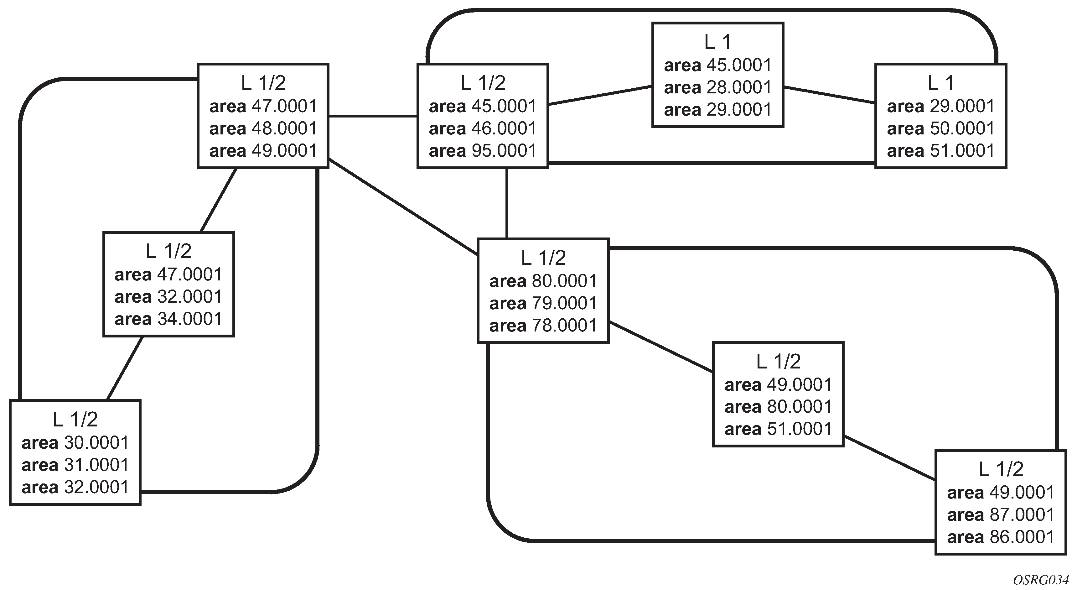
The following figure shows an example of an IS-IS routing domain.

Routing
OSI IS-IS routing uses two-level hierarchical routing. A routing domain can be partitioned into areas. Level 1 routers know the topology in their area, including all routers and end systems in their area but do not know the identity of routers or destinations outside of their area. Level 1 routers forward traffic with destinations outside of their area to a Level 2 router in their area.
Level 2 routers know the Level 2 topology, and know which addresses are reachable by each Level 2 router. Level 2 routers do not need to know the topology within any Level 1 area, except to the extent that a Level 2 router can also be a Level 1 router within a single area. By default, only Level 2 routers can exchange PDUs or routing information directly with external routers located outside the routing domain.
In IS-IS, there are the following types of routers:
Level 1 intermediate systems
Routing is performed based on the area ID portion of the ISO address called the network entity title (NET). Level 1 systems route within an area. They recognize, based on the destination address, whether the destination is within the area. If so, they route toward the destination. If not, they route to the nearest Level 2 router.
Level 2 intermediate systems
Routing is performed based on the area address. They route toward other areas, disregarding other area internal structure. A Level 2 intermediate system can also be configured as a Level 1 intermediate system in the same area.
The Level 1 router area address portion is manually configured (see ISO network addressing). A Level 1 router will not become a neighbor with a node that does not have a common area address. However, if a Level 1 router has area addresses A, B, and C, and a neighbor has area addresses B and D, then the Level 1 router will accept the other node as a neighbor, as address B is common to both routers. Level 2 adjacencies are formed with other Level 2 nodes whose area addresses do not overlap. If the area addresses do not overlap, the link is considered by both routers to be Level 2 only and only Level 2 LSPDUs flow on the link.
Within an area, Level 1 routers exchange LSPs which identify the IP addresses reachable by each router. Specifically, zero or more IP address, subnet mask, and metric combinations can be included in each LSP. Each Level 1 router is manually configured with the IP address, subnet mask, and metric combinations, which are reachable on each interface. A Level 1 router routes as follows:
If a specified destination address matches an IP address, subnet mask, or metric reachable within the area, the PDU is routed via Level 1 routing.
If a specified destination address does not match any IP address, subnet mask, or metric combinations listed as reachable within the area, the PDU is routed toward the nearest Level 2 router.
Level 2 routers include in their LSPs, a complete list of IP address, subnet mask, and metrics specifying all the IP addresses which reachable in their area. This information can be obtained from a combination of the Level 1 LSPs (by Level 1 routers in the same area). Level 2 routers can also report external reachable information, corresponding to addresses reachable by routers in other routing domains or autonomous systems.
IS-IS frequently used terms
area
An area is a routing sub-domain which maintains detailed routing information about its own internal composition, and also maintains routing information which allows it to reach other routing sub-domains. Areas correspond to the Level 1 sub-domain.
end system
End systems send NPDUs to other systems and receive NPDUs from other systems, but do not relay NPDUs. This International Standard does not specify any additional end system functions beyond those supplied by ISO 8473 and ISO 9542.
neighbor
A neighbor is an adjacent system reachable by traversing a single sub-network by a PDU.
adjacency
An adjacency is a portion of the local routing information which pertains to the reachability of a single neighboring end or intermediate system over a single circuit. Adjacencies are used as input to the decision process to form paths through the routing domain. A separate adjacency is created for each neighbor on a circuit and for each level of routing (Level 1 and Level 2) on a broadcast circuit.
circuit
The subset of the local routing information base pertinent to a single local Subnetwork Point of Attachments (SNPAs).
link
The communication path between two neighbors. A link is up when communication is possible between the two SNPAs.
designated IS
The intermediate system on a LAN which is designated to perform additional duties. In particular, the designated IS generates link-state PDUs on behalf of the LAN, treating the LAN as a pseudonode.
pseudonode
Where a broadcast sub-network has n connected intermediate systems, the broadcast sub-network is considered to be a pseudonode. The pseudonode has links to each of the n intermediate systems and each of the ISs has a single link to the pseudonode (instead of n-1 links to each of the other intermediate systems). Link-state PDUs are generated on behalf of the pseudonode by the designated IS.
broadcast sub-network
A multi-access subnetwork that supports the capability of addressing a group of attached systems with a single PDU.
general topology sub-network
A topology that is modeled as a set of point-to-point links, each of which connects two systems. There are several generic types of general topology subnetworks, multipoint links, permanent point-to-point links, dynamic and static point-to-point links.
routing sub-domain
A routing sub-domain consists of a set of intermediate systems and end systems located within the same routing domain.
Level 2 sub-domain
Level 2 sub-domain is the set of all Level 2 intermediate systems in a routing domain.
ISO network addressing
IS-IS uses ISO network addresses. Each address identifies a point of connection to the network, such as a router interface, and is called a Network Service Access Point (NSAP).
An end system can have multiple NSAP addresses, in which case the addresses differ only by the last byte (called the n-selector). Each NSAP represents a service that is available at that node. In addition to having multiple services, a single node can belong to multiple areas.
Each network entity has a special network address called a Network Entity Title (NET). Structurally, an NET is identical to an NSAP address but has an n-selector of 00. Most end systems have one NET. Intermediate systems can have up to three area IDs (area addresses).
NSAP addresses are divided into three parts. Only the area ID portion is configurable.
area ID
A variable length field between 1 and 13 bytes long. This includes the Authority and Format Identifier (AFI) as the most significant byte and the area ID.
system ID
A six-byte system identification. This value is not configurable. The system ID is derived from the system or router ID.
selector ID
A one-byte selector identification that must contain zeros when configuring a NET. This value is not configurable. The selector ID is always 00.
Of the total 20 bytes comprising the NET, only the first 13 bytes, the area ID portion, can be manually configured. As few as one byte can be entered or, at most, 13 bytes. If less than 13 bytes are entered, the rest is padded with zeros.
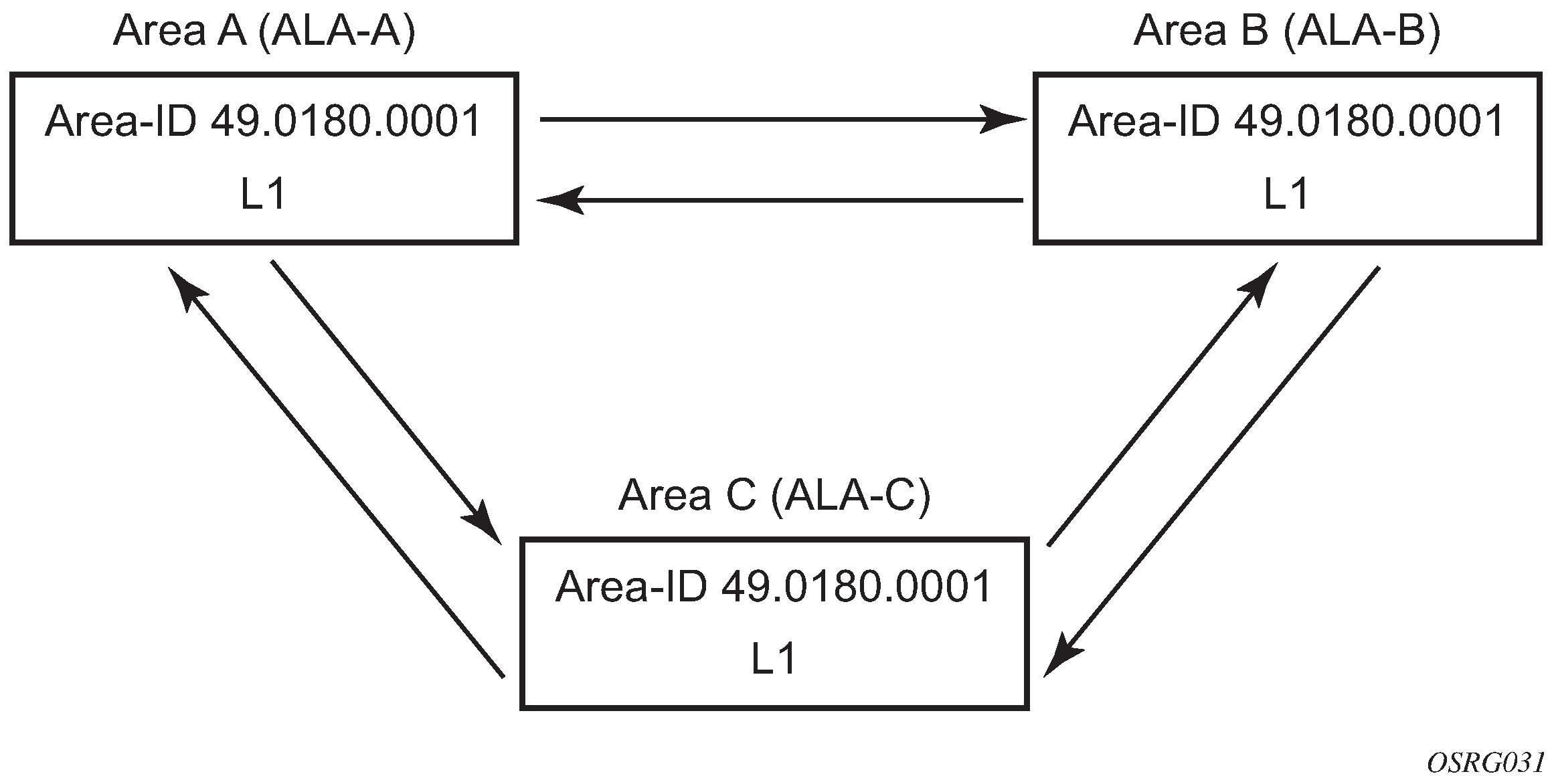
Routers with common area addresses form Level 1 adjacencies. Routers with no common NET addresses form Level 2 adjacencies, if they are capable (see the following figure).
IS-IS PDU configuration
The following PDUs are used by IS-IS to exchange protocol information:
IS-IS hello PDU
Routers with IS-IS enabled send hello PDUs to IS-IS-enabled interfaces to discover neighbors and establish adjacencies.
Link-state PDUs
Contain information about the state of adjacencies to neighboring IS-IS systems. LSPs are flooded periodically throughout an area.
Complete sequence number PDUs
In order for all routers to maintain the same information, CSNPs inform other routers that some LSPs can be outdated or missing from their database. CSNPs contain a complete list of all LSPs in the current IS-IS database.
Partial sequence number PDUs (PSNPs)
PSNPs are used to request missing LSPs and acknowledge that an LSP was received.
IS-IS operations
Routers perform IS-IS routing as follows:
Hello PDUs are sent to the IS-IS-enabled interfaces to discover neighbors and establish adjacencies.
IS-IS neighbor relationships are formed if the hello PDUs contain information that meets the criteria for forming an adjacency.
Routers can build a link-state PDU based upon their local interfaces that are configured for IS-IS and prefixes learned from other adjacent routers.
Routers flood LSPs to the adjacent neighbors except the neighbor from which they received the same LSP. The link-state database is constructed from these LSPs.
A Shortest Path Tree (SPT) is calculated by each IS, and from this SPT the routing table is built.
IS-IS route summarization
IS-IS IPv4 route summarization allows users to create aggregate IPv4 addresses that include multiple groups of IPv4 addresses for a specific IS-IS level. IPv4 Routes redistributed from other routing protocols also can be summarized. It is similar to the OSPF area-range command. IS-IS IPv4 route summarization helps to reduce the size of the LSDB and the IPv4 routing table, and it also helps to reduce the chance of route flapping.
IPv4 route summarization supports:
Level 1, Level 1-2, and Level 2
route summarization for the IPv4 routes redistributed from other protocols
metric used to advertise the summary address is the smallest metric of all the more specific IPv4 routes
IS-IS multi-topology for IPv6
IS-IS IPv6 TLVs for IPv6 routing is supported in 7210 SAS. This is considered native IPv6 routing with IS-IS. It has a limitation that IPv4 and IPv6 topologies must be congruent, otherwise traffic may be blackholed. Service providers should ensure that the IPv4 topology and IPv6 topology are the same. With the IS-IS multi-topology service providers can use different topologies for IPv4 and IPv6.
The implementation is compliant with draft-ietf-isis-wg-multi-topology-xx.txt, M-ISIS: Multi Topology (MT) Routing in IS-IS.
The following MT topologies are supported:
MT ID #0 - equivalent to the standard IS-IS topology
MT ID #2 - reserved for IPv6 routing topology
IS-IS administrative tags
IS-IS administrative tags enable a network administrator to configure route tags to tag IS-IS route prefixes. These tags can subsequently be used to control Intermediate System-to-Intermediate System (IS-IS) route redistribution or route leaking.
The IS-IS support for route tags allows the tagging of IP addresses of an interface and use the tag to apply administrative policy with a route map. A network administrator can also tag a summary route and then use a route policy to match the tag and set one or more attributes for the route.
Using these administrative policies allow the operator to control how a router handles the routes it receives from and sends to its IS-IS neighboring routers. Administrative policies are also used to govern the installation of routes in the routing table.
Route tags allow:
policies to redistribute routes received from other protocols in the routing table to IS-IS
policies to redistribute routes between levels in an IS-IS routing hierarchy
policies to summarize routes redistributed into IS-IS or within IS-IS by creating aggregate (summary) addresses
Setting route tags
IS-IS route tags are configurable in the following ways:
setting a route tag for an IS-IS interface
setting a route tag on an IS-IS passive interface
setting a route tag for a route redistributed from another protocol to IS-IS
setting a route tag for a route redistributed from one IS-IS level to another IS-IS level
setting a route tag for an IS-IS default route
setting a route tag for an IS-IS summary address
Using route tags
The IS-IS administrative tags configured on an IS-IS router (or neighbor) do not have an effect until policies are configured to process the specified tag value.
Policies can process route tags that specify ISIS as either the origin or destination protocol, or as both origin and destination protocol.
config>router>policy-options>policy-statement>entry>from
     config>router>policy-options>policy-statement>entry>action tag tag-value
     config>router>policy-options>policy-statement# default-action tag tag-value
Segment routing in Shortest Path Forwarding
This feature is supported only on the 7210 SAS-Mxp, 7210 SAS-R6, 7210 SAS-R12, and 7210 SAS-Sx/S 1/10GE.
Segment routing (SR) adds to IS-IS and OSPF routing protocols the ability to perform shortest path routing and source routing using the concept of abstract segment. A segment can represent a local prefix of a node, a specific adjacency of the node (interface or next-hop), a service context, or a specific path over the network. For each segment, the IGP advertises an identifier referred to as a segment ID (SID).
When SR is used in combination with the MPLS data plane, the SID acts as a standard MPLS label. A router forwarding a packet using SR therefore pushes one or more MPLS labels. This section describes the SR MPLS feature.
Both shortest path routing and traffic engineering applications can leverage SR MPLS, which encodes a segment as an MPLS label. This section describes the shortest path forwarding applications.
When a received IPv4 prefix SID is resolved, the SR module programs the ILM with a swap operation and the LTN with a push operation, both pointing to the primary/LFA NHLFE. An IPv4 SR tunnel to the prefix destination is also added to the TTM and is available for use by L2 and L3 services.
The SR tunnel in the TTM is available in the following contexts:
IPv4 BGP route label
VLL and LDP VPLS
BGP-AD VPLS when the use-provisioned-sdp option is enabled in the binding to the PW template
intra-AS BGP VPRN for VPN-IPv4 and VPN-IPv6 prefixes, both auto-bind and explicit SDP
The remote LFA feature included in SR expands the coverage of the LFA by computing and automatically programming the SR tunnels that are used as backup next-hops. The SR shortcut tunnels terminate on a remote alternate node, which provides loop-free forwarding for packets of the resolved prefixes. When the loopfree-alternate option is enabled in an IS-IS or OSPF instance, SR tunnels are protected with an LFA backup next-hop. If the prefix of a specific SR tunnel is not protected by the base LFA, the remote LFA automatically computes a backup next-hop using an SR tunnel if the remote-lfa option is also enabled in the IGP instance.
The 7210 SAS-Mxp, 7210 SAS-R6, 7210 SAS-R12, and 7210 SAS-Sx/S 1/10GE do not support remote LFA when services use BGP 3107 labeled route tunnels. The push stack depth in this case exceeds the allowed limit.
The EXP-to-profile mapping for SR is defined in the mpls-lsp-exp-profile-map policy.
On the 7210 SAS-Mxp, 7210 SAS-R6, 7210 SAS-R12, and 7210 SAS-Sx/S 1/10GE, Nokia recommends the use of BGP3107 services using SR to advertise the loopback for BGP 3107 labeled routes to the IGP. This prevents a three-label pop on egress LER.
On the 7210 SAS-Mxp, 7210 SAS-R6, 7210 SAS-R12, and 7210 SAS-Sx/S 1/10GE, when using RLFA with services (and without the use of BGP 3107), if the PQ node is the segment termination, the SR OS always uses the PQ node SID and does not use additional SIDs. Therefore, when the 7210 SAS is configured as an eLER, it always requires two labels to pop and terminate the service packet.
On the 7210 SAS-Mxp, 7210 SAS-R6, 7210 SAS-R12, and 7210 SAS-Sx/S 1/10GE, the maximum label push depth is three MPLS labels, and the maximum label pop depth is two MPLS labels (both push and pop exclude the PW hash label).
Segment routing operational procedures
Prefix advertisement and resolution
When segment routing is enabled in the IS-IS or OSPF instance, the router performs the following operations. See Control protocol changes for more information about the TLVs and sub-TLVs for both IS-IS and OSPF protocols:
Advertises the segment routing capability sub-TLV to routers in all areas or levels of this IGP instance. However, only neighbors with which it established an adjacency interprets the SID or label range information and use it for calculating the label to swap to or push for a resolved prefix SID.
Advertises the assigned index for each configured node SID in the new prefix SID sub-TLV with the N-flag (node-SID flag) set. The segment routing module programs the incoming label map (ILM) with a pop operation for each local node SID in the datapath.
Automatically assigns and advertises an adjacency SID label for each formed adjacency over a network IP interface in the new adjacency SID sub-TLV. The following points should be considered:
The adjacency SID is advertised for both numbered and unnumbered network IP interfaces.
The adjacency SID for parallel adjacencies between two IGP neighbors is not supported.
The adjacency SID is not advertised for an IES interface because access interfaces do not support MPLS.
The adjacency SID must be unique for each instance and for each adjacency. Also, ISIS MT=0 can establish an adjacency for the IPv4 address family over the same link, and in such a case a different adjacency SID is assigned to each next-hop. However, the existing IS-IS implementation assigns a single protect-group ID (PG-ID) to the adjacency, and when the state machine of a BFD session tracking the IPv4 next-hop times out, an action is triggered for the prefixes of the IPv4 address family over that adjacency.
The segment routing module programs the ILM with a swap to an implicit null label operation for each advertised adjacency SID.
Resolve received prefixes and, if a prefix SID sub-TLV exists, the segment routing module programs the ILM with a swap operation and an LTN with a push operation, both pointing to the primary/LFA NHLFE. An SR tunnel is also added to the TTM. If a node SID resolves over an IES interface, the datapath is not programmed and a trap is raised. Therefore, only next-hops of an ECMP set corresponding to network IP interfaces are programmed in the datapath; next-hops corresponding to IES interfaces are not programmed. If, however, the user configures the interface as a network on one side and IES on the other side, MPLS packets for the SR tunnel received on the access side are dropped.
LSA filtering causes SIDs not to be sent in one direction, which means that some node SIDs are resolved in parts of the network upstream of the advertisement suppression.
When the user enables segment routing in an IGP instance, the main SPF and LFA SPF are computed normally and the primary next-hop and LFA backup next-hop for a received prefix are added to RTM without the label information advertised in the prefix SID sub-TLV. In all cases, the segment routing tunnel is not added into the RTM.
Error and resource exhaustion handling
When the prefix corresponding to a node SID is being resolved, the following procedures are followed.
Procedure 1: Providing support of multiple topologies for the same destination prefix
The 7210 SAS supports assigning different prefix-SID indexes and labels to the same prefix in different IGP instances. While other routers that receive these prefix SIDs program a single route into the RTM, based on the winning instance ID as per RTM route type preference, the 7210 SAS adds two tunnels to this destination prefix in the TTM. This provides support for multiple topologies for the same destination prefix.
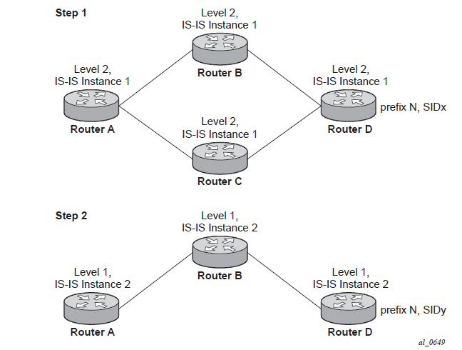
For example, in two different instances (L2, IS-IS instance 1 and L1, IS-IS instance 2 — see the following figure), Router D has the same prefix destination with different SIDs (SIDx and SIDy).
Assume the following route type preference in the RTM and tunnel type preference in the TTM are configured:
ROUTE_PREF_ISIS_L1_INTER (RTM) 15
ROUTE_PREF_ISIS_L2_INTER (RTM) 18
ROUTE_PREF_ISIS_TTM 11
The TTM tunnel type preference is not used by the SR module. It is put in the TTM and is used by other applications, such as VPRN auto-bind, to select a TTM tunnel.
Router A performs the following resolution within the single IS-IS instance 1, level 2. All metrics are the same and ECMP = 2.
For prefix N, the RTM entry is:
prefix N
nhop1 = B
nhop2 = C
preference 18
For prefix N, the SR tunnel TTM entry is:
tunnel-id 1: prefix N-SIDx
nhop1 = B
nhop2 = C
tunl-pref 11 (tunl-pref 10 for OSPF)
Add IS-IS instance 2 (level 1) in the same setup, but in routers A, B, and C only.
For prefix N, the TTM entry is:
prefix N
nhop1 = B
preference 15
RTM prefers the L1 route over the L2 route
For prefix N, there are two SR tunnel entries in the TTM:
SR entry for L2:
tunnel-id 1: prefix N-SIDx
nhop1 = B
nhop2= C
tunl-pref 11 (tunl-pref 10 for OSPF)
SR entry for L1:
tunnel-id 2: prefix N-SIDy
Procedure 2: Resolving received SID indexes or labels to different routes of the same prefix within the same IGP instance
Two variations of this procedure can occur:
When the system does not allow assigning the same SID index or label to different routes of the same prefix within the same IGP instance, it resolves only one of them if they are received from another SR implementation and they are based on the RTM active route selection.
When the system does not allow assigning different SID indexes or labels to different routes of the same prefix within the same IGP instance, it resolves only one of them if they are received from another SR implementation and they are based on the RTM active route selection.
The selected SID is used for ECMP resolution to all neighbors. If the route is inter-area and the conflicting SIDs are advertised by different ABRs, ECMP toward all ABRs uses the selected SID.
Note:The 7210 SAS-Mxp supports only LSR ECMP. It does not support LER ECMP.
Procedure 3: Checking for SID error before programming ILM and NHLFE
If any of the following conditions are true, the router logs a trap and generates a syslog error message, and it does not program the ILM and NHLFE for the prefix SID:
The received prefix SID index falls outside the locally configured SID range.
One or more resolved ECMP next-hops for a received prefix SID did not advertise SR capability sub-TLV.
The received prefix SID index falls outside the advertised SID range of one or more resolved ECMP next-hops.
Procedure 4: Programming ILM/NHLFE for duplicate prefix-SID indexes/labels for different prefixes
Two variations of this procedure can occur.
For received duplicate prefix-SID indexes or labels for different prefixes within the same IGP instance, the router does the following:
programs ILM/NHLFE for the first prefix
logs a trap and a syslog error message
does not program the subsequent prefix in the datapath
For received duplicate prefix-SID indexes for different prefixes across IGP instances, there are two options:
In the global SID index range mode of operation, the resulting ILM label values are the same across the IGP instances. The router does the following:
programs ILM/NHLFE for the prefix of the winning IGP instance based on the RTM route type preference
logs a trap and a syslog error message
does not program the subsequent prefix SIDs in the datapath
In the per-instance SID index range mode of operation, the resulting ILM label will have different values across the IGP instances. The router programs ILM/NHLFE for each prefix as expected.
Procedure 5: Programming ILM/NHLFE for the same prefix across IGP instances
In the global SID index range mode of operation, the resulting ILM label values are the same across the IGP instances. The router programs ILM/NHLFE for the prefix of the winning IGP instance based on the RTM route type preference. The router logs a trap and a syslog error message, and does not program the other prefix SIDs in datapath.
In the per-instance SID index range mode of operation, the resulting ILM label has different values across the IGP instances. The router programs ILM/NHLFE for each prefix as expected.
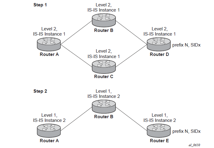
The following figure shows an IS-IS example of the behavior in the case of a global SID index range.
Assume that the following route type preference in the RTM and tunnel type preference in the TTM are configured:
ROUTE_PREF_ISIS_L1_INTER (RTM) 15
ROUTE_PREF_ISIS_L2_INTER (RTM) 18
ROUTE_PREF_ISIS_TTM 11
The TTM tunnel type preference is not used by the SR module. It is put in the TTM and is used by other applications, such a VPRN auto-bind, to select a TTM tunnel.
Router A performs the following resolution within the single IS-IS instance 1, level 2. All metrics are the same, and ECMP = 2.
For prefix N, the RTM entry is the following:
prefix N
nhop1 = B
nhop2 = C
preference 18
For prefix N, the SR tunnel TTM entry is the following:
tunnel-id 1: prefix N-SIDx
nhop1 = B
nhop2 = C
tunl-pref 11 (tunl-pref 10 for OSPF)
Add IS-IS instance 2 (level 1) in the same setup, but in routers A, B, and E only.
For prefix N, the RTM entry is the following:
prefix N
nhop1 = B
preference 15
RTM prefers the L1 route over the L2 route.
For prefix N, there is one SR tunnel entry for L2 in the TTM:
tunnel-id 1: prefix N-SIDx
nhop1 = B
nhop2 = C
tunl-pref 11 (tunl-pref 10 for OSPF)
Procedure 6: Handling ILM resource exhaustion while assigning an SID index/label
If the system exhausts an ILM resource while assigning an SID index or label to a local loopback interface, index allocation fails and an error is returned in the CLI. In addition, the router logs a trap and generates a syslog error message.
Procedure 7: Handling ILM/NHLFE/other IOM or CPM resource exhaustion while resolving or programming an SID index/label
If the system exhausts an ILM, NHLFE, or any other IOM or CPM resource while resolving and programming a received prefix SID or programming a local adjacency SID, the following occurs.
The IGP instance goes into overload and a trap and syslog error message are generated.
The segment routing module deletes the tunnel.
The user must manually clear the IGP overload condition after freeing resources. After the IGP is brought back up, it attempts to program at the next SPF all tunnels which previously failed the programming operation.
Segment routing tunnel management
The segment routing module adds to the TTM a shortest path SR tunnel entry for each resolved remote node SID prefix and programs the datapath with the corresponding LTN with the push operation pointing to the primary and LFA backup NHLFEs. The LFA backup next-hop for a prefix that was advertised with a node SID is computed only if the loopfree-alternate option is enabled in the IS-IS or OSPF instance. The resulting SR tunnel that is populated in the TTM is automatically protected with FRR when an LFA backup next-hop exists for the prefix of the node SID.
With ECMP, a maximum number of primary next-hops (NHLFEs) are programmed for the same tunnel destination per IGP instance. ECMP and LFA next-hops are mutually exclusive as per the existing implementation.
The 7210 SAS-Mxp, 7210 SAS-R6, 7210 SAS-R12, and 7210 SAS-Sx/S 1/10GE support only LSR ECMP; LER ECMP is not supported on these platforms.
The default preference for shortest path SR tunnels in the TTM is set lower than LDP tunnels but higher than BGP tunnels to allow controlled migration of customers without disrupting their current deployment when they enable segment routing. The following list presents the default preference of the various tunnel types. This includes the preference of both SR tunnels based on shortest path (referred to as SR-ISIS and SR-OSPF).
The global default TTM preference for the tunnel types is as follows:
ROUTE_PREF_RSVP 7
ROUTE_PREF_SR_TE 8
ROUTE_PREF_LDP 9
ROUTE_PREF_OSPF_TTM 10
ROUTE_PREF_ISIS_TTM 11
ROUTE_PREF_BGP_TTM 12
ROUTE_PREF_GRE 255
The default value for SR-ISIS or SR-OSPF is the same regardless of whether one or more IS-IS or OSPF instances are programming a tunnel for the same prefix. The selection of an SR tunnel in this case is based on the lowest IGP instance.
The TTM preference is used in the case of VPRN auto-bind or BGP transport tunnels when the tunnel binding commands are configured to the any value, which parses the TTM for tunnels in the protocol preference order. The user can choose to either use the global TTM preference or list explicitly the tunnel types to be used. When the tunnel types are listed, the TTM preference is still used to select one type over the other. In both cases, a fallback to the next preferred tunnel type is performed if the selected one fails. Also, a reversion to a preferred tunnel type is performed as soon as one is available. See BGP label route resolution using segment routing tunnels and Service packet forwarding with segment routing for the detailed service and shortcut binding CLI.
For SR-ISIS and SR-OSPF, the user can configure the preference of each IGP instance in addition to the preceding default values.
configure>router>isis>segment-routing>tunnel-table-pref preference <1..255>
    configure>router>ospf>segment-routing>tunnel-table-pref preference <1..255>
SR tunnels in the TTM are available to BPG routes, VPRN auto-bind and explicit SDP binding, and L2 services with PW template auto-bind and explicit SDP binding.
Local adjacency SIDs are not programmed into the TTM, but the remote adjacency SIDs can be used together with a node SID in a tunnel configuration in a directed LFA.
Tunnel MTU determination
The MTU of an SR tunnel populated into the TTM is determined the same way as it is for an IGP tunnel; for example, LDP LSP, based on the outgoing interface MTU minus the label stack size. Segment routing, however, supports remote LFA, which programs an LFA backup next-hop adding another label to the tunnel for a total of two labels.
The user must configure the MTU of all SR tunnels within each IGP instance:
configure>router>isis>segment-routing>tunnel-mtu bytes
    configure>router>ospf>segment-routing>tunnel-mtu bytes
There is no default value for this new command. If the user does not configure an SR tunnel MTU, the MTU is fully determined by IGP.
The MTU of the SR tunnel, in bytes, is determined as follows:
Where:
Cfg_SR_MTU is the MTU configured by the user for all SR tunnels within a specific IGP instance using the preceding commands. If no value was configured by the user, the SR tunnel MTU is determined by the IGP interface calculation.
IGP_Tunnel_MTU is the minimum of the IS-IS or OSPF interface MTU among all the ECMP paths or among the primary and LFA backup paths of this SR tunnel.
frr-overhead is set to 1 if segment-routing and remote-lfa options are enabled in the IGP instance. Otherwise, it is set to 0.
The SR tunnel MTU is dynamically updated whenever any of the preceding parameters changes. This includes when the set of the tunnel next-hops changes, or the user changes the configured SR MTU or interface MTU value.
For the purpose of fragmentation of IP packets forwarded in GRT or in a VPRN over an SR shortest path tunnel, the IOM always deducts the worst case MTU (5 labels or 6 labels if the hash label feature is enabled) from the outgoing interface MTU for the decision to fragment the packet or not. In this case, the preceding formula is not used.
Remote LFA with segment routing
The remote LFA next-hop calculation by the IGP LFA SPF is enabled by appending the remote-lfa option to the loopfree-alternate command:
configure>router>isis>loopfree-alternate remote-lfa
    configure>router>ospf>loopfree-alternate remote-lfa
The SPF calculates the remote LFA after the regular LFA next-hop calculation when the following conditions are met:
The remote-lfa option is enabled in an IGP instance.
The LFA next-hop calculation did not result in protection for one or more prefixes resolved to a specific interface.
Remote LFA extends the loop-free alternate fast reroute (LFA FRR) protection coverage to any topology by automatically computing and establishing or tearing down shortcut tunnels (repair tunnels) to a remote LFA node that puts the packets back on the shortest path without looping them back to the node that forwarded them over the repair tunnel. A repair tunnel can be an RSVP LSP, an LDP-in-LDP tunnel, or an SR tunnel. This feature is restricted to using an SR repair tunnel to the remote LFA node.
The remote LFA feature can only use an SR repair tunnel to the remote LFA node.
The remote LFA algorithm for link protection is described in RFC 7490, Remote Loop-Free Alternate (LFA) Fast Reroute (FRR). Unlike the regular LFA calculation, which is calculated per prefix, the LFA algorithm for link protection is a per-link LFA SPF calculation. It provides protection for all destination prefixes that share the protected link by using the neighbor on the other side of the protected link as a proxy for all destinations. The following figure shows an example of a remote LFA topology.

When the LFA SPF in node C computes the per-prefix LFA next-hop, prefixes that use link C to B as the primary next-hop have no LFA next-hop because of the ring topology. If node C uses node link C to D as a back-up next-hop, node D loops a packet back to node C. The remote LFA then runs the ‟PQ Algorithm” as described in RFC 7490.
Computes the extended P space of node C for link C to B. The extended P space is the set of nodes reachable from node C without any path transiting the protected link (C to B). The computation yields nodes D, E, and F.
The extended P space of node C is determined by running SPF on behalf of each of the neighbors of C; the same computation is used for the regular LFA.
Note:According to the P space concept initially introduced in RFC 7490, node F would be excluded from the P space because, from the node C perspective, a few node C has a couple of ECMP paths would already exist in node C, including a path going through link C to B. However, because the remote LFA next-hop is activated when link C-B fails, this rule can be relaxed to include node F, which then yields the extended P space.
You can limit the search for candidate P nodes to reduce the number of SPF calculations in topologies where many eligible P nodes may exist. Use the following CLI commands to configure the maximum IGP cost from node C for a P node to be an eligible candidate:
configure>router>isis>loopfree-alternate remote-lfa max-pq-cost value
configure>router>ospf>loopfree-alternate remote-lfa max-pq-cost value
Compute the Q space of node B for link C-B. The Q space is the set of nodes from which the destination proxy (node B) can be reached without a path transiting the protected link (link C-B).
The Q space calculation is a reverse SPF on node B. A reverse SPF is run on behalf of each neighbor of C to protect all destinations that resolve over the link to the neighbor. This yields nodes F and A in the example shown in Example topology remote LFA algorithm.
You can limit the search for candidate Q nodes to reduce the number of SPF calculations in topologies where many eligible Q nodes may exist. Use the CLI commands described in step1 to configure the maximum IGP cost from node C for a Q node to be an eligible candidate.
Select the best alternate node, which is the intersection of extended P and Q spaces. In the Example topology remote LFA algorithm example, the best alternate node (PQ node) is node F. From node F onwards, traffic follows the IGP shortest path.
If many PQ nodes exist, the lowest IGP cost from node C is used to narrow the selection; if more than one PQ node remains, the node with the lowest router ID is selected.
The following figure shows label stack encoding for a packet that is forwarded over the remote LFA next-hop.

The label corresponding to the node SID of the PQ node is pushed on top of the original label of the SID of the resolved destination prefix. If node C has resolved multiple node SIDs corresponding to different prefixes of the selected PQ node, it pushes the lowest node SID label on the packet when forwarded over the remote LFA backup next-hop.
If the PQ node is also the advertising router for the resolved prefix, the label stack is compressed in the following cases depending on the IGP:
In IS-IS, the label stack is always reduced to a single label, which is the label of the resolved prefix owned by the PQ node.
In OSPF, the label stack is reduced to the single label of the resolved prefix when the PQ node advertises a single node SID in this OSPF instance. If the PQ node advertises a node SID for multiple of its loopback interfaces within the same OSPF instance, the label stack is reduced to a single label only in the case where the SID of the resolved prefix is the lowest SID value.
The following rules and limitations apply to the remote LFA implementation:
LFA policy is supported for IP next-hops only. It is not supported with tunnel next-hops when IGP shortcuts are used for LFA backup. Remote LFA is also a tunnel next-hop and a user-configured LFA policy is not applied in the selection of a remote LFA backup next-hop when multiple candidates are available.
As a result, if an LFA policy is applied and does not find an LFA IP next-hop for a set of prefixes, the remote LFA SPF searches for a remote LFA next-hop for the same prefixes. The selected remote LFA next-hops, if found, may not satisfy the LFA policy constraints.
If the loopfree-alternate-exclude CLI command (IS-IS or OSPF context of the interface) is used to exclude a network IP interface from being used as an LFA next-hop, the interface is also excluded from being used as the outgoing interface for a remote LFA tunnel next-hop.
As with the regular LFA algorithm, the remote LFA algorithm computes a backup next-hop to the ABR advertising an inter-area prefix and not to the destination prefix.
Datapath support
A packet received with a label matching either a node SID or an adjacency SID is forwarded according to the ILM type and operation, as described in the following table.
Label type |
Operation |
|---|---|
Top label is a local node SID |
The label is popped and the packet is further processed. If the SID label of the popped node is at the bottom of the stack label, the IP packet is looked up and forwarded in the appropriate FIB. |
Top or next label is a remote node SID |
The label is swapped to the calculated label value for the next-hop and forwarded according to the primary or backup NHLFE. With ECMP, a number of primary next-hops (NHLFEs) are programmed for the same destination prefix and for each IGP instance. ECMP and LFA next-hops are mutually exclusive. |
Top or next label is an adjacency SID |
The label is popped and the packet is forwarded out of the interface to the next-hop associated with this adjacency SID label. In effect, the datapath operation is modeled like a swap to an implicit-null label instead of a pop. |
Next label is BGP 3107 label |
The packet is further processed according to the ILM operation.
|
Next label is a service label |
The packet is looked up and forwarded in the Layer 2 or VPRN FIB. |
A router forwarding an IP or service packet over an SR tunnel pushes a maximum of three transport labels with a remote LFA next-hop.
Four label push is not supported on the 7210 SAS-Mxp.
Hash label
When the hash-label option is enabled in a service context, the hash label is always inserted at the bottom of the stack.
On the 7210 SAS-Mxp, hash labels are supported only with specific services. See the 7210 SAS-Mxp, S, Sx, T Services Guide for more information about the services supported with hash label.
Control protocol changes
This section describes the IS-IS control protocol changes and OSPF control protocol changes.
IS-IS control protocol changes
The following TLVs/sub-TLVs are defined in draft-ietf-isis-segment-routing-extensions and are supported in the implementation of SR in IS-IS:
prefix SID sub-TLV
adjacency SID sub-TLV
SID/Label Binding TLV
SR-Capabilities sub-TLV
SR-Algorithm sub-TLV
This section describes the behaviors and limitations of using SR TLVs and sub-TLVs with IS-IS.
The 7210 SAS supports advertising the IS router capability TLV (RFC 4971) only for topology MT=0. As a result, the SR-Capabilities sub-TLV can be advertised only in MT=0, which restricts the segment routing feature to MT=0.
Similarly, if prefix SID sub-TLVs for the same prefix are received in different MT numbers of the same IS-IS instance, only the one in MT=0 is resolved. When the prefix SID index is also duplicated, an error is logged and a trap is generated, as described in Error and resource exhaustion handling.
The I and V flags are both set to 1 when originating the SR-Capabilities sub-TLV to indicate support for processing SR MPLS encapsulated IPv4 and IPv6 packets on its network interfaces. These flags are not checked when the sub-TLV is received. Only the SRGB range is processed.
The algorithm field is set to 0, meaning it uses the SPF algorithm based on link metric, when the SR-Algorithm sub-TLV is originated but the field is not checked when the sub-TLV is received.
Only an IPv4 prefix and adjacency SID sub-TLVs can be originated within MT=0. An IPv6 prefix and adjacency SID sub-TLVs can, however, be received and ignored. Use the show command to display (dump) the octets of the received but unsupported sub-TLVs.
The 7210 SAS originates a single prefix SID sub-TLV per IS-IS IP reachability TLV and processes the first prefix SID sub-TLV only if multiple prefix SID sub-TLVs are received within the same IS-IS IP reachability TLV.
The 7210 SAS encodes the 32-bit index in the prefix SID sub-TLV. The 24-bit label is not supported.
The 7210 SAS originates a prefix SID sub-TLV with the following flag encoding and processing rules:
The R-flag is set if the prefix SID sub-TLV, along with its corresponding IP reachability TLV, is propagated between levels.
The N-flag is always set because the system supports a prefix SID of type node SID only.
The P-flag (no-PHP flag) is always set, meaning that the label for the prefix SID is pushed by the penultimate hop popping (PHP) router when forwarding to this router. The 7210 SAS PHP router processes a received prefix SID with the P-flag set to zero and uses implicit-null for the outgoing label toward the router that advertised it, as long as the P-flag is also set to 1.
The E-flag (Explicit-Null flag) is always set to zero. The 7210 SAS PHP router, however, processes a received prefix SID with the E-flag set to 1 and, when the P-flag is also set to 1, it pushes explicit-null for the outgoing label toward the router that advertised it.
The V-flag is always set to 0 to indicate an index value for the SID.
The L-flag is always set to 0 to indicate that the SID index value is not locally significant.
The algorithm field is always set to zero to indicate that the SPF algorithm is based on the link metric and is not checked on a received prefix SID sub-TLV.
The system resolves a prefix SID sub-TLV received without the N-flag set but with the prefix length equal to 32. A trap, however, is raised by IS-IS.
The system does not resolve a prefix SID sub-TLV received with the N flag set and a prefix length different than 32. A trap is raised by IS-IS.
The system resolves a prefix SID received within an IP reachability TLV based on the following route preference:
SID received via level 1 in a prefix SID sub-TLV part of IP reachability TLV
SID received via level 2 in a prefix SID sub-TLV part of IP reachability TLV
A prefix received in an IP reachability TLV is propagated, along with the prefix SID sub-TLV, by default from level 1 to level 2 by a level 1/2 router. A router in level 2 sets up an SR tunnel to the level 1 router via the level 1/2 router, which acts as an LSR.
A prefix received in an IP reachability TLV is not propagated, along with the prefix SID sub-TLV, by default from level 2 to level 1 by a level 1/2 router. If the user adds a policy to propagate the received prefix, a router in level 1sets up an SR tunnel to the level 2 router via the level 1/2 router, which acts as an LSR.
If a prefix is summarized by an ABR, the prefix SID sub-TLV is not propagated with the summarized route between levels. To propagate the node SID for a /32 prefix, route summarization must be disabled.
The 7210 SAS propagates the prefix SID sub-TLV when exporting the prefix to another IS-IS instance; however, it does not propagate it if the prefix is exported from a different protocol. When the corresponding prefix is redistributed from another protocol, such as OSPF, the prefix SID is removed.
The 7210 SAS originates an adjacency SID sub-TLV with the flags encoded as follows:
The F-flag is set to 0 to indicate an IPv4 family and 1 to indicate an IPv6 family for the adjacency encapsulation.
The B-Flag is set to 0 and is not processed on receipt.
The V-flag is always set to 1.
The L-flag is always set to 1.
The S-flag is set to 0 because assigning an adjacency SID to parallel links between neighbors is not supported. A received adjacency SID with the S-flag set is not processed.
The weight octet is not supported and is set to all zeros.
The system does not originate the SID/Label Binding TLV, but can process it if received. The following rules and limitations should be considered:
Only the mapping server prefix-SID sub-TLV within the TLV is processed, and the ILMs are installed if the prefixes in the provided range are resolved.
The range and FEC prefix fields are processed. Each FEC prefix is resolved in the same manner as the prefix SID sub-TLV. In other words, an IP reachability TLV must be received for the exact matching prefix.
If the same prefix is advertised with both a prefix SID sub-TLV and a mapping server prefix-SID sub-TLV, the system uses the following route preference for resolution:
SID received via level 1 in a prefix SID sub-TLV part of the IP reachability TLV
SID received via level 2 in a prefix SID sub-TLV part of the IP reachability TLV
SID received via level 1 in a mapping server prefix-SID sub-TLV
SID received via level 2 in a mapping server prefix-SID sub-TLV
No route leaking of the entire TLV is performed between levels. However, a level 1/2 router will propagate the prefix-SID sub-TLV from the SID/Label Binding TLV (received from a mapping server) into the IP reachability TLV if the latter is propagated between levels.
The mapping server that advertises the SID/Label Binding TLV does not need to be in the shortest path for the FEC prefix.
If the same FEC prefix is advertised in multiple binding TLVs by different routers, the SID in the binding TLV of the first router that is reachable is used. If that router becomes unreachable, the next reachable router is used.
No check is performed of whether the content of the binding TLVs from different mapping servers is consistent.
Other sub-TLV, for example, the SID/Label Sub-TLV, ERO metric, and unnumbered interface ID ERO, are ignored. However, the user can run the IGP show command to get a list of the octets of the received but unsupported sub-TLVs.
OSPF control protocol changes
The following TLVs/sub-TLVs are defined in draft-ietf-ospf-segment-routing-extensions-04 and are required for the implementation of segment routing in OSPF:
prefix SID sub-TLV part of the OSPFv2 Extended Prefix TLV
prefix SID sub-TLVpart of the OSPFv2 Extended Prefix Range TLV
adjacency SID sub-TLV part of the OSPFv2 Extended Link TLV
SID/Label Range Capability TLV
SR-Algorithm Capability TLV
This section describes the behaviors and limitations of the OSPF support of segment routing TLVs and sub-TLVs.
The 7210 SAS originates a single prefix SID sub-TLV for each OSPFv2 Extended Prefix TLV and processes the first one only if multiple prefix SID sub-TLVs are received within the same OSPFv2 Extended Prefix TLV.
The 7210 SAS encodes the 32-bit index in the prefix SID sub-TLV. The 24-bit label or variable IPv6 SID is not supported.
The 7210 SAS originates a prefix SID sub-TLV with the following flag encoding:
The NP-flag is always set, meaning that the label for the prefix SID is pushed by the PHP router when forwarding to this router. 7210 SAS PHP routers process a received prefix SID with the NP-flag set to zero and use implicit-null for the outgoing label toward the router that advertised it.
The M-flag is always unset because the 7210 SAS does not support originating a mapping server prefix-SID sub-TLV.
The E-flag is always set to 0. The 7210 SAS PHP routers properly process a received prefix SID with the E-flag set to 1, and when the NP-flag is also set to 1, they push explicit-null for the outgoing label toward the router that advertised it.
The V-flag is always set to 0 to indicate an index value for the SID.
The L-flag is always set to 0 to indicate that the SID index value is not locally significant.
The algorithm field is always set to 0 to indicate the SPF algorithm is based on the link metric and is not checked on a received prefix SID sub-TLV.
The system resolves a prefix SID received within an extended prefix TLV based on the following route preference:
SID received via an intra-area route in a prefix SID sub-TLV part of Extended Prefix TLV
SID received via an inter-area route in a prefix SID sub-TLV part of Extended Prefix TLV
The 7210 SAS originates an adjacency SID sub-TLV with the following encoding of the flags.
The F-flag is not set to indicate the adjacency SID refers to an adjacency with outgoing IPv4 encapsulation.
The B-flag is set to 0 and is not processed on receipt.
The V-flag is always set.
The L-flag is always set.
The S-flag is not supported.
The weight octet is not supported and is set to all zeros.
The 7210 SAS does not originate the OSPFv2 Extended Prefix Range TLV but can process it if received. The following rules and limitations should be considered:
Only the prefix SID sub-TLV within the TLV is processed, and the ILMs are installed if the prefixes are resolved.
The range and address prefix fields are processed. Each prefix is resolved separately.
If the same prefix is advertised with both a prefix SID sub-TLV in an IP reachability TLV and a mapping server Prefix-SID sub-TLV, the resolution follows the following route preference:
the SID received via an intra-area route in a prefix SID sub-TLV part of Extended Prefix TLV
the SID received via an inter-area route in a prefix SID sub-TLV part of Extended Prefix TLV
the SID received via an intra-area route in a prefix SID sub-TLV part of an OSPFv2 Extended Range Prefix TLV
the SID received via an inter-area route in a prefix SID sub-TLV part of an OSPFv2 Extended Range Prefix TLV
No route leaking of any part of the TLV is allowed between areas. In addition, an ABR does not propagate the prefix-SID sub-TLV from the Extended Prefix Range TLV (received from a mapping server) into an Extended Prefix TLV if the latter is propagated between areas.
The mapping server that advertised the OSPFv2 extended prefix range TLV does not need to be in the shortest path for the FEC prefix.
If the same FEC prefix is advertised in multiple OSPFv2 extended prefix range TLVs by different routers, the SID in the TLV of the first router that is reachable is used. If that router becomes unreachable, the next reachable one is used.
No check is performed to determine whether the contents of the OSPFv2 Extended Prefix Range TLVs received from different mapping servers are consistent.
Any other sub-TLV (for example, the ERO metric and unnumbered interface ID ERO) is ignored, but the user can get a list of the octets of the received but unsupported sub-TLVs using the existing IGP show command.
The 7210 SAS supports the propagation on ABR of an external prefix LSA into other areas with the route type set to 3 as per draft-ietf-ospf-segment-routing-extensions-04.
The 7210 SAS supports the propagation on ABR of external prefix LSAs with route type 7 from the NSSA area into other areas with the route type set to 5, as described in draft-ietf-ospf-segment-routing-extensions-04. The system does not support the propagation of the prefix SID sub-TLV between OSPF instances.
If an OSPF import policy is configured, the outcome of the policy applies to prefixes resolved in RTM and the corresponding tunnels in TTM. A prefix that is removed by the policy is removed as both a route in the RTM and as an SR tunnel in the TTM.
BGP label route resolution using segment routing tunnels
Configure the following CLI commands to enable the resolution of RFC 3107 BGP label route prefixes using SR tunnels to BGP next-hops in the TTM.
The 7210 SAS-Mxp, 7210 SAS-R6, 7210 SAS-R12, and 7210 SAS-Sx/S 1/10GE do not support RFLA with BGP 3107 labeled tunnel routes.
configure>router>bgp>next-hop-resolution
        labeled-route-transport-tunnel
            [no] family family
                resolution {any | disabled | filter}
                resolution-filter
                    [no] sr-isis
                    [no] sr-ospf
                exit
            exit
        exit
    exit
If the resolution option is explicitly set to disabled, the default binding to LDP tunnel is used. If resolution option is set to any, a supported tunnel type from the BGP label route context is selected following the TTM preference.
The following tunnel types are supported in a BGP label route context and are listed in order of preference:
RSVP
LDP
segment routing
When sr-isis or sr-ospf is configured using the resolution-filter option, a tunnel to the BGP next-hop is selected in the TTM from the lowest numbered IS-IS or OSPF instance.
See the BGP chapter for information about BGP label route resolution using SR tunnels.
Service packet forwarding with segment routing
The following SDP subtypes of the MPLS type allow service binding to an SR tunnel programmed in the TTM by OSPF or IS-IS:
config>service>sdp>sr-isis
config>service>sdp>sr-ospf
SDPs of type sr-isis or sr-ospf can be configured with the far-end CLI command. When the sr-isis or sr-ospf command is enabled, a tunnel to the far-end address is selected in the TTM from the lowest preference IS-IS or OSPF instance. If multiple instances have the same lowest preference from the lowest numbered IS-IS or OSPF instance, the SR-ISIS or SR-OSPF tunnel is selected at the time of the binding, using the tunnel selection rules. If a preferred tunnel is subsequently added to the TTM, the SDP does not automatically switch to the new tunnel until the next time the SDP is being re-resolved.
The tunnel-far-end option is not supported. In addition, the mixed-lsp-mode option does not support the sr-isis and sr-ospf tunnel types.
The signaling protocol for the service labels of an SDP using an SR tunnel can be configured to static (off), T-LDP (tldp), or BGP (bgp).
SR tunnels can be configured in a VPRN service with the auto-bind-tunnel command.
VPN-IPv4 and VPN-IPv6 (6VPE) are supported in a VPRN or BGP EVPN service using segment routing transport tunnels with the auto-bind-tunnel command.
See BGP and see the 7210 SAS-Mxp, S, Sx, T Services Guide for more information about the VPRN auto-bind-tunnel CLI command.
The following service contexts are supported with SR tunnels:
VLL and LDP VPLS
BGP-AD VPLS when the use-provisioned-sdp option is enabled in PW template binding
intra-AS BGP VPRN for VPN-IPv4 and VPN-IPv6 prefixes with both auto-bind and explicit SDP
The following service contexts are not supported:
inter-AS VPRN
dynamic MS-PW, PW-switching
BGP-AD VPLS with auto-generation of SDP using an SR tunnel when binding to a PW template
Mirror services
SR tunnels for mirror services are not supported on 7210 SAS platforms.
The user can configure a spoke-SDP bound to an SR tunnel to forward mirrored packets from a mirror source to a remote mirror destination. In the configuration of the mirror destination service at the destination node, the remote-source command must use a spoke-SDP with a VC-ID that matches the VC-ID configured in the mirror destination service at the mirror source node. The far-end option is not supported with an SR tunnel.
Use the following syntax to configure a mirror source node.
config mirror mirror-dest service-id
        no spoke-sdp <sdp-id:vc-id>
        spoke-sdp <sdp-id:vc-id> [create]
            egress
vc-label <egress-vc-label>sdp-id matches an SDP that uses an SR tunnel.
For vc-label, both static and T-LDP egress VC labels are supported.
Use the following syntax to configure a mirror destination node.
configure mirror mirror-dest service-id remote-source
        spoke-sdp <SDP-ID>:<VC-ID> create <-- VC-ID matching that of spoke-sdp configured in mirror destination context at mirror source node.
ingress
                vc-label <ingress-vc-label> <--- optional: both static and t-ldp ingress vc label are supported.
            exit
            no shutdown
        exit
exitThe far-end command in the config>mirror>mirror-dest>remote-source context is not supported with SR tunnels at a mirror destination node; the user must reference a spoke-SDP using a segment routing SDP coming from a mirror source node.
For vc-label, both static and T-LDP ingress VC labels are supported.
IGP-LDP synchronization
The 7210 SAS supports IGP-LDP synchronization on IS-IS routes. See to the 7210 SAS-Mxp, R6, R12, S, Sx, T Router Configuration Guide for more information.
Static route-LDP synchronization is supported on all 7210 SAS platforms as described in this document.
IS-IS import policy on the 7210 SAS-Mxp
IS-IS import policies block routes and prevent them from being installed in the routing table, but do not prevent the prefixes from being propagated in Link State PDUs (LSPs).
Nokia recommends that the user must exercise caution when configuring this feature. Failure to do so may cause unintended connectivity loss (black holes).
The following match conditions are supported for IS-IS import policies:
from level
from prefix-list
from protocol isis [all | instance instance]
from tag
The following actions are supported with IS-IS import policies:
accept (installs the matched prefixes into the routing table)
reject (blocks the matched prefixes from being added to the routing table)
next-policy
Actions that modify the metric value, RTM preference, or route tag value of an accepted IS-IS route may be present in a route policy but are ignored when that policy is applied as an IS-IS import policy.
IS-IS configuration process overview
The following figure shows the process to provision basic IS-IS parameters.

Configuration notes
The following describes IS-IS configuration restrictions:
IS-IS must be enabled on each participating routers.
There are no default network entity titles.
There are no default interfaces.
By default, routers are assigned a Level 1/Level 2 level capability.
Configuring IS-IS with CLI
This section provides information to configure intermediate-system-to-intermediate-system (IS-IS) using the command line interface.
IS-IS configuration overview
Router levels
The router level capability can be configured globally and on a per-interface basis. The interface-level parameters specify the interface routing level. The neighbor capability and parameters define the adjacencies that are established.
IS-IS is not enabled by default. When IS-IS is enabled, the global default level capability is Level 1/2, which enables the router to operate as either a Level 1 and/or a Level 2 router with the associated databases. The router runs separate shortest path first (SPF) calculations for the Level 1 area routing and for the Level 2 multi-area routing to create the IS-IS routing table.
The level value can be modified on both or either of the global and interface levels to be only Level 1-capable, only Level 2-capable or Level 1 and Level 2-capable.
If the default value is not modified on any routers in the area, then the routers try to form both Level 1 and Level 2 adjacencies on all IS-IS interfaces. If the default values are modified to Level 1 or Level 2, then the number of adjacencies formed are limited to that level only.
Area address attributes
The area-id command specifies the area address portion of the NET which is
used to define the IS-IS area to which the router will belong. At least one
area-id command should be configured on each router participating
in IS-IS. A maximum of three area-id commands can be configured per
router.
The area address identifies a point of connection to the network, such as a router interface, and is called a network service access point (NSAP). The routers in an area manage routing tables about destinations within the area. The Network Entity Title (NET) value is used to identify the IS-IS area to which the router belongs.
NSAP addresses are divided into three parts. Only the Area ID portion is configurable.
-
area ID
A variable length field between 1 and 13 bytes long. This includes the Authority and Format Identifier (AFI) as the most significant byte and the area ID.
-
system ID
A six-byte system identification. This value is not configurable. The system ID is derived from the system or router ID.
-
selector ID
A one-byte selector identification that must contain zeros when configuring a NET. This value is not configurable. The selector ID is always 00.
The following example displays ISO addresses in IS-IS address format:
MAC address 00:a5:c7:6b:c4:90 |
49.0011.00a5.c76b.c490.00 |
IP address: 218.112.14.5 |
49.0011.2181.1201.4005.00 |
Interface level capability
The level capability value configured on the interface level is compared to the level capability value configured on the global level to determine the type of adjacencies that can be established. The default level capability for routers and interfaces is Level 1/2.
The following table describes configuration combinations and the potential adjacencies that can be formed.
Global level |
Interface level |
Potential adjacency |
|---|---|---|
L 1/2 |
L 1/2 |
Level 1 and/or Level 2 |
L 1/2 |
L 1 |
Level 1 only |
L 1/2 |
L 2 |
Level 2 only |
L 2 |
L 1/2 |
Level 2 only |
L 2 |
L 2 |
Level 2 only |
L 2 |
L 1 |
none |
L 1 |
L 1/2 |
Level 1 only |
L 1 |
L 2 |
none |
L 1 |
L 1 |
Level 1 only |
Route leaking
The Nokia implementation of IS-IS route leaking is performed in compliance with RFC 2966, Domain-wide Prefix Distribution with Two-Level IS-IS. As previously stated, IS-IS is a routing domain (an autonomous system running IS-IS) which can be divided into Level 1 areas with a Level 2-connected subset (backbone) of the topology that interconnects all of the Level 1 areas. Within each Level 1 area, the routers exchange link state information. Level 2 routers also exchange Level 2 link state information to compute routes between areas.
Routers in a Level 1 area typically only exchange information within the Level 1 area. For IP destinations not found in the prefixes in the Level 1 database, the Level 1 router forwards PDUs to the nearest router that is in both Level 1/Level 2 with the attached bit set in its Level 1 link-state PDU.
There are many reasons to implement domain-wide prefix distribution. The goal of domain-wide prefix distribution is to increase the granularity of the routing information within the domain. The routing mechanisms specified in RFC 1195 are appropriate in many situations and account for excellent scalability properties. However, in specific circumstances, the amount of scalability can be adjusted which can distribute more specific information than described by RFC 1195.
Distributing more prefix information can improve the quality of the resulting routes. A well known property of default routing is that loss of information can occur. This loss of information affects the computation of a route based upon less information which can result in sub-optimal routes.
Basic IS-IS configuration
For IS-IS to operate on routers, IS-IS must be explicitly enabled, and at least one area address and interface must be configured. If IS-IS is enabled but no area address or interface is defined, the protocol is enabled but no routes are exchanged. When at least one area address and interface are configured, then adjacencies can be formed and routes exchanged.
To configure IS-IS, perform the following tasks:
Enable IS-IS (specifying the instance ID of multi-instance IS-IS is to be enabled).
If necessary, modify the level capability on the global level (default is level-1/2).
Define area addresses.
Configure IS-IS interfaces.
IS-IS default values configuration output
A:Dut-A>config>router>isis$ info detail
----------------------------------------------
        level-capability level-1/2
        no graceful-restart
        area-id 01
        no authentication-key
        no authentication-type
        authentication-check
        csnp-authentication
        lsp-lifetime 1200
        no export
        hello-authentication
        psnp-authentication
        traffic-engineering
        no reference-bandwidth
        no disable-ldp-sync
        ipv4-routing
spf-wait 10 1000 1000
lsp-wait 5 0 1
        level 1
            no authentication-key
            no authentication-type
            csnp-authentication
            external-preference 160
            hello-authentication
            preference 15
            psnp-authentication
            no wide-metrics-only
        exit
        level 2
            no authentication-key
            no authentication-type
            csnp-authentication
            external-preference 165
            hello-authentication
            preference 18
            psnp-authentication
            no wide-metrics-only
        exit
        no shutdown
----------------------------------------------
A:Dut-A>config>router>isis$
Common configuration tasks
To implement IS-IS in your network, you must enable IS-IS on each participating routers.
To assign different level capabilities to the routers and organize your network into areas, modify the level capability defaults on end systems from Level 1/2 to Level 1. Routers communicating to other areas can retain the Level 1/2 default.
On each router, at least one area ID also called the area address should be configured as well as at least one IS-IS interface:
Enable IS-IS.
Configure global IS-IS parameters.
Configure area addresses.
Configure IS-IS interface-specific parameters.
Configuring IS-IS components
The following section describes the syntax used to configure the IS-IS components.
Enabling IS-IS
IS-IS must be enabled in order for the protocol to be active.
Careful planning is essential to implement commands that can affect the behavior of global and interface levels.
The following shows the command usage to configure IS-IS on a router.
isisconfig>router# isisIS-IS also supports the concept of multi-instance IS-IS which allows separate instances of the IS-IS protocol to run independently of the 7210 SAS router. Separate instances are created by adding a different instance ID as the optional parameter to the config>router>isis command.
Modifying router-level parameters
When IS-IS is enabled, the default level-capability is Level 1/2. This means that the router operates with both Level 1 and Level 2 routing capabilities. To change the default value in order for the router to operate as a Level 1 router or a Level 2 router, you must explicitly modify the level value.
If the level is modified, the protocol shuts down and restarts. Doing this can affect adjacencies and routes.
The level-capability value can be configured on the global level and also on the interface level. The level-capability value determines which level values can be assigned on the router level or on an interface-basis.
In order for the router to operate as a Level 1 only router or as a Level 2 only router, you must explicitly specify the level number value:
Select level-1 to route only within an area.
Select level-2 to route to destinations outside an area, toward other eligible Level 2 routers.
The following shows the command usage to configure the router level.
config>router# isis
    level-capability {level-1|level-2|level-1/2}
    level {1|2}
config>router# isis
config>router>isis# level-capability 1/2
config>router>isis# level 2Configuration output
A:ALA-A>config>router>isis# info
#------------------------------------------
echo "ISIS"
#------------------------------------------

level-capability level-1/2
level 2

----------------------------------------------
A:ALA-A>config>router>isis#
Configuring ISO area addresses
Use the following syntax to configure an area ID also called an address. A maximum of three area IDs can be configured.
config>router# isis
    area-id area-address
command usage to configure the router area ID
config>router>isis#
    config>router>isis# area-id 49.0180.0001
    config>router>isis# area-id 49.0180.0002
    config>router>isis# area-id 49.0180.0003
Area ID configuration output
A:ALA-A>config>router>isis# info
----------------------------------------------
        area-id 49.0180.0001
        area-id 49.0180.0002
        area-id 49.0180.0003
----------------------------------------------
A:ALA-A>config>router>isis#
Configuring global IS-IS parameters
Commands and parameters configured on the global level are inherited to the interface levels. Parameters specified in the interface and interface-level configurations take precedence over global configurations.
Command usage to configure global-level IS-IS
config>router# isis
    config>router>isis#
    config>router>isis# level-capability level-2
    config>router>isis# authentication-check
    config>router>isis# authentication-type password
    config>router>isis# authentication-key test
    config>router>isis# overload timeout 90
    config>router>isis# traffic-engineering
Modified global-level configuration output
A:ALA-A>config>router>isis# info
----------------------------------------------
        level-capability level-2
        area-id 49.0180.0001
        area-id 49.0180.0002
        area-id 49.0180.0003
        authentication-key "H5KBAWrAAQU" hash
        authentication-type password
        overload timeout 90
        traffic-engineering
----------------------------------------------
A:ALA-A>config>router>isis#
Configuring interface parameters
There are no interfaces associated with IS-IS by default. An interface belongs to all areas configured on a router. Interfaces cannot belong to separate areas. There are no default interfaces applied to the router IS-IS instance. You must configure at least one IS-IS interface in order for IS-IS to work.
To enable IS-IS on an interface, first configure an IP interface in the config>router> interface context. Then, apply the interface in the config>router>isis>interface context.
You can configure both the Level 1 parameters and the Level 2 parameters on an interface. The level-capability value determines which level values are used.
For point-to-point interfaces, only the values configured under Level 1 are used regardless of the operational level of the interface.
Modified interface parameters
config>router# isis
    config>router>isis# level 1
    config>router>isis>level# wide-metrics-only
    config>router>isis>level# exit
    config>router>isis# level 2
    config>router>isis>level# wide-metrics-only
    config>router>isis>level# exit
    config>router>isis# interface ALA-1-2
    config>router>isis>if# level-capability level-2
    config>router>isis>if# mesh-group 85
    config>router>isis>if# exit
    config>router>isis# interface ALA-1-3
    config>router>isis>if# level-capability level-1
    config>router>isis>if# interface-type point-to-point
    config>router>isis>if# mesh-group 101
    config>router>isis>if# exit
    config>router>isis# interface ALA-1-5
    config>router>isis>if# level-capability level-1
    config>router>isis>if# interface-type point-to-point
    config>router>isis>if# mesh-group 85
    config>router>isis>if# exit
    config>router>isis# interface to-103
    config>router>isis>if# level-capability level-1/2
    config>router>isis>if# mesh-group 101
    config>router>isis>if# exit
    config>router>isis#
Global and interface-level configuration output
A:ALA-A>config>router>isis# info
----------------------------------------------
        level-capability level-2
        area-id 49.0180.0001
        area-id 49.0180.0002
        area-id 49.0180.0003
        authentication-key "H5KBAWrAAQU" hash
        authentication-type password
        traffic-engineering
        level 1
            wide-metrics-only
        exit
        level 2
            wide-metrics-only
        exit
        interface "system"
        exit
        interface "ALA-1-2"
            level-capability level-2
            mesh-group 85
        exit
        interface "ALA-1-3"
            level-capability level-1
            interface-type point-to-point
            mesh-group 101
        exit
        interface "ALA-1-5"
            level-capability level-1
            interface-type point-to-point
            mesh-group 85
        exit
        interface "to-103"
            mesh-group 101
        exit
----------------------------------------------
A:ALA-A>config>router>isis#
Example: configuring a Level 1 area
Interfaces are configured in the config>router>interface context.
The following figure shows the configuration of a Level 1 area.
Command usage to configure a Level 1 area
A:ALA-A>config>router# isis
A:ALA-A>config>router>isis# area-id 47.0001
A:ALA-A>config>router>isis# level-capability level-1
A:ALA-A>config>router>isis# interface system
A:ALA-A>config>router>isis>if# exit
A:ALA-A>config>router>isis# interface A-B
A:ALA-A>config>router>isis>if# exit
A:ALA-A>config>router>isis# interface A-C
A:ALA-A>config>router>isis>if# exit
A:ALA-A>config>router>isis#

A:ALA-B>config>router# isis
A:ALA-B>config>router>isis# area-id 47.0001
A:ALA-B>config>router>isis# level-capability level-1
A:ALA-B>config>router>isis# interface system
A:ALA-B>config>router>isis>if# exit
A:ALA-B>config>router>isis# interface B-A
A:ALA-B>config>router>isis>if# exit
A:ALA-B>config>router>isis# interface B-C
A:ALA-B>config>router>isis>if# exit
A:ALA-B>config>router>isis#

A:ALA-C>config>router# isis
A:ALA-C>config>router>isis# area-id 47.0001
A:ALA-C>config>router>isis# level-capability level-1
A:ALA-C>config>router>isis# interface system
A:ALA-C>config>router>isis>if# exit
A:ALA-C>config>router>isis# interface "C-A"
A:ALA-C>config>router>isis>if# exit
A:ALA-C>config>router>isis# interface "C-B"
A:ALA-C>config>router>isis>if# exit


A:ALA-A>config>router>isis# info
----------------------------------------------
        level-capability level-1
        area-id 49.0180.0001
        interface "system"
        exit
        interface "A-B"
        exit
        interface "A-C"
        exit
----------------------------------------------
A:ALA-A>config>router>isis#

A:ALA-B>config>router>isis# info
----------------------------------------------
        level-capability level-1
        area-id 49.0180.0001
        interface "system"
        exit
        interface "B-A"
        exit
        interface "B-C"
        exit
----------------------------------------------
A:ALA-B>config>router>isis#

A:ALA-C>config>router>isis# info
#------------------------------------------
echo "ISIS"
----------------------------------------------
        level-capability level-1
        area-id 49.0180.0001
        interface "system"
        exit
        interface "C-A"
        exit
        interface "C-B"
        exit
----------------------------------------------
A:ALA-C>config>router>isis#
Example: modifying a router level capability
In the previous example, ALA-A, ALA-B, and ALA-C are configured as Level 1 systems. Level 1 systems communicate with other Level 1 systems in the same area. In this example, ALA-A is modified to set the level capability to Level 1/2. Now, the Level 1 systems in the area with NET 47.0001 forward PDUs to ALA-A for destinations that are not in the local area.
The following figure shows the configuration of a Level 1/2 area.
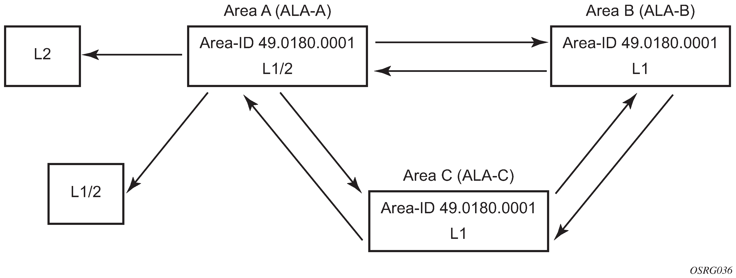
The following shows the command usage to configure a Level 1/2 system.
A:ALA-A>config>router# isis
A:ALA-A>config>router>isis# level-capability level-1/2
IS-IS configuration management tasks
This section describes the IS-IS configuration management tasks.
Disabling IS-IS
The shutdown command disables the IS-IS protocol instance on the router. The configuration settings are not changed, reset, or removed.
Use the following syntax to disable IS-IS on a router.
config>router# isis
    shutdown
Removing IS-IS
The no isis command deletes the IS-IS protocol instance. The IS-IS configuration reverts to the default settings.
Use the following syntax to remove the IS-IS configuration.
config>router#
    no isis
Modifying global IS-IS parameters
You can modify, disable, or remove global IS-IS parameters without shutting down entities. Changes take effect immediately. Modifying the level capability on the global level causes the IS-IS protocol to restart.
The following shows the command usage to modify various parameters.
config>router>isis#  overload timeout 500
    config>router>isis# level-capability level-1/2
    config>router>isis# no authentication-check
    config>router>isis# authentication-key raiderslost
Global modifications output
A:ALA-A>config>router>isis# info
----------------------------------------------
        area-id 49.0180.0001
        area-id 49.0180.0002
        area-id 49.0180.0003
        authentication-key "//oZrvtvFPn06S42lRIJsE" hash
        authentication-type password
        no authentication-check
        overload timeout 500 on-boot
        level 1
            wide-metrics-only
        exit
        level 2
            wide-metrics-only
        exit
        interface "system"
        exit
        interface "ALA-1-2"
            level-capability level-2
            mesh-group 85
        exit
        interface "ALA-1-3"
            level-capability level-1
            interface-type point-to-point
            mesh-group 101
        exit
        interface "ALA-1-5"
            level-capability level-1
            interface-type point-to-point
            mesh-group 85
        exit
        interface "to-103"
            mesh-group 101
        exit
        interface "A-B"
        exit
        interface "A-C"
        exit
----------------------------------------------
A:ALA-A>config>router>isis#
Modifying IS-IS interface parameters
You can modify, disable, or remove interface-level IS-IS parameters without shutting down entities. Changes take effect immediately. Modifying the level capability on the interface causes the IS-IS protocol on the interface to restart.
To remove an interface, issue the no interface ip-int-name command.
To disable an interface, issue the shutdown command in the interface context.
The following shows the command usage for interface IS-IS modification.
config>router# isis
    config>router>isis# interface ALA-1-3
    config>router>isis>if# mesh-group 85
    config>router>isis>if# passive
    config>router>isis>if# lsp-pacing-interval 5000
    config>router>isis>if# exit
    config>router>isis# interface to-103
    config>router>isis>if# hello-authentication-type message-digest
    config>router>isis>if# hello-authentication-key 49ersrule
    config>router>isis>if# exit
Modified interface parameters
A:ALA-A>config>router>isis# info
----------------------------------------------
        area-id 49.0180.0001
        area-id 49.0180.0002
        area-id 49.0180.0003
        authentication-key "//oZrvtvFPn06S42lRIJsE" hash
        authentication-type password
        no authentication-check
        overload timeout 500 on-boot
        level 1
            wide-metrics-only
        exit
        level 2
            wide-metrics-only
        exit
        interface "system"
        exit
        interface "ALA-1-2"
            level-capability level-2
            mesh-group 85
        exit
        interface "ALA-1-3"
            level-capability level-1
            interface-type point-to-point
            lsp-pacing-interval 5000
            mesh-group 85
passive
        exit
        interface "ALA-1-5"
            level-capability level-1
            interface-type point-to-point
            mesh-group 85
        exit
        interface "to-103"
            hello-authentication-key "DvR3l264KQ6vXMTvbAZ1mE" hash
            hello-authentication-type message-digest
            mesh-group 101
        exit
        interface "A-B"
        exit
----------------------------------------------
A:ALA-A>config>router>isis#
Configuring leaking
IS-IS allows a two-level hierarchy to route PDUs. Level 1 areas can be interconnected by a contiguous Level 2 backbone.
The Level 1 link-state database contains information about only that area. The Level 2 link-state database contains information about the Level 2 system and each of the Level 1 systems in the area. A Level 1/2 router contains information about both Level 1 and Level 2 databases. A Level 1/2 router advertises information about its Level 1 area toward the other Level 1/2 or Level 2 (only) routers.
Packets with destinations outside the Level 1 area are forwarded toward the closest Level 1/2 router which, in turn, forwards the packets to the destination area.
Sometimes, the shortest path to an outside destination is not through the closest Level 1/2 router, or, the only Level 1/2 system to forward packets out of an area is not operational. Route leaking provides a mechanism to leak Level 2 information to Level 1 systems to provide routing information about inter-area routes. Then, a Level 1 router has more options to forward packets.
Configure a route policy to leak routers from Level 2 into Level 1 areas in the config>router>policy-options>policy-statement context.
The following shows the command usage to configure prefix list and policy statement parameters in the config>router context.
    config>router>policy-options# prefix-list  loops
    ..>policy-options>prefix-list# prefix 10.1.1.0/24 longer
    ..>policy-options>prefix-list# exit
    ..>policy-options# policy-statement leak
    ..>policy-options>policy-statement# entry 10
    ..>policy-options>policy-statement>entry# from
    ..>policy-options>policy-statement>entry>from# prefix-list loops
    ..>policy-options>policy-statement>entry>from# level 2
    ..>policy-options>policy-statement>entry>from# exit
    ..>policy-options>policy-statement>entry# to
    ..>policy-options>policy-statement>entry>to# level 1
    ..>policy-options>policy-statement>entry>to# exit
    ..>policy-options>policy-statement>entry# action accept
    ..>policy-options>policy-statement>entry>action# exit
    ..>policy-options>policy-statement>entry# exit
    ..>policy-options>policy-statement#exit
    ..>policy-options# commit
    ..>policy-options#
A:ALA-A>config>router>policy-options# info
----------------------------------------------
prefix-list "loops"
prefix 10.1.1.0/24 longer
exit
policy-statement "leak"
entry 10
from
prefix-list "loop"
level 2
exit
to
level 1
exit
action accept
exit
exit
exit
----------------------------------------------
A:ALA-A>config>router>policy-options#
Next, apply the policy to leak routes from Level 2 into Level 1 systems on ALA-A.
config>router#isis
config>router>isis# export leak

A:ALA-A>config>router>isis# info
----------------------------------------------
        area-id 49.0180.0001
        area-id 49.0180.0002
        area-id 49.0180.0003
        authentication-key "//oZrvtvFPn06S42lRIJsE" hash
        authentication-type password
        no authentication-check
        export "leak"
...
----------------------------------------------
A:ALA-A>config>router>isis#
After the policy is applied, create a policy to redistribute external IS-IS routes from Level 1 systems into the Level 2 backbone (see Redistributing external IS-IS routers). In the config>router context, configure the following policy statement parameters:
    config>router>policy-options# begin
    ..>policy-options# policy-statement "isis-ext"
    ..>policy-options>policy-statement# entry 10
    ..>policy-options>policy-statement>entry$ from
    ..>policy-options>policy-statement>entry>from$ external
    ..>policy-options>policy-statement>entry>from# exit
    ..>policy-options>policy-statement>entry# to
    ..>policy-options>policy-statement>entry>to$ level 2
    ..>policy-options>policy-statement>entry>to# exit
    ..>policy-options>policy-statement>entry# action accept
    ..>policy-options>policy-statement>entry>action# exit
    ..>policy-options>policy-statement>entry# exit
    ..>policy-options>policy-statement# exit
    ..>policy-options# commit
A:ALA-A>config>router>policy-options# info
----------------------------------------------
prefix-list "loops"
prefix 10.1.1.0/24 longer
exit
policy-statement "leak"
entry 10
from
prefix-list "loop"
level 2
exit
to
level 1
exit
action accept
exit
exit
exit
policy-statement "isis-ext"
entry 10
from
external
exit
to
level 2
exit
action accept
exit
exit
exit
----------------------------------------------
A:ALA-A>config>router>policy-options#
Redistributing external IS-IS routers
IS-IS does not redistribute Level 1 external routes into Level 2 by default. You must explicitly apply the policy to redistribute external IS-IS routes. Policies are created in the config>router>policy-options context. See Route policies for more information.
The following is a sample policy statement configuration output.
config>router>policy-options# info
----------------------------------------------
            prefix-list "loops"
                    prefix 10.1.1.0/24 longer
            exit
            policy-statement "leak"
                entry 10
                    from
                        prefix-list "loop"
                        level 2
                    exit
                    to
                        level 1
                    exit
                    action accept
                    exit
                exit
            exit
            policy-statement "isis-ext"
                entry 10
                    from
                        external
                    exit
                    to
                        level 2
                    exit
                    action accept
                    exit
                exit
            exit
----------------------------------------------
config>router>policy-options#
IS-IS command reference
Command hierarchies
Configuration commands
Global commands
config
    - router
        - [no] isis [isis-instance]
            - [no] advertise-passive-only
            - advertise-router-capability {area | as}
            - no advertise-router-capability
            - [no] all-l1isis ieee-address
            - [no] all-l2isis ieee-address
            - [no] area-id area-address
            - [no] authentication-check
            - authentication-key [authentication-key | hash-key] [hash | hash2]
            - no authentication-key
            - authentication-type {password | message-digest}
            - no authentication-type
            - [no] csnp-authentication
            - [no] disable-ldp-sync
            - export policy-name [.. policy-name... up to 5 max)]
            - no export
            - export-limit number [log percentage]
            - no export-limit
            - [no] graceful-restart
                - [no] helper-disable
            - [no] hello-authentication
            - [no] iid-tlv-enable
            - [no] ignore-attached-bit
            - import policy-name [policy-name...(up to 5 max)]
            - no import
            - [no] ipv4-routing
            - [no] ipv6-routing {native | mt}
            - ldp-over-rsvp
            - no ldp-over-rsvp
            - loopfree-alternate [remote-lfa]
            - loopfree-alternate remote-lfa [max-cq-cost value]
            - no loopfree-alternate
            - loopfree-alternate-exclude
            - no loopfree-alternate-exclude
            - level {1 | 2}
                - authentication-key [authentication-key | hash-key] [hash | hash2]
                - no authentication-key
                - authentication-type {password | message-digest}
                - no authentication-type
                - [no] csnp-authentication
                - [no] default-ipv6-unicast-metric metric
                - external-preference external-preference
                - no external-preference
                - [no] hello-authentication
                - [no] loopfree-alternate-exclude
                - preference preference
                - no preference
                - [no] psnp-authentication
                - [no] wide-metrics-only
            - level-capability {level-1 | level-2 | level-1/2}
            - lsp-lifetime seconds
            - no lsp-lifetime
            - loopfree-alternate
            - no loopfree-alternate
            - lsp-mtu-size size
            - no lsp-mtu-size
            - lsp-refresh-interval [seconds]
            - no lsp-refresh-interval
            - [no] lsp-wait lsp-wait [lsp-initial-wait [lsp-second-wait]]
            - multi-topology
            - no multi-topology
                -  ipv6-unicast
                - no ipv6-unicast
            - overload [timeout seconds]
            - no overload
            - overload-on-boot [timeout seconds]
            - no overload-on-boot
            - [no] psnp-authentication
            - reference-bandwidth reference-bandwidth
            - no reference-bandwidth
            - segment-routing
            - no segment-routing
                - prefix-sid-range {global | start-label label-value max-index index-value}
                - no prefix-sid-range
                - tunnel-mtu bytes
                - no tunnel-mtu
                - tunnel-table-pref preference
                - no tunnel-table-pref
                - [no] shutdown
            - [no] shutdown
            - [no] spf-wait spf-wait [spf-initial-wait [spf-second-wait]]
            - [no] strict-adjacency-check
            - summary-address {ip-prefix/mask | ip-prefix [netmask]} level [tag tag]
            - no summary-address {ip-prefix/mask | ip-prefix [netmask]}
            - [no] traffic-engineering
Interface commands
config
    - router
        - [no] isis [isis-instance]
            - [no] interface ip-int-name
                - [no] bfd-enable {ipv4}
                - csnp-interval seconds
                - no csnp-interval
                - hello-authentication-key [authentication-key | hash-key] [hash | hash2]
                - no hello-authentication-key
                - hello-authentication-type {password | message-digest}
                - no hello-authentication-type
                - interface-type {broadcast | point-to-point}
                - no interface-type
                - [no] loopfree-alternate-exclude
                -  ipv6-unicast-disable
                -  no ipv6-unicast-disable
                -  level {1 | 2}
                    - hello-authentication-key [authentication-key | hash-key] [hash | hash2]
                    - no hello-authentication-key
                    - hello-authentication-type [password | message-digest]
                    - no hello-authentication-type
                    - hello-interval seconds
                    - no hello-interval
                    - hello-multiplier multiplier
                    - no hello-multiplier
                    - ipv6-unicast-metric metric
                    - no ipv6-unicast-metric
                    - metric ipv4-metric
                    - no metric
                    - [no] passive
                    - priority number
                    - no priority
                - level-capability {level-1 | level-2 | level-1/2}
                - lsp-pacing-interval milli-seconds
                - no lsp-pacing-interval
                - mesh-group [value | blocked]
                - no mesh-group
                - [no] multi-topology
                    - [no] ipv6-unicast
                - ipv4-node-sid index value
                - ipv4-node-sid label value
                - no ipv4-node-sid
                - [no] passive
                - retransmit-interval seconds
                - no retransmit-interval
                - [no] shutdown
                -  tag tag
                - no tag
Show commands
show
    - router
        - isis all
        - isis [isis-instance]
            - adjacency [ip-address | ip-int-name | nbr-system-id] [detail]
            - database [system-id | lsp-id] [detail] [level level]
            - hostname
            - interface [ip-int-name | ip-address] [detail]
            - prefix-sids [ipv4-unicast] [ip-prefix[/prefix-length] [sid sid] [adv-router system-id | hostname]
            - routes [ipv4-unicast | ipv6-unicast | mt mt-id-number] [ip-prefix/prefix-length] [alternative]
            - spf [detail]
            - spf-log [detail]
            - statistics
            - status
            - summary-address [ip-prefix[/prefix-length]]
            - topology [[ipv4-unicast | ipv6-unicast | mt mt-id-number] [detail]]
Clear commands
Debug commands
debug
    - router
        - isis [isis-instance]
            - [no] adjacency [ip-int-name | ip-address | nbr-system-id]
            - [no] cspf
            - [no] graceful-restart
            - interface [ip-int-name | ip-address]
            - no interface
            - leak [ip-address]
            - no leak
            - [no] lsdb [level-number] [system-id | lsp-id]
            - [no] misc
            - packet [packet-type] [ip-int-name | ip-address] [detail]
            - rtm [ip-address]
            - no rtm
            - [no] spf [level-number] [system-id]
Command descriptions
IS-IS configuration commands
Generic commands
isis
Syntax
isis [isis-instance]
no isis [isis-instance]
Context
config>router
Platforms
Supported on all 7210 SAS platforms as described in this document
Description
Commands in this context configure the Intermediate-System-to-Intermediate-System (IS-IS) protocol instance.
The IS-IS protocol instance is enabled with the no shutdown command in the config>router>isis context. Alternatively, the IS-IS protocol instance is disabled with the shutdown command in the config>router>isis context.
The no form of this command deletes the IS-IS protocol instance. Deleting the protocol instance removes all configuration parameters for this IS-IS instance.
The number of IS-IS instances supported on different 7210 platforms are different. Contact a Nokia representative about the supported scaling limits.
Parameters
- isis-instance
Specifies the IS-IS instance.
shutdown
Syntax
[no] shutdown
Context
config>router>isis
config>router>isis>interface
config>router>isis>if>level
config>router>isis>segment-routing
Platforms
Supported on all 7210 SAS platforms as described in this document
Description
The config>router>isis>segment-routing context is supported only on the 7210 SAS-Mxp, 7210 SAS-R6, 7210 SAS-R12, and 7210 SAS-Sx/S 1/10GE.
This command administratively disables an entity. When disabled, an entity does not change, reset, or remove any configuration settings or statistics.
The operational state of the entity is disabled as well as the operational state of any entities contained within. Many objects must be shut down before they may be deleted.
The no form of this command administratively enables an entity.
Default
no shutdown
Special Cases
- IS-IS Global
In the config>router>isis context, the shutdown command disables the IS-IS protocol instance. By default, the protocol is enabled (no shutdown).
- IS-IS Protocol Handling
On all 7210 SAS platforms, IS-IS is created in the no shutdown state.
On the 7210 SAS-Mxp, the protocol is handled as follows.
The config>router>isis command instantiates the protocol in the no shutdown state, and resources are allocated to enable the node to process the protocol.
To deallocate resources, you must issue the configure router isis shutdown and configure router no isis commands to allow the node to boot up correctly after the reboot. It is not sufficient to issue only a configure router isis shutdown command.
The resources are allocated when the first instance of IS-IS is configured, and resources are deallocated when the last instance of the configuration for IS-IS is removed or shut down.
- IS-IS Interface
In the config>router>isis>interface context, the command disables the IS-IS interface. By default, the IS-IS interface is enabled (no shutdown).
- IS-IS Interface and Level
In the config>router>isis>interface>level context, the command disables the IS-IS interface for the level. By default, the IS-IS interface at the level is enabled (no shutdown).
tag
Syntax
tag tag
no tag
Context
config>router>isis>interface
Platforms
Supported on all 7210 SAS platforms as described in this document
Description
This command configures a route tag to the specified IP address of an interface.
Parameters
- tag
Specifies the route tag.
authentication-check
Syntax
[no] authentication-check
Context
config>router>isis
Platforms
Supported on all 7210 SAS platforms as described in this document
Description
This command sets an authentication check to reject PDUs that do not match the type or key requirements.
The default behavior when authentication is configured is to reject all IS-IS protocol PDUs that have a mismatch in either the authentication type or authentication key.
When no authentication-check is configured, authentication PDUs are generated and IS-IS PDUs are authenticated on receipt. However, mismatches cause an event to be generated and will not be rejected.
The no form of this command allows authentication mismatches to be accepted and generate a log event.
Default
authentication-check
authentication-key
Syntax
authentication-key [authentication-key | hash-key] [hash | hash2]
no authentication-key
Context
config>router>isis
config>router>isis>level
Platforms
Supported on all 7210 SAS platforms as described in this document
Description
This command configures the authentication key used to verify PDUs sent by neighboring routers on the interface.
Neighboring routers use passwords to authenticate PDUs sent from an interface. For authentication to work, both the authentication key and the authentication type on a segment must match. The authentication-type statement must also be included.
To configure authentication at the global level, configure this command in the config>router>isis context. When this parameter is configured at the global level, all PDUs are authenticated, including the hello PDU.
To override the global setting for a specific level, configure the authentication-key command in the config>router>isis>level context. When configured within the specific level, hello PDUs are not authenticated.
The no form of this command removes the authentication key.
Default
no authentication-key
Parameters
- authentication-key
Specifies the authentication key. The key can be any combination of ASCII characters up to 255 characters (unencrypted). If spaces are used in the string, enclose the entire string in quotation marks (‟ ”).
- hash-key
Specifies the hash key. The key can be any combination of ASCII characters up to 342 characters (encrypted). If spaces are used in the string, enclose the entire string in quotation marks (‟ ”).
This is useful when a user must configure the parameter, but, for security purposes, the actual unencrypted key value is not provided.
- hash
Keyword to specify the key is entered in an encrypted form. If the hash parameter is not used, the key is assumed to be in a non-encrypted, clear text form. For security, all keys are stored in encrypted form in the configuration file with the hash parameter specified.
- hash2
Keyword to specify the key is entered in a more complex encrypted form. If the hash2parameter is not used, the less encrypted hash form is assumed.
authentication-type
Syntax
authentication-type {password | message-digest}
no authentication
Context
config>router>isis
config>router>isis>level
Platforms
Supported on all 7210 SAS platforms as described in this document
Description
This command enables either simple password or message digest authentication in the global IS-IS or IS-IS level context. Both the authentication key and the authentication type on a segment must match. The authentication-key statement must also be entered.
Configure the authentication type at the global level in the config>router>isis context. Configure or override the global setting by configuring the authentication type using the config>router>isis>level context
The no form of this command disables authentication.
Default
no authentication-type
Parameters
- password
Keyword to specify that simple password (plain text) authentication is required.
- message-digest
Keyword to specify that MD5 authentication in accordance with RFC2104 is required.
bfd-enable
Syntax
[no] bfd-enable {ipv4}
Context
config>router>isis>interface
Platforms
Supported on all 7210 SAS platforms as described in this document
Description
This command enables the use of bidirectional forwarding (BFD) to control IPv4 adjacencies. By enabling BFD on an IPv4 protocol interface, the state of the protocol interface is tied to the state of the BFD session between the local node and the remote node. The parameters used for the BFD are set by the BFD command under the IP interface.
For more information about the protocols and platforms that support BFD, see the 7210 SAS-Mxp, R6, R12, S, Sx, T Router Configuration Guide.
The no form of this command removes BFD from the associated adjacency.
Default
no bfd-enable ipv4
csnp-authentication
Syntax
[no] csnp-authentication
Context
config>router>isis
config>router>isis>level
Platforms
Supported on all 7210 SAS platforms as described in this document
Description
This command enables authentication of individual IS-IS packets of complete sequence number PDUs (CSNP) type.
The no form of this command suppresses authentication of CSNP packets.
csnp-interval
Syntax
csnp-interval seconds
no csnp-interval
Context
config>router>isis>interface
Platforms
Supported on all 7210 SAS platforms as described in this document
Description
This command configures the time interval, in seconds, to send complete sequence number (CSN) PDUs from the interface. IS-IS must send CSN PDUs periodically.
The no form of this command reverts to the default value.
Default
csnp-interval 10 — CSN PDUs are sent every 10 seconds for LAN interfaces.
csnp-interval 5 — CSN PDUs are sent every 5 seconds for point-to-point interfaces.
Parameters
- seconds
Specifies the time interval, in seconds, between successive CSN PDUs sent from this interface, expressed as a decimal integer.
default-ipv6-unicast-metric
Syntax
default-ipv6-unicast-metric metric
no default-ipv6-unicast-metric
Context
config>router>isis>if>
Platforms
Supported on all 7210 SAS platforms as described in this document
Description
This command configures the default metric used for IPv6 routes for both level 1 and level 2 on the interface, only when IS-IS multi-topology is configured.
To calculate the lowest cost to reach a specific destination, each configured level on each interface must have a cost. The costs for each level on an interface may be different. The value specified with this command is used only if the metric is not specified using the ipv6-unicast-metric CLI command under the specific level.
If the metric is not configured, the default of 10 is used unless reference bandwidth is configured.
The no form of this command reverts to the default value.
Default
default-ipv6-unicast-metric 10
Parameters
- metric
Specifies the metric assigned for this level on this interface.
disable-ldp-sync
Syntax
[no] disable-ldp-sync
Context
config>router>isis
Platforms
Supported on all 7210 SAS platforms as described in this document
Description
This command disables the IGP-LDP synchronization feature on all interfaces participating in the OSPF or IS-IS routing protocol.
When this command is executed, IGP immediately advertises the actual value of the link cost for all interfaces which have the IGP-LDP synchronization enabled if the currently advertised cost is different. It then disables IGP-LDP synchronization for all interfaces. This command does not delete the interface configuration. The no form of this command has to be entered to re-enable IGP-LDP synchronization for this routing protocol.
The no form of this command reverts to the default value and re-enables IGP-LDP synchronization on all interfaces participating in the OSPF or IS-IS routing protocol and for which the ldp-sync-timer is configured.
Default
no disable-ldp-sync
export
Syntax
[no] export policy-name [policy-name...up to 32 max]
Context
config>router>isis
Platforms
Supported on all 7210 SAS platforms as described in this document
Description
This command configures export routing policies that determine the routes exported from the routing table to IS-IS.
If no export policy is defined, non IS-IS routes are not exported from the routing table manager to IS-IS.
If multiple policy names are specified, the policies are evaluated in the order they are specified. The first policy that matches is applied. If multiple export commands are issued, the last command entered overrides the previous command. A maximum of five policy names can be specified.
If an aggregate command is also configured in the config>router context, the aggregation is applied before the export policy is applied.
Routing policies are created in the config>router>policy-options context.
The no form of this command removes the specified policy-name, or all policies from the configuration if no policy-name is specified.
Default
no export
Parameters
- policy-name
Specifies the export policy name. Up to five policy names can be specified.
export-limit
Syntax
export-limit number [log percentage]
no export-limit
Context
config>router>isis
Platforms
Supported on all 7210 SAS platforms as described in this document
Description
This command configures the maximum number of routes (prefixes) that can be exported into IS-IS from the route table.
The no form of this command removes the parameters from the configuration.
Default
no export-limit
Parameters
- number
Specifies the maximum number of routes (prefixes) that can be exported into IS-IS from the route table.
- log percentage
Specifies the percentage of the export limit, at which a warning log message and SNMP notification are sent.
external-preference
Syntax
external-preference external-preference
no external-preference
Context
config>router>isis>level
Platforms
Supported on all 7210 SAS platforms as described in this document
Description
This command configures the external route preference for the IS-IS level. This command configures the preference level of either IS-IS level 1 or IS-IS level 2 external routes.
A route can be learned by the router by different protocols, in which case, the costs are not comparable. When this occurs, the preference is used to decide the route to use.
Different protocols should not be configured with the same preference, if this occurs the tiebreaker is base on the default preferences. The following table lists the default preferences.
Route type |
Preference |
Configurable |
|---|---|---|
Direct attached |
0 |
No |
Static-route |
5 |
Yes |
OSPF internal routes |
10 |
No |
IS-IS Level 1 internal |
15 |
Yes 1 |
IS-IS Level 2 internal |
18 |
Yes 1 |
OSPF external |
150 |
Yes |
IS-IS Level 1 external |
160 |
Yes |
IS-IS Level 2 external |
165 |
Yes |
BGP |
170 |
Yes |
If multiple routes are learned with an identical preference using the same protocol, the lowest cost route is used. If multiple routes are learned with an identical preference using the same protocol and the costs (metrics) are equal, the decision of the route to use is determined by the configuration of the ecmp in the config>router context.
Parameters
- external-preference
Specifies the preference for external routes at this level, expressed as a decimal integer.
graceful-restart
Syntax
[no] graceful-restart
Context
config>router>isis
Platforms
Supported on all 7210 SAS platforms as described in this document
Description
This command enables graceful restart helper support for IS-IS. The router acts as a helper to neighbors who are graceful-restart-capable and are restarting.
When the control plane of a graceful-restart-capable router fails, the neighboring routers (graceful-restart helpers) temporarily preserve adjacency information so packets continue to be forwarded through the failed graceful-restart router using the last known routes. If the control plane of the graceful-restart router comes back up within the timer limits, then the routing protocols reconverge to minimize service interruption.
The no form of this command disables graceful restart and removes all graceful restart configurations in the IS-IS instance.
Default
no graceful-restart
helper-disable
Syntax
[no] helper-disable
Context
config>router>isis>graceful-restart
Platforms
Supported on all 7210 SAS platforms as described in this document
Description
This command disables the helper support for graceful restart.
When graceful-restart is enabled, the router can be a helper (meaning that the router is helping a neighbor to restart) or be a restarting router or both. The router supports only helper mode. This facilitates the graceful restart of neighbors but does not act as a restarting router (meaning that the router does not help the neighbors to restart).
The no form of this command enables helper support and is the default when the graceful-restart command is enabled.
Default
no helper-disable
loopfree-alternate-exclude
Syntax
[no] loopfree-alternate
Context
configure>router>isis>level
configure>router>isis>interface
Platforms
Supported on all 7210 SAS platforms as described in this document
Description
This command instructs IGP to exclude a specific interface or all interfaces participating in a specific IS-IS level from the SPF LFA computation. The LFA SPF calculation can therefore be run only where it is not needed.
If an interface is excluded from the LFA SPF in IS-IS, it is excluded in both level 1 and level 2.
The no form of this command reverts to the default value.
Default
no loopfree-alternate-exclude
loopfree-alternate
Syntax
loopfree-alternate [remote-lfa]
loopfree-alternate remote-lfa [max-pq-cost value]
no loopfree-alternate
Context
config>router>isis
Platforms
Supported on all 7210 SAS platforms as described in this document
Description
This command enables the Loop-Free Alternate (LFA) computation by SPF for the IS-IS routing protocol instance.
The IGP SPF is instructed to precompute both a primary next hop and an LFA next hop for every learned prefix. When found, the LFA next-hop is populated into the routing table along with the primary next hop for the prefix.
The IGP LFA SPF uses the remote-lfa option to enable the remote LFA next-hop calculation. When this option is enabled in an IGP instance, SPF performs the remote LFA additional computation following the regular LFA next-hop calculation when the latter results in no protection for one or more prefixes that are resolved to a specific interface.
Remote LFA extends the protection coverage of LFA-FRR to any topology by automatically computing and establishing or tearing down shortcut tunnels (repair tunnels) to a remote LFA node (PQ node). This puts the packets back into the shortest path without looping them to the node that forwarded them over the repair tunnel. A repair tunnel can be an RSVP LSP, an LDP-in-LDP tunnel, or a segment routing tunnel. The use of segment routing repair tunnels is restricted to the remote LFA node.
Unlike the regular LFA algorithm, which is per-prefix, the remote LFA algorithm is a per-link LFA SPF calculation. It provides protection to all destination prefixes that share the protected link by using the neighbor on the other side of the protected link as a proxy for those prefixes.
Default
no loopfree-alternate
Parameters
- remote-lfa
Keyword to enable the remote LFA next-hop calculation by the IGP LFA SPF.
- max-pq-lfa value
Specifies the maximum IGP cost from the router that is performing the remote LFA calculation to the candidate P or Q node.
hello-authentication
Syntax
[no] hello-authentication
Context
config>router>isis
config>router>isis>level
Platforms
Supported on all 7210 SAS platforms as described in this document
Description
This command enables authentication of individual IS-IS packets of the Hello type.
The no form of this command suppresses authentication of Hello packets.
iid-tlv-enable
Syntax
[no] iid-tlv-enable
Context
config>router>isis>graceful-restart
Platforms
Supported on all 7210 SAS platforms as described in this document
Description
This command specifies whether Instance Identifier (IID) TLV is enabled or disabled for this IS-IS instance.
hello-authentication-key
Syntax
hello-authentication-key [authentication-key | hash-key] [hash | hash2]
no hello-authentication-key
Context
config>router>isis>interface
config>router>isis>if>level
Platforms
Supported on all 7210 SAS platforms as described in this document
Description
This command configures the authentication key (password) for hello PDUs. Neighboring routers use the password to verify the authenticity of hello PDUs sent from this interface. Both the hello authentication key and the hello authentication type on a segment must match. The hello-authentication-type must be specified.
To configure the hello authentication key in the interface context use the hello-authentication-key command in the config>router>isis>interface context.
To configure or override the hello authentication key for a specific level, configure the hello-authentication-key in the config>router>isis>interface>level context.
If both IS-IS and hello authentication are configured, hello messages are validated using hello authentication. If only IS-IS authentication is configured, it is used to authenticate all IS-IS (including hello) protocol PDUs.
When the hello authentication key is configured in the config>router>isis>interface context, it applies to all levels configured for the interface.
The no form of this command removes the authentication key from the configuration.
Default
no hello-authentication-key
Parameters
- authentication-key
Specifies the hello authentication key (password). The key can be any combination of ASCII characters up to 254 characters (unencrypted). If spaces are used in the string, enclose the entire string in quotation marks (‟ ”).
- hash-key
Specifies the hash key. The key can be any combination of ASCII characters up to 352 characters (encrypted). If spaces are used in the string, enclose the entire string in quotation marks (‟ ”).
This is useful when a user must configure the parameter, but, for security purposes, the actual unencrypted key value is not provided.
- hash
Keyword to specify the key is entered in an encrypted form. If the hash parameter is not used, the key is assumed to be in a non-encrypted, clear text form. For security, all keys are stored in encrypted form in the configuration file with the hash parameter specified.
- hash2
Keyword to specify the key is entered in a more complex encrypted form. If the hash2parameter is not used, the less encrypted hashform is assumed.
hello-authentication-type
Syntax
hello-authentication-type {password | message-digest}
no hello-authentication-type
Context
config>router>isis>interface
config>router>isis>if>level
Platforms
Supported on all 7210 SAS platforms as described in this document
Description
This command enables hello authentication at either the interface or level context. Both the hello authentication key and the hello authentication type on a segment must match. The hello authentication-key statement must also be included.
To configure the hello authentication type at the interface context, use hello-authentication-type in the config>router>isis>interface context.
To configure or override the hello authentication setting for a specific level, configure the hello-authentication-type in the config>router>isis>interface>level context.
The no form of this command disables hello authentication.
Default
no hello-authentication-type
Parameters
- password
Keyword to specify the simple password (plain text) authentication is required.
- message-digest
Keyword to specify that MD5 authentication in accordance with RFC2104 (HMAC: Keyed-Hashing for Message Authentication) is required.
hello-interval
Syntax
hello-interval seconds
no hello-interval
Context
config>router>isis>if>level
Platforms
Supported on all 7210 SAS platforms as described in this document
Description
This command configures the interval between IS-IS Hello PDUs issued on the interface at this level. The hello-interval command, along with the hello-multiplier command, is used to calculate a hold time, which is communicated to a neighbor in a Hello PDU.
The neighbor hold time is (hello multiplier ✕ hello interval) on non-designated intermediate system broadcast interfaces and point-to-point interfaces and is (hello multiplier ✕ hello interval / 3) on designated intermediate system broadcast interfaces. Hello values can be adjusted for faster convergence, but the hold time should always be > 3 to reduce routing instability.
The no form of this command to reverts to the default value.
Default
hello-interval 3 — Hello interval default for the designated intersystem.
hello-interval 9 — Hello interval default for non-designated intersystems.
Parameters
- seconds
Specifies the hello interval in seconds, expressed as a decimal integer.
hello-multiplier
Syntax
hello-multiplier multiplier
no hello-multiplier
Context
config>router>isis>if>level
Platforms
Supported on all 7210 SAS platforms as described in this document
Description
This command configures a hello multiplier. The hello-multiplier command, along with the hello-interval command, is used to calculate a hold time, which is communicated to a neighbor in a Hello PDU.
The hold time is the time during which the neighbor expects to receive the next Hello PDU. If the neighbor receives a Hello within this time, the hold time is reset. If the neighbor does not receive a Hello within the hold time, it brings the adjacency down.
The neighbor hold time is (hello multiplier ✕ hello interval) on non-designated intermediate system broadcast interfaces and point-to-point interfaces and is (hello multiplier ✕ hello interval / 3) on designated intermediate system broadcast interfaces. Hello values can be adjusted for faster convergence, but the hold time should always be > 3 to reduce routing instability.
The no form of this command reverts to the default value.
Default
hello-multiplier 3
Parameters
- multiplier
Specifies the multiplier for the hello interval, expressed as a decimal integer.
ipv6-unicast-metric
Syntax
ipv6-unicast-metric metric
no ipv6-unicast-metric
Context
config>router>isis>if>level
Platforms
Supported on all 7210 SAS platforms as described in this document
Description
This command configures the default metric used for IPv6 routes for both level 1 and level 2 on the interface, only when IS-IS multi-topology is configured.
To calculate the lowest cost to reach a specific destination, each configured level on each interface must have a cost. The costs for each level on an interface may be different.
If the metric is not configured, the default of 10 is used unless reference bandwidth is configured.
The no form of this command reverts to the default value.
Default
ipv6-unicast-metric 10
Parameters
- metric
Specifies the metric assigned for this level on this interface.
interface
Syntax
[no] interface ip-int-name
Context
config>router>isis
Platforms
Supported on all 7210 SAS platforms as described in this document
Description
Commands in this context configure an IS-IS interface.
When an area is defined, the interfaces belong to that area. Interfaces cannot belong to separate areas.
When the interface is a POS channel, the OSINCP is enabled when the interface is created and removed when the interface is deleted.
The no form of this command removes IS-IS from the interface.
The shutdown command in the config>router>isis>interface context administratively disables IS-IS on the interface without affecting the IS-IS configuration.
Default
no interface
Parameters
- ip-int-name
Specifies the IP interface name created in the config>router>interface context. The IP interface name must already exist.
interface-type
Syntax
interface-type {broadcast | point-to-point}
no interface-type
Context
config>router>isis>interface
Platforms
Supported on all 7210 SAS platforms as described in this document
Description
This command configures the IS-IS interface type as either broadcast or point-to-point.
Use this command to set the interface type of an Ethernet link to point-to-point to avoid having to carry the designated IS-IS overhead if the link is used as a point-to-point.
If the interface type is not known at the time the interface is added to IS-IS, and subsequently the IP interface is bound (or moved) to a different interface type, this command must be entered manually.
The no form of this command reverts to the default value.
Default
interface-type point-to-point — for IP interfaces on SONET channels
interface-type broadcast — for IP interfaces on Ethernet or unknown type physical interfaces
Special Cases
- SONET
Interfaces on SONET channels default to the point-to-point type.
- Ethernet or Unknown
Physical interfaces that are Ethernet or unknown default to the broadcast type.
Parameters
- broadcast
Keyword to configure the interface to maintain this link as a broadcast network.
- point-to-point
Keyword to configure the interface to maintain this link as a point-to-point link.
ipv6-unicast-disable
Syntax
[no] ipv6-unicast-disable
Context
config>router>isis>interface
Platforms
Supported on all 7210 SAS platforms as described in this document
Description
This command disables IS-IS IPv6 unicast routing for the interface.
By default, IPv6 unicast on all interfaces is enabled. However, IPv6 unicast routing on IS-IS is in effect when the config>router>isis>ipv6-routing mt command is configured.
The no form of this command enables IS-IS IPv6 unicast routing for the interface.
ipv4-routing
Syntax
[no] ipv4-routing
Context
config>router>isis
Platforms
Supported on all 7210 SAS platforms as described in this document
Description
This command specifies whether this IS-IS instance supports IPv4.
The no form of this command disables IPv4 on the IS-IS instance.
Default
ipv4-routing
ipv6-routing
Syntax
[no] ipv6-routing {native | mt}
Context
config>router>isis
Platforms
Supported on all 7210 SAS platforms as described in this document
Description
This command enables IPv6 routing.
The no form of this command disables support for IS-IS IPv6 TLVs for IPv6 routing.
Default
no ipv6-routing
Parameters
- native
Keyword that enables IS-IS IPv6 TLVs for IPv6 routing and enables support for native IPv6 TLVs.
- mt
Keyword that enables IS-IS multi-topology TLVs for IPv6 routing. When this parameter is specified, the support for native IPv6 TLVs is disabled.
ldp-over-rsvp
Syntax
[no] ldp-over-rsvp
Context
config>router>isis
Platforms
Supported on all 7210 SAS platforms as described in this document
Description
This command enables LDP over RSVP processing in IS-IS.
The no form of this command disables LDP over RSVP processing.
Default
no ldp-over-rsvp
level
Syntax
level level-number
Context
config>router>isis
config>router>isis>interface
Platforms
Supported on all 7210 SAS platforms as described in this document
Description
Commands in this context configure IS-IS level 1 or level 2 area attributes.
A router can be configured as a level 1, level 2, or level 1-2 system. A level 1 adjacency can be established if there is at least one area address shared by this router and a neighbor. A level 2 adjacency cannot be established over this interface.
Level 1/2 adjacency is created if the neighbor is also configured as a level 1/2 router and has at least one area address in common. A level 2 adjacency is established if there are no common area IDs.
A level 2 adjacency is established if another router is configured as level 2 or a level 1/2 router with interfaces configured as level 1/2 or level 2. Level 1 adjacencies are not established over this interface.
To reset global or interface level parameters to the default, the following commands must be entered independently:
level>no hello-authentication-key
level>no hello-authentication-type
level>no hello-interval
level>no hello-multiplier
level>no metric
level>no passive
level>no priority
Default
level 1 or level 2
Special Cases
- Global IS-IS Level
The config>router>isis context configures default global parameters for both level 1 and level 2 interfaces.
- IS-IS Interface Level
The config>router>isis>interface context configures IS-IS operational characteristics of the interface at level 1 and/or level 2. A logical interface can be configured on one level 1 and one level 2. In this case, each level can be configured independently and parameters must be removed independently.
By default, an interface operates in both level 1 and level 2 modes.
Parameters
- level-number
Specifies the IS-IS level number.
level-capability
Syntax
level-capability {level-1 | level-2 | level-1/2}
no level-capability
Context
config>router>isis
Platforms
Supported on all 7210 SAS platforms as described in this document
Description
This command configures the routing level for an instance of the IS-IS routing process.
An IS-IS router and an IS-IS interface can operate at level 1, level 2, or both level 1 and level 2.
The following table displays configuration combinations and the potential adjacencies that can be formed.
Global level |
Interface level |
Potential adjacency |
|---|---|---|
L 1/2 |
L 1/2 |
Level 1 and/or Level 2 |
L 1/2 |
L 1 |
Level 1 only |
L 1/2 |
L 2 |
Level 2 only |
L 2 |
L 1/2 |
Level 2 only |
L 2 |
L 2 |
Level 2 only |
L 2 |
L 1 |
none |
L 1 |
L 1/2 |
Level 1 only |
L 1 |
L 2 |
none |
L 1 |
L 1 |
Level 1 only |
The no form of this command removes the level capability from the configuration.
Default
level-capability level-1/2
Special Cases
- IS-IS Router
In the config>router>isis context, changing the level capability performs a restart on the IS-IS protocol instance.
- IS-IS Interface
In the config>router>isis>interface context, changing the level capability performs a restart of IS-IS on the interface.
Parameters
- level-1
Keyword to specify the router or interface can operate at level 1only.
- level-2
Keyword to specify the router or interface can operate at level 2 only.
- level-1/2
Keyword to specify the router or interface can operate at both level 1 and level 2.
lsp-pacing-interval
Syntax
lsp-pacing-interval milliseconds
no lsp-pacing-interval
Context
config>router>isis>interface
Platforms
Supported on all 7210 SAS platforms as described in this document
Description
This command configures the interval between LSP PDUs sent from this interface.
To avoid bombarding adjacent neighbors with excessive data, pace the Link State Protocol Data Units (LSPs). If a value of zero is configured, no LSPs are sent from the interface.
The no form of this command reverts to the default value.
Default
lsp-pacing-interval 100
Parameters
- milliseconds
Specifies the interval in milliseconds that IS-IS LSPs can be sent from the interface, expressed as a decimal integer.
lsp-lifetime
Syntax
lsp-lifetime seconds
no lsp-lifetime
Context
config>router>isis
Platforms
Supported on all 7210 SAS platforms as described in this document
Description
This command specifies the time interval that LSPs originated by the router are considered valid by other routers in the domain.
Each LSP received is maintained in an LSP database until the LSP lifetime expires, unless the originating router refreshes the LSP. By default, each router refreshes its LSPs every 20 minutes (1200 seconds), to ensure that other routers do not age out the LSP.
The LSP refresh timer is derived using the following formula: lsp-lifetime value / 2
The no form of this command reverts to the default value.
Default
lsp-lifetime 1200
Parameters
- seconds
Specifies the interval, in seconds, that LSPs originated by the router are considered valid by other routers in the domain.
lsp-mtu-size
Syntax
lsp-mtu-size size
no lsp-mtu-size
Context
config>router>isis
Platforms
Supported on all 7210 SAS platforms as described in this document
Description
This command configures the LSP MTU size. If the MTU size is changed from the default using the CLI or SNMP, IS-IS must be restarted for the change to take effect. This can be done by performing a shutdown command and then a no shutdown command in the config>router>isis context.
If the MTU size is changed from the default value by using the exec command to execute a configuration file with the changed value, IS-IS automatically bounces before the change takes effect.
The no form of this command reverts to the default value.
Default
lsp-mtu-size 1492
Parameters
- size
Specifies the LSP MTU size.
lsp-refresh-interval
Syntax
lsp-refresh-interval [seconds]
no lsp-refresh-interval
Context
config>router>isis
Description
This command configures the IS-IS LSP refresh timer interval. The value specified for lsp-lifetime must be considered when configuring the lsp-refresh-interval. The LSP refresh interval cannot be greater than 90% of the LSP lifetime.
The no form of this command reverts to the default (600 seconds); however, if the configured value is greater than 90% of the LSP lifetime, the command is rejected. For example, if the LSP lifetime is 400, the no lsp-refresh-interval command is rejected.
Default
lsp-refresh-interval 600
Parameters
- seconds
Specifies the refresh interval.
lsp-wait
Syntax
lsp-wait lsp-wait [lsp-initial-wait [lsp-second-wait]]
Context
config>router>isis
Platforms
Supported on all 7210 SAS platforms as described in this document
Description
This command customizes the throttling of IS-IS LSP-generation. Timers that determine when to generate the first, second, and subsequent LSPs can be controlled using this command.
Subsequent LSPs are generated at increasing intervals of the lsp-second-wait timer until a maximum value is reached.
Parameters
- lsp-max-wait
Specifies the maximum interval, in seconds, between two consecutive occurrences of an LSP being generated.
- lsp-initial-wait
Specifies the initial LSP generation delay, in seconds.
- lsp-second-wait
Specifies the hold time, in seconds, between the first and second LSP generation.
mesh-group
Syntax
mesh-group {value | blocked}
no mesh-group
Context
config>router>isis>interface
Platforms
Supported on all 7210 SAS platforms as described in this document
Description
This command assigns an interface to a mesh group. Mesh groups limit the amount of flooding that occurs when a new or changed LSP is advertised throughout an area.
All routers in a mesh group should be fully meshed. When LSPs need to be flooded, only a single copy is received instead of a copy for each neighbor.
To create a mesh group, configure the same mesh group value for each interface that is part of the mesh group. All routers must have the same mesh group value configured for all interfaces that are part of the mesh group.
To prevent an interface from flooding LSPs, the optional blocked parameter can be specified.
Configure mesh groups carefully. It is easy to created isolated islands that do not receive updates as (other) links fail.
The no form of this command removes the interface from the mesh group.
Default
no mesh-group
Parameters
- value
Specifies the unique decimal integer value distinguishes this mesh group from other mesh groups on this or any other router that is part of this mesh group.
- blocked
Keyword that prevents an interface from flooding LSPs.
multi-topology
Syntax
[no] multi-topology
Context
config>router>isis
Platforms
Supported on all 7210 SAS platforms as described in this document
Description
This command enables IS-IS multi-topology support.
The no form of this command disables multi-topology support.
Default
no multi-topology
ipv6-unicast
Syntax
[no] ipv6-unicast
Context
config>router>isis>multi-topology
Platforms
Supported on all 7210 SAS platforms as described in this document
Description
This command enables multi-topology TLVs.
The no form of this command disables multi-topology TLVs.
metric
Syntax
metric ipv4-metric
no metric
Context
config>router>isis>if>level
Platforms
Supported on all 7210 SAS platforms as described in this document
Description
This command configures the metric used for the level on the interface.
To calculate the lowest cost to reach a specific destination, each configured level on each interface must have a cost. The costs for each level on an interface may be different.
If the metric is not configured, the default of 10 is used unless reference bandwidth is configured.
The no form of this command reverts to the default value.
Default
metric 10
Parameters
- ipv4-metric
Specifies the metric assigned for this level on this interface.
advertise-passive-only
Syntax
[no] advertise-passive-only
Context
config>router>isis
Platforms
Supported on all 7210 SAS platforms as described in this document
Description
This command enables IS-IS to advertise only prefixes that belong to passive interfaces.
The no form of this command disables IS-IS to advertise only prefixes that belong to passive interfaces.
advertise-router-capability
Syntax
advertise-router-capability {area | as}
no advertise-router-capability
Context
config>router>isis
Platforms
7210 SAS-Mxp
Description
This command enables advertisement of the capabilities of a router to its neighbors for informational and troubleshooting purposes. A TLV, as defined in RFC 4971, advertises the TE Node Capability Descriptor capability.
The area and as parameters control the scope of the capability advertisements.
The no form of this command disables this advertisement capability.
Default
no advertise-router-capability
Parameters
- area
Keyword specifying advertisement only within the area of origin.
- as
Keyword specifying advertisement throughout the entire autonomous system.
all-l1isis
Syntax
[no] all-l1isis ieee-address
Context
config>router>isis
Platforms
Supported on all 7210 SAS platforms as described in this document
Description
This command specifies the MAC address to use for all layer 1 IS-IS routers. The MAC address should be a multicast address. Run the /no shutdown command on the IS-IS instance to make the change operational.
Default
no all-l1isis
(The MAC address, 01-80-C2-00-02-11, is used in the IS-IS base instance ID (ID==0). This cannot be modified by the user.)
Parameters
- ieee-address
Specifies the destination MAC address for all layer 1 IS-IS neighbors on the link for this IS-IS instance.
all-l2isis
Syntax
[no] all-l2isis ieee-address
Context
config>router>isis
Platforms
Supported on all 7210 SAS platforms as described in this document
Description
This command specifies the MAC address to use for all layer 2 IS-IS routers. The MAC address should be a multicast address. Run the shutdown/no shutdown command on the IS-IS instance to make the change operational.
Default
no all-l2isis
(The MAC address, 01-80-C2-00-01-00, is used in the IS-IS base instance ID (ID==0). This cannot be modified by the user.)
Parameters
- ieee-address
Specifies the destination MAC address for all layer 2 IS-IS neighbors on the link for this IS-IS instance.
area-id
Syntax
[no] area-id area-address
Context
config>router>isis
Platforms
Supported on all 7210 SAS platforms as described in this document
Description
This command configures the area ID portion of NSAP addresses, which identifies a point of connection to the network, such as a router interface, and is called a Network Service Access Point (NSAP). Addresses in the IS-IS protocol are based on the ISO NSAP addresses and Network Entity Titles (NETs), not IP addresses. This command was previously named the net network-entity-title command.
A maximum of 3 area addresses can be configured.
NSAP addresses are divided into the following parts (only the area ID is configurable):
Area ID
This is a field of variable length, between 1 and 13 bytes. This includes the Authority and Format Identifier (AFI) as the most significant byte and the area ID.
System ID
This is a six-byte system identification. This value is not configurable. The system ID is derived from the system or router ID.
Selector ID
This is a one-byte selector identification that must contain zeros when configuring a NET. This value is not configurable. The selector ID is always 00.
The NET is constructed like an NSAP, but the selector byte contains a 00 value. NET addresses are exchanged in hello and LSP PDUs. All net addresses configured on the node are advertised to its neighbors.
For level 1 interfaces, neighbors can have different area IDs, but they must have at least one area ID (AFI + area) in common. Sharing a common area ID, they become neighbors and area merging between the potentially different areas can occur.
For level 2 (only) interfaces, neighbors can have different area IDs. However, if they have no area IDs in common, they become only level 2 neighbors, and level 2 LSPs are exchanged.
For level 1 and level 2 interfaces, neighbors can have different area IDs. If they have at least one area ID (AFI + area) in common, they become neighbors. In addition to exchanging level 2 LSPs, area merging between potentially different areas can occur.
If multiple area-id commands are entered, the system ID of all subsequent entries must match the first area address.
The no form of this command removes the area address.
Parameters
- area-address
Specifies the 1- to 13-byte address. Of the total 20 bytes comprising the NET, only the first 13 bytes can be manually configured. As few as one byte can be entered or, at most, 13 bytes. If less than 13 bytes are entered, the rest is padded with zeros.
overload
Syntax
overload [timeout seconds]
no overload
Context
config>router>isis
Platforms
Supported on all 7210 SAS platforms as described in this document
Description
This command administratively sets the IS-IS router to operate in the overload state for a specific time period or indefinitely.
During normal operation, the router may be forced to enter an overload state because of a lack of resources. When in the overload state, the router is only used if the destination is reachable by the router and is not used for other transit traffic.
If a time period is specified, the overload state persists for the configured length of time. If no time is specified, the overload state operation is maintained indefinitely.
The overload command can be useful in circumstances where the router is overloaded or used before executing a shutdown command to divert traffic around the router.
The no form of this command causes the router to exit the overload state.
Default
no overload
Parameters
- seconds
Specifies the time, in seconds, that this router must operate in overload state.
overload-on-boot
Syntax
overload-on-boot [timeout seconds]
no overload-on-boot
Context
config>router>isis
Platforms
Supported on all 7210 SAS platforms as described in this document
Description
When in an overload state, the router is used only if there is no other router to reach the destination. This command configures the IGP upon bootup in the overload state until one of the following events occurs:
the timeout timer expires
a manual override of the current overload state is entered using the config router isis no overload command
The no overload command does not affect the overload-on-boot command function.
If no timeout is specified, IS-IS goes into overload indefinitely after a reboot. After the reboot, the IS-IS status displays a permanent overload state:
Layer 1 LSDB Overload: Manual on boot (Indefinitely in overload)
Layer 2 LSDB Overload: Manual on boot (Indefinitely in overload)
This state can be cleared using the no overload command.
When specifying a timeout value, IS-IS goes into overload for the configured timeout after a reboot. After the reboot, the IS-IS status displays the remaining time the system stays in overload:
Layer 1 LSDB Overload: Manual on boot (Overload Time Left: 17)
Layer 2 LSDB Overload: Manual on boot (Overload Time Left: 17)
The overload state can be cleared before the timeout expires using the no overload command.
Use the show router ospf status or show router isis status commands to display the administrative and operational state, as well as all timers.
The no form of this command removes the overload-on-boot functionality from the configuration.
Default
no overload-on-boot
Parameters
- timeout seconds
Specifies the number of seconds the router remains in the overload state after rebooting.
ipv4-node-sid
Syntax
ipv4-node-sid index value
ipv4-node-sid label value
no ipv4-node-sid
Context
config>router>isis>interface
Platforms
7210 SAS-Mxp, 7210 SAS-R6, 7210 SAS-R12, and 7210 SAS-Sx/S 1/10GE
Description
This command assigns a node SID index or label value to the prefix representing the primary address of an IPv4 network interface of type loopback. Only a single node SID can be assigned to an interface. The secondary address of an IPv4 interface cannot be assigned a node SID index and does not inherit the SID of the primary IPv4 address.
This command fails if the network interface is not of type loopback, or if the interface is defined in an IES or a VPRN context. Assigning an identical SID index or label value to the same interface in two different IGP instances is not allowed within the same node.
The value of the label or index SID is extracted from the range configured for this IGP instance. When using the global mode of operation, a new segment routing module checks that the same index or label value is not assigned to more than one loopback interface address. When using the per-instance mode of operation, this check is not required because the index and label ranges of the various IGP instances are not allowed to overlap.
The no form of this command reverts to the default value.
Default
no ipv4-node-sid
Parameters
- index value
Specifies the IPv4 SID node index value.
- label value
Specifies the IPv4 SID node label value.
passive
Syntax
[no] passive
Context
config>router>isis>interface
config>router>isis>if>level
Platforms
Supported on all 7210 SAS platforms as described in this document
Description
This command adds the passive attribute, with which the interface is advertised as an IS-IS interface without running the IS-IS protocol. Normally, only interface addresses that are configured for IS-IS are advertised as IS-IS interfaces at the level that they are configured.
When the passive mode is enabled, the interface or the interface at the level ignores ingress IS-IS protocol PDUs and does not transmit IS-IS protocol PDUs.
The no form of this command removes the passive attribute.
Default
passive — service interfaces are passive no passive — all other interfaces are not passive
Special Cases
- Service Interfaces
Service interfaces (defined using the service-prefix command in the config>router context) are passive by default.
- All other Interfaces
All other interfaces are not passive by default.
preference
Syntax
preference preference
no preference
Context
config>router>isis>level
Platforms
Supported on all 7210 SAS platforms as described in this document
Description
This command configures the preference level of either IS-IS level 1 or IS-IS level 2 internal routes.
A route can be learned by the router from different protocols, in which case the costs are not comparable. When this occurs, the preference is used to decide which route is used.
Different protocols should not be configured with the same preference. If this occurs the tiebreaker is based on the default preferences listed in the following table.
|
Route type |
Preference |
Configurable |
|---|---|---|
|
Direct attached |
0 |
No |
|
Static-route |
5 |
Yes |
|
OSPF internal routes |
10 |
No |
|
IS-IS level 1 internal |
15 |
Yes |
|
IS-IS level 2 internal |
18 |
Yes |
|
OSPF external |
150 |
Yes |
|
IS-IS level 1 external |
160 |
Yes 2 |
|
IS-IS level 2 external |
165 |
Yes 2 |
|
BGP |
170 |
Yes |
Parameters
- preference
Specifies the preference for external routes at this level, expressed as a decimal integer.
priority
Syntax
priority number
no priority
Context
config>router>isis>if>level
Platforms
Supported on all 7210 SAS platforms as described in this document
Description
This command configures the priority of the IS-IS router interface for designated router election on a multi-access network.
This priority is included in hello PDUs transmitted by the interface on a multi-access network. The router with the highest priority is the preferred designated router. The designated router is responsible for sending LSPs with regard to this network and the routers that are attached to it.
The no form of this command reverts to the default value.
Default
priority 64
Parameters
- number
Specifies the priority for this interface at this level.
psnp-authentication
Syntax
[no] psnp-authentication
Context
config>router>isis
config>router>isis>level
Platforms
Supported on all 7210 SAS platforms as described in this document
Description
This command configures authentication of individual IS-IS packets of partial sequence number PDU (PSNP) type.
The no form of this command suppresses authentication of PSNP packets.
reference-bandwidth
Syntax
reference-bandwidth reference-bandwidth
no reference-bandwidth
Context
config>router>isis
Platforms
Supported on all 7210 SAS platforms as described in this document
Description
This command configures the reference bandwidth that provides the basis of bandwidth relative costing.
To calculate the lowest cost to reach a specific destination, each configured level on each interface must have a cost. If the reference bandwidth is defined, the cost is calculated using the following formula:
cost = reference-bandwidthbandwidth
If the reference bandwidth is configured as 10 Gbytes (10 000 000 000), a 100 Mb/s interface has a default metric of 100. For metrics in excess of 63 to be configured, wide metrics must be deployed (see the wide-metrics-only command).
If the reference bandwidth is not configured, all interfaces have a default metric of 10.
The no form of this command reverts to the default value.
Default
no reference-bandwidth
Parameters
- reference-bandwidth
Specifies the reference bandwidth in kilobits per second, expressed as a decimal integer.
retransmit-interval
Syntax
retransmit-interval seconds
no retransmit-interval
Context
config>router>isis>interface
Platforms
Supported on all 7210 SAS platforms as described in this document
Description
This command configures the minimum time between LSP PDU retransmissions on a point-to-point interface.
The no form of this command reverts to the default value.
Default
retransmit-interval 100
Parameters
- seconds
Specifies the interval, in seconds, that IS-IS LSPs can be sent on the interface.
segment-routing
Syntax
segment-routing
no segment-routing
Context
config>router>isis
Platforms
7210 SAS-Mxp, 7210 SAS-R6, 7210 SAS-R12, and 7210 SAS-Sx/S 1/10GE
Description
Commands in this context configure segment routing (SR) parameters within an IGP instance.
SR adds to IS-IS routing protocols the ability to perform shortest path routing and source routing using the concept of abstract segment. A segment can represent a local prefix of a node, a specific adjacency of the node (interface/next-hop), a service context, or a specific explicit path over the network. For each segment, the IGP advertises a segment identifier (SID).
When SR is used with the MPLS data plane, the SID is used as a standard MPLS label. A router forwarding a packet using segment routing pushes one or more MPLS labels.
SR using MPLS labels is used in both shortest path routing applications and in traffic engineering applications. The commands in the segment-routing context configure the shortest path forwarding application.
After SR is configured in the IS-IS instance, the router performs the following operations.
Advertises the SR capability sub-TLV to routers in all areas and levels of this IGP instance. However, only neighbors with which it established an adjacency interpret the SID/label range information and use it to calculate the label to swap to or push for a specific resolved prefix SID.
Advertises the assigned index for each configured node SID in the new prefix SID sub-TLV with the N-flag (node-SID flag) set. The SR module then programs the incoming label map (ILM) with a pop operation for each local node SID in the datapath.
Assigns and advertises automatically an adjacency SID label for each formed adjacency over a network IP interface in the new adjacency SID sub-TLV. The SR module programs the incoming label map (ILM) with a pop operation, with a swap to an implicit null label operation, for each advertised adjacency SID.
Resolves received prefixes, and if a prefix SID sub-TLV exists, the SR module programs the ILM with a swap operation and also an LTN with a push operation both pointing to the primary/LFA NHLFE. An SR tunnel is also added to the TTM.
When SR is enabled in an IGP instance, the main SPF and LFA SPF are computed and the primary next hop and LFA backup next hop for a received prefix are added to the RTM without the label information advertised in the prefix SID sub-TLV.
The no form of this command reverts to the default value.
prefix-sid-range
Syntax
prefix-sid-range {global | start-label label-value max-index index-value}
no prefix-sid-range
Context
config>router>isis>segment-routing
Platforms
7210 SAS-Mxp, 7210 SAS-R6, 7210 SAS-R12, and 7210 SAS-Sx/S 1/10GE
Description
This command configures the prefix SID index range and offset label value for an IGP instance.
The user must configure the prefix SID index range and the offset label value that this IGP instance uses. Because each prefix SID represents a network global IP address, the SID index for a prefix must be unique in the network. Therefore, all routers in the network configure and advertise the same prefix SID index range for an IGP instance. However, the label value used by each router to represent this prefix, that is, the label programmed in the ILM, can be local to that router by the use of an offset label, referred to as a start label, as in the following:
The label operation in the network becomes similar to LDP when operating in the independent label distribution mode (RFC 5036), with the difference that the label value used to forward a packet to each downstream router is computed by the upstream router based on the advertised prefix SID index using the preceding formula.
There are two mutually exclusive modes of operation for the prefix SID range on the router.
In the global mode of operation, the global value is configured and this IGP instance assumes that the start label value is the lowest label value in the SRGB, and the prefix SID index range size is equal to the range size of the SRGB. When one IGP instance selects the global option for the prefix SID range, all IGP instances on the system are restricted to do the same. The user must shut down the SR context and delete the prefix-sid-range command in all IGP instances to change the SRGB. After the SRGB is changed, the user must re-enter the prefix-sid-range command. The SRGB range change fails if an already allocated SID index or label goes out of range.
In the per-instance mode of operation, the user partitions the SRGB into non-overlapping sub-ranges among the IGP instances. The user therefore configures a subset of the SRGB by specifying the start label value and the prefix SID index range size. All resulting net label values (start-label + index} must be within the SRGB or the configuration fails.
The code checks for overlaps of the resulting net label value range across IGP instances and strictly enforces that these ranges do not overlap. The user must shut down the SR context of an IGP instance to change the SID index or label range of that IGP instance using theprefix-sid-range command.
Any range change fails if an already allocated SID index or label goes out of range. The user can, however, change the SRGB on the fly as long as it does not reduce the current per-IGP instance SID index or label range defined in the prefix-sid-range command. Otherwise, the user must shut down the SR context of the IGP instance and delete and reconfigure the prefix-sid-range command.
The no form of this command reverts to the default value.
Default
no prefix-sid-range
Parameters
- global
Keyword to enable global operation mode.
- start-label label-value
Specifies the label offset for the SR label range of this IGP instance.
- max-index index-value
Specifies the maximum value of the prefix SID index range for this IGP instance.
tunnel-mtu
Syntax
tunnel-mtu bytes
no tunnel-mtu
Context
config>router>isis>segment-routing
Platforms
7210 SAS-Mxp, 7210 SAS-R6, 7210 SAS-R12, and 7210 SAS-Sx/S 1/10GE
Description
This command configures the MTU of all SR tunnels within each IGP instance.
The MTU of an SR tunnel populated into the TTM is determined in the same way as for an IGP tunnel; for example, LDP LSP, based on the outgoing interface MTU minus the label stack size. Remote LFA can add at least two more labels to the tunnel for a total of three labels. There is no default value. If the user does not configure an SR tunnel MTU, IGP determines the MTU.
The MTU of the SR tunnel in bytes is determined as follows:
Where:
Cfg_SR_MTU is the MTU configured by the user for all SR tunnels within a specific IGP instance using this CLI command. If no value is configured, the SR tunnel MTU is determined by the IGP_Tunnel_MTU calculated value.
IGP_Tunnel_MTU is the minimum of the IS-IS or OSPF interface MTU among all the ECMP paths or among the primary and LFA backup paths of this SR tunnel.
frr-overhead is set to 1 if segment-routing and remote-lfa options are enabled in the IGP instance. Otherwise, it is set to 0.
The SR tunnel MTU is dynamically updated when any of the preceding parameters that are used in its calculation change. This includes when the set of the tunnel next hops changes, or the user changes the configured SR MTU or interface MTU value.
The no form of this command reverts to the default value.
Default
no tunnel-mtu
Parameters
- bytes
Specifies the size of the MTU in bytes.
tunnel-table-pref
Syntax
tunnel-table-pref preference
no tunnel-table-pref
Context
config>router>isis>segment-routing
Platforms
7210 SAS-Mxp, 7210 SAS-R6, 7210 SAS-R12, and 7210 SAS-Sx/S 1/10GE
Description
This command configures the TTM preference of the shortest path SR tunnels created by the IGP instance. The TTM preference is used in the case of VPRN auto-bind or BGP transport tunnels when the new tunnel binding commands are configured to the any value, which parses the TTM for tunnels in the protocol preference order. Either use the global TTM preference or list the tunnel types to use. When listing the tunnel types, the TTM preference is used to select one type over the other. In both cases, a fall-back to the next preferred tunnel type is performed if the selected one fails. A reversion to a more preferred tunnel type is performed as soon as one is available.
The segment routing module adds an SR tunnel entry to the TTM for each resolved remote node SID prefix and programs the datapath that has the corresponding LTN with the push operation pointing to the primary and LFA backup NHLFEs.
The default preference for shortest path SR tunnels in the TTM is set lower than LDP tunnels but higher than BGP tunnels to allow controlled migration of customers without disrupting their current deployment when they enable segment routing. The following is the setting of the default preference of the various tunnel types. This includes the preference of SR tunnels based on the shortest path (referred to as SR-ISIS).
The global default TTM preference for the tunnel types is as follows:
ROUTE_PREF_RSVP 7
ROUTE_PREF_SR_TE 8
ROUTE_PREF_LDP 9
ROUTE_PREF_OSPF_TTM 10
ROUTE_PREF_ISIS_TTM 11
ROUTE_PREF_BGP_TTM 12
ROUTE_PREF_GRE 255
The default value for SR-ISIS is the same regardless of whether one or more IS-IS instances programmed a tunnel for the same prefix. The selection of an SR tunnel in this case is based on the lowest IGP instance ID.
The no form of this command reverts to the default value.
Default
no tunnel-table-pref
Parameters
- preference
Specifies an integer value that represents the preference of IS-IS SR tunnels in the TTM.
spf-wait
Syntax
[no] spf-wait spf-wait [spf-initial-wait [spf-second-wait]]
Context
config>router>isis
Platforms
Supported on all 7210 SAS platforms as described in this document
Description
This command defines the maximum interval between two consecutive SPF calculations.
Timers that determine when to initiate the first, second, and subsequent SPF calculations after a topology change occurs can be controlled using this command. Subsequent SPF runs (if required) occur at exponentially increasing intervals of the spf-second-wait interval. For example, if the spf-second-wait interval is 1000, the next SPF runs after 2000 milliseconds, and the next SPF runs after 4000 milliseconds, and so on, until it reaches the spf-wait value. The SPF interval stays at the spf-wait value until there are no more SPF runs scheduled in that interval. After a full interval without any SPF runs, the SPF interval drops back to spf-initial-wait.
Default
no spf-wait
Parameters
- spf-wait
Specifies the maximum interval, in seconds, between two consecutive SPF calculations.
- spf-initial-wait
Specifies the initial SPF calculation delay, in milliseconds, after a topology change.
- spf-second-wait
Specifies the hold time, in milliseconds, between the first and second SPF calculation.
strict-adjacency-check
Syntax
[no] strict-adjacency-check
Context
config>router>isis
Platforms
Supported on all 7210 SAS platforms as described in this document
Description
This command enables strict checking of address families (IPv4 and IPv6) for IS-IS adjacencies.
When enabled, adjacencies do not come up unless both routers have exactly the same address families configured. An existing adjacency that has unmatched address families is torn down. This command is used to prevent black-holing traffic when IPv4 and IPv6 topologies are different. When disabled (no strict-adjacency-check) a BFD session failure for either IPv4 or Ipv6 causes the routes for the other address family to be removed as well.
When disabled, both routers only need to have one common address family to establish the adjacency.
Default
no strict-adjacency-check
summary-address
Syntax
summary-address {ip-prefix/mask | ip-prefix [netmask]} level [tag tag]
no summary-address {ip-prefix/mask | ip-prefix [netmask]}
Context
config>router>isis
Platforms
Supported on all 7210 SAS platforms as described in this document
Description
This command enables summary addresses.
Parameters
- ip-prefix/mask
Specifies information for the specified IP prefix and mask length.
- netmask
Specifies the subnet mask, in dotted decimal notation.
- level
Specifies IS-IS level area attributes.
- tag tag
Assigns an OSPF, RIP, or IS-IS tag to routes matching the entry.
ignore-attached-bit
Syntax
[no] ignore-attached-bit
Context
config>router>isis
Platforms
Supported on all 7210 SAS platforms as described in this document
Description
This command configures IS-IS to suppress the installation of default routes.
The no form of this command removes suppression of default route installation.
Default
no ignore-attached-bit
import
Syntax
import policy-name [policy-name...(up to 5 max)]
no import
Context
config>router>isis
Platforms
7210 SAS-Mxp
Description
This command specifies up to five route polices as IS-IS import policies.
When a prefix received in an IS-IS LSP is accepted by an entry in an IS-IS import policy, it is installed in the routing table if it is the most preferred route to the destination.
When a prefix received in an IS-IS LSP is rejected by an entry in an IS-IS import policy, it is not installed in the routing table, even if it has the lowest preference value among all the routes to that destination.
The flooding of LSPs is unaffected by IS-IS import policy actions.
The no form of this command removes all policies from the configuration.
Default
no import
Parameters
- policy-name
Specifies the import route policy name. Allowed values are any string up to 32 characters, composed of printable, 7-bit ASCII characters. If the string contains special characters (#, $, spaces, and so on), the entire string must be enclosed within double quotes. The specified names must already be defined.
traffic-engineering
Syntax
[no] traffic-engineering
Context
config>router>isis
Platforms
Supported on all 7210 SAS platforms as described in this document
Description
This command configures traffic-engineering and determines if IGP shortcuts are required.
The no form of this command disables traffic-engineered route calculations.
Default
no traffic-engineering
wide-metrics-only
Syntax
[no] wide-metrics-only
Context
config>router>isis>level
Platforms
Supported on all 7210 SAS platforms as described in this document
Description
This command enables the exclusive use of wide metrics in the LSPs for the level number. Narrow metrics can have values between 1 and 63. IS-IS can generate two TLVs, one for the adjacency and one for the IP prefix. To support traffic engineering, wider metrics are required. When wide metrics are used, a second pair of TLVs are added for the adjacency and the IP prefix.
By default, both sets of TLVs are generated. When the wide-metrics-only command is configured, IS-IS only generates the pair of TLVs with wide metrics for that level.
The no form of this command reverts to the default value.
Show commands
isis
Syntax
isis all
isis [isis-instance]
Context
show>router
Platforms
Supported on all 7210 SAS platforms as described in this document
Description
Commands in this context display information for a specified IS-IS instance.
The number of IS-IS instances supported is different for each 7210 SAS platform. Contact a Nokia representative for information about the supported scaling limits.
Parameters
- all
Keyword to display information for all IS-IS instances on the specified router.
- instance-id
Specifies the instance ID for an IS-IS instance.
adjacency
Syntax
adjacency [ip-address | ip-int-name | nbr-system-id] [detail]
Context
show>router>isis
Platforms
Supported on all 7210 SAS platforms as described in this document
Description
This command displays information about IS-IS neighbors. When no ip-address, ip-int-name, or nbr-system-id values are specified, all adjacencies display.
Parameters
- ip-address
Displays only adjacencies with the specified interface.
- ip-int-name
Displays only adjacencies with the specified interface.
- nbr-system-id
Displays only the adjacency with the specified ID.
- detail
Displays all output displays in the detailed format.
Output
The following output is an example of IS-IS neighbor adjacency information, and Output fields: IS-IS adjacency describes the output fields.
Sample output*A:Dut-A# show router isis adjacency
===============================================================================
Router Base ISIS Instance 1 Adjacency
===============================================================================
System ID Usage State Hold Interface MT Enab
-------------------------------------------------------------------------------
Dut-B L1 Up 2 ip-3FFE::A0A:101 Yes
Dut-B L2 Up 2 ip-3FFE::A0A:101 Yes
Dut-F L1L2 Up 5 ies-1-3FFE::A0A:1501 Yes
-------------------------------------------------------------------------------
Adjacencies : 3
===============================================================================
*A:Dut-A#
*A:ALA-A# show router isis adjacency 180.0.7.12
===============================================================================
Router Base ISIS Instance 1 Adjacency
===============================================================================
System ID Usage State Hold Interface
-------------------------------------------------------------------------------
asbr_east L2 Up 25 if2/5
-------------------------------------------------------------------------------
Adjacencies : 1
===============================================================================
*A:ALA-A#
*A:ALA-A# show router isis adjacency if2/5
===============================================================================
Router Base ISIS Instance 1 Adjacency
===============================================================================
System ID Usage State Hold Interface
-------------------------------------------------------------------------------
asbr_east L2 Up 20 if2/5
-------------------------------------------------------------------------------
Adjacencies : 1
===============================================================================
*A:ALA-A#
*A:Dut-A# show router isis adjacency detail
===============================================================================
Router Base ISIS Instance 1 Adjacency
===============================================================================
SystemID : Dut-B SNPA : 20:81:01:01:00:01
Interface : ip-3FFE::A0A:101 Up Time : 0d 00:56:10
State : Up Priority : 64
Nbr Sys Typ : L1 L. Circ Typ : L1
Hold Time : 2 Max Hold : 2
Adj Level : L1 MT Enabled : Yes
IPv4 Neighbor : 10.10.1.2
Restart Support : Disabled
Restart Status : Not currently being helped
Restart Supressed : Disabled
Number of Restarts: 0
Last Restart at : Never
SystemID : Dut-B SNPA : 20:81:01:01:00:01
Interface : ip-3FFE::A0A:101 Up Time : 0d 00:56:10
State : Up Priority : 64
Nbr Sys Typ : L2 L. Circ Typ : L2
Hold Time : 2 Max Hold : 2
Adj Level : L2 MT Enabled : Yes
Topology : Unicast
IPv4 Neighbor : 10.10.1.2
Restart Support : Disabled
Restart Status : Not currently being helped
Restart Supressed : Disabled
Number of Restarts: 0
Last Restart at : Never
SystemID : Dut-F SNPA : 00:00:00:00:00:00
Interface : ies-1-3FFE::A0A:1501 Up Time : 0d 01:18:34
State : Up Priority : 0
Nbr Sys Typ : L1L2 L. Circ Typ : L1L2
Hold Time : 5 Max Hold : 6
Adj Level : L1L2 MT Enabled : Yes
Topology : Unicast
IPv4 Neighbor : 10.10.21.6
Restart Support : Disabled
Restart Status : Not currently being helped
Restart Supressed : Disabled
Number of Restarts: 0
Last Restart at : Never
===============================================================================
*A:Dut-A#
A:Dut-A# show router isis status
===============================================================================
Router Base ISIS Instance 1 Status
===============================================================================
System Id : 0100.2000.1001
Admin State : Up
Ipv4 Routing : Enabled
Last Enabled : 08/28/2006 10:22:17
Level Capability : L2
Authentication Check : True
Authentication Type : None
CSNP-Authentication : Enabled
HELLO-Authentication : Enabled
PSNP-Authentication : Enabled
Traffic Engineering : Enabled
Graceful Restart : Disabled
GR Helper Mode : Disabled
LSP Lifetime : 1200
LSP Wait : 1 sec (Max) 1 sec (Initial) 1 sec (Second)
Adjacency Check : loose
L1 Auth Type : none
L2 Auth Type : none
L1 CSNP-Authenticati*: Enabled
L1 HELLO-Authenticat*: Enabled
L1 PSNP-Authenticati*: Enabled
L1 Preference : 15
L2 Preference : 18
L1 Ext. Preference : 160
L2 Ext. Preference : 165
L1 Wide Metrics : Disabled
L2 Wide Metrics : Enabled
L1 LSDB Overload : Disabled
L2 LSDB Overload : Disabled
L1 LSPs : 0
L2 LSPs : 15
Last SPF : 08/28/2006 10:22:25
SPF Wait : 1 sec (Max) 10 ms (Initial) 10 ms (Second)
Export Policies : None
Area Addresses : 49.0001
===============================================================================
* indicates that the corresponding row element may have been truncated.
A:Dut-A#
Label |
Description |
|---|---|
Interface |
Displays the interface name associated with the neighbor |
System-id |
Displays the neighbor system ID |
Level |
1 — Layer 1 only; 2 — Layer 2 only; 3 — Layer 1 and Layer 2 |
State |
Up, down, new, one-way, initializing, or rejected |
Hold |
Displays the hold time remaining for the adjacency |
SNPA |
Displays the subnetwork point of attachment, MAC address of the next hop |
Circuit type |
Displays the level on the interface: Layer 1, Layer 2, or both |
Expires In |
Displays the number of seconds until the adjacency expires |
Priority |
Displays the priority to become designated router |
Up/down transitions |
Displays the number of times the neighbor state has changed |
Event |
Displays the event causing the last transition |
Last transition |
Displays the time since the last transition change |
Speaks |
Displays the supported protocols (only IP) |
IP address |
Displays the IP address of the neighbor |
MT enab |
|
Topology |
Derived from the MT TLV in the IIH
Not supported MTIDs => Topology line suppressed |
database
Syntax
database [system-id | lsp-id] [detail] [level level]
Context
show>router>isis
Platforms
Supported on all 7210 SAS platforms as described in this document
Description
This command displays the entries in the IS-IS link state database.
Parameters
- system-id
Displays only the LSPs related to the specified system-id. If no system-id or lsp-id are specified, all database entries are displayed.
- lsp-id
Displays only the specified LSP (hostname). If no system-id or lsp-id are specified, all database entries are displayed.
- detail
Displays all output in the detailed format.
- level
Displays only the specified IS-IS protocol level attributes.
Output
The following output is an example of IS-IS link state database information, and Output fields: IS-IS database describes the output fields.
Sample output*A:ALA-A# show router isis database
===============================================================================
Router Base ISIS Instance 1 Database
===============================================================================
LSP ID Sequence Checksum Lifetime Attributes
-------------------------------------------------------------------------------
Displaying Level 1 database
-------------------------------------------------------------------------------
abr_dfw.00-00 0x50 0x164f 603 L1L2
Level (1) LSP Count : 1
Displaying Level 2 database
-------------------------------------------------------------------------------
asbr_east.00-00 0x53 0xe3f5 753 L1L2
abr_dfw.00-00 0x57 0x94ff 978 L1L2
abr_dfw.03-00 0x50 0x14f1 614 L1L2
Level (2) LSP Count : 3
===============================================================================
*A:ALA-A#
*A:Dut-B# show router isis database Dut-A.00-00 detail
==============================================================================
Router Base ISIS Instance 1 Database
==============================================================================
Displaying Level 1 database
------------------------------------------------------------------------------
Level (1) LSP Count : 0
Displaying Level 2 database
------------------------------------------------------------------------------
LSP ID : Dut-A.00-00 Level : L2
Sequence : 0x6 Checksum : 0xb7c4 Lifetime : 1153
Version : 1 Pkt Type : 20 Pkt Ver : 1
Attributes: L1L2 Max Area : 3
SysID Len : 6 Used Len : 311 Alloc Len : 311
TLVs :
Area Addresses:
Area Address : (2) 30.31
Supp Protocols:
Protocols : IPv4
IS-Hostname : Dut-A
Router ID :
Router ID : 10.20.1.1
I/F Addresses :
I/F Address : 10.20.1.1
I/F Address : 10.10.1.1
I/F Address : 10.10.2.1
TE IS Nbrs :
Nbr : Dut-B.01
Default Metric : 1000
Sub TLV Len : 98
IF Addr : 10.10.1.1
MaxLink BW: 100000 kbps
Resvble BW: 100000 kbps
Unresvd BW:
BW[0] : 10000 kbps
BW[1] : 40000 kbps
BW[2] : 40000 kbps
BW[3] : 40000 kbps
BW[4] : 50000 kbps
BW[5] : 50000 kbps
BW[6] : 50000 kbps
BW[7] : 10000 kbps
Admin Grp : 0x0
TE Metric : 1000
SUBTLV BW CONSTS : 8
BW Model : 1
BC[0]: 10000 kbps
BC[1]: 0 kbps
BC[2]: 40000 kbps
BC[3]: 0 kbps
BC[4]: 0 kbps
BC[5]: 50000 kbps
BC[6]: 0 kbps
BC[7]: 0 kbps
TE IP Reach :
Default Metric : 0
Control Info: , prefLen 32
Prefix : 10.20.1.1
Default Metric : 1000
Control Info: , prefLen 24
Prefix : 10.10.1.0
Default Metric : 1000
Control Info: , prefLen 24
Prefix : 10.10.2.0
Level (2) LSP Count : 1
==============================================================================
*A:Dut-B#
Label |
Description |
|---|---|
LSP ID |
LSP IDs are auto-assigned by the originating IS-IS node. The LSP ID consists of three sections. The first 6 bytes represent the system ID for that node, followed by a single byte value for the pseudonode generated by that router, and finally a fragment byte that starts at zero. For example, if a router system ID is 1800.0000.0029, the first LSP ID is 1800.0000.0029.00-00. If there are too many routes, LSP ID 1800.0000.0029.00-01 is created to contain the excess routes. If the router is the Designated Intermediate System (DIS) on a broadcast network, a pseudonode LSP is created. Usually the internal circuit ID is used to determine the ID assigned to the pseudonode. For example, for circuit 4, a LSP pseudonode with ID 1800.0000.0029.04-00 is created. The router learns hostnames and uses the hostname in place of the system ID. Example of LDP IDs are the following:
|
Sequence |
Displays the sequence number of the LSP that allows other systems to determine whether they have received the latest information from the source. |
Checksum |
Displays the checksum of the entire LSP packet |
Lifetime |
Displays the amount of time, in seconds, that the LSP remains valid |
Attributes |
|
LSP Count |
Displays a sum of all the configured level 1 and level 2 LSPs |
LSP ID |
Displays a unique identifier for each LSP composed of SysID, Pseudonode ID, and LSP name |
Lifetime |
Displays the remaining time until the LSP expires |
Version |
Displays the version or protocol ID extension. This value is always set to 1. |
Pkt Type |
Displays the PDU type number |
Pkt Ver |
Displays the version or protocol ID extension. This value is always set to 1. |
Max Area |
Displays the maximum number of area addresses supported |
Sys ID Len |
Displays the length of the system ID field (0 or 6 for 6 digits) |
Use Len |
Displays the actual length of the PDU |
Alloc Len |
Displays the amount of memory space allocated for the LSP |
Area Address |
Displays the area addresses to which the router is connected |
Supp Protocols |
Displays the data protocols that are supported |
IS-Hostname |
Displays the name of the router originating the LSP |
Virtual Flag |
|
Neighbor |
Displays the routers running interfaces to which the router is connected |
Internal Reach |
Displays a 32-bit metric. A bit is added for the ups and downs resulting from level 2 to level 1 route leaking. |
IP Prefix |
Displays the IP addresses that the router knows about by externally originated interfaces |
Metrics |
Displays a routing metric used in the IS-IS link-state calculation |
hostname
Syntax
hostname
Context
show>router>isis
Platforms
Supported on all 7210 SAS platforms as described in this document
Description
This command displays the hostname database. There are no options or parameters.
Output
The following output is an example of IS-IS hostname database information, and Output fields: IS-IS hostname describes the output fields.
Sample outputA:ALA-A# show router isis hostname
=========================================================================
Router Base ISIS Instance 1 Hostnames
=========================================================================
System Id Hostname
-------------------------------------------------------------------------
1800.0000.0002 core_west
1800.0000.0005 core_east
1800.0000.0008 asbr_west
1800.0000.0009 asbr_east
1800.0000.0010 abr_sjc
1800.0000.0011 abr_lax
1800.0000.0012 abr_nyc
1800.0000.0013 abr_dfw
1800.0000.0015 dist_oak
1800.0000.0018 dist_nj
1800.0000.0020 acc_nj
1800.0000.0021 acc_ri
1800.0000.0027 dist_arl
1800.0000.0028 dist_msq
1800.0000.0029 acc_arl
1800.0000.0030 acc_msq
=========================================================================
A:ALA-A#
Label |
Description |
|---|---|
System-id |
Displays the system identifier mapped to the hostname |
Hostname |
Displays the host name for the specific system ID |
Type |
Displays the type of entry (static or dynamic) |
interface
Syntax
interface [ip-int-name | ip-address] [detail]
Context
show>router>isis
Platforms
Supported on all 7210 SAS platforms as described in this document
Description
This command displays IS-IS interface information. When no ip-address or ip-int-name is specified, all interfaces are listed.
Parameters
- ip-address
Displays only the interface information associated with the specified IP address.
- ip-int-name
Displays only the interface information associated with the specified IP interface name.
- detail
Displays all output specified in the detailed format.
Output
The following output is an example of IS-IS interface information, and Output fields: IS-IS interface describes the output fields.
Sample outputA:ALA-A# show router isis interface
===============================================================================
ISIS Interfaces
===============================================================================
Interface Level CircID Oper State L1/L2 Metric
-------------------------------------------------------------------------------
system L1L2 1 Up 10/10
if2/1 L2 8 Up -/10
if2/2 L1 5 Up 10/-
if2/3 L1 6 Up 10/-
if2/4 L1 7 Up 10/-
if2/5 L2 2 Up -/10
lag-1 L2 3 Up -/10
if2/8 L2 4 Up -/10
-------------------------------------------------------------------------------
Interfaces : 8
===============================================================================
A:ALA-A#
*A:7210-SAS>show>router>isis# interface detail
===============================================================================
Router Base ISIS Instance 1 Interfaces
===============================================================================
-------------------------------------------------------------------------------
Interface : abcd Level Capability: L1L2
Oper State : Down Admin State : Up
Auth Type : None
Circuit Id : 7 Retransmit Int. : 5
Type : Broadcast LSP Pacing Int. : 100
Mesh Group : Inactive CSNP Int. : 10
Bfd Enabled : No
Te Metric : 0 Te State : Down
Admin Groups : None
Ldp Sync : outOfService Ldp Sync Wait : Disabled
Ldp Timer State: Disabled Ldp Tm Left : 0
Route Tag : None LFA : Included
Level : 1 Adjacencies : 0
Desg. IS : 0000.0000.0000
Auth Type : None Metric : 10
Hello Timer : 9 Hello Mult. : 3
Priority : 64 Passive : No
Level : 2 Adjacencies : 0
Desg. IS : 0000.0000.0000
Auth Type : None Metric : 10
Hello Timer : 9 Hello Mult. : 3
Priority : 64 Passive : No
===============================================================================
*A:7210-SAS>show>router>isis#
*A:7210-SAS>show>router>isis# interface abcd detail
===============================================================================
Router Base ISIS Instance 1 Interfaces
===============================================================================
-------------------------------------------------------------------------------
Interface : abcd Level Capability: L1L2
Oper State : Down Admin State : Up
Auth Type : None
Circuit Id : 7 Retransmit Int. : 5
Type : Broadcast LSP Pacing Int. : 100
Mesh Group : Inactive CSNP Int. : 10
Bfd Enabled : No
Te Metric : 0 Te State : Down
Admin Groups : None
Ldp Sync : outOfService Ldp Sync Wait : Disabled
Ldp Timer State: Disabled Ldp Tm Left : 0
Route Tag : None LFA : Included
Level : 1 Adjacencies : 0
Desg. IS : 0000.0000.0000
Auth Type : None Metric : 10
Hello Timer : 9 Hello Mult. : 3
Priority : 64 Passive : No
Level : 2 Adjacencies : 0
Desg. IS : 0000.0000.0000
Auth Type : None Metric : 10
Hello Timer : 9 Hello Mult. : 3
Priority : 64 Passive : No
===============================================================================
*A:7210-SAS>show>router>isis#
Label |
Description |
|---|---|
Interface |
Displays the interface name |
Level |
Displays the interface level (1, 2, or 1 and 2) |
CirID |
Displays the circuit identifier |
Oper State |
Up — the interface is operationally up Down — the interface is operationally down |
L1/L2 Metric |
Displays the interface metric for level 1 and level 2, if none are set to 0 |
LFA |
Specifies whether LFA is included or excluded |
prefix-sids
Syntax
prefix-sids [ipv4-unicast] [ip-prefix[/prefix-length]] [sid sid] [adv-router system-id | hostname]
Context
show>router>isis
Platforms
7210 SAS-Mxp, 7210 SAS-R6, 7210 SAS-R12, and 7210 SAS-Sx/S 1/10GE
Description
This command displays IS-IS prefix SIDs.
Parameters
- ipv4-unicast
Displays information for the IPv4 unicast prefix SIDs.
- ip-prefix [/prefix-length]
Displays the IP prefix and mask length.
- sid
Displays information related to the specified segment routing ID.
- system-id | hostname
Displays only the prefix SIDs related to the specified system ID or hostname, up to 38 characters.
Output
The following output is an example of IS-IS prefix SID information, and Output fields: prefix SIDs describes the output fields.
Sample output*A:Dut-C# show router isis prefix-sids
===============================================================================
Rtr Base ISIS Instance 0 Prefix/SID Table
===============================================================================
Prefix SID Lvl/Typ SRMS AdvRtr
MT Flags
-------------------------------------------------------------------------------
10.0.0.1/32 1 2/Int. N Dut-B
0 RNnP
10.0.0.1/32 1 2/Int. N Dut-C
0 RNnP
10.0.0.1/32 1 1/Int. N Dut-D
0 NnP
10.0.0.1/32 1 2/Int. N Dut-D
0 NnP
10.0.0.1/32 1 2/Int. N Dut-E
0 RNnP
10.20.1.2/32 1002 1/Int. N Dut-B
0 NnP
10.20.1.2/32 1002 2/Int. N Dut-B
0 NnP
10.20.1.2/32 1002 2/Int. N Dut-C
0 RNnP
10.20.1.2/32 1002 2/Int. N Dut-D
0 RNnP
10.20.1.2/32 1002 2/Int. N Dut-E
0 RNnP
10.20.1.3/32 1003 2/Int. N Dut-B
0 RNnP
10.20.1.3/32 1003 1/Int. N Dut-C
0 NnP
10.20.1.3/32 1003 2/Int. N Dut-C
0 NnP
10.20.1.3/32 1003 2/Int. N Dut-D
0 RNnP
10.20.1.3/32 1003 2/Int. N Dut-E
0 RNnP
10.20.1.4/32 1004 2/Int. N Dut-B
0 RNnP
10.20.1.4/32 1004 2/Int. N Dut-C
0 RNnP
10.20.1.4/32 1004 1/Int. N Dut-D
0 NnP
10.20.1.4/32 1004 2/Int. N Dut-D
0 NnP
10.20.1.4/32 1004 2/Int. N Dut-E
0 RNnP
10.20.1.5/32 1005 2/Int. N Dut-B
0 RNnP
10.20.1.5/32 1005 2/Int. N Dut-C
0 RNnP
10.20.1.5/32 1005 2/Int. N Dut-D
0 RNnP
10.20.1.5/32 1005 1/Int. N Dut-E
0 NnP
10.20.1.5/32 1005 2/Int. N Dut-E
0 NnP
-------------------------------------------------------------------------------
No. of Prefix/SIDs: 25
Flags: R = Re-advertisement
N = Node-SID
nP = no penultimate hop POP
E = Explicit-Null
V = Prefix-SID carries a value
L = value/index has local significance
===============================================================================
*A:Dut-C#
Label |
Description |
|---|---|
Prefix |
Displays the IP prefix for the SID |
SID |
Displays the segment routing identifier (SID) |
Lvl/Typ |
Displays the level and type of SR |
SRMS |
Indicates whether the prefix SID is advertised by the SR mapping service: Y (yes) or N (no) |
MT |
Displays the multicast tunnel number (0, 2, 3, or 4) |
AdvRtr |
Displays the advertised router name |
Flags |
Displays the flags related to the advertised router: R = Re-advertisement N = Node-SID nP = No penultimate hop POP E = Explicit-Null V = Prefix-SID carries a value L = value/index has local significance |
routes
Syntax
routes [ipv4-unicast | ipv6-unicast | mt mt-id-number] [ip-prefix/prefix-length] [alternative]
Context
show>router>isis
Platforms
Supported on all 7210 SAS platforms as described in this document
Description
This command displays the routes in the IS-IS route table.
Parameters
- ipv4-unicast
Displays IPv4 unicast parameters.
- ipv6-unicast
Displays IPv6 unicast parameters.
- mt-id-number
Displays multi-topology parameters.
- ip-prefix/prefix-length
Specifies the IP prefix and mask length.
- alternative
Displays the level of protection per prefix.
Output
The following output is an example of IS-IS routes information, and Output fields: IS-IS routes describes the output fields.
Sample output*A:Dut-A# show router isis routes
===============================================================================
Router Base ISIS Instance 1 Route Table
===============================================================================
Prefix [Flags] Metric Lvl/Typ Ver. SysID/Hostname
NextHop MT
-------------------------------------------------------------------------------
10.10.1.0/24 10 1/Int. 5 Dut-A
0.0.0.0 0
10.10.3.0/24[L] 20 1/Int. 137 Dut-B
10.10.1.2 0
10.10.4.0/24 20 1/Int. 137 Dut-B
10.10.1.2 0
10.10.5.0/24 30 1/Int. 137 Dut-B
10.10.1.2 0
10.10.9.0/24 60 1/Int. 52 Dut-F
10.10.21.6 0
10.10.10.0/24 70 1/Int. 52 Dut-F
10.10.21.6 0
10.10.12.0/24 20 1/Int. 137 Dut-B
10.10.1.2 0
10.10.13.0/24 10 1/Int. 7 Dut-A
0.0.0.0 0
10.10.14.0/24 [L] 20 1/Int. 52 Dut-F
10.10.21.6 0
10.10.15.0/24 30 1/Int. 137 Dut-B
10.10.1.2 0
10.10.16.0/24 30 1/Int. 137 Dut-B
10.10.1.2 0
10.10.21.0/24 10 1/Int. 48 Dut-A
0.0.0.0 0
10.10.22.0/24 30 1/Int. 137 Dut-B
10.10.1.2 0
10.20.1.1/32 0 1/Int. 10 Dut-A
0.0.0.0 0
10.20.1.2/32 10 1/Int. 137 Dut-B
10.10.1.2 0
10.20.1.3/32 20 1/Int. 137 Dut-B
10.10.1.2 0
10.20.1.4/32 20 1/Int. 137 Dut-B
10.10.1.2 0
10.20.1.5/32 30 1/Int. 137 Dut-B
10.10.1.2 0
10.20.1.6/32 10 1/Int. 52 Dut-F
10.10.21.6 0
3FFE::A0A:100/120 10 1/Int. 5 Dut-A
:: 0
10.10.1.0/24 10 1/Int. 65 Dut-A
0.0.0.0 2
10.10.13.0/24 10 1/Int. 65 Dut-A
0.0.0.0 2
10.10.21.0/24 10 1/Int. 65 Dut-A
0.0.0.0 2
10.20.1.1/32 0 1/Int. 65 Dut-A
0.0.0.0 2
3FFE::A0A:100/120 10 1/Int. 65 Dut-A
:: 2
3FFE::A0A:300/120 20 1/Int. 116 Dut-B
FE80::2281:1FF:FE01:1-"ip-3FFE::A0A:101" 2
3FFE::A0A:400/120 20 1/Int. 116 Dut-B
FE80::2281:1FF:FE01:1-"ip-3FFE::A0A:101" 2
3FFE::A0A:500/120 30 1/Int. 130 Dut-B
FE80::2281:1FF:FE01:1-"ip-3FFE::A0A:101" 2
3FFE::A0A:900/120 60 1/Int. 71 Dut-F
FE80::2285:FFFF:FE00:0-"ies-1-3FFE::A0A:1501" 2
3FFE::A0A:A00/120 70 1/Int. 71 Dut-F
FE80::2285:FFFF:FE00:0-"ies-1-3FFE::A0A:1501" 2
3FFE::A0A:C00/120 20 1/Int. 116 Dut-B
FE80::2281:1FF:FE01:1-"ip-3FFE::A0A:101" 2
3FFE::A0A:D00/120 10 1/Int. 65 Dut-A
:: 2
3FFE::A0A:E00/120 20 1/Int. 71 Dut-F
FE80::2285:FFFF:FE00:0-"ies-1-3FFE::A0A:1501" 2
3FFE::A0A:F00/120 30 1/Int. 130 Dut-B
FE80::2281:1FF:FE01:1-"ip-3FFE::A0A:101" 2
3FFE::A0A:1000/120 30 1/Int. 130 Dut-B
FE80::2281:1FF:FE01:1-"ip-3FFE::A0A:101" 2
3FFE::A0A:1500/120 10 1/Int. 65 Dut-A
:: 2
3FFE::A0A:1600/120 30 1/Int. 127 Dut-B
FE80::2281:1FF:FE01:1-"ip-3FFE::A0A:101" 2
3FFE::A14:101/128 0 1/Int. 65 Dut-A
:: 2
3FFE::A14:102/128 10 1/Int. 116 Dut-B
FE80::2281:1FF:FE01:1-"ip-3FFE::A0A:101" 2
3FFE::A14:103/128 20 1/Int. 130 Dut-B
FE80::2281:1FF:FE01:1-"ip-3FFE::A0A:101" 2
3FFE::A14:104/128 20 1/Int. 127 Dut-B
FE80::2281:1FF:FE01:1-"ip-3FFE::A0A:101" 2
3FFE::A14:105/128 30 1/Int. 130 Dut-B
FE80::2281:1FF:FE01:1-"ip-3FFE::A0A:101" 2
3FFE::A14:106/128 10 1/Int. 71 Dut-F
FE80::2285:FFFF:FE00:0-"ies-1-3FFE::A0A:1501" 2
-------------------------------------------------------------------------------
No. of Routes: 20
Flags: L = LFA nexthop available
===============================================================================
*A:Dut-A#
*A:Dut-B# show router isis routes alternative
========================================================================
Route Table
============================================================================
Prefix [Flags] Metric Lvl/Typ Ver. SysID/Hostname
NextHop MT AdminTag
Alt-Nexthop Alt-Metric
--------------------------------------------------------------------------
10.20.1.2/32 0 1/Int. 3 Dut-B
0.0.0.0 0 0
10.20.1.3/32 10 2/Int. 2 Dut-C
10.20.3.3 0 0
10.20.3.3 (lfa) 15
10.20.1.4/32 10 2/Int. 3 Dut-D
10.20.4.4 0 0
10.20.1.5/32 20 2/Int. 3 Dut-C
10.20.3.3 0 0
10.20.1.6/32 20 2/Int. 3 Dut-D
10.20.4.4 0 0
10.20.3.0/24 10 1/Int. 3 Dut-B
0.0.0.0 0 0
10.20.4.0/24 10 1/Int. 3 Dut-B
0.0.0.0 0 0
10.20.5.0/24 20 2/Int. 2 Dut-C
10.20.3.3 0 0
10.20.6.0/24 20 2/Int. 4 Dut-D
10.20.4.4 0 0
10.20.9.0/24 20 2/Int. 3 Dut-D
10.20.4.4 0 0
10.20.10.0/24 30 2/Int. 3 Dut-C
10.20.3.3 0 0
---------------------------------------------------------------------------
Routes : 11
Flags: LFA = Loop-Free Alternate nexthop
============================================================================
*A:Dut-B#
Label |
Description |
|---|---|
Prefix |
Displays the route prefix and mask |
Metric MT |
Displays the route metric |
Lvl/Type |
Displays the level (1 or 2) and the route type, Internal (Int) or External (Ext) |
Version |
Displays the SPF version that generated the route |
Nexthop |
Displays the system ID of the next hop (or the hostname, if possible) |
Hostname |
Displays the hostname for the specific system ID |
spf
Syntax
spf [detail]
Context
show>router>isis
Platforms
Supported on all 7210 SAS platforms as described in this document
Description
This command displays information about SPF calculation.
Parameters
- detail
Displays detailed information about SPF.
Output
The following output is an example of IS-IS SPF information, and Output fields: IS-IS SPF describes the output fields.
Sample outputA:ALA-A# show router isis spf
===============================================================================
Router Base ISIS Instance 1 Path Table
===============================================================================
Node Interface Nexthop
-------------------------------------------------------------------------------
abr_sjc.00 if2/2 dist_oak
abr_sjc.00 if2/3 dist_nj
dist_oak.00 if2/2 dist_oak
dist_nj.00 if2/3 dist_nj
acc_nj.00 if2/3 dist_nj
acc_ri.00 if2/3 dist_nj
core_west.00 if2/8 core_west
core_east.00 lag-1 core_east
asbr_west.00 if2/8 core_west
asbr_east.00 if2/5 asbr_east
abr_sjc.00 lag-1 core_east
abr_sjc.00 if2/8 core_west
abr_lax.00 lag-1 core_east
abr_lax.00 if2/8 core_west
abr_dfw.00 if2/5 asbr_east
abr_dfw.00 lag-1 core_east
abr_dfw.00 if2/8 core_west
dist_arl.00 if2/5 asbr_east
dist_arl.00 lag-1 core_east
dist_arl.00 if2/8 core_west
dist_msq.00 if2/5 asbr_east
dist_msq.00 lag-1 core_east
dist_msq.00 if2/8 core_west
acc_arl.00 if2/5 asbr_east
acc_arl.00 lag-1 core_east
acc_arl.00 if2/8 core_west
acc_msq.00 if2/5 asbr_east
acc_msq.00 lag-1 core_east
acc_msq.00 if2/8 core_west
acc_msq.03 if2/5 asbr_east
acc_msq.03 lag-1 core_east
acc_msq.03 if2/8 core_west
acc_msq.04 if2/5 asbr_east
acc_msq.04 lag-1 core_east
acc_msq.04 if2/8 core_west
===============================================================================
A:ALA-A#
A:ALA-A# show router isis spf detail
===============================================================================
Router Base ISIS Instance 1 Path Table
===============================================================================
Node : abr_sjc.00 Metric : 20
Interface : if2/2 SNPA : 00:00:00:00:00:00
Nexthop : dist_oak
Node : abr_sjc.00 Metric : 20
Interface : if2/3 SNPA : 00:00:00:00:00:00
Nexthop : dist_nj
Node : dist_oak.00 Metric : 10
Interface : if2/2 SNPA : 00:00:00:00:00:00
Nexthop : dist_oak
Node : dist_nj.00 Metric : 10
Interface : if2/3 SNPA : 00:00:00:00:00:00
Nexthop : dist_nj
Node : acc_nj.00 Metric : 20
Interface : if2/3 SNPA : 00:00:00:00:00:00
Nexthop : dist_nj
Node : acc_ri.00 Metric : 20
Interface : if2/3 SNPA : 00:00:00:00:00:00
Nexthop : dist_nj
Node : core_west.00 Metric : 10
Interface : if2/8 SNPA : 00:00:00:00:00:00
Nexthop : core_west
...
===============================================================================
A:ALA-A#
Label |
Description |
|---|---|
Node |
Displays the route node and mask |
Interface |
Displays the outgoing interface name for the route |
Metric |
Displays the route metric |
Nexthop |
Displays the system ID of the next hop or hostname |
SNPA |
Displays the Subnetwork Points of Attachment (SNPA) where a router is physically attached to a subnetwork |
spf-log
Syntax
spf-log [detail]
Context
show>router>isis
Platforms
Supported on all 7210 SAS platforms as described in this document
Description
This command displays the last 20 IS-IS SFP events.
Parameters
- detail
Displays detailed information about SPF events.
Output
The following output is an example of IS-IS SPF event information, and Output fields: IS-IS SPF log describes the output fields.
Sample outputA:ALA-48# show router isis spf-log
===============================================================================
Router Base ISIS Instance 1 SPF Log
===============================================================================
When Duration L1 Nodes L2 Nodes Event Count Type
-------------------------------------------------------------------------------
01/30/2007 11:01:54 <0.01s 1 1 3
-------------------------------------------------------------------------------
Log Entries : 1
===============================================================================
A:ALA-48#
Label |
Description |
|---|---|
When |
Displays the timestamp when the SPF run started on the system |
Duration |
Displays the time (in hundredths of a second) required to complete the SPF run |
L1 Nodes |
Displays the number of level 1 nodes involved in the SPF run |
L2 Nodes |
Displays the number of level 2 nodes involved in the SPF run |
Event Count |
Displays the number of SPF events that triggered the SPF calculation |
Log Entries |
Displays the total number of log entries |
statistics
Syntax
statistics
Context
show>router>isis
Platforms
Supported on all 7210 SAS platforms as described in this document
Description
This command displays information about IS-IS traffic statistics.
Output
The following output is an example of IS-IS traffic statistics information, and Output fields: IS-IS statistics describes the output fields.
Sample outputA:dut-b>show>router>isis# statistics
===============================================================================
Router Base ISIS Instance 0 Statistics
===============================================================================
ISIS Instance : 0 SPF Runs : 2
Purge Initiated : 0 LSP Regens. : 36
CSPF Statistics
Requests : 0 Request Drops : 0
Paths Found : 0 Paths Not Found: 0
LFA Statistics
LFA Runs : 1
-------------------------------------------------------------------------------
PDU Type Received Processed Dropped Sent Retransmitted
-------------------------------------------------------------------------------
LSP 0 0 0 0 0
IIH 0 0 0 0 0
CSNP 0 0 0 0 0
PSNP 0 0 0 0 0
Unknown 0 0 0 0 0
===============================================================================
A:dut-b>show>router>isis#
Label |
Description |
|---|---|
Purge Initiated |
Displays the number of times purges have been initiated |
SPF Runs |
Displays the number of times SPF calculations have been made |
LSP Regens |
Displays the count of LSP regenerations |
Requests |
Displays the number of CSPF requests made to the protocol |
Paths Found |
Displays the number of responses to CSPF requests for which paths satisfying the constraints were found |
PDU Type |
Displays the PDU type |
Received |
Displays the count of link state PDUs received by this instance of the protocol |
Processed |
Displays the count of link state PDUs processed by this instance of the protocol |
Dropped |
Displays the count of link state PDUs dropped by this instance of the protocol |
Sent |
Displays the count of link state PDUs sent out by this instance of the protocol |
Retransmitted |
The count of link state PDUs that had to be retransmitted by this instance of the protocol |
LFA Runs |
Displays the number of times the shortest path first algorithm has been run to calculate the LFA (backup path to a destination) |
status
Syntax
status
Context
show>router>isis
Platforms
Supported on all 7210 SAS platforms as described in this document
Description
This command displays information about IS-IS status.
Output
The following output is an example of IS-IS status information, and Output fields: IS-IS status describes the output fields.
Sample output*A:Dut-A>config>router>isis# show router isis status
===============================================================================
Router Base ISIS Instance 1 Status
===============================================================================
System Id : 0100.2000.1001
Admin State : Up
Ipv4 Routing : Enabled
Last Enabled : 02/13/2008 02:22:38
Level Capability : L1L2
Authentication Check : True
Authentication Type : None
CSNP-Authentication : Enabled
HELLO-Authentication : Enabled
PSNP-Authentication : Enabled
Traffic Engineering : Enabled
Graceful Restart : Disabled
GR Helper Mode : Disabled
LSP Lifetime : 1200
LSP Wait : 1 sec (Max) 1 sec (Initial) 1 sec (Second)
Adjacency Check : loose
L1 Auth Type : none
L2 Auth Type : none
L1 CSNP-Authenticati*: Enabled
L1 HELLO-Authenticat*: Enabled
L1 PSNP-Authenticati*: Enabled
L1 Preference : 15
L2 Preference : 18
L1 Ext. Preference : 160
L2 Ext. Preference : 165
L1 Wide Metrics : Enabled
L2 Wide Metrics : Enabled
L1 LSDB Overload : Disabled
L2 LSDB Overload : Disabled
L1 LSPs : 6
L2 LSPs : 6
Last SPF : 02/13/2008 19:32:16
SPF Wait : 10 sec (Max) 1000 ms (Initial) 1000 ms (Second)
Export Policies : None
Multicast Import : None
Multi-topology : Disabled
Area Addresses : 01
Ldp Sync Admin State : Up
===============================================================================
* indicates that the corresponding row element may have been truncated.
*A:Dut-A>config>router>isis#
*A:ALU_SIM11>show>router>isis# status
===============================================================================
Router Base ISIS Instance 1 Status
===============================================================================
System Id : 0010.0100.1002
Admin State : Up
Ipv4 Routing : Enabled
Last Enabled : 07/06/2010 12:28:12
Level Capability : L1L2
Authentication Check : True
Authentication Type : None
CSNP-Authentication : Enabled
HELLO-Authentication : Enabled
PSNP-Authentication : Enabled
Traffic Engineering : Disabled
Graceful Restart : Disabled
GR Helper Mode : Disabled
LSP Lifetime : 1200
LSP Wait : 5 sec (Max) 0 sec (Initial) 1 sec (Second)
Adjacency Check : loose
L1 Auth Type : none
L2 Auth Type : none
L1 CSNP-Authenticati*: Enabled
L1 HELLO-Authenticat*: Enabled
L1 PSNP-Authenticati*: Enabled
L1 Preference : 15
L2 Preference : 18
L1 Ext. Preference : 160
L2 Ext. Preference : 165
L1 Wide Metrics : Disabled
L2 Wide Metrics : Disabled
L1 LSDB Overload : Disabled
L2 LSDB Overload : Disabled
L1 LSPs : 3
L2 LSPs : 3
Last SPF : 07/06/2010 12:28:17
SPF Wait : 10 sec (Max) 1000 ms (Initial) 1000 ms (Second)
Export Policies : None
Multicast Import : None
Multi-topology : Disabled
Advertise-Passive-On*: Disabled
Suppress Default : Disabled
Default Route Tag : None
Area Addresses : 01
Ldp Sync Admin State : Up
LDP-over-RSVP : Disabled
Loopfree-Alternate : Enabled
L1 LFA : Included
L2 LFA : Included
===============================================================================
* indicates that the corresponding row element may have been truncated.
*A:ALU_SIM11>show>router>isis#
Label |
Description |
|---|---|
System-id |
Displays the neighbor system ID |
Admin State |
|
Ipv4 Routing |
|
Ipv6 Routing |
|
Multi-topology |
|
Last Enabled |
Displays the date and time when IS-IS was last enabled in the router |
Level Capability |
Displays the routing level for the IS-IS routing process |
Authentication Check |
|
Authentication Type |
Displays the method of authentication used to verify the authenticity of packets sent by neighboring routers on an IS-IS interface |
Traffic Engineering |
|
Graceful Restart |
|
Ldp Sync Admin State |
Indicates whether the IGP-LDP synchronization feature is enabled or disabled on all interfaces participating in the OSPF routing protocol |
Loopfree-Alternate |
Displays the interface LFA status (included in LFA computation or excluded in LFA computations) |
L1 LFA |
Displays the LFA status for an IS-IS level 1 (included in LFA computation or excluded in LFA computations) |
L2 LFA |
Displays the LFA status for an IS-IS level 2 (included in LFA computation or excluded in LFA computations) |
summary-address
Syntax
summary-address [ip-prefix[/prefix-length]]
Context
show>router>isis
Platforms
Supported on all 7210 SAS platforms as described in this document
Description
This command displays IS-IS summary addresses.
Parameters
- ip-prefix/prefix-length
Specifies IP prefix and mask length.
Output
The following output is an example of IS-IS summary address information, and Output fields: IS-IS summary address describes the output fields.
Sample outputA:ALA-48# show router isis summary-address
===============================================================================
Router Base ISIS Instance 1 Summary Address
===============================================================================
Address Level
-------------------------------------------------------------------------------
10.0.0.0/8 L1
10.1.0.0/24 L1L2
10.1.2.3/32 L2
-------------------------------------------------------------------------------
Summary Addresses : 3
===============================================================================
A:ALA-48#
Label |
Description |
|---|---|
Address |
Displays the IP address |
Level |
Specifies the IS-IS level from which the prefix should be summarized |
topology
Syntax
topology [ipv4-unicast | ipv6-unicast | mt mt-id-number] [detail]
Context
show>router>isis
Platforms
Supported on all 7210 SAS platforms as described in this document
Description
This command displays IS-IS topology information.
Parameters
- ipv4-unicast
Displays IPv4 unicast parameters.
- ipv6-unicast
Displays IPv6 unicast parameters.
- mt-id-number
Displays multi-topology parameters.
- detail
Displays detailed topology information.
Output
The following output is an example of IS-IS topology information, and Output-fields: IS-IS topology describes the output fields.
Sample output*A:7210>show>router>isis# topology
===============================================================================
Router Base ISIS Instance 1 Topology Table
===============================================================================
Node Interface Nexthop
-------------------------------------------------------------------------------
-------------------------------------------------------------------------------
IS-IS IPv6 paths (MT-ID 2), Level 1
-------------------------------------------------------------------------------
P1_Router1.00 B_to_ixia P1_Router1
-------------------------------------------------------------------------------
IS-IS IP paths (MT-ID 0), Level 2
-------------------------------------------------------------------------------
Dut-A.00 B_to_A Dut-A
Dut-A.30 B_to_A Dut-A
Dut-A.31 B_to_A Dut-A
Dut-A.32 B_to_A Dut-A
Dut-A.33 B_to_A Dut-A
Dut-A.34 B_to_A Dut-A
Dut-A.35 B_to_A Dut-A
Dut-A.36 B_to_A Dut-A
Dut-A.37 B_to_A Dut-A
Dut-A.38 B_to_A Dut-A
Dut-A.39 B_to_A Dut-A
Dut-A.3A B_to_A Dut-A
Dut-C.00 B_to_C Dut-C
-------------------------------------------------------------------------------
IS-IS IPv6 paths (MT-ID 2), Level 2
-------------------------------------------------------------------------------
Dut-A.00 B_to_A Dut-A
Dut-A.30 B_to_A Dut-A
Dut-A.31 B_to_A Dut-A
Dut-A.32 B_to_A Dut-A
Dut-A.33 B_to_A Dut-A
Dut-A.34 B_to_A Dut-A
Dut-A.35 B_to_A Dut-A
Dut-A.36 B_to_A Dut-A
Dut-A.37 B_to_A Dut-A
Dut-A.38 B_to_A Dut-A
Dut-A.39 B_to_A Dut-A
Dut-A.3A B_to_A Dut-A
Dut-C.00 B_to_C Dut-C
===============================================================================
*A:7210>show>router>isis#
Label |
Description |
|---|---|
Node |
Displays the IP address |
Interface |
Displays the interface name |
Nexthop |
Displays the next-hop IP address |
Clear commands
isis
Syntax
isis [isis-instance]
Context
clear>router>isis
Platforms
Supported on all 7210 SAS platforms as described in this document
Description
Commands in this context clear and reset IS-IS protocol entities.
Parameters
- isis-instance
Specifies the IS-IS instance.
adjacency
Syntax
adjacency [system-id]
Context
clear>router>isis
Platforms
Supported on all 7210 SAS platforms as described in this document
Description
This command clears and resets the entries from the IS-IS adjacency database.
Parameters
- system-id
Specifies that only the specified entries are removed from the IS-IS adjacency database.
database
Syntax
database [system-id]
Context
clear>router>isis
Platforms
Supported on all 7210 SAS platforms as described in this document
Description
This command removes the entries from the IS-IS link-state database that contains information about PDUs.
Parameters
- system-id
Specifies that only the specified entries are removed from the IS-IS link-state database.
export
Syntax
export
Context
clear>router>isis
Platforms
Supported on all 7210 SAS platforms as described in this document
Description
This command re-evaluates route policies participating in the export mechanism, either as importers or exporters of routes.
spf-log
Syntax
spf-log
Context
clear>router>isis
Platforms
Supported on all 7210 SAS platforms as described in this document
Description
This command clears the SPF log.
statistics
Syntax
statistics
Context
clear>router>isis
Platforms
Supported on all 7210 SAS platforms as described in this document
Description
This command clears and resets IS-IS statistics.
Debug commands
isis
Syntax
isis [isis-instance]
Context
debug>router>isis
Platforms
Supported on all 7210 SAS platforms as described in this document
Description
This command enables debugging of the IS-IS protocol entities.
Parameters
- isis-instance
Specifies the IS-IS instance.
adjacency
Syntax
[no] adjacency [ip-int-name | ip-address | nbr-system-id]
Context
debug>router>isis
Platforms
Supported on all 7210 SAS platforms as described in this document
Description
This command enables debugging for IS-IS adjacency.
The no form of this command disables debugging.
Parameters
- ip-int-name
Debugs adjacencies with the specified interface.
- ip-address
Debugs adjacencies with the specified IP address.
- nbr-system-id
Debugs adjacencies with the specified system ID.
cspf
Syntax
[no] cspf
Context
debug>router>isis
Platforms
Supported on all 7210 SAS platforms as described in this document
Description
This command enables debugging for IS-IS constraint-based shortest path first (CSPF).
The no form of this command disables debugging.
graceful-restart
Syntax
[no] graceful-restart
Context
debug>router>isis
Platforms
Supported on all 7210 SAS platforms as described in this document
Description
This command enables debugging for IS-IS graceful-restart.
The no form of this command disables debugging.
interface
Syntax
interface [ip-int-name | ip-address]
no interface
Context
debug>router>isis
Platforms
Supported on all 7210 SAS platforms as described in this document
Description
This command enables debugging for IS-IS interface.
The no form of this command disables debugging.
Parameters
- ip-int-name
Debugs the interface information associated with the specified interface.
- ip-address
Debugs the interface information associated with the specified IP address.
leak
Syntax
leak [ip-address]
no leak
Context
debug>router>isis
Platforms
Supported on all 7210 SAS platforms as described in this document
Description
This command enables debugging for IS-IS leaks.
The no form of this command disables debugging.
Parameters
- ip-address
Debugs IS-IS leak information associated with the specified IP address.
lsdb
Syntax
[no] lsdb [level-number] [system-id | lsp-id]
Context
debug>router>isis
Platforms
Supported on all 7210 SAS platforms as described in this document
Description
This command enables debugging for the Link State DataBase (LSDB).
The no form of this command disables debugging.
Parameters
- level-number
Debugs for level 1 or level 2.
- system-id
Debugs the LSDB associated with the specified system ID.
- lsp-id
Debugs the LSDB associated with the specified LSP ID.
misc
Syntax
[no] misc
Context
debug>router>isis
Platforms
Supported on all 7210 SAS platforms as described in this document
Description
This command enables debugging for miscellaneous IS-IS events.
The no form of this command disables debugging.
packet
Syntax
packet [packet-type] [ip-int-name | ip-address] [detail]
Context
debug>router>isis
Platforms
Supported on all 7210 SAS platforms as described in this document
Description
This command enables debugging for IS-IS packets.
The no form of this command disables debugging.
Parameters
- packet-type
Specifies the packet type to debug.
- ip-int-name
Specifies the interface name to debug.
- ip-address
Only displays the interface information associated with the specified IP address.
- detail
Specifies to provide detailed debugging information.
rtm
Syntax
rtm [ip-address]
no rtm
Context
debug>router>isis
Platforms
Supported on all 7210 SAS platforms as described in this document
Description
This command enables debugging for IS-IS route table manager (RTM).
The no form of this command disables debugging.
Parameters
- ip-address
Displays the interface information associated with the specified IP address.
spf
Syntax
[no] spf [level-number] [system-id]
Context
debug>router>isis
Platforms
Supported on all 7210 SAS platforms as described in this document
Description
This command enables debugging for IS-IS SFP.
The no form of this command disables debugging.
Parameters
- level-number
Specifies level 1 or level 2.
- system-id
Specifies the system ID.