LAG
Based on the IEEE 802.3ax standard (formerly 802.3ad), Link Aggregation Groups (LAGs) can be configured to increase the bandwidth available between two network devices, depending on the number of links installed. LAG also provides redundancy if one or more links participating in the LAG fail. All physical links in a specific LAG links combine to form one logical interface.
Packet sequencing must be maintained for any specific session. The hashing algorithm deployed by Nokia routers is based on the type of traffic transported to ensure that all traffic in a flow remains in sequence while providing effective load sharing across the links in the LAG.
LAGs must be statically configured or formed dynamically with Link Aggregation Control Protocol (LACP). The optional marker protocol described in IEEE 802.3ax is not implemented. LAGs can be configured on access uplink and access ports.
LAG features
Hardware capabilities: The LAG load sharing is executed in hardware, which provides line rate forwarding for all port types.
Software capabilities: Conforms to the IEEE LAG implementation.
Configuring LAGs
LAG configuration guidelines include:
The 7210 SAS-D and 7210 SAS-Dxp support up to four 1GE ports in a LAG. The 7210 SAS-Dxp also supports up to two 10GE ports in a LAG.
The 7210 SAS-K 2F1C2T and 7210 SAS-K 2F6C4T support up to three 1GE ports in a LAG.
The 7210 SAS-K 3SFP+ 8C supports up to three 1GE ports or two 10GE ports in a LAG.
Ports can be added or removed from the LAG while the LAG and its ports (other than the port being removed) remain operational. When ports to and from the LAG are added or removed, the hashing algorithm is adjusted for the new port count.
The show commands display physical port statistics on a port-by-port basis, or the entire LAG can be displayed.
On the 7210 SAS-K 2F1C2T, 7210 SAS-K 2F6C4T, and 7210 SAS-K 3SFP+ 8C, a single set of counters is used to account for the traffic received on the LAG.
LAG is supported on Ethernet ports.
Ports of a particular LAG can be of different types, but they must be the same speed and duplex. To guarantee the same port speed is used for all ports in a LAG, autonegotiation must be disabled or set to limited mode to ensure only a specific speed is advertised.
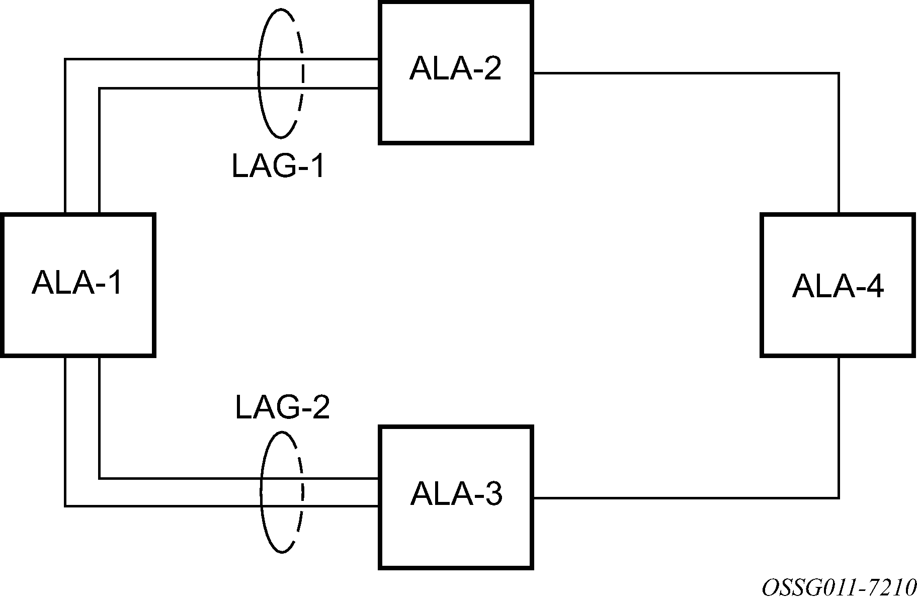
The following figure shows traffic routed between ALA-1 and ALA-2 as a LAG consisting of four ports.
LAG and QoS policies on 7210 SAS-D and 7210 SAS-Dxp
On the 7210 SAS-D and 7210 SAS-Dxp, an ingress QoS policy is applied to the aggregate traffic that is received on all the member ports of the LAG. For example, if an ingress policy is configured with a policer of PIR 100Mbps, for a SAP configured on a LAG with two ports, then the policer limits the traffic received through the two ports to a maximum of 100Mbps.
On the 7210 SAS-D and 7210 SAS-Dxp, an egress QoS policy parameters are applied to all the ports that are members of the LAG (all ports get the full SLA). For example, if an egress policy is configured with a queue shaper rate of PIR 100Mbps, and applied to an access-uplink or access LAG configured with two port members, then each port would send out 100 Mbps of traffic for a total of 200Mbps of traffic out of the LAG. The advantage of this method over a scheme where the PIR is divided equally among all the member ports of the LAG is that, a single flow can use the entire SLA. The disadvantage is that, the overall SLA can be exceeded if the flows span multiple ports.
LAG and QoS policies on 7210 SAS-K 2F1C2T, 7210 SAS-K 2F6C4T, and 7210 SAS-K 3SFP+ 8C
On the 7210 SAS-K 2F1C2T, 7210 SAS-K 2F6C4T, and 7210 SAS-K 3SFP+ 8C, an ingress QoS policy is applied to the aggregate traffic that is received through all the member ports of the LAG and mapped to that service entity (for example: access-uplink port). For example, if an ingress policy is configured with a queue shaper rate of PIR 100Mbps for an access-uplink LAG configured with two ports, then the queue shaper limits the traffic received through the two ports to a maximum of 100Mbps.
On the 7210 SAS-K 2F1C2T,7210 SAS-K 2F6C4T, and 7210 SAS-K 3SFP+ 8C, egress QoS policy parameters are applied to all the ports that are members of the LAG (all ports get the full SLA). For example, if an egress policy is configured with a queue shaper rate of PIR 100Mbps, and applied to an access-uplink LAG configured with two port members, then each port can send out 100 Mbps of traffic for a total of 200Mbps of traffic out of the LAG (assuming flows are distributed among the 2 ports). The advantage of this method over a scheme where the PIR is divided equally among all the member ports of the LAG is that a single flow can use the entire SLA. The disadvantage is that the overall SLA can be exceeded if the flows span multiple ports.
Port link damping
Hold time controls enable port link damping timers that reduce the number of link transitions reported to upper layer protocols.
The 7210 SAS port link damping feature guards against excessive port transitions. Any initial port transition is immediately advertised to upper layer protocols, but any subsequent port transitions are not advertised to upper layer protocols until a configured timer has expired.
An ‟up” timer controls the dampening timer for link up transitions, and a ‟down” timer controls the dampening timer for link down transitions.
LACP
Generally, link aggregation is used for two purposes: provide an increase in bandwidth and provide redundancy. Both aspects are addressed by aggregating several Ethernet links in a single LAG.
LACP enhancements allow active lag-member selection based on particular constrains. The mechanism is based on the IEEE 802.3ax standard so interoperability is ensured.
LAG and ECMP hashing
See the 7210 SAS-D, Dxp, K 2F1C2T, K 2F6C4T, K 3SFP+ 8C Router Configuration Guide for more information about ECMP support for 7210 SAS platforms.
When a requirement exists to increase the available bandwidth for a logical link that exceeds the physical bandwidth or add redundancy for a physical link, typically one of the following methods is applied:
equal cost multi-path (ECMP)
Link Aggregation (LAG)
A 7210 SAS can deploy both methods at the same time, meaning it can use ECMP of two or more Link Aggregation Groups (LAG) or single links.The Nokia implementation supports per flow hashing used to achieve uniform loadspreading and per service hashing designed to provide consistent per service forwarding. Depending on the type of traffic that needs to be distributed into an ECMP or a LAG, different variables are used as input to the hashing algorithm.
The following tables list the packets used for hashing on 7210 SAS platforms.
LAG hashing algorithm for the 7210 SAS-D
The following table describes the packet fields used for hashing for services configured on the 7210 SAS-D.
The following notes apply to LAG hashing algorithm for services configured on 7210 SAS-D:
The term ‟learned” corresponds to the Destination MAC.
the term ‟Source and Destination MAC” refers to customer source and destination MACs unless otherwise specified.
The VLAN ID is considered for learned PBB and non-IP traffic in the VPLS service only for traffic ingressing at dot1q, Q.*, Q1.Q2 SAPs.
Only the outer VLAN tag is used for hashing.
Traffic type |
Packet fields used |
||||||||
|---|---|---|---|---|---|---|---|---|---|
|
BDA |
BSA |
EtherType |
Ingress Port-ID |
ISID |
Source and destination |
VLAN |
|||
|
MAC |
IP |
L4 Ports |
|||||||
VPLS service SAP to SAP |
|||||||||
IP traffic (learned) |
✓ |
✓ |
|||||||
IP traffic (unlearned) |
✓ |
✓ |
✓ |
||||||
PBB traffic (learned) |
✓ |
✓ |
✓ |
||||||
PBB traffic (unlearned) |
✓ |
✓ |
✓ |
✓ |
|||||
Non-IP traffic (learned) |
✓ |
✓ |
✓ |
||||||
Non-IP traffic (unlearned) |
✓ |
✓ |
✓ |
✓ |
|||||
Epipe service SAP to SAP |
|||||||||
IP traffic |
✓ |
✓ |
✓ |
||||||
PBB traffic |
✓ |
✓ |
✓ |
✓ |
|||||
Non-IP traffic |
✓ |
✓ |
✓ |
✓ |
|||||
IES service (IPv4): IES SAP to IES SAP |
|||||||||
IPv4 unicast traffic |
✓ |
✓ |
|||||||
LAG hashing algorithm for the 7210 SAS-Dxp
The following table describes the packet fields used for hashing for services configured on the 7210 SAS-Dxp.
The following notes apply to LAG hashing algorithm for services configured on 7210 SAS-Dxp:
The term ‟learned” corresponds to the Destination MAC.
The term ‟Source and Destination MAC” refers to customer source and destination MACs unless otherwise specified.
The VLAN ID is considered for learned PBB and non-IP traffic in the VPLS service only for traffic ingressing at dot1q, Q.*, Q1.Q2 SAPs.
Only the outer VLAN tag is used for hashing.
Traffic type |
Packet fields used |
||||||||
|---|---|---|---|---|---|---|---|---|---|
|
BDA |
BSA |
EtherType |
Ingress Port-ID |
ISID |
Source and destination |
VLAN |
|||
|
MAC |
IP |
L4 Ports |
|||||||
VPLS service SAP to SAP |
|||||||||
IP traffic (learned) |
✓ |
✓ |
|||||||
IP traffic (unlearned) |
✓ |
✓ |
|||||||
PBB traffic (learned) |
✓ |
✓ |
|||||||
PBB traffic (unlearned) |
✓ |
✓ |
✓ |
||||||
Non-IP traffic (learned) |
✓ |
✓ |
|||||||
Non-IP traffic (unlearned) |
✓ |
✓ |
|||||||
Epipe service SAP to SAP |
|||||||||
IP traffic |
✓ |
✓ |
|||||||
PBB traffic |
✓ |
✓ |
✓ |
||||||
Non-IP traffic |
✓ |
✓ |
|||||||
IES service (IPv4): IES SAP to IES SAP |
|||||||||
IPv4 unicast traffic |
✓ |
✓ |
|||||||
LAG hashing algorithm for the 7210 SAS-K 2F1C2T
The following table describes the packet fields used for hashing for services configured on the 7210 SAS-K 2F1C2T.
The following notes apply to LAG hashing algorithm for services configured on 7210 SAS-K 2F1C2T:
The term ‟learned” corresponds to the Destination MAC.
The term ‟Source and Destination MAC” refers to customer source and destination MACs unless otherwise specified.
Traffic type |
Packet fields used |
||||||||
|---|---|---|---|---|---|---|---|---|---|
|
BDA |
BSA |
Ingress Port-ID |
IP Protocol |
Source and destination |
VLAN |
||||
|
MAC |
IP |
L4 Ports |
Outer |
Inner |
|||||
VPLS Service SAP to SAP |
|||||||||
IP traffic (learned and unlearned) |
✓ |
✓ |
✓ |
✓ |
✓ |
||||
PBB traffic (learned and unlearned) |
✓ |
✓ |
✓ |
✓ |
✓ |
||||
MPLS traffic (learned and unlearned) |
✓ |
✓ |
✓ |
✓ |
|||||
Non-IP traffic (learned and unlearned) |
✓ |
✓ |
✓ |
✓ |
|||||
Epipe Service SAP to SAP |
|||||||||
IP traffic |
✓ |
✓ |
✓ |
✓ |
✓ |
||||
PBB traffic |
✓ |
✓ |
✓ |
✓ |
✓ |
||||
MPLS traffic |
✓ |
✓1 |
✓ |
✓ |
|||||
Non-IP traffic |
✓ |
✓ |
✓ |
✓ |
|||||
LAG hashing algorithm for the 7210 SAS-K 2F6C4T and 7210 SAS-K 3SFP+ 8C
The following table describes the packet fields used for hashing for services configured on the 7210 SAS-K 2F6C4T and 7210 SAS-K 3SFP+ 8C.
The following notes apply to LAG hashing algorithm for services configured on 7210 SAS-K 2F6C4T and 7210 SAS-K 3SFP+ 8C:
The term ‟learned” corresponds to the destination MAC.
The term ‟Source and Destination MAC” refers to customer source an destination MACs unless otherwise specified.
SAP to SAP and SAP to SDP: Packet fields for IP traffic are used for hashing only if the number of VLAN tags is two or fewer. IP packets with more than two tags use the same hashing parameters as non-IP traffic.
SDP to SAP and SDP to SDP: Packet fields for IP traffic are used for hashing only if the number of VLAN tags is 1 or 0. IP packets with more than one tag use the same hashing parameters as non-IP traffic.
RVPLS routed traffic uses the same parameters as traffic in IES service.
For IPv6 packets, the source and destination IP addresses are XORed and collapsed into a 32-bit value.
Traffic type |
Packet fields used |
|||||||
|---|---|---|---|---|---|---|---|---|
|
Ingress Port-ID |
IP Protocol |
MPLS Label Stack |
Source and destination |
VLAN |
||||
|
MAC |
IP |
L4 Ports |
Outer |
Inner |
||||
VPLS Service SAP to SAP |
||||||||
IP traffic (learned and unlearned) |
✓ |
✓ |
✓ |
✓ |
✓ |
|||
MPLS traffic (learned and unlearned) |
✓ |
✓2 |
✓ |
✓ |
||||
Non-IP traffic (learned and unlearned) |
✓ |
✓ |
✓ |
✓ |
||||
VPLS Service SAP to SDP |
||||||||
IP traffic (learned and unlearned) |
✓ |
✓ |
✓ |
✓ |
✓ |
|||
MPLS traffic |
✓ |
✓2 |
✓ |
✓ |
||||
Non-IP traffic (learned and unlearned) |
✓ |
✓ |
✓ |
✓ |
||||
VPLS Service SDP to SAP3 |
||||||||
IP traffic (learned and unlearned) |
✓ |
✓ |
✓ |
✓ |
||||
Non-IP traffic (learned and unlearned) |
✓ |
✓ |
||||||
VPLS Service SDP to SDP3 |
||||||||
IP traffic (learned and unlearned) |
✓ |
✓ |
✓ |
✓ |
||||
Non-IP traffic (learned and unlearned) |
✓ |
✓ |
||||||
Epipe Service SAP to SAP |
||||||||
IP traffic |
✓ |
✓ |
✓ |
✓ |
✓ |
|||
MPLS traffic |
✓ |
✓2 |
✓ |
✓ |
||||
Non-IP traffic |
✓ |
✓ |
✓ |
✓ |
||||
Epipe Service SAP to SDP |
||||||||
IP traffic |
✓ |
✓ |
✓ |
✓ |
✓ |
|||
MPLS traffic |
✓ |
✓2 |
✓ |
✓ |
||||
Non-IP traffic |
✓ |
✓ |
✓ |
✓ |
||||
Epipe Service SDP to SAP3 |
||||||||
IP traffic (learned and unlearned) |
✓ |
✓ |
✓ |
✓ |
||||
Non-IP traffic (learned and unlearned) |
✓ |
✓ |
||||||
MPLS - LSR |
||||||||
All traffic |
✓ |
✓4 |
✓ |
|||||
IES Service (IPv4) IES SAP to IES SAP |
||||||||
— |
✓ |
✓ |
|
✓5 |
✓ |
✓ |
||
IES Service (IPv6) IES SAP to IES SAP |
||||||||
— |
✓ |
✓ |
|
✓5 |
✓ |
✓ |
||
IES Service (IPv4) IES SAP to IPv4 network port interface |
||||||||
— |
✓ |
✓ |
|
✓5 |
✓ |
✓ |
||
IES Service (IPv6) IES SAP to IPv6 network port interface |
||||||||
— |
✓ |
✓ |
|
✓5 |
✓ |
✓ |
||
IES Service (IPv4) interface IPv4 network port interface to IES SAP |
||||||||
— |
✓ |
✓ |
|
✓5 |
✓ |
✓ |
||
IES Service (IPv6) IPv6 network port interface to IES SAP |
||||||||
— |
✓ |
✓ |
|
✓5 |
✓ |
✓ |
||
Network port (IPv4) interface IPv4 network interface to IPv4 network interface |
||||||||
— |
✓ |
✓ |
|
✓5 |
✓ |
✓ |
||
Network port (IPv6) interface IPv6 network interface to IPv6 network interface |
||||||||
— |
✓ |
✓ |
|
✓5 |
✓ |
✓ |
||
VPRN SAP to SAP, SDP to SAP, SAP to SDP |
||||||||
— |
✓ |
✓ |
|
✓5 |
✓ |
✓ |
||
Packet fields used for pseudowire hash-label generation on the 7210 SAS-K 2F6C4T and 7210 SAS-K 3SFP+ 8C
The following table describes the packet fields used by different services and traffic types to generate the PW hash label.
Traffic type |
Packet fields used |
||||||
|---|---|---|---|---|---|---|---|
|
Ingress Port-ID |
IP Protocol |
Source and destination |
VLAN |
||||
|
MAC |
IP |
L4 Ports |
Outer |
Inner |
|||
VPLS and Epipes services SAP to SDP |
|||||||
IP traffic (learned and unlearned) |
✓ |
✓ |
✓ |
✓ |
✓ |
||
MPLS traffic (learned and unlearned) |
✓ |
✓6 |
✓ |
✓ |
|||
Non-IP traffic (learned and unlearned) |
✓ |
✓ |
✓ |
✓ |
|||
VPLS services SDP to SDP |
|||||||
IP traffic (learned and unlearned) |
✓ |
✓ |
✓ |
✓ |
|||
Non-IP traffic (learned and unlearned) |
✓ |
✓ |
|||||
LDP ECMP hashing algorithm for the 7210 SAS-K 2F6C4T and 7210 SAS-K 3SFP+ 8C
The following table describes the packet fields used for LDP ECMP hashing for label edge router (LER) and label switching router (LSR) devices on the 7210 SAS-K 2F6C4T and 7210 SAS-K 3SFP+ 8C.
Traffic type |
Packet fields used |
|||||||
|---|---|---|---|---|---|---|---|---|
|
Ingress Port-ID |
IP Protocol |
MPLS Label Stack |
Source and destination |
VLAN |
||||
|
MAC |
IP |
L4 Ports |
Outer |
Inner |
||||
VPLS and Epipe services SAP to SDP (iLER) |
||||||||
IP traffic |
✓ |
✓ |
✓ |
✓ |
✓ |
|||
MPLS traffic |
✓ |
✓7 |
✓ |
✓ |
||||
Non-IP traffic |
✓ |
✓ |
✓ |
✓ |
||||
LSR |
||||||||
MPLS traffic |
✓ |
✓8 |
✓ |
|||||
Multi-Chassis LAG
This section describes the Multi-Chassis LAG (MC-LAG) concept. MC-LAG is an extension of a LAG concept that provides node-level redundancy in addition to link-level redundancy provided by ‟regular LAG”.
MC-LAG is supported on the 7210 SAS-K 2F6C4T and 7210 SAS-K 3SFP+ 8C.
Typically, MC-LAG is deployed in a network-wide scenario and provides redundant connection between different end points. The whole scenario is then built by a combination of different mechanisms (for example, MC-LAG and redundant pseudowire to provide end-to-end (e2e) redundant point-to-point (p2p) connection or dual homing of CPE devices in Layer 2/3 VPNs).
Overview
MC-LAG is a method of providing redundant Layer 2/3 access connectivity that extends beyond link level protection by allowing two systems to share a common LAG end point.
The CPE/access node is connected with multiple links toward a redundant pair of Layer 2/3 access aggregation nodes such that both link and node level redundancy is provided. By using a multi-chassis LAG protocol, the paired Layer 2/3 aggregation nodes (referred to as the redundant-pair) appear to be a single node that is utilizing LACP toward the access node. The multi-chassis LAG protocol between the redundant-pair ensures a synchronized forwarding plane to and from the CPE/access node. It is used to synchronize the link state information between the redundant-pair nodes and provide correct LACP messaging to the CPE/access node from both redundant-pair nodes.
To ensure SLAs and deterministic forwarding characteristics between the CPE/access and the redundant-pair node, the multi-chassis LAG function provides an active/standby operation toward/from the CPE/access node. LACP is used to manage the available LAG links into active and standby states so that only links from one aggregation node are active at a time to and from the CPE/access node.
MC-LAG has the following characteristics:
Selection of the common system ID, system-priority, and administrative-key are used in LACP messages to ensure that partner systems consider all links part of the same LAG.
The selection algorithm is extended to allow the selection of the active subgroup.
The subgroup definition in the LAG context is still local to the single box. Consequently, even when subgroups configured on two different systems have the same subgroup-id, they are still considered two separate subgroups within the specific LAG.
The configuration of multiple subgroups per PE in an MC-LAG is supported.
If there is a tie in the selection algorithm, for example, two subgroups with identical aggregate weight (or number of active links), the group that is local to the system with lower system LACP priority and LAG system ID is selected.
Providing an inter-chassis communication channel allows the inter-chassis communication to support LACP on both systems. The communication channel enables the following functionality:
It supports connections at the IP level that do not require a direct link between two nodes. The IP address configured at the neighbor system is one of the addresses of the system (interface or loop-back IP address).
The communication protocol provides heartbeat mechanism to enhance robustness of the MC-LAG operation and detect node failures.
It supports operator actions that force an operational change on nodes.
The LAG group-ids do not have to match between neighbor systems. At the same time, multiple LAG groups between the same pair of neighbors is also allowed.
It verifies that the physical characteristics, such as speed and auto-negotiation are configured and initiates operator notifications (traps) if errors exist. Consistency of MC-LAG configuration (system-id, administrative-key and system-priority) is provided. Load-balancing must be consistently configured on both nodes.
Traffic over the signaling link is encrypted using a user-configurable message digest key.
The MC-LAG function provides active/standby status to other software applications to build reliable solutions.
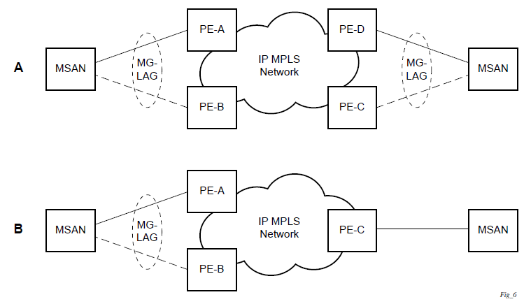
MC-LAG L2 dual homing to remote PE pairs and MC-LAG L2 dual homing to local PE-pairs show different combinations of supported MC-LAG attachments. The supported configurations can be divided into the following subgroups:
dual-homing to remote PE pairs
both end-points attached with MC-LAG
one end-point attached
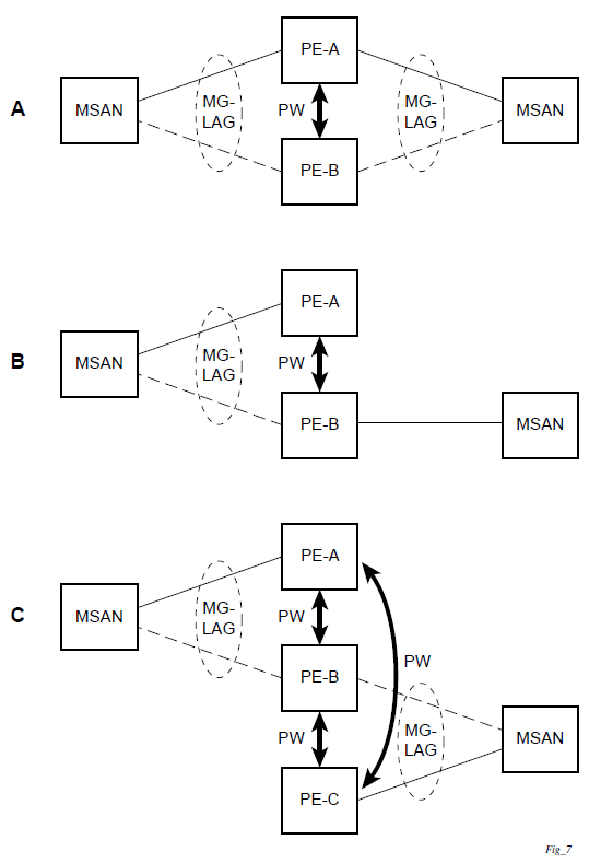
dual-homing to local PE pair
both end-points attached with MC-LAG
one end-point attached with MC-LAG
both end-points attached with MC-LAG to two overlapping pairs
The following figure shows dual homing to remote PE pairs.
The following figure shows dual homing to local PE pairs.
The forwarding behavior of the nodes is governed by the following principles. Note that the logical destination (actual forwarding decision) is primarily determined by the service (VPLS or VLL), and the following principle apply only if the destination or source is based on MC-LAG.
Packets received from the network will be forwarded to all local active links of the specific destination-sap based on conversation hashing. If there are no local active links, the packets will be cross-connected to the inter-chassis pseudowire.
Packets received from the MC-LAG sap will be forwarded to the active destination pseudowire or active local links of destination-sap. If no such objects are available at the local node, the packets will be cross-connected to inter-chassis pseudowire.
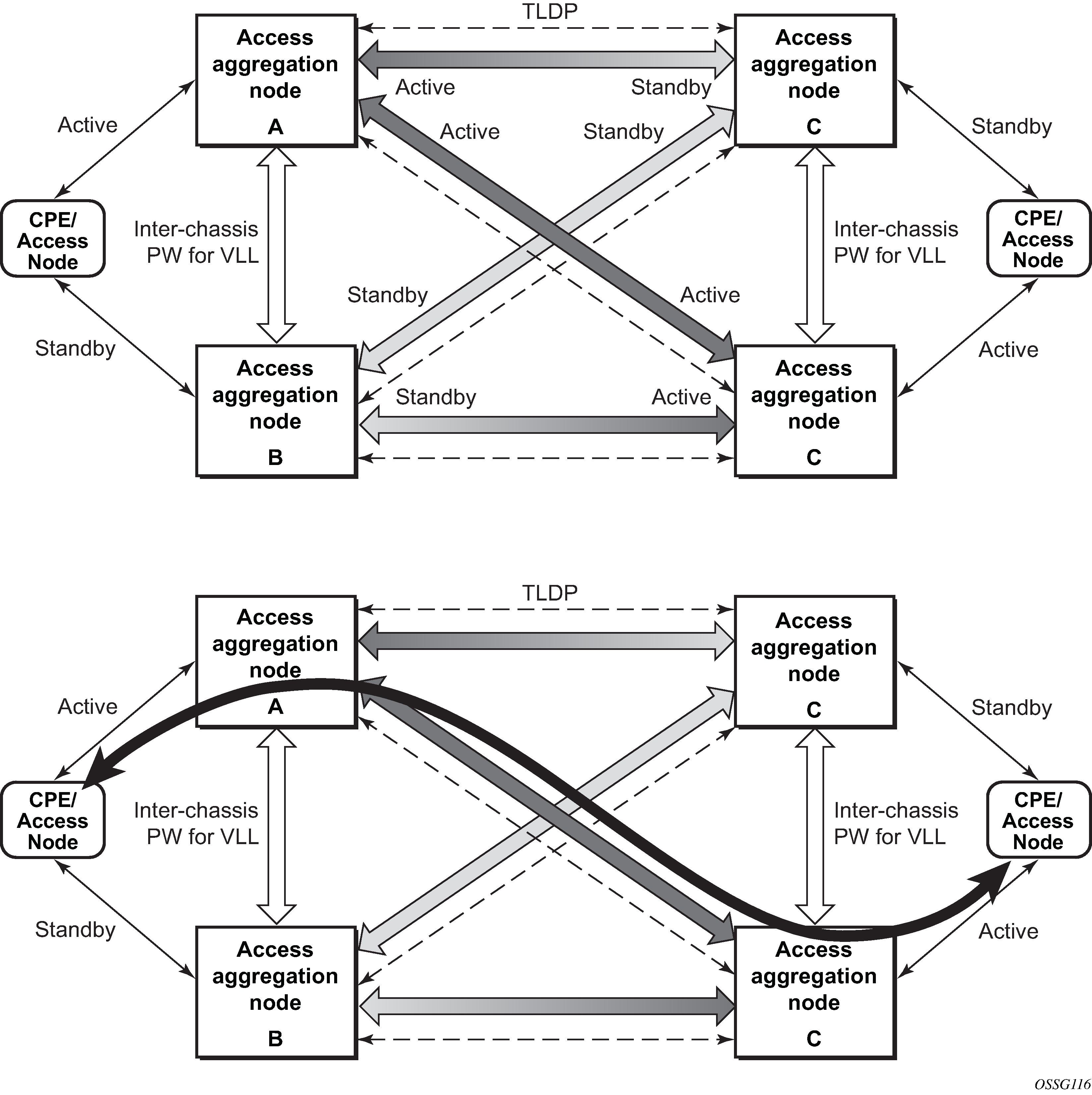
Point-to-point redundant connection across Layer 2/3 VPN network
The following figure shows the connection between two CPE/access nodes across network based on Layer 2/3 VPN pseudowires. The connection between a CPE/access node and a pair of access aggregation PE routers is realized by MC-LAG. From the CPE/access node perspective, a redundant pair of access aggregation PE routers acts as a single partner in LACP negotiation. At any point in time, only one of the routers has active links in a specific LAG. The status of LAG links is reflected in the status signaling of pseudowires set between all participating PEs. The combination of active and standby states across LAG links and pseudowires give only one unique path between a pair of MSANs.
Note that the configuration in the following figure shows an example configuration of VLL connections based on MC-LAG. Specifically, it shows a VLL connection where the two ends (SAPs) are located on two different redundant-pairs. However, additional configurations are possible, for example:
both ends of the same VLL connections are local to the same redundant-pair
one end of the VLL endpoint is on a redundant-pair and the other on a single (local or remote) node
Configuration guidelines
The following guidelines apply to MC-LAG configurations:
MC-LAG peer nodes must be of the same platform type. For example, 7210 SAS-K 2F6C4T can only peer with another 7210 SAS-K 2F6C4T, and 7210 SAS-K 3SFP+ 8C can only peer with another 7210 SAS-K 3SFP+ 8C. 7210 SAS-K 2F6C4T cannot be configured with 7210 SAS-K 3SFP+ 8C as its MC-LAG peer.
MC-LAG is only supported when using MPLS uplinks with network ports. It is not supported with access-uplink ports.
The 7210 SAS-K 2F6C4T and 7210 SAS-K 3SFP+ 8C can also be MC-LAG clients, with an active/standby LAG configuration used to dual-home to access-aggregation routers when using access-uplink ports. In this scenario the user has an option to provision the uplinks as access-uplink ports to dual-home into two aggregation PE routers that are configured as MC-LAG peers.
Configuring multi-chassis redundancy
When configuring associated LAG ID parameters, the LAG must be in access mode and LACP must be enabled.
Use the following syntax to configure multi-chassis redundancy features.
config>redundancy
  multi-chassis
     peer ip-address
        authentication-key [authentication-key | hash-key][hash | hash2]
        description description-string
        mc-lag
           hold-on-neighbor-failure duration
           keep-alive-interval interval
           lag lag-id lacp-key admin-key system-id system-id [remotelag lag-
id] system-priority system-priority
           no shutdown
        no shutdown
        source-address ip-address
        sync
           igmp-snooping
           port [port-id | lag-id] [sync-tag]range encap-range sync-tag
           no shutdown
config>redundancy# multi-chassis
config>redundancy>multi-chassis# peer 10.10.10.2 create
config>redundancy>multi-chassis>peer# description "Mc-Lag peer 10.10.10.2"
config>redundancy>multi-chassis>peer# mc-lag
config>redundancy>mc>peer>mc-lag# lag 1 lacp-key 32666 system-
id 00:00:00:33:33:33 system-priority 32888
config>redundancy>mc>peer>mc-lag# no shutdown
config>redundancy>mc>peer>mc-lag# exit
config>redundancy>multi-chassis>peer# no shutdown
config>redundancy>multi-chassis>peer# exit
config>redundancy>multi-chassis# exit
config>redundancy#
The following is a sample configuration output.
*7210-SAS>config>redundancy# info
----------------------------------------------
        multi-chassis
            peer 1.1.1.1 create
                shutdown
                sync
                    shutdown
                    port 1/1/1 create
                    exit
                exit
            peer 10.20.1.3 create
                mc-lag
                    lag 3 lacp-key 1 system-id 00:00:00:aa:bb:cc remote-
lag 1 system-priority 1
                    no shutdown
                exit
                no shutdown
            exit
        exit
----------------------------------------------
*7210-SAS>config>redundancy#
MC-LAG support on 7210 SAS-D and 7210 SAS-K 2F1C2T
Multi-Chassis LAG (MC-LAG) is an extension of a LAG concept that provides node-level redundancy in addition to the link-level redundancy provided by ‟regular LAG”. Typically, MC-LAG is deployed network-wide, along with IP/MPLS, providing redundant connections between different access end points. In a typical MC-LAG deployment, a pair of nodes are configured to be MC-LAG peers (also referred to as MC-LAG servers), and access devices are connected to the MC-LAG peers using LAGs with active/standby LAG groups.
The 7210 SAS-D, 7210 SAS-K 2F1C2T, 7210 SAS-K 2F6C4T, and 7210 SAS-K 3SFP+ 8C platforms can be connected to an MC-LAG-enabled node, such as an MC-LAG server. In particular, these platforms allow for provisioning of links into subgroups in a LAG and support active/standby links. The MC-LAG solution can be achieved with or without subgroups configured.
G.8032 protected Ethernet rings
Ethernet ring protection switching provides ITU-T G.8032 specification compliance to achieve resiliency for Ethernet Layer 2 networks. G.8032 (Eth-ring) is built on Ethernet OAM and is often referred to as Ring Automatic Protection Switching (R-APS).
See ‟G.8032 Protected Ethernet Rings” in the 7210 SAS-D, Dxp, K 2F1C2T, K 2F6C4T, K 3SFP+ 8C Services Guide for more information about Ethernet rings.
802.1x network access control
The Nokia 7210 SAS supports network access control of client devices (PCs, STBs, and so on) on an Ethernet network using the IEEE. 802.1x standard. 802.1x is known as Extensible Authentication Protocol (EAP) over a LAN network or EAPOL.
802.1x modes
The 7210 SAS supports port-based network access control for Ethernet ports only. Every Ethernet port can be configured to operate in one of three different operation modes, controlled by the port-control parameter:
force-auth
Disables 802.1x authentication and causes the port to transition to the authorized state without requiring any authentication exchange. The port transmits and receives normal traffic without requiring 802.1x-based host authentication. This is the default setting.
force-unauth
Causes the port to remain in the unauthorized state, ignoring all attempts by the hosts to authenticate. The switch cannot provide authentication services to the host through the interface.
auto
Enables 802.1x authentication. The port starts in the unauthorized state, allowing only EAPOL frames to be sent and received through the port. Both the router and the host can initiate an authentication procedure that is described as follows. The port will remain in an unauthorized state (no traffic except EAPOL frames is allowed) until the first client is authenticated successfully. After this, traffic is allowed on the port for all connected hosts.
802.1x basics
The supplicant — This is the end-user device that requests access to the network.
The authenticator — Controls access to the network. Both the supplicant and the authenticator are referred to as PAEs.
The authentication server — Performs the actual processing of the user information.
The authentication exchange is carried out between the supplicant and the authentication server, the authenticator acts only as a bridge. The communication between the supplicant and the authenticator is done through the Extended Authentication Protocol (EAP) over LANs (EAPOL). On the back end, the communication between the authenticator and the authentication server is done with the RADIUS protocol. The authenticator is therefore a RADIUS client, and the authentication server a RADIUS server.
The router initiates the procedure when the Ethernet port becomes operationally up, by sending a special PDU called EAP-Request/ID to the client. The client can also initiate the exchange by sending an EAPOL-start PDU, if it does not receive the EAP-Request/ID frame during bootup. The client responds on the EAP-Request/ID with a EAP-Response/ID frame, containing its identity (typically username + password).
After receiving the EAP-Response/ID frame, the router will encapsulate the identity information into a RADIUS AccessRequest packet, and send it off to the configured RADIUS server.
The RADIUS server checks the supplied credentials, and if approved will return an Access Accept message to the router. The router notifies the client with an EAP-Success PDU and puts the port in authorized state.
802.1x timers
The 802.1x authentication procedure is controlled by a number of configurable timers and scalars. There are two separate sets, one for the EAPOL message exchange and one for the RADIUS message exchange.
EAPOL timers:
transit-period
Indicates how many seconds the Authenticator will listen for an EAP-Response/ID frame. If the timer expires, a new EAP-Request/ID frame will be sent and the timer restarted. The default value is 60. The range is 1 to 3600 seconds.
supplicant-timeout
This timer is started at the beginning of a new authentication procedure (transmission of first EAP-Request/ID frame). If the timer expires before an EAP-Response/ID frame is received, the 802.1x authentication session is considered as having failed. The default value is 30. The range is 1 to 300.
quiet-period
Indicates number of seconds between authentication sessions. It is started after logout, after sending an EAP-Failure message or after expiry of the supplicant-timeout timer. The default value is 60. The range is 1 to 3600.
RADIUS timer and scaler:
max-auth-req
Indicates the maximum number of times that the router will send an authentication request to the RADIUS server before the procedure is considered as having failed. The default value is value 2. The range is 1 to 10.
server-timeout
Indicates how many seconds the authenticator will wait for a RADIUS response message. If the timer expires, the access request message is sent again, up to max-auth-req times. The default value is 60. The range is 1 to 3600 seconds.
The router can also be configured to periodically trigger the authentication procedure automatically. This is controlled by the enable re-authentication and reauth-period parameters. Reauth-period indicates the period in seconds (since the last time that the authorization state was confirmed) before a new authentication procedure is started. The range of reauth-period is 1 to 9000 seconds (the default is 3600 seconds, one hour). Note that the port stays in an authorized state during the re-authentication procedure.
802.1x configuration and limitations
Configuration of 802.1x network access control on the router consists of two parts:
Generic parameters, which are configured under config>security>dot1x
Port-specific parameters, which are configured under config>port>ethernet>dot1x
801.x authentication:
Provides access to the port for any device, even if only a single client has been authenticated.
Can only be used to gain access to a predefined Service Access Point (SAP). It is not possible to dynamically select a service (such as a VPLS service) depending on the 802.1x authentication information.
802.1x tunneling for Epipe service
Customers who subscribe to Epipe service considers the Epipe as a wire, and run 802.1x between their devices which are located at each end of the Epipe.
This feature applies only to port-based Epipe SAPs because 802.1x runs at the port level not the VLAN level. Therefore such ports must be configured as null encapsulated SAPs.
When 802.1x tunneling is enabled, the 802.1x messages received at one end of an Epipe are forwarded through the Epipe. When 802.1x tunneling is disabled (by default), 802.1x messages are dropped or processed locally according to the 802.1x configuration (shutdown or no shutdown).
Enabling 802.1x tunneling requires the 802.1x mode to be set to force-auth. Enforcement is performed at the CLI level.