Ports
This section describes 7210 SAS ports.
Port types
The following table lists supported Ethernet port types on the 7210 SAS platforms.
Port modes
On 7210 SAS devices, a port must be configured as one of the following: access, access uplink, network, or hybrid. The following list describes the significance of the different port modes and the support available on different platforms:
access ports
Access ports are configured for customer-facing traffic on which services are configured. If a Service Access Port (SAP) is to be configured on the port, it must be configured as an access port. When a port is configured for access mode, the appropriate encapsulation type must be configured to distinguish the services on the port. When a port has been configured for access mode, one or more services can be configured on the port depending on the encapsulation value.
access-uplink ports
Access-uplink ports are used to provide native Ethernet connectivity in service provider transport or infrastructure network. This can be achieved by configuring port mode as access uplink. With this option, the encap-type can be configured to QinQ only. Access-uplink SAPs, which are QinQ SAPs, can only be configured on an access uplink port to allow the operator to differentiate multiple services being carried over a single access uplink port.
network ports (applicable only to the 7210 SAS-K 2F6C4T and 7210 SAS-K 3SFP+ 8C)
Network ports are configured for network-facing traffic. These ports participate in the service provider transport or infrastructure network. Dot1q is supported on network ports.
hybrid ports (applicable only to the 7210 SAS-K 2F6C4T and 7210 SAS-K 3SFP+ 8C)
Hybrid ports are configured for access and network-facing traffic. The default mode of an Ethernet port is ‟network”. The mode of a port cannot be changed unless the port is shut down and the configured SAPs and interfaces are deleted. Hybrid ports allow a single port to operate in both access and network modes. The MTU of a port in hybrid mode is the same as in network mode. The default encapsulation for ports in hybrid mode is dot1q; QinQ encapsulation is also supported at the port level.
When the port is changed to hybrid, the default MTU of the port is changed to match the value of 9212 bytes, which is used in network mode (higher than in access mode); this ensures that both SAP and network VLANs can be accommodated.
The only exception is when the port is a 10/100 fast Ethernet port. In this case, the MTU in hybrid mode is set to 1522 bytes, which corresponds to the default access MTU with QinQ, which is larger than the network dot1q MTU or access dot1q MTU for this type of Ethernet port. All parameters in access and network contexts are configured within the port using the same CLI hierarchy as in the existing implementation. A hybrid port allows both ingress and egress contexts to be configured concurrently.
An Ethernet port configured in hybrid mode can have the following encapsulation type values: dot1q and QinQ. The NULL value is not supported because only a single SAP or network IP interface is allowed, achieved by configuring the port as either access or network, respectively. Hybrid mode can be enabled on a LAG port when the port is part of a single chassis LAG configuration. When the port is part of a multi-chassis LAG (MC-LAG) configuration, only access mode can be configured. MC-LAG is not supported on network ports and consequently cannot be supported on hybrid ports.
The following table describes supported port modes on the 7210 SAS platforms.
Port mode platforms |
Access |
Network |
Hybrid |
Access-uplink |
|---|---|---|---|---|
7210 SAS-D |
Yes |
No |
No |
Yes |
7210 SAS-Dxp |
Yes |
No |
No |
Yes3 |
7210 SAS-K 2F1C2T |
Yes |
No |
No |
Yes |
7210 SAS-K 2F6C4T |
Yes |
Yes |
Yes |
Yes |
7210 SAS-K 3SFP+ 8C |
Yes |
Yes |
Yes |
Yes |
Port dot1q VLAN Etype on 7210 SAS-D, 7210 SAS-Dxp, 7210 SAS-K 2F1C2T, 7210 SAS-K 2F6C4T, and 7210 SAS-K 3SFP+ 8C
The 7210 SAS supports an option to allow the user to use a different dot1q VLAN Ethernet Type (Etype). It allows for interoperability with third-party switches that use some non-standard (other than 0x8100) dot1q VLAN Etype.
Configuration guidelines for dot1q-Etype for 7210 SAS-D and 7210 SAS-Dxp
The following are the configuration guidelines for Dot1q-Etype configured for dot1q encap port on 7210 SAS-D and 7210 SAS-Dxp:
Dot1q-Etype configuration is supported for all ports - Access and Access-uplink ports.
Dot1q-preserve SAPs cannot be configured on dot1q encap ports configured to use ether type other than 0x8100.
Priority tagged packet received with Etype 0x8100 on a dot1q port configured with Etype 0x9100 are classified as priority tagged packet and mapped to a dot1q :0 SAP (if configured) and the priority tag is removed.
Priority tagged packets received with Etype 0x6666 (any value other than 0x8100) on a dot1q port configured with Etype 0x9100 is classified as null-tagged packet and mapped to a dot1q :0 SAP (if configured) and the priority tag is retained and forwarded.
The dot1q-Etype is modified only for the dot1q encap access port.
Support for power over Ethernet
Power over Ethernet (PoE) is supported only on the 7210 SAS-Dxp 16p and 7210 SAS-Dxp 24p.
The 7210 SAS-Dxp 16p and 7210 SAS-Dxp 24p support PoE in accordance with the 802.3af, 802.3at, and 802.3bt standards. This feature allows these platforms to supply power to connected PoE devices, such as telephones, CCTV cameras, and other PoE standard compliant devices.
The following PoE functionalities are available:
The 7210 SAS-Dxp 16p and 7210 SAS-Dxp 24p support 802.3af (PoE), 802.3at (PoE+), and 802.bt (PoE++ and HPoE). All ports support PoE and PoE+. only the first four copper ports support PoE++ and HPoE. The ports can be used to connect PoE, PoE+, PoE++, or HPoE devices, or a combination of both simultaneously, as long as the power drawn is within the device system limits.
Only Alternative A, as described in the 802.3af and 802.3at standards, is supported on the 7210 SAS.
The 7210 SAS-Dxp 16p and 7210 SAS-Dxp 24p support classification Type 1, Type 2, Type 3, and Type 4 PoE devices (PDs) using the physical layer classification mechanism. The physical layer classification mechanism supports both the single-signature and dual-signature classification mechanisms.
The user must configure the maximum available PoE power budget using the configure system poe max-poe-power-budget command before enabling PoE on any of the ports. See the 7210 SAS-D, Dxp, K 2F1C2T, K 2F6C4T, K 3SFP+ 8C Basic System Configuration Guide for more information about this command.
The 7210 SAS-Dxp 16p and 7210 SAS-Dxp 24p support the PoE type and class-based power allocation method, which allocates power based on the identified PoE type and class using a physical layer classification mechanism. The 802.3af, 802.3at, and 802.3bt standards define four PoE types (Type 1 (up to 15W, Type 2 (up to 30 W), Type 3 (up to 60W), and Type 4 (up to 90 W)) and the power that can be allocated or requested by a particular class. The standards define eight classes: Class 1, Class 2, Class 3, Class 4, Class 5, Class 6, Class 7, and Class 8. These classes are used to allow PoE devices to request power based on their needs. If there is not enough power available to supply the identified class, power is denied to the connected PoE device. Each 7210 SAS device has a limit on the maximum amount of power it can provide. If the total power requested by the PDs connected to PoE-enabled ports exceeds this threshold, the 7210 SAS device denies power to the other PD. When power is denied to the PD, the port is operationally up, even though power is not supplied to the port. If power is applied successfully or denied to the port, the system logs an event.
Note:The software accounts for power requirements based on the PD type and does not consider the PoE class within a type (a PoE device uses 15 W, a PoE+ device uses 30 W, a PoE++ device uses 60 W, and a HPoE device uses 90 W).
For example, if the user configures one PoE port, the software deducts 15 W from the configured max-poe-power-budget. If the user configures two PoE ports and two PoE + ports, the software deducts 90 W from the configured max-poe-power-budget (assuming the configured value is greater than or equal to 90 W). If the user configures a value of 100 W and attempts to configure four PoE+ ports, the software deducts 30 W from the configured max-poe-power-budget for the first three configured PoE+ ports using a total of 90 W (10 W are remaining). When the user configures the fourth port, the configuration fails because only 10 W are available, which does not meet the power requirement for the fourth PoE+ port.
Only DC power is supplied to connected PDs. It is supported for PDs that use injectors where an AC/DC wall device is used to power a remote PoE device.
The software monitors the PoE port, detects faults and events, and raises traps. The software displays this information in the status report. The following events and faults are detected and are notified to the user:
supplying power event
This event is generated when power is supplied to a connected PoE device after successful detection and classification.
denied power event
This event is generated when power is denied to a connected PoE device after successful detection and classification.
disconnect event
This event is generated when a connected PoE device is disconnected from the port and stops drawing power from the node.
fault events
These events are generated for overload, short-circuit, and other events. Software clears the fault when the fault no longer exists.
If a port enabled for PoE is shut down, the power supplied to the port is disabled. It restores power when the no shutdown command is executed, if the request does not exceed the power budget.
PoE configuration notes
The following configuration notes apply for PoE:
On the 7210 SAS-Dxp 16p and 7210 SAS-Dxp 24p, all ports are available to connect PoE and PoE+ devices, and up to four fixed copper ports are available to connect PoE++ and HPoE devices.
The 7210 SAS-Dxp 16p and 7210 SAS-Dxp 24p can be equipped with the following external power module types to support required PoE devices:
100 W AC
290 W DC
480 W AC
960 W AC
The user can configure the maximum power budget for PoE devices using the config>system>poe>max-poe-power-budget command. See the 7210 SAS-D, Dxp, K 2F1C2T, K 2F6C4T, K 3SFP+ 8C Basic System Configuration Guide for more information about this command.
MACsec
- Media Access Control Security (MACsec) is supported only on the 7210 SAS-K 2F6C4T ETR, 7210 SAS-K 3SFP+ 8C, and 7210 SAS-Dxp 24p.
- On the 7210 SAS-Dxp 24p, MACsec is available on four ports:
- 1 GE SFP ports 1/1/19 and 1/1/20
- 1/10 GE SFP+ ports 1/1/17 and 1/1/18
MACsec is a security technology that provides secure communication for almost all types of traffic on Ethernet links. MACsec provides point-to-point and point-to-multipoint security on Ethernet links between directly connected nodes, or nodes connected using a Layer 2 cloud.
MACsec can identify and prevent most security threats, including:
denial of service
intrusion
man-in-the-middle
masquerading
passive wiretapping
playback attacks
MACsec, defined in IEEE 802.1AE, uses Layer 2 to encrypt MACsec to encrypt anything from the 802.1AE header to the end of the payload, including 802.1Q. MACsec leaves the DMAC and SMAC in cleartext.
The following figure shows the 802.1AE LAN-mode structure.
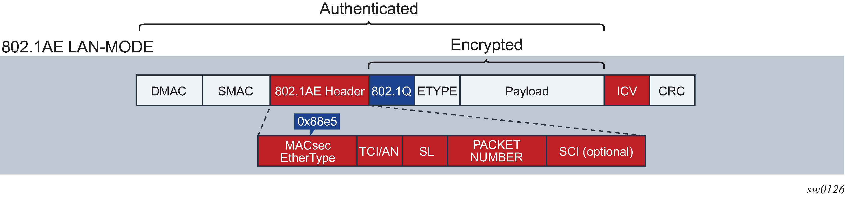
Forwarding a MACsec packet uses the destination MAC address, which is in cleartext.
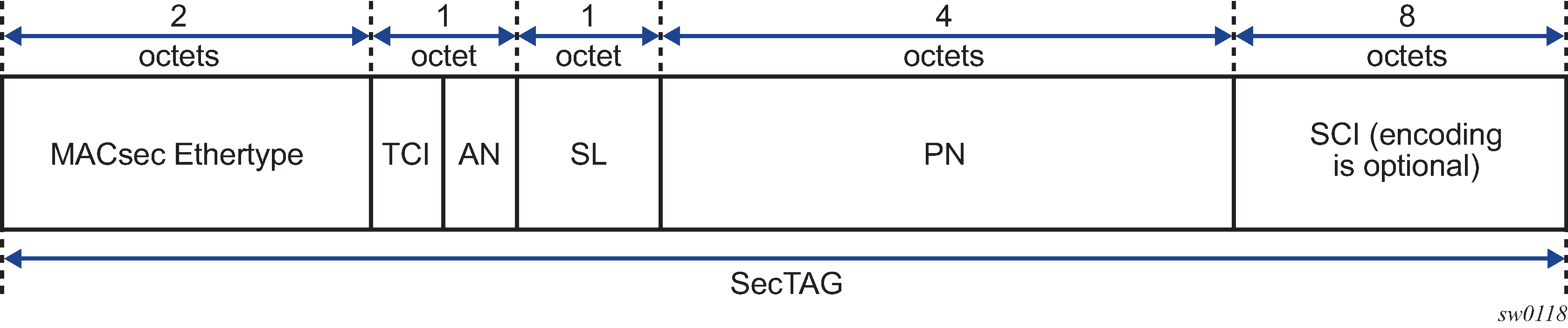
MACsec 802.1AE header (SecTAG)
The 802.1AE header has a security tag (SecTAG) which includes:
the association number within the channel
the packet number to provide a unique initialization vector for encryption and authentication algorithms, as well as protection against replay attack
an optional LAN-wide secure channel identifier
The SecTAG is identified by the MACsec Ethertype and includes the following fields:
TAG Control Information (TCI)
Association Number (AN)
Short Length (SL)
Packet Number (PN)
Optionally-encoded Secure Channel Identifier (SCI)
The following figure shows the format of the SecTAG.
MACsec encryption mode
MACsec uses the following main modes of encryption:
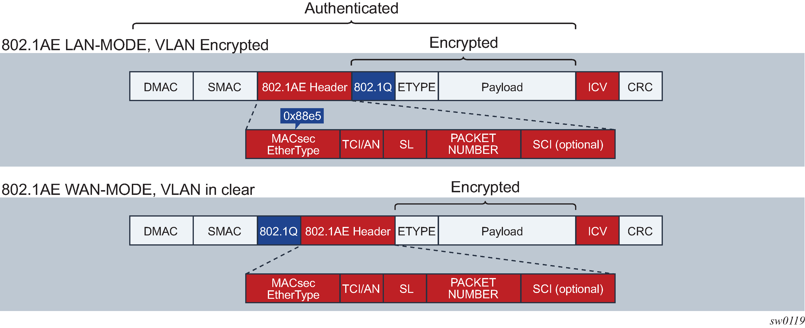
VLAN in cleartext (WAN Mode)
VLAN encrypted
The 802.1AE standard requires that the 802.1Q VLAN is encrypted. Some vendors provide the option of configuring MACsec on a port with VLAN in cleartext form. The 7210 SAS-K 2F6C4T, 7210 SAS-K 3SFP+ 8C, and 7210 SAS-Dxp 24p support both modes on both 1GE and 10GE ports.
The following figure shows VLAN in encrypted and cleartext form.
MACsec encryption per traffic flow encapsulation matching
MACsec can be applied to a selected subset of the port traffic based on the type and value of the packet encapsulation. The user can configure the system to match and encrypt all encapsulated traffic arriving on a port, including untagged, single-tagged, and double-tagged. This is the default behavior of MACsec and the only option supported.
MKA PDUs are generated specifically for the matched traffic encapsulation type.
MACsec terminology
The following table describes MACsec terminology.
MACsec term |
Description |
|---|---|
Connectivity Association (CA) |
A security relationship, established and maintained by the MKA, that comprises a fully connected subset of the service access points in stations attached to a single LAN that are to be supported by MACsec. |
MACsec Key Agreement Protocol (MKA) |
Control protocol between MACsec peers, which is used for peer aliveness and encryption key distribution. MKA is responsible for discovering, authenticating, and authorizing the potential participants in a CA. |
MAC Security Entity (SecY) |
Operates the MAC security protocol within a system. Manages and identifies the SC and the corresponding active SA. |
Port Access Entity (PAE) |
The protocol entity associated with a port. May support the functionality of authenticator, supplicant, or both. |
Security Channel (SC) |
Provides a unidirectional point-to-point or point-to-multipoint communication. Each SC contains a succession of SAs, and each SC has a different SAK. |
Security Association Key (SAK) |
The key used to encrypt the datapath of MACsec. |
Security Association (SA) |
A security relationship that provides security guarantees for frames transmitted from one member of a CA to the others. In the case of two SAs per SC, each with a different SAK, each SC comprises a succession of SAs. Each SA has an SC identifier, concatenated with a two-bit association number. The Secure Association Identifier (SAI) that has been created allows the receiving SecY to identify the SA, and consequently, the SAK used to decrypt and authenticate the received frame. The AN (and the SAI) is only unique for the SAs that can be used or recorded by participating SecYs at any time. The MKA creates and distributes SAKs to each of the SecYs in a CA. This key creation and distribution is independent of the cryptographic operation of each of the SecYs. The decision to replace one SA with its successor is made by the SecY that transmits using the SC, after the MKA has informed it that all the other SecYs are prepared to receive using that SA. No notification, other than receipt of a secured frame with a different SAI, is sent to the receiver. A SecY must always be capable of storing SAKs for two SAs for each inbound SC, and of swapping from one SA to another without notice. Certain LAN technologies can reorder frames of different priority, so reception of frames on a single SC can use interleaved SA. |
MACsec key management modes
The following table describes the key management modes in MACsec.
Keying |
Explanation |
SR OS support |
Where used |
|---|---|---|---|
Static Secure Association Key (SAK) |
Manually configures each node with a static SAK using CLI or NSP. |
N/A |
Switch to switch |
Static Connectivity Association Key (CAK) preshared key |
Uses dynamic MACsec Key Agreement (MKA) and uses a configured pre-shared key to derive the CAK. The CAK encrypts the SAK between two peers and authenticates the peers. |
Supported |
Switch to switch |
Dynamic CAK EAP Authentication |
Uses dynamic MKA and an EAP Master System Key (MSK) to derive the CAK. The CAK encrypts the SAK between two peers and authenticates the peers. |
Not Supported |
Switch to switch |
Dynamic CAK MSK Distribution via RADIUS and EAP-TLS |
MSKs are stored in the RADIUS server and distributed to the hosts via EAP-TLS. This is typically used in access networks where there are a large number of hosts using MACsec and connecting to an access switch. MKA uses MSK to derive the CAK. The CAK encrypts the SAK between 2 peers and authenticates the peers. |
Not Supported |
Host to switch |
MACsec static CAK
The following figure shows the main MACsec concepts used in the static CAK scenario.
MACsec uses SAs to encrypt packets. Each SA has a single SAK that contains the cryptographic operations used to encrypt the datapath PDUs.
The SAK is the secret key used by an SA to encrypt the channel.
When enabled, MACsec uses a static CAK security mode, which has two security keys: a CAK that secures control plane traffic and a randomly generated SAK that secures data plane traffic. Both keys are used to secure the point-to-point or point-to-multipoint Ethernet link and are regularly exchanged between devices on each end of the Ethernet link.
The following figure shows MACsec generating the CAK.
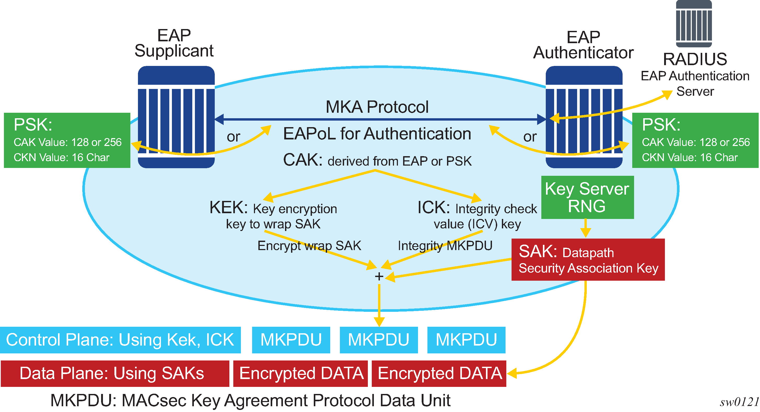
The node initially needs to secure the control plane communication to distribute the SAKs between two or more members of a CA domain.
The control plane is secured using a CAK, which is generated using one of the following methods:
EAPoL
preshared key
(CAK and CKN values are configured using the CLI). The following CAK and CKN rules apply.
CAK uses 32 hexadecimal characters for a 128-bit key, and 64 hexadecimal characters for a 256-bit key, depending on the algorithm used for control plane encryption; for example, aes-128-cmac or aes-256-cmac.
CKN is a 32-octet character (64 hex) and is the name that identifies the CAK. This allows each of the MKA participants to select which CAK to use to process a received MKPDU. MKA places the following restrictions on the format of the CKN:
it must comprise an integral number of octets, between 1 and 32 (inclusive)
all potential members of the CA must use the same CKN
CAK and CKN must match on peers to create a MACsec-secure CA.
The following figure shows MACsec control plane authentication and encryption.
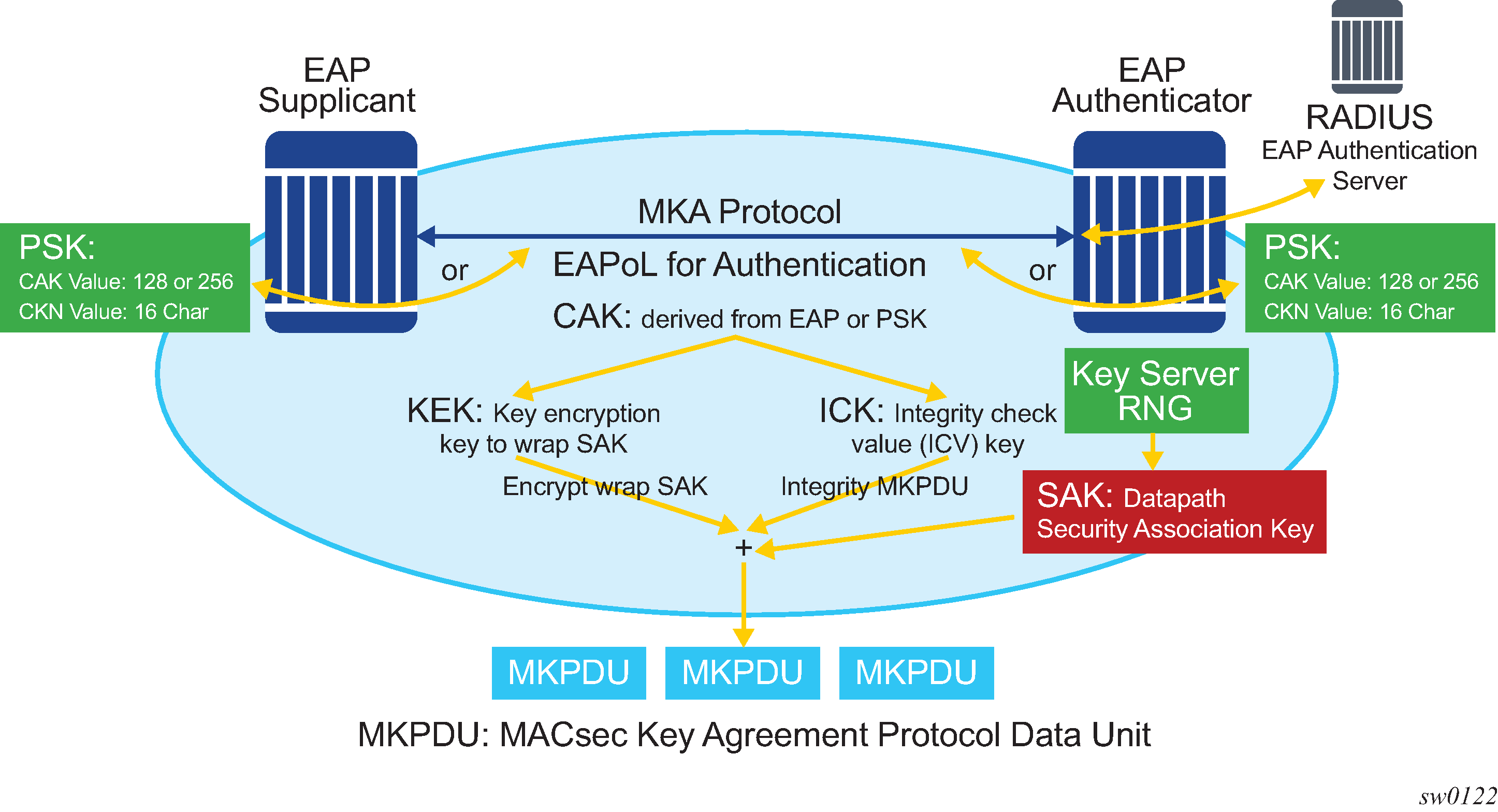
After the CAK is generated, it can obtain the following additional keys:
KEK (Key Encryption Key)
The KEK is used to wrap and encrypt the SAKs.
ICK (Integrity Connection Value (ICV) Key)
The ICK is used for an integrity check of each MKPDU send between two CAs.
The key server then creates a SAK and shares it with the CAs of the security domain, and that SAK secures all data traffic traversing the link. The key server periodically creates and shares a randomly created SAK over the point-to-point link for as long as MACsec is enabled.
The SAK is encrypted using the AES-CMAC, the KEK as the encryption key, and ICK as the integration key.
SAK rollover
The SAK is regenerated after the following events:
when a new host has joined the CA domain and MKA hellos are received from this host
when the sliding window is reaching the end of its 32-bit or 64-bit length
when a new PSK is configured and a rollover of PSK is executed
MKA
Each MACsec peer operates the MKA. Each node can operate multiple MKAs based on the number of CAs that it belongs to. Each instance of MKA is protected by a distinct secure CAK, that allows each Port Access Entity (PAE), or port, to ensure that information for a specific MKA instance is accepted only from other peers that also possess that CAK, therefore identifying themselves as members or potential members of the same CA. For a description of how the CAK identification is performed using CKN, see MACsec static CAK.
MKA PDU generation
The following table describes the MKA PDUs generated for different traffic encapsulation matches.
|
Configuration |
Configuration example (<s-tag>.<c-tag>) |
MKA packet generation |
Traffic pattern match/behavior |
Supported on 7210 SAS |
|---|---|---|---|---|
|
All-encap |
|
untagged MKA packet |
Matches all traffic on port, including untagged, single-tag, and double-tag. Default behavior. |
Yes |
|
UN-TAG |
|
untagged MKA packet |
Matches only untagged traffic on port |
No |
|
802.1Q single S-TAG (specific S-TAG) |
|
MKA packet generated with S-TAG=1 |
Matches only single-tag traffic on port with tagID of 1 |
No |
|
802.1Q single S-TAG (any S-TAG) |
|
untagged MKA packet |
Matches any dot1q single-tag traffic on port |
No |
|
802.1ad double tag (both tag have specific TAGs) |
|
MKA packet generated with S-tag=1 and C-TAG=1 |
Matches only double-tag traffic on port with service tag of 1 and customer tag of 1 |
No |
|
802.1ad double tag (specific S-TAG, any C-TAG) |
|
MKA packet generated with S-TAG=1 |
Matches only double-tag traffic on port with service tag of 1 and customer tag of any |
No |
|
802.1ad double tag (any S-TAG, any C-TAG) |
|
untagged MKA packet |
Matches any double-tag traffic on port |
No |
Tags in clear behavior by traffic encapsulation types
By default, all tags are encrypted in CA. An MKA can be generated without any tags (untagged), but the data being matched can be based on dot1q or q-in-q.
The following table describes how single or double tags in clear configuration under a CA affect different traffic flow encryptions.
Configuration |
Traffic pattern match/behavior |
CA configuration: no tag in cleartext form |
CA configuration: single-tag in cleartext form |
CA configuration: double-tag in cleartext form |
|---|---|---|---|---|
Port |
Matches all traffic on port, including untagged, single-tagged, double-tagged (default behavior) |
MKA PDU: untagged Untagged traffic: encrypted Single-tagged traffic: encrypted, no tag in clear Double-tagged traffic: encrypted, no tag in clear |
MKA PDU: untagged Untagged traffic: in clear Single-tagged traffic: encrypted, single-tag in clear Double-tagged traffic: encrypted, single-tagged in clear |
MKA PDU: untagged Untagged traffic: in clear Single-tagged traffic: in clear Double-tagged traffic: encrypted, double-tagged in clear |
PSK
A peer may support the use of one or more preshared keys (PSKs). An instance of MKA operates for each PSK that is administratively configured as active.
A preshared key is either created by NSP or configured using the CLI. Each PSK is configured using the following fields:
CKN
CAK value
The CKN must be unique for each port among the configured sub-ports, and can be used to identify the key in subsequent management operations.
Each static CAK configuration can have two preshared key entries for rollover. The active PSK index dictates which CAK is being used for encrypting the MKA PDUs.
NSP has additional functionality to rollover and configure the PSK. The rollover using NSP can be based on a configured timer.
MKA hello timer
MKA uses a member identifier (MI) to identify each node in the CA domain.
A participant proves liveness to each of its peers by including the MI, together with an acceptably recent message number (MN), in an MKPDU.
To avoid a new participant having to respond to each MKPDU from each partner as it is received, or trying to delay its reply until it is likely that MI MN tuples have been received from all potential partners, each participant maintains and advertises both a live peers list and a potential peers list.
The live peers list includes peers that have included the participant MI and a recent MN in a recent MKPDU. The potential peers list includes all other peers that have transmitted an MKPDU that has been directly received by the participant or that were included in the live peers list of a MKPDU transmitted by a peer that has proved liveness. Peers are removed from each list when an interval of between MKA lifetime and MKA lifetime plus MKA Hello Time has elapsed since the participant's recent MN was transmitted. This time is sufficient to ensure that two or more MKPDUs will have been lost or delayed before the incorrect removal of a live peer.
The specified use of the live peers and potential peers lists allows rapid removal of participants that are no longer active or attached to the LAN, while reducing the number of MKPDUs transmitted during group formation; for example, a new participant is admitted to an established group after receiving, then transmitting, one MKPDU.
MKA Hello packets are sent once every 2 seconds with a timeout interval of 3 packets or 6 seconds. These values are not configurable.
The following table lists the MKA participant timer values.
Timer use |
Timeout (parameter) |
Timeout (parameter) |
|---|---|---|
Per participant periodic transmission, initialized on each transmission on expiry |
MKA Hello Time or MKA Bounded Hello Time |
2.0 0.5 |
Per peer lifetime, initialized when adding to or refreshing the potential peers list or live peers list, expiry causes removal from the list |
MKA Life Time |
6.0 |
Participant lifetime, initialized when participant created or following receipt of an MKPDU, expiry causes participant to be deleted |
||
Delay after last distributing a SAK, before the key server distributes a fresh SAK following a change in the live peers list while the potential peers list is still not empty |
MACsec capability, desire, and encryption offset
The IEEE 802.1x-2010 standard identifies the following fields in the MKA PDU:
MACsec Capability
Desire
MACsec capability signals whether MACsec is capable of integrity and confidentiality. For information about the basic settings for MACsec capability, see the encryption-offset command description.
Encryption offset of 0, 30, or 50 starts from the byte after the SecTAG (802.1AE header). Ideally, the encryption offset should be configured for IPv4 (offset 30) and IPv6 (offset 50) to leave the IP header in cleartext. This allows routers and switches to use the IP header for LAG or ECMP hashing.
Key server
The participants in an MKA instance that agree on a key server are responsible for the following:
deciding on the use of MACsec
cipher suite selection
SAK generation and distribution
SA assignment
identifying the CA when two or more CAs merge
Each participant in an MKA instance uses the key server priority (an 8-bit integer) encoded in each MKPDU to agree on the key server. Each participant selects the live participant advertising the highest priority as its key server whenever the live peers list changes, provided that highest priority participant has not selected another as its key server or is unwilling to act as the key server.
If a key server cannot be selected, SAKs are not distributed. In the event of a tie for highest priority key server, the member with the highest priority SCI is chosen. For consistency with other uses of the SCI MAC address component as a priority, numerically lower values of the key server priority and SCI receive the highest priority.
Each SC is identified by an SCI that comprises a globally unique MAC address, and a port identifier unique within the system that has been allocated that address.
SA limits and network design
Each MACsec device supports 64 Tx-SAs and 64 Rx-SAs. An SA (Security Association) is the key to encrypt or decrypt the data.
As defined in IEEE 802.1AE, each SecY contains an SC. An SC is a unidirectional concept; for example, Rx-SC or Tx-SC. Each SC contains at least one SA for encryption on Tx-SC and decryption on Rx-SC. Also, for extra security, each SC should be able to roll over the SA, therefore, Nokia recommends for each SC to have two SAs for rollover purposes.
MACsec PHY is known as a MACsec security zone. Each MACsec security zone supports 64 Tx-SAs and 64 Rx-SAs. Assuming two SAs for each SC for SA rollover, each zone supports 32 Rx-SCs and 32 Tx-SCs.
The following table describes the port mapping to security zones.
|
Platform |
Ports in security zone 1 |
Ports in security zone 2 |
Ports in security zone 3 |
Ports in security zone 5 |
SA limit per security zone |
|---|---|---|---|---|---|
|
7210 SAS-K 2F6C4T |
Ports 1, 2, 3, 4 |
Ports 5, 6, 7, 8 |
Ports 9, 10, 11, 12 |
— |
Rx-SA = 64 Tx-SA = 64 |
|
7210 SAS-K 3SFP+ 8C |
Ports 1, 2, 3, 4 (1, 2, and 3 are 10GE ports) |
Ports 5, 6, 7, 8 |
Ports 9, 10, 11 |
— |
Rx-SA = 64 Tx-SA = 64 |
| 7210 SAS-Dxp 24p | — | — | — |
Ports 1/1/19 and 1/1/20 (1 GE ports) Ports 1/1/17 and 1/1/18 (10 GE ports) |
Rx-SA = 64 Tx-SA = 64 |
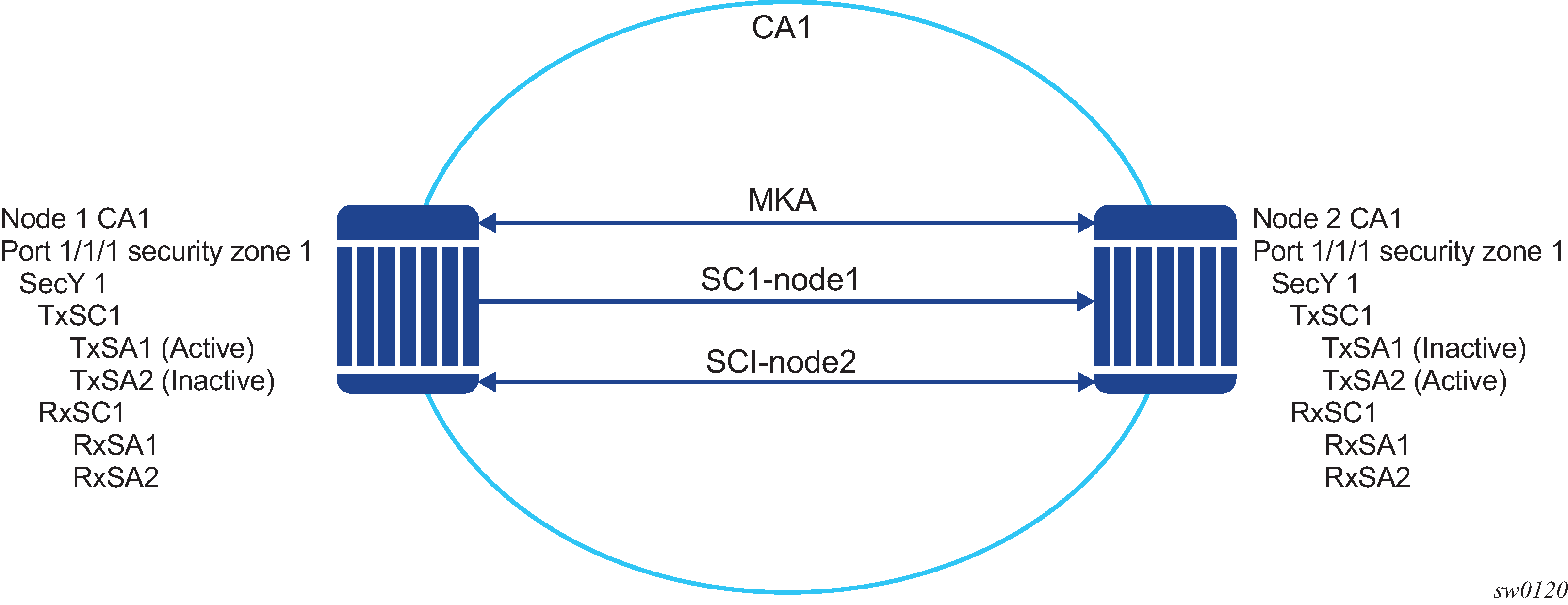
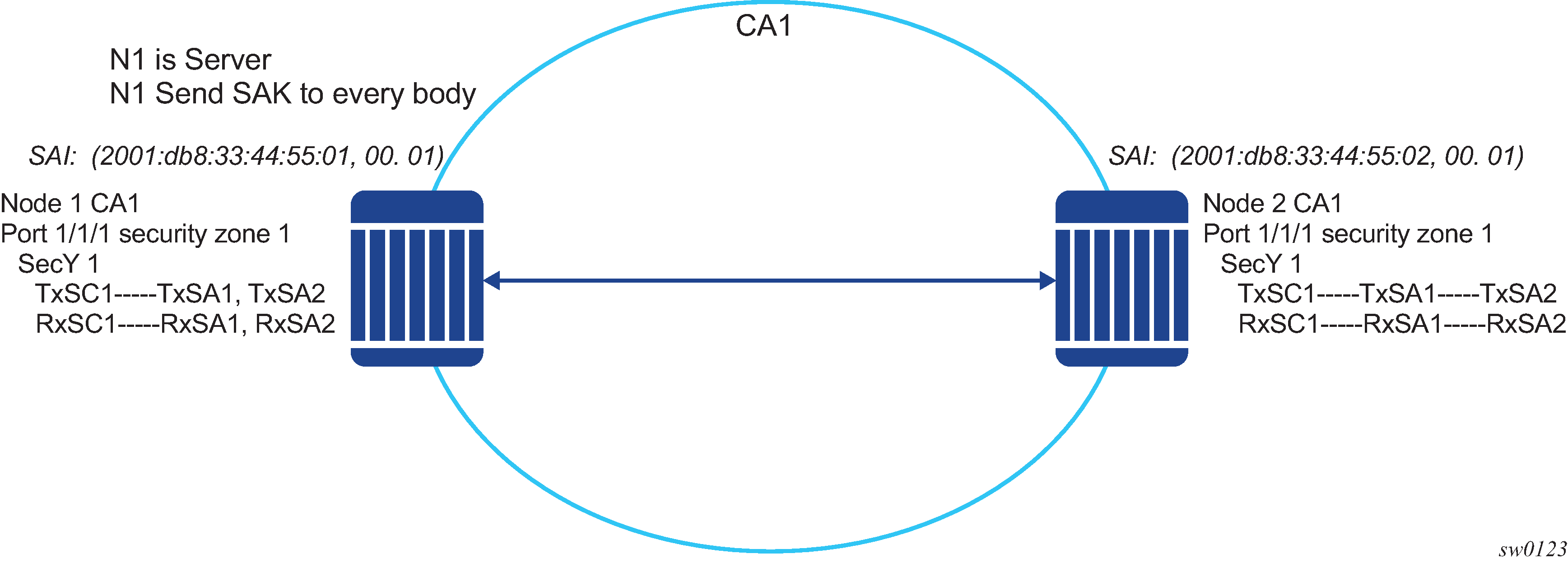
P2P (switch-to-switch) topology
In a point-to-point topology, each router needs a single security zone, a single Tx-SC for encryption, and a single Rx-SC for decryption. Each SC has two SAs. In total, for point-to-point topology, four SAs are needed: two Rx-SAs for Rx-SC1 and two Tx-SAs for Tx-SC1.
The following figure shows the P2P topology.
P2MP (switch to switch) topology
In a multi-point topology with N nodes, each node needs a single Tx-SC and N Rx-SC, one for each one of the peers. As such, 64 maximum Rx-SAs for each security zone translates to 32 Rx-SCs, which breaks down to only 32 peers; for example, only 33 nodes in the multipoint topology for each security zone. So from the perspective of each node, there is one Tx-SC and 32 Rx-SCs.
As shown in the following figure, when the 34th node joins the multi-point topology, the other 33 nodes that are already part of this domain do not have SAs to create an Rx-SC for this 34th node; however, the 34th node has a Tx-SC and can accept 32 peers. The 34th node starts to transmit and encrypt the PDUs based on its Tx-SC. However, because all other nodes do not have as SC for this SAI, all Rx PDUs are dropped.
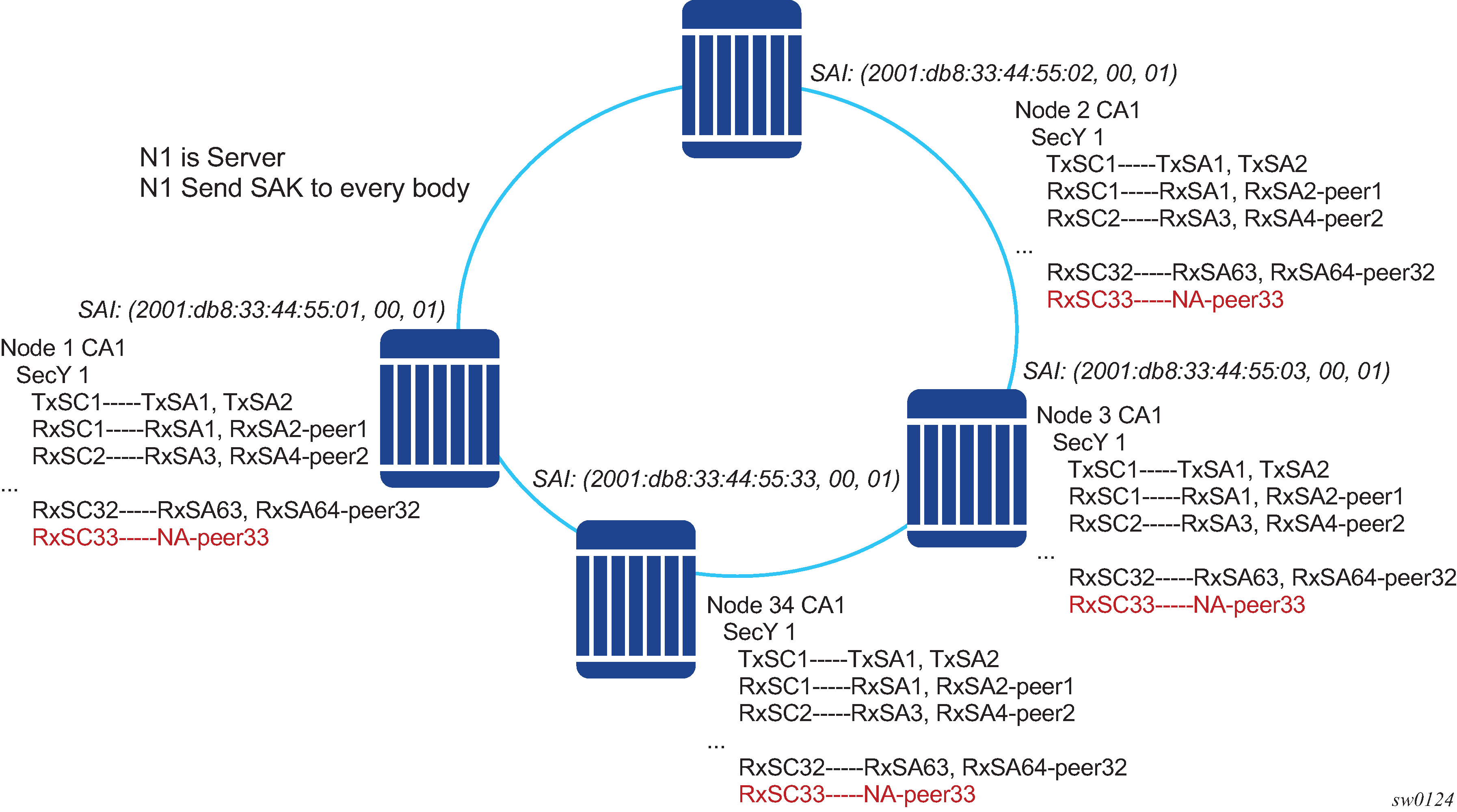
Nokia recommends that a multicast domain, for a single security zone, should not exceed 32 peers, or the summation of all the nodes in a security zone CA domain should not exceed 33. This is the same as if a security zone has four CAs; the summation of all nodes in the four CAs should be 33 or less.
SA exhaustion behavior
A security zone has 64 Rx-SAs and 64 Tx-SAs, as described in SA limits and network design. Two Rx-SAs are used for each Rx-SC for rollover purposes, and two Tx-SAs are used for Tx-SC for rollover purposes. This translates to 32 peers for each security zone.
Under each port, you can configure a max-peer command to assign the number of peers allowed on that port.
Ensure that the number of peers does not exceed the limit of maximum peers per security zone or maximum peers per port.
If the maximum peer is exceeded, the peer connectivity becomes random. In the case of a node failure or packet loss, peers join the CA randomly, on a first-come-first-served basis.
Nokia strongly recommends that the maximum peer value is not exceeded per security zone or port.
Clear tag mode
In most Layer 2 networks, MAC forwarding is done using a destination MAC address. The 802.1AE standard requires that any field after source and destination MAC address and after the SecTAG must be encrypted. This includes the 802.1Q tags. In some VLAN switching networks, it may be needed to leave the 802.1Q tag in cleartext form.
7210 SAS allows the configuration of 802.1Q tag in cleartext form by placing the 802.1Q tag before the SecTAG, or encrypts it by placing it after the SecTAG.
The following table lists the MACsec encryption of 802.1Q tags when the clear-tag is configured.
Unencrypted format |
Clear-tag-mode configuration |
Pre-encryption (Tx) |
Pre-decryption (Rx) |
|---|---|---|---|
Single tag (dot1q) |
Single-tag |
DA, SA, TPID, VID, Etype |
DA, SA, TPID, VID, SecTAG |
Single tag (dot1q) |
Double-tag |
DA, SA, TPID, VID, Etype |
DA, SA, TPID, VID, SecTAG |
Double tag (q-in-q) |
Single-tag |
DA, SA, TPID1, VID1, IPID2, VID2, Etype |
DA, SA, TPID1, VID1, SecTAG |
Double tag (q-in-q) |
Double-tag |
DA, SA, TPID1, VID1, IPID2, VID2, Etype |
DA, SA, TPID1, VID1, IPID2, VID2, SecTAG |
802.1X tunneling and multihop MACsec
MACsec is an Ethernet packet and, as with any Ethernet packet, can be forwarded through multiple switches using Layer 2 forwarding. The encryption and decryption of the packets is done using the 802.1x (MKA) capable ports.
To ensure that the MKA is not terminated on an intermediate switch or router, enable 802.1x tunneling on the corresponding port.
Verify if tunneling is enabled using the following command.
*A:SwSim28>config>port>ethernet>dot1x# info
----------------------------------------------
      tunneling
By enabling tunneling, the 802.1x MKA packets transit that port without being terminated, because such MKA negotiation does not occur on a port that has 802.1x tunneling enabled.
EAPoL destination address
The MKA packets are transported over EAPoL with a multicast destination MAC address.
In cases where a point-to-point connection from the MKA to a peer node over a Layer 2 multihop cloud is required, you can set the EAPoL destination MAC address to the peer MAC address. This forces the MKA to traverse multiple nodes and establish an MKA session with the specific peer.
Mirroring consideration
Mirroring is performed before MACsec encryption. Therefore, if a port is MACsec-enabled and is also mirrored, all the mirror packets are in cleartext form.
Ethernet combo ports on 7210 SAS-K 2F1C2T, 7210 SAS-K 2F6C4T, and 7210 SAS-K 3SFP+ 8C
The 7210 SAS-K 2F1C2T, 7210 SAS-K 2F6C4T, and 7210 SAS-K 3SFP+ 8C support combo ports. The combo port provides two physical interface options to the user. One option is to configure it as an SFP port allowing for fiber-based connectivity and speeds of 100/1000 Mb/s with the advantages of using suitable optics for longer reach. The other option is to configure it as a fixed copper port, which provides cheaper connectivity for shorter reach. The SFP port support 100/1000 Mb/s speeds and the copper port can support 10/100/1000Mbps speed. The combo port can be configured either as an SFP port or a copper port. Both interfaces cannot be used simultaneously.
7210 SAS-K 2F1C2T provide one Combo port
7210 SAS-K 2F6C4T provides six Combo ports
7210 SAS-K 3SFP+ 8C provides eight Combo ports
The 7210 SAS-Dxp 24p only supports a port speed of 1 Gb/s for SFP+ ports 17 and 18, and for SFP ports 19 and 20. Port speeds of 10 Mb/s and 100 Mb/s with a copper SFP and 100 Mb/s with a fiber SFP are not supported on ports 19 and 20. The 7210 SAS-Dxp 16p only supports a port speed of 1 Gb/s for SPF+ ports.