Link Layer Discovery Protocol
The IEEE 802.1ab Link Layer Discovery Protocol (LLDP) standard defines protocol and management elements suitable for advertising information to stations attached to the same IEEE 802 LAN. The protocol facilitates the identification of stations connected by IEEE 802 LANs or MANs, their points of interconnection, and access points for management protocols.
The LLDP helps the network operators to discover topology information. This information is used to detect and resolve network problems and inconsistencies in the configuration.
The following list is the information included in the protocol defined by the IEEE 802.1ab standard:
Connectivity and management information about the local station to adjacent stations on the same IEEE 802 LAN is advertised.
Network management information from adjacent stations on the same IEEE 802 LAN is received.
Operates with all IEEE 802 access protocols and network media.
Network management information schema and object definitions suitable for storing connection information about adjacent stations is established.
Provides compatibility with a number of MIBs.
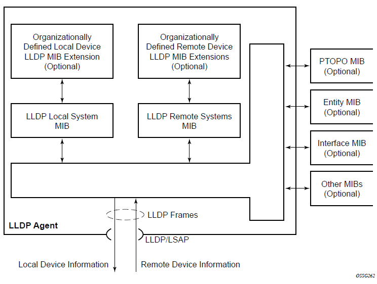
The following figure shows the internal architecture for a network node.
To detect and address network problems and inconsistencies in the configuration, the network operators can discover the topology information using LLDP. The Standard-based tools address the complex network scenarios where multiple devices from different vendors are interconnected using Ethernet interfaces.
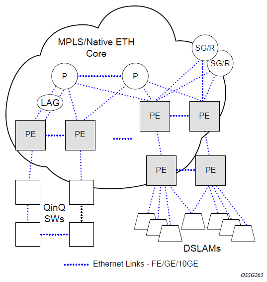
The following figure shows an MPLS network that uses Ethernet interfaces in the core or as an access/handoff interfaces to connect to different kind of Ethernet enabled devices such as service gateway/routers, QinQ switches DSLAMs or customer equipment.
The topology information of the network in the following figure can be discovered if, IEEE 802.1ab LLDP is running on each of the Ethernet interfaces in network.
LLDP protocol features
LLDP is an unidirectional protocol that uses the MAC layer to transmit specific information related to the capabilities and status of the local device. Separately from the transmit direction, the LLDP agent can also receive the same kind of information for a remote device which is stored in the related MIBs.
LLDP does not contain a mechanism for soliciting specific information from other LLDP agents, nor does it provide a specific means of confirming the receipt of information. LLDP allows the transmitter and the receiver to be separately enabled, making it possible to configure an implementation so the local LLDP agent can either transmit only or receive only, or can transmit and receive LLDP information.
The information fields in each LLDP frame are contained in a LLDP Data Unit (LLDPDU) as a sequence of variable length information elements, that each include type, length, and value fields (known as TLVs), where:
type identifies what kind of information is being sent
length indicates the length of the information string in octets
value is the actual information that needs to be sent (for example, a binary bit map or an alphanumeric string that can contain one or more fields)
Each LLDPDU contains four mandatory TLVs and can contain optional TLVs as selected by network management:
Chassis ID TLV
Port ID TLV
Time To Live TLV
Zero or more optional TLVs, as allowed by the maximum size of the LLDPDU
End Of LLDPDU TLV
The chassis ID and the port ID values are concatenated to form a logical identifier that is used by the recipient to identify the sending LLDP agent/port. Both the chassis ID and port ID values can be defined in a number of convenient forms. When selected however, the chassis ID/port ID value combination remains the same as long as the particular port remains operable.
A non-zero value in the TTL field of the Time To Live TLV tells the receiving LLDP agent how long all information pertaining to this LLDPDU identifier will be valid so that all the associated information can later be automatically discarded by the receiving LLDP agent if the sender fails to update it in a timely manner. A zero value indicates that any information pertaining to this LLDPDU identifier is to be discarded immediately.
Note that a TTL value of zero can be used, for example, to signal that the sending port has initiated a port shutdown procedure. The End Of LLDPDU TLV marks the end of the LLDPDU.
The implementation defaults to setting the port-id field in the LLDP OAMPDU to tx-local. This encodes the port-id field as ifIndex (sub-type 7) of the associated port. This is required to support some releases of SAM. SAM may use the ifIndex value to correctly build the Layer Two Topology Network Map. However, this numerical value is difficult to interpret or readily identify the LLDP peer when reading the CLI or MIB value without SAM. Including the port-desc option as part of the tx-tlv configuration allows an ALU remote peer supporting port-desc preferred display logic to display the value in the port description TLV instead of the port-id field value. This does not change the encoding of the port-id field. That value continues to represent the ifIndex. In some environments, it may be important to select the specific port information that is carried in the port-id field. The operator has the ability to control the encoding of the port-id information and the associated sub-type using the port-id-sub-type option. Three options are supported for the port-idsub-type:
tx-if-alias
Transmit the ifAlias String (sub-type 1) that describes the port as stored in the IFMIB, either user configured description or the default entry (ie 10/100/Gig Ethernet SFP)
tx-if-name
Transmits the ifName string (sub-type 5) that describes the port as stored in the IFMIB, ifName info
tx-local
The interface ifIndex value (sub-type 7)
IPv6 (address sub-type 2) and IPv4 (address sub-type 1) LLDP System Management addresses are supported.
LLDP tunneling for Epipe service
Customers who subscribe to Epipe service consider the Epipe as a wire, and run LLDP between their devices which are located at each end of the Epipe. To facilitate this, the 7210 SAS devices support tunneling of LLDP frames that use the nearest bridge destination MAC address.
If enabled using the command tunnel-nearest-bridge-dest-mac, all frames received with the matching LLDP destination MAC address are forwarded transparently to the remote end of the Epipe service. To forward these frames transparently, the port on which tunneling is enabled must be configured with NULL SAP and the NULL SAP must be configured in an Epipe service. Tunneling is not supported for any other port encapsulation or other services.
Additionally, before enabling tunneling, admin status for LLDP dest-mac nearest-bridge must be set to disabled or Tx only, using the command admin-status available under configure>port>ethernet>lldp>destmac-nearest-bridge. If admin-status for dest-mac nearest-bridge is set to receive and process nearest-bridge LLDPDUs (that is, if either rx or tx-rx is set) then it overrides the tunnel-nearest-bridge-dest-mac command.
The following table describes the behavior for LLDP with different values set in use for admin-status and when tunneling is enabled or disabled.
Nearest-bridge-mac admin status |
Tunneling enabled |
Tunneling disabled |
|---|---|---|
Rx |
Process/Peer |
Process/Peer |
Tx |
Tunnel |
Drop |
Rx-Tx |
Process/Peer |
Process/Peer |
Disabled |
Process/Peer |
Drop |
Transparent forwarding of LLDP frames can be achieved using the standard defined mechanism when using the either nearest-non-tmpr or the nearest-customer as the destination MAC address in the LLDP frames. Nokia recommends that the customers use these MAC address where possible to conform to standards. This command allows legacy LLDP implementations that do not support these additional destinations MAC addresses to tunnel LLDP frames that use the nearest-bridge destination MAC address.
LLDP media endpoint discovery
This feature is only supported on the 7210 SAS-Sx/S 1/10GE operating in the standalone or standalone-VC mode.
The IEEE standard 802.1AB is designed to provide a multivendor solution for the discovery of elements on an Ethernet Layer 2 data network. The LLDP standard allows nodes attached to an Ethernet LAN/WAN to advertise functionalities provided by that node to other nodes attached to the same LAN segment. See Link Layer Discovery Protocol for more information about IEEE 802.1AB.
The ANSI/TIA-1057 standard, Link Layer Discovery Protocol for Media Endpoint Devices, provides extensions to IEEE 802.1AB that are specific to media endpoint devices (MEDs), for example, voice phone and video terminal, in an IEEE 802 LAN environment. This standard defines specific usage of the IEEE 802.1AB LLDP base specification and interaction behavior between MEDs and LAN infrastructure elements.
LLDP media endpoint discovery (LLDP-MED) is an extension of LLDP that provides basic provisioning information to connected media endpoint devices. LLDP-MED extends LLDP protocol messages with more information to support voice over IP (VoIP) applications.
On the 7210 SAS, LLDP-MED supports the exchange of network policy information to provide the VLAN ID, dot1p bits, and IP DSCP value to media endpoint devices such as a VoIP phone.
The following TLVs are supported for LLDP-MED:
LLDP-MED Capabilities TLV
Network Policy TLV
LLDP-MED reference model
LLDP-MED devices are composed of two primary device types: network connectivity devices and endpoint devices.
LLDP-MED network connectivity devices provide access to the IEEE 802 LAN infrastructure for LLDP-MED endpoint devices. An LLDP-MED network connectivity device is a LAN access device based on any of the following technologies:
LAN switch or router
IEEE 802.1 bridge
IEEE 802.3 repeater
IEEE 802.11 wireless access point
any device that supports the IEEE 802.1AB and MED extensions defined by the standard and that can relay IEEE 802 frames using any method
Endpoint devices are composed of three sub-types, as defined in ANSI/TIA-1057:
generic endpoints (Class I)
This endpoint device class is for basic endpoints in LLDP-MED (for example, IP communications controllers).
media endpoints (Class II)
This endpoint device class supports IP media streams (for example, media gateways and conference bridges).
communication device endpoints (Class III)
This endpoint device class support the IP communication system end user (for example, IP telephones and softphones).
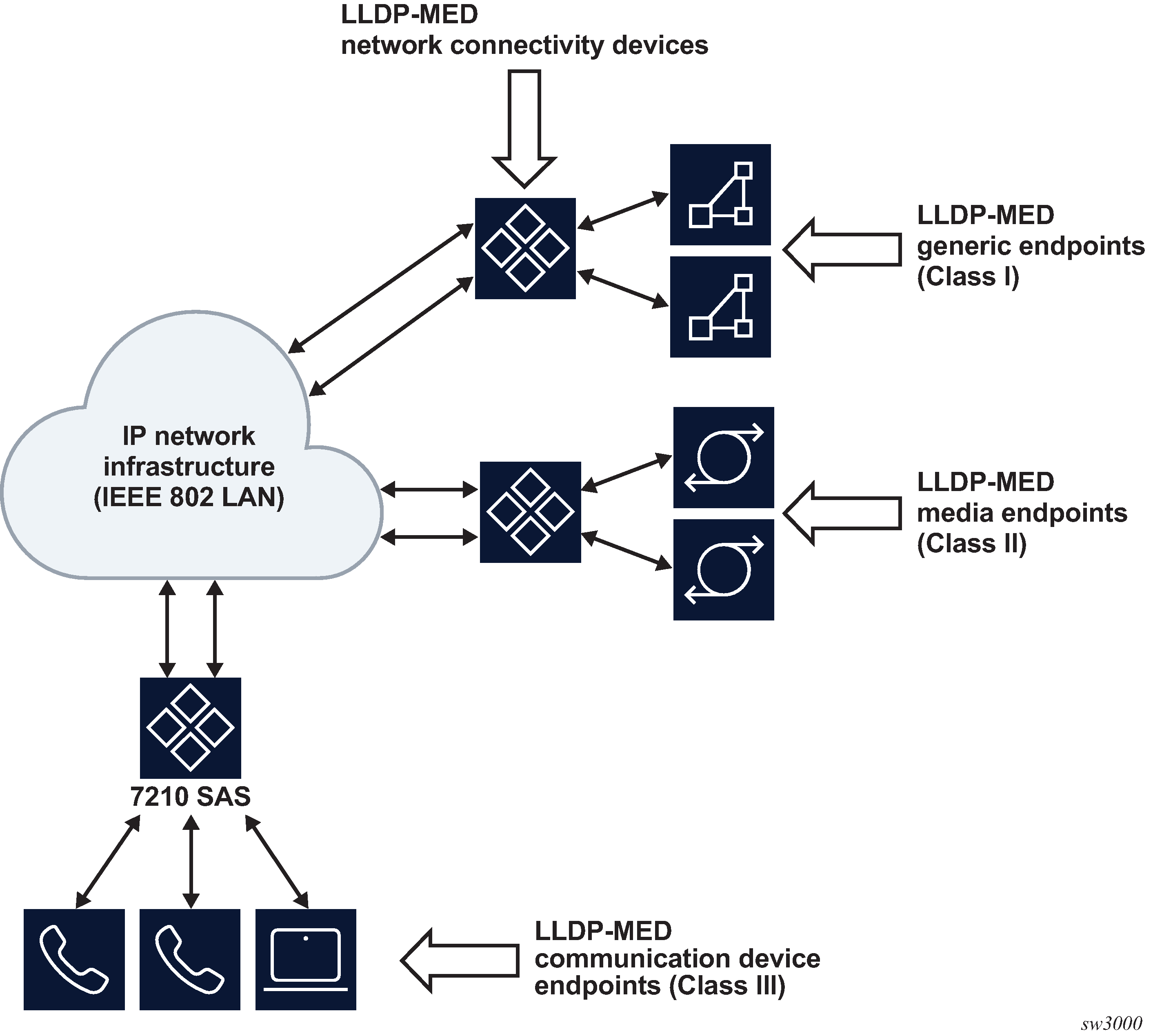
The following figure shows the LLDP-MED reference model.
Acting as the network connectivity device, the 7210 SAS only supports the configuration of LLDP-MED communication device endpoints (Class III), such as VoIP phone, using the Network Policy TLV.
LLDP-MED network connectivity device functions
To enable LLDP-MED network connectivity device functions, configure the config port ethernet lldp dest-mac lldp-med admin-status command. When this command is configured, the behavior of the node is as follows:
If admin-status is set to rx-tx, the LLDP agent transmits and receives LLDP-MED TLVs on the port. The 7210 SAS node includes the LLDP-MED Capabilities TLV and the Network Policy TLV (if configured) in the LLDP message that is generated in response to an LLDP message with the LLDP-MED Capabilities TLV received on the port.
If admin-status is set to disabled, the 7210 SAS ignores and does not process the LLDP-MED Capabilities TLV in the LLDP message received on the port.
The configure port ethernet lldp admin-status command must be enabled for LLDP-MED TLV processing. The admin-status configuration in the lldp context must not conflict with the admin-status configuration in the lldp-med context.
When LLDP-MED is enabled on the port, the Network Policy TLV is sent out of the port using the parameters configured for the network policy that is associated with the port.
See the 7210 SAS-Mxp, R6, R12, S, Sx, T Basic System Configuration Guide for more information about configuring network policy parameters using commands in the config>system>lldp>lldp-med context.
LLDP-MED endpoint device move notification
The endpoint move detection notification enables VoIP management systems to track the movement of VoIP phones. On the 7210 SAS, the user has the option to generate the lldpXMedTopologyChangeDetected event on detection of movement of the endpoint device. By default, the event is disabled. To enable the event, configure the config>log>event-control lldp generate and config>port>ethernet>lldp> dest-mac>nearest-bridge>notification commands.
Modified use of TLVs defined in LLDP
LLDP-MED modifies the usage of some LLDP base TLVs for network connectivity devices. Specifically, the 7210 SAS supports the transmission of the MAC/PHY Configuration Status TLV when LLDP-MED is enabled. The transmission of this TLV is enabled using the config>port>ethernet>lldp>dest-mac>lldp-med>tx-tlvs mac-phy-config-status CLI command option.