Pseudowire ports
This chapter provides information about pseudowire ports (PW ports), process overview, and implementation notes.
Overview
A PW port is primarily used to provide PW termination with the following characteristics:
Provide access (SAP) based capabilities to a PW which has traditionally been a network port based concept within SR OS. For example, PW payload can be extracted onto a PW-port-based SAPs with granular queuing capabilities (queuing per SAP). This is in contrast with traditional PW termination on network ports where queuing is instantiated per physical port on egress or per MDA on ingress.
-
Lookup dot1q and qinq VLAN tags underneath the PW labels and map the traffic to different services.
-
Terminate subscriber traffic carried within the PW on a BNG. In this case PW-port-based SAPs are instantiated under a group interface with Enhanced Subscriber Management (ESM). In this case, a PW-port-based SAP is treated as any other regular SAP created directly on a physical port with full ESM capabilities.
The PW-port coverage expands beyond the TLDP-signaled pseudowires and encompass termination of all tunnel types (MPLS, GRE, VXLAN, L2oGRE, SRv6, and so on) and signaling methods (TLDP, BGP-EVPN, BGP-VPSW, and so on) that can be configured under an Epipe service.
Mapping between PWs and PW ports is performed on one-to-one basis.
There are two modes in which PW port can operate:
-
a PW port bound to a specific physical port (I/O port)
A successful mapping between the PW and PW port requires that the PW terminates on the same physical port (I/O port) to which the PW port is bound. In this mode of operation, PW ports do not support re-routing of PWs between the I/O ports. For example, if a PW is rerouted to an alternate physical port because of a network failure, the PW port becomes non-operational.
-
a PW port independent of the physical port (I/O port) on which the PW is terminated
This capability relies on FPE functionality, therefore, the name FPE based PW port. The benefit of such PW port is that it can provide services in cases where traffic within PW is rerouted between I/O ports because of a network failure.
When the PW port is created, the mapping between the PW port and PW depends on the mode of operation and application.
PW port creation:
     configure
        pw-port <id>
            encap-type {dot1q|qinq}
Similar to any other Ethernet-based port, the PW port supports two encapsulation types, dot1q and qinq. Ether-type on a PW port is not configurable and it is set to a fixed value of 0x8100 for dot1q and qinq encapsulation.
PW port bound to a physical port
In this mode of operation, the PW port is bound to a specific physical port through an SDP binding context:
    configure
        service
            sdp 1 mpls create
                far-end 10.10.10.10
                ldp
                binding
                    port 1/1/1
                    pw-port 1 vc-id 11 create
                        egress
                        shaping inter-dest-id vport-1
In this example, pw-port 1 is bound to a physical port 1/1/1.This PW port is mapped to the PW with vc-id 11 under the sdp 1 which must be terminated on port 1/1/1.A PW port is shaped by a virtual port scheduler (Vport) construct named vport-1 configured under port 1/1/1. SAPs created under such PW ports can be terminated in ESM, Layer 3 IES/VPRN interface or in an Epipe.
FPE-based PW port
The FPE based PW-port is primarily used to extract a PW payload onto an access based PW-port SAP, independent of the network I/O ports. FPE uses Port Cross-Connect (PXC) ports and provides an anchoring point for PW-port, independent of I/O ports, the term anchored PW-port can be interchangeably used with the term FPE based PW-port. The following are examples of applications which rely on FPE based PW-port:
ESM over PW where MPLS/GRE based PW can be rerouted between I/O ports on an SR OS node without affecting ESM service
-
Granular QoS per PW because the PW payload is terminated on an access based PW-port SAP → ingress/egress queues are created per SAP (as opposed to per network port on egress and per MDA on network ingress)
-
PW-SAP with MPLS resiliency, where the LSP used by the PW terminated on a PW Ports is protected using MPLS mechanisms such as FRR and could therefore use any port on the system
-
PW-port using LDP-over-RSVP tunnels
-
A PW Port using a BGP VPWS
Although the primary role of FPE based PW-port is to terminate an external PW, in certain cases PW-port can be used to terminate traffic from regular SAP on I/O ports. This can be used to:
-
Separate service termination point from the SAPs which are tied to I/O ports.
-
Distribute load from a single I/O port to multiple line cards based on S-Tag (traffic from each S-tag can be mapped to a separate PW associated with different PXCs residing on different line cards).
Cross-connect between the external PW and the FPE-based PW-port
PW payload delivery from the I/O ports to the FPE based PW-port (and SAP) is facilitated via an internal cross-connect which is built on top of PXC sub-ports. Such cross-connect allows for mapping between PWs and PW-ports even in cases where PW payloads have overlapping VLANS. This concept is shown in Multiplexing PWs over PXC-based internal cross-connect .
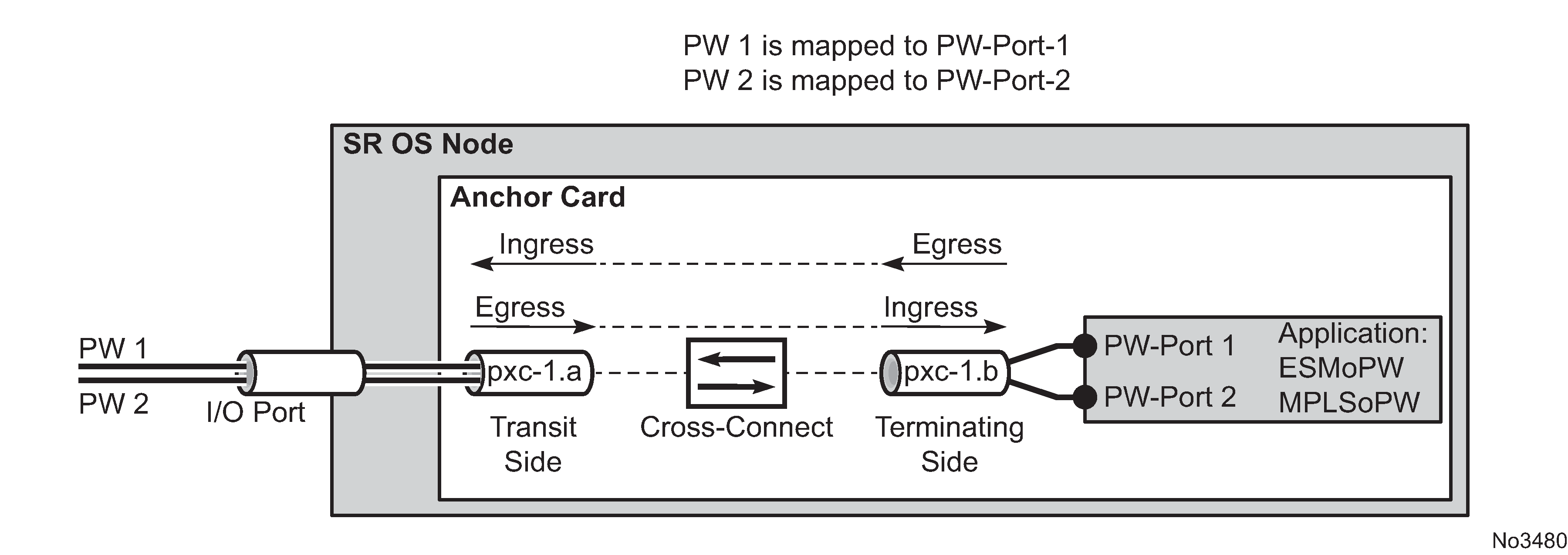
Parameters associated with the PXC sub-ports or PXC based LAGs (QoS, lag-profiles, and so on) are accessible/configurable through CLI. For example, the operator may apply an egress port-scheduler on sub-port pxc-1.b in Multiplexing PWs over PXC-based internal cross-connect to manage the sum of the bandwidth from associated PW-ports (PW-ports 1 and 2). To avoid confusion during configuration of PXC sub-ports /LAGs, a clear definition of reference points on the cross-connect created through FPE is required:
-
Terminating side of the cross-connect is closer to PW-ports (.b side)
-
Transit side of the cross-connect is closer to I/O ports (.a side)
Because the creation of the cross-connect on FPE based PW-ports is highly automated through and FPE configurations, the SR OS system:
-
Assign PXC sub-ports .a to the transit side, and PXC sub-ports .b to the terminating side in case that a single PXC is used; see Assign PXC sub ports .
Figure 2. Assign PXC sub ports 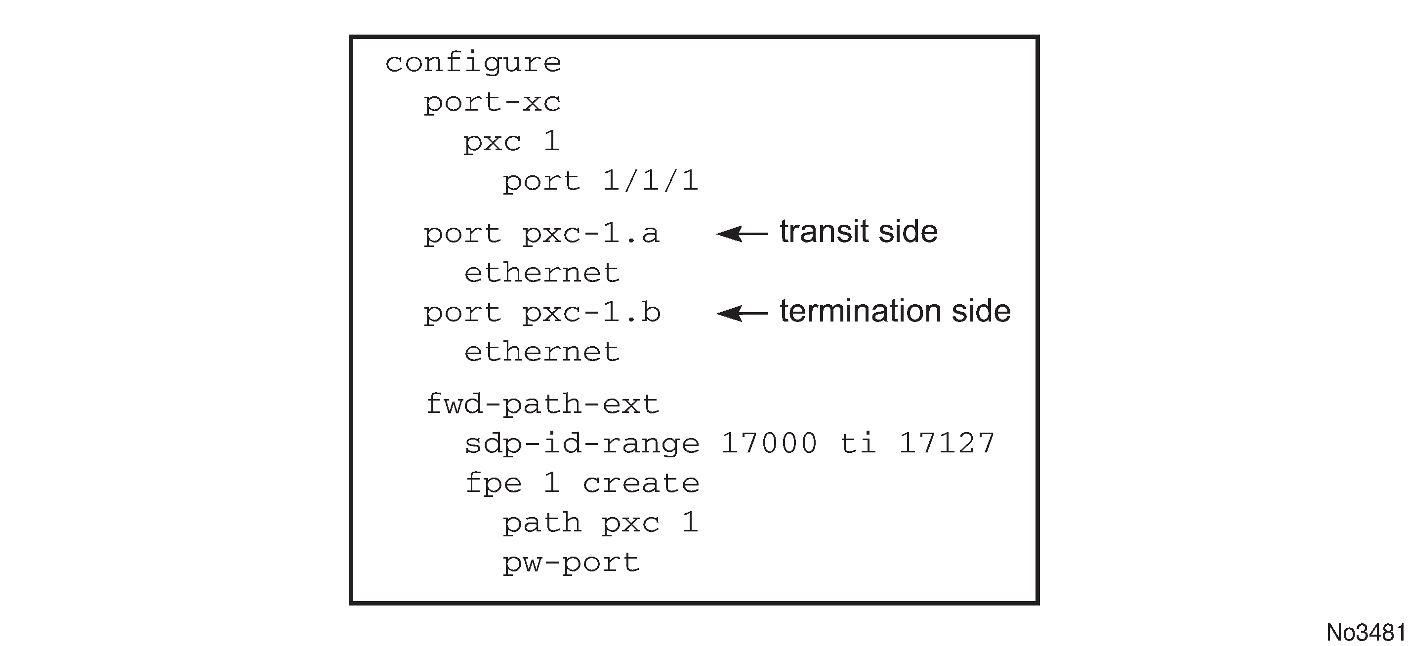
-
Assign the xc-a LAG to the transit side, and the xc-b LAG to the terminating side if that a PXC based LAG is used; see Assign the LAG .
Figure 3. Assign the LAG 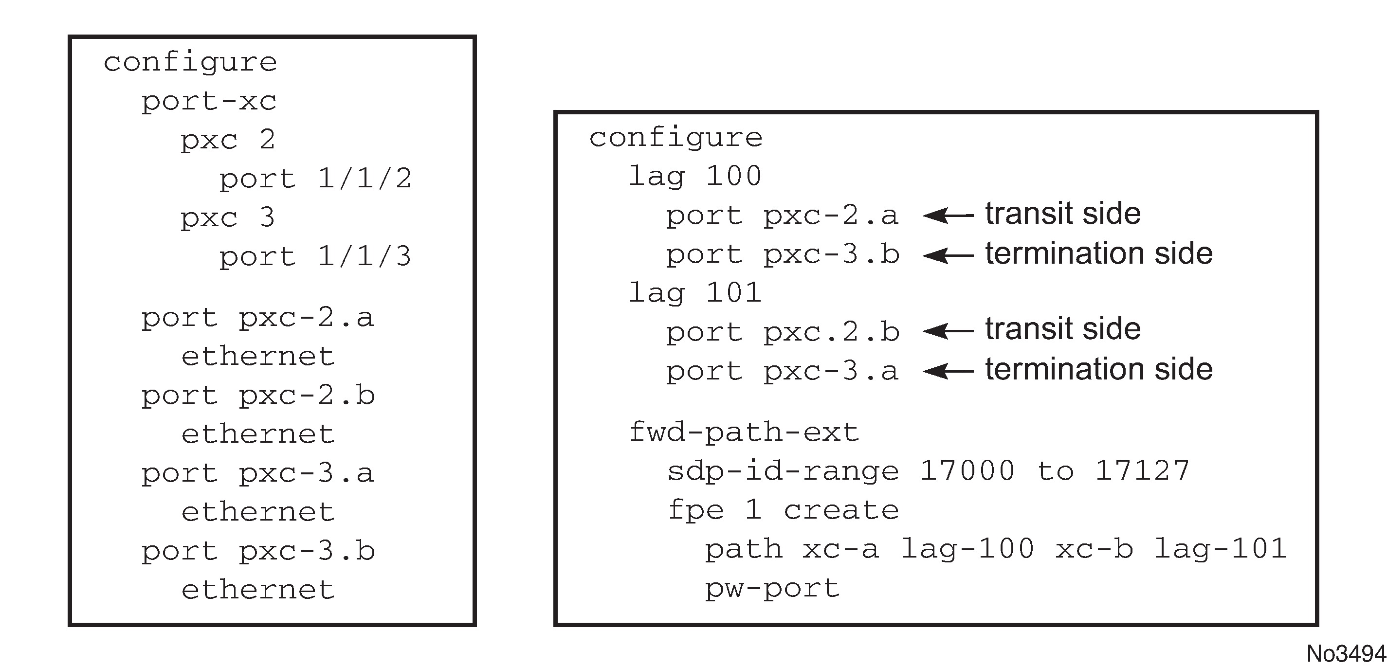
xc-a and xc-b can be associated with any PXC based LAG ID. For example, the following path configuration is allowed: xc-a with lag-id 100 (which includes pxc sub-ports pxc-2.a and pxc-3.b) and xc-b with lag-id 101 (which includes pxc sub-ports pxc-3.a and pxc-2.b). Regardless of the pxc sub-ports that are assigned to respective LAGs, the xc-a side of the path is used as the transit side of the cross-connect, while the xc-b side of the path is used as the termination side of the cross-connect.
PXC-based PW-port — building the cross-connect
From a logical perspective, the internal cross-connect that maps the external PW to a PW-port is implemented as a switched Epipe service (vc-switching). This switched Epipe service switches an external PW to the internal PW that is terminated on a FPE based PW-port. In this fashion, the PW-port becomes independent of the I/O ports. Assuming that PXC and PW-port are already configured in the system, the following are the three main configuration steps required to terminate the payload carried over external PW on the PW-port SAP:
Auto-setup of the internal transport tunnel over which the cross-connect is built
Auto-setup of the internal PW, switching the external PW to the internal PW and terminating the PW on the FPE based PW-port
Terminating the service on the PW-SAP
The status of the internally built constructs can be examined via various show commands (for example, show service id <epipe-id> 1 sdp). The internal SDP ID is allocated from the user space. To avoid conflict between the user provisioned SDP IDs and the system provisioned SDP IDs, a range of SDP ids that is used for internal consumption must be reserved in advance. This is accomplished via the sdp-id-range commands under the config>fwd-path-ext hierarchy.
Configuration steps necessary to build PW-port based cross-connect over PXC are shown in the following diagrams (a single PXC is used in this example).
Building the internal transport tunnel
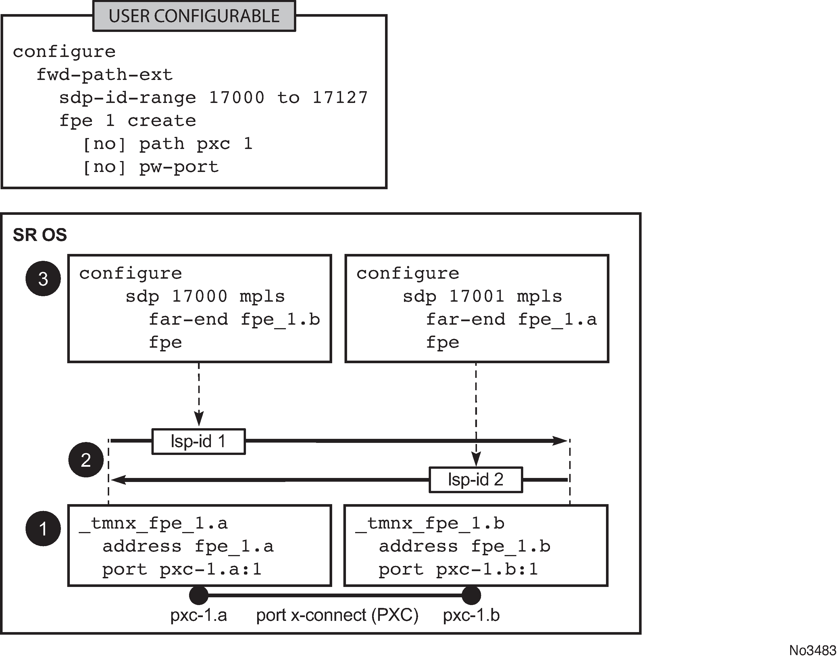
The fpe command instructs the SR OS system to build an LSP tunnel over the PXC. This tunnel is used to multiplex PW traffic to respective PW-ports. Each external PW is switched to an internal PW (on top of this tunnel) and its payload is off-loaded to a respective PW-port.
After the fpe is configured (see the 7450 ESS, 7750 SR, 7950 XRS, and VSR Interface Configuration Guide, "Forwarding Path Extensions"), the SR OS system automatically configures steps 1, 2 and 3 in Building the internal LSP over PXCs. The objects created in steps 1, 2 and 3 can be seen via show commands. However, they are not visible to the operator in the configure branch of CLI.
The significance of the pw-port command under the FPE is to inform the system about the kind of cross-connect that needs to be built over PXC – in this case this cross-connect is PW-port specific. Applications other than PW-port may require different functionality over PXCs and this is reflected by a different command under the FPE CLI hierarchy (for example, vxlan-termination command instead of pw-port).
Note that the IP addresses setup on internal interfaces on PXC sub-ports are Martian IP addresses and they are shown in CLI as fpe_<id>.a and fpe_<id>.b.
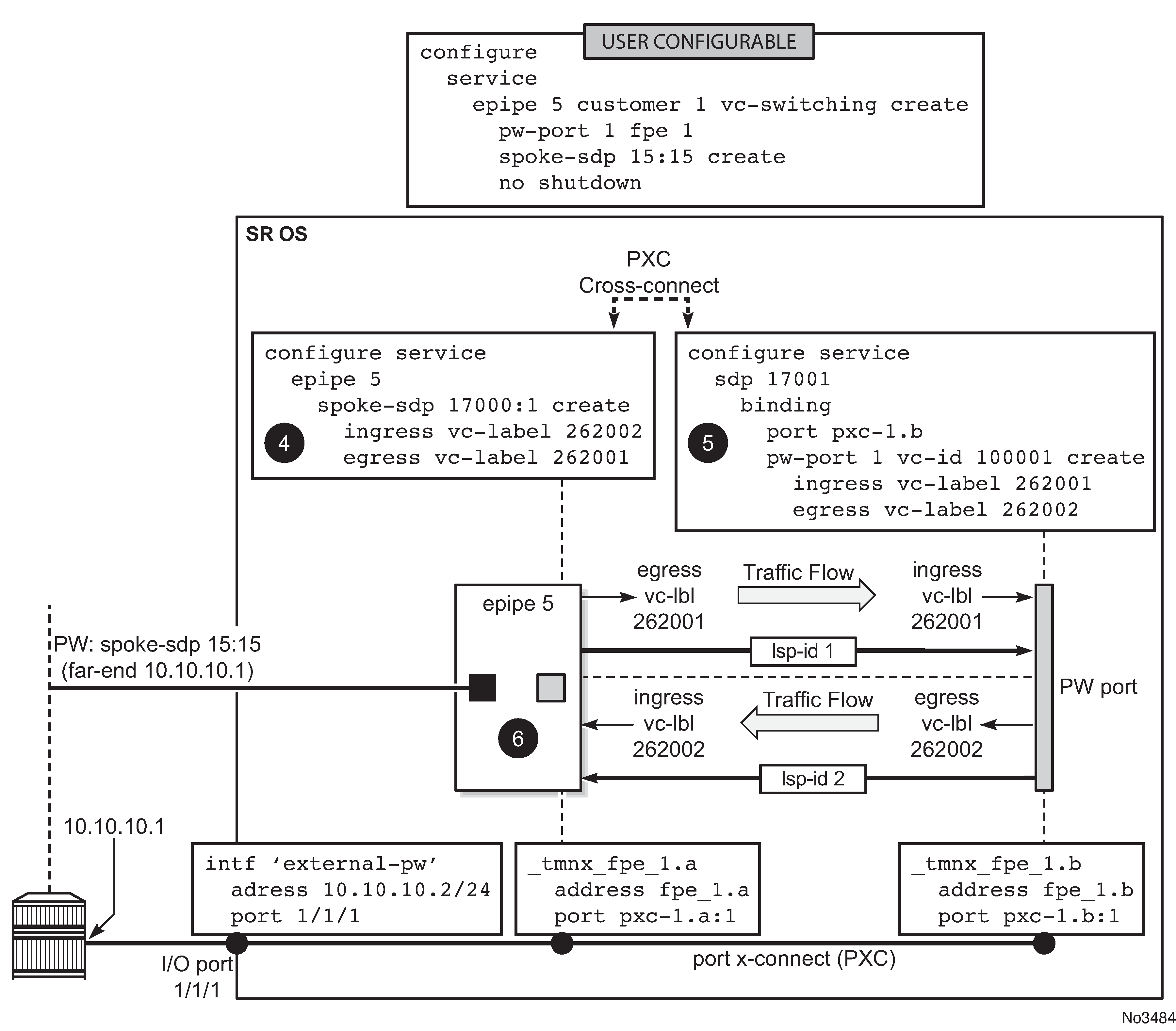
Mapping the external PW to the PW-port
Mapping between the external PW and the FPE based PW-port is performed via an Epipe of type vc-switching. The user configurable Epipe (id 5 in this example) aids in setting up steps 4, 5 and 6 in Mapping between the external PW and the PXC based PW-port:
An internal PW is automatically added to the user configured Epipe 5.
A bind is created between the internal PW and the PW-port attached to PXC.
External PW is switched to the internal PW.
At this stage, the external PW is mapped to the pw-port 1, as shown in Mapping between the external PW and the PXC based PW-port. The spoke-sdp 17000:1 and the binding under SDP 17001 (spoke-sdp 17001:100001) created in steps 4 and 5 (Mapping between the external PW and the PXC based PW-port) can be seen via show commands. However, they are not visible to the operator in the configure branch of CLI.
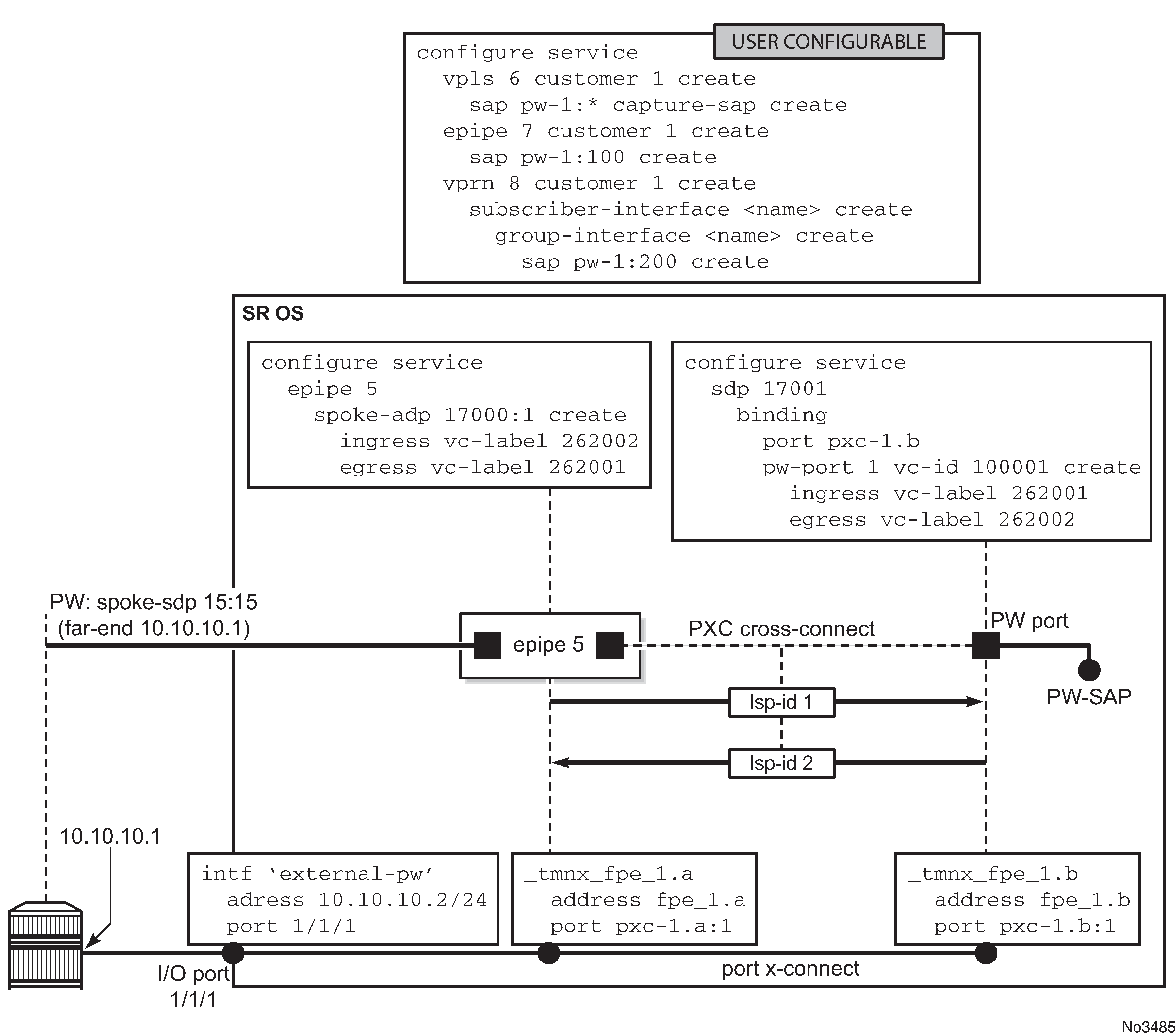
Terminating the service on PW-SAP
In the final step, PW-port SAP is applied to a service (Service termination on PW-SAP).
FPE-based PW port operational state
The ability of the stitching service to forward traffic drives the FPE-based PW port operational state. This includes the operational status of the stitching service and, if the external PW is TLDP signaled, the PW status bits. The stitching service operational status transitions to a non-operational state if the EVPN network destination, a BGP-VPWS spoke-SDP, or a configured spoke-SDP is operationally down.
With a TLDP-signaled PW, the operational state of the PW port depends on the PW status bits received from the peer, even if the stitching service is operationally up:
- The PW port transitions into a non-operational state if the PW Preferential Forwarding bit (pwFwdingStandby) is received from the peer (the PW is in standby mode).
- The PW port transitions into a non-operational state if the Local Attachment Circuit (LAC) or Local Packet Switched Network (PSN) faults are received from the peer (lacIngressFault, lacEgressFault, psnIngressFault, and psnEgressFault). The operator must explicitly enable this behavior through CLI. By default, the aforementioned fault bits received from the peer do not affect the state of the PW port.
Transitioning of the PW port into the down state because of a PXC failure (for example physical port fails) brings the stitching service down with the following result:
-
In case of a TLDP-signaled PW, the psnIngressFault and psnEgressFault PW status bits are propagated to the remote end, indicating that the local stitching service is down.
-
In case of an EVPN, the EVPN route is withdrawn, indicating that the local stitching service is down.
-
In case of a BGP-VPWS, the BGP-VPWS ‛D’ bit of the Layer 2 Information Extended Community flag field is set, indicating that the local stitching service is down.
By default, if a PW port is mated to a T-LDP-signaled PW (for example, a spoke-SDP) across an FPE in an Epipe service, the PW port operational state only reacts to the following PW status bit being set on the received T-LDP status message:
pwFwdingStandby (5) -- Pseudo Wire in Standby mode
When the down-on-peer-tldp-pw-status-faults command is configured, the PW port only goes locally operationally down if any of the following PW status bits are received on the mate spoke-SDP:
pwNotForwarding (0), -- Pseudo Wire Not Forwarding
lacIngressFault (1), -- Local Attachment Circuit Rx Fault
lacEgresssFault (2), -- Local Attachment Circuit Tx Fault
psnIngressFault (3), -- Local PSN-facing PW Rx Fault
psnEgressFault (4), -- Local PSN-facing PW Tx Fault
If the configuration is removed, the system no longer takes the mate PW status fault bits into account in the operational state of the PW port.
-
Classic CLI commands
configure service epipe epipe-id customer cust-id vc-switching [create] pw-port pw-port-id fpe fpe-id spoke-sdp sdp-id:vc-id [create] or bgp-vpws -
MD-CLI commands
configure
      service epipe string
            customer reference vc-switching
            spoke-sdp sdp-id:vc-id
                  or
            bgp-vpws
      pw-port number
            epipe epipe-id
                fpe-id reference
-
Classic CLI commands
configure service epipe epipe-id customer cust-id create pw-port pw-port-id fpe fpe-id bgp-evpn -
MD-CLI commands
configure
      service epipe string
            customer reference
            bgp-evpn
      pw-port number
            epipe epipe-id
                fpe-id reference
QoS
QoS fundamentals for the case where multiple PWs are multiplexed over a single cross-connect are shown in QoS on FPE-based PW-port.
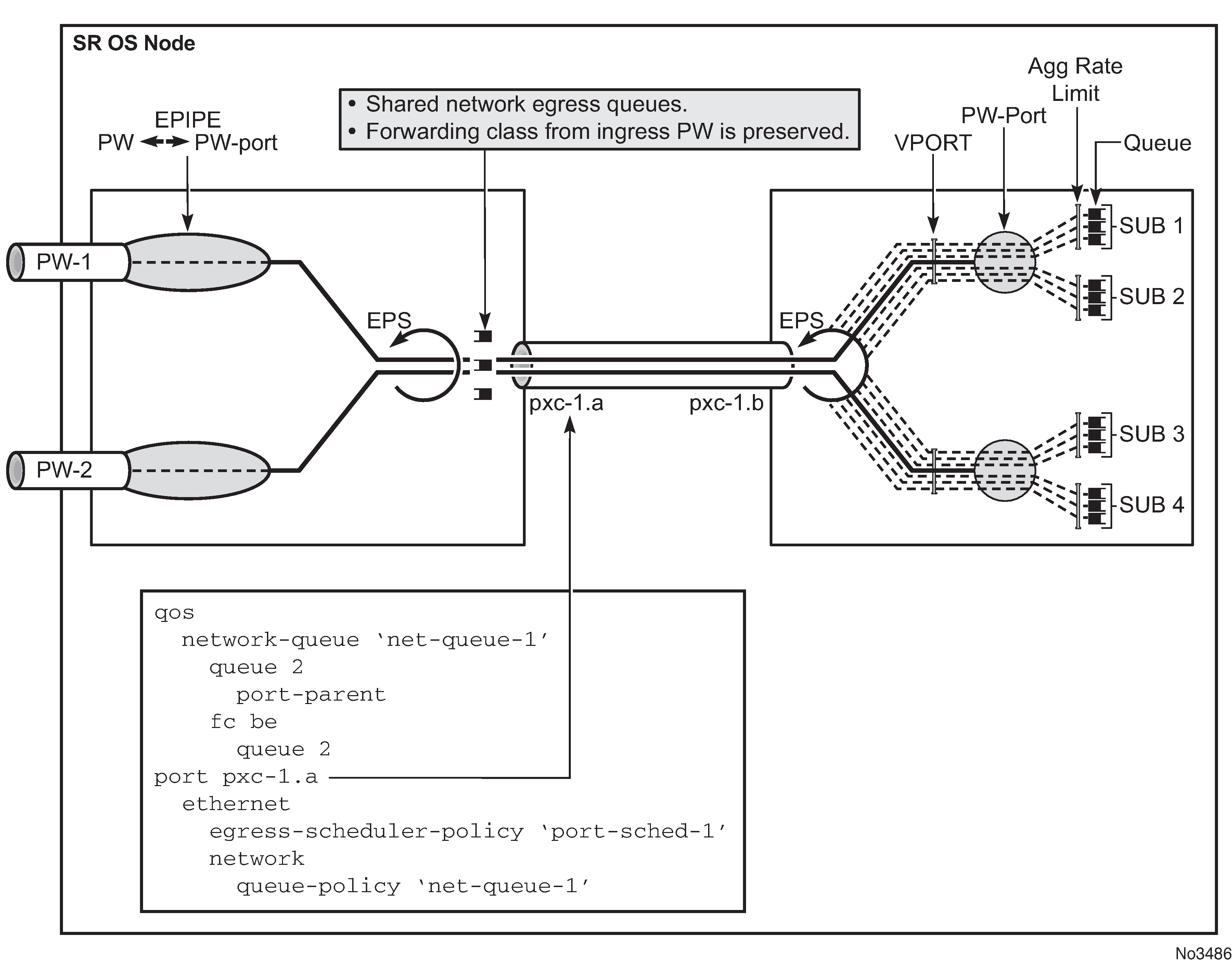
Egress QoS may be applied on both sides of the cross-connect (PXC sub-ports .a and .b) to control congestion on the cross-connect itself. This can be accomplished via an Egress Port Scheduler (EPS) applied to each sub-port.
EPS applied to pxc-1.a (transit side) manages congestion on the cross-connect for traffic coming from the external PWs. A single set of queues is shared by all PWs utilizing this cross-connect in this direction.
EPS applied to the pxc-1.b (terminating side) is used to manage congestion on the cross-connect for traffic going toward the PWs (leaving the SR OS node). A set of queues is dedicated to each PW-port SAP.
QoS on PXC sub-ports is described in the 7450 ESS, 7750 SR, 7950 XRS, and VSR Interface Configuration Guide, "PXC".
Preservation of forwarding class across PXC
The internal cross-connect used by FPE based PW-port is relying on an MPLS tunnel built over internal network interfaces configured on PXCs. Those internal network interfaces are using a default network policy 1 for egress traffic classification, remarking and marking purposes. Because the PXC cross-connect is MPLS based, the EXP bits in newly added MPLS header is marked according to the default network policy (for brevity reasons, only the relevant parts of the network policy are shown here).
*A:node-1>config>qos>network# info detail
----------------------------------------------
            description "Default network QoS policy."
            scope template
            egress
                fc af
                    lsp-exp-in-profile 3
                    lsp-exp-out-profile 2
                exit
                fc be
                    lsp-exp-in-profile 0
                    lsp-exp-out-profile 0
                exit
                fc ef
                    lsp-exp-in-profile 5
                    lsp-exp-out-profile 5
                exit
                fc h1
                    lsp-exp-in-profile 6
                    lsp-exp-out-profile 6
                exit
                fc h2
                    lsp-exp-in-profile 4
                    lsp-exp-out-profile 4
                exit
                fc l1
                    lsp-exp-in-profile 3
                    lsp-exp-out-profile 2
                exit
                fc l2
                    lsp-exp-in-profile 1
                    lsp-exp-out-profile 1
                exit
                fc nc
                    lsp-exp-in-profile 7
                    lsp-exp-out-profile 7
                exit
            exit
----------------------------------------------
As seen in this excerpt from the default network egress policy, the forwarding classes AF and L1 marks the EXP bits with the same values. This renders the forwarding classes AF and L1 set on one side of PXC, indistinguishable from each other on the other side of the PXC.
This effectively reduces the number of forwarding classes from 8 to 7 in deployment scenarios where the QoS treatment of traffic depends on preservation of forwarding classes across PXC. That is, in such scenarios, one of the forwarding classes AF or L1 should not be used.
Statistics on the FPE based PW-port
An FPE-based PW-port is associated with an internal spoke-SDP as described in PXC-based PW-port — building the cross-connect and FPE-based PW port operational state. Statistics for the number of forwarded/dropped packets/octets per direction on a PW-port are therefore maintained per this internal spoke-SDP. Octets field counts octets in customer frame (including customer’s Ethernet header with VLAN tags). The following command is used to display PW-port statistics along with the status of the internal spoke-SDP associated with the PW-Port:
*A:Dut-B# show pw-port 3 statistics
===============================================================================
Service Destination Point (Sdp Id 17000 Pw-Port 3)
===============================================================================
SDP Binding port     : pxc-1.b
VC-Id                : 100003                Admin Status       : up
Encap                : dot1q                 Oper Status        : up
VC Type              : ether
Admin Ingress label  : 262135                Admin Egress label : 262136
Oper Flags           : (Not Specified)
Monitor Oper-Group   : (Not Specified)
Statistics            :
I. Fwd. Pkts.        : 12000                 I. Dro. Pkts.      : 0
I. Fwd. Octs.        : 720000                I. Dro. Octs.      : 0
E. Fwd. Pkts.        : 12000                 E. Fwd. Octets     : 720000
===============================================================================
Intra-chassis redundancy models for PXC-based PW port
Intra-chassis redundancy models rely on PXC-based LAG. PXC-based LAG can contain multiple PXCs on the same line card (port redundancy) or PXCs across different line cards (port- and card-level redundancy).
FPE-based PW ports also provide network level-redundancy where MPLS/IP can be rerouted to different I/O ports (because of network failure) without interruption of service.
PW ports and MTU
PW port based traffic is subject to a number of MTU checks, some of which depend on the tunnel type and signaling method. Downstream traffic (toward the remote end of the tunnel) is forced through several MTU checks in the data plane, and an MTU size violation can cause fragmentation or a packet drop. Other MTU checks are performed only in the control plane.
In TLDP tunnels, the service MTU is negotiated through signaling in the control plane where values on both sides of the tunnel must match, otherwise, the tunnel fails to transition into an operational state.
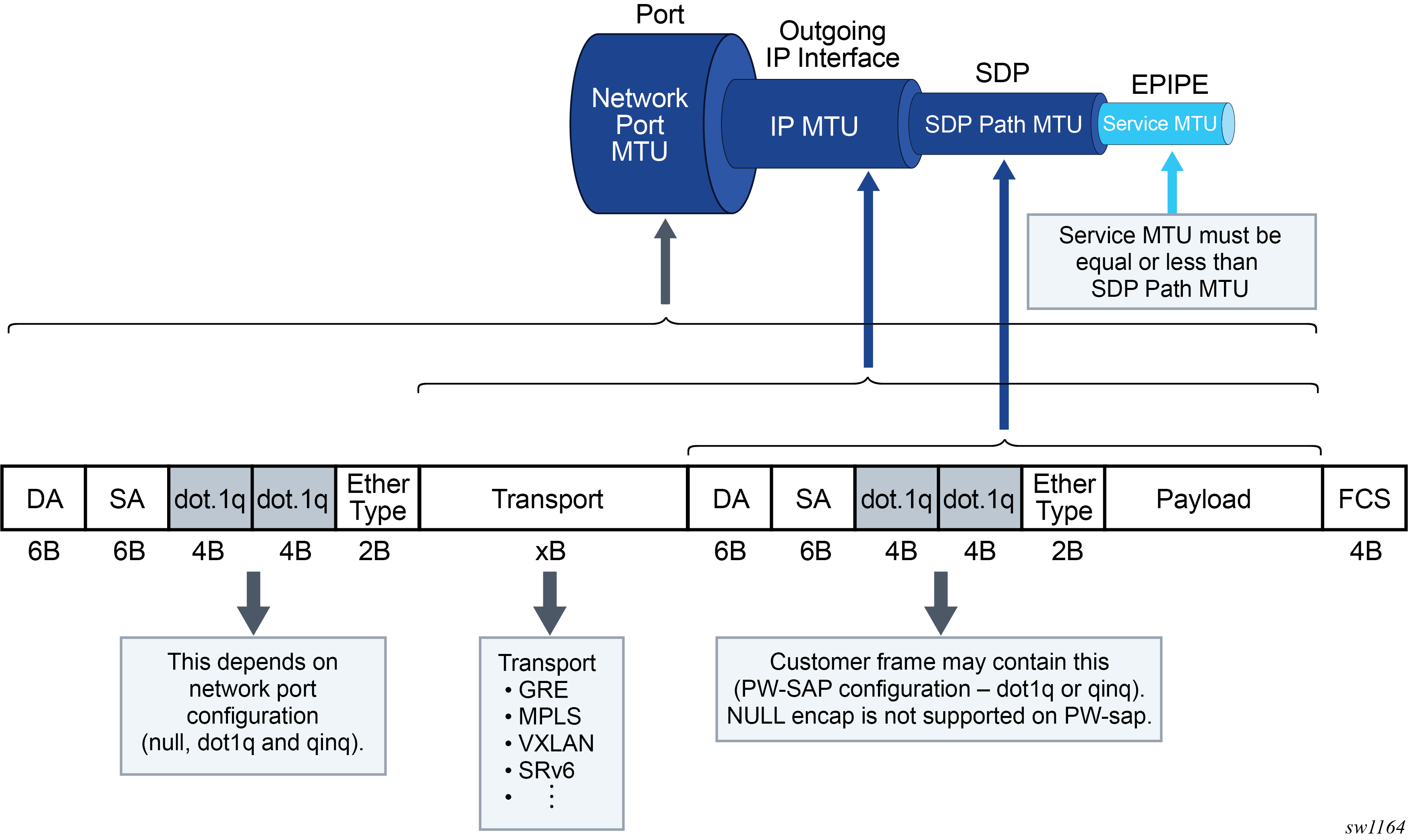
A generic SDP-based tunnel (such as a L2oGRE or TLDP GRE/MPLS tunnel) under an Epipe service has the following configurable MTUs:
- Port MTU represents the maximum frame size on the outgoing physical port. This is configured under the physical port and is enforced in the data plane.
- IP MTU is the maximum IP packet size on the outgoing IP interface. This is configurable under an IP interface and is enforced in the data plane.
- SDP path MTU represents the maximum size of the frame that is encapsulated within the tunnel (excluding the transport header). Its value is determined based on the smallest MTU size on the path between the endpoints of the tunnel. In SR OS, this SDP path MTU is calculated automatically by subtracting the size of the transport header from the configured IP MTU of the outgoing interface. This is configurable under the SDP and is enforced in the data plane.
- Service MTU indicates the maximum frame size of the customer payload that can be
transmitted over the service. Its value is determined by the MTU size within the
customer’s network. The service MTU is significant because it can customize the size
of the customer’s payload independently of the MTUs in the transport network. The
service MTU is negotiated using signaling and must match on both sides of the
tunnel. This MTU is not enforced in the data plane.
The service MTU is configured under the Epipe service, which is also the basic configuration construct used for FPE-based PW ports. Hence, the service MTU configured under the Epipe service also applies to FPE-based PW ports.
However, fixed PW ports (bound to a fixed port) are not configured under an Epipe service and therefore the service MTU configuration under the Epipe is inaccessible. Fixed PW ports are stitched to the tunnel within the SDP context with the configure service sdp binding command. This requires a separate configuration for the service MTU. Considering that fixed PW ports support only TLDP-signaled MPLS and GRE pseudowires in which the service MTU is advertised from each endpoint of the pseudowire, the adv-service-mtu command signals the service MTU for fixed PW ports.
Classic CLI
>config>service# info
----------------------------------------------
        sdp 1 mpls create
            far-end 10.20.1.3
            ldp
            binding
                port lag-1
                pw-port 1 vc-id 10 create
                    [no] adv-service-mtu <1..9782>
                    no shutdown
                exit
MD-CLI
[gl:configure pw-port 1]
    sdp 1 {
        admin-state enable
        vc-id 10
        adv-service-mtu 1514
    }
MSS and PW ports
A scheduler with a Multi-Service-Site (MSS) can be used to control aggregate bandwidth over multiple PW SAPs. This MSS can be associated with PW SAPs created under different PW ports that are bound to the same physical port, LAG, or an FPE object. This functionality is supported for the following SR OS PW port types:
Fixed PW-port that is bound to a physical port or LAG
FPE based PW-port that is using the PXC concept
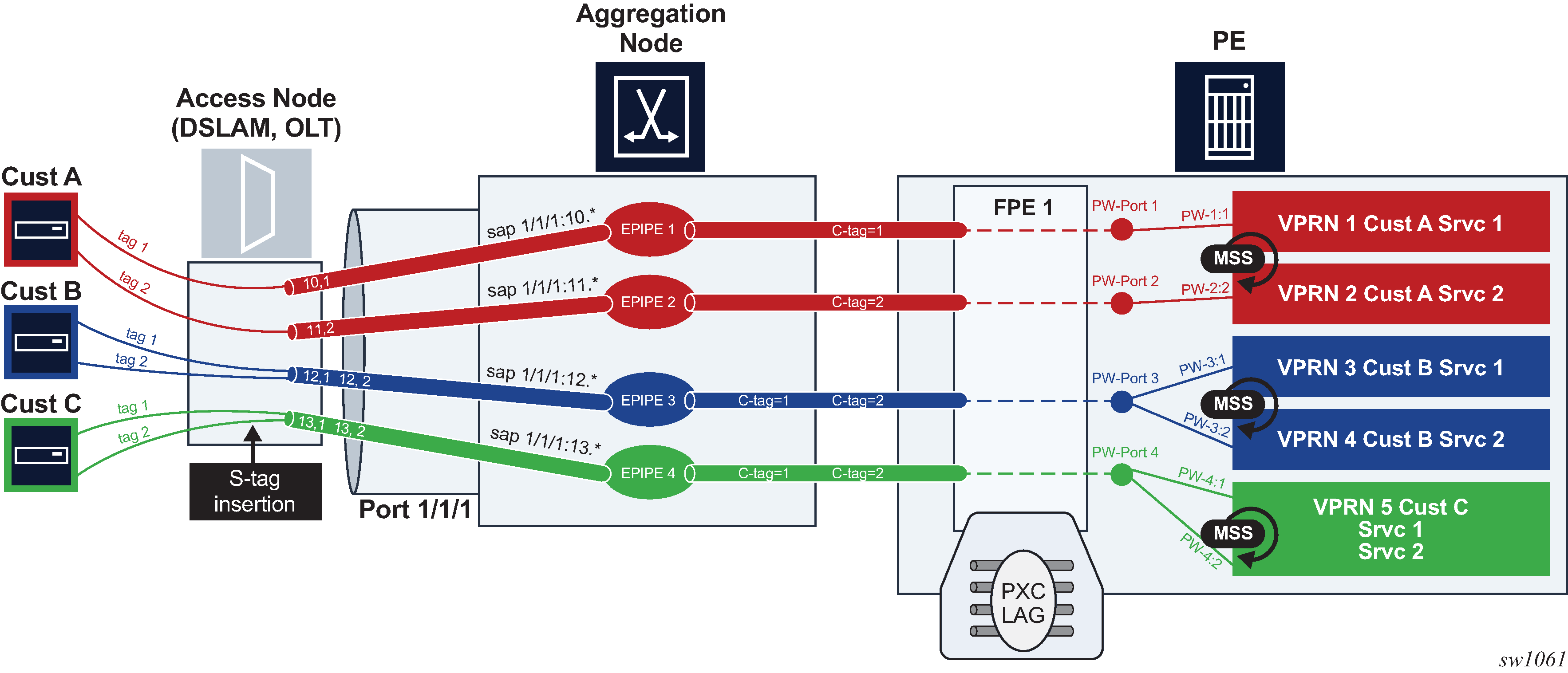
An example of MSS applied to PW SAPs is shown in MSS on PW SAPs where three MSSes are applied to PW SAPs across multiple PW ports and VPRNs. Although the PW SAPs can span multiple VPRNs and PW ports, the underlying physical port, LAG or an FPE object must be shared for a set of PW SAPs under the same MSS instance.
Configuration examples
The following are examples for fixed PW ports.
PW port declaration
configure pw-port 1 encap-type qinq-type : configure pw-port 2 encap-type qinq-type-
Binding a PW port to a spoke SDP
configure service sdp 2 far-end <ip-address> binding port lag-1 pw-port 1 vc-id 10 pw-port 2 vc-id 11 -
Create an MSS
configure service customer 1 multi-service-site ‟mss-PW port” assignment port lag-1 -
Apply MSS to all PW SAPs (associated with the same customer ID), and possibly belonging to different PW ports for aggregate bandwidth control within a Layer 3 (Intf) or a Layer 2 (Epipe) service. In this example, PW SAPs pw-1:1.1 and pw-1:2.2 belong to two different PW ports (1 and 2) on the same physical port/LAG.
    configure service IES/VPRN/EPIPE
        sap pw-1:1.1 create
                multi-service-site mss-pw port
                        egress
                qos <id>

    service ies/vprn/epipe
        sap pw-2:2.2 create
                multi-service-site mss-pw port
                        egress
                                qos <id>
The following are configuration examples for FPE-based PW ports:
PW port declarations
configure pw-port 1 encap-type qinq-type : configure pw-port 2 encap-type qinq-type :-
Configure PXC (with specific ports)
    configure port-xc
        pxc 1
                port 1/1/1
        pxc 2
                port 2/2/2
In classic CLI, sub-ports are automatically created.
    configure
        port pxc-1.a
        port pxc-1.b
        port pxc-2.a
        port pxc-2.b
In MDI-CLI, sub-ports must be manually created.
PXC LAG configuration
configure lag 100 port pxc-1.a port pxc-2.a configure lag 200 port pxc-1.a port pxc-2.b-
FPE configuration
configure fwd-path-ext fpe 1 path xc-a lag-100 xc-b lag 200 pw-port -
PW port binding
configure service epipe 5 customer 1 vc-switching pw-port 1 fpe 1 spoke-sdp 1:2 epipe 6 customer 1 vc-switching pw-port 2 fpe 1 spoke-sdp 1:3 -
Create an MSS
configure service customer 1 create multi-service-site mss-fpe-pw-port assignment fpe 1 -
Apply MSS to all PW SAPs that are associated with the same customer ID and possibly belonging to different PW ports for aggregate bandwidth control within a Layer 3 (Intf) or a Layer 2 (Epipe) services. In this example, PW SAPs pw-1:1.1 and pw-1:2.2 belong to two different PW ports (1 and 2) on the same physical port/LAG.
configure service ies/vprn/epipe ... sap pw-1:1.1 create multi-service-site mss-pw-port egress qos <id> -
configure service ies/vprn/epipe
...
        sap pw-2:2.2 create
                multi-service-site mss-pw-port
                egress
                        qos <id>
Concurrent scheduling QoS mechanisms on a PW port
An assortment of PW SAPs assigned to ESM and business services (non-ESM) can coexist under the same PW port. The scheduling hierarchy for each set of SAPs is configured differently and supported concurrently. For example, ESM subscribers can use their own scheduling hierarchy, while the business service’s PW SAPs on the same PW port can continue to use their own scheduling (via MSS, or however the business SAP scheduling hierarchy is set up).
Show command examples
The following are examples of the MSS and PW port command output.
show service customer 1 site "mss"
===============================================================================
Customer  1
===============================================================================
Customer-ID        : 1
Customer Name      : 1
Contact            : (Not Specified)
Description        : Default customer
Phone              : (Not Specified)
Creation Origin    : manual

-------------------------------------------------------------------------------
Multi Service Site
-------------------------------------------------------------------------------
Site               : mss
Description        : (Not Specified)
Assignment         : FPE 1
I. Sched Pol       : (Not Specified)
E. Sched Pol       : (Not Specified)
Egr Agg Rate Limit : 50000
Q Frame-Based Acct : Disabled
Limit Unused BW    : Disabled
E. Plcr Ctrl Polcy : (Not Specified)
I. Plcr Ctrl Polcy : (Not Specified)

-------------------------------------------------------------------------------
Service Association
-------------------------------------------------------------------------------
Service-Id         : 1 (Epipe)
 - SAP : pw-1:100
Service-Id         : 2 (VPRN)
 - SAP : pw-2:100
show qos agg-rate customer 1 site "mss"
===============================================================================
Aggregate Rate Information - Customer 1 MSS mss
===============================================================================
Root (Egr)
| slot(3)
|    AdminRate              : 50000
|    OperRate               : 50000
|    Limit Unused Bandwidth : disabled
|    OnTheWireRates         : false
|    LastMileOnTheWireRates : false
|
|--(Q) : 2->pw-2:100->8  (Port pxc-1.b)
|
|--(Q) : 2->pw-2:100->7  (Port pxc-1.b)
|
|--(Q) : 2->pw-2:100->6  (Port pxc-1.b)
|
|--(Q) : 2->pw-2:100->5  (Port pxc-1.b)
|
|--(Q) : 1->pw-1:100->8  (Port pxc-1.b)
|
|--(Q) : 1->pw-1:100->7  (Port pxc-1.b)
|
|--(Q) : 1->pw-1:100->6  (Port pxc-1.b)
|
|--(Q) : 1->pw-1:100->5  (Port pxc-1.b)
show qos scheduler-hierarchy customer 1 site "mss"
===============================================================================
Scheduler Hierarchy - Customer 1 MSS mss
===============================================================================
Root (Ing)
|
No Active Members Found on slot 3
Root (Egr)
| slot(3)
|--(Q) : 2->pw-2:100->8  (Port pxc-1.b)
|
|--(Q) : 2->pw-2:100->7  (Port pxc-1.b)
|
|--(Q) : 2->pw-2:100->6  (Port pxc-1.b)
|
|--(Q) : 2->pw-2:100->5  (Port pxc-1.b)
|
|--(Q) : 1->pw-1:100->8  (Port pxc-1.b)
|
|--(Q) : 1->pw-1:100->7  (Port pxc-1.b)
|
|--(Q) : 1->pw-1:100->6  (Port pxc-1.b)
|
|--(Q) : 1->pw-1:100->5  (Port pxc-1.b)
|
show>qos>policer-hierarchy# customer 1 site mss
===============================================================================
Policer Hierarchy - Customer 1 MSS mss
===============================================================================
root (Ing)
|
No Active Members Found on slot 1
root (Egr)
|
| slot(1/1)
|    Profile-preferred:Disabled
|
|--(A) : policer1 (Customer: 1, MSS: mss)
|   |
|   |--(P) : Policer 2->pxc-1.b:100->1
|   |   |
|   |   |    [Level 1 Weight 1]
|   |   |    Assigned PIR:5000       Offered:5000
|   |   |    Consumed:5000
|   |   |
|   |   |    Assigned FIR:5000
|   |
|   |--(P) : Policer 1->pxc-1.b:100->1
|   |   |
|   |   |    [Level 1 Weight 1]
|   |   |    Assigned PIR:5000       Offered:10000
|   |   |    Consumed:5000
|   |   |
|   |   |    Assigned FIR:5000
|
|--(A) : policer2 (Customer: 1, MSS: mss)
|   |
|   |--(P) : Policer 2->pxc-1.b:100->2
|   |   |
|   |   |    [Level 1 Weight 1]
|   |   |    Assigned PIR:5000       Offered:15000
|   |   |    Consumed:5000
|   |   |
|   |   |    Assigned FIR:5000
|   |
|   |--(P) : Policer 1->pxc-1.b:100->2
|   |   |
|   |   |    [Level 1 Weight 1]
|   |   |    Assigned PIR:5000       Offered:20000
|   |   |    Consumed:5000
|   |   |
|   |   |    Assigned FIR:5000
|
|--(A) : policer34 (Customer: 1, MSS: mss)
|   |
|   |--(A) : policer3 (Customer: 1, MSS: mss)
|   |   |
|   |   |--(P) : Policer 2->pxc-1.b:100->3
|   |   |   |
|   |   |   |    [Level 1 Weight 1]
|   |   |   |    Assigned PIR:10000      Offered:25000
|   |   |   |    Consumed:10000
|   |   |   |
|   |   |   |    Assigned FIR:10000
|   |   |
|   |   |--(P) : Policer 1->pxc-1.b:100->3
|   |   |   |
|   |   |   |    [Level 1 Weight 1]
|   |   |   |    Assigned PIR:10000      Offered:30000
|   |   |   |    Consumed:10000
|   |   |   |
|   |   |   |    Assigned FIR:10000
|   |
|   |--(A) : policer4 (Customer: 1, MSS: mss)
|   |   |
|   |   |--(P) : Policer 2->pxc-1.b:100->4
|   |   |   |
|   |   |   |    [Level 1 Weight 1]
|   |   |   |    Assigned PIR:0          Offered:35000
|   |   |   |    Consumed:0
|   |   |   |
|   |   |   |    Assigned FIR:0
|   |   |
|   |   |--(P) : Policer 1->pxc-1.b:100->4
|   |   |   |
|   |   |   |    [Level 1 Weight 1]
|   |   |   |    Assigned PIR:0          Offered:40000
|   |   |   |    Consumed:0
|   |   |   |
|   |   |   |    Assigned FIR:0
L2oGRE termination on FPE-based PW port
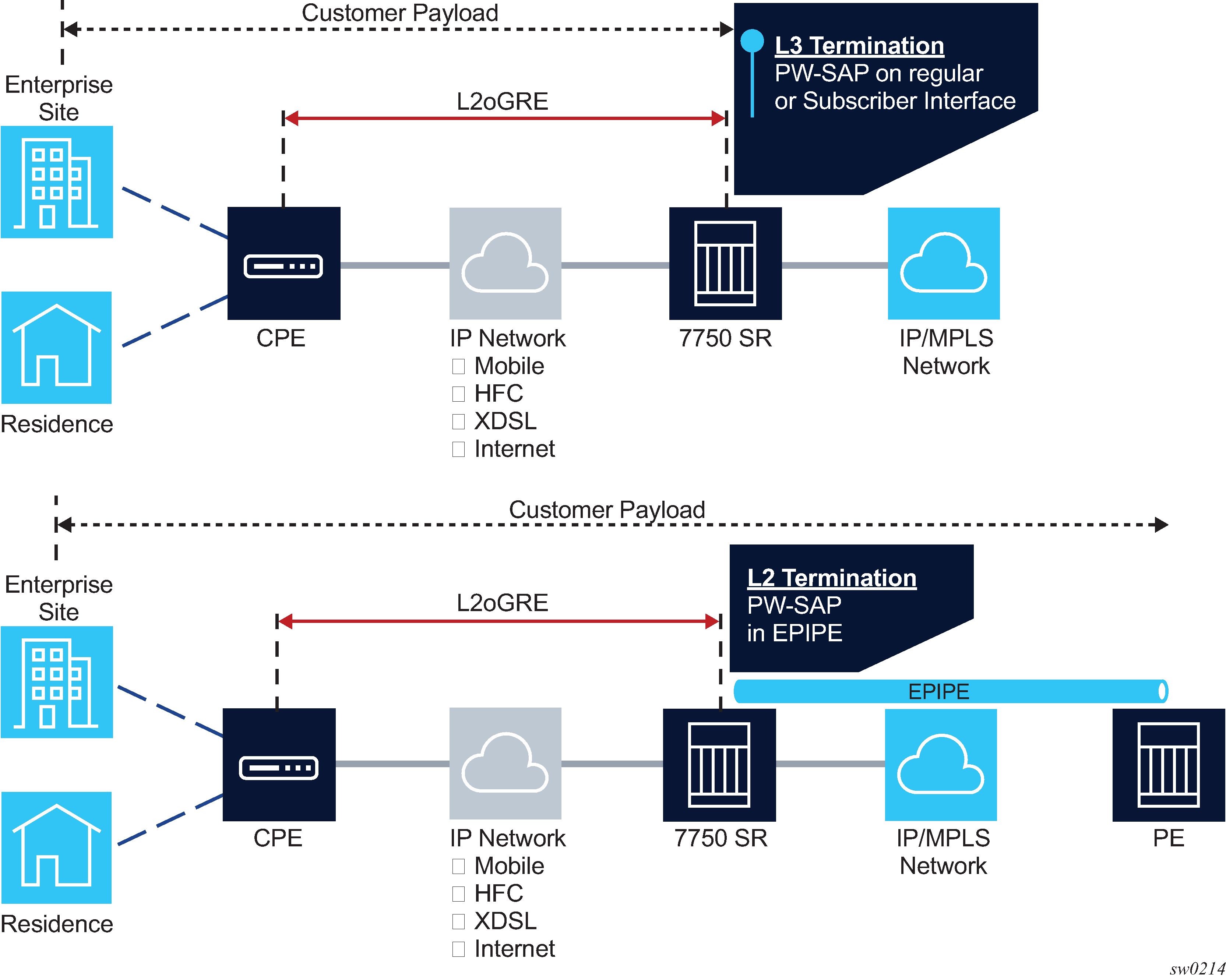
L2oGRE termination on an FPE-based PW port allows Layer 2 customer traffic to be transported over an IP network to an SR OS node deeper in the network. In the SR OS node, the customer's payload delivered within L2oGRE tunnel is extracted onto a PW SAP (configured under an interface, group interface, or Epipe) and handed off to an Layer 2 or Layer 3 service. This allows the operator to quickly and simply expand their service offering to their customers over an existing IP network. New service offerings become independent of the existing IP network to which CEs are attached.
For secure operation, the transit IPv4/IPv6 network should be trusted or alternatively, GRE traffic can be secured by IPsec (L2oGREoIPSec).
L2oGRE network examples shows a typical example where a customer payload is tunneled in GRE through an IPv4 or IPv6 network for an Layer 2 or Layer 3 handoff in an SR OS node that is placed deeper in the network.
L2oGRE packet format
The following figure shows the L2oGRE packet format.
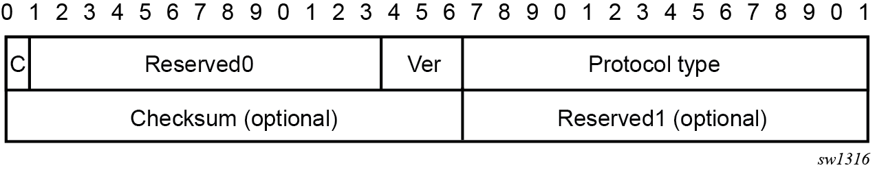
The supported GRE header in this context is defined in RFC 2784, Generic Routing Encapsulation (GRE). The protocol type is set to 0x6558 (bridged Ethernet), and the Checksum and Reserved1 fields are normally omitted. The SR OS can accept headers with those two fields present, but the system omits them when encapsulating packets on transmission. Therefore, the transmitted GRE header length in the SR OS is 4 bytes.
Key and sequence number extensions to GRE as defined in RFC 2890, Key and Sequence Number Extensions to GRE, are not supported and received packets containing key or sequence numbers are dropped in the SR.
GRE delivery protocol
The GRE delivery protocol (transport protocol) can be IPv4 or IPv6.
If the GRE delivery protocol is IPv4, then the protocol field in IPv4 header is set to value 47 (GRE). The same value (47 – GRE) is used on the Next Header field if the delivery protocol is IPv6. IPv6 extension headers in the L2oGRE transport IPv6 header are not supported, and packets containing these IPv6 extension headers are dropped.
Tracking payloads and service termination points
A customer payload within L2oGRE can be extracted onto a PW SAP inside an SR OS node. This PW SAP can be configured under an interface, subscriber interface, or an Epipe. When on a PW SAP, customer traffic can be passed further into the network to its destination using Layer 2 or Layer 3 services. End-to-end Layer 2 and Layer 3 scenarios are described in the following sections.
Plain L3 termination
L2oGRE MTUs shows an example of plain Layer 3 termination with MTUs.
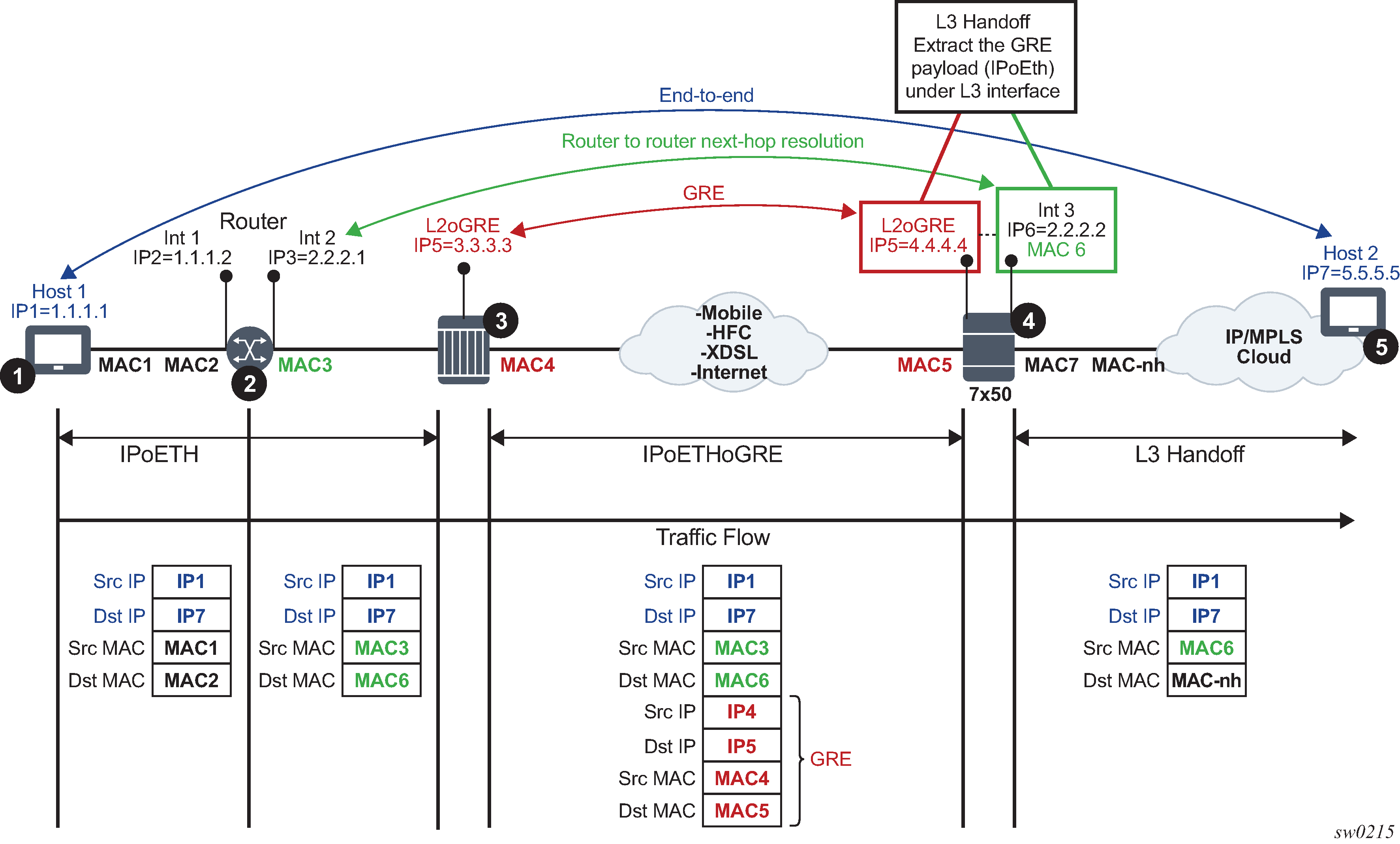
In this example:
Communication occurs between points 1 and 5.
There may be a router present at point 2. A router at point 2 would see the SR OS node as Layer 3 next-hop.
The device in point 3 encapsulates Layer 2 Ethernet frames into GRE and sends them to the SR OS node.
The SR OS node at point 4 de-encapsulates the packet and performs an Layer 3 lookup on the inner packet to deliver it to the destination.
The following is an example where PW SAP is configured under a Layer 3 interface with a PW carrying IP over Ethernet:
configure
service vprn 1 customer 1 create
interface example-if
address 192.168.1.1/24
sap pw-1:5.5 create
ingress
filter ip 1000
egress
filter ip 2000
Layer 2 termination
Layer 2 termination and hand-off shows an example of Layer 2 termination and hand-off.
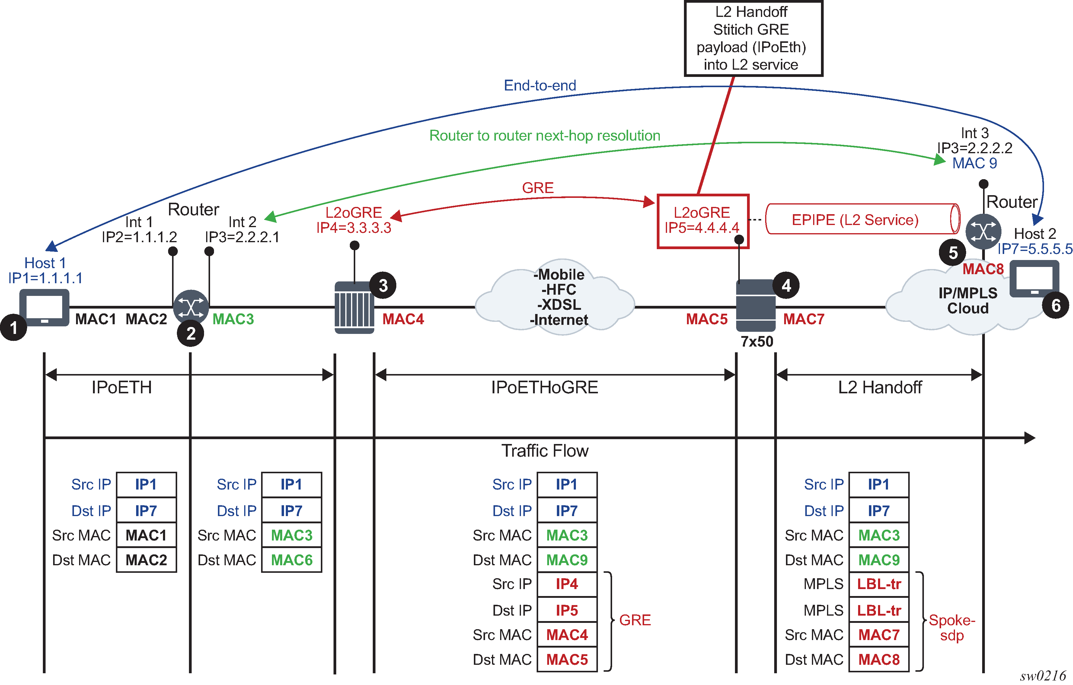
In this example:
Communication occurs between points 1 and 6.
There may be a router present at point 2. A router at point 2 would see a Layer 3 device at point 5 as a Layer 3 next-hop. Everything in between is Layer 2.
The device at point 3 encapsulates Layer 2 Ethernet frames into GRE and sends them to the SR OS node (7x50).
The SR OS node at point 4 de-encapsulates the packet and sends it into the Layer 2 service that leads to the node at point 5.
The following shows an example of PW SAP configured under an Epipe:
configure
service epipe 4 customer 1 create
sap pw-1:2 create
spoke-sdp 1:1
ESM termination
The primary case for ESM termination is business services. ESM termination shows an example of ESM termination.
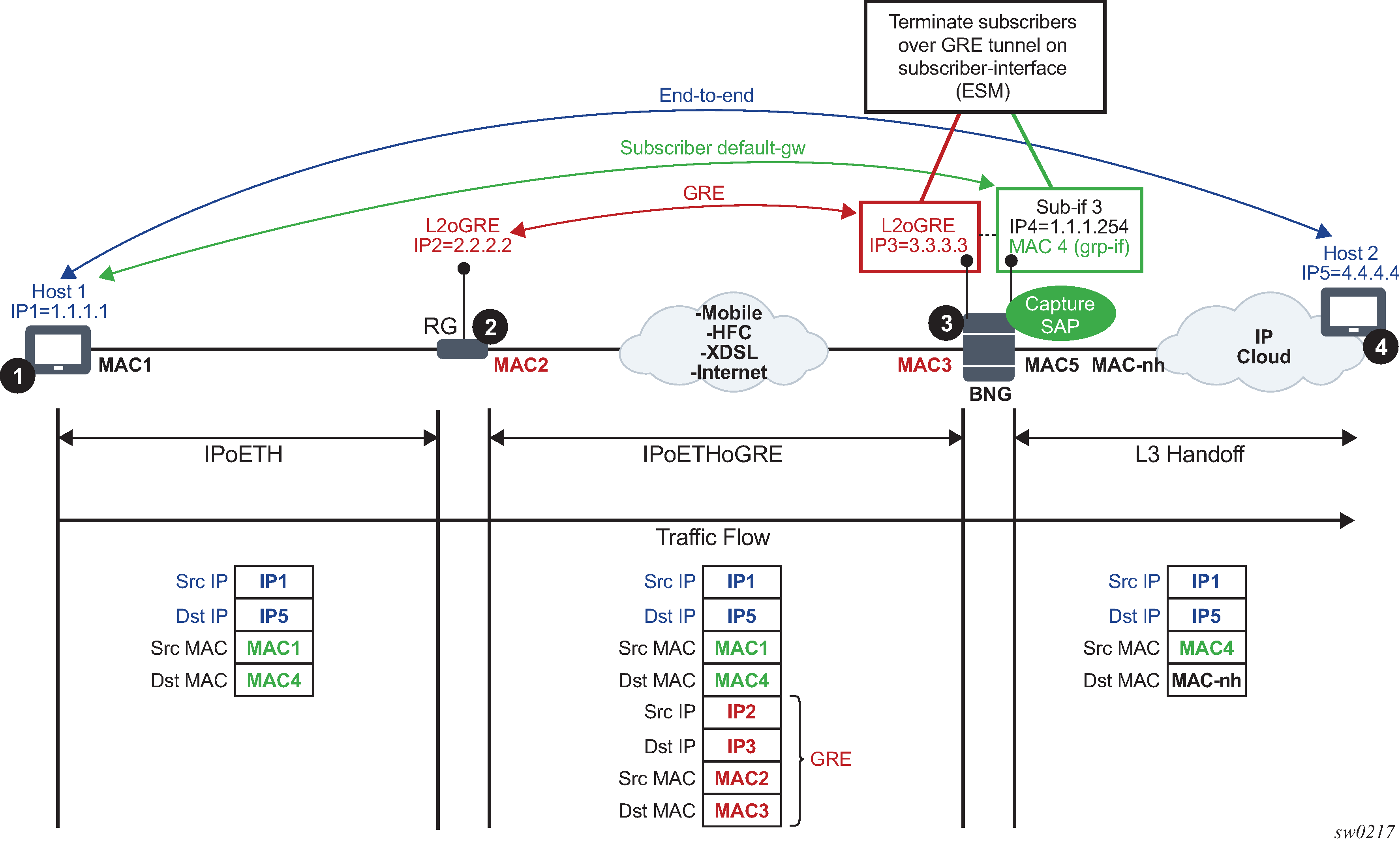
In this example:
Communication occurs between points 1 and 4.
RG (Residential Gateway) at point 2 encapsulates L2 customer frames into GRE and sends them the SR OS node (7x50 BNG).
The BNG node at point 3 terminates the subscriber traffic, performs an Layer 3 lookup, and sends it to the destination.
The following shows an example where a PW SAP is configured under a subscriber interface:
configure
service vprn 3 customer 1 create
interface subscriber-interface <sub-if-name>
address 192.168.1.1/24
group-interface  <grp-if-name>
sap pw-1:10.10 create
The following shows an example with the capture of a PW SAP configured:
configure
service vpls 2 customer 1 create
trigger-packet dhcp pppoe
sap pw-1:*.* capture-sap create
Configuration steps
L2oGRE tunnels are emulated as an SDP of type gre-eth-bridged (shown as GRE-B in the output of relevant show commands). This SDP defines two end-points on the tunnel:
far-end IP address
This defines the IP address of the remote device that terminates the tunnel.
local IP address where the tunnel is terminated within an SR OS
This is a special IP address within an SR OS node that is not associated with any interface. It is only used for L2oGRE tunnel termination.
Binding an L2oGRE tunnel to an FPE-based PW port within the SR OS is performed through an Epipe service. When the connection is established, the tunnel payload can be extracted to a PW SAP that can be used similarly to a regular SAP under Layer 3 interfaces, subscriber interfaces, or an Epipe.
L2oGRE tunnel example configuration describes the L2oGRE example configuration steps.
| Step | Example CLI | Comments |
|---|---|---|
PXC-based PW Port related configuration |
||
PW Port creation |
|
L2oGRE tunnel is terminated on this PW port. |
Port-XC creation |
|
This command triggers automatic creation of PXC sub-ports:
This is where the L2oGRE terminating PW port is anchored. |
Creation of FPE that is used for PW port anchoring |
|
The application under this FPE is the PW port termination. The use of PW port in this case is versatile and can be used to terminate an L2oGRE or MPLS/GRE-based PW. In this example, it is used to terminate an L2oGRE tunnel. |
L2oGRE tunnel definition |
||
Configuration of GRE-bridged tunnel termination IPv4/IPv6 addresses. |
|
This is a special IPv4/IPv6 address that is not configured under any Layer 3 interface and it must not overlap with any IPv4/IPv6 address configured under an Layer 3 interface in Base router. Multiple termination IPv4/IPv6 addresses are supported. |
Configuration of L2oGRE SDP |
or
|
This represents the L2oGRE tunnel within SR OS as defined by the tunnel end-point IPv4/IPv6 addresses. |
Stitching L2oGRE tunnel to an anchored PW port |
||
Association between the PW port and a PXC port via FPE. |
|
This command anchors the PW port 1 to a PXC port referenced in FPE 1. |
Binding between L2oGRE tunnel and the PW port |
|
L2oGRE is terminated on a PW port and the Layer 2 payload within the tunnel is extracted on the PW SAP |
PW SAP service association |
||
Creation of services that use PW SAP |
|
|
Fragmentation and MTU configuration
IP fragmentation is only supported for L2oGRE with IPv4 transport. Traffic is subjected to several MTU checks in the downstream direction (toward the remote end of the L2oGRE tunnel) within the SR OS node, as shown in L2oGRE MTUs.

In the example:
Port MTU represents the maximum frame size on the outgoing physical port.
IP MTU is the maximum IP packet size on the outgoing IP interface.
SDP Path MTU represents the maximum size of a frame that is encapsulated with the GRE tunnel. Its value is determined by the smallest MTU size on the path between the two GRE tunnel terminating end-points. The SDP Path MTU is calculated automatically by subtracting transport IP and GRE header bytes from the configured IP MTU of the outgoing interface.
Service MTU indicates the maximum frame size that the customer can accept over the service (PW SAP). Its value is determined by the MTU size within the customer's network. The service MTU is configured within the VC-switching Epipe that stitches the L2oGRE spoke SDP to a PW port. The default value is set to 1514 bytes.
MTU values:
ESM termination shows an example of IPv4 as the GRE delivery protocol.
Port MTU = 1600 bytes (this is operator's configured value)
IP MTU (of the outgoing interface) = 1600 bytes- 22 bytes= 1578 bytes (this is operator's configured value)
SDP Path MTU = automatically calculated and set to 1578 bytes - 24 bytes = 1554 bytes.
Service MTU = This value must be configured to a value no higher than 1554 bytes (SDP Path MTU).
Frames within an SR OS cannot be fragmented on a service or SDP level. However, L2oGRE traffic can be fragmented at the port level and for IPv4 traffic at any downstream point, if the DF bit in the IP header is cleared. The DF bit setting is controlled by the config>service>sdp>allow-fragmentation and config>service>pw-template>allow-fragmentation commands.
L2oGRE-v6 frames are subjected to the same MTU checks as IPv4 frames. However, IPv6 frames are not fragmented if their size exceeds MTU, and instead, are dropped.
Reassembly
L2oGRE reassembly for IPv4 transport is supported through a generic reassembly function that requires an MS-ISA. As fragmented traffic enters an SR OS node, it is redirected to an MS-ISA via filters. When the traffic is reassembled in the MS-ISA, it is re-inserted into the forwarding complex where normal processing continues (as if the non-fragmented traffic originally entered the node).
Configuring reassembly for GRE describes the configuration steps to support reassembly for GRE.
| Step | Example CLI | Comments |
|---|---|---|
Creation of a NAT-group that contains MS-ISAs |
|
The reassembly function is performed in a NAT group that contains one or more MS-ISAs. |
Referencing a reassembly group that is used for traffic in the Base routing context |
|
Identification of the reassembly group that is used for traffic in the Base routing context. Upon reassembly, traffic is re-inserted in the same (Base) routing context. Reassembly group ID corresponds to the NAT group ID (in this case 1). There can be multiple NAT groups (reassembly groups) configured in the system and this command identifies the reassembly group that is used in the Base routing context. |
Identifying and directing fragmented traffic to the reassembly function. |
|
Fragmented GRE traffic is identified via a filter and redirected to the reassembly function. This filter must be applied to all ingress interfaces on which GRE traffic is expected to arrive. |