Introduction
A service is a globally unique entity that refers to a type of connectivity service for either Internet or VPN connectivity. Each service is uniquely identified by a service ID and an optional service name within a service area. The Nokia service router model uses logical service entities to construct a service. In the service model, logical service entities provide a uniform, service-centric configuration, management, and billing model for service provisioning.
In the Nokia router services can provide Layer 2 bridged service or Layer 3 IP-routed connectivity between a service access point (SAP) on one router and another service access point (a SAP is where traffic enters and exits the service) on the same (local) router or another router (distributed). A distributed service spans more than one router.
Distributed services use service distribution points (SDPs) to direct traffic to another Nokia router through a service tunnel. SDPs are created on each participating router, specifying the origination address (the router participating in the service communication) and the destination address of another router. SDPs are then bound to a specific customer service. Without the binding process, far-end router is not able to participate in the service (there is no service without associating an SDP with a service).
Service types
The Nokia routers offer the following types of subscriber services which are described in more detail in the referenced chapters:
Virtual Leased Line (VLL) services
Ethernet pipe (Epipe)
This is a Layer 2 point-to-point VLL service for Ethernet frames.
IP pipe (Ipipe)
This provides 7750 SR and 7450 ESS IP connectivity between a host attached to a point-to-point access circuit (PPP) with routed IPv4 encapsulation and a host attached to an Ethernet interface.
See the 7450 ESS, 7750 SR, 7950 XRS, and VSR Layer 2 Services and EVPN Guide for more information about VLL services.
Virtual Private LAN Service (VPLS)
This is a Layer 2 multipoint-to-multipoint VPN. VPLS includes Hierarchical VPLS (H-VPLS) which is an enhancement of VPLS which extends Martini-style signaled or static virtual circuit labeling outside the fully meshed VPLS core.
See the 7450 ESS, 7750 SR, 7950 XRS, and VSR Layer 2 Services and EVPN Guide for more information about VPLS.
Internet Enhanced Service (IES)
This is a direct Internet access service where the customer is assigned an IP interface for Internet connectivity.
See the 7450 ESS, 7750 SR, 7950 XRS, and VSR Layer 3 Services Guide: IES and VPRN for more information about IES.
Virtual Private Routed Network (VPRN)
This is a Layer 3 IP multipoint-to-multipoint VPN service as defined in RFC 2547bis.
See the 7450 ESS, 7750 SR, 7950 XRS, and VSR Layer 3 Services Guide: IES and VPRN for more information about VPRN services.
Circuit Emulation Service (Cpipe)
7750 SR circuits encapsulated in MPLS use circuit pipes (Cpipes) to connect to the far end circuit. Cpipes support either SAP-spoke SDP or SAP-SAP connections.
Service policies
Common to all Nokia service router connectivity services are policies that are assigned to the service. Policies are defined at a global level and then applied to a service on the router. Policies are used to define Nokia service router service enhancements. The types of policies that are common to the router’s connectivity services are:
SAP Quality of Service (QoS) policies
SAP QoS policies allow for different classes of traffic within a service at SAP ingress and SAP egress. QoS ingress and egress policies determine the QoS characteristics for a SAP. A QoS policy applied to a SAP specifies the number of queues, queue characteristics (such as forwarding class, committed, and peak information rates, and so on) and the mapping of traffic to a forwarding class. A QoS policy must be created before it can be applied to a SAP. A single ingress and a single egress QoS policy can be associated with a SAP.
filter policies
Filter policies allow for selective blocking of traffic matching criteria from ingressing or egressing a SAP. Filter policies, also referred to as access control lists (ACLs), control the traffic allowed in or out of a SAP based on MAC or IP match criteria. Associating a filter policy on a SAP is optional. Filter policies are identified by a unique filter policy ID. A filter policy must be created before it can be applied to a SAP. A single ingress and single egress filter policy can be associated with a SAP.
scheduler policies
Scheduler policies define the hierarchy and operating parameters for virtual schedulers. Schedulers are divided into groups based on the tier each scheduler is created under. A tier is used to give structure to the schedulers within a policy and define rules for parent scheduler associations.
accounting policies
Accounting policies define how to count the traffic usage for a service for billing purposes. The routers provide a comprehensive set of service-related counters. Accounting data can be collected on a per-service, per-forwarding class basis, which enables network operators to accurately measure network usage and bill each customer for each individual service using any of a number of different billing models.
Multipoint shared queuing
Multipoint shared queuing is supported only on Nokia service router routers.
Multipoint shared queuing is supported to minimize the number of multipoint queues created for ingress VPLS, IES or VPRN SAPs or ingress subscriber SLA profiles. Normally, ingress multipoint packets are handled by multipoint queues created for each SAP or subscriber SLA profile instance. In some instances, the number of SAPs or SLA profile instances are sufficient for the in use multipoint queues to represent many thousands of queues on an ingress forwarding plane. If multipoint shared queuing is enabled for the SAPs or SLA profile instances on the forwarding plane, the multipoint queues are not created. Instead, the ingress multipoint packets are handled by the unicast queue mapped to the forwarding class of the multipoint packet.
Functionally, multipoint shared queuing is a superset of shared queuing. With shared queuing on a SAP or SLA profile instance, only unicast packets are processed twice, once for the initial service level queuing and a second time for switch fabric destination queuing. Shared queuing does not affect multipoint packet handling. Multipoint packet handling in normal (service queuing) is the same as shared queuing. When multipoint shared queuing is enabled, shared queuing for unicast packets is automatically enabled.
Ingress queuing modes of operation
Three modes of ingress SAP queuing are supported for multipoint services (IES, VPLS and VPRN); service, shared, and multipoint shared. The same ingress queuing options are available for IES and VPLS subscriber SLA profile instance queuing.
Ingress service queuing
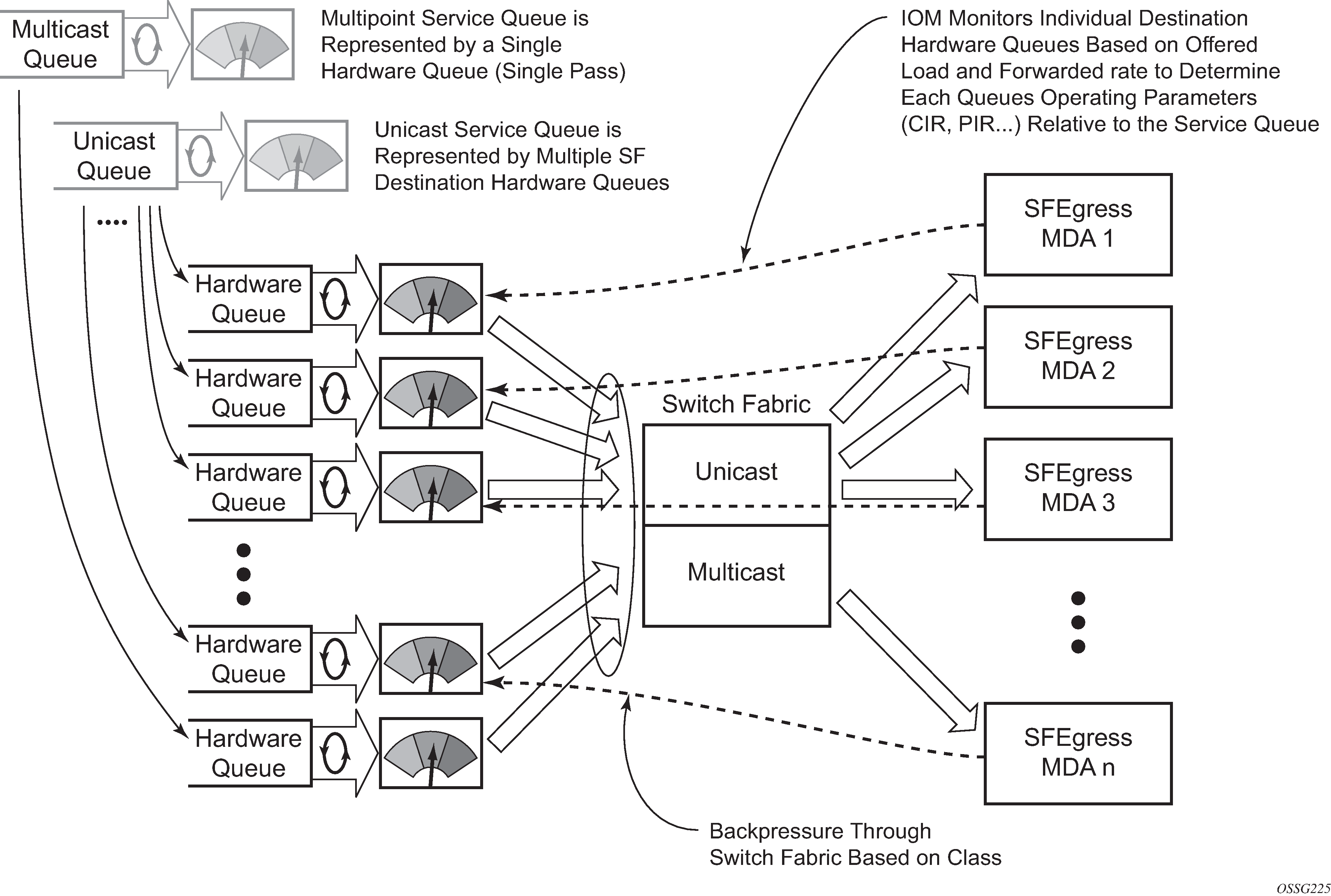
Normal or service queuing is the default mode of operation for SAP ingress queuing. Service queuing preserves ingress forwarding bandwidth by allowing a service queue defined in an ingress SAP QoS policy to be represented by a group of hardware queues. A hardware queue is created for each switch fabric destination to which the logical service queue must forward packets. For a VPLS SAP with two ingress unicast service queues, two hardware queues are used for each destination forwarding engine the VPLS SAP is forwarding to. If three switch fabric destinations are involved, six queues are allocated (two unicast service queues multiplied by three destination forwarding complexes equals six hardware queues). Unicast service queue mapping to multiple destination based hardware queues demonstrates unicast hardware queue expansion. Service multipoint queues in the ingress SAP QoS policy are not expanded to multiple hardware queues, each service multipoint queue defined on the SAP equates to a single hardware queue to the switch fabric.
When multiple hardware queues represent a single logical service queue, the system automatically monitors the offered load and forwarding rate of each hardware queue. Based on the monitored state of each hardware queue, the system imposes an individual CIR and PIR rate for each queue that provides an overall aggregate CIR and PIR reflective of what is provisioned on the service queue.
Ingress shared queuing
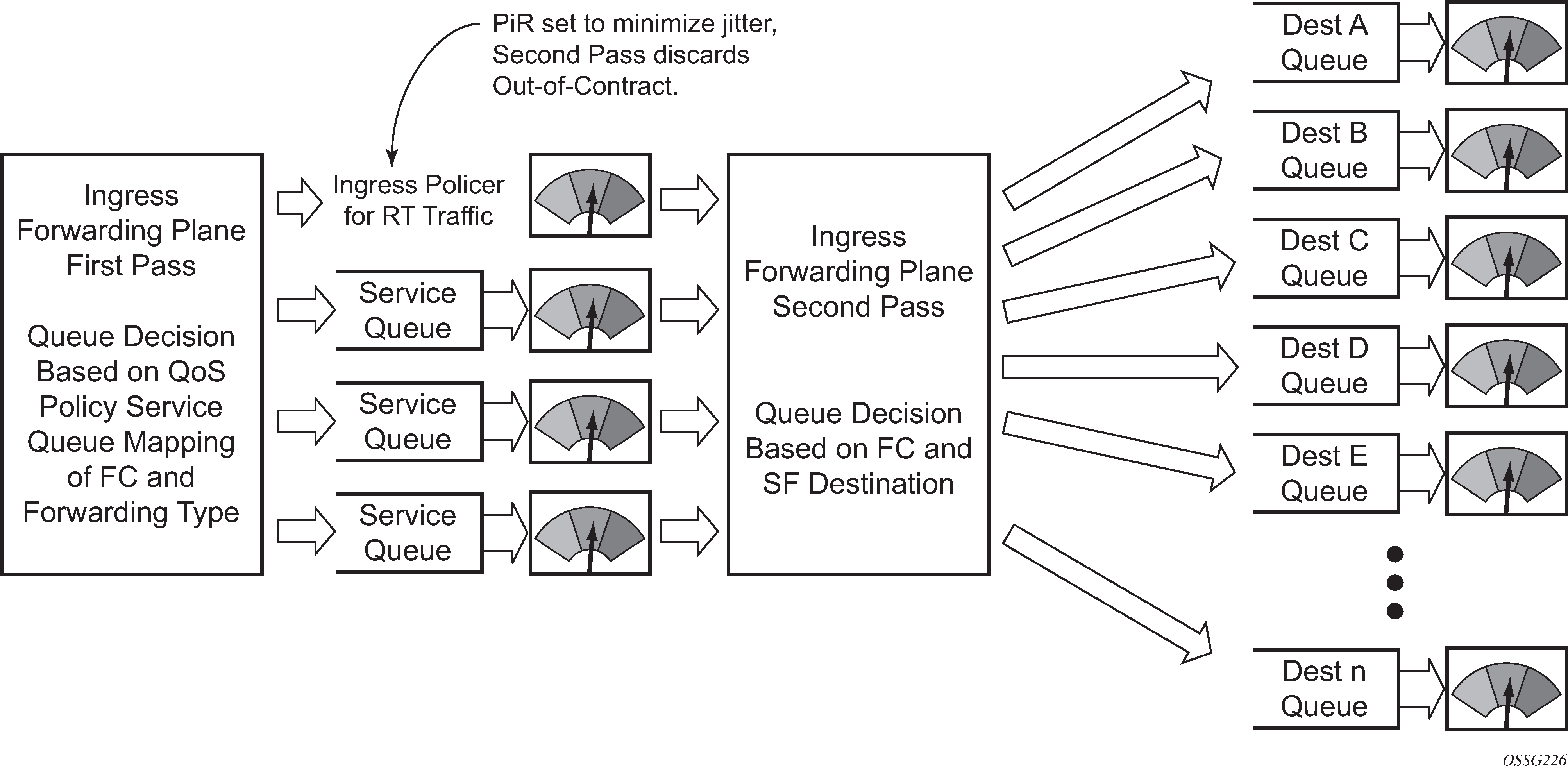
To avoid the hardware queue expansion issues associated with normal service based queuing, the system allows an ingress logical service queue to map to a single hardware queue when shared queuing is enabled. Shared queuing uses two passes through the ingress forwarding plane to separate ingress per service queuing from the destination switch fabric queuing. In the case of shared queuing, ingress unicast service queues are created one-for-one relative to hardware queues. Each hardware queue representing a service queue is mapped to a special destination in the traffic manager that ‛forwards’ the packet back to the ingress forwarding plane allowing a second pass through the traffic manager. In the second pass, the packet is placed into a ‛shared’ queue for the destination forwarding plane. The shared queues are used by all services configured for shared queuing.
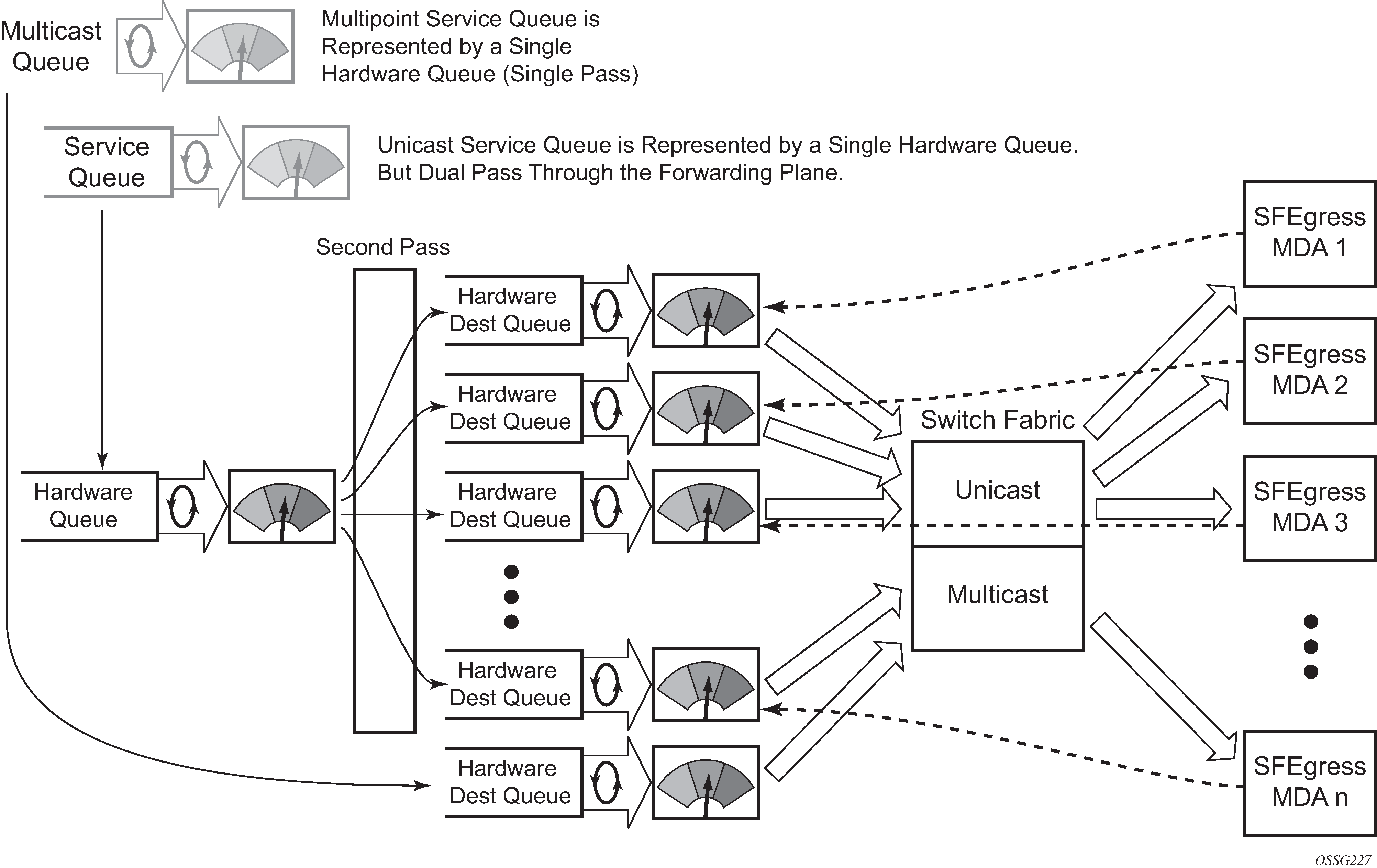
When the first SAP or SLA profile instance is configured for shared queuing on an ingress forwarding plane, the system allocates eight hardware queues per available destination forwarding plane, one queue per forwarding class. Twenty four hardware queues are also allocated for multipoint shared traffic. The shared queue parameters that define the relative operation of the forwarding class queues are derived from the Shared Queue policy defined in the QoS CLI node. Unicast service queuing with shared queuing enabled demonstrates shared unicast queuing. SAP or SLA profile instance multipoint queuing is not affected by enabling shared queuing. Multipoint queues are still created as defined in the ingress SAP QoS policy and ingress multipoint packets only traverse the ingress forwarding plane a single time, as demonstrated in Multipoint queue behavior with shared queuing enabled.
Enabling shared queuing may affect ingress performance because of double packet processing through the service and shared queues.
Ingress multipoint shared queuing
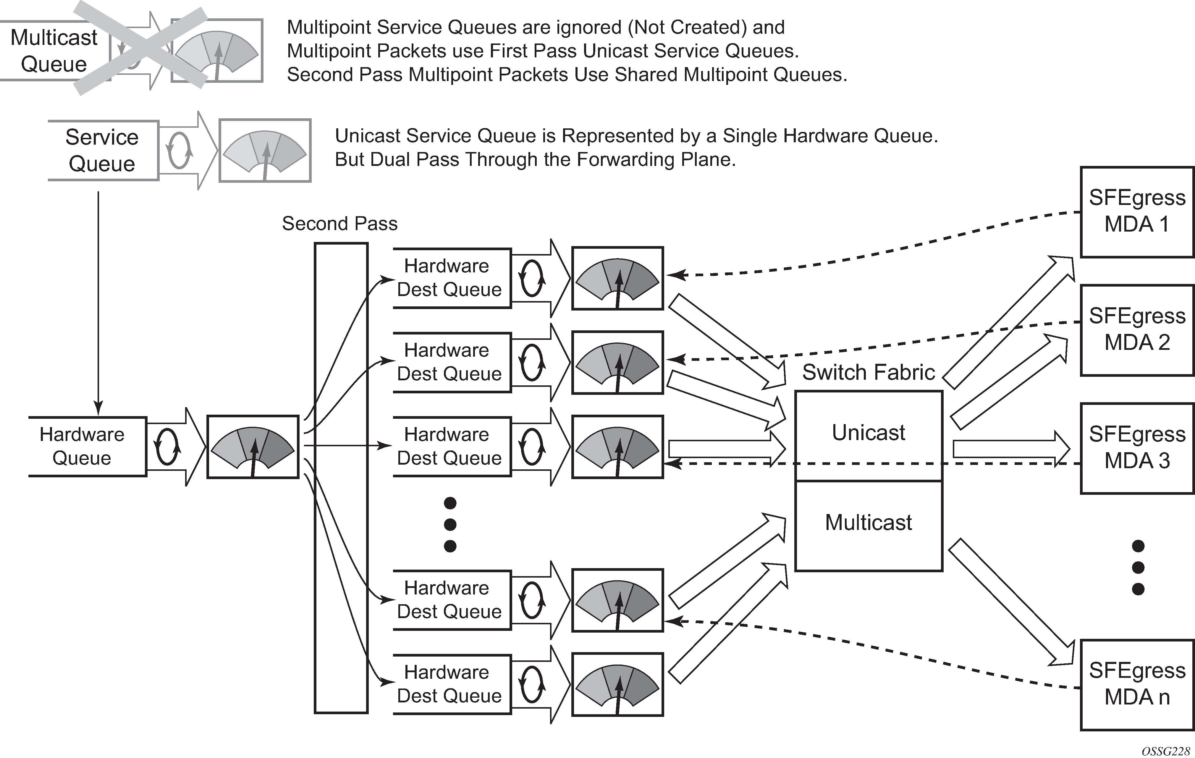
Ingress multipoint shared queuing is a variation to the unicast shared queuing defined in Ingress shared queuing. Ingress unicast service queues are mapped one-for-one with hardware queues and unicast packets traverse the ingress forwarding plane twice. In addition to the above, the multipoint queues defined in the ingress SAP QoS policy are not created. Instead, multipoint packets (broadcast, multicast and unknown unicast destined) are treated to the same dual pass ingress forwarding plane processing as unicast packets. In the first pass, the forwarding plane uses the unicast queue mappings for each forwarding plane. The second pass uses the multipoint shared queues to forward the packet to the switch fabric for special replication to all egress forwarding planes that need to process the packet.
The benefit of defining multipoint shared queuing is the savings of the multipoint queues per service. By using the unicast queues in the first pass and then the aggregate shared queues in the second pass, per service multipoint queues are not required. The predominate scenario where multipoint shared queuing may be required is with subscriber managed QoS environments using a subscriber per SAP model. Usually, ingress multipoint traffic is minimal per subscriber and the extra multipoint queues for each subscriber reduces the overall subscriber density on the ingress forwarding plane. Multipoint shared queuing eliminates the multipoint queues sparing hardware queues for better subscriber density. Multipoint shared queuing using first pass unicast queues demonstrates multipoint shared queuing.
One disadvantage of enabling multipoint shared queuing is that multipoint packets are no longer managed per service (although the unicast forwarding queues may provide limited benefit in this area). Multipoint packets in a multipoint service (VPLS, IES and VPRN) use significant resources in the system, consuming ingress forwarding plane multicast bandwidth and egress replication bandwidth. Usually, the per service unicast forwarding queues are not rate limited to a degree that allows adequate management of multipoint packets traversing them when multipoint shared queuing is enabled. It is possible to minimize the amount of aggregate multipoint bandwidth by setting restrictions on the multipoint queue parameters in the QoS node’s shared queue policy. Aggregate multipoint traffic can be managed per forwarding class for each of the three forwarding types (broadcast, multicast or unknown unicast – broadcast and unknown unicast are only used by VPLS).
A second disadvantage to multipoint shared queuing is the fact that multipoint traffic now consumes double the ingress forwarding plane bandwidth because of dual pass ingress processing.