NGE
This section provides information to configure network group encryption (NGE) on the VSR.
NGE overview
The network group encryption (NGE) feature enables end-to-end encryption of MPLS services, Layer 3 user traffic, and IP/MPLS control traffic. NGE is an encryption method that uses a group-based keying security architecture, which removes the need to configure individual encryption tunnels to achieve network-wide encryption.
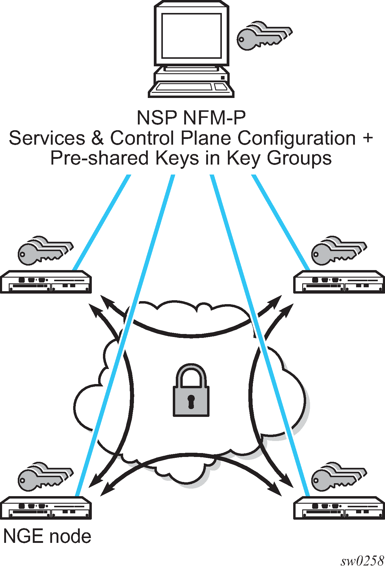
NGE relies on the NSP NFM-P to manage the network and apply encryption to specific MPLS services, Layer 3 user traffic, or control plane traffic depending on the security requirements of the network. Operators designate traffic types that require added security and then apply NGE to those traffic types using the NSP NFM-P. The NSP NFM-P also acts as the network-wide NGE key manager, downloading encryption and authentication keys to nodes and performing hitless rekeying of the network at operator-defined intervals. For more information about managing NGE within a network, see the NSP NFM-P User Guide.
NGE network with NSP NFM-P management shows an NGE network with NSP NFM-P services, control plane configuration, and key management.
NGE provides five main types of encryption to secure an IP/MPLS network:
SDP encryption
This is MPLS user plane encryption enabled on MPLS tunnels (SDPs) supporting VPRN or IES services using spoke SDPs, VPLS using spoke or mesh SDPs, routed VPLS into VPRN, Epipes, and Cpipes.
VPRN encryption
unicast VPRN
This is MP-BGP-based VPRN-level encryption using auto-bind of LDP, GRE, RSVP-TE, MPLS (LDP or RSVP-TE), or segment routing (SR-ISIS, SR-OSPF, and SR-TE) tunnels.
multicast VPRN
NG-mVPN using mLDP with auto-discovery
router interface
This is Layer 3 user plane and control plane encryption.
WLAN-GW group interface
This is L2oMPLSoGRE level encryption from WLAN access points (APs) that support NGE.
PW template encryption
This is BGP-VPLS- and BGP-VPWS-based MPLS services encryption, which uses a PW template with auto-gre-sdp configured.
NGE is supported on the following platforms:
VSR-I
VSR-a
WLAN-GW group interfaces enabled with NGE is further supported on the following platforms:
7750 SR-7
7750 SR-12
7750 SR-12e
7750 SR-1e
7750 SR-2e
7750 SR-3e
NGE key groups and encryption partitions
NGE allows a tiered approach to managing encryption keys in a network using key groups by configuring services or router interfaces to use specific key groups, depending on security policies for the service and network topology.
Key group partitioning shows a typical application of NGE key group partitioning in which there are several critical levels (tiers) of security that need to be considered. In this example, the protection of Distribution Automation and Field Area Network (DA/FAN) equipment are less critical than the Transmission or Distribution Substation network equipment. Ensure that nodes more at risk of a security breach do not contain more critical information than is necessary. Therefore, encryption keys for the sensitive portions of the network (such as control center traffic) should not be available on nodes that are at risk. The NGE feature enables operators to partition and distribute encryption keys among different services, NGE domains, or nodal groups in a network. NGE partitions are enabled by configuring different key groups per security partition and applying those key groups as needed.
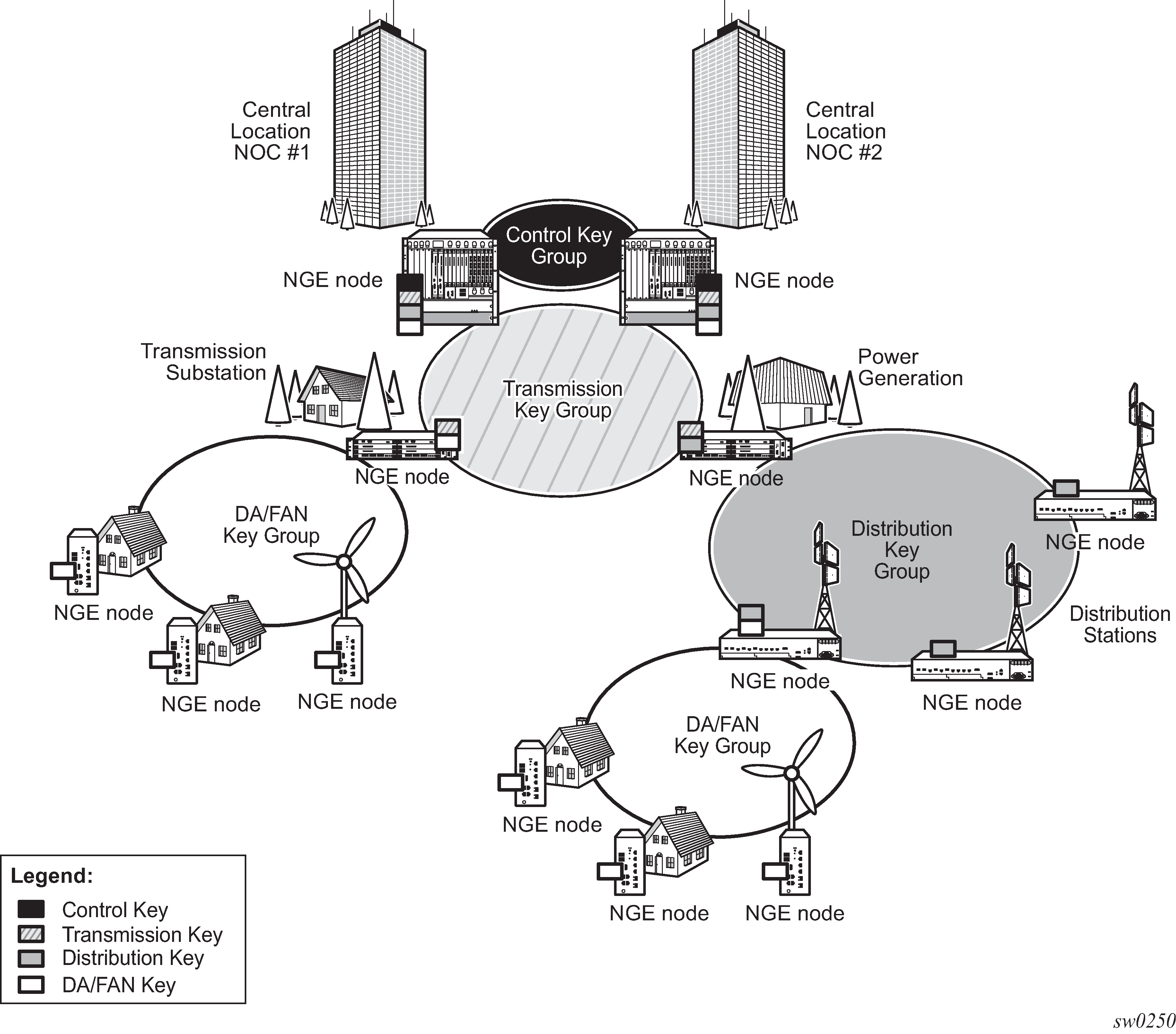
Another application of key group partitioning allows different parts of an organization to have their own method of end-to-end communication without the need to share encryption keys between each organization. If two partitions need to communicate between themselves, gateway nodes configured with both key groups allow inter-organization traffic flows between the key group partitions as needed.
Network services platform management
The NGE feature is tightly integrated with the NSP NFM-P. The following functions are provided by the NSP NFM-P :
managing and synchronizing encryption and authentication keys within key groups on a network-wide basis
configuring NGE on MPLS services and managing associated key groups
configuring NGE on router interfaces and managing associated key groups
coordinating network-wide rekeying of key groups
The NSP NFM-P acts as the key manager for NGE-enabled nodes and allocates the keys in key groups that are used to perform encryption and authentication. The NSP NFM-P ensures that all nodes in a key group are kept in synchronization and that only the key groups that are relevant to the associated nodes are downloaded with key information.
The NSP NFM-P performs network-wide hitless rekeying for each key group at the rekeying interval specified by the operator. Different key groups can be rekeyed at different times if needed, or all key groups can be rekeyed network-wide at the same time.
For more information about NSP NFM-P management, see the ‟Service Management” section in the NSP NFM-P User Guide.
Key groups
Users can partition the network based on security requirements by organizing encryption keys into distinct key groups. A key group contains the following elements:
an encryption algorithm (see Key group algorithms)
an authentication algorithm (see Key group algorithms)
a list of security associations (SAs) (see Security associations)
an active outbound SA (see Active outbound SA)
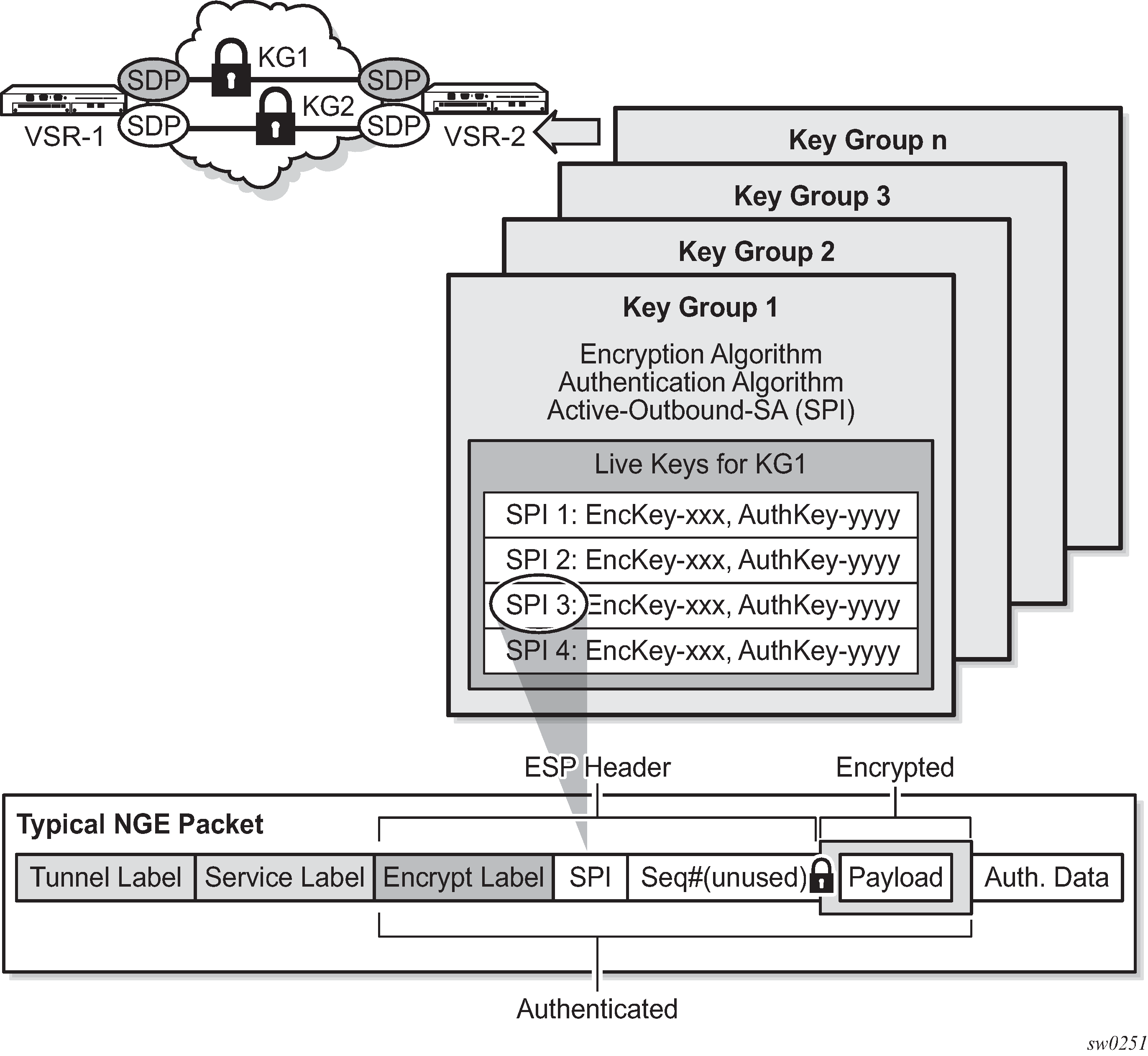
Key groups and a typical NGE packet illustrates the use of key groups (KGs), SAs, and security parameter indexes (SPIs). The VSR-1 and VSR-2 both have the same set of key groups configured. One path uses key group 1 (KG1) and the other uses key group 2 (KG2). Each key group contains the elements listed above. KG1 has four live keys, SPI_1 through SPI_4, and SPI_3 is the active outbound SA. The active outbound SA is identified by its SPI, and this SPI is embedded in the NGE packet.
Each SA listed in a key group, indexed by an SPI, specifies a single key for encryption and a single key for authentication. Packets transmitted or received that reference a particular SPI use the keys in the SA for that SPI when performing encryption and authentication.
Before enabling encryption, key groups must be configured on the node. Only after a key group is configured can it be assigned to an SDP or VPRN services.
Key group algorithms
All SAs configured in a key group share the same encryption algorithm and the same authentication algorithm. The size and values required by a particular key depend on the requirements of the algorithms selected (see lists below). One encryption algorithm and one authentication algorithm must be selected per key group.
Encryption algorithms available per key group include:
AES128 (a 128-bit key, requiring a 32-digit ASCII hexadecimal string)
AES256 (a 256-bit key, requiring a 64-digit ASCII hexadecimal string)
Authentication algorithms available per key group include:
HMAC-SHA-256 (a 256-bit key, requiring a 64-digit ASCII hexadecimal string)
HMAC-SHA-512 (a 512-bit key, requiring a 128-digit ASCII hexadecimal string)
Encryption and authentication strengths can be mixed depending on the requirements of the application. For example, 256-bit strength encryption can be used with 512-bit strength authentication.
The configured algorithms cannot be changed when there is an existing SA configured for the key group. All SAs in a key group must be deleted before a key group algorithm can be modified.
Key values are not visible in CLI or retrievable using SNMP. Each node calculates a 32-bit CRC checksum for the keys configured against the SPI. The CRC can be displayed in the CLI or read by SNMP. The purpose of the CRC is to provide a tool to check consistency between nodes, thereby verifying that each node is set with the same key values while keeping the actual key values hidden.
Encapsulating security payload
The NGE feature uses the Encapsulating Security Payload (ESP) protocol according to IETF RFC 4303. ESP maintains data integrity, ensuring privacy and confidentiality for encrypted traffic.
The ESP protocol used by NGE relies on symmetric ciphers, meaning that the same key is used for encryption and decryption. The NGE node supports Cipher Block Chaining (CBC) encryption mode. Block ciphers used by NGE include:
AES128 with a 128-bit key using 128-bit blocks
AES256 with a 256-bit key using 128-bit blocks
For authentication, the integrity check value (ICV) size is as follows:
HMAC-SHA-256 (16 bytes or 128 bits)
HMAC-SHA-512 (32 bytes or 256 bits)
Security associations
Each key group has a list of up to four security associations (SAs). An SA is a reference to a pair of encryption and authentication keys that are used to decrypt and authenticate packets received by the node and to encrypt packets leaving the node.
For encrypted ingress traffic, any of the four SAs in the key group can be used for decryption if there is a match between the SPI in the traffic and the SPI in the SA. For egress traffic, only one of the SAs can be used for encryption and is designated as the active outbound SA. Key groups and a typical NGE packet illustrates these relationships.
As shown in Key groups and a typical NGE packet , each SA is referenced by an SPI value, which is included in packets during encryption and authentication. SPI values must be numerically unique throughout all SAs in all key groups. If an SPI value is configured in one key group and an attempt is made to configure the same SPI value in another key group, the configuration is blocked.
Active outbound SA
The active outbound SA is specified by the SPI referencing the specific SA used to encrypt and authenticate packets egressing the node for the SDP or service using the key group. The SPI value for the active outbound SA is included in the ESP header of packets being encrypted and authenticated.
Services encryption
NGE provides the ability to encrypt MPLS services using key groups that are configured against these services. These services include:
VLL service (Epipe and Cpipe)
VPRN service using Layer 3 spoke SDP termination
IES service using Layer 3 spoke SDP termination
VPLS service using spoke and mesh SDPs
routed VPLS service into a VPRN or IES
MP-BGP-based VPRNs
L2oMPLSoGRE VLL service terminating on a WLAN-GW group interface
BGP-VPLS and BGP-VPWS using a PW template with auto-gre-sdp configured
NG-MVPN
For services that use SDPs, all tunnels may be either MPLS LSPs (RSVP-TE, LDP, or static LSP), or GRE or MPLSoUDP tunnels.
For MP-BGP services, resolving routes using spoke SDPs (spoke-sdp) or auto-bind SDPs (auto-bind-tunnel) is supported using LDP, GRE, RSVP-TE, or segment routing (SR-ISIS, SR-OSPF, or SR-TE).
Services encryption overview
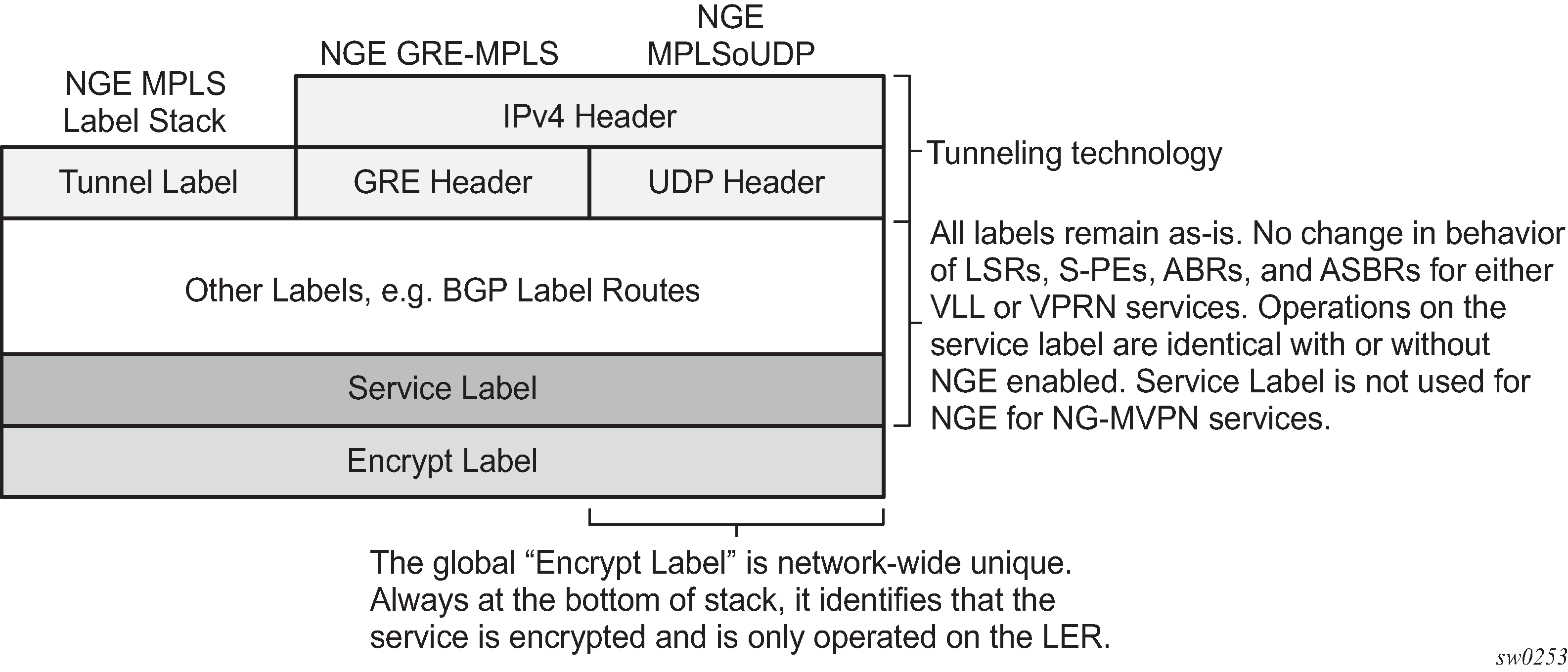
NGE adds a global encryption label to the label stack for encrypting MPLS services. The global encryption label must be a unique network-wide label; in other words, the same label must be used on all nodes in the network that require NGE services. The label must be configured on individual nodes before NGE can become operational on those nodes.
The global encryption label is used to identify packets that have an NGE-encrypted payload and is added to the bottom of the stack. This allows network elements such as LSRs, ABRs, ASBRs, and RRs to forward NGE packets without needing to understand NGE or to know that the contents of these MPLS packets are encrypted. Only when a destination PE receives a packet that needs to be understood at the service layer does the PE check for an encryption label, and then decrypt the packet.
After the global encryption label is set, it should not be changed. If the label must be changed without impacting traffic, all key groups in the system should first be deleted. Next, the label should be changed, and then all key groups should be reconfigured.
The NSP NFM-P helps to coordinate the distribution of the global encryption label and ensures that all nodes in the network are using the same global encryption label.
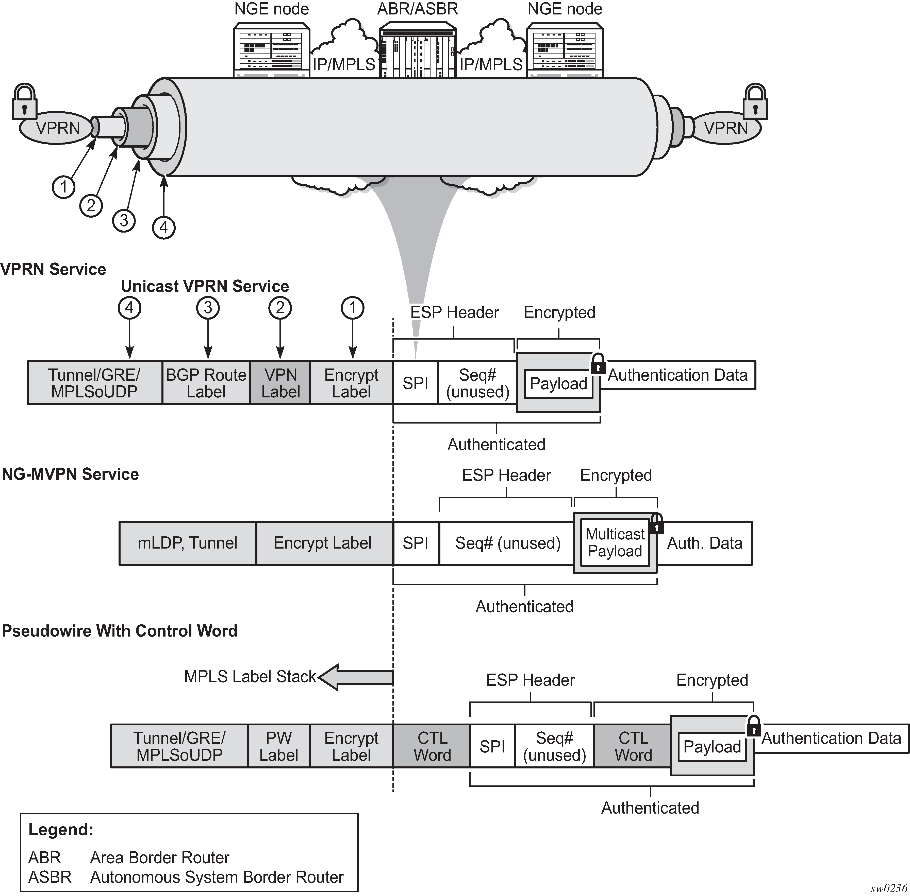
NGE MPLS/GRE/MPLSoUDP label stack illustrates the NGE MPLS, GRE, or MPLSoUDP label stack.
NGE and packet formats illustrates VPRN and PW (with control word) packet formats using NGE.
Assigning key groups to services
Assigning key groups to services requires configuring an inbound and outbound key group for directional processing on a per-service basis (see Inbound and outbound key group assignments).
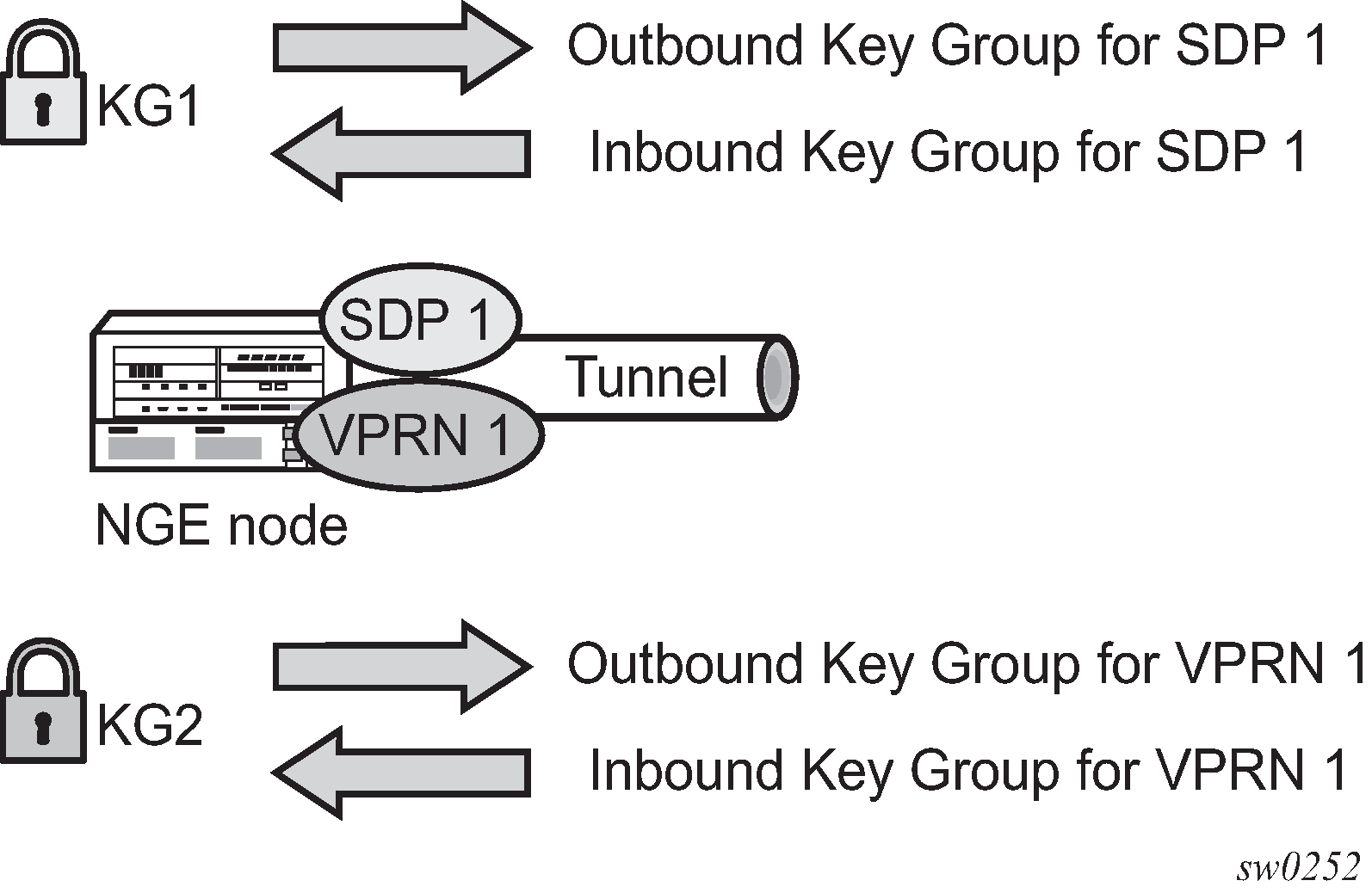
The outbound key group identifies which key group to use for traffic that egresses the node for the service. The inbound key group ensures that ingress traffic is using the correct key group for the service.
If the inbound key group is not set, the node ensures that packets are either unencrypted or are using one of the valid key groups configured in the system.
In most deployment scenarios, the inbound and outbound key groups are identical; however, it is possible to configure different key groups as the outbound and the inbound key groups, as this is not checked by the node.
Including an inbound and outbound direction when assigning key groups to services allows users to:
gracefully enable and disable NGE for services
move services from one key group domain to another domain without halting encryption
The NGE feature makes use of the NSP NFM-P to help manage the assignment of key groups to services on a network-wide basis. See the NSP NFM-P User Guide for more information.
VPRN Layer 3 spoke SDP encryption and MP-BGP-based VPRN encryption interaction
The encryption configured on an SDP used to terminate the Layer 3 spoke SDP of a VPRN always overrides any VPRN-level configuration for encryption.
When VPRN encryption is enabled, all routes resolved using MP-BGP (either with spoke SDPs using spoke-sdp or auto-bind SDPs using auto-bind-tunnel) are encrypted or decrypted using the VPRN key group.
When Layer 3 spoke SDP encryption is enabled, all routes resolved using the Layer 3 interface are encrypted or decrypted using the SDP's key group.
Some examples are as follows:
If a VPRN is enabled for encryption while a Layer 3 spoke SDP for the same VPRN is using an SDP that is not enabled for encryption, then traffic egressing the spoke SDP is not encrypted.
If a VPRN is disabled for encryption while a Layer 3 spoke SDP for the same VPRN is using an SDP that is enabled for encryption, then traffic egressing the spoke SDP is encrypted.
If a VPRN is enabled for encryption using key group X, while a Layer 3 spoke SDP for the same VPRN is using key group Y, then traffic egressing the spoke SDP is encrypted using key group Y.
The commands used for these scenarios are config>service>sdp>encryption-keygroup and config>service>vprn>encryption-keygroup.
L2 Service encryption using PW templates
NGE encryption-keygroup configuration is supported on PW templates to enable the encryption of MPLS services that are based on BGP-VPLS and BGP-VPWS and that have auto-gre-sdp enabled on the PW template. All services configured using the PW template that have both NGE and auto-gre-sdp enabled are encrypted.
When changing the encryption-keygroup on a PW template, the change does not take effect immediately. The operator must execute the following command after each change to the encryption-keygroup for it to take effect:
tools>perform>service>eval-pw-template>allow-service-impact
Pseudowire switching for NGE traffic
For VLL services, the NGE node supports PW switching of encrypted traffic from one PW to another. There are three scenarios that are supported with regard to PW switching of traffic:
PW switch using the same key group
When a PW is using an encrypted SDP, the PW may be switched to another PW that is also using an encrypted SDP, where both SDPs are in the same key group. In this case, to perform the PW switch, the NGE node leaves the encrypted payload unchanged and swaps the labels as needed for passing traffic between PWs.
PW switch using different key groups
When a PW is using an encrypted SDP, the PW may be switched to another PW that is also using an encrypted SDP, where both SDPs are in different key groups. In this case, the NGE node decrypts the traffic from the first SDP by using the configured key group for that SDP, and then re-encrypts the traffic by using the egress SDP's key group egress SPI ID.
PW switch between an encrypted and unencrypted PW
When traffic is switched from an encrypted PW to an unencrypted PW, the traffic is decrypted before it is sent. The converse occurs in the reverse direction (that is, traffic from an unencrypted PW to an encrypted PW gets encrypted before it is sent).
See ‟Pseudowire Switching” in the 7450 ESS, 7750 SR, 7950 XRS, and VSR OAM and Diagnostics Guide for more information.
Pseudowire control word for NGE traffic
The control word is a configurable option for PWs and is included in PW packets when it is configured. When control-word is enabled and NGE is used, the datapath creates two copies of the CW. One CW is both encrypted and authenticated, and is inserted after the ESP header. The other CW is not encrypted (clear form) and is inserted before the ESP header.
For cases where PW switching is configured, the NGE node ensures—in the CLI and with SNMP—that both segments of the PW have consistent configuration of the control word when encryption is being used.
WLAN-GW encryption
NGE is supported on the WLAN-GW to provide encryption of traffic to and from WLAN APs that support NGE, such as the 7705 SAR-Hm. As shown in Terminating NGE-protected WLAN AP traffic destined for the WLAN-GW, the application uses Epipe pseudowire services, as described in Pseudowire switching for NGE traffic and Pseudowire control word for NGE traffic, with L2oMPLSoGRE transport and NGE applied to the GRE-SDP.
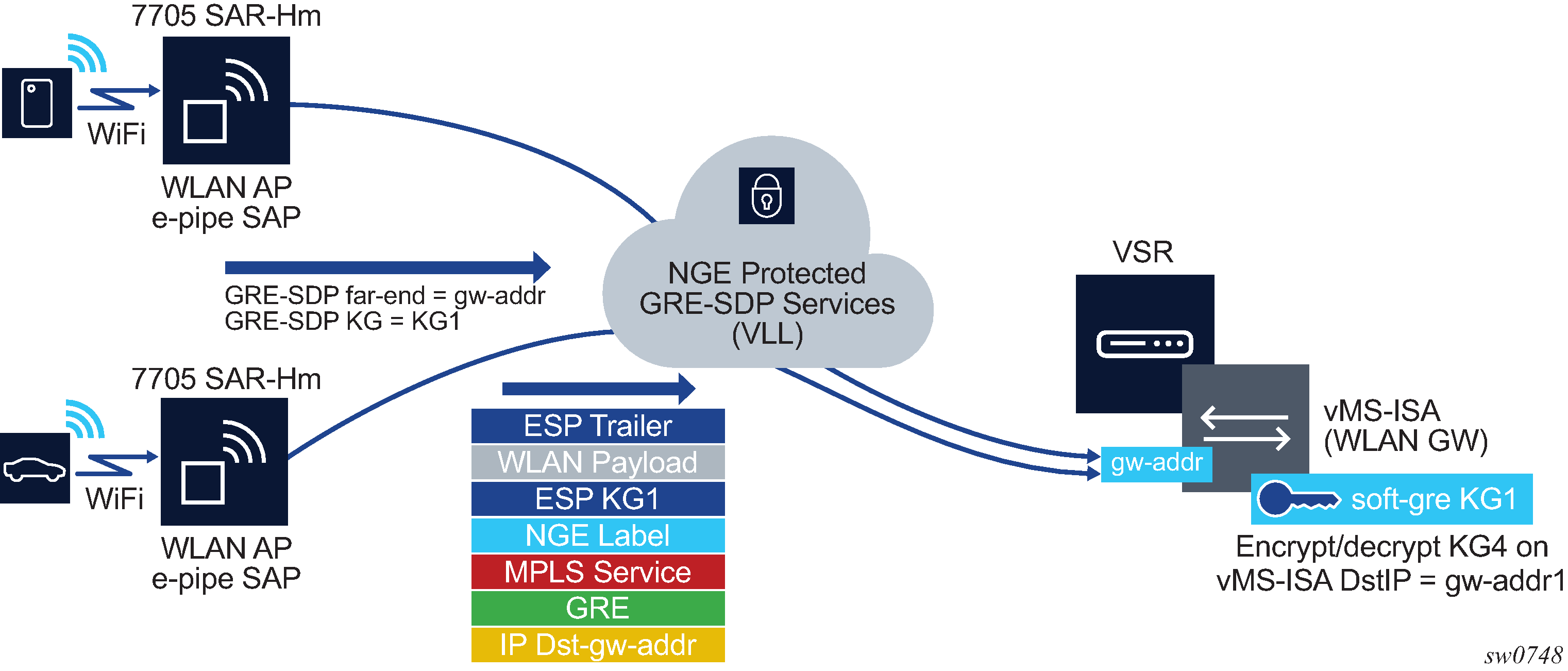
In Terminating NGE-protected WLAN AP traffic destined for the WLAN-GW, the same key group, KG1, is configured on:
the WLAN-GW gw-address under the IES or VPRN soft-GRE group interface for the vMS-ISA
the GRE SDPs that are bound to any WLAN AP Epipes that are terminating soft-GRE services on the WLAN-GW group interface
Traffic from an authenticated user on the SAR-Hm WLAN AP is encrypted and an NGE label is added to the packet after the Epipe service label. The packet format is shown in Terminating NGE-protected WLAN AP traffic destined for the WLAN-GW.
The WLAN-GW group interface is configured with the same inbound and outbound key group as the GRE-SDP used for the Epipe from the WLAN AP. Any L2oMPLSoGRE packet received by the WLAN-GW on the NGE-enabled group interface must be encrypted with NGE per the above format. All other supported WLAN-GW packet types (that is, those not using L2oMPLSoGRE) are not impacted by the NGE configuration and can pass through the WLAN-GW without NGE (such as L2oGRE packets).
NGE and RFC 8277
When RFC 8277 is enabled on the node and NGE traffic is crossing the Area Border Router (ABR) between two VPRN domains, the same key group must be used between the two domains.
NGE for NG-MVPN
NGE is supported for NG-MVPN services with multicast configurations that include:
I-PMSI
S-PMSI
C-multicast signaling
mLDP and RSVP-TE multicast tunnel LSPs
See the 7450 ESS, 7750 SR, 7950 XRS, and VSR Multicast Routing Protocols Guide for information about Multicast VPN (MVPN).
When R-VPLS is configured for the VPRN, the source of an NG-MVPN multicast stream can originate within a VPLS service and can be NGE encrypted before entering the I-PMSI or S-PMSI. The receiver of an NG-MVPN multicast stream can be within a VPLS service and can be NGE decrypted before being sent over the VPLS service.
When NGE is enabled on a VPRN with NG-MVPN-based services, transit nodes (LSRs) have no knowledge that NGE is being employed, nor that the NGE encryption label is being used with an ESP header after the NGE label. Features that inspect packet contents to make further decisions are not supported and must be disabled for mLDP multicast paths that need to carry NG-MVPN traffic that is NGE encrypted.
These features include:
ingress multicast path management
IP-based LSR hashing
The above restriction includes any 3rd party routing function that inspects the contents after the mLDP or RVSP-TE transport label and expects a non-encrypted payload on which to make hashing decisions.
NGE packet overhead and MTU considerations
NGE adds overhead packets to services. NGE overhead for MPLS shows the additional overhead for the worst-case scenario of MPLS services encryption. NGE overhead for router interface shows the additional overhead for the worst-case scenario of router interface. Additional overhead depends on which encryption and authentication algorithms are chosen.
| Item | Number of bytes |
|---|---|
|
Encryption label |
4 |
|
ESP |
24 |
|
ICV |
32 |
|
Padding |
17 |
|
Control word copy |
4 |
|
Total |
81 |
For MP-BGP-based VPRNs, the total is 77 bytes because the control word copy is not required.
| Item | Number of bytes |
|---|---|
|
ESP |
24 |
|
ICV |
32 |
|
Padding |
17 |
|
Total |
73 |
For Layer 3 packets for router interface encryption, the total is 73 bytes because the encryption label and control word copy are not required.
The overhead values in NGE overhead for MPLS must be considered for services that are supported by NGE.
The calculations in Accounting for NGE overhead SDP and service MTU — calculation examples show how NGE overhead affects SDP MTU and service MTU values for MPLS-based, GRE-based, and VPRN-based services. The calculations are with and without NGE enabled.
| Service type | MTU values with and without NGE enabled | |
|---|---|---|
|
MPLS-based services |
SDP MTU (MPLS): = 1572 (network port MTU) – 14 (Ethernet header) – 4 (outer label) – 4 (inner label) = 1550 bytes (without NGE enabled) => 1469 bytes (with NGE enabled) |
|
|
Service MTU (MPLS) considerations with NGE enabled:
|
||
|
GRE-based services |
SDP MTU (GRE): = 1572 (network port MTU) – 14 (Ethernet header) – 20 (IP header) – 4 (GRE header) – 4 (inner label) = 1530 bytes (without NGE enabled) => 1449 bytes (with NGE enabled) |
|
|
Service MTU (GRE) considerations with NGE enabled:
|
||
|
VPRN-based services |
Each interface inherits its MTU from the SAP or spoke SDP to which it is bound and the MTU value can be manually changed using the ip-mtu command. |
|
|
MP-BGP-based VPRN services: The MTU of the egress IP interface is used. When NGE is enabled on a VPRN service, customers must account for the additional 77 bytes of overhead needed by NGE for any egress IP interface used by the VPRN service. |
||
When an unencrypted Layer 3 packet ingresses the node and routing determines that the egress interface is a router interface NGE-enabled interface, the node calculates whether the packet size is greater than the MTU of the egress interface after the router interface NGE overhead is added. If the packet cannot be forwarded out from the network interface, an ICMP message is sent back to the sender and the packet is dropped. Users must configure new MTU values to adjust for the overhead associated with NGE.
If an IP exception ACL that matches the ingressing packet exists on the egress interface, the MTU check applied to the ingress packet includes the router interface NGE overhead. This is because the ingress interface cannot determine which IP exceptions are configured on the egress interface, and therefore the worst-case MTU check that includes the router interface NGE overhead is performed.
Statistics
Statistics specific to NGE are counted for the following main areas:
key group
SPI
MDA
service
Remote network monitoring support
Remote network Monitoring (RMON) can be used in conjunction with NGE statistics to provide event and alarm reporting. This can be used by customers to detect security breaches of NGE traffic flows and provide real-time reporting of such events.
Threshold crossing alerts and alarms using RMON are supported for SNMP MIB objects, including NGE.
Configuration notes
This section describes NGE configuration guidelines and restrictions. For more information about configuring NGE using the NSP NFM-P, see the NSP NFM-P User Guide.
Consider the following restrictions when performing NGE configuration tasks:
The authentication and encapsulation keys must contain the exact number of hexadecimal characters required by the algorithm used. For example, using sha256 requires 64 hexadecimal characters.
The key group bound to an SDP or service must be unbound from that SDP or service before the active outgoing SA for the key group can be removed.
The active outgoing SA must be removed (deconfigured) before the SPI can be deleted from the SA list in the key group.
The encryption or authentication algorithm for a key group cannot be changed if there are any SAs in the key group.
The encryption configured on an SDP used to terminate the Layer 3 spoke SDP of a VPRN (enabled or disabled) always overrides any VPRN-level configuration for encryption. See section ‟VPRN Layer 3 Spoke-SDP Encryption and MP-BGP-based VPRN Encryption Interaction” in the 7450 ESS, 7750 SR, 7950 XRS, and VSR Layer 3 Services Guide: IES and VPRN for more information.
The NSP NFM-P provides configuration parameters that are not configurable using the CLI. See Network services platform management for more information.
Enabling NGE for an SDP or VPRN service
- Install the outbound direction key group on each node for the service.
- Install the inbound direction key group on each node for the service.
Enabling NGE for a router interface
- Enable group-encryption on the interface.
- Configure the outbound key group.
- Configure the inbound key group.
Changing NGE from one key group to another key group for an SDP or VPRN service
- Remove the inbound direction key group from each node for the service.
- Change the outbound direction key group on each node for the service.
- Install the new inbound direction key group on each node for the service.
Changing NGE from one key group to another key group for a router interface
- Remove the inbound key group.
- Configure the new outbound key group.
- Configure the new inbound key group.
Disabling NGE for an SDP or VPRN service
- Remove the inbound direction key group from each node providing the service.
- Remove the outbound direction key group from each node for the service.
Disabling NGE for a router interface
- Remove the inbound key group.
- Remove the outbound key group.
- Disable group encryption on the interface.