Service entities
The basic logical entities in the service model used to construct a service are:
Service distribution points (for distributed services only)
Figure 1. Service entities 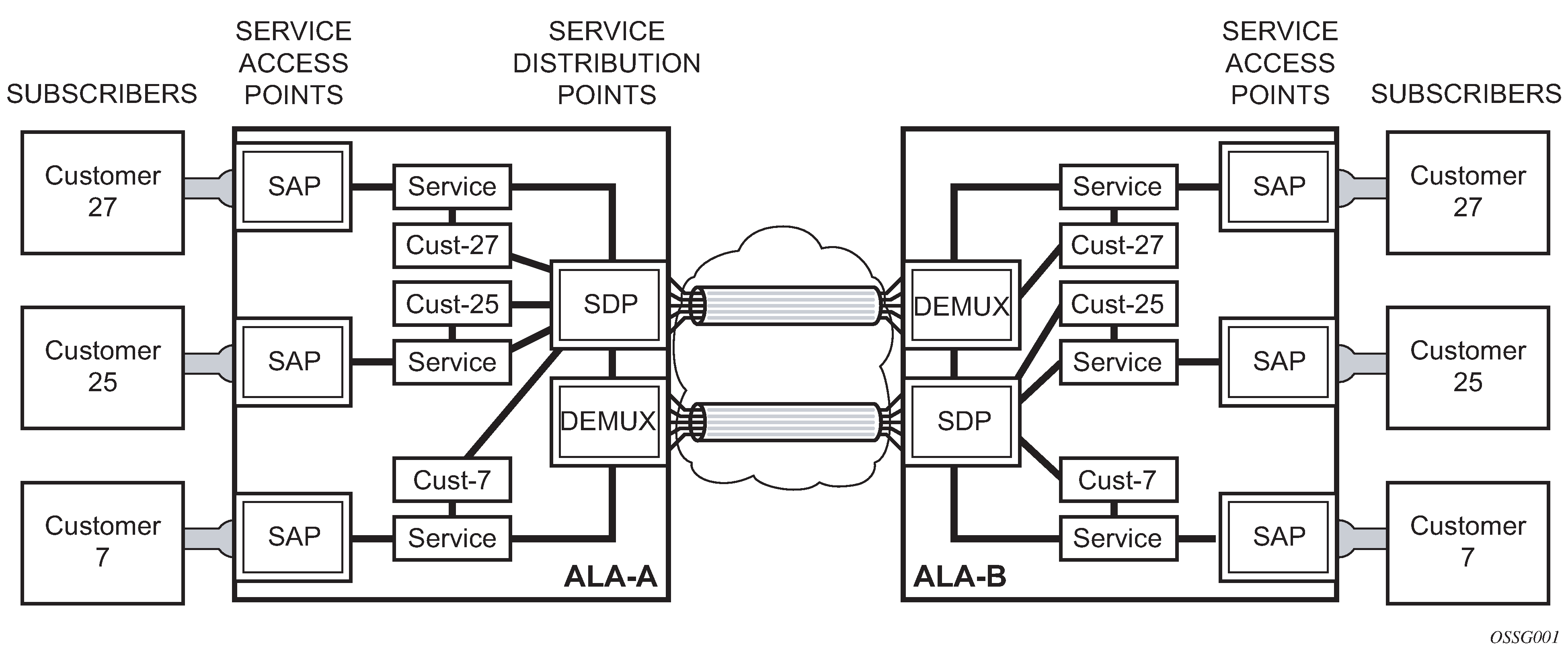
Customers
In this section, the terms customers and subscribers are used synonymously. The most basic required entity is the customer ID value which is assigned when the customer account is created. To provision a service, a customer ID must be associated with the service at the time of service creation.
SAPs
Each subscriber service type is configured with at least one service access point (SAP). A SAP identifies the customer interface point for a service on a router (for example 7750 SR/7950 XRS service access point (SAP)). The SAP configuration requires that slot, XMA or MDA, and port/channel information be specified. The slot, XMA or MDA, and port/channel parameters must be configured before provisioning a service (See the XMAs, Cards, MDAs, and Ports sections of the SR OS Interface Configuration Guide).
A SAP is a local entity to the router and is uniquely identified by:
the physical Ethernet port or SONET/SDH port or TDM channel
the encapsulation type
the encapsulation identifier (ID)
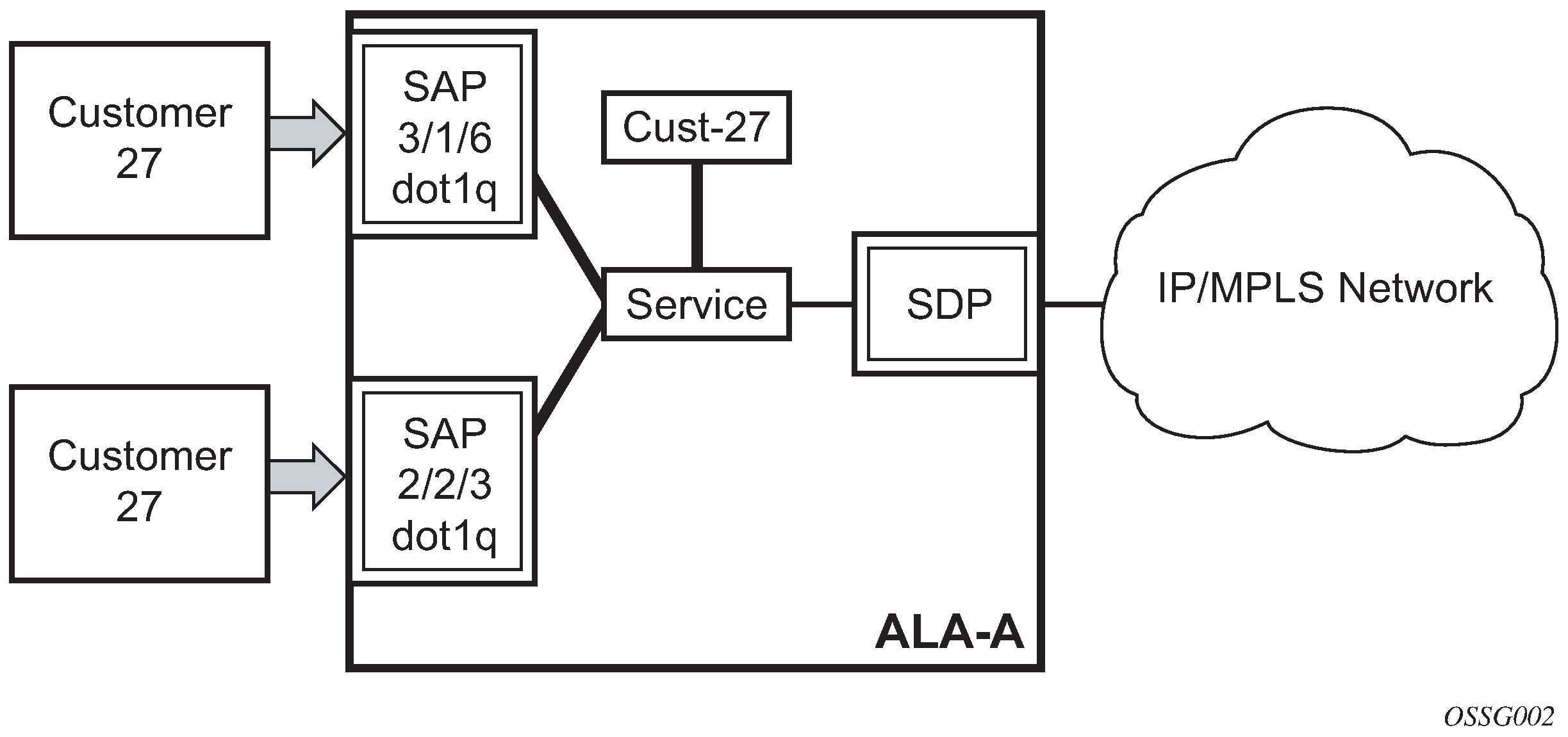
Depending on the encapsulation, a physical port or channel can have more than one SAP associated with it. SAPs can only be created on ports or channels designated as ‟access” in the physical port configuration. SAPs cannot be created on ports designated as core-facing ‟network” ports as these ports have a different set of features enabled in software.
A SAP can also be associated with a pseudowire port instead of an access port. Such SAPs are called pseudowire SAPs. This is only applicable to IES, VPRN, and Epipe services. Pseudowire ports represent pseudowires in enhanced subscriber management (ESM). For a description of pseudowire ports, see the 7450 ESS, 7750 SR, and VSR Triple Play Service Delivery Architecture Guide.
SAP encapsulation types and identifiers
The encapsulation type is an access property of a service Ethernet port or SONET/SDH or TDM channel. The appropriate encapsulation type for the port or channel depends on the requirements to support multiple services on a single port or channel on the associated SAP and the capabilities of the downstream equipment connected to the port or channel. For example, a port can be tagged with IEEE 802.1Q (referred to as dot1q) encapsulation in which each individual tag can be identified with a service. A SAP is created on a specific port or channel by identifying the service with a specific encapsulation ID.
Ethernet encapsulations
The following lists encapsulation service options on Ethernet ports:
null
Null supports a single service on the port. For example, where a single customer with a single service customer edge (CE) device is attached to the port. The encapsulation ID is always 0 (zero).
dot1q
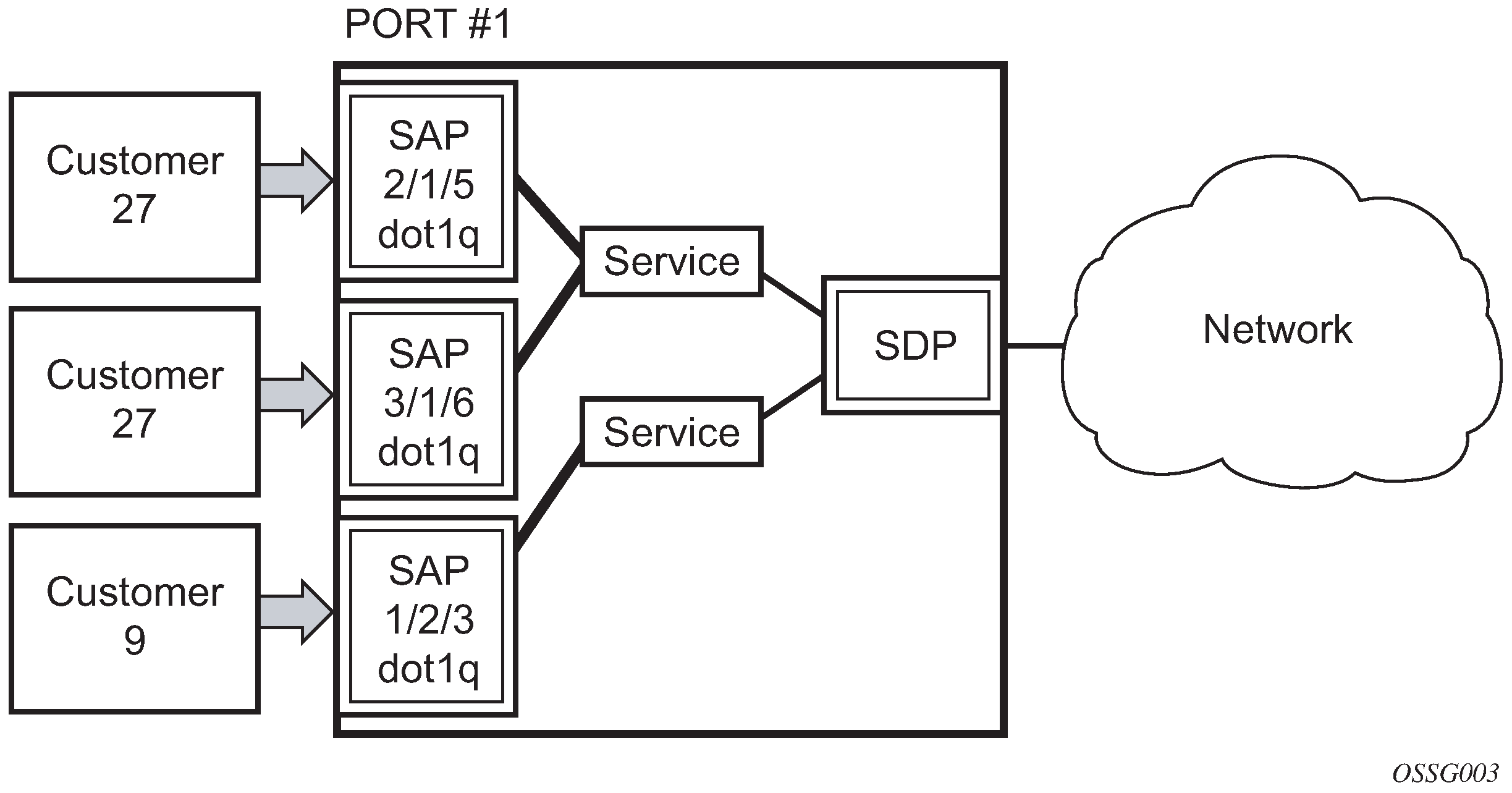
Dot1q supports multiple services for one customer or services for multiple customers (7750 SR/7950 XRS service access point (SAP) and 7750 SR/7950 XRS and 7450 ESS multiple SAPs on a single port/channel). For example, the port is connected to a multi-tenant unit (MTU) device with multiple downstream customers. The encapsulation ID used to distinguish an individual service is the VLAN ID in the IEEE 802.1Q header.
QinQ
The QinQ encapsulation type adds a IEEE 802.1Q tag to the 802.1Q tagged packets entering the network to expand the VLAN space by tagging tagged packets, producing a double tagged frame.
There are several 7750 SR encapsulation service options on SONET/SDH channels:
Internet Protocol Control Protocol (IPCP)
IPCP supports a single IP service on a SONET/SDH port or a single service per channel (if the interface is channelized). This is typically used for router interconnection using point-to-point protocol (PPP).
Bridging Control Protocol (BCP-null)
BCP-null supports a single service on the SONET/SDH port or a single service per channel (if the interface is channelized). This is used for bridging a single service between two devices using PPP over SONET/SDH. The encapsulation ID is always 0 (zero).
Bridging Control Protocol (BCP-dot1q)
BCP-dot1q supports multiple services on the SONET/SDH port/channel. This encapsulation type is used for bridging multiple services between two devices using PPP over SONET/SDH. The encapsulation ID used to distinguish services is the VLAN ID in the IEEE 802.1Q header in the BCP-encapsulated frame.
There are several 7450 ESS encapsulation service options on SONET/SDH channels:
Internet Protocol Control Protocol (IPCP)
IPCP supports a single IP service on a SONET/SDH port. This is typically used for router interconnection using point-to-point protocol (PPP).
Bridging Control Protocol (BCP-null)
BCP-null supports a single service on the SONET/SDH port. This is used for bridging a single service between two devices using PPP over SONET/SDH. The encapsulation ID is always 0 (zero).
Bridging Control Protocol (BCP-dot1q)
BCP-dot1q supports multiple services on the SONET/SDH port. This encapsulation type is used for bridging multiple services between two devices using PPP over SONET/SDH. The encapsulation ID used to distinguish services is the VLAN ID in the IEEE 802.1Q header in the BCP-encapsulated frame.
Default SAP on a dot1q port
On dot1q-encapsulated ports where a default SAP is configured, all packets with q-tags not matching any explicitly defined SAPs are assigned to this SAP. SAPs with default QinQ encapsulation are supported in VPLS, Epipe, IES and VPRN services. Both DHCP snooping and IGMP snooping are supported for QinQ SAPs. In this context, the character ‟*” indicates ‟default” which means ‟allow through”. A 0 value allows the qtag to be missing.
One of the applications where this feature can be applicable is an access connection of a customer who uses the whole port to access Layer 2 services. The internal VLAN tags are transparent to the service provider. This can be provided by a null encapsulated port. A dedicated VLAN (not used by the user) can be used to provide CPE management.
In this type of environment, logically two SAPs exist, a management SAP and a service SAP. The management SAP can be created by specifying a VLAN tag which is reserved to manage the CPE. The service SAP covers all other VLANs and behaves as a SAP on a null-encapsulated port.
There a few constraints related for the use of default SAP on a Dot1q-encapsulated port:
This type of SAP is supported only on VPLS and Epipe services and cannot be created in IES and VPRN services as it cannot preserve VLAN tag markings.
For VPLS SAPs with STP enabled, STP listens to untagged and null-tagged BPDUs only. All other tagged BPDUs are forwarded like other customer packets. This is the same behavior as null-encapsulated ports.
IGMP snooping is not supported on a default SAP. This would require remembering VLAN tags per hosts. By not allowing IGMP snooping of this SAP, all IGMP packets are transparently forwarded.
This type of SAP and a SAP defined by explicit null encapsulation (for example, 1/1/1:0) are mutually exclusive. This avoids conflict as to which SAP untagged frames should be associated.
In a Dot1q port SAP with a non-zero or non-default tag, the tag (referred to as service-delimiting tag) is stripped off on ingress and pushed on egress. For example, the tag is popped from frames received on SAP 1/1/1:10 with a tag that contains VID 10. A tag with VID 10 is pushed onto frames that are sent out of SAP 1/1/1:10.
In case of Dot1q port SAPs with a zero or default tag, no tag is stripped off on ingress, and no tag is pushed on egress. For instance, tags are not stripped off from frames entering 1/1/1:* or 1/1/1:0, and tags are not pushed either on frames egressing those SAPs.
QinQ SAPs
A QinQ SAP has the following format:
qinq <port-id | lag-id>:qtag1.qtag2
Where:
qtag1 is the outer qtag value - [*, null, 0 to 4094]
qtag2 is the inner qtag value - [*, null, 0 to 4094]
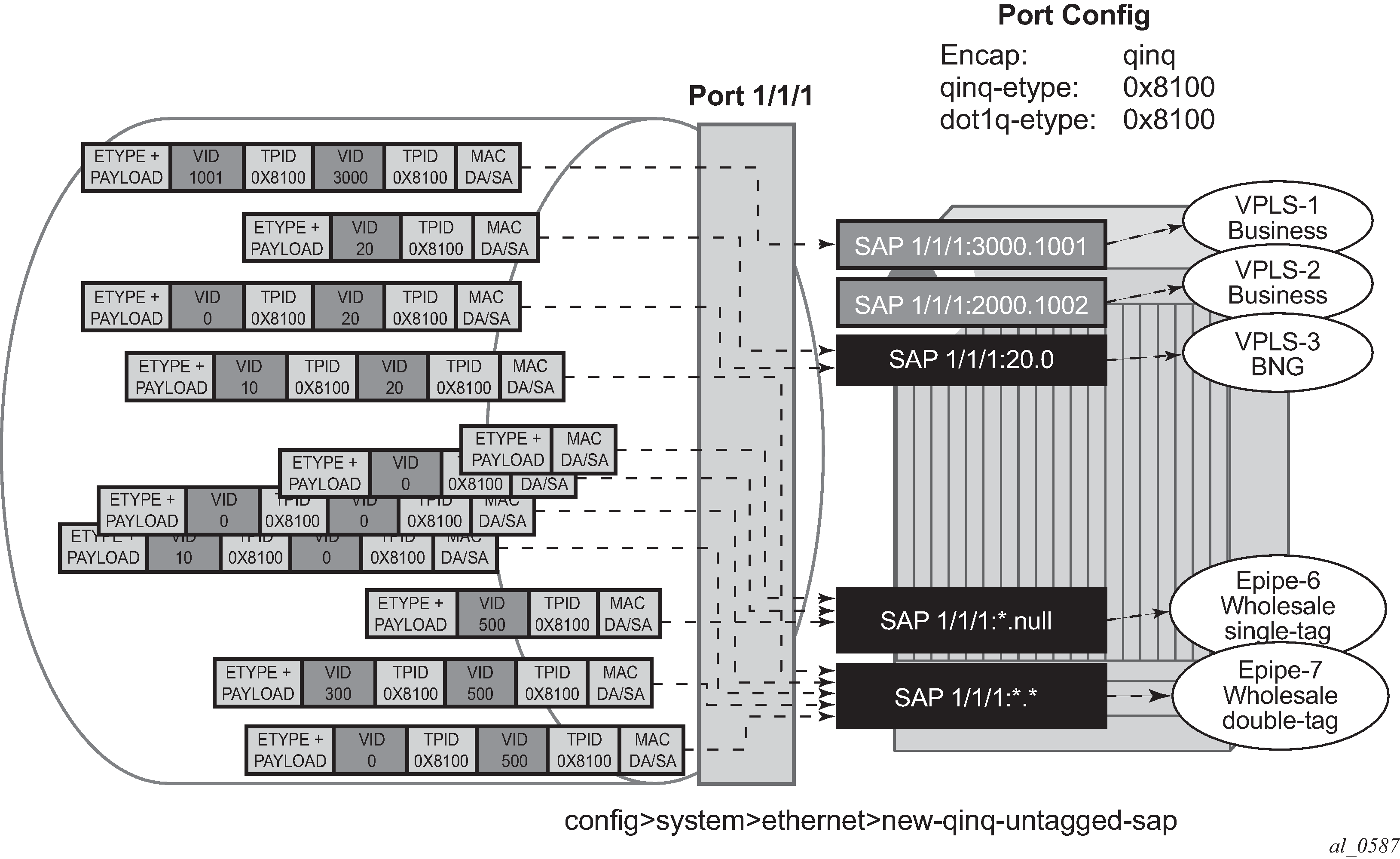
Regular QinQ SAPs have qtag1 and qtag2 values between 1 and 4094. In addition, QinQ Ethernet and LAG ports support the following ‟default” SAPs that can be enabled by the new-qinq-untagged-sap command:
‛*.null’ is defined as a default sap for singly-tagged frames in a QinQ port. This SAP accepts single tags in the range 0 to 4095 as well as untagged traffic. This SAP never pushes any tags on egress.
‛*.*’ is defined as a default sap for doubly-tagged frames in a QinQ port. This SAP accepts untagged, singly tagged, and doubly tagged frames with tags in the range 0..4095. This SAP never pushes any tags on egress.
‛null.null’ is defined as a default SAP for untagged frames only in a QinQ port. This SAP accepts only untagged frames and never pushes any tags on egress. This SAP has higher priority than ‛*.null’ and, or ‛*.*’ when configured on the same QinQ port, therefore it captures untagged frames even if ‛*.null’ or ‛*.*’ are configured.
‛0.*’ can also be used as a default SAP and captures untagged frames, doubly-tagged frames with qtag1 0 (and any value on qtag2) and singly-tagged frames with qtag 0. SAP ‛0.*’ and ‛null.null’ cannot be configured on the same QinQ port.
In addition to the above-mentioned SAPs, qtag2 can also be '0' or '*' when qtag1 is an explicit value in the 1 to 4094 range, for instance: 1/1/1:10.0 or 1/1/1:10.*. Assuming qtag1 is the same value, qtag1.* and qtag1.0 are supported in the same QinQ port. The system never pushes any qtag2 on egress for 1/1/110.0 and 1/1/1:10.*, only qtag1 is pushed. The x.0 accepts only 0 as second tag or not tag (and nothing else), while x.* accepts anything as second tag or no tag.
A SAP lookup is performed when a new frame arrives to a QinQ port. This 'lookup' is based on the <outer-tag, inner-tag> values of the frame.
SAP lookup precedence order for incoming frames shows the SAP lookup precedence order for incoming frames with <qtag1.qtag2> qtag values.
| Incoming frame
qtag1.qtag2 |
System/port settings [new-qinq-untagged-sap=YES] | ||||||
|---|---|---|---|---|---|---|---|
| SAP lookup precedence order | |||||||
| :X.Y | :X.0 | :X.* | :0.* | :null.null | :*.null | :*.* | |
x.y |
1st |
2nd |
3rd |
||||
x.0 |
1st |
2nd |
3rd |
||||
0.y |
1st |
2nd |
|||||
0.0 |
1st |
2nd |
|||||
x |
1st |
2nd |
3rd |
4th |
|||
0 |
1st |
2nd |
3rd |
||||
<untagged> |
1st |
2nd |
3rd |
4th |
|||
The following considerations apply to the information described in SAP lookup precedence order for incoming frames:
All SAP types (:X.Y, :X.0, :X.*, :0.* or :null.null, :*.null and :*.*) are supported in the same QinQ port (with the exception of :0.* and :null.null being incompatible) and, in the table, they are ordered from the most specific (left side) to the least specific with the following VID matching ranges:
X or Y means <1 to 4094>
* means <0 to 4095> or untagged
null means 'no tag'
0 means VID 0 or untagged
On egress, the system pushes a tag with a VID value for X and Y, whereas no tag is pushed on egress for values 0, * or null. For example:
On SAP 1/1/1:10.20, the system pushes tags with VIDs 10 and 20 (outer and inner respectively) on egress.
On SAP 1/1/1:10.0 or 1/1/1:10.* the system pushes only one tag with VID 10 on egress.
On SAPs 1/1/1:0.*, 1/1/1:null.null, 1/1/1:*.null or 1/1/1:*.* the system never pushes any tags on egress.
The user can decide the SAP types that are configured in a specific port. Not all SAP types must be configured in a port.
SAP lookup precedence order for incoming frames shows the lookup behavior for ingress frames and priority across SAPs in case more than one can match a specific ingress frame. The SAP lookup result for a specific frame does not depend on the operational status of the SAP. For instance:
In a port with SAPs 1/1/1:0.* and 1/1/1:*.* defined, the SAP lookup for a specific frame with VIDs (0, 300) yields SAP 1/1/1:0.* regardless of its operational status.
The frame only matches SAP 1/1/1:*.* when the 0.* SAP is removed from the configuration.
The following applies to VLAN tag handling:
The system does not strip-off any tags for frames entering the default SAPs (:0.*, :null.null, :*.null or :*.*).
No extra tags are added when the system transmits frames on the default SAPs (:0.*, :null.null, :*.null or :*.*).
The following examples illustrate the SAP classification QinQ ports. The examples assume that the new-qinq-untagged-sap command is enabled.
As shown in Example 1 SAP classification QinQ ports, assuming that the new-qinq-untagged-sap command is enabled, the following SAPs are defined on the same port:
1/1/1:3000.1001 - business customer - vpls-1
1/1/1:2000.1002 - business customer - vpls-2
1/1/1:20.0 - BNG traffic - vpls-3
1/1/1:20.* - business customer - epipe-4
1/1/1:0.* - business customer - epipe-5
1/1/1:*.null - wholesaling single tag - epipe-6
1/1/1:*.* - wholesaling double tag - epipe-7
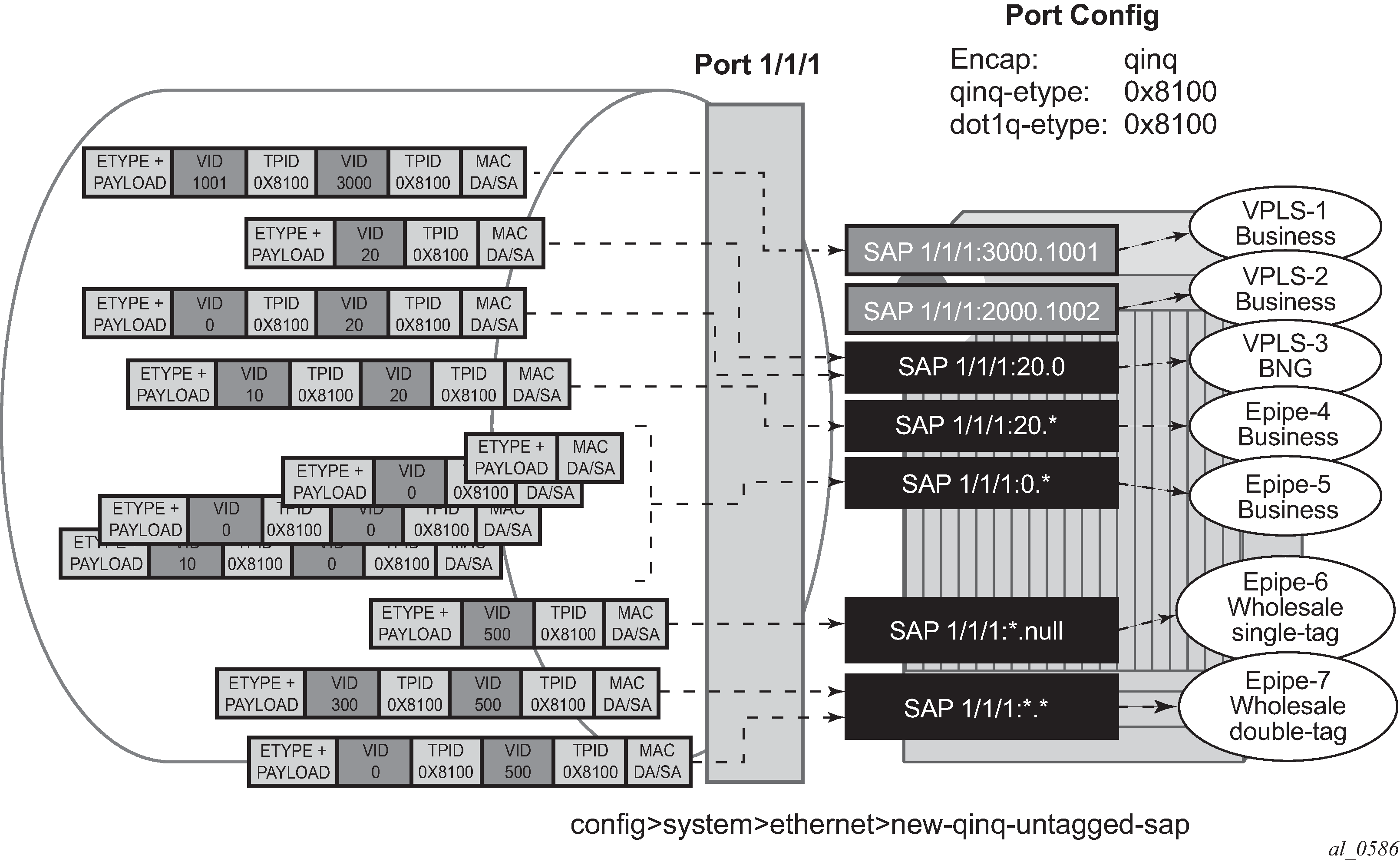
Based on the SAPs configuration described above, the incoming traffic is classified in the following way - notation (outer-VID, inner-VID):
(3000, 1001) goes to vpls-1
(20) goes to BNG (vpls-3)
(20, 0) goes to BNG (vpls-3)
(20, 10) goes to epipe-4
untagged, (0), (0, 0), and (0, 10) go to epipe-5
(500) goes to wholesaling single tag (epipe-6)
(500, 300) and (500, 0) go to wholesaling double tag (epipe-7)
Example 2 SAP classification QinQ ports highlights how untagged, VID=0 tagged frames and 20.X frames are classified in the absence of the 0.* and 20.* SAPs.
As described in Example 2 SAP classification QinQ ports, assuming the new-qinq-untagged-sap command is enabled, the following SAPs are defined on the same port:
1/1/1:3000.1001 - business customer - vpls-1
1/1/1:2000.1002 - business customer - vpls-2
1/1/1:20.0 - BNG traffic - vpls-3
1/1/1:*.null - wholesaling single tag - epipe-6
1/1/1:*.* - wholesaling double tag - epipe-7
Incoming traffic - notation (outer-VID, inner-VID)
(3000, 1001) goes to vpls-1
(20) goes to BNG (vpls-3)
(20, 0) goes to BNG (vpls-3)
(20, 10) goes to wholesaling double tag (epipe-7)
untagged and (0) go to wholesaling single tag (epipe-6)
(500) goes to wholesaling single tag (epipe-6)
(500, 300) and (500, 0) go to wholesaling double tag (epipe-7)
(0,0), and (0,10) goes to wholesaling double tag (epipe-7)
The following constraints must be considered when configuring default QinQ SAPs (:0.*, :null.null, :*.null, :*.*):
Only supported in Ethernet ports or LAG.
Only supported on Epipe, PBB-Epipe, VPLS and I-VPLS services. They are not supported on VPRN, IES, R-VPLS or B-VPLS services.
Capture SAPs with encapsulation :*.* cannot coexist with a default :*.* SAP on the same port.
Inverse-capture SAPs (*.x) are mutually-exclusive with :*.null SAPs.
*.null SAPs are not supported for Open Flow matching and forwarding.
The following applies to Eth-CFM:
Primary VLAN is not supported.
Eth-CFM extractions occur within the service after the packet lookup has determined which service the inbound packet belongs to.
All four SAPs (null.null, *.null, *.* and 0.*) are treated equally by ETH-CFM. Only untagged CFM PDUs are extracted by a local MEP or MIP. Additional tags in the header may match the service context but are not extracted by ETH-CFM for processing.
ETH-CFM PDU transmission encapsulation is based on the SAP configuration. This means that the ETH-CFM PDUs are transmitted out all four of these SAPs untagged. Care must be taken to ensure that there is no downstream service that may intercept the ETH-CFM PDUs that are not intended for that service. See SAP lookup precedence order for incoming frames for a description of the SAP lookup precedence order for incoming frames and to understand the potential consequences.
Default QinQ SAPs do not support the following features:
PW-SAPs
Eth-tunnel or eth-ring SAPs
VLAN-translation copy-outer
E-Tree root-leaf-tag SAPs
Subscriber-management features
BPDU-translation
Eth-tunnels
IGMP-snooping
MLD-snooping
Services and SAP encapsulations
The services and SAP encapsulations are listed in Service and SAP encapsulations.
| Port type | Encapsulation |
|---|---|
Ethernet |
Null |
Ethernet |
Dot1q |
Ethernet |
QinQ |
SONET/SDH |
IPCP |
SONET/SDH |
BCP-null |
SONET/SDH |
BCP-dot1q |
SONET/SDH |
Cisco HDLC |
SAP configuration considerations
When configuring a SAP, consider the following:
A SAP is a local entity and only locally unique to a specific device. The same SAP ID value can be used on another Nokia router.
There are no default SAPs. All SAPs in subscriber services must be created.
The default administrative state for a SAP at creation time is administratively enabled.
When a SAP is deleted, all configuration parameters for the SAP are also deleted. For Internet Enhanced Service (IES), the IP interface must be shut down before the SAP on that interface may be removed.
A SAP is owned by and associated with the service in which it is created in each router.
A port or channel with a dot1q or BCP-dot1q encapsulation type means the traffic for the SAP is identified based on a specific IEEE 802.1Q VLAN ID value. The VLAN ID is stripped off at SAP ingress and the appropriate VLAN ID placed on at SAP egress. As a result, VLAN IDs only have local significance, so the VLAN IDs for the SAPs for a service need not be the same at each SAP.
If a port or channel is administratively shutdown, all SAPs on that port or channel are operationally out of service.
A SAP cannot be deleted until it has been administratively disabled (shutdown).
Each SAP can have one each of the following policies assigned:
Ingress filter policy
Egress filter policy
Ingress QoS policy
Egress QoS policy
Accounting policy
Ingress scheduler policy
Egress scheduler policy
G.8032 protected Ethernet rings
Ethernet ring protection switching offers ITU-T G.8032 specification compliance to achieve resiliency for Ethernet Layer 2 networks. G.8032 (Ethernet-ring) is built on Ethernet OAM and often referred to as Ring Automatic Protection Switching (R-APS).
For further information about Ethernet rings, see G.8032 Ethernet ring protection switching.
SAP bandwidth CAC
This feature provides a bandwidth Connection Admission Control (CAC) function per port or LAG based on an administrator bandwidth configured on a SAP and on the associated port or LAG. A booking factor is provided to allow overbooking or underbooking of the sum of the SAP bandwidth compared to the port or LAG bandwidth.
The administrator bandwidth is a statically configured abstract value that could represent either the ingress or egress bandwidth, or both.
The goal of the CAC function is to ensure that the sum of the administrator SAP bandwidth on a port or LAG does not exceed the administrator bandwidth configured on that port or LAG.
This feature is supported on all service Ethernet SAPs, excluding PW SAPs, Ethernet tunnels and subscriber group interface SAPs. It is not supported in a VPLS or Epipe SAP template. It is applicable to both access and hybrid ports or LAGs; in the case of a hybrid port or LAG, the SAP CAC bandwidth only applies to the access operation.
By default, a SAP, port, or LAG has no administrator bandwidth configured, in which case it is excluded from the CAC function. Configuring an administrator bandwidth on a SAP enforces the CAC function.
An administrator bandwidth can only be configured on a SAP that is connected to a port or LAG on which an administrator bandwidth is already configured. When a LAG is configured, the administrator bandwidth and booking factor on its constituent ports are ignored.
The system tracks the requested and available bandwidth per port or LAG, where the available bandwidth is equal to the administrator bandwidth on the port or LAG, with the booking factor applied, minus the sum of administrator bandwidth configured on its SAPs. An attempt to increase a SAP's administrator bandwidth fails if there is insufficient available bandwidth on its port or LAG.
Use the following CLI commands to configure the administrator bandwidth and booking factor for the port or LAG.
configure
    lag <lag-id>
        access
            bandwidth <bw-value>
            booking-factor <percentage>
    port <port-id>
        ethernet
            access
                bandwidth <bw-value>
                booking-factor <percentage>
    service
        [ cpipe | epipe | ipipe | vpls] <service-id>
            sap <sap-id>
                bandwidth <bw-value>
        [ies | vprn] <service-id>
            interface <ip-int-name>
                sap <sap-id>
                    bandwidth <bw-value>
Dynamic changes in administrator bandwidth and booking factor are possible without having to disable the SAP, port, or LAG.
A SAP is allocated bandwidth on a port or LAG regardless of whether the SAP and port or LAG are administratively or operationally up or down. The administrator bandwidth must be removed from the SAP configuration to free up its bandwidth on the port or LAG. Actions such as clearing the card or MDA, power cycling the card, or removing and reinserting a card or MDA do not change the CAC state of the SAP and port or LAG.
CAC enforcement
The CAC is enforced when an administrator bandwidth is configured on a SAP, which may be when the administrator bandwidth is initially configured or when an existing administrator bandwidth value is modified.
The CAC enforcement is achieved by comparing the newly requested SAP administrator bandwidth (the incremental administrator bandwidth being configured above any currently assigned administrator bandwidth) with the available administrator bandwidth on its port or LAG.
The operation is as follows:
If a SAP's admin bandwidth is increased and the incremental requested admin bandwidth is:
larger than the port or LAG available bandwidth then the command to increase the SAP admin bandwidth fails.
-
smaller or equal to the available port or LAG bandwidth then the incremental bandwidth is subtracted from the available port or LAG bandwidth.
If a SAP's admin bandwidth is reduced then the available port or LAG bandwidth is increased accordingly.
If the port or LAG admin bandwidth is increased, the available port or LAG bandwidth is increased accordingly.
If the port or LAG admin bandwidth is decreased, the available port or LAG bandwidth is decreased accordingly. However, if the resulting available bandwidth would be less than the sum of the currently allocated SAP admin bandwidth on that port or LAG, then the command to decrease the admin bandwidth fails.
If the port or LAG booking factor is decreased, the available port or LAG bandwidth is decreased accordingly. However, if the resulting available bandwidth would be less than the sum of the currently allocated SAP admin bandwidth on that port or LAG, then the command to decrease the booking factor fails.
If the SAP admin bandwidth is removed, it is excluded from the SAP bandwidth CAC function. Its admin bandwidth is added to the related port or LAG available bandwidth.
The port or LAG admin bandwidth can only be removed if all of its SAPs are excluded from the CAC function.
In the following example, a port is configured with an administrator bandwidth of 500 Mb/s, and a SAP on that port is configured with a bandwidth of 10 Mb/s. The show output displays these configured values together with the available and booked administrator bandwidth for the port. An increase of the SAP administrator bandwidth to 600 Mb/s is attempted; the operation fails because of insufficient available administrator bandwidth on the port.
The booking factor for the port is increased to 200% and the increase of the SAP administrator bandwidth to 600 Mb/s is successful as the available administrator bandwidth for the port becomes 1 Gb/s. The booked administrator bandwidth for the port is 600 Mb/s and so the available administrator bandwidth for the port becomes 400 Mb/s.
*A:PE# configure port 1/1/1 ethernet access bandwidth 500000
*A:PE# configure service vpls 1 sap 1/1/1:1 bandwidth 10000
*A:PE# show service id 1 sap 1/1/1:1 detail | match Bandwidth
Bandwidth          : 10000
*A:PE# show port 1/1/1 detail | match expression "Bandwidth | BW"
Access Bandwidth   : 500000                  Booking Factor : 100
Access Available BW: 490000
Access Booked BW   : 10000
*A:PE# configure service vpls 1 sap 1/1/1:1 bandwidth 600000
MINOR: SVCMGR #2664 Insufficient bandwidth available
*A:PE# show service id 1 sap 1/1/1:1 detail | match Bandwidth
Bandwidth          : 10000
*A:PE# *A:PE# configure port 1/1/1 ethernet access booking-factor 200
*A:PE# configure service vpls 1 sap 1/1/1:1 bandwidth 600000
*A:PE# show service id 1 sap 1/1/1:1 detail | match Bandwidth
Bandwidth          : 600000
*A:PE# show port 1/1/1 detail | match expression "Bandwidth | BW"
Access Bandwidth   : 500000                  Booking Factor : 200
Access Available BW: 400000
Access Booked BW   : 600000
*A:PE#
Connection profile VLAN SAPs
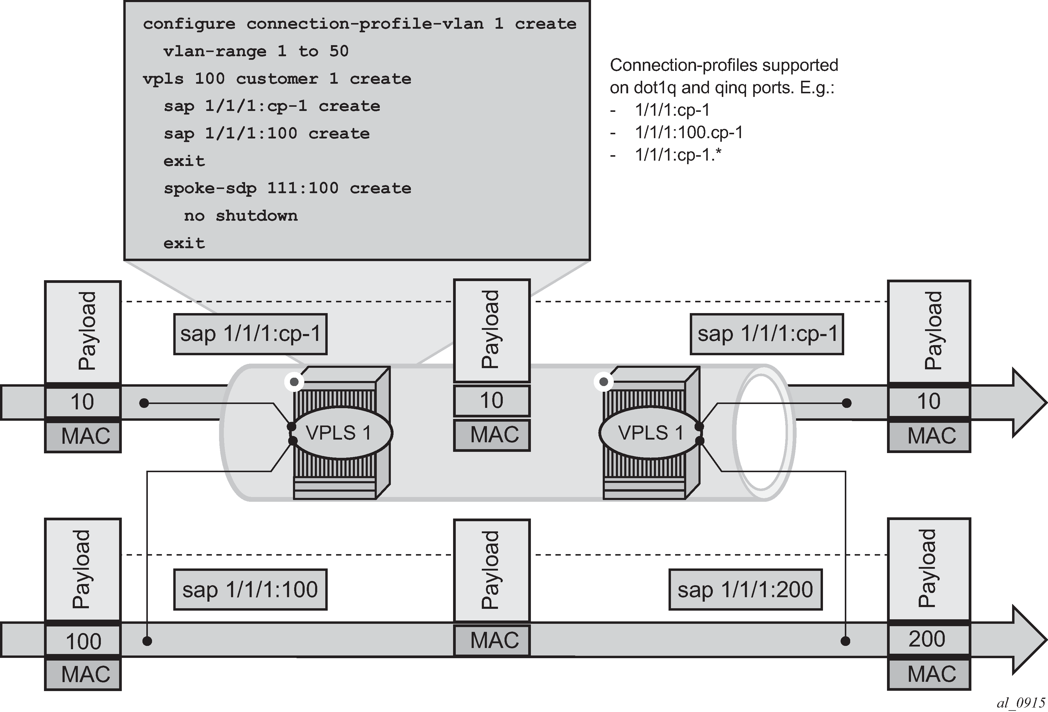
The connection-profile-vlan SAPs (CP SAPs) allow the association of a range of customer VIDs to a specific SAP. CP SAPs can be used to build Layer 2 services that are fully compatible with MEF 10.3 Bundling Service Attributes and RFC 7432 EVPN VLAN Bundle Service interfaces.
The config>connection-profile-vlan>vlan-range command defines the range of customer VIDs to be matched when the connection-profile-vlan is associated with a dot1q or QinQ SAP.
The following example shows the command usage in dot1q and QinQ SAPs:
A:PE# configure connection-profile-vlan 1 create
        vlan-range 5 to 100
        vlan-range 150 to 300
        vlan-range 350
    exit
The following is an example configuration output:
A:PE>config>service>vpls# info
----------------------------------------------
<snip>
sap 1/1/1:cp-1 create
    no shutdown
exit
sap 1/1/2:100.cp-1 create
    no shutdown
exit
sap 1/1/3:cp-1.* create
    no shutdown
exit
<snip>
For VLAN manipulation, the CP SAP behavior is equivalent to the default SAP’s (when the ingress VID falls into the range configured in the CP), where the range of VIDs included is not service-delimiting and therefore, the VIDs are not pushed/popped. The main differences between the CP SAPs and the default SAPs are:
A default SAP consumes less resources; a default SAP consumes one SAP instance, whereas a CP SAP consumes SAP instances equal to the number of VLANs in the range. To check the number of SAP instances used by the system, run the following CLI commands:
See the 7450 ESS, 7750 SR, 7950 XRS, and VSR Basic System Configuration Guide for a complete description of the tools dump resource-usage command.
*A:Dut# tools dump resource-usage system
===============================================================================
Resource Usage Information for System
===============================================================================
                                                  Total   Allocated        Free
-------------------------------------------------------------------------------
<snip>
                                SAP Entries  |   262143           8      262135
===============================================================================

*A:Dut# tools dump resource-usage card 1 fp 1
===============================================================================
Resource Usage Information for Card Slot #1 FP #1
===============================================================================
                                                  Total   Allocated        Free
-------------------------------------------------------------------------------
<snip>
                              SAP Instances  |    63999         254       63745
<snip>
===============================================================================
Unlike the default SAP, a CP SAP cannot coexist with a vlan SAP that is in the same range. For example, 1/1/1:* and 1/1/1:100 can coexist; in contrast, 2/1/1:cp-1 (cp-1 = vlan 1 to 200) and 2/1/1:100 cannot coexist.
VLAN tag handling shows customer VID processing by SAPs with service-delimiting VIDs, and by CP SAPs. In this example, SAP 1/1/1:cp-1 does not strip off or push VID 10, whereas SAP 1/1/1:100 and SAP 1/1/1:200 do strip off and push the corresponding VID.
A connection-profile-vlan allows the configuration of VLAN ranges with the following characteristics:
A vlan-range can be defined as a single VID (for example, vlan-range 101), or two VIDs delimiting the beginning and the end of the range (for example, vlan-range 105 to 107).
Discontinuous ranges are allowed.
Overlapping ranges are not allowed within the same connection-profile-vlan configuration. Overlapping VLAN ranges can exist across different connection profiles if they are not applied to the same port (in the case of dot1q ports), or the same port and service-delimiting tag (in the case of QinQ ports). For example:
1/1/1:x.cp-1 and 1/1/1:y.cp-2 can coexist on the same port, where cp-1 includes VIDs [10-20] and cp-2 includes VIDs [15-25]
if x=y, then the overlapping is not possible in the above case
A connection-profile-vlan must have at least one range (with a single or multiple VIDs) before it can be associated with a SAP.
A connection-profile-vlan cannot contain an explicitly defined SAP within any of the ranges when the explicit SAP is configured on the same port.
The configured VLAN ranges cannot contain VIDs 0 or 4095.
The connection-profile-vlan SAPs are supported in Layer 2 services only. No IES or VPRN services can contain CP SAPs.
CP SAPs are supported on access or hybrid ports but are not on network interfaces.
CP SAPs are supported in (non-PBB) Epipe and VPLS services.
CP SAPs support SAP based QoS policies. VID type MAC criteria can be used on CP SAPs to apply specific QoS on a VLAN within the connection-profile-vlan.
The legacy OAM commands (mac-ping, mac-trace, mac-purge, and mac-populate) are not supported for CP SAPs.
Using connection-profile-vlan in dot1q ports
SAP lookup matching order for dot1q ports describes the SAP lookup matching order that is applied when connection-profile-vlan is used in dot1q ports.
| Incoming frame qtag VID value | SAP lookup precedence order (:0 and :* are mutually-exclusive on the same port) |
|||
|---|---|---|---|---|
| :X | :CP | :0 | :* | |
x (belongs to the CP range) |
1st |
1st |
2nd |
|
0 |
1st |
1st |
||
<untagged> |
1st |
1st |
||
Using connection-profile-vlan in QinQ ports
SAP lookup matching order for QinQ ports describes the SAP lookup matching order that is applied when connection-profile-vlan is used in QinQ ports.
| Incoming frame | System/port settings = new-qinq-untagged-sap | |||||||
|---|---|---|---|---|---|---|---|---|
| qtag1.qtag2 | SAP lookup precedence order (assumption: X and Y are defined in CP ranges) |
|||||||
| :X.Y | :X.0 | :X.CP | :CP.* | :X.* | :0.* | :*.null | :*.* | |
x.y |
1st |
1st |
2nd |
2nd |
3rd |
|||
x.0 |
1st |
2nd |
2nd |
3rd |
||||
0.y |
1st |
2nd |
||||||
0.0 |
1st |
2nd |
||||||
x |
1st |
2nd |
2nd |
3rd |
4th |
|||
0 |
1st |
2nd |
3rd |
|||||
<untagged> |
1st |
2nd |
3rd |
|||||
The following considerations apply when connection profile VLAN (CP VLAN) is used in QinQ ports:
A CP can be defined for inner or outer tags but not both at the same time; for example, ‟:X.CP” and ‟:CP.*” are possible, but not ‟:CP.CP”.
It is important to note that ‟:CP:Y” is not allowed; for example, if a CP is defined at the outer VID, the inner VID can only be a ‟*” or a ‟0”.
‟:0.CP” SAPs are not allowed; if the outer VID is 0, the inner VID cannot be a connection-profile-vlan value.
A CP cannot contain a VID that is associated with an explicitly defined inner or outer tag in a specific port. For example, assuming that X and Y are tags defined in ‟CP”, a specific port can be defined with ":X.CP" or ":Y.CP", but not with ":X.Y" and ":X.CP" or ":CP.*" and "X.*" in the same port.
The following combinations are allowed:
:CP.0 (matches frames with outer tags contained in CP and inner tags 0 or null)
:CP.* (matches frames with outer tags contained in CP and any inner tags)
In the case where a VLAN tag combination matches different SAPs, the highest priority SAP is picked, irrespective of its oper-status, as long as the SAP is still created. Therefore, if the SAP is down, the frames do not go to a different SAP. For example, suppose that ingress frames with VIDs 10.25 are classified as part of sap 10.cp-1. Only when sap 10.cp-1 is removed from the configuration do the frames with VIDs 10.25 go to sap cp-1.*.
# cp-1 includes vlan ids (10-100).
sap 1/1/4:cp-1.* create
exit
sap 1/1/4:10.cp-1 create
exit
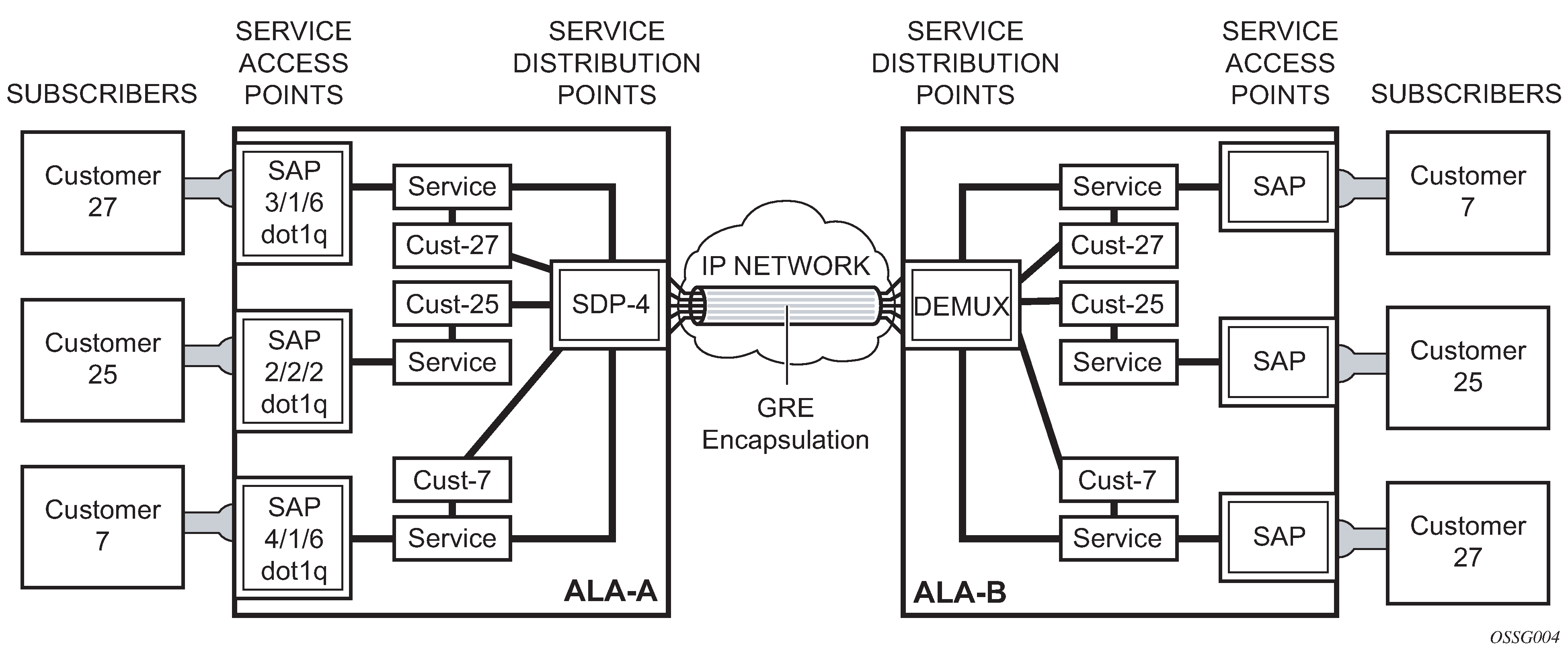
Service distribution points
A Service Distribution Point (SDP) acts as a logical way to direct traffic from one router to another through a unidirectional (one-way) service tunnel. The SDP terminates at the far-end device which directs packets to the correct service egress SAPs on that device. A distributed service consists of a configuration with at least one SAP on a local node, one SAP on a remote node, and an SDP binding the service to the service tunnel.
An SDP has the following characteristics:
An SDP is locally unique to participating routers. The same SDP ID can appear on other Nokia routers.
An SDP uses the system IP address to identify the far-end edge router.
An SDP is not specific to any one service or any type of service. When an SDP is created, services are bound to the SDP. An SDP can also have more than one service type associated with it.
All services mapped to an SDP use the same transport encapsulation type defined for the SDP (either GRE, MPLS, or L2tPv3).
An SDP is a management entity. Even though the SDP configuration and the services carried within are independent, they are related objects. Operations on the SDP affect all the services associated with the SDP. For example, the operational and administrative state of an SDP controls the state of services bound to the SDP.
An SDP from the local device to a far-end router requires a return path SDP from the far-end router back to the local router. Each device must have an SDP defined for every remote router to which it wants to provide service. SDPs must be created first, before a distributed service can be configured.
SDP binding
To configure a distributed service from ALA-A to ALA-B, the SDP ID (1) (shown in GRE service distribution point (SDP) pointing from ALA-A to ALA-B) must be specified in the service creation process to ‟bind” the service to the tunnel (the SDP). Otherwise, service traffic is not directed to a far-end point and the far-end devices cannot participate in the service (there is no service). To configure a distributed service from ALA-B to ALA-A, the SDP ID (5) must be specified.
Spoke and mesh SDPs
When an SDP is bound to a service, it is bound as either a spoke SDP or a mesh SDP. The type of SDP indicates how flooded traffic is transmitted.
A spoke SDP is treated like the equivalent of a traditional bridge ‟port” where flooded traffic received on the spoke SDP is replicated on all other ‟ports” (other spoke and mesh SDPs or SAPs) and not transmitted on the port it was received.
All mesh SDPs bound to a service are logically treated like a single bridge ‟port” for flooded traffic where flooded traffic received on any mesh SDP on the service is replicated to other ‟ports” (spoke SDPs and SAPs) and not transmitted on any mesh SDPs.
SDP using BGP route tunnel
SDP is enhanced to use BGP route tunnel to extend inter-AS support for routes and services. An SDP can be configured based on service transport method (for example, GRE or MPLS tunnel). MPLS SDP support is enhanced to allow a BGP route tunnel to reach the far-end PE.
A single method of tunneling is allowed per SDP (for example, LDP, RSVP-TE LSP or BGP route tunnel).
For the inter-AS far-end PE, next-hop for BGP route tunnel must be one of the local ASBR. The LSP type selected to reach the local ASBR (BGP labeled route next-hop) must be configured under the BGP global context. LDP must be supported to provide transport LSP to reach the BGP route tunnel next-hop.
Only BGP route labels can be used to transition from ASBR to the next-hop ASBR. The global BGP route tunnel transport configuration option must be entered to select an LSP to reach the PE node from ASBR node. On the last BGP segment, both BGP and LDP and LDP routes may be available to reach the far-end PE from the ASBR node. LDP LSP must be preferred because of higher protocol priority. This leads to just one label besides other labels in stack to identify VC or VPN at far-end PE nodes.
SDP keepalives
SDP keepalives actively monitor the SDP operational state using periodic Nokia SDP ping echo request and echo reply messages. Nokia SDP ping is a part of Nokia’s suite of service diagnostics built on an Nokia service-level OA&M protocol. When SDP ping is used in the SDP keepalive application, the SDP echo request and echo reply messages are a mechanism for exchanging far-end SDP status.
Configuring SDP keepalives on a specific SDP is optional. SDP keepalives for a particular SDP have the following configurable parameters:
admin up/admin down state
hello time
message length
max drop count
hold down time
SDP keepalive echo request messages are only sent when the SDP is completely configured and administratively up and SDP keepalives is administratively up. If the SDP is administratively down, keepalives for the SDP are disabled.
SDP keepalive echo request messages are sent out periodically based on the configured Hello Time. An optional message length for the echo request can be configured. If max drop count echo request messages do not receive an echo reply, the SDP is immediately brought operationally down.
If a keepalive response is received that indicates an error condition, the SDP is immediately brought operationally down.
When a response is received that indicates the error has cleared and the hold down time interval has expired, the SDP is eligible to be put into the operationally up state. If no other condition prevents the operational change, the SDP enters the operational state.
SDP administrative groups
This feature introduces the support of SDP administrative groups, referred to as SDP admin groups. SDP admin groups provide a way for services using a pseudowire template to automatically include or exclude specific provisioned SDPs. SDPs sharing a specific characteristic or attribute can be made members of the same admin group.
The user first creates the admin groups that are to be used by SDPs on this node:
config>service>sdp-group>group-name group-name value group-value create
A maximum of 32 admin groups can be created. The no option is only allowed if the group-name is not referenced in a PW template or SDP.
The group value ranges from zero (0) to 31. It is uniquely associated with the group name at creation time. If the user attempts to configure another group name for a group value that is already assigned to an existing group name, the SDP admin group creation is failed. The same happens if the user attempts to configure an SDP admin group with a new name but associates it to a group value already assigned to an existing group name.
Next, the user configures the SDP membership in admin groups:
config>service>sdp>sdp-group group-name
The user can enter a maximum of one (1) admin group name at once. The user can execute the command multiple times to add membership to more than one admin group. The admin group name must have been configured or the command is failed. Admin groups are supported on an SDP of type GRE and of type MPLS (BGP/RSVP/LDP). They are also supported on an SDP with the mixed-lsp-mode option enabled.
The user then selects which admin groups to include or exclude in a pseudowire template:
config>service>pw-template>sdp-include group-name
config>service>pw-template>sdp-exclude group-name
The admin group name must have been configured or the command is failed. The user can execute the command multiple times to include or exclude more than one admin group. The sdp-include and sdp-exclude commands can only be used with the use-provisioned-sdp or prefer-provisioned-sdp options. If the same group name is included and excluded within the same PW template, only the exclude option is enforced.
Any changes made to the admin group sdp-include and sdp-exclude constraints are only reflected in existing spoke SDPs after the following command has been executed:
tools>perform>service>eval-pw-template>allow-service-impact
When the service is bound to the PW template, the SDP selection rules enforce the admin group constraints specified in the sdp-include and sdp-exclude commands.
config>service>vpls>bgp>pw-template-binding policy-id
config>service>epipe>spoke-sdp-fec>pw-template-bind policy-id
SDP admin groups can be enabled on all router services that make use of the pseudowire template (BGP-AD VPLS service, BGP-VPLS service, BGP-VPWS and FEC129 VLL service). In the latter case, SR OS provides support at the T-PE nodes only.
SDP selection rules
In the current SDP selection process, all provisioned SDPs with the correct far-end IP address, the correct tunnel-far-end IP address, and the correct service label signaling are considered. The SDP with the lowest admin metric is selected. If more than one SDP with the same lowest metric are found, then the SDP with the highest sdp-id is selected. The type of SDP, GRE or MPLS (BGP/RSVP/LDP) is not a criterion in this selection.
The selection rule with SDP admin groups is modified such that the following admin-group constraints are applied up front to prune SDPs that do not comply:
If one or more sdp-include statement is part of the PW template, then an SDP that is a member of one or more of the included groups is considered. With the sdp-include statement, there is no preference for an SDP that belongs to all included groups versus one that belongs to one or fewer of the included groups. All SDPs satisfying the admin-group constraint are considered and the selection above based on the lowest metric and highest sdp-id is applied.
If one or more sdp-exclude statement is part of the PW template, then an SDP that is a member of any of the excluded groups is not considered.
Class-based forwarding
Application of class-based forwarding over RSVP LSPs
Class-based forwarding over RSVP LSPs allows a service packet to be forwarded over a specific RSVP LSP, part of an SDP, based on its ingress determined forwarding class. The LSP selected depends on the operational status and load-balancing algorithms used for ECMP and LAG spraying.
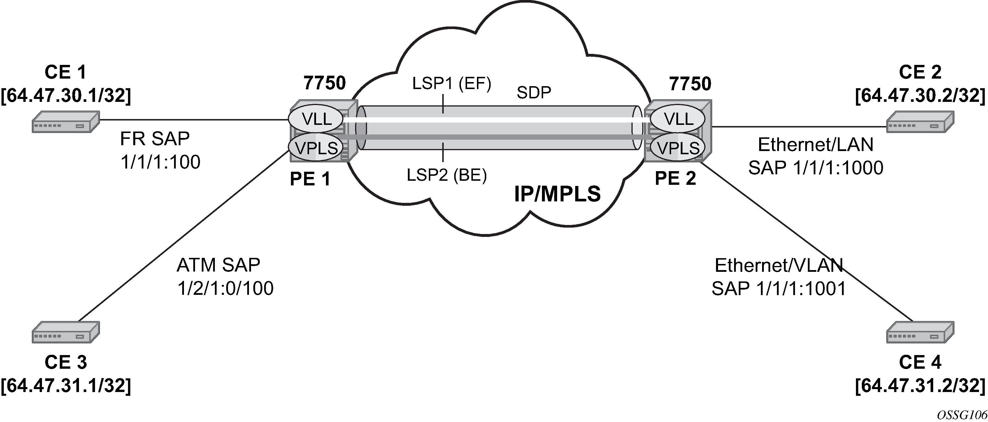
Class-based forwarding over SDP LSPs illustrates the use of class-based forwarding to direct packets of a service to specific RSVP or static LSPs that are part of the same SDP based on the packets' forwarding class. The forwarding class of the packet is the one assigned to the packet as a result of applying the ingress QoS policy to the service SAP. The VLL service packets are all classified into the ef forwarding class and those that are destined for PE2 are forwarded over LSP1. Multicast and broadcast are classified into the be class and are forwarded over LSP2.
This feature allows service providers to dedicate specific LSPs with a determined level of traffic engineering and protection to select service packets. For example, packets of a VoIP service are assigned the ef class to expedite their forwarding but are also sent over carefully traffic-engineered and FRR-protected LSP paths across the service provider network.
Operation of class-based forwarding over RSVP LSPs
The Nokia router’s class-based forwarding feature applies to a set of LSPs that are part of the same SDP. Each LSP must be configured as part of an SDP specifying the forwarding classes it supports. A forwarding class can only be assigned to one LSP in a specific SDP, meaning that only one LSP within an SDP supports a specific class of service. However, multiple classes of services can be assigned to an LSP. Both RSVP and static LSPs are allowed. All subclasses are assigned to the same LSP as the parent forwarding class.
When a service packet is received at an ingress SAP, it is classified into one of the eight forwarding classes. If the packet leaves the SR on an SDP that is configured for class-based forwarding, the outgoing LSP is selected based on the packet's forwarding class. Each SDP has a default LSP. The default LSP is used to forward a received packet that was classified at the ingress SAP into a forwarding class for which the SDP does not have an explicitly-configured LSP association. It is also used to forward a received packet if the LSP supporting its forwarding class is down.
Class-based forwarding can be applied to all services supported by the Nokia routers. For VPLS services, explicit FC-to-LSP mappings are used for known unicast packets. Multicast and broadcast packets use the default LSP. There is a per-SDP user configuration that optionally overrides this behavior to specify an LSP to be used for multicast/broadcast packets.
VLL service packets are forwarded based on their forwarding class only if shared queuing is enabled on the ingress SAP. Shared queuing must be enabled on the VLL ingress SAP if class-forwarding is enabled on the SDP the service is bound to. Otherwise, the VLL packets are forwarded to the LSP which is the result of hashing the VLL service ID. Because there are eight entries in the ECMP table for an SDP, one LSP ID for each forwarding class, the resulting load balancing of VLL service ID is weighted by the number of times an LSP appears on that table. For instance, if there are eight LSPs, the result of the hashing is similar to when class based forwarding is disabled on the SDP. If there are fewer LSPs, then the LSPs which were mapped to more than one forwarding class, including the default LSP, have proportionally more VLL services forwarding to them.
Only user packets are forwarded based on their forwarding class. OAM packets are forwarded in the same way as an SDP with class-based forwarding disabled. In other words, LSP ping and LSP trace messages are queued in the queue corresponding to the forwarding class specified by the user and are forwarded over the LSP being tested. Service and SDP OAM packets, such as service ping, VCCV ping, and SDP ping are queued in the queue corresponding to the forwarding class specified by the user and forwarded over the first available LSP.
Class-based forwarding is not supported for protocol packets tunneled through an SDP. All packets are forwarded over the default LSP.
Class-based forwarding is not supported on a spoke SDP used for termination on an IES or VPRN service. All packets are forwarded over the default LSP.
Source IPv4 address configuration in GRE SDP and GRE tunnel
Introduction and feature configuration
When the GRE tunnel is used as part of a provisioned SDP, the following command is relaxed to allow the user to configure a source address for an GRE SDP:
config>service>sdp>local-end ip-address
The default value of the local-end parameter is the primary IPv4 address of the system interface. To change the local-end address, the SDP must be shut down.
The primary IPv4 address of any local network IP interface, loopback or otherwise, may be used as the source address. The address does not need to match the primary address of an interface which has the MPLS-over-GRE termination subnet configured, unless a GRE SDP or tunnel from the far-end router terminates on this address.
The address of the following interfaces are not supported:
unnumbered network IP interface
IES interface
VPRN interface
CSC VPRN interface
The following rules apply to the local-end command:
A maximum of 15 distinct address values can be configured for all GRE SDPs under the config>service>sdp>local-end context, and all L2oGRE SDPs under the config>service>system>gre-eth-bridged>tunnel-termination context.
The same source address cannot be used in both contexts because an address configured for a L2oGRE SDP matches an internally created interface which is not available to other applications.
The local-end address of a GRE SDP, when different from system, need not match the primary address of an interface which has the MPLS-over-GRE termination subnet configured, unless a GRE SDP or tunnel from the far-end router terminates on this address.
The user must ensure that the local-end address is reachable from the far-end router that terminates the GRE SDP. To help ensure reachability, the interface for this address may be added to IGP or BGP, or a static route may be configured on the far-end router.
The following services can be bound to a GRE SDP when the local-end address is modified:
VPRN or IES with a spoke-sdp interface
(config>service>vprn>interface>spoke-sdp)
VPLS with provisioned a spoke SDP
BGP-AD VPLS and use-provisioned-sdp or prefer-provisioned-sdp option enabled
BGP-VPLS and use-provisioned-sdp or prefer-provisioned-sdp or prefer-provisioned option enabled
Epipe with provisioned a spoke SDP
Epipe with BGP-VPWS and use-provisioned-sdp or prefer-provisioned-sdp or prefer-provisioned option enabled
For services that support auto-binding to a GRE tunnel, a new CLI command is introduced to configure a single alternate source address per system:
config>service>system>vpn-gre-source-ip ip-address
The default value is the primary IPv4 address of the system interface.
A change to the value of the vpn-gre-source-ip parameter can be performed without shutting down the service. After the new value is configured, the system address is not used in services that bind to the GRE tunnel.
The primary IPv4 address of any local network IP interface, loopback or otherwise, may be used.
The address of the following interfaces are not supported:
unnumbered network IP interface
IES interface
VPRN interface
CSC VPRN interface
The following rules apply to the vpn-gre-source-ip parameter value:
This single source address counts toward the maximum of 15 distinct address values per system that are used by all GRE SDPs under the config>service>sdp>local-end context and all L2oGRE SDPs under the config>service>system>gre-eth-bridged>tunnel-termination context.
The same source address can be used in both vpn-gre-source-ip and config>service>sdp>local-end contexts.
The same source address cannot be used in both vpn-gre-source-ip and config>service>system>gre-eth-bridged>tunnel-termination contexts because an address configured for a L2oGRE SDP matches an internally created interface that is not available to other applications.
The vpn-gre-source-ip address, when different from system, need not match the primary address of an interface which has the MPLS-over-GRE termination subnet configured, unless a GRE SDP or tunnel from the far-end router terminates on this address.
The following contexts can use a GRE tunnel when the source IP address is modified:
VPRN service with a SDP (config>service>vprn>spoke-sdp)
VPRN auto-bind-tunnel
The source address cannot be configured for the following services with auto-created GRE-SDP:
BGP-AD VPLS
BGP-VPLS
VGP-VPWS
An alternative solution to bind any one of these services to its own specific GRE SDP with its own source IP address, is to tag a pre-provisioned GRE SDP with a SDP admin-group (sdp-group command) and include the admin-group with the PW template binding of this service (config>service>pw-template policy-id [use-provisioned-sdp]> sdp-include group-name). The command prefer-provisioned-sdp can also be used.
Feature operation with T-LDP and BGP service label signaling
The origination function continues to operate as in previous releases. The only change is the ability to insert the user configured address in the source address field of the GRE/IPv4 header as described in Introduction and feature configuration.
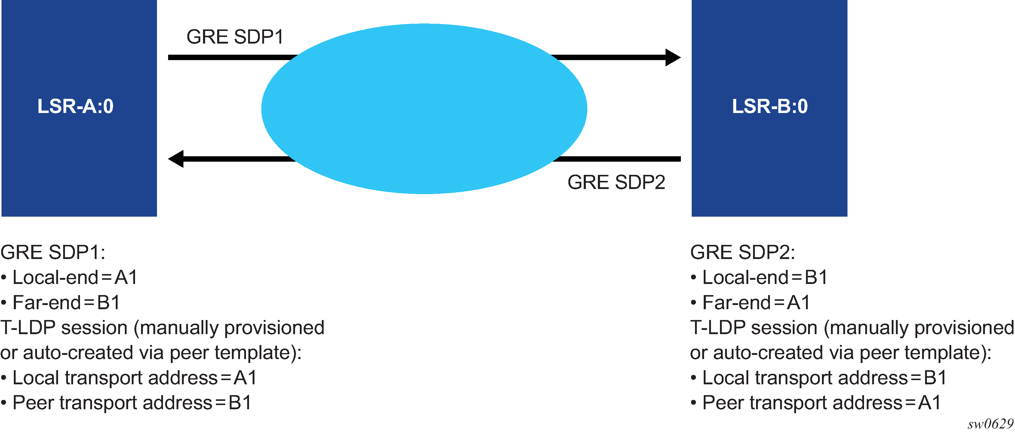
Consequently, if the source transport address used by the T-LDP control plane session does not match the destination transport address set by the remote PE in the targeted LDP Hello messages, the T-LDP session does not come up.
For example, the setup in Mismatched T-LDP control plane parameters results in both GRE SDP1 and SDP2 to remain down because the targeted Hello adjacency and LDP session does not come up between the two LDP LSRs.

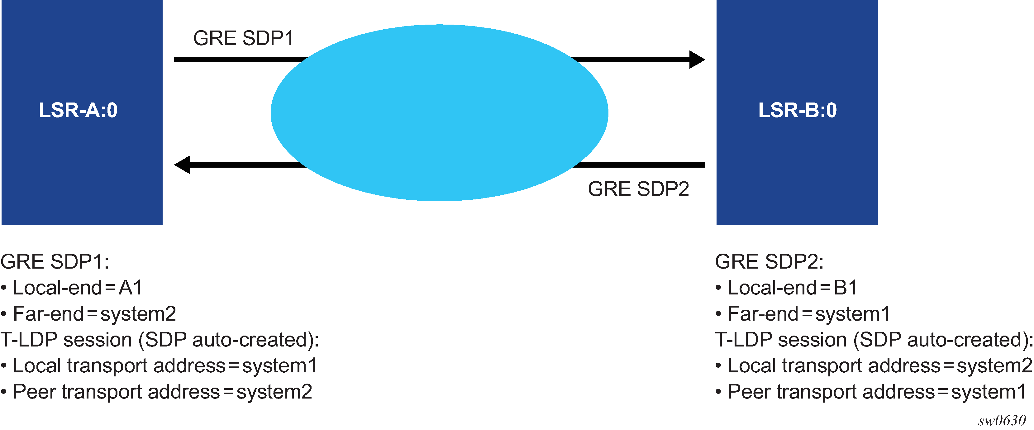
The user must match the local transport address of the T-LDP session to the local-end address of the GRE SDP in both the local and remote PE routers. This can be achieved by manually configuring a T-LDP session to the peer, or by auto-creating a T-LDP session with the targeted peer template feature, and setting the local-lsr-id command to the address configured in the local-end command of the GRE SDP. In addition, the far-end address must be in a GRE termination subnet at the remote PE and be the primary address of an interface in order for T-LDP to use it as its local LSR ID at the remote PE. Proper setting of T-LDP control plane parameters shows an example of a correct configuration.
The source address used by the GRE tunnel in the data plane can be different than the local transport address used by T-LDP in the control plane and the GRE SDPs still come up. For example, the setup in Source address mismatch between control and data planes uses at each end the system address for the T-LDP session but uses a loopback interface address as the source address of the GRE SDP.
The same recommendation applies when the SDP uses BGP for signaling the VC labels of the services. The user must configure the BGP session to the peer and set the local-address CLI command under the BGP group context or under the neighbor context to the address configured in the local-end command of the GRE SDP.
Replies to OAM messages such as an SDP keep-alive and sdp-ping are sent by the far-end PE using the MPLS-over-GRE encapsulation to the source address of the received OAM message. This means, the source transport address of the T-LDP control plane session or the BGP control plane session is used for the signaling of the VC-label in the local PE. Replies to OAM messages when the VC label is static are sent to the source address of the local PE. In all cases however, the system can properly extract them to the CPM as long as the subnet of that local interface is reachable.
GRE SDP tunnel fragmentation and reassembly
GRE SDP tunnel fragmentation and reassembly allows those services for which fragmentation is typically not available to make use of IP layer fragmentation and reassembly of GRE SDP tunnels that carry those services. It enables services that require larger MTUs to be carried over network segments where the MTU is less than the MTU of their respective GRE SDP tunnel packets. As a result, GRE SDP tunnel packets that require fragmentation are either fragmented at the source node or within the MTU restricted network, and reassembled on the GRE SDP terminating node.
GRE SDP tunnel fragmentation is supported on the following platforms:
VSR-I
VSR-a
GRE SDP tunnel fragmentation
The allow-fragmentation command enables GRE SDP tunnel fragmentation and can be configured under the following:
SDP with type GRE (MPLS is not supported)
PW template with auto-gre-sdp
The services that are supported with GRE SDP fragmentation and reassembly include the following:
Epipe VLL services using GRE SDP tunnels
BGP-VPLS
BGP-VPWS
When enabled, GRE SDP tunnel fragmentation is applied to any generated GRE SDP tunnel packet where its size is greater than the MTU of the network interface needed to egress the node. The network interface chosen to egress the node is based on the SDP bindings for the service.
For GRE SDPs and SDP bindings using PW templates with auto-gre-sdp, if a received SAP packet size is greater than the service MTU, the packet is dropped per normal SAP ingress processing.
If GRE-SDP tunnel fragmentation is enabled when configuring allow-fragmentation, the DF-bit is cleared for unfragmented and fragmented GRE SDP tunnel packets. This allows downstream routers to fragment the packets further if needed.
GRE SDP tunnel reassembly
To reassemble GRE SDP tunnel fragments on the node terminating the service carried in the GRE SDP tunnel, the BB-ISA application is used to receive fragments, reassemble them, and return the reassembled GRE SDP tunnel packet for regular ingress processing.
To enable reassembly of GRE SDP fragmented packets, the following items must be configured:
-
Enable the BB-ISA application on the node (see the 7450 ESS, 7750 SR, and VSR Multiservice ISA and ESA Guide for more information).
-
Configure an IP filter, using config>filter>ip-filter with:
-
default-action forward
-
match protocol gre and fragment set to true
-
action set to reassemble
-
-
Configure a NAT group under config>isa>nat-group with the active-mda-limit set to 1 and referencing the mda where the BB-ISA is configured.
-
Add the filter to the router interface or interfaces where GRE SDP packets and fragments are expected to be received.
-
Enable reassembly to base routing by configuring config>router>reassembly group nat-group to-base-network.
For example:
#--bb-isa----------------------------------------------
config
    card 1
        mda 2
            mda-type isa-bb-v
            no shutdown
        exit
        no shutdown
    exit
#--ip-filter----------------------------------------------
    filter
        ip-filter 10 create
            default-action forward
            entry 1 create
                match protocol gre
                    fragment true
                exit
                action
                    reassemble
                exit
            exit
        exit
    exit
#--nat-group----------------------------------------------
    isa
        nat-group 1 create
            active-mda-limit 1
            mda 1/2
            no shutdown
        exit
    exit
#--router-base--------------------------------------------
    router Base
        interface "system"
            address 91.91.91.91/32
            no shutdown
        exit
        interface "to-PE2"
            address 61.61.61.61/24 gre-termination
            port 1/1/11:123
            ingress
               filter ip 10
            exit
            no shutdown
        exit
    exit
exit
NGE considerations
GRE SDP tunnel fragmentation and reassembly is supported in conjunction with NGE. Encryption is applied to the GRE SDP (NGE) tunnel packet before fragmentation on egress and not to each fragment. Decryption occurs after the GRE SDP (NGE) tunnel packet is reassembled by the BB-ISA application and returned to base routing for processing.
GRE SDP tunnel reassembly is supported when the GRE SDP tunnel terminates on the router interface IP address. See GRE SDP termination on router interface IP address for information about GRE SDP termination on a router interface IP address.
GRE SDP termination on router interface IP address
An operator can choose to terminate GRE SDP tunnel packets directly on a router interface IP address. This is enabled by using the config router interface address <IP address> gre-termination command and is supported on the following platforms:
VSR-I
VSR-a
Services that support GRE SDP termination on the router interface IP address include the following:
VPRN services (spoke SDP and auto-bind-tunnel)
T-LDP signaled Ethernet VLL services
T-LDP signaled VPLS services
BGP-VPLS services
BGP-VPWS services
Only GRE SDP tunnel packets that have a destination IP that is equal to the /31 value of the IP address configured on the router interface can terminate on the router interface. For example, if the address is set to 1.2.3.4/24, only the single /31 address 1.2.3.4 is used for the GRE SDP tunnel packet to terminate on. GRE SDP termination on router interface IP addresses is not supported on loopback interfaces.
When T-LDP is used to signal services, the local-lsr-id must be set to the /31 value of the IP address of the router interface used for the GRE SDP tunnel packets to terminate on.
When BGP is used to advertise routes for services, the local-address for BGP sessions must be set to the /31 value of the IP address of the router interface used for the GRE-SDP tunnel packets to terminate on.
SAP and MPLS binding loopback with MAC swap
SAPs and MPLS SDP bindings within Ethernet services, Epipe, and VPLS can be placed into a loopback mode, which allows packets to be looped back toward the source of the traffic. The feature is specific to the entity on which the loopback is configured and is non-disruptive to other SAPs and SDP bindings on the same port or LAG.
Epipe, PBB Epipe, VPLS, and I-VPLS service constructs support both ingress and egress loopbacks on Ethernet SAPs or MPLS SDP bindings.
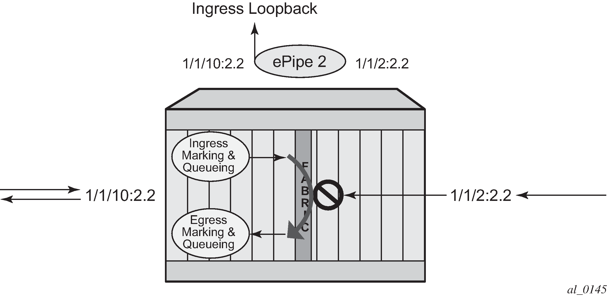
An ingress loopback configured on the entity has the following effects on traffic forwarding on the entity:
-
Traffic arriving on the entity is looped back to the same entity, via the fabric.
-
Traffic attempting to egress that entity from another SAP or SDP binding within the service is blocked.
Essentially an ingress loopback function isolates the SAP or MPLS SDP binding from the rest of the service. Ingress loopback packet processing uses a simple Epipe service example to show the various touch points for a packet that is processed by an ingress loopback as it moves through the network element.
.png)
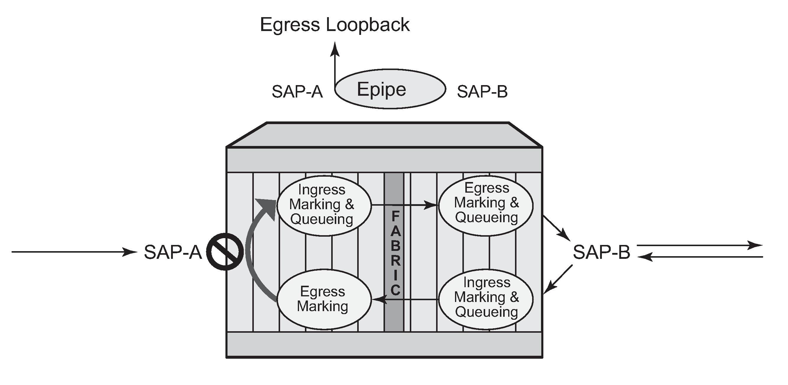
An egress loopback configured on the entity has the following effects on the traffic forwarding on the entity:
-
Traffic arriving on any service SAP or SDP binding that is forwarded to an egress loopback is looped back into the service.
-
Traffic attempting to gain access to the service from that entity (ingress the network element from the entity) is dropped.
In the case of the egress loopback, the SAP or MPLS SDP binding is not isolated from the rest of the service it remains part of the service and reflects traffic back into the service.
Egress loopback packet processing uses a simple Epipe service to illustrate the various touch points for a packet that is processed by an egress loopback as it moves through the network element. Egress processing does not perform queuing functions on the egress; only functions of the forwarding plane like remarking are performed.
The operational state of the SAP or MPLS SDP binding does not change as a result of the loopback function. This means a SAP or MPLS SDP binding that is operationally up does not change state strictly because the loopback started or stopped. Of course control protocols that are attempting to gain access via the entity that is not allowing packets to enter the service eventually time out.
Exercise caution when considering the use of control protocols in a service with enabled loopbacks. The operator must understand that control protocol interruptions can significantly impact the state of the SAP. When SAPs are dynamically created using a protocol or a protocol is required to maintain the operational state of the SAP, interrupting the control protocol causes the SAP to fail. Other SAPs linking their state to a failed SAP react to that failure as well. This loopback function is per Ethernet SAP or MPLS SDP binding. That is, all traffic that is extracted and sent to the CPM before the loopback process is looped back in the direction it was received, or in the case of VPLS, back into the service. All service based control protocols that are included with this service should be removed to ensure the loopback process is handling the packets and not some other function on the node that can extract the control protocol but never respond because the service is blocked. However, there may be instances where it is essential to continue running control protocols for the service during a loopback. For example, Down MEPs on an Ethernet SAP could continue to process ETH-CFM packets if the loopback is on the mate Ethernet SAP and was configured as an egress loopback.
By default, no MAC swap functions are performed. Options are available to support various MAC swap functions. MAC-Swap configuration and options lists the actions and functions based on the configured mac-swap and associated options.
| Configuration | Reflection with inbound DA | ||||
|---|---|---|---|---|---|
| Action | Options | Unicast (learned) | Unicast (unknown) | Broadcast | Multicast |
|
mac-swap |
no options |
Swap SA to DA Swap DA to SA |
Swap SA to DA Swap DA to SA |
Drop |
Drop |
|
mac-swap |
mac |
Swap SA to DA Swap DA to SA |
Swap SA to DA Swap DA to SA |
Swap SA to DA Static MAC= SA |
Swap SA to DA Static MAC= SA |
|
mac-swap |
mac + all |
Swap SA to DA Static MAC= SA |
Swap SA to DA Static MAC= SA |
Swap SA to DA Static MAC= SA |
Swap SA to DA Static MAC= SA |
|
none |
none |
No swapping |
No swapping |
No swapping |
No swapping |
Only the outer Layer 2 header can be manipulated.
In order for the loopback function to operate, the service must be operationally up, and the SAP, port, or LAG must be administratively up. In the case of a LAG, the LAG must have member ports that are administratively up. If any of these conditions are not met, the loopback function fails.
A SAP that is configured for egress loopback is not required to be operationally up, and the cabling does not need to be connected to the port. However, all necessary hardware must be installed in the network element for the ingress packets to be routed to the egress. Ghost ports do not support loopback operations.
An Epipe service enters an operationally down state when one of the SAPs is non-operational. The service state remains or is returned to an operational state if the ignore-oper-down command is configured under the non-operational SAP. A VPLS service remains operational as long as one SAP in the service is operational. However, if the SAP is a VPLS is configured over a LAG, the SAP is removed from the forwarding table if it has a non-operational state, and, consequently, packets never reach the egress. The process-cpm-traffic-on-sap-down command can be configured under the VPLS SAP over a LAG to allow the LAG SAP to be reached even with a non-operational SAP.
If the service state is not operational or the egress SAP is not reachable via the forwarding plane, the traffic never arrives on the SAP to be looped.
MPLS SDP bindings must be operationally up or the loopback function fails.
Use the tools hierarchy to configure this functionality. In this specific case, the loopback tools supporting this functionality may be configured through CLI or through SNMP. However, these commands are never resident in the configuration. This means the loopback survives high availability events that cause one CPM to change from standby to active, as well as ISSU function or IOM resets (hard or soft). However the loopback function does not survive a complete node reboot.
In the case on SNMP, it is possible to configure a static MAC address for the MAC swap function without actually invoking the MAC swap. This is not possible through the CLI.
This function requires a minimum of IOM/IMM.
This feature and functions that use mirroring are mutually exclusive.
Active loopback mode shows of sap 1/1/10:2.2 in service ID 2 (an Epipe) in an active loopback mode with a MAC swap for all broadcast and multicast destined packets.
The following is an example output of the active loopback mode based on Active loopback mode.
show service id 2 base
===============================================================================
Service Basic Information
===============================================================================
Service Id        : 2                   Vpn Id            : 0
Service Type      : Epipe
Name              : (Not Specified)
Description       : (Not Specified)
Customer Id       : 1                   Creation Origin   : manual
Last Status Change: 07/08/2013 09:57:02
Last Mgmt Change  : 07/08/2013 09:56:49
Admin State       : Up                  Oper State        : Up
MTU               : 1514
Vc Switching      : False
SAP Count         : 2                   SDP Bind Count    : 0
Per Svc Hashing   : Disabled
Force QTag Fwd    : Disabled
-------------------------------------------------------------------------------
Service Access & Destination Points
-------------------------------------------------------------------------------
Identifier                               Type         AdmMTU  OprMTU  Adm  Opr
-------------------------------------------------------------------------------
sap:1/1/2:2.2                            qinq         1522    1522    Up   Up
sap:1/1/10:2.2                           qinq         1522    1522    Up   Up
===============================================================================
tools perform service id 2 loopback eth sap 1/1/10:2.2 start ingress mac-swap mac
00:00:00:00:00:88 00:00:00:00:00:88


tools dump service loopback
===============================================================================
Service Ethernet Loopback Points
===============================================================================
Identifier                               Svc ID      Type  Swap    Swap    Oper
                                                           Unicast Mlt/Br
-------------------------------------------------------------------------------
SAP 1/1/10:2.2 qinq                      2           ingr  SA<->DA static  up
-------------------------------------------------------------------------------
No. of Service ethernet loopback points: 1
===============================================================================

tools dump service id 2 loopback sap 1/1/10:2.2
===============================================================================
Service ID 2 SAP 1/1/10:2.2 Loopback
===============================================================================
Identifier (SAP)      : 1/1/10:2.2 qinq
Service ID            : 2
Type                  : Ingress
MAC Swap
  Unicast             : SA<->DA
  Multicast/Broadcast : Static
  Static MAC          : 00:00:00:00:00:88
SAP Oper State        : Up
-------------------------------------------------------------------------------
Sap Statistics
-------------------------------------------------------------------------------
Last Cleared Time     : N/A

                        Packets                 Octets
CPM Ingress           : 491790                  46721290

Forwarding Engine Stats
Dropped               : 0                       0
Off. HiPrio           : 0                       0
Off. LowPrio          : 0                       0
Off. Uncolor          : 0                       0
Off. Managed          : 0                       0

Queueing Stats(Ingress QoS Policy 1)
Dro. HiPrio           : 0                       0
Dro. LowPrio          : 0                       0
For. InProf           : 0                       0
For. OutProf          : 0                       0

Queueing Stats(Egress QoS Policy 1)
Dro. InProf           : 0                       0
Dro. OutProf          : 0                       0
For. InProf           : 0                       0
For. OutProf          : 0                       0
-------------------------------------------------------------------------------
===============================================================================
To stop the loopback, a simple stop command is required.
tools perform service id 2 loopback eth sap 1/1/10:2.2 stop
Promiscuous ETH-LBM mode of operation
ETH-CFM MEPs support the processing of ETH-CFM PDUs without interrupting the flow of service data. ETH-CFM processing identifies, processes, and responds to the appropriate ETH-CFM PDUs directed at the target MEP using domain-level logic comparison, equal to and lower. This behavior lends itself well to the testing of connectivity, performance monitoring, and path information. The pinpoint ETH-CFM processing logic also lends itself well to service activation testing streams encapsulated in ETH-LBM frames.
The lbm-svc-act-responder configuration option allocates additional resources to the associated MEP to process high-speed service activation streams encapsulated in ETH-LBM frames. When a MEP is created with this option, it streamlines the processing of the inbound ETH-LBM frame. This is accomplished by performing basic ETH-CFM header parsing, replacing the inbound ETH-LBM operational code (03) with the outbound ETH-LBR operational code (02), swapping source and destination MAC addresses, and reflecting any Data TLVs and other data contained in the PDU without validation. A MEP configured with the lbm-svc-act-responder configuration option operates in promiscuous ETH-LBM mode.
Promiscuous ETH-LBM mode bypasses some checks and extended functions typically performed by a MEP. In this mode, the MEP does not validate the Layer 2 destination MAC address of the arriving ETH-LBM frame to ensure that it matches the MEP. ETH-LB system statistics and per-MEP statistics, as well as ETH-LB specific counters, are not incremented. CFM debugging is not available for these ETH-LB packets.
Only ETH-LBM PDUs at the same domain level as the MEP that is configured with the lbm-svc-act-responder function access the additional resources required to accommodate high-speed service activation processing. Normal processing of ETH-CFM packets occurs for all other ETH-CFM PDUs that arrive on the MEP with the same domain level. The MEP also processes and terminates the lower levels as per normal processing. To ensure correct handling of the service activation stream encapsulated in the ETH-LBM PDU, the level of all ETH-LBM packets in the stream must equal that of the target MEP with the lbm-svc-act-responder command.
The ETH-CFM level of the high-speed ETH-LBM stream must match the level of a MEP configured with the lbm-svc-act-responder command. It must not target any lower ETH-CFM level that the MEP terminates. When the service activation test is complete, the MEP can be returned to standard processing by removing this command. If there is available bandwidth, the MEP responds to other ETH-CFM PDUs, such as ETH-DMM marker packets, using standard processing.
This mode of operation is supported for Up and Down MEPs in Epipe and VPLS services as well as for base router interfaces. This functionality requires a minimum of FP3 hardware.
There is interaction between the lbm-svc-act-responder command and the tools perform service id loopback eth command. Nokia recommends that either the lbm-svc act-responder or the tools perform service id loopback eth command be used at any time within a service. If both commands must be configured, and the target reflection point is the MAC Swap Loopback function, the inbound stream of data must not include ETH-CFM traffic that is equal to or lower than the domain level of any configured MEP which would otherwise extract and process the ETH-CFM message.
If the reflection target is a MEP configured with the lbm-svc-act-responder command, the mode (ingress or egress) of the SAP or SDP specified with the tools command and the MEP direction (up or down) must match when the functions are enabled on the same reflection point. The domain level of the inbound ETH-LBM must be the same as that of the MEP configured with lbm-svc-act-responder. At no time should the two functions be conflicting with each other along the path of the stream. Such a conflict can lead to unpredictable and possibly destabilizing situations.