Configuring physical ports with CLI
This section provides information to configure cards, MDAs, and ports.
Preprovisioning guidelines
SR OSs have a console port, either located on the CPM or CCM, or integrated into the chassis (on the 7750 SR-c4 models), to connect terminals to the router.
Configure parameters from a system console connected to a router console port, using Telnet to access a router remotely or SSH to open a secure shell connection.
Predefining entities
To initialize a card, the chassis slot, line card type, and MDA type must match the preprovisioned parameters. In this context, preprovisioning means to configure the entity type (such as the card type, MDA type, port, and interface) that is planned for a chassis slot, card, or MDA. Preprovisioned entities can be installed but not enabled or the slots can be configured but remain empty until populated. Provisioning means that the preprovisioned entity is installed and enabled.
You can:
Preprovision ports and interfaces after the line card and MDA types are specified.
Install line cards in slots with no pre-configuration parameters specified. After the card is installed, the card and MDA types must be specified.
Install a line card in a slot provisioned for a different card type (the card does not initialize). The existing card and MDA configuration must be deleted and replaced with the current information.
Preprovisioning a port
Before a port can be configured, the slot must be preprovisioned with an allowed card type and the MDA must be preprovisioned with an allowed MDA type. Some recommendations to configure a port include:
Ethernet
-
Configure an access port for customer facing traffic on which services are configured.
-
An encapsulation type may be specified to distinguish services on the port or channel. Encapsulation types are not required for network ports.
-
To configure an Ethernet access port, see Ethernet access port.
-
SONET/SDH
-
SONET/SDH can be used only when configuring OC-3 and OC-12 SONET paths.
-
To configure a SONET path, see Configuring SONET/SDH port parameters.
-
Configure a network port or channel to participate in the service provider transport or infrastructure network.
-
Accounting policies can only be associated with network ports/channels and Service Access Ports (SAPs). Accounting policies are configured in the config>log> accounting-policy context.
-
To configure an Ethernet network port, see Ethernet network port.
-
channelized
Channelized ports can only be configured on TDM satellites such as the channelized OC-3-SFP or channelized OC-12-SFP.
Maximizing bandwidth use
After ports are preprovisioned, Link Aggregation Groups (LAGs) can be configured to increase the bandwidth available between two nodes.
All physical links or channels in a LAG/bundle combine to form one logical connection. A LAG/bundle also provides redundancy in case one or more links that participate in the LAG/bundle fail. To configure channelized port for Sonet/SDH high speed channels (ASAP MDAs only), see Configuring SONET/SDH port parameters. For command syntax for LAG, see Configuring LAG parameters.
Basic configuration
The most basic configuration must specify the following:
chassis slot
line card type (must be an allowed card type)
MDA slot
MDA (must be an allowed MDA type)
specific port to configure
The following is an example of card configuration for the 7750 SR:
-
classic CLI configuration
A:Dut-B# admin display-config | match "Card Configuration" post-lines 22 echo "Card Configuration" #-------------------------------------------------- card 6 card-type iom4-e no shutdown exit card 7 card-type iom4-e mda 1 mda-type me10-10gb-sfp+ no shutdown exit mda 2 mda-type me1-100gb-cfp2 no shutdown exit no shutdown exit card 8 card-type iom4-e no shutdown exit #-------------------------------------------------- -
MD-CLI configuration
A:admin@Dut-B# info
    configure {
        card 6 {
            card-type iom4-e
            mda 1 {
                mda-type me1-100gb-cfp2
            }
            fp 1 {
            }
        }
        card 7 {
            card-type iom4-e
            mda 1 {
                mda-type me10-10gb-sfp+
            }
            mda 2 {
                mda-type me1-100gb-cfp2
            }
            fp 1 {
            }
        }
        card 8 {
            card-type iom4-e
            mda 1 {
                mda-type me10-10gb-sfp+
            }
        }
The following is an example of card configurations for the 7950 XRS:
A:7950 XRS-20# configure card 1
A:7950 XRS-20>config>card# info
----------------------------------------------
        card-type xcm-x20
        mda 1
            mda-type cx20-10g-sfp
            no shutdown
        exit
        mda 2
            mda-type cx2-100g-cfp
            no shutdown
        exit
        no shutdown
----------------------------------------------
Common configuration tasks
The following sections are basic system tasks that must be performed.
Configuring cards and MDAs
Card configurations include a chassis slot designation. A slot must be preconfigured with the type of cards and MDAs which are allowed to be provisioned.
The following example shows card and MDA configurations for the 7750 SR or 7450 ESS:
-
classic CLI commands
echo "Card Configuration" #-------------------------------------------------- card 8 card-type iom4-e mda 1 mda-type me10-10gb-sfp+ no shutdown exit mda 2 mda-type me1-100gb-cfp2 no shutdown exit no shutdown exit #---------------------------------------------- -
MD-CLI commands
(gl)[/]
A:admin@Dut-E# configure card 8

(gl)[/configure card 8]
A:admin@Dut-E# info
    card-type iom4-e
    mda 1 {
        mda-type me10-10gb-sfp+
    }
    mda 2 {
        mda-type me1-100gb-cfp2
    }
    fp 1 {
    }
The following example shows card configurations for the 7950 XRS:
A:7950 XRS-20# configure card 1
A:7950 XRS-20>config>card# info
----------------------------------------------
        card-type xcm-x20
        mda 1
            mda-type cx20-10g-sfp
            no shutdown
        exit
        mda 2
            mda-type cx2-100g-cfp
            no shutdown
        exit
        no shutdown
----------------------------------------------
Configuring FP network pool parameters
FP-level pools are used by ingress network queues. Network policies can be applied (optional) to create and edit QoS pool resources for ingress network queues. Network-queue and slope policies are configured in the config>qos context.
The following example shows an FP pool configuration for 7750 SR or 7450 ESS:
*A:PE>config>card>fp# info
----------------------------------------------
            ingress
                network
                    pool "default"
                        resv-cbs 50
                        slope-policy "slope1"
                    exit
                    queue-policy "10"
                exit
            exit
----------------------------------------------
*A:PE>config>card>fp#
Configuring ports
This section provides the CLI syntax and examples to configure port parameters.
Configuring port pool parameters
The buffer space is portioned out on a per port basis. Each port gets an amount of buffering which is its fair-share based on the port’s bandwidth compared to the overall active bandwidth.
This mechanism takes the buffer space available and divides it into a portion for each port based on the port’s active bandwidth relative to the amount of active bandwidth for all ports associated with the buffer space. The number of ports sharing the same buffer space depends on the type of MDAs populated on the IOM. An active port is considered to be any port that has an active queue associated. After a queue is created for the port, the system allocates the appropriate amount of buffer space to the port. This process is independently performed for both ingress and egress.
Normally, the amount of active bandwidth is considered as opposed to total potential bandwidth for the port when determining the port’s fair share. If a port is channelized and not all bandwidth is allocated, only the bandwidth represented by the configured channels with queues configured is counted toward the bandwidth represented by the port. Also, if a port may operate at variable speeds (as in some Ethernet ports), only the current speed is considered. Based on the above, the number of buffers managed by a port may change because of queue creation and deletion, channel creation and deletion and port speed variance on the local port or other ports sharing the same buffer space.
After the active bandwidth is calculated for the port, the result may be modified through the use of the ing-percentage-of-rate and egr-percent-of-rate commands. The default value of each is 100% which allows the system to use all of the ports active bandwidth when deciding the relative amount of buffer space to allocate to the port. When the value is explicitly modified, the active bandwidth on the port is changed according to the specified percentage. If a value of 50% is given, the ports active bandwidth is multiplied by 5, if a value of 150% is given, the active bandwidth is multiplied by 1.5. The ports rate percentage parameters may be modified at any time.
Examples:
-
To modify (in this example, to double) the size of buffer allocated on ingress for a port:
B:SR7-10# configure port 1/2/1 modify-buffer-allocation-rate ing-percentage-of-rate 200 -
To modify (in this example, to double) the size of buffer allocated on egress for a port:
B:SR7-10# configure port 1/2/1 modify-buffer-allocation-rate egr-percentage-of-rate 200
The default buffer allocation has the following characteristics:
Each port manages a buffer according to its active bandwidth (ports with equal active bandwidth get the same buffer size).
An access port has 2 default pools created: access-ingress and access-egress.
A network port has 2 default pools created: ingress-FP (common pool for all ingress network ports) and network-egress.
All queues defined for a port receive buffers from the same buffer pool.
The following example shows port pool configurations:
A:ALA-B>config>port# info
----------------------------------------------
        access
            egress
                pool
                    slope-policy "slopePolicy1"
                exit
            exit
        exit
        network
            egress
                pool
                    slope-policy "slopePolicy2"
                exit
            exit
        exit
        no shutdown
----------------------------------------------
The following shows a CBS configuration over subscription example:
*A:Dut-T>config>port# info
----------------------------------------------
        access
            ingress
                pool
                    amber-alarm-threshold 10
                    resv-cbs 10 amber-alarm-action step 1 max 30
                exit
            exit
        exit
        ethernet
            mode access
            encap-type dot1q
        exit
        no shutdown
Changing hybrid-buffer-allocation
The following example shows a hybrid-buffer-allocation value change (from default) for ingress. In this example, the network-egress buffer pool is two times the size of the access-egress.
A:SR>config>port>hybrid-buffer-allocation# info
----------------------------------------------
egr-weight access 20 network 40
Changing APS parameters
APS configuration rules:
A working port must be added first. Then a protection port can be added or removed at any time.
A protection port must be shutdown before being removed from an APS group.
A path cannot be configured on a port before the port is added to an APS group.
A working port cannot be removed from an APS group until the APS port path is removed.
When ports are added to an APS group, all path-level configurations are available only on the APS port level and configuration on the physical member ports are blocked.
For a multi-chassis APS group, only one member circuit (either working or protect) can be added. Note that the neighbor IP address of an APS group must be configured before adding a member circuit in it. The configuration of a non-zero neighbor IP address indicates the APS group as multi-chassis. Thus, the member circuit and services must be removed before adding or removing the neighbor IP address (for example, before converting an APS group from multi-chassis to single-chassis or single-chassis to multi-chassis).
The following shows an example configuration for a TDM SC-APS group using SONET/SDH channelization, and a Cpipe service using an APS SAP and a physical TDM SAP:
A:ALA-274>config# port (1/1/1)
----------------------------------------------
    sonet-sdh
        speed oc3
    exit
    no-shutdown
----------------------------------------------
A:ALA-274>config>port# aps-1
----------------------------------------------
    aps
        working-circuit tsat-1/1/2
            protect-circuit tsat-20/1/4
    exit
    sonet-sdh
            path sts1-1
            exit
            path sts1-3
            exit
            path vt15-1.1.1
            exit
            path vt15-3.7.4
            exit
        exit
        tdm
            ds1 1.1.1
                framing ds1-unframed
                clock-source node-timed
                channel-group 1
                exit
            exit
            ds1 3.7.4
                framing ds1-unframed
                clock-source node-timed
                channel-group 1
                exit
            exit
        exit
    exit
    no-shutdown
    exit
----------------------------------------------
A:ALA-274>cpipe 221 customer 1 vc-type satop-t1 create
            sap aps-100.1.1.1.1 create
            exit
            sap tsat-1/1/1.1.1.1.1 create
            exit
        exit
The following shows an example of the configuration for the working circuit/node of an MC-APS group:
A:ALA-274>config>port (10/1/3)# info
----------------------------------------------
        description "APS Group"
        aps
            neighbor 192.0.2.2
            working-circuit tsat-10/1/3
        exit
        no shutdown
----------------------------------------------
A:ALA-274>config>port#
The following shows an example of the configuration for the protect circuit/node of an MC-APS group:
A:ALA-274>config>port (20/1/4)# info
----------------------------------------------
        description "APS Group"
        aps
            neighbor 192.0.2.1
            protect-circuit tsat-20/1/4
        exit
        no shutdown
----------------------------------------------
A:ALA-274>config>port#
Configuring Ethernet port parameters
Ethernet network port
A network port is network facing and participates in the service provider transport or infrastructure network processes.
The following example shows a network port configuration:
A:ALA-B>config>port# info
----------------------------------------------
        description "Ethernet network port"
        ethernet
        exit
        no shutdown
----------------------------------------------
A:ALA-B>config>port#
Ethernet access port
Services are configured on access ports used for customer-facing traffic. If a Service Access Port (SAP) is to be configured on a port, it must be configured as access mode. When a port is configured for access mode, the appropriate encapsulation type can be specified to distinguish the services on the port. After a port has been configured for access mode, multiple services may be configured on the port.
The following example shows an Ethernet access port configuration:
A:ALA-A>config>port# info
----------------------------------------------
        description "Ethernet access port"
        access
            egress
                pool
                    slope-policy "slopePolicy1"
                exit
            exit
        exit
        network
            egress
                pool
                    slope-policy "slopePolicy2"
                exit
            exit
        exit
        ethernet
            mode access
            encap-type dot1q
        exit
        no shutdown
----------------------------------------------
A:ALA-A>config>port#
Configuring 802.1x authentication port parameters
The following example shows an 802.1x port configuration:
A:ALA-A>config>port>ethernet>dot1x# info detail
----------------------------------------------
                 port-control auto
                 radius-plcy dot1xpolicy
                 re-authentication
                 re-auth-period 3600
                 max-auth-req 2
                 transmit-period 30
                 quiet-period 60
                 supplicant-timeout 30
                 server-timeout 30
                 no tunneling
----------------------------------------------
Configuring SONET/SDH port parameters
Only the TDM satellite has native SONET/SDH ports.
When an Ethernet port is configured in WAN mode (xgig wan), you can change specific SONET/SDH parameters to reflect the SONET/SDH requirements for this port.
The following CLI output shows an example of a SONET/SDH configuration for a WAN PHY Ethernet port:
*A:7950 XRS-20>config>port# info
----------------------------------------------
        shutdown
        ethernet
            xgig wan
        exit
        sonet-sdh
            tx-dus
            suppress-lo-alarm
            threshold ber-sd rate 4
            section-trace increment-z0
            path
                trace-string "hello"
                report-alarm pais
                signal-label 0x20
            exit
        exit
----------------------------------------------
Configuring channelized ports
When configuring channelized ports, the port ID is specified in different ways depending on the level of channelization. Ethernet ports cannot be channelized. Channelization options available on the 7750 SR channelized MDAs lists the channelization options and port syntax available on the 7750 SR channelized MDAs.
| Framing | Channelization/mapping option | Channelized MDAs supporting services on the port/channel |
|---|---|---|
|
Up to 2,048 kb/s (n*DS0 within E1 up to E1) |
||
|
SDH |
STM4>AUG4>AUG1>VC4>TUG3>TUG2>VC12 |
TDM satellite configured in mode t1-chstm4-sfp |
|
SDH |
STM4>AUG4>AUG1>VC3>TUG2>VC12 |
TDM satellite configured in mode ts4-chstm1-sfp |
|
Up to 1,544 kb/s (n*DS0 within DS1 up to DS1) |
||
|
SDH |
STM4>AUG4>AUG1>VC4>TUG3>TUG2>TU11>VC11 |
TDM satellite configured in mode ts1-chstm4-sfp |
|
SDH |
STM4>AUG4>AUG1>VC4>TUG3>TUG2>TU12>VC11 |
None |
|
SDH |
STM4>AUG4>AUG1>VC3>TUG2>VC11 |
TDM satellite configured in mode ts4-chstm1-sfp |
|
SONET |
OC12>STS12>STS1 SPE>VT GROUP>VT1.5 SPE |
TDM satellite configured in mode ts1-choc12-sfp or in mode ts4-choc3-sfp |
A port ID for channels has one of the following syntax as applicable to channelization and mapping options where the port configuration syntax is slot/mda/port (Channelized port syntax examples).
| Port ID for physical port speed | |||
|---|---|---|---|
| Channel speed | OC12/STM4 | OC3/STM1 | DS3/E3 |
SONET/SDH |
|||
STS3/STM1 |
port.sts3-{1 to 4} |
port.sts3 |
— |
STS1/STM0 |
port.sts1-{1 to 4}.{1 to 3} |
port.sts1-{1 to 3} |
— |
TUG3 |
port.tug3-{1 to 4}.{1 to 3} |
port.tug3-{1 to 3} |
— |
| VT15/VC1.11 | port.vt15-{1 to 4}.{1 to 3}.{1 to 4}.{1 to 7} |
port.vt15-{1 to 3}.{1 to 4}.{1 to 7} |
— |
| VT2/VC12 1 | port.vt2-{1 to 4}.{1 to 3}.{1 to 3}.{1 to 7} |
port.vt2-{1 to 3}.{1 to 3}.{1 to 7} |
— |
TDM |
|||
DS1 in VT2 |
port.{1 to 4}.{1 to 3}.{1 to 3}.{1 to 7} |
port.{1 to 3}.{1 to 3}.{1 to 7} |
— |
DS1 in VT15 |
port.{1 to 4}.{1 to 3}.{1 to 4}.{1 to 7} |
port.{1 to 3}.{1 to 4}.{1 to 7} |
— |
E1 in VT2 |
port.{1 to 4}.{1 to 3}.{1 to 3}.{1 to 7} |
port.{1 to 3}.{1 to 3}.{1 to 7} |
— |
Verify the MDA type
To ensure that you have a channel-capable MDA, verify that the MDA-type you are configuring by entering a show mda slot-id command.
The MDAs shown in the MDA Provisioned column in the following output are a 12-port channelized DS3 MDA (m12-ds3) on card 1, MDA slot 1, and a 1-port channelized OC12-SFP MDA (m1-choc12-sfp) on card 1, MDA slot 2.
A:ALA-A# show mda 1
===============================================================================
MDA 1/1
===============================================================================
Slot  Mda   Provisioned           Equipped              Admin     Operational
            Mda-type              Mda-type              State     State
-------------------------------------------------------------------------------
1     1     m12-ds3               m12-ds3               up        provisioned
===============================================================================
ALA-A# show mda 2
===============================================================================
MDA 1/2
===============================================================================
Slot  Mda   Provisioned           Equipped              Admin     Operational
            Mda-type              Mda-type              State     State
-------------------------------------------------------------------------------
1     2     m1-choc12-sfp         m1-choc12-sfp         up        provisioned
===============================================================================
A:ALA-A#
Configuring a channelized OC-12-SFP port
Channelized OC-12 port structure shows the logic of the channelized OC-12 port configuration.
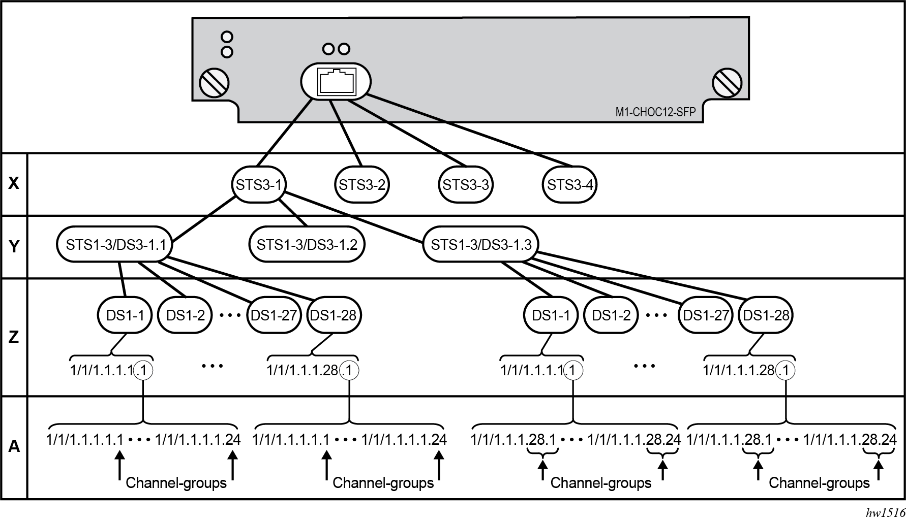
The following shows an example to configure a channelized port on a 1-port channelized OC-12-SFP MDA:
ALA-A>config# port 5/2/1
At this level you must choose the tributary. When provisioning nodes on a channelized OC-12 MDA, you must provision the parent STS1-1 SONET path first.
A:ALA-A>config>port# sonet-sdh
A:ALA-A>config>port>sonet-sdh# path sts1-1.1
A:ALA-A>config>port>sonet-sdh>path# no shutdown
A:ALA-A>config>port>sonet-sdh>path# exit
The following shows the output:
A:ALA-A>config>port>sonet-sdh# info
----------------------------------------------
        sonet-sdh
            path sts1-1.1
                no shutdown
            exit
        exit
----------------------------------------------
A:ALA-A>config>port>sonet-sdh#
To set the channelized mode on a port, the parameter must be in a shutdown state. Clear channel uses out-of-band signaling, not in-band signaling, so the channel's entire bit rate is available. Channelized ports use in-band signaling and must be explicitly enabled.
A:ALA-A>config>port# tdm
A:ALA-A>config>port>tdm# ds1 1.1.1
A:ALA-A>config>port>tdm>ds1# shutdown
A:ALA-A>config>port>tdm>ds1# channelized ds1
A:ALA-A>config>port>tdm>ds1# no shutdown
A:ALA-A>config>port>tdm>ds1# exit
The following shows an example of the output:
A:ALA-A>config>port# info
----------------------------------------------
        sonet-sdh
            path sts3-1
                no shutdown
            exit
            path sts1-1.1
                no shutdown
            exit
        exit
        no shutdown
----------------------------------------------
A:ALA-A>config>port#
In the TDM context, configure channel groups parameters. 24 timeslots can be configured per channel group.
A:ALA-A>config>port>tdm# ds1 1.1.1
A:ALA-A>config>port>tdm>ds1# no shutdown
A:ALA-A>config>port>tdm>ds1# channel-group 1
A:ALA-A>config>port>tdm>ds1>channel-group# timeslots 1
A:ALA-A>config>port>tdm>ds1>channel-group# no shutdown
A:ALA-A>config>port>tdm>ds1>channel-group# exit
A:ALA-A>config>port>tdm>ds1# no shutdown
A:ALA-A>config>port>tdm>ds1# channel-group 2
A:ALA-A>config>port>tdm>tds1>channel-group# timeslots 2
A:ALA-A>config>port>tdm>ds1>channel-group# no shutdown
A:ALA-A>config>port>tdm>ds1>channel-group# exit
A:ALA-A>config>port>tdm>ds1# exit


A:ALA-A>config>port>tdm# info
----------------------------------------------
        sonet-sdh
            path sts3-1
                no shutdown
            exit
            path sts1-1.1
                no shutdown
            exit
        exit
        tdm
            ds1 ds1-1.1.1
                channel-group 1        (see SAP 5/2/1.1.1.1.1 below)
                    timeslots 1
                    no shutdown
                exit
                channel-group 2        (see SAP 5/2/1.1.1.1.2 below)
                    timeslots 2
                    no shutdown
                exit
                no shutdown
            exit
        exit
        no shutdown
----------------------------------------------
A:ALA-A>config>port>tdm#
Services can be applied to the configured channelized ports. The following example shows the CLI usage to configure a customer IES service with interface SAPs on the channelized ports. See the 7450 ESS, 7750 SR, 7950 XRS, and VSR Services Overview Guide for information about how to configure services.
A:ALA-A>config>service# ies 104 customer 1 create
A:ALA-A>config>service>ies$ interface testA create
A:ALA-A>config>service>ies>if$ address 192.168.1.1/24
A:ALA-A>config>service>ies>if# sap 5/2/1.1.1.1.1 create
A:ALA-A>config>service>ies>if>sap$ exit
A:ALA-A>config>service>ies>if# no shutdown
A:ALA-A>config>service>ies>if# exit
A:ALA-A>config>service>ies# interface testB create
A:ALA-A>config>service>ies>if$ address 192.168.2.1/24
A:ALA-A>config>service>ies>if# sap 5/2/1.1.1.1.2 create
A:ALA-A>config>service>ies>if>sap$ exit
A:ALA-A>config>service>ies>if# no shutdown
A:ALA-A>config>service>ies>if# exit
A:ALA-A>config>service>ies# no shutdown
The following output shows the channelized ports 5/2/1.1.1.1.1 and 5/2/1.1.1.1.2) applied to SAPs on the IES service configuration:
A:ALA-A>config>service>ies# info
----------------------------------------------
            interface "testA" create
                address 192.168.1.1/24
                sap 5/2/1.1.1.1.1 create
                exit
            exit
            interface "testB" create
                address 192.168.2.1/24
                sap 5/2/1.1.1.1.2 create
                exit
            exit
            no shutdown
----------------------------------------------
A:ALA-A>config>service>ies#
Configuring channelized STM1/OC3 parameters
The following example shows basic syntax to configure channelized STM1/OC3 parameters:
config# port port-id
    — sonet-sdh
        — framing {sonet | sdh}
        — group sonet-sdh-index payload {tu3 | vt2 | vt15}
        — path [sonet-sdh-index]
            — payload {sts3 | tug3 | ds3 | e3}
            — trace-string [trace-string]
            — no shutdown
config# port 5/2/1
    — config>port# sonet-sdh
    — config>port>sonet-sdh# framing sdh
    — config>port>sonet-sdh# path sts3
    — config>port>sonet-sdh>path# trace-string "HO-path"
    — config>port>sonet-sdh>path# exit
    — config>port>sonet-sdh# group tug3-1 payload vt2
    — config>port>sonet-sdh# group tug3-3 payload vt2
    — config>port>sonet-sdh# path vt2-1.1.1
    — config>port>sonet-sdh>path# trace-string "LO-path 3.7.3"
    — config>port>sonet-sdh>path# no shutdown
    — config>port>sonet-sdh>path# exit
    config>port>sonet-sdh#	 exit
    config>port# tdm
    config>port>tdm# e1 1.1.1
    config>port>tdm>e1# channel-group 1
    config>port>tdm>e1>channel-group# timeslots 2-32
    config>port>tdm>e1>channel-group# no shutdown
    — config>port>tdm>e1>channel-group# exit
    — config>port>tdm# e1 3.7.3
    config>port>tdm>e1# channel-group 2
    config>port>tdm>e1>channel-group# timeslots 2-32
    config>port>tdm>e1>channel-group# no shutdown
    config>port>tdm>e1>channel-group# exit
The following shows the configuration output:
A:ALA-49>config>port# info
------------------------------------------------------------------------------------
        sonet-sdh
            framing sdh
            path sts3
                trace-string "HO-path"
                no shutdown
            exit
            group tug3-1 payload vt2
            group tug3-3 payload vt2
            path vt2-1.1.1
                trace-string "LO-path 3.7.3"
                no shutdown
            exit
            path vt2-3.7.3
                no shutdown
            exit
        exit
        tdm
            e1 1.1.1
                channel-group 1
                    timeslots 2-32
                    no shutdown
                exit
                no shutdown
            exit
            e1 3.7.3
                channel-group 2
                    timeslots 2-32
                    no shutdown
                exit
                no shutdown
            exit
        exit
        no shutdown
----------------------------------------------
Example Cpipe port configurations
Before a Cpipe service can be provisioned, the following entities must be configured:
Configuring a DS1 port
The following shows an example of a DS1 port configured for CES:
A:sim216#  show port 1/5/1.1.3.1
===============================================================================
TDM DS1 Interface
===============================================================================
Description        : DS1
Interface          : 1/5/1.1.3,1
Type               : ds1                     Framing              : esf
Admin Status       : up                      Oper Status          : up
Physical Link      : yes                     Clock Source         : loop-timed
Signal Mode        : none
Last State Change  : 10/31/2006 14:23:12     Channel IfIndex      : 580943939
Loopback           : none                    Invert Data          : false
Remote Loop respond: false                   In Remote Loop       : false
Load-balance-algo  : default                 Egr. Sched. Pol      : n/a
BERT Duration      : N/A                     BERT Pattern         : none
BERT Synched       : 00h00m00s               Err Insertion Rate   : 0
BERT Errors        : 0                       BERT Status          : idle
BERT Total Bits    : 0
Cfg Alarm          : ais los
Alarm Status       :
===============================================================================
Configuring a channel group
The following shows an example of a DS1 channel group configured for CES:
A:sim216#  show port 1/5/1.1.3.1
===============================================================================
TDM DS0 Chan Group
===============================================================================
Description        : DS0GRP
Interface          : 1/5/1.1.3.1
TimeSlots          : 1-12
Speed              : 64                      CRC                  : 16
Admin Status       : up                      Oper Status          : up
Last State Change  : 10/31/2006 14:23:12     Chan-Grp IfIndex     : 580943940
Configured mode    : access                  Encap Type           : cem
Admin MTU          : 4112                    Oper MTU             : 4112
Physical Link      : Yes                     Bundle Number        : none
Idle Cycle Flags   : flags                   Load-balance-algo    : default
Egr. Sched. Pol    : n/a
===============================================================================
A:sim216#
Configuring OTU port parameters
The following example shows an OTU port configuration:
*A:ALA-A>config>port>otu# info detail
----------------------------------------------
           otu2-lan-data-rate 11.049
           sf-sd-method fec
           sf-threshold 5
           sd-threshold 7
           fec enhanced
           no report-alarm otu-ais otu-ber-sd otu-tim otu-iae otu-biae fec-sd
           no report-alarm fec-fail fec-uncorr odu-ais odu-oci odu-lck odu-bdi
           no report-alarm odu-tim opu-plm
           report-alarm loc los lof lom otu-ber-sf otu-bdi fec-sf
           sm-tti
               tx auto-generated
               expected auto-generated
               no mismatch-reaction
           exit
           pm-tti
               tx auto-generated
               expected auto-generated
               no mismatch-reaction
           exit
           psi-payload
               tx auto
               expected auto
               no mismatch-reaction
           exit
----------------------------------------------
The following example shows the show port portId otu detail for the default OTU configuration as shown above:
*A:ALA-A# show port 3/2/1 otu detail

===============================================================================
OTU Interface
===============================================================================
OTU Status         : Enabled                    FEC Mode         : enhanced
Async Mapping      : Disabled                   Data Rate        : 11.049 Gb/s

Cfg Alarms         : loc los lof lom otu-ber-sf otu-bdi fec-sf
Alarm Status       :
SF/SD Method       : FEC                        SF Threshold     : 1E-5
                                                SD Threshold     : 1E-7

SM-TTI Tx (auto)   : ALA-A:3/2/1/C44
SM-TTI Ex (bytes)  : (Not Specified)
SM-TTI Rx          : ALA-A:5/2/1/C34
OTU-TIM reaction   : none

PM-TTI Tx (auto)   : ALA-A:3/2/1/C44
PM-TTI Ex (bytes)  : (Not Specified)
PM-TTI Rx          : ALA-A:5/2/1/C34
ODU-TIM reaction   : none

PSI-PT Tx (auto)   : 0x03 (syncCbr)
PSI-PT Ex (auto)   : 0x03 (syncCbr)
PSI-PT Rx          : 0x03 (syncCbr)
OPU-PLM reaction   : none
===============================================================================
OTU Statistics
===============================================================================
Elapsed Seconds                                                10
-------------------------------------------------------------------------------
Near End Statistics                                     Count
-------------------------------------------------------------------------------
FEC Corrected 0s                                                0
FEC Corrected 1s                                                0
FEC Unrrectable Sub-rows                                        0
FEC ES                                                          0
FEC SES                                                         0
FEC UAS                                                         0
Pre-FEC BER                                             0.000E+00
Post-FEC BER                                            0.000E+00
-------------------------------------------------------------------------------
SM BIP8                                                         0
SM ES                                                           0
SM SES                                                          0
SM UAS                                                          0
SM-BIP8-BER                                             0.000E+00
-------------------------------------------------------------------------------
PM BIP8                                                         0
PM ES                                                           0
PM SES                                                          0
PM UAS                                                          0
PM-BIP8-BER                                             0.000E+00
-------------------------------------------------------------------------------
NPJ                                                             0
PPJ                                                             0

-------------------------------------------------------------------------------
Far End Statistics                                      Count
-------------------------------------------------------------------------------
SM BEI                                                          0
PM BEI                                                          0
===============================================================================
The window over which the Bit Error Rate (BER) determined is based on the configured threshold level. The higher the error rate the shorter the window and as the error rate decreases the window increases. Configured BER thresholds and window lengths lists the configured BER thresholds and corresponding window lengths.
| Configured BER threshold | Window length |
|---|---|
10^-3 |
8ms |
10^-4 |
8ms |
10^-5 |
8ms |
10^-6 |
13ms |
10^-7 |
100ms |
10^-8 |
333ms |
10^-9 |
1.66s |
Configuring LAG parameters
LAG configurations should include at least two ports. Other considerations include:
A maximum of 64 ports (depending on the lag-id) can be included in a LAG. All ports in the LAG must share the port characteristics inherited from the primary port.
Autonegotiation must be disabled or set limited mode for ports that are part of a LAG to guarantee a specific port speed.
Ports in a LAG must be configured as full duplex.
The following example shows LAG configuration output:
A:ALA-A>config>lag# info detail
----------------------------------------------
        description "LAG2"
        mac 04:68:ff:00:00:01
        port  1/1/1
        port  1/3/1
        port  1/5/1
        port  1/7/1
        port  1/9/1
        dynamic-cost
        port-threshold 4 action down
----------------------------------------------
A:ALA-A>config>lag#
Configuring BFD on LAG links
BFD can be configured under the LAG context to create and establish the micro-BFD session per link after the LAG and associated links have been configured. An IP interface must be associated with the LAG or a VLAN within the LAG, if dot1q encapsulation is used, before the micro-BFD sessions can be established.
Complete the following steps to enable and configure BFD over the individual LAG links:
When configuring the local and remote IP address for the BFD over LAG link sessions, the local-ip parameter should always match an IP address associated with the IP interface to which this LAG is bound. In addition, the remote-ip parameter should match an IP address on the remote system and should also be in the same subnet as the local-ip address. If the LAG bundle is re-associated with a different IP interface, the local-ip and remote-ip parameters should be modified to match the new IP subnet. The local-ip and remote-ip values do not have to match a configured interface in the case of tagged LAG/ports.
The optional parameters that can be configured for the BFD over LAG links include:
-
Transmit Interval
-
Receive Interval
-
Multiplier
-
Max-Wait-for-Up-Time, this parameter controls how long a link remains active if BFD is enabled after the LAG and associated links are active and in a forwarding state.
-
Max-Time-Admin-Down, this parameter controls how long the system waits before bringing the associated link out of service if an admin down message is received from the far-end.
- Enable BFD within the LAG context, which also enters the CLI into the BFD context.
- Configure the address family which is to be used for the micro BFD sessions. Only one address family can be configured per LAG.
- Configure the local-IP address to be used for the BFD sessions.
- Configure the remote-IP address to be used for the BFD sessions.
The following is an example configuration:
*A:Dut-C>config>lag# info
----------------------------------------------
        bfd
            family ipv4
                local-ip-address 10.120.1.2
                receive-interval 1000
                remote-ip-address 10.120.1.1
                transmit-interval 1000
                no shutdown
            exit
        exit
        no shutdown
Configuring G.8031 protected Ethernet tunnels
Ethernet tunnel configuration can include at most two paths. Other considerations include:
A path contains one member port and one control-tag (backbone VLAN ID/BVID).
If the user wants to replace an existing member port or a control-tag, the whole path needs to be shutdown first. The alternate path is activated as a result keeping the traffic interruption to a minimum. Then the whole path must be deleted and re-created. To replace an existing member port or control tag, the whole path needs to be shutdown first. The alternate path is activated as a result keeping traffic interruption to a minimum. Then the whole path must be deleted, the alternate path precedence modified to primary before re-creating the new path.
The Ethernet tunnel inherits the configuration from the first member port. The following port-level configuration needs to be the same between member ports of an Ethernet tunnel:
config>port>ethernet>access>{ingress|egress}>queue-group
config>port>ethernet>egress-scheduler-policy
config>port>access>egress>pool
config>port>ethernet>dot1q-etype
config>port>ethernet>qinq-etype
config>port>ethernet>pbb-etype
config>port>ethernet> mtu
The user can update these port parameters only if the port is the sole member of an Ethernet tunnel. This means that in the example below, the user needs to remove port 1/1/4 and port 1/1/5 before being allowed to modify 1/1/1 for the above parameters.
eth-tunnel 1
        — path 1
            — member 1/1/1
        — path 2
            — member 1/1/4
    — eth-tunnel 2
        — path 1
            — member 1/1/1
    —      path 2
        —     member 1/1/5
The following example shows eth-tunnel configuration output:
    — port 1/1/1
        — ethernet
            — encap-type dot1q
    — port 2/2/2
        — ethernet
            — encap-type dot1q
        —
    — config eth-tunnel 1
        — path 1
            — member 1/1/1
            — control-tag 100
            — precedence primary
            — eth-cfm
                — mep 51 domain 1 association 1
                — ccm-enable
                — low-priority-defect allDef
                — mac-address 00:AE:AE:AE:AE:AE
                — control-mep
                — no shutdown
        — no shutdown
        — path 2
            — member 2/2/2
            — control-tag 200
    — eth-cfm
        — mep
            — mep 52 domain 1 association 2 direction down
            — ccm-enable
            — low-priority-defect allDef
            — mac-address 00:BE:BE:BE:BE:BE
            — control-mep
            — no shutdown
    — no shutdown
Configuring connectors and connector ports
Some assemblies have support for QSFP28 or QSFP-DD transceiver modules. These modules have different variants, some of which provide multiple physical ports out of a single module (breakout modules). There is a QSFP28 breakout module that supports ten physical 10 Gb Ethernet ports. On assemblies that support these breakout variants, the front panel cages are modeled as connectors instead of as direct ports. The connector must be configured for the type of breakout module that is to be inserted and then the appropriate ports are created and can be configured. The options for breakout on specific connectors depend on both the card type and level (or XMA type and level). See the applicable installation guides for details.
The connector reference is in the format slot/mda/connector (for example, 1/1/c3) and the ports owned by the connector use the format slot/mda/connector/port. For example, in a 7750 SR-1 with the 6-port QSFP28 mda-e-xp installed in the first MDA slot, initially there are no ports available, only six connectors:
A:bkvm18# show mda

===============================================================================
MDA Summary
===============================================================================
Slot  Mda   Provisioned Type                            Admin     Operational
                Equipped Type (if different)            State     State
-------------------------------------------------------------------------------
1     1     me6-100gb-qsfp28                            up        up
*A:bkvm18# show port

===============================================================================
Ports on Slot 1
===============================================================================
Port          Admin Link Port    Cfg  Oper LAG/ Port Port Port   C/QS/S/XFP/
Id            State      State   MTU  MTU  Bndl Mode Encp Type   MDIMDX
-------------------------------------------------------------------------------
1/1/c1        Up    No   Down                 - unkn unkn conn
1/1/c2        Up    No   Down                 - unkn unkn conn
1/1/c3        Up    No   Down                 - unkn unkn conn
1/1/c4        Up    No   Down                 - unkn unkn conn
1/1/c5        Up    No   Down                 - unkn unkn conn
1/1/c6        Up    No   Down                 - unkn unkn conn
===============================================================================
After configuring a module with four 10 Gb breakout ports in connector position 1/1/c1 and a module with one 100 Gb breakout port in connector position 1/1/c2, the physical ports are created:
A:bkvm18# configure port 1/1/c1 connector breakout c4-10g
A:bkvm18# configure port 1/1/c2 connector breakout c1-100g

A:bkvm18>show port
===============================================================================
Ports on Slot 1
===============================================================================
Port          Admin Link Port    Cfg  Oper LAG/ Port Port Port   C/QS/S/XFP/
Id            State      State   MTU  MTU  Bndl Mode Encp Type   MDIMDX
-------------------------------------------------------------------------------
1/1/c1        Up    No   Link Up              - unkn unkn conn   40GBASE-SR4
1/1/c1/1      Down  No   Down    9212 9212    - netw null xgige
1/1/c1/2      Down  No   Down    9212 9212    - netw null xgige
1/1/c1/3      Down  No   Down    9212 9212    - netw null xgige
1/1/c1/4      Down  No   Down    9212 9212    - netw null xgige
1/1/c2        Down  No   Link Up              - unkn unkn conn   100GBASE-LR4
1/1/c2/1      Down  No   Down    1578 1578    - netw null cgige
1/1/c3        Up    No   Down                 - unkn unkn conn
1/1/c4        Up    No   Down                 - unkn unkn conn
1/1/c5        Up    No   Down                 - unkn unkn conn
1/1/c6        Up    No   Down                 - unkn unkn conn
These physical ports can now be used as Ethernet port references in other commands.
The transceiver information is shown under the connector while Ethernet-related items are shown under the connector ports.
*A:Dut-A# show port 1/1/c1

===============================================================================
QSFP28 Connector
===============================================================================
Description        : QSFP28 Connector
Interface          : 1/1/c1
Admin State        : up
Oper State         : up
IfIndex            : 104939520
Last State Change  : 10/31/2017 13:23:22
Last Cleared Time  : N/A                        DDM Events       : Enabled
Breakout           : c4-10g

Transceiver Data

Transceiver Status : operational
Transceiver Type   : QSFP28
Model Number       : 3HE10551AARA01  NOK  IPU3BFVEAA
TX Laser Wavelength: 850 nm                     Diag Capable     : yes
Number of Lanes    : 4
Connector Code     : MPO 1x12                   Vendor OUI       : 44:7c:7f
Manufacture date   : 2017/03/12                 Media            : Ethernet
Serial Number      : INHAG8480890
Part Number        : TR-FC85S-NNO
Optical Compliance : 100GBASE-SR4 or 25GBASE-SR
Link Length support: 70m for OM3; 100m for OM4

===============================================================================
Transceiver Digital Diagnostic Monitoring (DDM)
===============================================================================
                              Value High Alarm  High Warn   Low Warn  Low Alarm
-------------------------------------------------------------------------------
Temperature (C)               +29.8     +80.0      +75.0       -5.0      -10.0
Supply Voltage (V)             3.29      3.63       3.46       3.14       2.97
===============================================================================

===============================================================================
Transceiver Lane Digital Diagnostic Monitoring (DDM)
===============================================================================
                                 High Alarm   High Warn    Low Warn   Low Alarm
-------------------------------------------------------------------------------
Lane Tx Bias Current (mA)              12.0        10.0         4.5         3.0
Lane Tx Output Power (dBm)             5.40        2.40       -8.40      -11.40
Lane Rx Optical Pwr (avg dBm)          5.40        2.40      -10.30      -13.30

-------------------------------------------------------------------------------
Lane ID Temp(C)/Alm       Tx Bias(mA)/Alm   Tx Pwr(dBm)/Alm   Rx Pwr(dBm)/Alm
-------------------------------------------------------------------------------
    1              -               7.1             -0.08             -4.56
    2              -               0.0/L-WA       -40.00/L-WA       -40.00/L-WA
    3              -               0.0/L-WA       -40.00/L-WA       -40.00/L-WA
    4              -               0.0/L-WA       -40.00/L-WA       -40.00/L-WA
===============================================================================
===============================================================================
*A:Dut-A#
*A:Dut-A#
*A:Dut-A# show port 1/1/c1/1

===============================================================================
Ethernet Interface
===============================================================================
Description        : 10-Gig Ethernet
Interface          : 1/1/c1/1                   Oper Speed       : 10 Gbps
Link-level         : Ethernet                   Config Speed     : N/A
Admin State        : up                         Oper Duplex      : full
Oper State         : up                         Config Duplex    : N/A
Physical Link      : Yes                        MTU              : 9212
Single Fiber Mode  : No                         Min Frame Length : 64 Bytes
IfIndex            : 104939521                  Hold time up     : 0 seconds
Last State Change  : 10/31/2017 13:23:23        Hold time down   : 0 seconds
Last Cleared Time  : N/A
Phys State Chng Cnt: 1                          RS-FEC Mode      : None

Configured Mode    : network                    Encap Type       : null
Dot1Q Ethertype    : 0x8100                     QinQ Ethertype   : 0x8100
PBB Ethertype      : 0x88e7
Ing. Pool % Rate   : 100                        Egr. Pool % Rate : 100
Ing. Pool Policy   : n/a
Egr. Pool Policy   : n/a
Net. Egr. Queue Pol: default
Egr. Sched. Pol    : n/a
HS Scheduler Plcy  : default
HS Port Pool Plcy  : default
Monitor Port Sched : Disabled
Monitor Agg Q Stats: Disabled
Auto-negotiate     : N/A                        MDI/MDX          : N/A
Oper Phy-tx-clock  : not-applicable
Accounting Policy  : None                       Collect-stats    : Disabled
Acct Plcy Eth Phys : None                       Collect Eth Phys : Disabled
Egress Rate        : Default                    Ingress Rate     : Default
Load-balance-algo  : Default                    LACP Tunnel      : Disabled
Access Bandwidth   : Not-Applicable             Booking Factor   : 100
Access Available BW: 0
Access Booked BW   : 0
Sflow              : Disabled

Suppress Threshold : 2000                       Reuse Threshold  : 1000
Max Penalties      : 16000                      Max Suppress Time: 20 seconds
Half Life          : 5 seconds

Down-when-looped   : Disabled                   Keep-alive       : 10
Loop Detected      : False                      Retry            : 120
Use Broadcast Addr : False

Sync. Status Msg.  : Disabled                   Rx Quality Level : N/A
Tx DUS/DNU         : Disabled                   Tx Quality Level : N/A
SSM Code Type      : sdh

Down On Int. Error : Disabled                   DOIE Tx Disable  : N/A

CRC Mon SD Thresh  : Disabled                   CRC Mon Window   : 10 seconds
CRC Mon SF Thresh  : Disabled

EFM OAM            : Disabled                   EFM OAM Link Mon : Disabled
Ignr EFM OAM State : False

Configured Address : 00:03:fa:2b:ef:1a
Hardware Address   : 00:03:fa:2b:ef:1a
Cfg Alarm          : remote local
===============================================================================

===============================================================================
Traffic Statistics
===============================================================================
                                                   Input                 Output
-------------------------------------------------------------------------------
Octets                                                 0                      0
Packets                                                0                      0
Errors                                                 0                      0
Utilization (300 seconds)                          0.00%                  0.00%

===============================================================================
Port Statistics
===============================================================================
                                                   Input                 Output
-------------------------------------------------------------------------------
Unicast Packets                                        0                      0
Multicast Packets                                      0                      0
Broadcast Packets                                      0                      0
Discards                                               0                      0
Unknown Proto Discards                                 0
===============================================================================

===============================================================================
Ethernet-like Medium Statistics
===============================================================================
Alignment Errors :                   0  Sngl Collisions  :                   0
FCS Errors       :                   0  Mult Collisions  :                   0
SQE Test Errors  :                   0  Late Collisions  :                   0
CSE              :                   0  Excess Collisns  :                   0
Too long Frames  :                   0  Int MAC Tx Errs  :                   0
Symbol Errors    :                   0  Int MAC Rx Errs  :                   0
In Pause Frames  :                   0  Out Pause Frames :                   0
===============================================================================