Ports
Port types
Before a port can be configured, the slot must be provisioned with a card type and MDA type.
Nokia routers support the following port types:
Ethernet
Supported Ethernet port types include:
Fast Ethernet (10/100BASE-T)
Gb Ethernet (1GbE, 1000BASE-T)
10 Gb Ethernet (10GbE, 10GBASE-X)
40 Gb Ethernet (40GbE)
100 Gb Ethernet (100GbE)
Router ports must be configured as either access, hybrid, or network. The default is network.
access ports
Access ports are configured for customer facing traffic on which services are configured. If a Service Access Port (SAP) is to be configured on the port or channel, it must be configured as an access port or channel. When a port is configured for access mode, the appropriate encapsulation type must be configured to distinguish the services on the port or channel. After a port has been configured for access mode, one or more services can be configured on the port or channel depending on the encapsulation value.
network ports
Network ports are configured for network-facing traffic. These ports participate in the service provider transport or infrastructure network. Dot1q is supported on network ports.
hybrid ports
Hybrid ports are configured for access and network-facing traffic. While the default mode of an Ethernet port remains network, the mode of a port cannot be changed between the access, network, and hybrid values unless the port is shut down and the configured SAPs or interfaces are deleted. Hybrid ports allow a single port to operate in both access and network modes. The MTU of a port in hybrid mode is the same as in network mode, except for the 10/100 MDA. The default encapsulation for hybrid port mode is dot1q; it also supports QinQ encapsulation on the port level. Null hybrid port mode is not supported. After the port is changed to hybrid, the default MTU of the port is changed to match the value of 9212 bytes currently used in network mode (higher than an access port). This is to ensure that both SAP and network VLANs can be accommodated. The only exception is when the port is a 10/100 Fast Ethernet. In those cases, the MTU in hybrid mode is set to 1522 bytes, which corresponds to the default access MTU with QinQ, which is larger than the network dot1q MTU or access dot1q MTU for this type of Ethernet port. The configuration of all parameters in access and network contexts continues to be done within the port using the same CLI hierarchy as in existing implementation. The difference is that a port configured in mode hybrid allows both ingress and egress contexts to be configured concurrently. An Ethernet port configured in hybrid mode can have two values of encapsulation type: dot1q and QinQ. The NULL value is not supported because a single SAP is allowed, and can be achieved by configuring the port in the access mode, or a single network IP interface is allowed, which can be achieved by configuring the port in network mode. Hybrid mode can be enabled on a LAG port when the port is part of a single chassis LAG configuration. When the port is part of a multi-chassis LAG configuration, it can only be configured to access mode because MC-LAG is not supported on a network port and consequently is not supported on a hybrid port. The same restriction applies to a port that is part of an MC-Ring configuration.
For a hybrid port, the amount of the allocated port buffers in each of ingress and egress is split equally between network and access contexts using the following config>port>hybrid-buffer-allocation>ing-weight access access-weight network network-weight [0 to 100] and config>port>hybrid-buffer-allocation>egr-weight access access-weight network network-weight commands.
Adapting the terminology in buffer-pools, the port’s access active bandwidth and network active bandwidth in each ingress and egress are derived as follows (egress formulas shown only):
total-hybrid-port-egress-weights = access-weight + network-weight
hybrid-port-access-egress-factor = access-weight / total-hybrid-port-egress-weights
hybrid-port-network-egress-factor = network-weight / total-hybrid-port-egress-weights
port-access-active-egress-bandwidth = port-active-egress-bandwidth x
hybrid-port-access-egress-factor
port-network-active-egress-bandwidth = port-active-egress-bandwidth x
hybrid-port-network-egress-factor
WAN PHY
10 G Ethernet ports can be configured in WAN PHY mode (using the ethernet xgig config). When configuring the port to be in WAN mode, you can change specific SONET/SDH parameters to reflect the SONET/SDH requirements for this port.
SONET-SDH and TDM
Supported SONET-SDH and TDM port types include:
DS-1/E-1 channel
OC3/STM-1
OC12/STM-4
Link Aggregation (LAG)
LAG can be used to group multiple ports into one logical link. The aggregation of multiple physical links allows for load sharing and offers seamless redundancy. If one of the links fails, traffic is redistributed over the remaining links.
APS
Automatic Protection Switching (APS) is a means to provide redundancy on SONET equipment to guard against linear unidirectional or bidirectional failures. The network elements (NEs) in a SONET/SDH network constantly monitor the health of the network. When a failure is detected, the network proceeds through a coordinated pre-defined sequence of steps to transfer (or switchover) live traffic to the backup facility (called protection facility.) This is done very quickly to minimize lost traffic. Traffic remains on the protection facility until the primary facility (called working facility) fault is cleared, at which time the traffic may optionally be reverted to the working facility.
Optical Transport Network (OTN)
Including OTU2, OTU2e, OTU3, and OTU4. OTU2 encapsulates 10-Gigabit Ethernet WAN and adds FEC (Forward Error Correction). OTU2e encapsulates 10-Gigabit Ethernet LAN and adds FEC (Forward Error Correction). OTU3 encapsulated OC768 and adds FEC. OTU4 encapsulates 100-Gigabit Ethernet and adds FEC.
connector
A QSFP28 (or QSFP-DD) connector that can accept transceiver modules including breakout connectors to multiple physical ports. For example, a QSFP28 connector can support ten 10 Gb Ethernet ports. The connectors themselves cannot be used as ports in other commands, however, the breakout ports can be used as any Ethernet port.
Port features
Port State and Operational State
There are two port attributes that are related and similar but have slightly different meanings: Port State and Operational State (or Operational Status).
The following descriptions are based on normal individual ports. Many of the same concepts apply to other objects that are modeled as ports in the router such as APS groups but the show output descriptions for these objects should be consulted for the details.
Port State
Displayed in port summaries such as show port or show port 1/1
tmnxPortState in the TIMETRA-PORT-MIB
Values: None, Ghost, Down (linkDown), Link Up, Up
Operational State
Displayed in the show output of a specific port such as show port 2/1/3
tmnxPortOperStatus in the TIMETRA-PORT-MIB
Values: Up (inService), Down (outOfService)
The behavior of Port State and Operational State are different for a port with link protocols configured (Eth OAM, Eth CFM or LACP for Ethernet ports, LCP for PPP/POS ports). A port with link protocols configured only transitions to the Up Port State when the physical link is up and all the configured protocols are up. A port with no link protocols configured transitions from Down to Link Up and then to Up immediately after the physical link layer is up.
The linkDown and linkUp log events (events 2004 and 2005 in the SNMP application group) are associated with transitions of the port Operational State. Note that these events map to the RFC 2863, The Interfaces Group MIB, (which obsoletes RFC 2233, The Interfaces Group MIB using SMIv2) linkDown and linkUp traps as mentioned in the SNMPv2-MIB.
An Operational State of Up indicates that the port is ready to transmit service traffic (the port is physically up and any configured link protocols are up). The relationship between port Operational State and Port State is shown in Relationship of Port State and Oper State.
| Operational state (Oper State or Oper Status) (as displayed in ‟show port x/y/z”) | ||
|---|---|---|
Port State (as displayed in the show port summary) |
For ports that have no link layer protocols configured |
For ports that have link layer protocols configured (PPP, LACP, 802.3ah EFM, 802.1ag Eth-CFM) |
Up |
Up |
Up |
Link Up (indicates the physical link is ready) |
Up |
Down |
Down |
Down |
Down |
802.1x network access control
Nokia routers support network access control of client devices (PCs, STBs, and so on) on an Ethernet network using the IEEE. 802.1x standard. 802.1x is known as Extensible Authentication Protocol (EAP) over a LAN network or EAPOL.
802.1x modes
Nokia routers support port-based network access control for Ethernet ports only. Every Ethernet port can be configured to operate in one of three different operation modes, controlled by the port-control parameter:
force-auth
This mode disables 802.1x authentication and causes the port to transition to the authorized state without requiring any authentication exchange. The port transmits and receives normal traffic without requiring 802.1x-based host authentication. This is the default setting.
force-unauth
This mode causes the port to remain in the unauthorized state, ignoring all attempts by the hosts to authenticate. The switch cannot provide authentication services to the host through the interface.
auto
This mode enables 802.1x authentication. The port starts in the unauthorized state, allowing only EAPOL frames to be sent and received through the port. Both the router and the host can initiate an authentication procedure as described below. The port remains in unauthorized state (no traffic except EAPOL frames is allowed) until the first client is authenticated successfully. After this, traffic is allowed on the port for all connected hosts.
802.1x basics
The IEEE 802.1x standard defines three participants in an authentication conversation (see 802.1x architecture that shows an example with the 7450 ESS).
- the supplicant
- the end-user device that requests access to the network
- the authenticator
- controls access to the network. Both the supplicant and the authenticator are referred to as Port Authentication Entities (PAEs).
- the authentication server
- performs the actual processing of the user information
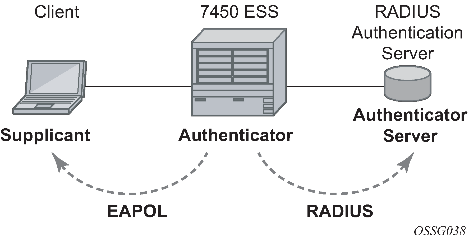
The authentication exchange is carried out between the supplicant and the authentication server, the authenticator acts only as a bridge. The communication between the supplicant and the authenticator is done through the Extended Authentication Protocol (EAP) over LANs (EAPOL). On the back end, the communication between the authenticator and the authentication server is done with the RADIUS protocol. The authenticator is therefore a RADIUS client, and the authentication server a RADIUS server.
The messages involved in the authentication procedure are shown in 802.1x authentication scenario. The router initiates the procedure when the Ethernet port becomes operationally up, by sending a special PDU called EAP-Request/ID to the client. The client can also initiate the exchange by sending an EAPOL-start PDU, if it does not receive the EAP-Request/ID frame during bootup. The client responds on the EAP-Request/ID with a EAP-Response/ID frame, containing its identity (typically username + password).
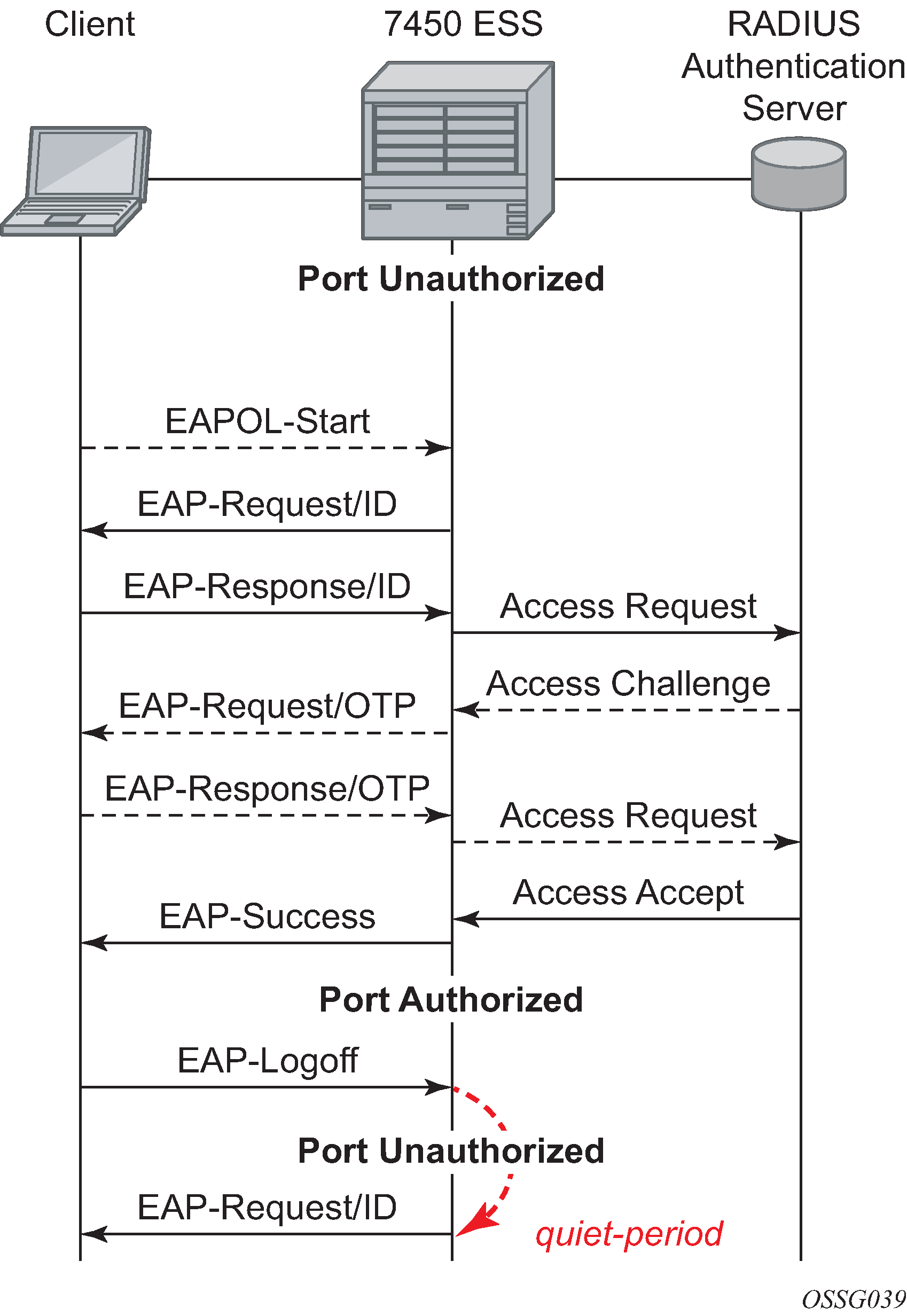
After receiving the EAP-Response/ID frame, the router encapsulates the identity information into a RADIUS AccessRequest packet, and sends it off to the configured RADIUS server.
The RADIUS server checks the supplied credentials, and if approved returns an Access Accept message to the router. The router notifies the client with an EAP-Success PDU and puts the port in authorized state.
802.1x timers
The 802.1x authentication procedure is controlled by a number of configurable timers and scalars. There are two separate sets, one for the EAPOL message exchange and one for the RADIUS message exchange. See 802.1x EAPOL timers (left) and RADIUS timers (right) for an example of the timers on the 7750 SR.

EAPOL timers:
transmit-period
This timer indicates how many seconds the Authenticator listens for an EAP-Response/ID frame. If the timer expires, a new EAP-Request/ID frame is sent and the timer restarted. The default value is 60. The range is 1 to 3600 seconds.
supplicant-timeout
This timer is started at the beginning of a new authentication procedure (transmission of first EAP-Request/ID frame). If the timer expires before an EAP-Response/ID frame is received, the 802.1x authentication session is considered as having failed. The default value is 30. The range is 1 to 300.
quiet-period
This timer indicates number of seconds between authentication sessions. It is started after logout, after sending an EAP-Failure message or after expiry of the supplicant-timeout timer. The default value is 60. The range is 1 to 3600.
RADIUS timer and scalar:
max-auth-req
This scalar indicates the maximum number of times that the router sends an authentication request to the RADIUS server before the procedure is considered as having failed. The default value is value 2. The range is 1 to 10.
server-timeout
This timer indicates how many seconds the authenticator waits for a RADIUS response message. If the timer expires, the access request message is sent again, up to max-auth-req times. The default value is 60. The range is 1 to 3600 seconds.
The router can also be configured to periodically trigger the authentication procedure automatically. This is controlled by the enable re-authentication and re-auth-period parameters. Reauth-period indicates the period in seconds (since the last time that the authorization state was confirmed) before a new authentication procedure is started. The range of reauth-period is 1 to 9000 seconds (the default is 3600 seconds, one hour). Note that the port stays in an authorized state during the re-authentication procedure.
802.1x tunneling
Tunneling of untagged 802.1x frames received on a port is supported for both Epipe and VPLS service using either null or default SAPs (for example 1/1/1:*) when the config>port>ethernet>dot1x port-control is set to force-auth.
When tunneling is enabled on a port (using the command configure port port-id ethernet dot1x tunneling), untagged 802.1x frames are treated like user frames and are switched into Epipe or VPLS services which have a corresponding null SAP or default SAP on that port. In the case of a default SAP, it is possible that other non-default SAPs are also present on the port. Untagged 802.1x frames received on other service types, or on network ports, are dropped.
When tunneling is required, it is expected that it is enabled on all ports into which 802.1x frames are to be received. The configuration of dot1x must be configured consistently across all ports in LAG as this is not enforced by the system.
Note that 802.1x frames are treated like user frames, that is, tunneled, by default when received on a spoke or mesh SDP.
Per-host authentication
Per-host authentication enables SR OS to authenticate each host individually and allows or disallows the PDUs from this host through the port. Per-host authentication is configurable using the CLI.
When dot1x tunneling is disabled, the port does not allow any PDUs to pass through, with the exception of dot1x packets, which are extracted.
When per-host-authentication is configured on the port for dot1x, each host is authenticated individually according to the RADIUS policy and host traffic is allowed or disallowed through the port. After the first successful host authentication, the behavior is the following:
On downstream (that is, traffic from the network to the host), the port is authorized and allows all traffic to go through.
On upstream (that is, traffic from the host to the network), the port is authorized, but allows only traffic from the authenticated hosts. When a host is allowed through the port, all of the PDUs for that host are allowed to pass through the port, including untagged or tagged packets. The traffic from any unauthenticated host is disallowed.
For per-host authentication, EAPOL packets are sent to the RADIUS server using the RADIUS protocol. The calling station identifier is the source MAC address of the host and is usually present in the packet. The identifier is used to allow or disallow the host source MAC address based on the RADIUS success or failure answer.
The hosts are authenticated periodically. If a host is authenticated and placed on the allow list and a subsequent authentication fails, that host is removed from the allow list.
If a host authenticates unsuccessfully multiple times, that host is put on a disallow list for a specific amount of time. That is, enabling per-host authentication provides per-host (source MAC) DoS mitigation.
Duplicate MAC addresses are not allowed on the port.
All logs display per-host authentication.
Per-host authentication interaction with dot1x
When per host authentication is first enabled, all MAC addresses on the port are denied. The user can allow MAC addresses using the static source MAC or dot1x host authentication. The following considerations apply when dot1x authentication is used.
If the 802.1x authentication mode is configured as force-auth (using the command config>port>ethernet>dot1x port-control), any host that sends EAPOL frames is authenticated without requiring any exchange with the RADIUS server.
If config>system>security dot1x is configured as shutdown, the port behavior is the same as in the force-auth case.
-
If the 802.1x authentication mode is configured as auto, the hosts are authenticated using RADIUS. However, if config>system>security dot1x is configured as shutdown, the force-auth behavior takes effect.
Static allow source MAC
A host can be added to the Allow MAC list statically, without being authenticated using dot1x. In this case, the host source MAC address must be added manually using the CLI.
If the same host is added to the list using dot1x and the CLI, the static configuration takes precedence. If the host is added using the CLI, the host is placed on the Allow list. If the same host tries to authenticate using RADIUS and the authentication fails, the host is still allowed through the port because it was statically added using the CLI command config>port>ethernet>dot1x>per-host-authentication>allowed-source-macs mac-address mac-address.
Tagged dot1x authentication
dot1x packets can arrive tagged or untagged on the authenticator port from the host. SR OS can be configured to tunnel or extract tagged dot1x packets. SR OS forwards tagged dot1x packets only.
The tunneling or extracting of tagged dot1x packets can be enabled for dot1q (tunnel-dot1q) and QinQ (tunnel-qinq) encapsulation types.
Each of the encapsulation types configured on the port can be configured to tunnel dot1x packets or extract dot1x packets to be authenticated using a configured RADIUS policy.
The extraction or tunneling of tagged packets applies to any tag value.
Dot1x and LAG
For dot1x authentication support, when the primary port member of the LAG is configured with dot1x, all members inherit the dot1x functionality. Dot1x packets can be extracted on any LAG member and sent to the RADIUS server for processing and authentication. After a successful authentication, the host is allowed on all LAG members. The host dot1x packets can be extracted on one LAG member, while the actual traffic traverses another LAG member. The following is the behavior of dot1x in a LAG bundle:
-
When port members are added to the LAG and dot1x is enabled, all ports inherit the same dot1x configuration as the primary port member of the LAG.
-
If a host source address (SA) is authenticated through one of the LAG member ports, all ports on the LAG bundle are authorized and pass traffic.
-
When a new port member is added to the LAG, if the LAG bundle has been authenticated and is authorized, the new port member is authorized as well.
-
Dot1x configuration changes are allowed on the primary LAG member only. A port can be added to a LAG only if its dot1x configuration aligns with that of the primary LAG member. If at least one LAG member is authorized, all LAG members are authorized.
In an upgrade scenario, when an older configuration file (admin save) is executed on a new release, a warning is displayed instead of an error for a command that violates the dot1x configuration change behavior; the violating command is ignored.
-
If a port is removed from the LAG bundle, the port becomes unauthorized and the EAP negotiation should authorize the port again. This is true for all ports in the LAG bundle, primary or not.
- When Random Early Discard (RED) updates are
received during an ISSU on a LAG member in standby, the
following updates are ignored:
- enable dot1x on a LAG member
- authorize a LAG member
When a port is added to a LAG during ISSU, its dot1x configuration is reset to the default values.
SR host authentication behaviour
SR allows the same MAC source address (MAC SA) on different ports if the MAC address is authenticated. Multiple hosts with the same MAC address can reside and get authenticated on different ports.
Authentication lists
The following authentication lists are supported:
authenticated host list
This list contains up to 1000 hosts. Only hosts that have been authenticated through RADIUS and are allowed through the port are included in this list.
-
unauthenticated host list
This list contains up to 2000 hosts. Only hosts that have failed authentication or are in the process of being authenticated are included in this list.
If this list reaches the 2000-host limit and a new host is being authenticated, the new host bumps off the list the first host that has failed authentication. The following sequence shows an example:
Unauthenticated list
Host 1 authenticating
Host 2 failed authentication
….
Host 2000 authenticating
Host 2001 just arrived, this host should bump Host 2 off in the list, not Host 1.
If all hosts are in authenticating state, the new Host 2001 is not allowed on the list.
802.1x configuration and limitations
Configuration of 802.1x network access control on the router consists of two parts:
generic parameters, which are configured under config>system>security>dot1x
port-specific parameters, which are configured under config>port>ethernet>dot1x
The following considerations apply:
- If per-host authentication is not configured, the authentication of any host on the port provides access to the port for any device, even if only a single client has been authenticated.
- 802.1x authentication can only be used to gain access to a pre-defined Service Access Point (SAP). It is not possible to dynamically select a service (such as a VPLS service) depending on the 802.1x authentication information.
- If 802.1x access control is enabled and a high rate of 802.1x frames are received on a port, that port is blocked for a period of 5 minutes as a DoS protection mechanism.
Disabling the 802.1x functionality on a port
By default, the 802.1x functionality consisting of packet extraction and processing on the CPM is enabled on each port.
Use the following commands to administratively disable the 802.1x functionality on a port by not extracting the dot1x packets to the CPM:
- configure>port>ethernet>dot1x shutdown (classic CLI)
- configure port ethernet dot1x admin-state (MD-CLI)
MACsec
Media Access Control Security (MACsec) is an industry-standard security technology that provides secure communication for almost all types of traffic on Ethernet links. MACsec provides point-to-point and point-to-multipoint security on Ethernet links between directly-connected nodes or nodes connected via a Layer 2 cloud. MACsec can identify and prevent most security threats, including:
denial of service
intrusion
man-in-the-middle
masquerading
passive wiretapping
playback attacks
MACsec Layer 2 encryption is standardized in IEEE 802.1AE. MACsec encrypts anything from the 802.1AE header to the end of the payload including 802.1Q. MACsec leaves the DMAC and SMAC in clear text.
802.1 AE LAN-MODE shows the 802.1AE LAN-Mode structure.
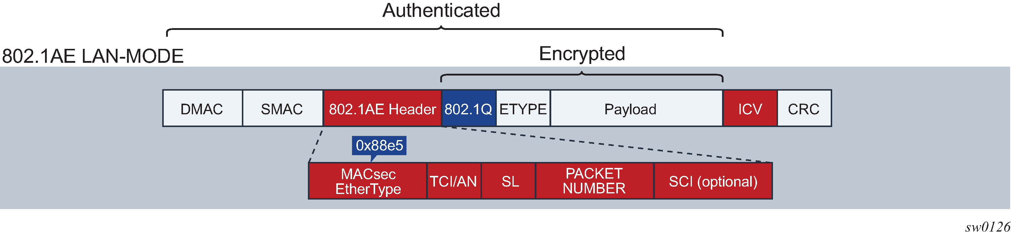
The forwarding on a MACsec packet is performed using the destination MAC address, which is in clear text.
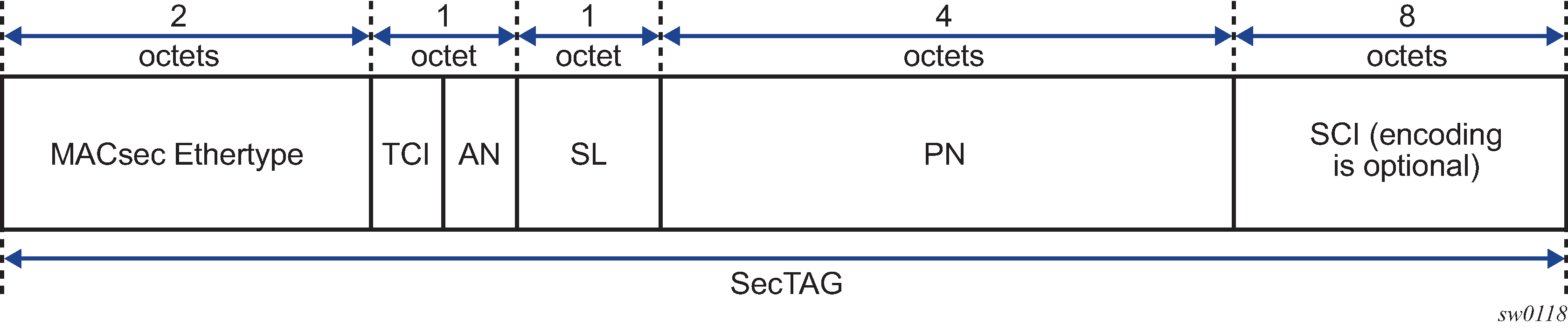
MACsec 802.1AE header (SecTAG)
The MACsec 802.1AE header includes a security TAG (SecTAG) field that contains the following:
association number within the channel
packet number to provide a unique initialization vector for encryption and authentication algorithms as well as protection against replay attack
optional LAN-Wide secure channel identifier
The security field, which is identified by the MACsec Ethertype, conveys the following information:
TAG Control Information (TCI)
Association Number (AN)
Short Length (SL)
Packet Number (PN)
Optionally-encoded Secure Channel Identifier (SCI)
SecTAG format shows the format of the SecTAG.
MACsec encryption mode
There are two main modes of encryption in MACsec:
VLAN in clear text (WAN Mode)
VLAN encrypted
802.1AE dictates that the 802.1Q VLAN needs to be encrypted. Some vendors give the option of configuring the MACsec on a port with VLAN in clear text.
SR OS supports both modes. On the 7750 SR and 7450 ESS, 1/10 Gig cards support both mode of operation.
802.1 AE LAN and WAN modes and VLAN encrypted/clear shows the VLAN encrypted and VLAN in clear.

MACsec encryption per traffic flow encapsulation matching
In Release 16.0 and later, MACsec can be applied to a selected sub-set of the port traffic, based on the type and value of the packet encapsulation. The SR OS can be configured to match and encrypt the following traffic encapsulation types:
all encap traffic arriving on port including untagged, single-tag, and double-tag. This is the default behavior of MACsec and the only option supported in releases before 16.0.
untagged only traffic.
single-tag or dot1q traffic. In this mode, MACsec can apply to a specific tag or wild card tag where all single-tag traffic is matched.
double-tag or QinQ traffic. In this mode, MACsec can apply to a specific service tag, a specific service and customer tag, or a wild card for any QinQ traffic.
MKA PDUs are generated specifically for the traffic encapsulation type that is being matched.
MACsec key management modes
There are four main, key management modes in MACsec. MACsec key management modes describes these management modes.
| Keying | Explanation | SR OS support | Where used |
|---|---|---|---|
Static SAK |
Manually configures each node with a static SAK, SAM, or CLI |
Switch to switch |
|
Static CAK PRE SHARED KEY |
Uses a dynamic MACsec Key Management (MKA) and uses a configured pre shared key to drive the CAK. The CAK encrypts the SAK between two peers and authenticates the peers |
✓ |
Switch to switch |
Dynamic CAK EAP Authentication |
Uses a dynamic MKA and an EAP Master System Key (MSK) to drive the CAK. The CAK encrypts the SAK between two peers and authenticates the peers |
Switch to switch |
|
Dynamic CAK MSK distribution via RADIUS and EAP-TLS |
Stores the MSKs in the Radius server and distributes to the hosts via EAP-TLS. This is typically used in the access networks where a large number of hosts use MACsec and connect to an access switch. MKA uses MSK to drive the CAK. The CAK encrypts the SAK between 2 peers and authenticates the peers |
Host to switch |
MACsec terminology
MACsec concepts for static-CAK illustrates some of the main concepts used in MACsec for the static-CAK scenario.
MACsec terms describes the MACsec terminology.
| MACsec term | Description |
|---|---|
CA: Connectivity Association |
A security relationship, established and maintained by key agreement protocols (MKA), that comprises a fully-connected subset of the service access points in stations attached to a single LAN that are to be supported by MACsec. |
MKA: MACsec Key Agreement Protocol |
Control protocol between MACsec peers, which is used for peer aliveness and encryption key distribution. MACsec Key Agreement is responsible for discovering, authenticating, and authorizing the potential participants in a CA. |
SecY: MAC Security Entity |
Operates the MAC Security protocol within a system. Manages and identifies the SC and the corresponding active SA. |
SC: Security Channel |
SC provides a unidirectional point-to-point or point-to-multipoint communication. Each SC contains a succession of SAs and each SC has a different SAK. |
SA: Security Association |
In the cases of SR OS 2 SA per SC, each with a different SAK, each SC comprises a succession of SAs. Each SA is identified by the SC identifier, concatenated with a two-bit association number. The Secure Association Identifier (SAI), therefore created, allows the receiving SecY to identify the SA, and therefore the SAK used to decrypt and authenticate the received frame. The AN, and therefore the SAI, is only unique for the SAs that can be used or recorded by participating SecYs at any instant. MACsec Key Agreement is responsible for creating and distributing SAKs to each of the SecYs in a CA. This key creation and distribution is independent of the cryptographic operation of each of the SecYs. The decision to replace one SA with its successor is made by the SecY that transmits using the SC, after MACsec Key Agreement has informed it that all the other SecYs are prepared to receive using that SA. No notification, other than receipt of a secured frame with a different SAI is sent to the receiver. A SecY must always be capable of storing SAKs for two SAs for each inbound SC, and of swapping from one SA to another without notice. Certain LAN technologies can reorder frames of different priority, so reception of frames on a single SC can use interleaved SA. |
SAK: Security Association Key |
SAK is the encryption key used to encrypt the datapath of MACsec. |
MACsec static CAK
MACsec uses SAs for encryption of packets. SA is a security relationship that provides security guarantees for frames transmitted from one member of a CA to the others. Each SA contains a single secret key (SAK) where the cryptographic operations used to encrypt the datapath PDUs.
SAK is the secret key used by an SA to encrypt the channel.
When enabled, MACsec uses a static CAK security mode. Two security keys, a connectivity association key (CAK) that secures control plane traffic and a randomly-generated secure association key (SAK) that secures data plane traffic are used to secure the point-to-point or point-to-multipoint Ethernet link. Both keys are regularly exchanged between both devices on each end of the Ethernet link to ensure link security.
MACsec generating the CAK illustrates MACsec generating the CAK.

The node initially needs to secure the control plane communication to distribute the SAKs between two or more members of a CA domain.
The securing of control plane is done via CAK. To generate the CAK, there are two main methods:
EAPoL (SR OS does not support EAPoL)
pre shared key (CAK and CKN values are configured manually via CLI). The following CAK and CKN rules apply.
CAK is a 32 hexadecimal characters for 128-bit key and 64 hexadecimal characters for 256-bit key depending on which algorithm is used for control plane encryption (for example, aes-128-cmac or aes-256-cmac).
CKN is a 32 octets char (64 hex) and it is the connectivity association key name which identifies the CAK. This allows each of the MKA participants to select which CAK to use to process a received MKPDU. MKA places no restriction on the format of the CKN, except that it must comprise an integral number of octets, between 1 and 32 (inclusive), and that all potential members of the CA use the same CKN.
CKN and CAK must match on peers to create a MACsec Secure CA.
MACsec control plane and encryption illustrates the MACsec control plane authentication and encryption.

After the CAK is generated, it can obtain two other keys. These keys are:
- Key Encryption Key (KEK)
- used to wrap and encrypt the SAKs
- Integrity Connection Value (ICV) Key (ICK)
- used for an integrity check of each MKPDU sent between two CAs
The key server then creates a SAK, that is shared with the CAs of the security domain, and that SAK secures all data traffic traversing the link. The key server continues to periodically create and share a randomly-created SAK over the point-to-point link for as long as MACsec is enabled.
The SAK is encrypted via the AES-CMAC, the KEK as encryption key, and ICK as integration key.
SAK rollover
SR OS regenerates the SAK after the following events:
when a new host has joined the CA domain and MKA hellos are received from this host
when the sliding window is reaching the end of its 32-bit or 64-bit length
when a new PSK is configured and a rollover of PSK has been executed
MKA
Each MACsec peer operates the MACsec Key Agreement Protocol (MKA). Each node can operate multiple MKAs based on the number of CA to which the node belongs. Each MKA instance is protected by a distinct secure connectivity Association key (CAK), that allows each PAE to ensure that information for a specific MKA instance is only accepted from other peer that also possess that CAK, and therefore identifying the peers as members or potential members of the same CA. See MACsec static CAK for information about the CAK identification process done via CKN.
MKA PDU generation
MKA PDU generation describes the MKA PDUs generated for different traffic encapsulation matches.
| Configuration | Configuration example (<s-tag>.<c-tag>) | MKA packet generation | Traffic pattern match/behavior |
|---|---|---|---|
All-encap |
config>port>ethernet> dot1x>macsec sub-port 10 encap-match all-encap ca-name 10 |
untagged MKA packet |
Matches all traffic on port, including untagged, single-tag, and double-tag. Default behavior; only available behavior in releases before 16.0. |
UN-TAG |
config>port>ethernet> dot1x>macsec sub-port 1 encap-match untagged ca-name 2 |
untagged MKA packet |
Matches only untagged traffic on port |
802.1Q single S-TAG (specific S-TAG) |
config>port>ethernet> dot1x>macsec sub-port 2 encap-match dot1q 1 ca-name 3 |
MKA packet generated with S-TAG=1 |
Matches only single-tag traffic on port with tagID of 1 |
802.1Q single S-TAG (any S-TAG) |
config>port>ethernet> dot1x>macsec sub-port 3 encap-match dot1q * ca-name 4 |
untagged MKA packet |
Matches any dot1q single-tag traffic on port |
802.1ad double tag (both tag have specific TAGs) |
config>port>ethernet> dot1x>macsec sub-port 4 encap-match qinq 1.1 ca-name 5 |
MKA packet generated with S-tag=1 and C-TAG=1 |
Matches only double-tag traffic on port with service tag of 1 and customer tag of 1 |
802.1ad double tag (specific S-TAG, any C-TAG) |
config>port>ethernet> dot1x>macsec sub-port 6 encap-match qinq 1.* ca-name 7 |
MKA packet generated with S-TAG=1 |
Matches only double-tag traffic on port with service tag of 1 and customer tag of any |
802.1ad double tag (any S-TAG, any C-TAG) |
config>port>ethernet> dot1x>macsec sub-port 7 encap-match qinq *.* ca-name 8 |
untagged MKA packet |
Matches any double-tag traffic on port |
Tags in clear behavior by traffic encapsulation types
Tags in clear behavior describes how single or double tags in clear configuration under a connectivity association affects different traffic flow encryptions.
By default all tags are encrypted in CA. An MKA can be generated without any tags (un-tag) but the data being matched can be based on dot1q or QinQ.
| Configuration | Traffic pattern match/behavior | Sub-port's CA configuration: no tag in clear text | Sub-port's CA configuration: single-tag in clear text | Sub-port's CA configuration: double tag in clear text |
|---|---|---|---|---|
PORT All-encap |
Matches all traffic on port, including untagged, single-tag, double-tag (Release 15.0 default behavior) |
MKA PDU: untagged Untagged traffic: encrypted Single-tag traffic: encrypted, no tag in clear Double-tag traffic: encrypted, no tag in clear |
MKA PDU: untagged Untagged traffic: in clear Single-tag traffic: encrypted, single-tag in clear Double-tag traffic: encrypted, single-tag in clear |
MKA PDU: untagged Untagged traffic: in clear Single-tag traffic: in clear Double-tag traffic: encrypted, double-tag in clear |
untagged |
Matches only untagged traffic on port |
MKA PDU: untagged Untagged traffic: encrypted Single-tag traffic: not matched by this MACsec policy Double-tag traffic: not matched by this MACsec policy |
N/A |
N/A |
802.1Q single tag (specific tag) |
Matches only single-tag traffic on port with the configured tag value |
MKA PDU: untagged Untagged traffic: not matched by this MACsec policy Single-tag traffic: tag is encrypted Double-tag traffic: not matched by this MACsec policy |
MKA PDU: same tag as the one configured under encap-match Untagged traffic: not matched by this MACsec policy Single-tag traffic: tag is in clear Double-tag traffic: not matched by this MACsec policy |
N/A |
802.1Q single tag (any tag) |
Matches all single-tag traffic on port |
MKA PDU: untagged Untagged traffic: not matched by this MACsec policy Single-tag traffic: encrypted Double-tag traffic: not matched by this MACsec policy |
MKA PDU: untagged Untagged traffic: not matched by this MACsec policy Single-tag traffic: encrypted with single tag in clear Double-tag traffic: not matched by this MACsec policy |
N/A |
802.1ad double tag (both tag have specific values) |
Matches only double-tag traffic on port with both configured tag values |
MKA PDU: untagged Untagged traffic: not matched by this MACsec policy Single-tag traffic: not matched by this MACsec policy Double-tag traffic matching both configured tags: encrypted, no tag in clear |
MKA PDU: single tag, equal to S-TAG Untagged traffic: not matched by this MACsec policy Single-tag traffic: not matched by this MACsec policy Double-tag traffic matching both configured tags: single S-TAG in clear |
MKA PDU: double tag, equal to the values configured under the encap-match Untagged traffic: not matched by this MACsec policy Single-tag traffic: not matched by this MACsec policy Double-tag traffic matching both configured tags: encrypted, both tags in clear |
802.1ad double tag (specific S-TAG, any C-TAG) |
Matches only double-tag traffic on port with the configured S-TAG |
MKA PDU: untagged Untagged traffic: not matched by this MACsec policy Single-tag traffic: not matched by this MACsec policy Double-tag traffic matching the configured S-TAG: encrypted, no tag in clear |
MKA PDU: single tag, equal to S-TAG Untagged traffic: not matched by this MACsec policy Single-tag traffic: not matched by this MACsec policy Double-tag traffic matching the configured S-TAG: S-TAG tag in clear |
MKA PDU: single tag, equal to S-TAG Untagged traffic: not matched by this MACsec policy Single-tag traffic: not matched by this MACsec policy Double-tag traffic matching the configured S-TAG: both tags in clear |
802.1ad double tag (any S-TAG, any C-TAG |
Matches all double-tag traffic on port |
MKA PDU: untagged Untagged traffic: not matched by this MACsec policy Single-tag traffic: not matched by this MACsec policy Double-tag traffic: encrypted, no tag in clear |
MKA PDU: untagged Untagged traffic: not matched by this MACsec policy Single-tag traffic: not matched by this MACsec policy Double-tag traffic: S-TAG tag in clear |
MKA PDU: untagged Untagged traffic: not matched by this MACsec policy Single-tag traffic: not matched by this MACsec policy Double-tag traffic: both tags in clear |
Pre-shared key
A peer may support the use of one or more pre-shared keys (PSKs). An instance of MKA operates for each PSK that is administratively configured as active.
A pre-shared key may be created by NSP, or entered in CLI manually.
Each PSK is configured with two fields. The two fields are:
CKN (connectivity association name)
CAK value
The CAK name (CKN) is required to be unique per port among the configured sub-ports, and can be used to identify the key in subsequent management operations.
Each static CAK configuration can have two pre-shared key entries for rollover. The active PSK index dictates the CAK that is used for encrypting the MKA PDUs.
NSP has additional functionality to roll over and configure the PSK. The rollover via NSP can be based on a configured timer.
MKA Hello timer
MKA uses a member identifier (MI) to identify each node in the CA domain.
A participant proves liveness to each of its peers by including their MI, together with an acceptably-recent message number (MN), in an MKPDU.
To avoid a new participant having to respond to each MKPDU from each partner as it is received, or trying to delay its reply until it is likely that MI MN tuples have been received from all potential partners, each participant maintains and advertises both of the following:
live peers list
This list includes all the peers that have included the participant's MI and a recent MN in a recent MKPDU.
potential peers list
This list includes all the other peers that have transmitted an MKPDU that has been directly received by the participant or that were included in the Live Peers List of a MKPDU transmitted by a peer that has proved liveness.
Peers are removed from each list when an interval of between MKA Life Time and MKA Life Time plus MKA Hello Time has elapsed since the participant's recent MN was transmitted. This time is sufficient to ensure that two or more MKPDUs are lost or delayed before the incorrect removal of a live peer.
MKA participant timer values describes the MKA participant timer values used on SR OS.
| Timer use | Timeout (parameter) | Timeout (parameter) |
|---|---|---|
Per participant periodic transmission, initialized on each transmission on expiry |
MKA Hello Time or MKA Bounded Hello Time |
2.0 0.5 |
Per peer lifetime, initialized when adding to or refreshing the Potential Peers List or Live Peers List, expiry causes removal from the list |
MKA Life Time |
6.0 |
Participant lifetime, initialized when participant created or following receipt of an MKPDU, expiry causes participant to be deleted |
||
Delay after last distributing a SAK, before the Key Server distributes a fresh SAK following a change in the Live Peer List while the Potential Peer List is still not empty |
MACsec Capability, Desire, and encryption offset
802.1x-2010 had identified two fields in the MKA PDU. Those fields are:
MACsec Capability
Desire
MACsec Capability signals weather MACsec is capable of integrity and confidentiality. MACsec basic settings describes the four basic settings for MACsec Capability.
| Setting | Description |
|---|---|
0 |
MACsec is not implemented |
1 |
Integrity without confidentiality |
2 |
The following are supported:
|
| 31 | The following are supported:
|
An encryption offset of 0, 30, or 50 starts from the byte after the SecTAG (802.1ae header). Ideally, the encryption offset should be configured for IPv4 (offset 30) and IPv6 (offset 50) to leave the IP header in the clear text. This allows routers and switches to use the IP header for LAG or ECMP hashing.
Key server
The participants, in an MKA instance agree on a Key Server, are responsible for the following:
deciding on the use of MACsec
cipher suite selection
SAK generation and distribution
SA assignment
identifying the CA when two or more CAs merge
Each participant in an MKA instance uses the Key Server priority (an 8-bit integer) encoded in each MKPDU to agree on the Key Server. Each participant selects the live participant advertising the highest priority as its Key Server whenever the Live Peers List changes, provided that highest priority participant has not selected another as its Key Server or is unwilling to act as the Key Server. If a Key Server cannot be selected, SAKs are not distributed. In the event of a tie for highest priority Key Server, the member with the highest priority SCI is chosen. For consistency with other uses of the SCI's MAC address component as a priority, numerically lower values of the Key Server Priority and SCI are accorded the highest priority.
SA limits and network design
Each MACsec device supports 64 TX-SAs and 64 RX-SAs. An SA (Security Association) is the key to encrypt or decrypt the data.
In accordance with the IEEE 802.1AE standard, each SecY contains a SC. An SC is a unidirectional concept; for example, Rx-SC or Tx-SC. Each SC contains at least one SA for encryption on Tx-SC and decryption on Rx-SC. Also, for extra security, each SC should be able to roll over the SA. Nokia recommends that each SC should have two SAs for rollover purposes.
Each MACsec phy, referred to as a MACsec security zone, supports 64Tx-SAs and 64 RX-SAs. Assuming two SAs per SC for SA rollover, then each security zone supports 32 RX-SC and 32 TX-SC.
Port mapping to security zone describes the port mapping to security zones.
| MDA | Ports in security zone 1 | Ports in security zone 2 | Ports in security zone 3 | SA limit per security zone |
|---|---|---|---|---|
12-port SFP+/SFP MDA-e |
Ports 1, 2, 3, 4 |
Ports 5, 6, 7, 8 |
Ports 9, 10, 11, 12 |
Rx-SA = 64 Tx-SA = 64 |
P2P (switch to switch) topology
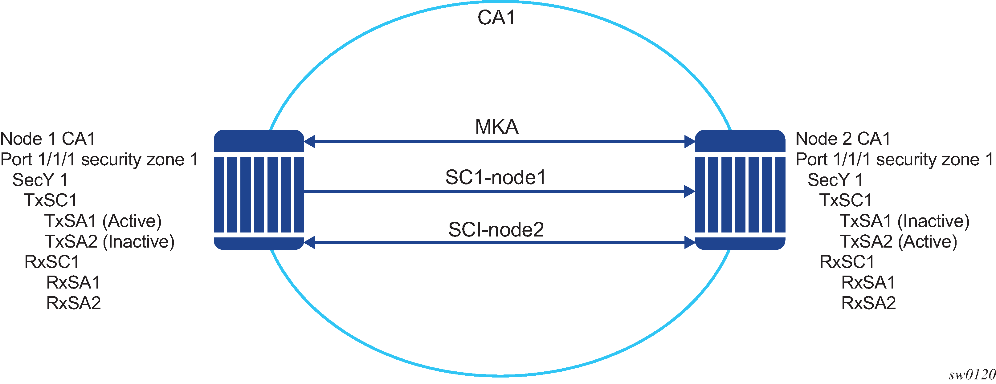
In a point-to-point topology, each router needs a single security zone and single Tx-SC for encryption and a single Rx-SC for decryption. Each SC has two SAs. In total for point-to-point topology, four SAs are needed, two RxSA for RxSC1 and two TXSA for TxSC1. See Switch point to switch point topology.
P2MP (switch to switch) topology
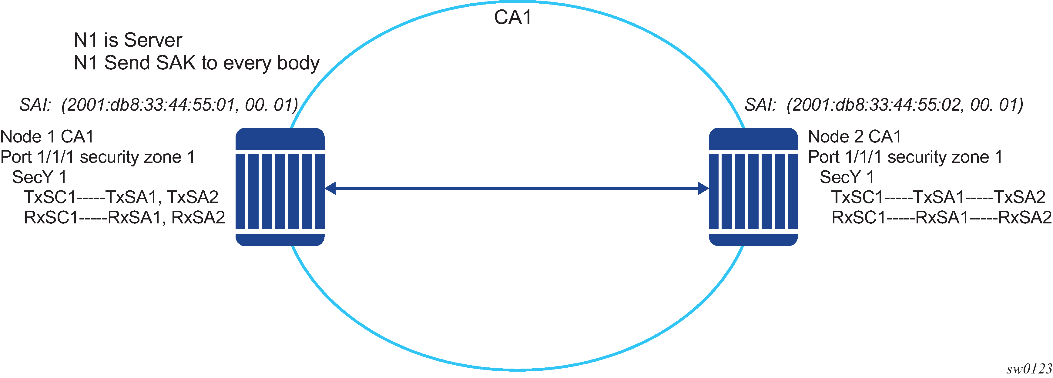
In a multipoint topology with N nodes, each node needs a single TxSC and N RxSC, one for each one of the peers. As such, 64 max RX-SA per security zone translates to 32 Rx-SCs, which breaks down to only 32 peers (for example, only 33 nodes in the multipoint topology per security zone, from each node perspective there is one TxSC and 32 RxSC).
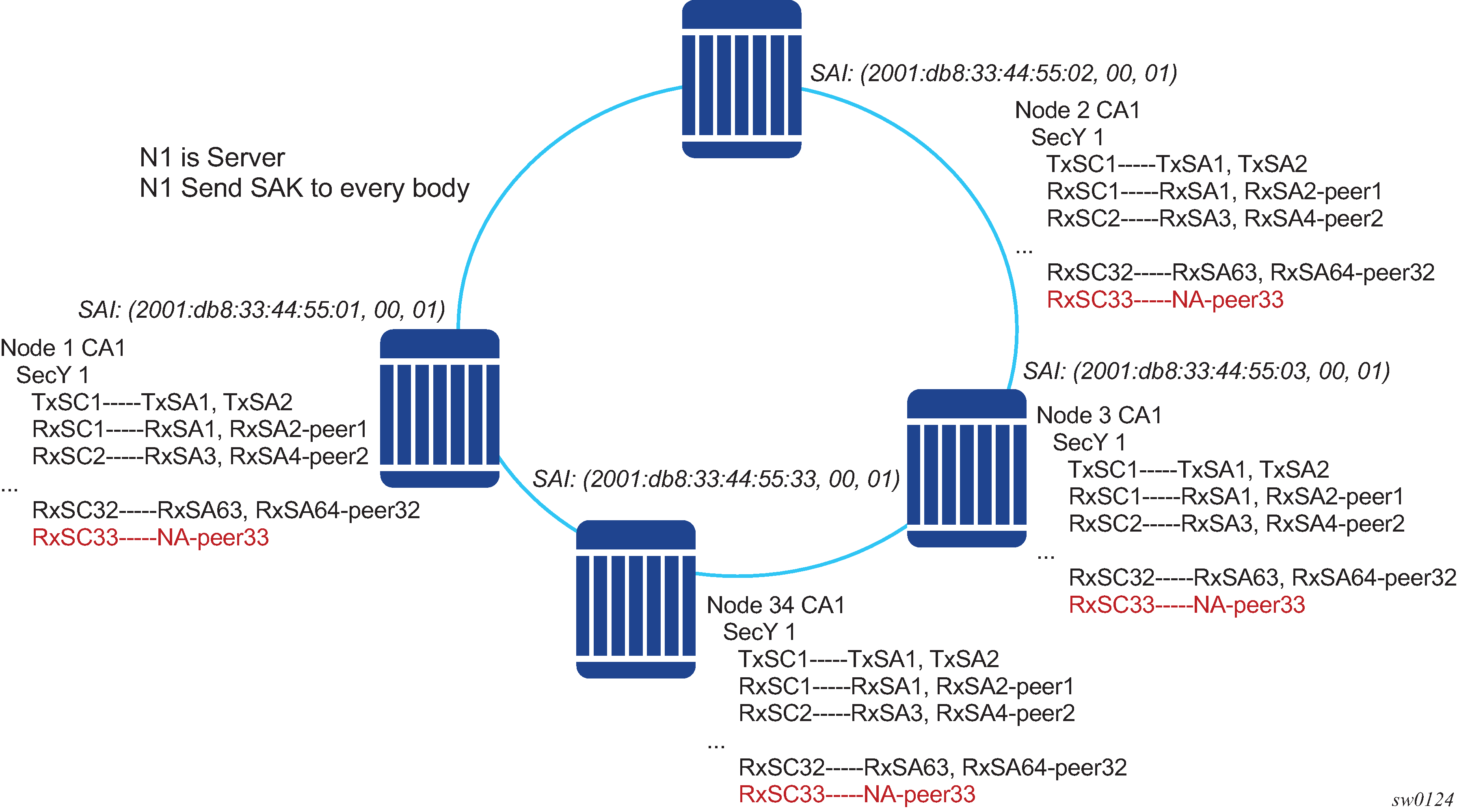
In Switch multi-point to switch multi-point topology, when the 34rd node joins the multi-point topology, all other 33 nodes that are already part of this domain do not have any SAs to create an RxSC for this 34th node. However, the 34th node has a TxSC and accepts 32 peers. The 34th node starts to transmit and encrypt the PDUs based on its TxSC. However, because all other nodes do not have a SC for this SAI, they drop all Rx PDUs.
It is recommended to ensure that a multicast domain, for a single security zone, does not exceed 32 peers or the summation of all the nodes, in a security zone's CA domain, do not exceed 33. This is the same is if a security zone has four CAs, the summation of all nodes in the four CAs should be 33 or less.
SA exhaustion behavior
In SA limits and network design, it was described that a security zone has 64 RxSAs and 64 TxSAs. Two RxSAs are used for each RxSC for rollover purposes and two TxSAs are used for TxSC for rollover purposes. This translates to 32 peers per security zone.
Under each port, a max-peer parameter can be configured. This parameter assigns the number of peers allowed on that port.
Clear tag mode
In most Layer 2 networks, MAC forwarding is done via destination MAC address. The 802.1AE standard dictates that any field after source and destination MAC address and after the SecTAG is required to be encrypted. This includes the 802.1Q tags. In some VLAN switching networks, it may be needed to leave the 802.1Q tag in clear text.
SR OS supports the configuration of 802.1Q tag, in clear text, by placing the 802.1Q tag before the SecTAG or encrypted, by placing it after the SecTAG.
MACsec encryption of 802.1Q tags with clear-tag configured lists the MACsec encryption of 802.1Q tags when the clear-tag is configured on SR OS.
| Unencrypted format | Clear-tag-mode configuration | Pre-encryption (Tx) | Pre-decryption (Rx) |
|---|---|---|---|
Single tag (dot1q) |
Single-tag |
DA, SA, TPID, VID, Etype |
DA, SA, TPID, VID, SecTAG |
Single tag (dot1q) |
Double-tag |
DA, SA, TPID, VID, Etype |
DA, SA, TPID, VID, SecTAG |
Double tag (q-in-q) |
Single-tag |
DA, SA, TPID1, VID1, IPID2, VID2, Etype |
DA, SA, TPID1, VID1, SecTAG |
Double tag (q-in-q) |
Double-tag |
DA, SA, TPID1, VID1, IPID2, VID2, Etype |
DA, SA, TPID1, VID1, IPID2, VID2, SecTAG |
802.1X tunneling and multihop MACsec
MACsec is an Ethernet packet and, as with any other Ethernet packet, can be forwarded through multiple switches via Layer 2 forwarding. The encryption and decryption of the packets is performed via the 802.1x (MKA) capable ports.
To ensure that MKA is not terminated on any intermediate switch or router, the user can enable 802.1x tunneling on the corresponding port.
An example check to see if tunneling is enabled, is provided below.
*A:SwSim28>config>port>ethernet>dot1x# info
----------------------------------------------
      tunneling
By enabling tunneling, the 802.1X MKA packets transit the port, without being terminated, therefore MKA negotiation does not occur on a port that has 802.1X tunneling enabled.
EAPoL destination address
The MKA packets are transported over EAPoL with a multicast destination MAC address. At some point, it may be needed to have the MKA have a point-to-point connection to a peer node over a Layer 2 multihop cloud. In this case, the EAPoL destination MAC address can be set to the peer MAC address. This forces the MKA to traverse multiple nodes and establish an MKA session with the specific peer.
Mirroring consideration
Mirroring is performed before the MACsec encryption engine. Therefore, if a port is MACsec-enabled and also, that port is mirrored, all the mirrored packets are in cleartext.
SONET/SDH port attributes
One OC-3/STM-1 ports are supported on the TDM satellite. The ports can be configured for either SONET or SDH operation. SONET ports are configured for channelized OC-3 operation. SDH ports can be configured for channelized STM-1 operation.
The port’s transmit clock rate can be node or loop timed. The port’s receive clock rate can be used as a synchronization source for the system. The Section Trace (C1) byte can be configured by the user to ensure correct physical cabling. The port can activate and deactivate local line and internal loopbacks.
All SONET/SDH line alarms are configurable to be either enabled (default) or disabled. Link hold timers can be configured in 100ms increments to control link up and link down indications. The line signal degradation bit error rate (ber-sd) threshold and the line signal failure bit error rate (ber-sf) threshold can be configured.
The TDM satellite support all standard SR OC-3/STM-1 SFP optics including multi-mode, intermediate reach, and long reach. Single fiber mode is not supported.
When an Ethernet port is configured in WAN mode (xgig wan), you can change specific SONET/SDH parameters to reflect the SONET/SDH requirements for this port.
SONET/SDH path attributes
Any CES path can only be configured to operate in access mode. Each path has a configurable text description. The SONET/SDH signal label byte (C2) is configurable. The SONET/SDH path trace string (J1) is configurable. Payload scrambling cannot be enabled on CES paths. The valid SONET and SDH path configurations are shown in Valid SONET and SDH path configurations.
| Framing | Path configuration options per physical port | Max number of paths per TDM satellite port |
|---|---|---|
|
SDH |
STM1>AUG1>VC4>TUG3>TUG2>VC12>E1 STM1>AUG1>VC3>TUG2>VC12>E1 |
63 E1 |
|
SONET |
OC3>STS1 SPE>VT GROUP>VT1.5 SPE>DS1 |
84 DS1 |
|
SDH |
STM1>AUG1>VC4>TUG3>TUG2>TU11>VC11>DS1 STM1>AUG1>VC3>TUG2>VC11>DS1 |
84 DS1 |
All SONET/SDH path alarms are configurable to be either enabled (the default) or disabled. The MTU size is configurable per path in the range of 512 to 2092. The path uses a default MTU size set to equal the largest possible CES packet size.
Load balancing options are not applicable to channelized CES paths.
When an Ethernet port is configured in WAN mode (xgig wan), you can change specific SONET/SDH parameters to reflect the SONET/SDH requirements for this port.
APS
APS is designed to protect SONET/SDH equipment from linear unidirectional or bidirectional failures. The Network Elements (NEs) in a SONET/SDH network constantly monitor the health of the network. When a failure is detected, the network proceeds through a coordinated pre-defined sequence of steps to transfer (or switchover) live traffic to the backup facility (protection facility). This happens very quickly to minimize lost traffic. Traffic remains on the protection facility until the primary facility (working facility) fault is cleared, at which time the traffic may optionally be reverted to the working facility. An example is shown in APS protection (single chassis APS) and switchover.

Note that ‟facility” in the router’s context refers to the physical line (including intermediate transport/switching equipment) and directly attached line terminating hardware (SFP module, MDA and IOM). ‟Circuit” is also a term used for a link/facility (working-circuit).
A 1+1 APS group contains two circuits.
APS is configured on a port by port basis. If all ports on an MDA or IOM need to be protected then each port on the MDA or IOM must be individually added into an APS group.
Working and protection circuits can be connected to a variety of types of network elements (ADMs, DACSes, ATM switches, routers) and serve as an access or network port providing one or more services or network interfaces to the router. APS-protected SONET/SDH ports may be further channelized. The ports may be one of a variety of encapsulation types as supported by the MDA including PPP, FR and more. For information about MDAs, port types, switching modes, bundles and encapsulations supported with APS, see APS applicability, restrictions, and interactions.
Single chassis and multi-chassis APS
APS can operate in a single chassis configuration (SC-APS) or in a multi-chassis configuration (MC-APS).
An SC-APS group can span multiple ports, MDAs or IOMs within a single node whereas as MC-APS can span two separate nodes as shown in SC-APS versus MC-APS protection.
| Single chassis APS | Multi-chassis APS | |
|---|---|---|
Short form name |
SC-APS |
MC-APS |
Link failure protection (including intermediate transmission equipment failure) |
Yes |
Yes |
Optical/electrical module (SPF, XFP) failure protection |
Yes |
Yes |
MDA failure protection |
Yes |
Yes |
IOM failure protection |
Yes |
Yes |
Node failure protection |
No |
Yes |
The support of SC-APS and MC-APS depends on switching modes, MDAs, port types and encaps. For a definitive description of the MDAs, port types, switching modes, bundles and encapsulations supported with APS, see APS applicability, restrictions, and interactions.
APS on a single node (SC-APS)
In a single chassis APS both circuits of an APS group are terminated on the same node.
The working and protect lines of a single chassis APS group can be:
Two ports on the same MDA
Two ports on different MDAs but on the same IOM
Two ports on different MDAs on two different IOMs (installed in different slots)
Two ports on two TDM satellites
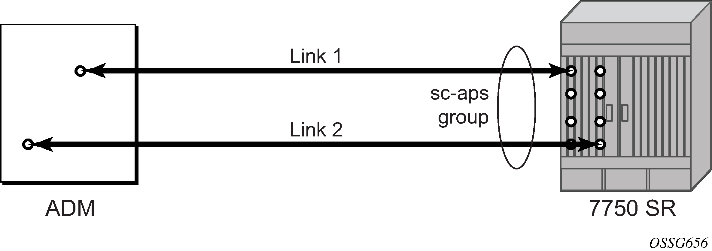
If the working and protection circuits are on the same MDA, protection is limited to the physical port and the media connecting the two devices. If the working and protection circuits are on different IOMs then protection extends to MDA or IOM failure. SC-APS group with MDA and IOM protection shows a configuration that provides protection against circuit, port, MDA, or IOM failure on the 7750 SR connected to an Add-Drop-Multiplexer (ADM).
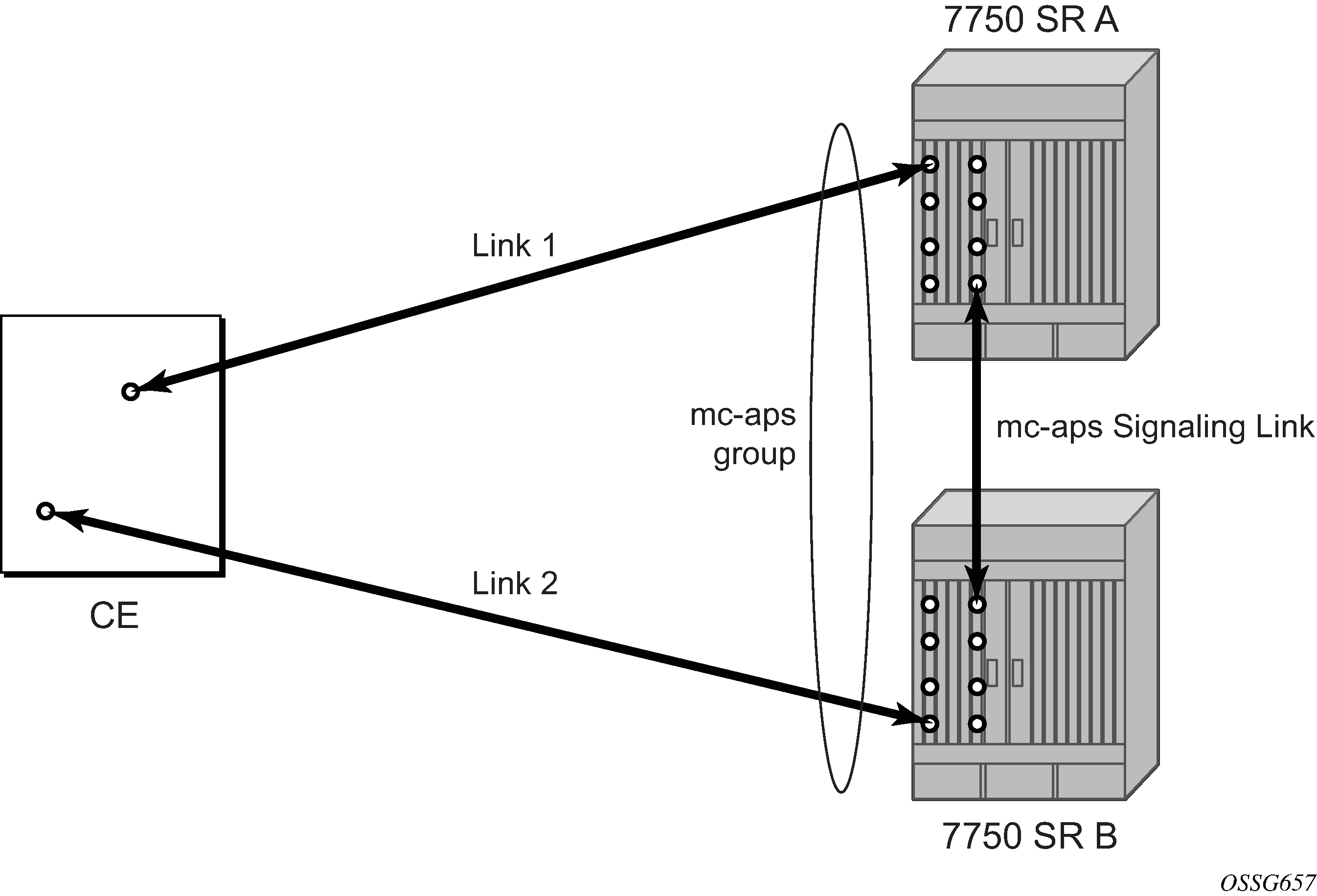
APS across two nodes (MC-APS)
Multi-Chassis APS functionality extends the protection offered by SC-APS to include protection against nodal (7750 SR) failure by configuring the working circuit of an APS group on one 7750 SR node while configuring the protect circuit of the same APS group on a different 7750 SR node.
These two nodes connect to each other with an IP link to establish an MC-APS signaling path between the two 7750 SRs. Note that the working circuit and the protect circuit must have compatible configurations (such as the same speed, framing, and port-type). The relevant APS groups in both the working and protection routers must have same group ID, but they can have different names (for example, group port descriptions). Although the working and protection routers can be different platforms (7750 SR-7 and a 7750 SR-c12), switchover performance may be impacted so it is recommended to avoid a mix of platforms in the same MC-APS group where possible. The configuration consistency between the working circuit/router and the protection circuit/router is not enforced by the 7750 SR. Service or network-specific configuration data is not signaled nor synchronized between the two service routers.
Signaling is provided using the direct connection between the two service routers. A heartbeat protocol can be used to add robustness to the interaction between the two routers. Signaling functionality includes support for:
APS group matches between service routers.
Verification that one side is configured as a working circuit and the other side is configured as the protect circuit. In case of a mismatch, a trap (incompatible neighbor) is generated.
Change in working circuit status is sent from the working router to keep the protect router in sync.
Protect router, based on K1/K2 byte data, member circuit status, and external request, selects the active circuit, and informs the working router to activate or de-activate the working circuit.
Note that external requests like lockout, force, and manual switches are allowed only on the APS group having the protection circuit.
The MC-APS group protects against node failure shows a Multi-Chassis APS group being used to protect against link, port, MDA, IOM or node failure.
APS switching modes
APS behavior and operation differs based on the switching mode configured for the APS group as shown in APS switching modes. Several switching modes are supported in the router.
The switching mode affects how the two directions of a link behave during failure scenarios and how APS tx operates.
Unidirectional / Bidirectional configuration must be the same at both sides of the APS group. The APS protocol (K byte messages) exchange switching mode information to ensure that both nodes can detect a configuration mismatch.
If one end of an APS group is configured in a Unidirectional mode (Uni 1+1 Sig APS or Uni 1+1 Sig+Data APS) then the other end must also be configured in a Unidirectional mode (Uni 1+1 Sig+Data APS).
If one end of an APS group is configured in a Bidirectional mode then the other end must also be configured in Bidirectional mode.
Table 12. APS switching modes Bidirectional 1+1 signaling APS Unidirectional 1+1 signaling APS Unidirectional 1+1 signaling and datapath APS Short form name
Bidir 1+1 Sig APS
Uni 1+1 Sig APS
Uni 1+1 Sig+Data APS
CLI
bidirectional
unidirectional
uni-1plus1
Interworks with a standards compliant APS implementation
Yes
Yes
Yes
Full 1+1 APS standards-based signaling
Yes
Yes
Yes
Data is transmitted simultaneously on both links/circuits (1+1 Data)
No
No
Yes
The support of switching modes depends on SC-APS/MC-APS, MDAs, port types and encaps. For a definitive description of the MDAs, port types, switching modes, bundles and encapsulations supported with APS, see APS applicability, restrictions, and interactions.
Bidirectional 1+1 signaling APS
In Bidir 1+1 Sig APS switching mode the Tx data is sent on the active link only (it is not bridged to both links simultaneously). 1+1 signaling, however, is used for full interoperability with signaling-compliant 1+1 architectures.
In the ingress direction (Rx), the decision to accept data from either the working or protection circuit is based on both locally detected failures/degradation and on what circuit the far-end is listening on (as indicated in the K bytes). If the far-end indicates that it has switched its active receiver, then the local node also switches its receiver (and Tx) to match the far-end. If the local Rx changes from one circuit to another it notifies the far end using the K bytes.
In the egress direction (Tx), the data is only transmitted on the active circuit. If the active Rx changes, then Tx also changes to the same circuit.
Bidirectional 1+1 Signaling APS ensures that both directions of active data flow (including both Rx) are using the same link/circuit (using the two directions of the same fiber pair) as required by the APS standards. If one end of the APS group changes the active receiver, it signals the far end using the K bytes. The far end then also changes its receiver to listen on the same circuit.
Because the router transmits on active circuits only and keeps active TX and RX on the same port, both local and remote switches are required to restore the service.
The APS channel (bytes K1 and K2 in the SONET header – K bytes) exchanges requests and acknowledgments for protection switch actions. In Bidirectional 1+1 Signaling APS switching mode, the router sends correct status on the K bytes and requires the far-end to also correctly update/send the K-bytes to ensure that data is transmitted on the circuit on which the far-end has selected as its active receiver.
Line alarms are processed and generated independently on each physical circuit.
In Bidirectional 1+1 Signaling APS mode, the highest priority local request is compared to the remote request (received from the far end node using an APS command in the K bytes), and whichever has the greater priority is selected. The relative priority of all events that affect APS 1+1 protection is listed in the K1 byte, bits 1 to 4: type of request in descending order. The requests can be automatically initiated (such as signal failure or signal degrade), external (such as lockout, forced switch, request switch), and state requests (such as revert-time timers, and so on).
Unidirectional 1+1 signaling APS
In Uni 1+1 Sig APS switching mode the Tx data is sent on the active link only (it is not bridged to both links simultaneously). 1+1 signaling, however, is used for full interoperability with signaling-compliant 1+1 architectures.
In the ingress direction (Rx), the decision to accept data from either the working or protection circuit is based on both locally detected failures/degradation and on what circuit the far-end is listening on (as indicated in the K bytes). Although it is not required in the APS standards, the system’s implementation of Unidirectional 1+1 Signaling APS uses standards based signaling to keep both the Rx and Tx on the same circuit / port. If the far-end indicates that it has switched its active receiver, then the local node also switches its receiver (and Tx) to match the far-end. If the local Rx changes from one circuit to another it notifies the far end using the K bytes.
In the egress direction (Tx), the data is only transmitted on the active circuit. If the active Rx changes, then Tx also changes to the same circuit.
Because the router transmits on active circuits only and keeps active TX and RX on the same port, both local and remote switches are required to restore the service. For a single failure a data outage is limited to a maximum of 100 milliseconds.
The APS channel (bytes K1 and K2 in the SONET header – K bytes) exchanges requests and acknowledgments for protection switch actions. In Unidirectional 1+1 Signaling APS switching mode, the router sends correct status on the K bytes and requires the far-end to also correctly update/send the K-bytes to ensure that data is transmitted on the circuit on which the far-end has selected as its active receiver.
Line alarms are processed and generated independently on each physical circuit.
In Unidirectional 1+1 Signaling APS switching mode:
K-bytes are generated/transmitted based on local request/condition only (as required by the APS signaling).
Local request priority is compliant to 1+1 U-APS specification.
RX and TX are always forced on to the same (active) circuit (bidirectional). This has the following restrictions:
If an APS switch is performed because of a local condition, then the TX direction is moved as well to the newly selected RX circuit (old inactive). The router sends L-AIS on the old active TX circuit to force the remote end to APS switch to the newly active circuit. Note that some local request may not cause an APS switch when a remote condition prevents both RX and TX direction to be on the same circuit (for example an SD detected locally on a working circuit does not cause a switch if the protection circuit is locked out by the remote end).
If the remote end indicates an APS switch and the router can RX and TX on the circuit newly selected by the remote end, then the router moves its TX direction and performs an APS switch of its RX direction (unless the router already TX and RX on the newly selected circuit).
If the remote end indicates an APS switch and the router cannot RX and TX on the circuit newly selected by the remote end (for example because of a higher priority local request, like a force request or manual request, and so on), then L-AIS are sent on the circuit newly selected by the remote end to force it back to the previously active circuit.
The sent L-AIS in the above cases can be either momentary or persistent. The persistent L-AIS is sent under the following conditions:
On the protection circuit when the protection circuit is inactive and cannot be selected because of local SF or Lockout Request.
On the working circuit as long as the working circuit remains inactive because of a local condition. The persistent L-AIS is sent to prevent revertive switching at the other end.
In all other cases a momentary L-AIS is sent. The system provides debugging information that informs operators about the APS-induced L-AIS.
Unidirectional 1+1 signaling and datapath APS
Uni 1+1 Sig+Data APS supports unidirectional switching operations, 1+1 signaling and 1+1 datapath.
In the ingress direction (Rx) switching is done based on local requests only as per the APS specifications. K-bytes are used to signal the far end the APS actions taken.
In the egress direction (Tx), the data is transmitted on both active and protecting circuits.
Each end of the APS group may be actively listening on a different circuit.
The APS channel (bytes K1 and K2 in the SONET header) exchanges APS protocol messages.
In Uni 1+1 Sig+Data APS a received L-RDI signal on the active circuit does not cause that circuit (port) to be placed out of service. The APS group can continue to use that circuit as the active receiver. This behavior is not configurable.
Uni 1+1 Sig+Data APS also supports configurable:
Debounce timers for signal failure and degradation conditions
Suppression of L-RDI alarm generation
APS channel and SONET header K Bytes
The APS channel (bytes K1 and K2 in the SONET header) exchanges APS protocol messages for all APS modes.
K1 byte
The switch priority of a request is assigned as indicated by bits 1 through 4 of the K1 byte (as described in the rfc3498 APS-MIB); see K1 byte, bits 1 to 4: type of request.
| Bit 1234 | Condition |
|---|---|
1111 |
Lockout of protection |
1110 |
Force switch |
1101 |
SF – High priority |
1100 |
SF – Low priority |
1011 |
SD – High priority |
1010 |
SD – Low priority |
1001 |
(not used) |
1000 |
Manual switch |
0111 |
(not used) |
0110 |
Wait-to-restore |
0101 |
(not used) |
0100 |
Exercise |
0011 |
(not used) |
0010 |
Reverse request |
0001 |
Do not revert |
0000 |
No request |
The channel requesting switch action is assigned by bits 5 through 8. When channel number 0 is selected, the condition bits show the received protection channel status. When channel number 1 is selected, the condition bits show the received working channel status. Channel values of 0 and 1 are supported.
K1 byte, bits 5 to 8 (and K2 bits 1 to 4), channel number code assignments shows bits 5 to 8 of a K1 byte and K2 Bits 1 to 4 and the channel number code assignments.
| Channel number Code |
Channel and notes |
|---|---|
0 |
Null channel. SD and SF requests apply to conditions detected on the protection line. For 1+1 systems, Forced and Request Switch requests apply to the protection line (for the 7750 SR only). Only code 0 is used with Lockout of Protection request. |
1 to 14 |
Working channel. Only code 1 applies in a 1+1 architecture. Codes 1 through n apply in a 1:n architecture (for the 7750 SR only). SD and SF conditions apply to the corresponding working lines. |
15 |
Extra traffic channel. May exist only when provisioned in a 1:n architecture. Only No Request is used with code 15. |
K2 byte
The K2 byte indicates the bridging actions performed at the line-terminating equipment (LTE), the provisioned architecture and mode of operation.
The bit assignment for the K2 byte is listed in K2 byte functions.
| Bits 1 to 8 | Function |
|---|---|
1 to 4 |
Channel number. The 7750 SR supports only values of 0 and 1. |
5 |
0 Provisioned for 1+1 mode 1 Provisioned for 1:n mode |
6 to 8 |
111 Line AIS 110 Line RDI 101 Provisioned for bidirectional switching 100 Provisioned for unidirectional switching 011 (reserved for future use) 010 (reserved for future use) 001 (reserved for future use) 000 (reserved for future use) |
Differences in SONET and SDH standards for K bytes
SONET and SDH standards are slightly different with respect to the behavior of K1 and K2 Bytes.
Differences between SONET and SDH standards shows the differences between the two standards.
| SONET | SDH | Comments | |
|---|---|---|---|
SONET/SDH standards use different codes in the transmitted K1 byte (bits 1-4) to notify the far-end of a signal fail/signal degrade detection. |
1100 for signal fail 1010 for signal degrade 1101 unused 1011 unused |
1101 for signal fail 1011 for signal degrade 1100 unused 1010 unused |
None |
SONET systems signal the switching mode in bits 5-8 of the K2 byte whereas SDH systems do not signal at all. |
101 for bi-dir 100 for uni-dir |
Not used. 000 is signaled in bits 5 to 8 of K2 byte for both bidirectional as well as unidirectional switching |
SONET systems raise a mode mismatch alarm as soon as a mismatch in the TX and RX K2 byte (bits 5 to 8) is detected. SDH systems do not raise the mode mismatch alarm |
Failures indicated by K bytes
The following sections describe failures indicated by K bytes.
APS protection switching byte failure
An APS Protection Switching Byte (APS-PSB) failure indicates that the received K1 byte is either invalid or inconsistent. An invalid code defect occurs if the same K1 value is received for 3 consecutive frames (depending on the interface type (framer) used, the 7750 SR may not be able to strictly enforce the 3 frame check per GR-253 and G.783/G.841) and it is either an unused code or irrelevant for the specific switching operation. An inconsistent APS byte defect occurs when no three consecutive received K1 bytes of the last 12 frames are the same.
If the failure detected persists for 2.5 seconds, a Protection Switching Byte alarm is raised. When the failure is absent for 10 seconds, the alarm is cleared. This alarm can only be raised by the active port operating in bidirectional mode.
APS channel mismatch failure
An APS channel mismatch failure (APS-CM) identifies that there is a channel mismatch between the transmitted K1 and the received K2 bytes. A defect is declared when the received K2 channel number differs from the transmitted K1 channel number for more than 50 ms after three identical K1 bytes are sent. The monitoring for this condition is continuous, not just when the transmitted value of K1 changes.
If the failure detected persists for 2.5 seconds, a channel mismatch failure alarm is raised. When the failure is absent for 10 seconds, the alarm is cleared. This alarm can only be raised by the active port operating in a bidirectional mode.
APS mode mismatch failure
An APS mode mismatch failure (APS-MM) can occur for two reasons. The first is if the received K2 byte indicates that 1:N protection switching is being used by the far-end of the OC-N line, while the near end uses 1+1 protection switching. The second is if the received K2 byte indicates that unidirectional mode is being used by the far-end while the near-end uses bidirectional mode.
This defect is detected within 100 ms of receiving a K2 byte that indicates either of these conditions. If the failure detected persists for 2.5 seconds, a mode mismatch failure alarm is raised. However, it continues to monitor the received K2 byte, and should it ever indicate that the far-end has switched to a bidirectional mode the mode mismatch failure clearing process starts. When the failure is absent for 10 seconds, the alarm is cleared, and the configured mode of 1+1 bidirectional is used.
APS far-end protection line failure
An APS far-end protection line (APS-FEPL) failure corresponds to the receipt of a K1 byte in 3 consecutive frames that indicates a signal fail (SF) at the far end of the protection line. This forces the received signal to be selected from the working line.
If the failure detected persists for 2.5 seconds, a far-end protection line failure alarm is raised. When the failure is absent for 10 seconds, the alarm is cleared. This alarm can only be raised by the active port operating in a bidirectional mode.
Revertive switching
The APS implementation also provides the revertive and non-revertive modes with non-revertive switching as the default option. In revertive switching, the activity is switched back to the working port after the working line has recovered from a failure (or the manual switch is cleared). In non-revertive switching, a switch to the protection line is maintained even after the working line has recovered from a failure (or if the manual switch is cleared).
A revert-time is defined for revertive switching so frequent automatic switches as a result of intermittent failures are prevented. A change in this value takes effect upon the next initiation of the wait to restore (WTR) timer. It does not modify the length of a WTR timer that has already been started. The WTR timer of a non-revertive switch can be assumed to be infinite.
In case of failure on both working and the protection line, the line that has less severe errors on the line is active at any point in time. If there is signal degrade on both ports, the active port that failed last stays active. When there is signal failure on both ports, the working port is always active. The reason is that the signal failure on the protection line is of a higher priority than on the working line.
Bidirectional 1+1 switchover operation example
Actions for the bidirectional protection switching process describes the steps that a bidirectional protection switching process goes through during a typical automatic switchover.
| Status | APS commands sent in K1 and K2 bytes on protection line | Action | ||
|---|---|---|---|---|
| B -> A | A -> B | At site B | At site A | |
No failure (Protection line is not in use). |
No request |
No request |
No action |
No action |
Working line Degraded in direction A->B. |
SD on working channel 1 |
No request |
Failure detected, notify A and switch to protection line |
No action |
Site A receives SD failure condition. |
Same |
Reverse request |
No action |
Remote failure detected, acknowledge and switch to protection line |
Site B receives Reverse request. |
Same |
Same |
No action |
No action |
Annex B (1+1 optimized) operation
Operation and behavior conferment with Annex B of ITU.T G.841 can be configured for an APS group. Characteristics of this mode include are the following:
Annex B operates in non-revertive bidirectional switching mode only as defined in G.841.
Annex B operates with 1+1 signaling, but 1:1 datapath whereby data is transmitted on the active link only.
K bytes are transmitted on both circuits.
Because the request/reverse-request nature of an Annex B switchover, the data outage is longer than a typical (non Annex B single chassis) APS switchover. Nokia recommends using maintenance commands under the tools>perform>aps context for planned switchovers (not MDA or IOM shutdown) to minimize the outage.
Annex B APS outage reduction optimization
Typical standard Annex B behavior when a local SF is detected on the primary section (circuit), and this SF is the highest priority request on both the local side and from the remote side as per the APS specifications, is to send a request to the remote end and then wait until a reverse request is received before switching over to the secondary section. To reduce the recovery time for traffic, the router switches over to the secondary section immediately upon detecting the local SF on the primary section instead of waiting for the reverse request from the remote side. If the remote request is not received after a period of time then an ‟PSB Failure is declared” event is raised (Protection Switching Byte Failure – indicates an inconsistent or invalid Rx K1 Bytes), and the APS group on the local side switches back to the primary section.
When the remote side is in Lockout, and a local SF is detected then a reverse request is not received by the local side. In this case, the traffic no longer flows on the APS group because neither the primary nor secondary sections can carry traffic, and the outage reduction optimization causes a temporary switchover from the primary to the secondary and then back again (which causes no additional outage or traffic issue because neither section is usable). If this temporary switchover is not wanted then it is recommended to either perform Lockout from the router side, or to Lockout from both sides, which avoids the possibility of the temporary switchover.
Failures detected on the secondary section cause immediate switch over as per the Annex B specification. There is no outage reduction optimization in the router for this case as it is not needed.
Some examples of events that can cause a local SF to be detected include: a cable being cut, laser transmitter or receiver failure, a port administratively ‟shutdown”, MDA failure or shutdown, IOM failure or shutdown.
Protection of upper layer protocols and services
APS prevents upper layer protocols and services from being affected by the failure of the active circuit.
The following example with figures and description illustrate how services are protected during a single-chassis APS switchover.
APS working and protection circuit example shows an example in which the APS working circuit is connected to IOM-1/MDA-1 and the protection circuit is connected to IOM-2/MDA-1. In this example, assume that the working circuit is currently used to transmit and receive data.
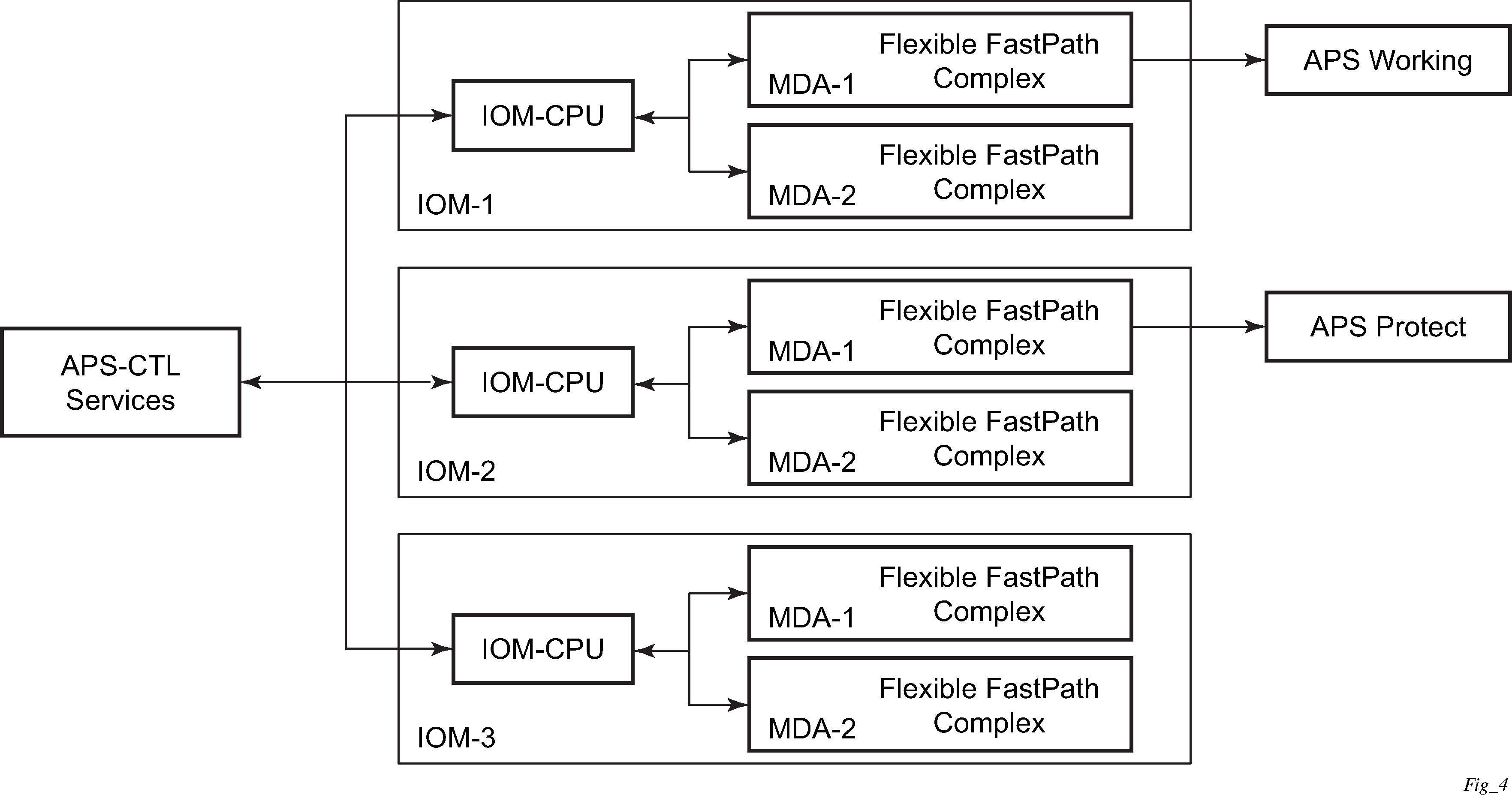
Switchover process for transmitted data
For packets arriving on all interfaces that need to be transmitted over APS protected interfaces, the next hop associated with all these interfaces are programmed in all Flexible Fast-Path complexes in each MDA with a logical next-hop index. This next hop-index identifies the actual next-hop information used to direct traffic to the APS working circuit on IOM-1/MDA-1.
All Flexible Fast-Path complexes in each MDA are also programmed with next hop information used to direct traffic to the APS protect circuit on IOM-2/MDA-1. When the transmitted data needs to be switched from the working to the protect circuit, only the relevant next hop indexes need to be changed to the pre-programmed next-hop information for the protect circuit on IOM-2/MDA-1.
Although the control CPM on the SF/CPM blade initiates the changeover between the working to protect circuit, the changeover is transparent to the upper layer protocols and service layers that the switchover occurs.
Physical link monitoring of the link is performed by the CPU on the relevant IOM for both working and protect circuits.
Switchover process for received data
The Flexible Fast-Path complexes for both working and protect circuits are programmed to process ingress. The inactive (protect) circuit however is programmed to ignore all packet data. To perform the switchover from working circuit to the protect circuit the Flexible Fast-Path complex for the working circuit is set to ignore all data while the Flexible Fast-Path complex of the protect circuit is changed to accept data.
The ADM or compatible head-end transmits a valid data signal to both the working and protection circuits. The signal on the protect line is ignored until the working circuit fails or degrades to the degree that requires a switchover to the protect circuit. When the switchover occurs all services including all their QoS and filter policies are activated on the protection circuit.
APS user-initiated requests
The following subsections describe APS user-initiated requests.
Lockout protection
The lockout of protection disables the use of the protection line. Because the tools>perform>aps>lockout command has the highest priority, a failed working line using the protection line is switched back to itself even if it is in a fault condition. No switches to the protection line are allowed when locked out.
Request switch of active to protection
The request or manual switch of active to protection command switches the active line to use the protection line unless a request of equal or higher priority is already in effect. If the active line is already on the protection line, no action takes place.
Request switch of active to working
The request or manual switch of active to working command switches the active line back from the protection line to the working line unless a request of equal or higher priority is already in effect. If the active line is already on the working line, no action takes place.
Forced switching of active to protection
The forced switch of active to protection command switches the active line to the protection line unless a request of equal or higher priority is already in effect. When the forced switch of working to protection command is in effect, it may be overridden either by a lockout of protection or by detecting a signal failure on the protection line. If the active line is already on the protection line, no action takes place.
Forced switch of active to working
The forced switch of active to working command switches the active line back from the protection line to the working unless a request of equal or higher priority is already in effect.
Exercise command
The exercise command is only supported in the bidirectional mode of the 1+1 architecture. The exercise command is specified in the tools>perform>aps>force>exercise context and exercises the protection line by sending an exercise request over the protection line to the tail-end and expecting a reverse request response back. The switch is not actually completed during the exercise routine.
APS and SNMP
SNMP Management of APS uses the APS-MIB (from rfc3498) and the TIMETRA-APS-MIB.
Switching mode to MIB mapping shows the mapping between APS switching modes and MIB objects.
| switching-mode | TIMETRA-APS-MIB tApsProtectionType |
APS-MIB apsConfigDirection |
|---|---|---|
Bidir 1+1 Sig APS (bidirectional) |
onePlusOneSignalling (1) |
bidirectional (2) |
Uni 1+1 Sig APS (unidirectional) |
onePlusOneSignalling (1) |
unidirectional (1) |
Uni 1+1 Sig+Data APS (uni-1plus1) |
onePlusOne (2) |
unidirectional (1) |
apsConfigMode in the APS-MIB is set to onePlusOneOptimized for Annex B operation.
APS applicability, restrictions, and interactions
Supported APS mode combinations shows the supported APS mode combinations.
APS switchover impact on statistics
All SAP-level statistics are retained with an APS switch. A SAP reflects the data received regardless of the number of APS switches that has occurred. ATM statistics, however, are cleared after an APS switch. Therefore, any ATM statistics viewed on an APS port are only the statistics since the current active member port became active.
Physical layer packet statistics on the APS group reflect what is currently on the active member port.
Port and path-level statistics follow the same behavior as described above.
Any SONET physical-layer statistics (for example, B1,B2,B3,...) on the APS port are only what is current on the active APS member port.
APS switchover during CPM switchover
An APS switchover immediately before, during or immediately after a CPM switchover may cause a longer outage than normal.
Removing or failure of a protect MDA
The detection of an MDA removal or an MDA failure can take additional time. This can affect the APS switchover time upon the removal or failure of a protection MDA. If the removal is scheduled during maintenance, it is recommended that the port and, or protect circuit be shutdown first to initiate an APS switchover before the MDA maintenance is performed.
Mirroring support
Mirroring parameters configured on a specific port or service, are maintained during an APS failover.
Example APS applications
The following subsections provide APS application examples.
Example APS application: MC-APS on channelized interfaces
The 7750 SR supports APS on channelized interfaces. This allows the router to be deployed as the radio access network (RAN) aggregation router which connects the base transceiver station (BTS) and the radio network controller (RNC).
E-LMI
The Ethernet Local Management Interface (E-LMI) protocol is defined in Metro Ethernet Forum (MEF) technical specification MEF16. This specification defines the protocol and procedures that convey the information for auto-configuration of a CE device and provides the means for EVC status notification. MEF16 does not include link management functions. In the Ethernet context that role is already accomplished with Clause 57 Ethernet OAM (formerly 802.3ah).
The SR OS currently implements the User Network Interface-Network (UNI-N) functions for status notification supported on Ethernet access ports with dot1q encapsulation type. Notification related to status change of the EVC and CE-VLAN ID to EVC mapping information is provided as a one to one between SAP and EVC.
The E-LMI frame encapsulation is based on IEEE 802.3 untagged MAC frame format using an ether-type of 0x88EE. The destination MAC address of the packet 01-80-C2-00-00-07 is dropped by any 802.1d compliant bridge that does not support or have the E-LMI protocol enabled. This means the protocol cannot be tunneled.
Status information is sent from the UNI-N to the UNI-C, either because a status inquiry was received from the UNI-C or unsolicited. The Active and Not Active EVC status are supported. The Partially Active state is left for further study.
The bandwidth profile sub-information element associated with the EVC Status IE does not use information from the SAP QoS policy. A value of 0 is used in this release as MEF 16 indicates the bandwidth profile sub-IE is mandatory in the EVC Status IE. The EVC identifier is set to the description of the SAP and the UNI identifier is set to the description configured on the port. Further, the implementation associates each SAP with an EVC. Currently, support exists for CE-VLAN ID/EVC bundling mode.
The E-LMI the UNI-N can participate in the OAM fault propagation functions. This is a unidirectional update from the UNI-N to the UNI-C and interacting with service manager of VLL, VPLS, VPRN and IES services.
LLDP
The IEEE 802.1ab Link Layer Discovery Protocol (LLDP) standard defines protocol and management elements that are suitable for advertising information to stations attached to the same IEEE 802 LAN (emulation) for the purpose of populating physical or logical topology and device discovery management information databases. The protocol facilitates the identification of stations connected by IEEE 802 LANs/MANs, their points of interconnection, and access points for management protocols.
Note that LAN emulation and logical topology wording is applicable to customer bridge scenarios (enterprise/carrier of carrier) connected to a provider network offering a transparent LAN emulation service to their customers. It helps the customer bridges detect misconnection by an intermediate provider by offering a view of the customer topology where the provider service is represented as a LAN interconnecting these customer bridges.
The IEEE 802.1ab standard defines a protocol that:
-
Advertises connectivity and management information about the local station to adjacent stations on the same IEEE 802 LAN.
-
Receives network management information from adjacent stations on the same IEEE 802 LAN.
-
Establishes a network management information schema and object definitions that are suitable for storing connection information about adjacent stations.
Attributes of the IEEE 802.1ab standard include:
-
Operating with all IEEE 802 access protocols and network media.
-
Providing compatibility with a number of MIBs as shown in LLDP internal architecture for a network node.
Figure 16. LLDP internal architecture for a network node 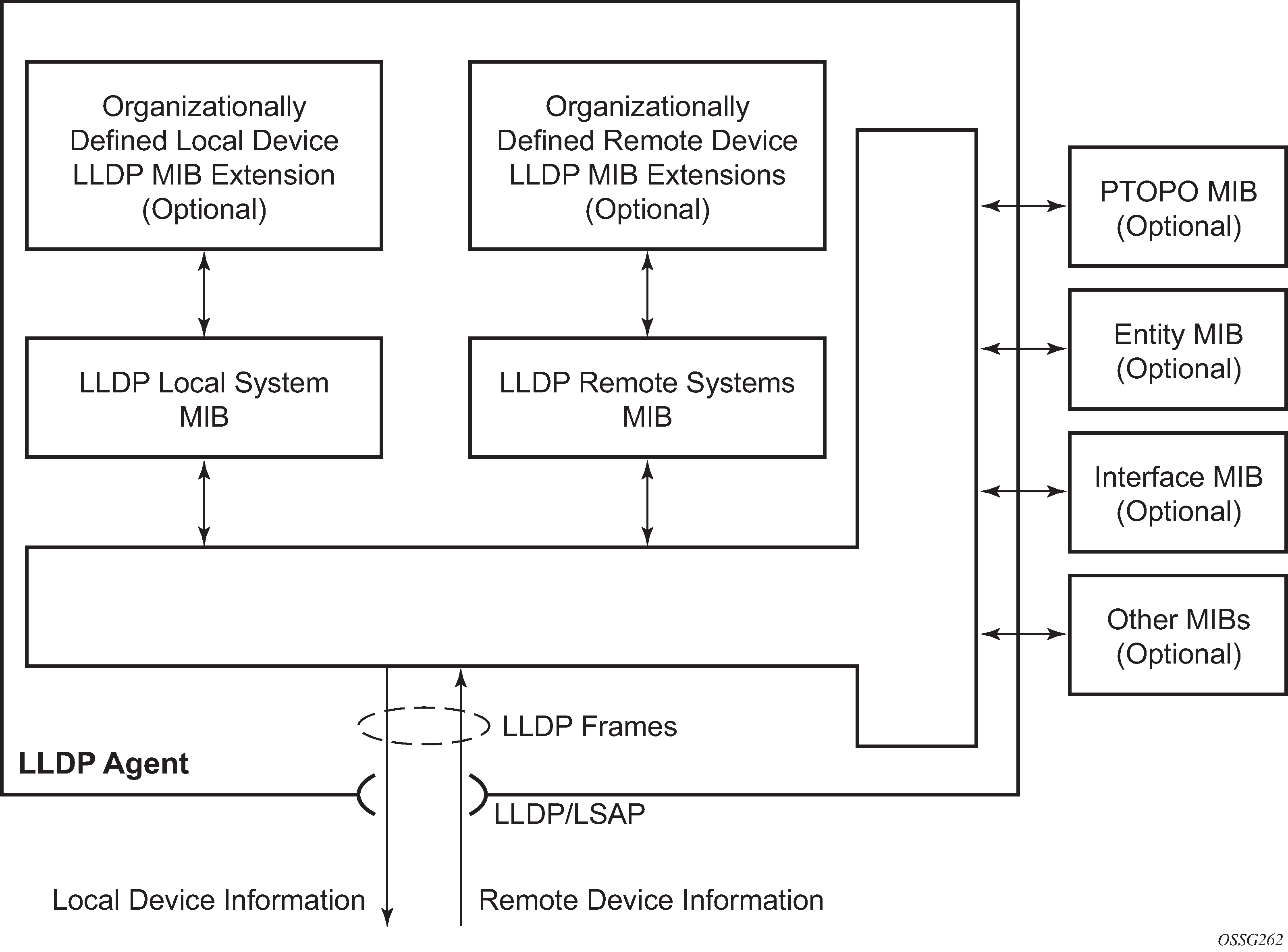
Network operators must be able to discover the topology information to detect and address network problems and inconsistencies in the configuration. Moreover, standard-based tools can address the complex network scenarios where multiple devices from different vendors are interconnected using Ethernet interfaces.
The example shown in Generic customer use case For LLDP depicts a MPLS network that uses Ethernet interfaces in the core or as an access/handoff interfaces to connect to different kind of Ethernet enabled devices such as service gateway/routers, QinQ switches, DSLAMs or customer equipment.
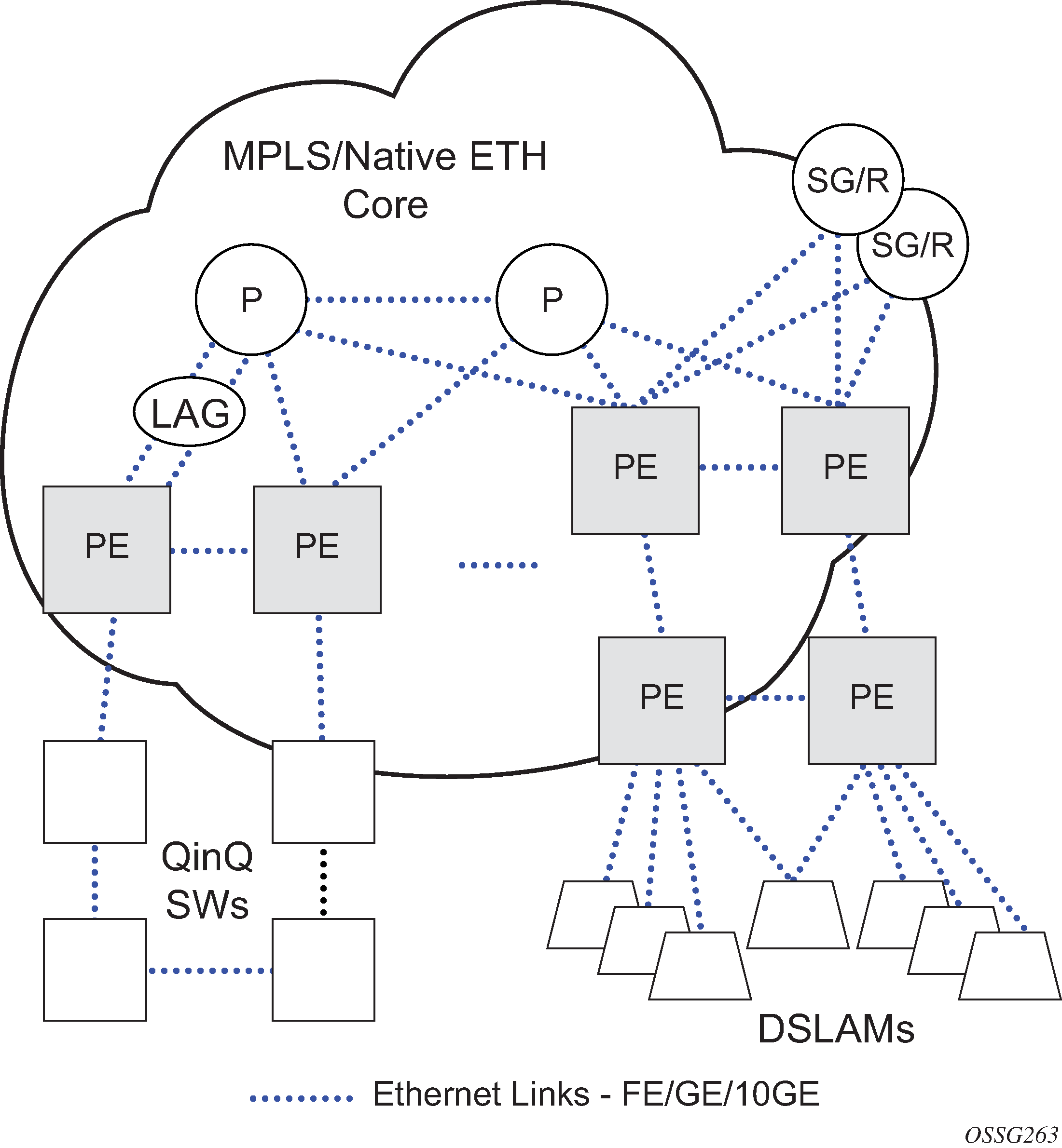
IEEE 802.1ab LLDP running on each Ethernet interfaces in between all the above network elements may be used to discover the topology information.
Operators who are utilizing IOM/IMM can tunnel the nearest-bridge at the port level using the tunnel-nearest-bridge command under the config>port>ethernet>lldp>destmac (nearest-bridge) hierarchy. The dest-mac nearest-bridge must be disabled for tunneling to occur.
LLDP protocol features
LLDP is a unidirectional protocol that uses the MAC layer to transmit specific information related to the capabilities and status of the local device. Separately from the transmit direction, the LLDP agent can also receive the same kind of information for a remote device which is stored in the related MIBs.
LLDP itself does not contain a mechanism for soliciting specific information from other LLDP agents, nor does it provide a specific means of confirming the receipt of information. LLDP allows the transmitter and the receiver to be separately enabled, making it possible to configure an implementation so the local LLDP agent can either transmit only or receive only, or can transmit and receive LLDP information.
The information fields in each LLDP frame are contained in an LLDP Data Unit (LLDPDU) as a sequence of variable length information elements, that each include type, length, and value fields (known as TLVs), where:
Type identifies what kind of information is being sent.
Length indicates the length of the information string in octets.
Value is the actual information that needs to be sent (for example, a binary bit map or an alphanumeric string that can contain one or more fields).
Each LLDPDU contains four mandatory TLVs and can contain optional TLVs as selected by network management:
Chassis ID TLV
Port ID TLV
Time To Live TLV
Zero or more optional TLVs, as allowed by the maximum size of the LLDPDU
End Of LLDPDU TLV
The chassis ID and the port ID values are concatenated to form a logical identifier that is used by the recipient to identify the sending LLDP agent/port. Both the chassis ID and port ID values can be defined in a number of convenient forms. After selected however, the chassis ID/port ID value combination remains the same as long as the particular port remains operable.
A non-zero value in the TTL field of the Time To Live TLV tells the receiving LLDP agent how long all information pertaining to this LLDPDU’s identifier is valid so that all the associated information can later be automatically discarded by the receiving LLDP agent if the sender fails to update it in a timely manner. A zero value indicates that any information pertaining to this LLDPDU’s identifier is to be discarded immediately.
A TTL value of zero can be used, for example, to signal that the sending port has initiated a port shutdown procedure. The End Of LLDPDU TLV marks the end of the LLDPDU.
The implementation defaults to setting the port-id field in the LLDP OAMPDU to tx-local. This encodes the port-id field as ifIndex (sub-type 7) of the associated port. Some network management systems use the ifIndex value to properly build the Layer Two Topology Network Map. However, this numerical value is difficult to interpret or readily identify the LLDP peer. Configuration options are available to control the encoding of the port-id information and the associated subtype using the port-id-subtype option. Three options are supported for the port-id-subtype:
- tx-if-alias
- transmits the ifAlias String (subtype 1) that describes the port as stored in the IF-MIB, either user configured description or the default entry (10/100/Gig Ethernet SFP)
- tx-if-name
- transmits the ifName string (subtype 5) that describes the port as stored in the IF-MIB, ifName info
- tx-local
- the interface ifIndex value (subtype 7)
IPv6 (address subtype 2) and IPv4 (address subtype 1) LLDP System Management addresses are supported. The IP addresses can be selected from the system IP addressing, the out-of-band management address (BOF), or both.
If the port-desc TLV is enabled it has a maximum of 255 byte limit. However, truncation of the port description information occurs if the combination of the port-id and the ifDesc (for example 1/1/c1/2, 10-Gig Ethernet) exceeds the 255 byte maximum. The truncation of the port description information is equal to the number of bytes required to include the ifDesc.
Exponential Port Dampening
Exponential Port Dampening (EPD) provides the ability to automatically block a port from reuse for a period of time after physical link-down and physical link-up events. If a series of down-up events occur close together, EPD keeps the port’s operational state down for a longer period than if only one down-up event has occurred. The router avoids using that port if external events are causing the link state to fluctuate. The more events that occur, the longer the port is kept down and avoided by the routing protocols.
EPD behavior uses a fixed penalty amount per link-down event and a half-life decay equation to reduce these penalties over time. The following equation defines exponential decay:
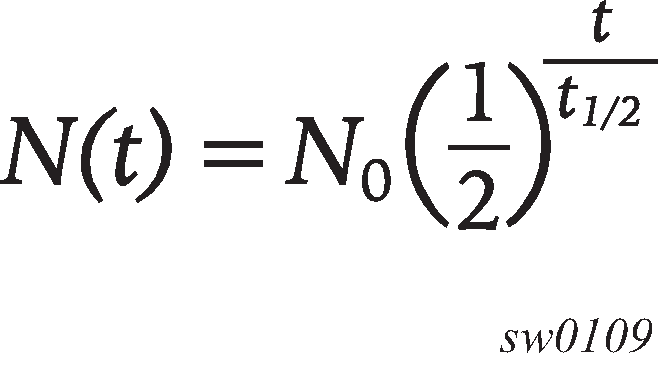
where:
N(t) is the quantity that still remains after a time t
N0 is the initial quantity
t½ is the half-life
In dampening, N0 refers to the starting penalties from the last link-down event. The quantity N(t) refers to the decayed penalties at a specific time, and is calculated starting from the last link-down event (that is, from the time when N0 last changed).
This equation can also be used on a periodic basis by updating the initial quantity value N0 each period and then computing the new penalty over the period (t).
The following figure shows an example usage of the EDP feature.
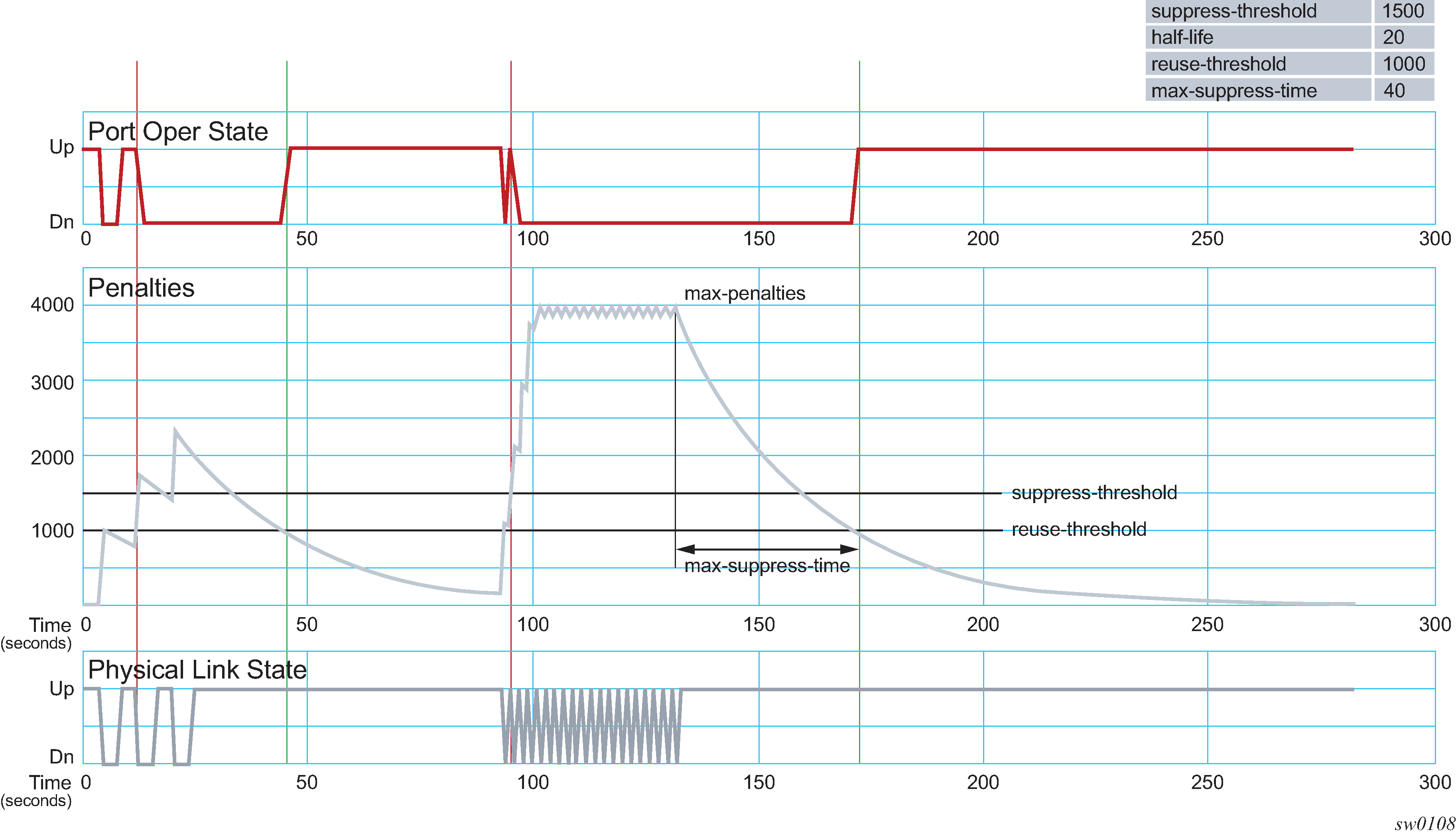
At time (t = 0) in the preceding figure, the initial condition has the link up, the accumulated penalties are zero, the dampening state is idle, and the port operational state is up. The following series of events and actions occur.
t = 5: link-down event
the accumulated penalties are incremented by 1000
the accumulated penalties now equal 1000, which is less than the suppress threshold (of 1500), so the dampening state is idle
because the dampening state is idle, link-down is passed to the upper layer
link-down triggers the port operational state to down
t = 9: link-up event
the accumulated penalties equal 869, which is less than the suppress threshold, so the dampening state remains as idle
because the dampening state is idle, link-up is passed to the upper layer
link-up triggers the port operational state to up
t = 13: link-down event
the accumulated penalties are incremented by 1000
the accumulated penalties now equal 1755, which is greater than the suppress threshold, so the dampening state is changed to active
because the dampening state just transitioned to active, link-down is passed to the upper layer
link-down triggers the port operational state to down
t = 17: link-up event
the accumulated penalties equal 1527, which is above the reuse threshold (of 1000) and greater than the suppress threshold, so the dampening state remains as active
because the dampening state is active, link-up is not passed to the upper layer
the port operational state remains down
t = 21: link-down event
the accumulated penalties are incremented by 1000
the accumulated penalties now equal 2327, which is above the reuse threshold, so the dampening state remains as active
because the dampening state is active, link-down is not passed to the upper layer
the port operational state remains down
t = 25: link-up event
the accumulated penalties equal 2024, which is above the reuse threshold, so dampening state remains as active
because the dampening state is active, link-up is not passed to the upper layer
the port operational state remains down
t = 46: accumulated penalties drop below the reuse threshold
the accumulated penalties drop below the reuse threshold, so the dampening state changes to idle
because the dampening state is idle and the current link state is up, link-up is passed to the upper layer
the port operational state changes to up
t = 94 to 133: link-down and link-up events every second
similar to previous events, the accumulated penalties increment on every link-down event
the dampening state transitions to active at t = 96, and link state events are not sent to the upper layer after that time
the upper layer keeps the port operational state down after t = 96
the accumulated penalties increment to a maximum of 4000
t = 133: final link event of link-up
the accumulated penalties equal 3863
the dampening state remains active and link state events are not sent to the upper layer
the upper layer keeps the port operational state down
t = 172: accumulated penalties drop below the reuse threshold
the accumulated penalties drop below the reuse threshold, so the dampening state changes to idle
because the dampening state is idle and the current link state is up, link-up is passed to the upper layer
the port operational state changes to up
Per port aggregate egress queue statistics monitoring
Monitoring the aggregate egress queue statistics per port provides in-profile, out-of-profile, and total statistics for both forwarded and dropped packets and octets on a specific port.
When enabled, all queues on the port are monitored, including SAP egress, network egress, subscriber egress, and egress queue group queues, as well as system queues which can be used, for example, to send port-related protocol packets (LACP, EFM, and so on).
This is enabled and disabled using the following command:
config port <port-id> [no] monitor-agg-egress-queue-stats
When enabled, the line card polls the related queues to derive the aggregates which provide the delta of the queue statistics since turning on the monitoring. This means that the reported statistics are not reduced by those from a deleted queue and so the aggregates correctly represent the forwarded/dropped statistics since the start of monitoring.
The aggregates can be shown with the following command:
show port [<port-id>] [statistics [egress-aggregate]] [detail]
As an example, the output below enables monitoring of aggregate egress queue statistics on port 2/1/1 and then shows the monitored statistics:
*A:PE# configure port 2/1/1 monitor-agg-egress-queue-stats
*A:PE# show port 2/1/1 statistics egress-aggregate

===============================================================================
Port 2/1/1 Egress Aggregate Statistics on Slot 2
===============================================================================
                         Forwarded                Dropped                  Total
-------------------------------------------------------------------------------
PacketsIn                     144                      0                    144
PacketsOut                      0                      0                      0
OctetsIn                    12353                      0                  12353
OctetsOut                       0                      0                      0
===============================================================================
*A:PE#
To clear the aggregate statistics, the monitoring must be disabled and then re-enabled. The aggregate statistics are also cleared when the card is cleared (using a clear card slot-number command) or power-cycled (with the tools perform card slot-id command). Additionally, aggregate statistics related to MDA are cleared when the MDA is cleared (using the clear mda mda-id command) or the MDA is inserted into an IOM. The aggregate statistics are not cleared when a shutdown/no shutdown is performed on the card and, or MDA.
There is no specific limit on the number of queues that can be monitored, but the amount of each line card's CPU resources allocated to the monitoring is bounded; consequently, when more queues on a card’s ports are monitored, the aggregate statistics are updated the less frequently.
Monitoring of aggregate statistics is supported on PXC sub-ports but not on a PXC physical port. It is also not supported on satellite ports.
Forward Error Correction
Users can use Forward Error Correction (FEC) on some ports to improve either the transmission reliability or reach, or both. FEC must always be used on some interface types while it is optional for other interface types. Also, some interface types allow more than one type of FEC. No matter what the setting of the FEC attributes, the transmitter and the receiver must have the same configuration, or the link will not work. The setting of FEC on a specific port is dependent on the interface type and the specific optical transceiver in use. Contact your Nokia representative for information about the options based on the transceiver in use.