VLL services
Circuit emulation services
This section provides information about Circuit Emulation (Cpipe) services. Cpipe is supported for the 7450 ESS and 7750 SR only.
Circuit emulation modes
Two modes of circuit emulation are supported: unstructured and structured. Unstructured mode is supported for DS1 and E1 channels per RFC 4553, Structure-Agnostic Time Division Multiplexing (TDM) over Packet (SAToP). Structured mode is supported for N*64 kb/s circuits as per RFC 5086, Structure-Aware Time Division Multiplexed (TDM) Circuit Emulation Service over Packet Switched Network (CESoPSN). Also, DS1, E1, and N*64 kb/s circuits are supported (per MEF8). TDM circuits are optionally encapsulated in MPLS or Ethernet as per the referenced standards in the following examples.
The following figure shows an example of RFC 4553 (SAToP) MPLS PSN encapsulation.

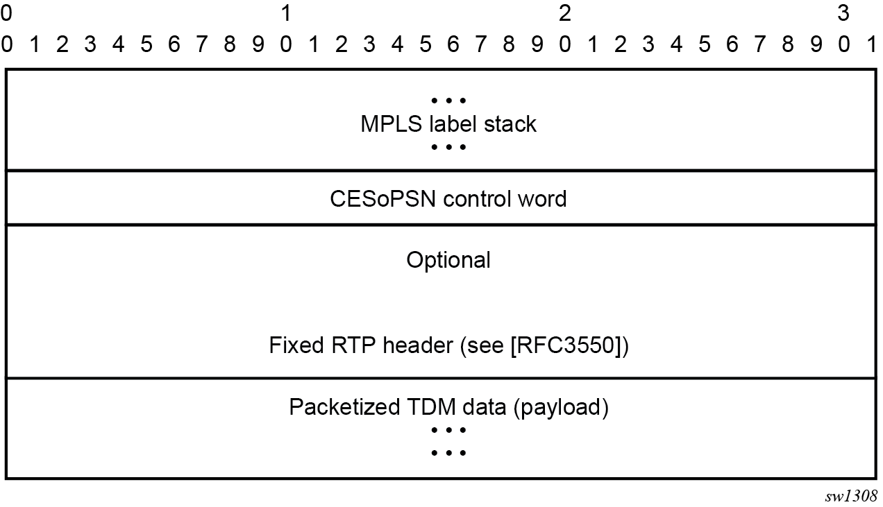
The following figure shows an example of CESoPSN packet format for an MPLS PSN.
The following figure shows an example of MEF8 PSN encapsulation.

Circuit emulation parameters
Circuit emulation modes
All channels on the CES MDA are supported as circuits to be emulated across the packet network. Structure-aware mode is supported for N*64 kb/s channel groups in DS1 and E1 carriers. Fragmentation is not supported for circuit emulation packets (structured or unstructured).
For DS1 and E1 unstructured circuits, the framing can be set to unframed. When channel group 1 is created on an unframed DS1 or E1, it is automatically configured to contain all 24 or 32 channels, respectively.
N*64 kb/s circuit emulation supports basic and Channel Associated Signaling (CAS) options for timeslots 1 to 31 (channels 2 to 32) on E1 carriers and channels 1 to 24 on DS1 carriers. CAS in-band is supported; therefore, no separate pseudowire support for CAS is provided. CAS option can be enabled or disabled for all channel groups on a specific DS1 or E1. If CAS operation is enabled, timeslot 16 (channel 17) cannot be included in the channel group on E1 carriers. Control channel signaling (CCS) operation is not supported.
Absolute mode option
For all circuit emulation channels except those with differential clock sources, RTP headers in absolute mode can be optionally enabled (disabled by default). For circuit emulation channels that use differential clock sources, this configuration is blocked. All channel groups on a specific DS1 or E1 can be configured for the same mode of operation.
When enabled for absolute mode operation, an RTP header is inserted. On transmit, the CES IWF inserts an incrementing (by 1 for each packet) timestamp into the packets. All other fields are set to zero. The RTP header is ignored on receipt. This mode is enabled for interoperability purposes only for devices that require an RTP header to be present.
Payload size
For DS3, E3, DS1, and E1 circuit emulation, the payload size can be configurable in number of octets. The default values for this parameter are shown in Unstructured payload defaults. Unstructured payload sizes can be set to a multiple of 32 octets and minimally be 64 octets. TDM satellite supports only unstructured payloads.
| TDM circuit | Default payload size |
|---|---|
DS1 |
192 octets |
E1 |
256 octets |
For N*64 kb/s circuits, the number of octets or DS1/E1 frames to be included in the TDM payload needs to be configurable in the range 4 to 128 DS1/E1 frames in increments of 1 or the payload size in octets. The default number of frames is shown in Structured number of default frames with associated packet sizes. For the number of 64 kb/s channels included (N), the following number of default frames apply for no CAS: n=1, 64 frames; 2≤N≤ 4, 32 frames; 5≤N≤ 15, 16 frames; N≥16, 8 frames.
For CAS circuits, the number of frames can be 24 for DS1 and 16 for E1, which yields a payload size of N*24 octets for T1 and N*16 octets for E1. For CAS, the signaling portion is an additional ((N+1)/2) bytes, where N is the number of channels. The additional signaling bytes are not included in the TDM payload size, although they are included in the actual packet size shown in Structured number of default frames.
The full ABCD signaling value can be derived before the packet is sent. This occurs for every 24 frames for DS1 ESF and every 16 frames for E1. For DS1 SF, ABAB signaling is actually sent because SF framing only supports AB signaling every 12 frames.
| Num timeslots | No CAS | DS1 CAS | E1 CAS | ||||
|---|---|---|---|---|---|---|---|
| num-frames default | Default payload | Minimum payload | Payload (24 frames) | Packet size | Payload (16 frames) | Packet size | |
1 |
64 |
64 |
40 |
24 |
25 |
16 |
17 |
2 |
32 |
64 |
64 |
48 |
49 |
32 |
33 |
3 |
32 |
96 |
96 |
72 |
74 |
48 |
50 |
4 |
32 |
128 |
128 |
96 |
98 |
64 |
66 |
5 |
16 |
80 |
80 |
120 |
123 |
80 |
83 |
6 |
16 |
96 |
96 |
144 |
147 |
96 |
99 |
7 |
16 |
112 |
112 |
168 |
172 |
112 |
116 |
8 |
16 |
128 |
128 |
192 |
196 |
128 |
132 |
9 |
16 |
144 |
144 |
216 |
221 |
144 |
149 |
10 |
16 |
160 |
160 |
240 |
245 |
160 |
165 |
11 |
16 |
176 |
176 |
264 |
270 |
176 |
182 |
12 |
16 |
192 |
192 |
288 |
294 |
192 |
198 |
13 |
16 |
208 |
208 |
312 |
319 |
208 |
215 |
14 |
16 |
224 |
224 |
336 |
343 |
224 |
231 |
15 |
16 |
240 |
240 |
360 |
368 |
240 |
248 |
16 |
8 |
128 |
128 |
384 |
392 |
256 |
264 |
17 |
8 |
136 |
136 |
408 |
417 |
272 |
281 |
18 |
8 |
144 |
144 |
432 |
441 |
288 |
297 |
19 |
8 |
152 |
152 |
456 |
466 |
304 |
314 |
20 |
8 |
160 |
160 |
480 |
490 |
320 |
330 |
21 |
8 |
168 |
168 |
504 |
515 |
336 |
347 |
22 |
8 |
176 |
176 |
528 |
539 |
352 |
363 |
23 |
8 |
184 |
184 |
552 |
564 |
368 |
380 |
24 |
8 |
192 |
192 |
576 |
588 |
384 |
396 |
25 |
8 |
200 |
200 |
— |
— |
400 |
413 |
26 |
8 |
208 |
208 |
— |
— |
416 |
429 |
27 |
8 |
216 |
216 |
— |
— |
432 |
446 |
28 |
8 |
224 |
224 |
— |
— |
448 |
462 |
29 |
8 |
232 |
232 |
— |
— |
464 |
479 |
30 |
8 |
240 |
240 |
— |
— |
480 |
495 |
31 |
8 |
248 |
248 |
— |
— |
— |
— |
Jitter buffer
For each circuit, the maximum receive jitter buffer is configurable. Packet delay from this buffer starts when the buffer is 50% full, to give an operational packet delay variance (PDV) equal to 75% of the maximum buffer size. The default value for the jitter buffer is nominally 5 ms. However, for lower-speed N*64 kb/s circuits and CAS circuits, the following default values are used to align with the default number of frames (and resulting packetization delay) to allow at least two frames to be received before starting to playout the buffer. The jitter buffer is at least four times the packetization delay. The following default jitter buffer values for structured circuits apply:
Basic CES (DS1 and E1):
N=1, 32 ms
2≤N≤4, 16 ms
5≤N≤15, 8 ms
N≥16, 5 ms
CES circuit operation
The circuit status can be tracked to be either up, loss of packets, or administratively down. Statistics are available for the number of in-service seconds and the number of out-of-service seconds when the circuit is administratively up.
Jitter buffer overrun and underrun counters are available by statistics and optionally logged while the circuit is up. On overruns, excess packets are discarded and counted. On underruns, all ones are sent for unstructured circuits. For structured circuits, all ones or a user-defined data pattern is sent based on configuration. Also, if CAS is enabled, all ones or a user-defined signaling pattern is sent based on configuration.
For each CES circuit, alarms can be optionally disabled/enabled for stray packets, malformed packets, packet loss, receive buffer overrun, and remote packet loss. An alarm is raised if the defect persists for 3 seconds, and cleared when the defect no longer persists for 10 seconds. These alarms are logged and trapped when enabled.
Services for transporting CES circuits
Each circuit can be optionally encapsulated in MPLS, Ethernet packets. Circuits encapsulated in MPLS use circuit pipes (Cpipes) to connect to the far-end circuit. Cpipes support either SAP spoke-SDP or SAP-SAP connections. Cpipes are supported over MPLS and GRE tunnels. The Cpipe default service MTU is set to 1514 bytes.
Circuits encapsulated in Ethernet can be selected as a SAP in Epipes. Circuits encapsulated in Ethernet can be SAP spoke-SDP connections or Ethernet CEM SAP-to-Ethernet SAP for all valid Epipe SAPs. Circuits requiring CEM SAP-to-CEM SAP connections use Cpipes. A local and remote EC-ID and far-end destination MAC address can be configurable for each circuit. The MDA MAC address is used as the source MAC address for these circuits.
For all service types, there are deterministic PIR=CIR values with class=EF parameters based on the circuit emulation parameters.
All circuit emulation services support the display of status of up, loss of packet (LOP), or admin down. Also, any jitter buffer overruns or underruns are logged.
Non-stop services are supported for Cpipes and CES over Epipes.
Network synchronization considerations
Each OC-3/STM-1 port can be independently configured to be loop-timed or node-timed. Each OC-3/STM-1 port can be configured to be a timing source for the node. TDM satellites only support node-timed mode.
Each DS-1 or E-1 channel without CAS signaling enabled can be independently configured to be loop-timed, node-timed, adaptive-timed, or differential-timed. Each DS-1 or E-1 channel with CAS signaling enabled can be independently configured to be loop-timed or node-timed. Adaptive timing and differential timing are not supported on DS-1 or E-1 channels with CAS signaling enabled. For the TDM satellite, each DS1/E1 channel can be loop-timed, node-timed, or differential-timed.
The adaptive recovered clock of a CES circuit can be used as a timing reference source for the node (ref1 or ref2). This is required to distribute network timing to network elements that only have packet connectivity to the network. One timing source on the MDA can be monitored for timing integrity. Both timing sources can be monitored if they are configured on separate MDAs while respecting the timing subsystem slot requirements.
If a CES circuit is being used for adaptive clock recovery at the remote end (such that the local end is now an adaptive clock master), Nokia recommends setting the DS-1/E-1 to be node-timed to prevent potential jitter issues in the recovered adaptive clock at the remote device. This is not applicable to TDM satellites.
For differential-timed circuits, the following timestamp frequencies are supported: 103.68 MHz (for recommended >100 MHz operation), 77.76 MHz (for interoperability with SONET/SDH-based systems such as TSS-5) and 19.44 MHz (for Y.1413 compliance). TDM satellite supports only 77.76 MHz.
Adaptive and differential timing recovery must comply with published jitter and wander specifications (G.823, G.824, and G.8261) for traffic interfaces under typical network conditions and for synchronous interfaces under specified packet network delay, loss, and delay variance (jitter) conditions. The packet network requirements to meet the synchronous interface requirements are to be determined during the testing phase.
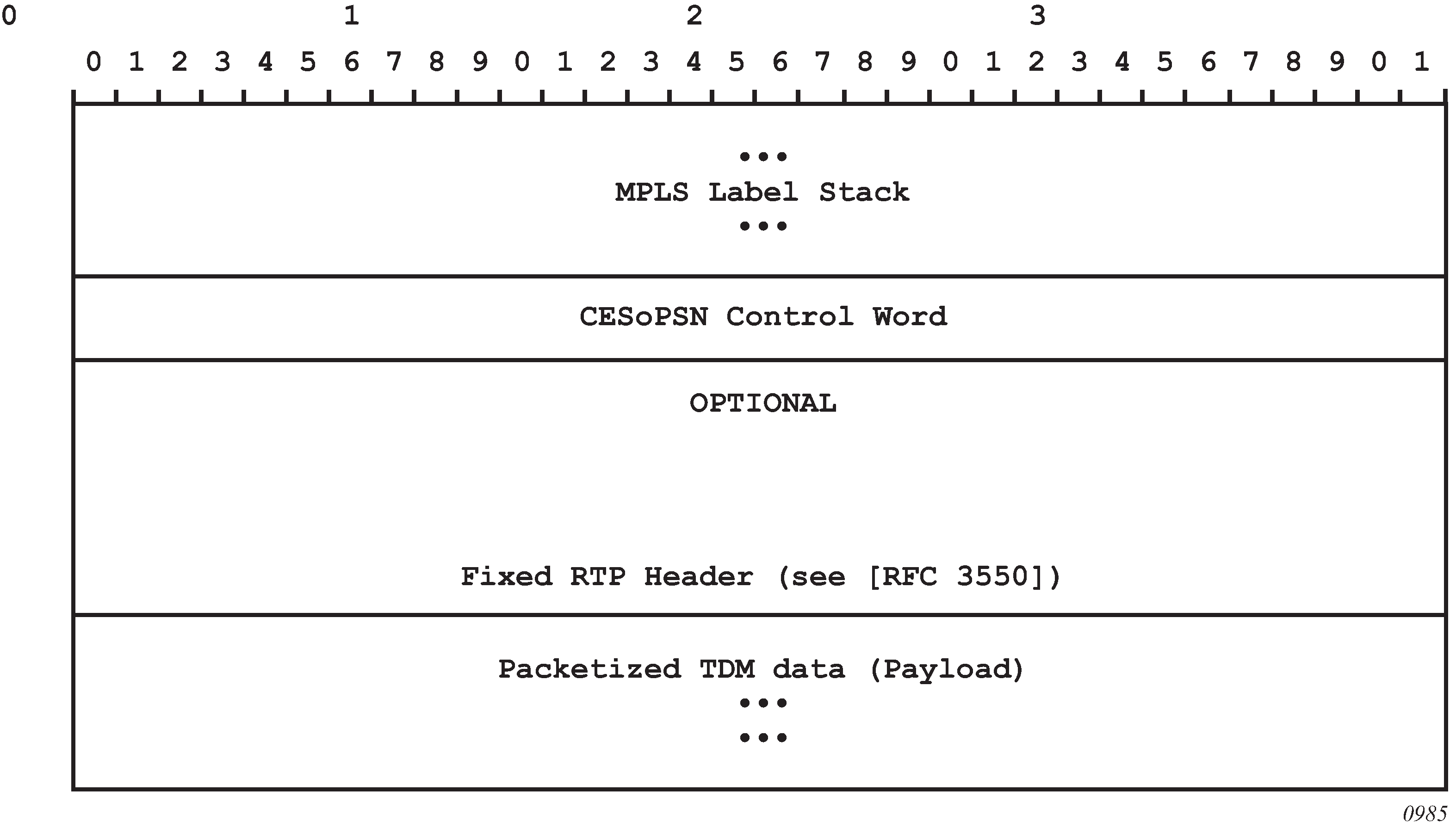
Cpipe payload
CESoPSN MPLS payload format shows the format of the CESoPSN TDM payload (with and without CAS) for packets carrying trunk-specific 64 kb/s service. In CESoPSN, the payload size is dependent on the number of timeslots used. This is not applicable to TDM satellite because only unstructured DS1/E1 is supported.
Ethernet pipe services
This section provides information about the Epipe service and implementation.
Epipe service overview
An Epipe service is the Nokia implementation of an Ethernet VLL based on the IETF "Martini Drafts" (draft-martini-l2circuit-trans-mpls-08.txt and draft-martini-l2circuit-encapmpls-04.txt) and the IETF Ethernet Pseudowire Draft (draft-so-pwe3-ethernet-00.txt).
An Epipe service is a Layer 2 point-to-point service where the customer data is encapsulated and transported across a service provider IP, MPLS, or Provider Backbone Bridging (PBB) VPLS network. An Epipe service is completely transparent to the customer data and protocols. The Epipe service does not perform any MAC learning. A local Epipe service consists of two SAPs on the same node, whereas a distributed Epipe service consists of two SAPs on different nodes. SDPs are not used in local Epipe services.
Each SAP configuration includes a specific port or channel on which service traffic enters the router from the customer side (also called the access side). Each port is configured with an encapsulation type. If a port is configured with an IEEE 802.1Q (referred to as dot1q) encapsulation, a unique encapsulation value (ID) must be specified.

Epipe service pseudowire VLAN tag processing
Distributed Epipe services are connected using a pseudowire, which can be provisioned statically or dynamically and is represented in the system as a spoke-SDP. The spoke-SDP can be configured to process zero, one, or two VLAN tags as traffic is transmitted and received; see Epipe spoke-SDP VLAN tag processing: ingress and Epipe-spoke SDP VLAN tag processing: egress for the ingress and egress tag processing. In the transmit direction, VLAN tags are added to the frame being sent. In the received direction, VLAN tags are removed from the frame being received. This is analogous to the SAP operations on a null, dot1q, and QinQ SAP.
The system expects a symmetrical configuration with its peer; specifically, it expects to remove the same number of VLAN tags from received traffic as it adds to transmitted traffic. When removing VLAN tags from a spoke-SDP, the system attempts to remove the configured number of VLAN tags. If fewer tags are found, the system removes the VLAN tags found and forwards the resulting packet.
Because some of the related configuration parameters are local and not communicated in the signaling plane, an asymmetrical behavior cannot always be detected and so cannot be blocked. With an asymmetrical behavior, a protocol extraction does not necessarily function as it would with a symmetrical configuration, resulting in an unexpected operation.
The VLAN tag processing is configured as follows on a spoke-SDP in an Epipe service:
zero VLAN tags processed
This requires the configuration of vc-type ether under the spoke-SDP, or in the related PW template.
one VLAN tag processed
This requires one of the following configurations:
vc-type vlan under the spoke-SDP or in the related PW template
vc-type ether and force-vlan-vc-forwarding under the spoke-SDP or in the related PW template
two VLAN tags processed
This requires the configuration of force-qinq-vc-forwarding [c-tag-c-tag | s-tag-c-tag] under the spoke-SDP or in the related PW template.
The PW template configuration provides support for BGP VPWS services.
The following restrictions apply to VLAN tag processing:
The configuration of vc-type vlan and force-vlan-vc-forwarding is mutually exclusive.
force-qinq-vc-forwarding [c-tag-c-tag | s-tag-c-tag] can be configured with the spoke-SDP signaled as either vc-type ether or vc-type vlan.
The following are not supported with force-qinq-vc-forwarding [c-tag-c-tag | s-tag-c-tag] configured under the spoke-SDP, or in the related PW template:
Multi-segment pseudowires.
PBB-Epipe services
force-vlan-vc-forwarding under the same spoke-SDP or PW template
Eth-CFM LM tests are NOT supported on UP MEPs when force-qinq-vc-forwarding is enabled.
Epipe spoke-SDP VLAN tag processing: ingress and Epipe-spoke SDP VLAN tag processing: egress describe the VLAN tag processing with respect to the zero, one, and two VLAN tag configuration described for the VLAN identifiers, Ethertype, ingress QoS classification (dot1p or DE), and QoS propagation to the egress (which can be used for egress classification and, or to set the QoS information in the innermost egress VLAN tag).
| Ingress (received on spoke-SDP) | Zero VLAN tags | One VLAN tag | Two VLAN tags (enabled by force-qinq-vc-forwarding [c-tag-c-tag | s-tag-c-tag] |
|---|---|---|---|
VLAN identifiers |
— |
Ignored |
Both inner and outer ignored |
Ethertype (to determine the presence of a VLAN tag) |
N/A |
0x8100 or value configured under sdp vlan-vc-etype |
Both inner and outer VLAN tags: 0x8100, or outer VLAN tag value configured under sdp vlan-vc-etype (inner VLAN tag value must be 0x8100) |
Ingress QoS (dot1p/DE) classification |
— |
Ignored |
Both inner and outer ignored |
QoS (dot1p/DE) propagation to egress |
Dot1p/DE=0 |
Dot1p/DE taken from received VLAN tag |
Dot1p/DE taken as follows:
The egress cannot be a spoke-sdp because force-qinq-vc-forwarding does not support multi-segment PWs. |
| Egress (sent on mesh or spoke-SDP) | Zero VLAN tags | One VLAN tag | Two VLAN tags (enabled by force-qinq-vc-forwarding [c-tag-c-tag | s-tag-c-tag] |
|---|---|---|---|
VLAN identifiers (set in VLAN tags) |
— |
The tag is derived from one of the following:
|
The inner and outer VLAN tags are derived from one of the following:
|
Ethertype (set in VLAN tags) |
— |
0x8100 or value configured under sdp vlan-vc-etype |
Both inner and outer VLAN tags: 0x8100, or outer VLAN tag value configured under sdp vlan-vc-etype (inner VLAN tag value is 0x8100) |
Egress QoS (dot1p/DE) (set in VLAN tags) |
— |
The tag taken from the innermost ingress service delimiting tag can be one of the following:
|
Inner and outer dot1p/DE: If c-tag-c-tag is configured, the inner and outer dot1p/DE bits are both taken from the innermost ingress service delimiting tag. It can be one of the following:
|
| 0 if there is no service delimiting VLAN tag at the ingress SAP or spoke-SDP Note that neither the inner nor outer dot1p/DE values can be explicitly set. |
If s-tag-c-tag is configured, the inner and outer dot1p/DE bits are taken from the inner and outer ingress service delimiting tag (respectively). They can be:
Note that neither the inner nor outer dot1p/DE values can be explicitly set. |
Any non-service delimiting VLAN tags are forwarded transparently through the Epipe service. SAP egress classification is possible on the outermost customer VLAN tag received on a spoke-SDP using the ethernet-ctag parameter in the associated SAP egress QoS policy.
Epipe up operational state configuration option
By default, the operational state of the Epipe is tied to the state of the two connections that comprise the Epipe. If either of the connections in the Epipe are operationally down, the Epipe service that contains that connection is also operationally down. The operator can configure a single SAP within an Epipe that does not affect the operational state of that Epipe, using the optional ignore-oper-state command. Within an Epipe, if a SAP that includes this optional command becomes operationally down, the operational state of the Epipe does not transition to down. The operational state of the Epipe remains up. This does not change that the SAP is down and no traffic can transit an operationally down SAP. Removing and adding this command on the fly evaluates the operational state of the service, based on the SAPs and the addition or deletion of this command.
Service OAM (SOAM) designers may consider using this command if an operationally up MEP configured on the operationally down SAP within an Epipe is required to receive and process SOAM PDUs. When a service is operationally down, this is not possible. For SOAM PDUs to continue to arrive on an operationally up, MEP configured on the failed SAP, the service must be operationally up. Consider the case where an operationally up MEP is placed on a UNI-N or E-NNI and the UNI-C on E-NNI peer is shutdown in such a way that it causes the SAP to become operationally down.
Two connections must be configured within the Epipe; otherwise, the service is operationally down regardless of this command. The ignore-oper-state functionality only operates as intended when the Epipe has one ingress and one egress. This command is not to be used for Epipe services with redundant connections that provide alternate forwarding in case of failure, even though the CLI does not prevent this configuration.
Support is available on Ethernet SAPs configured on ports or Ethernet SAPs configured on LAG. However, it is not allowed on SAPs using LAG profiles or if the SAP is configured on a LAG that has no ports.
Epipe with PBB
A PBB tunnel may be linked to an Epipe to a B-VPLS. MAC switching and learning is not required for the point-to-point service. All packets that ingress the SAP are PBB encapsulated and forwarded to the PBB tunnel to the backbone destination MAC address. Likewise, all the packets that ingress the B-VPLS destined for the ISID are PBB de-encapsulated and forwarded to the Epipe SAP. A fully specified backbone destination address must be provisioned for each PBB Epipe instance to be used for each incoming frame on the related I-SAP. If the backbone destination address is not found in the B-VPLS FDB, packets may be flooded through the B-VPLSs.
All B-VPLS constructs may be used including B-VPLS resiliency and OAM. Not all generic Epipe commands are applicable when using a PBB tunnel.
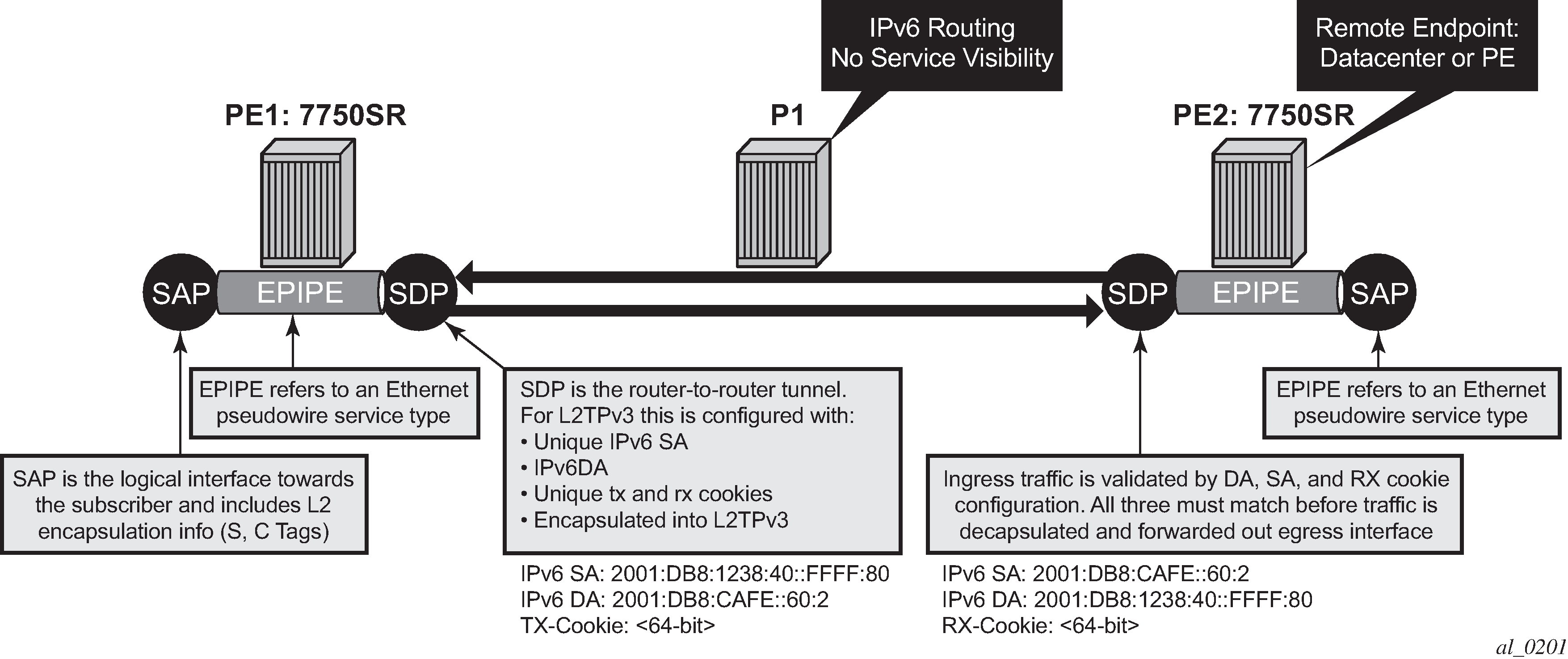
Epipe over L2TPv3
The L2TPv3 feature provides a framework to transport Ethernet pseudowire services over an IPv6-only network without MPLS. This architecture relies on the abundance of address space in the IPv6 protocol to provide unique far-end and local-end addressing that uniquely identify each tunnel and service binding.
L2TPv3 provides the capability of transporting multiple Epipes (up to 16K per system), by binding multiple IPv6 addresses to each node and configuring one SDP per Epipe.
Because the IPv6 addressing uniqueness identifies the customer and service binding, the L2TPv3 control plane is disabled in this mode.
L2TPv3 is supported on non-12e 7750 SR, 7450 ESS, and 7950 XRS platforms.
ETH-CFM is supported for OAM services.
Ethernet interworking VLL
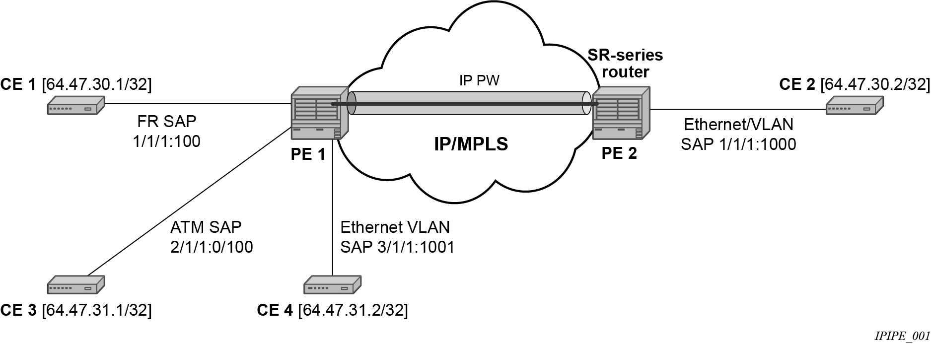
Application of Ethernet interworking VLL provides an example of an Ethernet interworking VLL. The Ethernet interworking VLL provides a point-to-point Ethernet VLL service between Frame Relay (FR) attached users, ATM-attached users, and Ethernet-attached users across an IP/MPLS packet switched network. It effectively provides ATM and FR bridged encapsulation termination on the existing Epipe service of the 7750 SR.
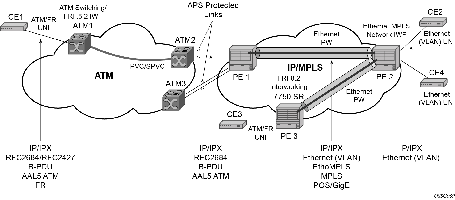
The following connectivity scenarios are supported:
a Frame Relay or ATM user connected to a ATM network communicating with a Ethernet user connected to a PE node on a IP/MPLS network
a Frame Relay or ATM user connected to PE node communicating with an Ethernet user connected to a PE node on an IP/MPLS network. This feature supports local cross-connecting when these users are attached to the same PE node.
Users attach over an ATM UNI with RFC 2684, Multiprotocol Encapsulation over ATM Adaptation Layer 5, tagged/untagged bridged Ethernet PDUs, a FR UNI using RFC 2427, Multiprotocol Interconnect over Frame Relay, tagged/untagged bridged Ethernet PDUs, or an Ethernet tagged/untagged UNI interface. However, the VCI/VPI and the data-link connection identifier (DLCI) are the identifiers of the SAP in the case of ATM and FR, respectively, and the received tags are transparent to the service, so are preserved.
The Ethernet pseudowire is established using T-LDP signaling and can use the ether or vlan VC types on the SDP. The SDP can be either an MPLS or GRE type.
VLL CAC
The VLL Connection Admission Control (CAC) is supported for the 7750 SR only and provides a method to administratively account for the bandwidth used by VLL services inside an SDP that consists of RSVP LSPs.
The service manager keeps track of the available bandwidth for each SDP. The SDP available bandwidth is applied through a configured booking factor. An administrative bandwidth value is assigned to the spoke-SDP. When a VLL service is bound to an SDP, the amount of bandwidth is subtracted from the adjusted available SDP bandwidth. When the VLL service binding is deleted from the SDP, the amount of bandwidth is added back into the adjusted SDP available bandwidth. If the total adjusted SDP available bandwidth is overbooked when adding a VLL service, a warning is issued and the binding is rejected.
This feature does not guarantee bandwidth to a VLL service because there is no change to the data path to enforce the bandwidth of an SDP by means such as shaping or policing of constituent RSVP LSPs.
MC-Ring and VLL
To support redundant VLL access in ring configurations, the multi-chassis ring (MC-Ring) feature is applicable to VLL SAPs. A conceptual drawing of the operation is shown in MC-Ring in a combination with VLL service. The specific CPE that is connected behind the ring node has access to both BSAs through the same VLAN provisioned in all ring nodes. There are two SAPs (with the same VLAN) provisioned on both nodes.
If a closed ring status occurs, one of the BSAs becomes the primary BSA and signals an active status bit on the corresponding VLL pseudowire. Similarly, the standby BSA signals a standby status. With this information, the remote node can choose the correct path to reach the CPE. In case of a broken ring, the node that can reach the ring node, to which the CPE is connected by RNCV check, becomes the primary and signals corresponding status on its pseudowire.
The mapping of individual SAPs to the ring nodes is done statically through CLI provisioning. To keep the convergence time to a minimum, MAC learning must be disabled on the ring node so all CPE originated traffic is sent in both directions. If the status is operationally down on the SAP on the standby BSA, that part of the traffic is blocked and not forwarded to the remote site.

For further information about Multi-Chassis Ring Layer 2 (with ESM), see the 7450 ESS, 7750 SR, and 7950 XRS Advanced Configuration Guide.
IP interworking VLL services
This section provides information about IP Interworking VLL (Ipipe) services.
Ipipe VLL
IP interworking VLL (Ipipe) provides an example of IP connectivity between a host attached to a point-to-point access circuit (FR, ATM, PPP) with routed PDU IPv4 encapsulation and a host attached to an Ethernet interface. Both hosts appear to be on the same LAN segment. This feature is supported for the 7450 ESS and 7750 SR and enables service interworking between different link layer technologies. A typical use of this application is in a Layer 2 VPN when upgrading a hub site to Ethernet while keeping the spoke sites with their existing Frame Relay or ATM IPv4 routed encapsulation.
IP interworking VLL datapath
In IP interworking VLL (Ipipe), PE 2 is manually configured with both CE 1 and CE 2 IP addresses. These are host addresses and are entered in /32 format. PE 2 maintains an ARP cache context for each IP interworking VLL. PE 2 responds to ARP request messages received on the Ethernet SAP. PE 2 responds with the Ethernet SAP configured MAC address as a proxy for any ARP request for CE 1 IP address. PE 2 silently discards any ARP request message received on the Ethernet SAP for an address other than that of CE 1. Likewise, PE 2 silently discards any ARP request message with the source IP address other than that of CE 2. In all cases, PE 2 keeps track of the association of IP to MAC addresses for ARP requests it receives over the Ethernet SAP.
To forward unicast frames destined for CE 2, PE 2 needs to know the CE 2 MAC address. When the Ipipe SAP is first configured and administratively enabled, PE2 sends an ARP request message for CE 2 MAC address over the Ethernet SAP. Until an ARP reply is received from CE2, providing the CE2 MAC address, unicast IP packets destined for CE2 are discarded at PE2. IP broadcast and IP multicast packets are sent on the Ethernet SAP using the broadcast or direct-mapped multicast MAC address.
To forward unicast frames destined for CE 1, PE 2 validates the MAC destination address of the received Ethernet frame. The MAC address should match that of the Ethernet SAP. PE 2 then removes the Ethernet header and encapsulates the IP packet directly into a pseudowire without a control word. PE 1 removes the pseudowire encapsulation and forwards the IP packet over the Frame Relay SAP using RFC 2427, Multiprotocol Interconnect over Frame Relay, routed PDU encapsulation.
To forward unicast packets destined for CE1, PE2 validates the MAC destination address of the received Ethernet frame. If the IP packet is unicast, the MAC destination must match that of the Ethernet SAP. If the IP packet is multicast or broadcast, the MAC destination address must be an appropriate multicast or broadcast MAC address.
The other procedures are similar to the case of communication between CE 1 and CE 2, except that the ATM SAP and the Ethernet SAP are cross-connected locally and IP packets do not get sent over an SDP.
A PE does not flush the ARP cache unless the SAP goes administratively or operationally down. The PE with the Ethernet SAP sends unsolicited ARP requests to refresh the ARP cache every ‟T” seconds. ARP requests are staggered at an increasing rate if no reply is received to the first unsolicited ARP request. The value of T is configurable by the user through the mac-refresh command.
Extension to IP VLL for discovery of Ethernet CE IP address
VLL services provide IP connectivity between a host attached to a point-to-point access circuit with routed PDU encapsulation and a host attached to an Ethernet interface. Both hosts appear to be on the same IP interface. This feature is supported only for IPv4 payload.
In deployments where it is not practical for operators to obtain and configure their customer CE address, the following behaviors apply:
A service comes up without prior configuration of the CE address parameter under both the SAP and the spoke-SDP.
Operators rely solely on received ARP messages from the Ethernet SAP-attached CE device to update the ARP cache with no further check of the validity of the source IP address of the ARP request message and the target IP address being resolved.
The LDP address list TLV signaling the learned CE IP address to the remote PE is supported. This is to allow the PE with the FR SAP to respond to an invFR ARP request message received from the FR-attached CE device. Only Ethernet SAP and FR SAP can learn the CE address through ARP and invFR ARP, respectively. The 7450 ESS and 7750 SR do not support invATM ARP on an ATM interface.
VLL Ethernet SAP processes
The operator can enable the following CE address discovery processes by configuring the ce-address-discovery in the config>service>ipipe context.
The service is brought up without the CE address parameter configured at either the SAP or the spoke-SDP.
The operator cannot configure the ce-address parameter under the config>service>ipipe>sap or config>service>ipipe>spoke-sdp context when the ce-address-discovery in the config>service>ipipe context is enabled. Conversely, the operator is not allowed to enable the ce-address-discovery option under the Ipipe service if it has a SAP and, or spoke-SDP with a user-entered ce-address parameter.
While an ARP cache is empty, the PE does not forward unicast IP packets over the Ethernet SAP but forwards multicast/broadcast packets. target IP address being resolved.
The PE waits for an ARP request from the CE to learn both IP and MAC addresses of the CE. Both entries are added into the ARP cache. The PE accepts any ARP request message received over Ethernet SAP and updates the ARP cache IP and MAC entries with no further check of the source IP address of the ARP request message or of the target IP address being resolved.
The 7450 ESS, 7750 SR, and 7950 XRS routers always reply to a received ARP request message from the Ethernet SAP with the SAP MAC address and a source IP address of the target IP address being resolved without any further check of the latter.
If the router received an address list TLV from the remote PE node with a valid IP address of the CE attached to the remote PE, the router does not check the CE IP address against the target IP address being resolved when replying to an ARP request over the Ethernet SAP.
The ARP cache is flushed when the SAP bounces or when the operator manually clears the ARP cache. This results in the clearing of the CE address discovered on this SAP. However, when the SAP comes up initially or comes back up from a failure, an unsolicited ARP request is not sent over the Ethernet SAP.
If the Ipipe service uses a spoke-SDP, the router includes the address list TLV in the interface parameters field of the pseudowire Forwarding Equivalent Class (FEC) TLV in the label mapping message. The address list TLV contains the current value of the CE address in the ARP cache. If no address was learned, an address value of 0.0.0.0 must be used.
If the remote PE included the address list TLV in the received label mapping message, the local router updates the remote PE node with the most current IP address of the Ethernet CE using a T-LDP notification message with the TLV status code set to 0x0000002C and containing an LDP address list. The notification message is sent each time an IP address different from the current value in the ARP cache is learned. This includes when the ARP is flushed and the CE address is reset to the value of 0.0.0.0.
If the remote PE did not include the address list TLV in the received label mapping message, the local router does not send any notification messages containing the address list TLV during the lifetime of the IP pseudowire.
If the operator disables the ce-address-discovery option under the VLL service, service manager instructs LDP to withdraw the service label and the service is shutdown. The pseudowire labels are only signaled and the service comes up if the operator re-enters the option again or manually enters the ce-address parameter under SAP and spoke-SDP.
VLL FR SAP procedures
The operator enables the following CE address dynamic learning procedures by enabling the ce-address-discovery option under the VLL service on the 7450 ESS or 7750 SR.
Allow the service to come up without the CE address parameter configured at both the SAP and spoke-SDP. If one or both parameters are configured, they are ignored.
The operator cannot configure the ce-address parameter under SAP or spoke-SDP when the ce-address-discovery option under the VLL service is enabled. Conversely, the operator is not allowed to enable the ce-address-discovery option under the Ipipe service if it has a SAP and, or spoke-SDP with a user-entered ce-address parameter.
If the router receives an invFR ARP request message over the FR SAP, it updates the ARP cache with the FR CE address. It also replies with the IP address of the CE attached to the remote PE if a valid address was advertised in the address list TLV by this remote PE. Otherwise, the router updates the ARP cache but does not reply to the invFR ARP.
If the Ipipe service uses a spoke-SDP, the router includes the address list TLV in the interface parameters field of the pseudowire FEC TLV in the label mapping message. The address list TLV contains the current value of the CE address in the ARP cache. If no address was learned, then an address value of 0.0.0.0 is used.
If the remote PE included the address list TLV in the received label mapping message, the local router updates the remote PE node with the most current IP address of the FR CE using a T-LDP status notification message containing an LDP address list. The notification message is sent each time an IP address different from the current value in the ARP cache is learned. This includes when the ARP is flushed and the CE address is reset to the value of 0.0.0.00.
If the remote PE did not include the address list TLV in the received label mapping message, the local router does not send any notification messages containing the address list TLV during the lifetime of the IP pseudowire.
VLL PPP/IPCP SAP procedures
The remote CE address can only be learned in the case of a PPP SAP but is not sent in the address list TLV to the remote PE in PPP SAP cases.
IPv6 support on IP interworking VLL
The 7450 ESS, 7750 SR, and 7950 XRS nodes support both the transport of IPv6 packets and the interworking of IPv6 Neighbor discovery/solicitation messages on an IP Interworking VLL. IPv6 capability is enabled on an Ipipe using the ce-address-discovery ipv6 command.
IPv6 Datapath operation
The IPv6 Datapath operation uses ICMPv6 extensions to automatically resolve IP address and link address associations. These are IP packets, as compared to ARP and invARP in IPv4, which are separate protocols and not based on IP packets. Manual configuration of IPv6 addresses is not supported on the IP Interworking VLL.
Each PE device intercepts ICMPv6 Neighbor Discovery (RFC 2461) packets, whether received over the SAP or over the pseudowire. The device inspects the packets to learn IPv6 interface addresses and CE link-layer addresses, modifies these packets as required according to the SAP type, then forwards them toward the original destination. The PE is also capable of generating packets to interwork between CEs (by using IPv6 Neighbor Discovery) and CEs that use other neighbor discovery protocols to bring up the link; for example, IPv6CP for PPP.
The PE device learns the IPv6 interface addresses for its directly-attached CE and other IPv6 interface addresses for the far-end CE. The PE device also learns the link-layer address of the local CE and uses it when forwarding traffic between the local and far-end CEs.
As with IPv4, the SAP accepts both unicast and multicast packets. For unicast packets, the PE checks that the MAC address/IP addresses are consistent with that in the ARP cache before forwarding; otherwise, the packet is silently discarded. Multicast packets are validated and forwarded. If more than one IP address is received per MAC address in a neighbor discovery packet, or if multiple neighbor discovery packets are received for a specific MAC address, the currently cached address is overwritten with the most recent value.
Data path for Ethernet CE to PPP attached CE shows the data path operation for IPv6 on an IP Interworking VLL between the Ethernet and PPP (IPv6CP) SAPs.

With reference to neighbor discovery between Ethernet and PPP CEs in Data path for Ethernet CE to PPP attached CE, the steps are as follows:
Ethernet-attached CE2 sends a Neighbor Solicitation message toward PE2 to begin the neighbor discovery process.
PE2 snoops this message, and the MAC address and IP address of CE2 is stored in the ARP cache of PE2 before forwarding the Neighbor Solicitation on the IP pseudowire to PE1.
PE1 snoops this message that arrives on the IP pseudowire and stores the IP address of the remote CE2. Because CE3 is attached to a PPP SAP, which uses IPv6CP to bring up the link, PE1 generates a neighbor advertisement message and sends it on the Ipipe toward PE2.
PE2 receives the neighbor advertisement on the Ipipe from PE1. It must replace the Layer 2 address in the neighbor advertisement message with the MAC address of the SAP before forwarding to CE2.
IPv6 stack capability signaling
The 7750 SR, 7450 ESS and 7950 XRS support IPv6 capability negotiation between PEs at the ends of an IP interworking VLL. Stack capability negotiation is performed if stack-capability-signaling is enabled in the CLI. Stack capability negotiation is disabled by default. Therefore, it must be assumed that the remote PE supports both IPv4 and IPv6 transport over an Ipipe.
A stack-capability sub-TLV is signaled by the two PEs using T-LDP so that they can agree on which stacks they should be using. By default, the IP pseudowire is always capable of carrying IPv4 packets. Therefore, this capability sub-TLV is used to indicate if other stacks need to be supported concurrently with IPv4.
The stack-capability sub-TLV is a part of the interface parameters of the pseudowire FEC. This means that any change to the stack support requires that the pseudowire be torn down and re-signaled.
A PE that supports IPv6 on an IP pseudowire must signal the stack-capability sub-TLV in the initial label mapping message for the pseudowire. For the 7750 SR, 7450 ESS, and 7950 XRS, this means that the stack-capability sub-TLV must be included if both the stack-capability-signaling and ce-address-discovery ipv6 options are enabled under the VLL service.
If one PE of an IP interworking VLL supports IPv6, while the far-end PE does not support IPv6 (or ce-address-discovery ipv6 is disabled), the pseudowire does not come up.
If a PE that supports IPv6 (that is, stack-capability-signaling ipv6 is enabled) has already sent an initial label mapping message for the pseudowire, but does not receive a stack-capability sub-TLV from the far-end PE in the initial label mapping message, or one is received but it is set to a reserved value, then the PE assumes that a configuration error has occurred. That is, if the remote PE did not include the stack-capability sub-TLV in the received label mapping message, or it does include the sub-TLV but with the IPv6 bit cleared, and if stack-capability-signaling is enabled, the local node with ce-address-discovery ipv6 enabled withdraws its pseudowire label with the LDP status code ‟IP Address type mismatch”.
If a 7750 SR, 7450 ESS, and 7950 XRS PE that supports IPv6 (that is, stack-capability-signaling ipv6 is enabled) has not yet sent a label mapping message for the pseudowire and does not receive a stack-capability sub-TLV from the far-end PE in the initial label mapping message, or one is received but it is set to a reserved value, the PE assumes that a configuration error has occurred and does not send a label mapping message of its own.
If the IPv6 stack is not supported by both PEs, or at least one of the PEs does support IPv6 but does not have the ce-address-discovery ipv6 option selected in the CLI, IPv6 packets received from the AC are discarded by the PE. IPv4 packets are always supported.
If IPv6 stack support is implemented by both PEs, but the ce-address-discovery ipv6 command was not enabled on both so that the IP pseudowire came up with only IPv4 support, and one PE is later toggled to ce-address-discovery ipv6, then that PE sends a label withdraw with the LDP status code meaning ‟Wrong IP Address Type” (Status Code 0x0000004B9).
If the IPv6 stack is supported by both PEs and, therefore, the pseudowire is established with IPv6 capability at both PEs, but the ce-address-discovery ipv6 command on one PE is later toggled to no ce-address-discovery ipv6 so that a PE ceases to support the IPv6 stack, then that PE sends a label withdraw with the LDP status code meaning ‟Wrong IP Address Type”.
Services configuration for MPLS-TP
MPLS-TP PWs are supported in Epipe and Cpipe VLLs and Epipe spoke termination on IES/VPRN and VPLS, I-VPLS, and B-VPLS on the 7450 ESS and 7750 SR only.
This section describes how SDPs and spoke-SDPs are used with MPLS-TP LSPs and static pseudowires with MPLS-TP OAM. It also describes how to conduct test service throughput for PWs, using lock instruct messages and loopback configuration.
MPLS-TP SDPs
Only MPLS SDPs are supported.
An SDP used for MPLS-TP supports the configuration of an MPLS-TP identifier as the far-end address as an alternative to an IP address. IP addresses are used if IP/MPLS LSPs are used by the SDP, or if MPLS-TP tunnels are identified by IPv4 source/destination addresses. MPLS-TP node identifiers are used if MPLS-TP tunnels are used.
Only static SDPs with signaling off support MPLS-TP spoke-SDPs.
The following CLI shows the MPLS-TP options:
config
   service
      sdp 10 [mpls | GRE | [ldp-enabled] [create]
         signaling <off | on>
         [no] lsp <xyz>
         [no] accounting-policy <policy-id>
         [no] adv-mtu-override
         [no] booking-factor <percentage>
         [no] class-forwarding
         [no] collect-stats
         [no] description <description-string>
         [no] far-end <ip-address> | [node-id
              {<ip-address> | <0…4,294,967,295>} [global-id <global-id>]]
         [no] tunnel-far-end <ip-address>
         [no] keep-alive
         [no] mixed-lsp-mode
         [no] metric <metric>
         [no] network-domain <network-domain-name>
         [no] path-mtu <mtu>
         [no] pbb-etype <ethertype>
         [no] vlan-vc-etype <ethertype>
         [no] shutdown
The far-end node-id ip-address global-id global-id command is used to associate an SDP far end with an MPLS-TP tunnel whose far-end address is an MPLS-TP node ID. If the SDP is associated with an RSVP-TE LSP, the far end must be a routable IPv4 address.
The system accepts the node-id being entered in either 4-octet IP address format (a.b.c.d) or unsigned integer format.
The SDP far end refers to an MPLS-TP node-id/global-id only if:
delivery type is MPLS
signaling is off
keep-alive is disabled
mixed-lsp-mode is disabled
adv-mtu-override is disabled
An LSP can only be allowed to be configured if the far-end information matches the lsp far end information (whether MPLS-TP or RSVP).
Only one LSP is allowed if the far end is an MPLS-TP node-id/global-id.
MPLS-TP or RSVP-TE LSPs are supported. However, LDP and BG LSPs are not blocked in CLI.
Signaling LDP or BGP is blocked if:
far-end node-id/global-id is configured
control-channel-status is enabled on any spoke (or mate vc-switched spoke)
pw-path-id is configured on any spoke (or mate vc-switched spoke)
IES/VPRN interface spoke control-word is enabled
The following commands are blocked if a far-end node-id/global-id is configured:
class-forwarding
tunnel-far-end
mixed-lsp-mode
keep-alive
ldp or bgp-tunnel
adv-mtu-override
VLL spoke SDP configuration
The system can be a T-PE or an S-PE for a pseudowire (a spoke-SDP) supporting MPLS-TP OAM. MPLS-TP related commands are applicable to spoke-SDPs configured under all services supported by MPLS-TP pseudowires. All commands and functions that are applicable to spoke-SDPs are supported, except for those that explicitly depend on T-LDP signaling of the pseudowire, or as stated following. Likewise, all existing functions on a specified service SAP are supported if the spoke-SDP that it is mated to is MPLS-TP.
The vc-switching is supported.
The following describes how to configure MPLS-TP on an Epipe VLL. However, a similar configuration applies to other VLL types.
A spoke-SDP bound to an SDP with the mpls-tp keyword cannot be no shutdown unless the ingress label, the egress label, the control word, and the pw-path-id are configured, as follows:
config
   service
      epipe
         [no] spoke-sdp sdp-id[:vc-id]
              [no] hash-label
              [no] standby-signaling-slave

         [no] spoke-sdp sdp-id[:vc-id] [vc-type {ether | vlan}]
             [create] [vc-switching] [no-endpoint | {endpoint [icb]}]
            egress
               vc-label <out-label>
            ingress
               vc-label <in-label>
            control-word
            bandwidth <bandwidth>
            [no] pw-path-id
               agi <agi>
               saii-type2 <global-id:node-id:ac-id>
               taii-type2 <global-id:node-id:ac-id>
               exit
            [no] control-channel-status
[no] refresh-timer <value>
request-timer <request-timer-secs> retry-timer <retry-timer-secs> timeout-
multiplier <multiplier>
no request-timer
               [no] acknowledgment
               [no] shutdown
               exit
The pw-path-id context is used to configure the end-to-end identifiers for an MS-PW. These may not coincide with those for the local node if the configuration is at an S-PE. The SAII and TAII are consistent with the source and destination of a label mapping message for a signaled PW.
The control-channel-status command enables static pseudowire status signaling. This is valid for any spoke-SDP where signaling none is configured on the SDP (for example, where T-LDP signaling is not in use). The refresh timer is specified in seconds, from 10-65535, with a default of 0 (off). This value can only be changed if control-channel-status is shutdown.
Commands that rely on PW status signaling are allowed if control-channel-status is configured for a spoke-SDP bound to an SDP with signaling off, but the system uses control channel status signaling instead of T-LDP status signaling. The ability to configure control channel status signaling on a specified spoke-SDP is determined by the credit-based algorithm described earlier. Control channel status for a pseudowire only counts against the credit-based algorithm if the pseudowire is in a no shutdown state and has a non-zero refresh timer and a non-zero request timer.
A shutdown of a service results in the static PW status bits for the corresponding PW being set.
The spoke-SDP is held down unless the pw-path-id is complete.
The system accepts the node-id of the pw-path-id saii or taii being entered in either 4-octet IP address format (a.b.c.d) or unsigned integer format.
The control-word must be enabled to use MPLS-TP on a spoke-SDP.
The optional acknowledgment to a static PW status message is enabled using the acknowledgment command. The default is no acknowledgment.
The pw-path-id is only configurable if all of the following are true:
in network mode D
sdp signaling is off
control-word is enabled (control-word is disabled by default)
on service type Epipe, VPLS, Cpipe, or IES/VPRN interface
An MPLS-TP node-id/global-id is configured under the config>router>mpls>mpls-tp context. This is required for OAM to provide a reply address.
In the vc-switching case, if configured to make a static MPLS-TP spoke SDP to another static spoke SDP, the TAII of the spoke-SDP must match the SAII of its mate, and the SAII of the spoke-SDP must match the TAII of its mate.
A control-channel-status no shutdown is allowed only if all of the following are true:
in network-mode D
sdp signaling is off
control-word is enabled (control-word by default is disabled)
the service type is Epipe, VPLS, Cpipe, or IES/VPRN interface
pw-status-signaling is enabled (as follows)
pw-path-id is configured for this spoke
The hash-label option is only configurable if SDP far end is not node-id/global-id.
The control channel status request mechanism is enabled when the request-timer timer parameter is non-zero. When enabled, this overrides the normal RFC-compliant refresh timer behavior. The refresh timer value in the status packet defined in RFC 6478 is always set to zero. The refresh-timer in the sending node is taken from the request-timer <timer1> timer. The two mechanisms are not compatible with each other. One node sends a request timer while the other is configured for refresh timer. In a specified node, the request timer can only be configured with both acknowledgment and refresh timers disabled.
When configured, the procedures following are used instead of the RFC 6478 procedures when a PW status changes.
The CLI commands to configure control channel status requests are as follows:
[no] control-channel-status
     [no] refresh-timer <value> //0,10-65535, default:0
     [no] request-timer <timer1> retry-timer <timer2>
                  [timeout-multiplier <value>]
     [no] shutdown
     exit
request-timer <timer1>: 0, 10-65535, defaults: 0.
This parameter determines the interval at which PW status messages are sent, including a reliable delivery TLV, with the ‟request” bit set (as follows). This cannot be enabled if refresh-timer is not equal to zero (0).
retry-timer <timer2>: 3 to 60s
This parameter determines the timeout interval if no response to a PW status is received. This defaults to zero (0) when no retry-timer.
timeout-multiplier <value>: 3 to 15
If a requesting node does not get a response after retry-timer ✕ multiplier, the node must assume that the peer is down. This defaults to zero (0) when no retry-timer.
Epipe VLL spoke SDP termination on IES, VPRN, and VPLS
All existing commands (except for those explicitly specified following) are supported for spoke-SDP termination on IES, VPRN, and VPLS (VPLS, I-VPLS and B-VPLS and routed VPLS) services. Also, the MPLS-TP commands listed preceding are supported. The syntax, default values, and functional behavior of these commands is the same as for Epipe VLLs, as specified preceding.
Also, the PW Control Word is supported on spoke-SDP termination on IES/VPRN interfaces for pseudowires of type ‟Ether” with statically assigned labels (signaling off) for spoke-SDPs configured with MPLS-TP Identifiers.
The following CLI commands under spoke-SDP are blocked for spoke-SDPs with statically assigned labels (and the SDP has signaling off) and MPLS-TP identifiers:
no status-signaling
This command causes the spoke-SDP to fall back to using PW label withdrawal as a status signaling method. However, T-LDP is not supported on MPLS-TP SDPs. Control channel status signaling should always be used for signaling PW status. Because active/standby dual-homing into a routed VPLS requires the use of T-LDP label withdrawal as the method for status signaling, active/standby dual-homing into routed VPLS is not supported if the spoke-SDPs are MPLS-TP.
propagate-mac-flush
This command requires the ability to receive MAC Flush messages using T-LDP signaling and is blocked.
Configuring MPLS-TP lock instruct and loopback
MPLS-TP supports lock instruct and loopback for PWs.
MPLS-TP PW lock instruct and loopback overview
The lock instruct and loopback capability for MPLS-TP PWs includes the ability to:
administratively lock a spoke-SDP with MPLS-TP identifiers
divert traffic to and from an external device connected to a SAP
create a data path loopback on the corresponding PW at a downstream S-PE or T-PE that was not originally bound to the spoke-SDP being tested
forward test traffic from an external test generator into an administratively locked PW, while simultaneously blocking the forwarding of user service traffic
MPLS-TP provides the ability to conduct test service throughput for PWs, using lock instruct messages and loopback configuration. To conduct a service throughput test, you can apply an administrative lock at each end of the PW. This creates a test service that contains the SAP connected to the external device. Lock request messaging is not supported. You can also configure a MEP to send a lock instruct message to the far-end MEP. The lock instruct message is carried in a G-ACh on Channel 0x0026. A lock can be applied using the CLI or NMS. The forwarding state of the PW can be either active or standby.
After locking a PW, you can put it into loopback mode (for two-way tests) so the ingress data path in the forward direction is cross-connected to the egress data path in the reverse direction of the PW. This is accomplished by configuring the source MEP to send a loopback request to an intermediate MIP or MEP. A PW loopback is created at the PW level, so everything under the PW label is looped back. This distinguishes a PW loopback from a service loopback, where only the native service packets are looped back. The loopback is also configured through CLI or NMS.
The following MPLS-TP lock instruct and loopback functionality is supported:
An MPLS-TP loopback can be created for an Epipe or Cpipe VLL.
Test traffic can be inserted at an Epipe or Cpipe VLL endpoint or at an Epipe spoke-sdp termination on a VPLS interface.
Lock PW endpoint model
You can administratively lock a spoke-SDP by locking the host service using the admin-lock parameter of the tools command. The following conditions and constraints apply:
Both ends of a PW or MS-PW represented by a spoke-SDP must be administratively locked.
Test traffic can be injected into the spoke-SDP using a SAP defined within a test service. The test service must be identified in the tools command at one end of the locked PW.
All traffic is forwarded to and from the test SAP defined in the test service, which must be of a type that is compatible with the spoke-SDP.
Traffic to and from a non-test SAP is dropped. If no test SAP is defined, all traffic received on the spoke-SDP is dropped, and all traffic received on the paired SAP is also dropped.
If a spoke-SDP is administratively locked, it is treated as operationally down. If a VLL SAP is paired with a spoke-SDP that is administratively locked, the SAP OAM treats this as if the spoke-SDP is operationally down.
If a VPLS interface is paired to a spoke-SDP that is administratively locked, the L2 interface is taken down locally.
The control-channel-status must be shutdown before administratively locking a spoke-SDP.
PW redundancy and lock instruct and loopback
It is possible to apply an administrative lock and loopback to one or more spoke-SDPs within a redundant set. That is, it is possible to move a spoke-SDP from an existing endpoint to a test service. When an administrative lock is applied to a spoke-SDP, it becomes operationally down and cannot send or receive traffic from the normal service SAP or spoke interface. If the lock is applied to all the spoke-SDPs in a service, all the spoke-SDPs become operationally down.
Configuring a test SAP for an MPLS-TP PW
A test SAP is configured under a unique test service type. This looks similar to a normal service context, but normally only contain a SAP configuration:
config
   service
      epipe <service-id> [test] [create]
         [no] sap <sap-id>
         [no] shutdown
      [no] shutdown
config
   service
      cpipe <service-id> [vc-type {satop-e1 | satop-t1 | cesopsn | cesopsncas}
       [test][create]
         [no] sap <sap-id>
         [no] shutdown
      [no] shutdown
You can define test SAPs appropriate to any service or PW type supported by MPLS-TP, including a Cpipe or Epipe. The following test SAP types are supported:
Ethernet NULL, 1q, Q-in-Q
TDM E1, E3, DS0, DS3, and so on
The following constraints and conditions apply:
Up to a maximum of 16 test services can be configured per system.
It is possible to configure access ingress and access egress QoS policies on a test SAP, as well as any other applicable SAP-specific commands and overrides.
Vc-switching and spoke-SDP are blocked for services configured under the test context.
The test keyword is mutually exclusive vc-switching and customer.
Valid commands under a compatible test service context do not need to be blocked just because the service is a test service.
Configuring an administrative lock
An administrative lock is configured on a spoke-SDP using the admin-lock option of the tools perform command, as follows:
tools
    perform
      service-id <svc-id>
         admin-lock
            pw
               sdp <sdp-id> admin-lock [test-svc-id <id>]
The following conditions and constraints apply for configuring an administrative lock:
The lock can be configured either on a spoke-SDP that is bound to a SAP, another spoke-SDP or a VPLS interface.
The lock is only allowed if a PW path ID is defined (for example, for static PWs with MPLS-TP identifiers).
The lock cannot be configured on spoke-SDPs that are an Inter-Chassis Backup (ICB) or if the vc-switching keyword is present.
The control-channel-status must be shutdown. The operator should also shutdown control-channel-status on spoke-SDPs belonging to an MS-PW at an S-PE whose far ends are administratively locked at its T-PEs. This should be enforced throughout the network management if using the 5620 SAM.
When enabled, all traffic on the spoke-SDP is sent to and from a paired SAP that has the test keyword present, if such a SAP exists in the X endpoint (see Pseudowire redundancy service models). Otherwise, all traffic to and from the paired SAP is dropped.
The lock can be configured at a spoke-SDP that is bound to a VLL SAP or a VPLS interface.
The test-svc-id parameter refers to the test service that should be used to inject test traffic into the service. The test service must be of a compatible type to the existing spoke-SDP under test (see Mapping of real services to test service types).
If the test-svc-id parameter is not configured on an admin-locked spoke-SDP, user traffic is blocked on the spoke-SDP.
The service manager should treat an administrative lock as a fault from the perspective of a paired SAP that is not a test SAP. This causes the appropriate SAP OAM fault indication.
Mapping of real services to test service types maps supported real services to their corresponding test services.
| Service | Test service |
|---|---|
Cpipe |
Cpipe |
Epipe |
Epipe |
VPLS |
Epipe |
PBB VPLS |
Epipe |
Configuring a loopback
If a loopback is configured on a spoke-SDP, all traffic on the ingress direction of the spoke-sdp and associated with the ingress vc-label is forwarded to the egress direction of the spoke-SDP. A loopback may be configured at either a T-PE or an S-PE. It is recommended that an administrative lock is configured before configuring the loopback on a spoke-SDP. This is enforced by the NMS.
A data path loopback is configured using a tools perform command, as follows:
tools
   perform
      service-id <svc-id>
         loopback
            pw
               sdp <sdp-id>:<vc-id> {start | stop}
The following constraints and conditions apply for PW loopback configuration:
The spoke-SDP cannot be an ICB or be bound to a VPLS interface.
A PW path ID must be configured, that is, the spoke-SDP must be static and use MPLS-TP identifiers.
The spoke-SDP must be bound to a VLL mate SAP or another spoke-SDP that is not an ICB.
The control-channel-status must be shutdown.
The following are disabled on a spoke-SDP for which a loopback is configured:
Filters
PW shaping
Only network port QoS is supported.
Switching static MPLS-TP to dynamic T-LDP signaled PWs
Some use cases for MPLS-TP require an MPLS-TP based aggregation network and an IP-based core network to interoperate, so providing the seamless transport of packet services across static MPLS-TP and dynamically signaled domains using an MS-PW. In this environment, end-to-end VCCV Ping and VCCV Trace may be used on the MS-PW, as shown in Static - dynamic PW switching with MPLS-TP.
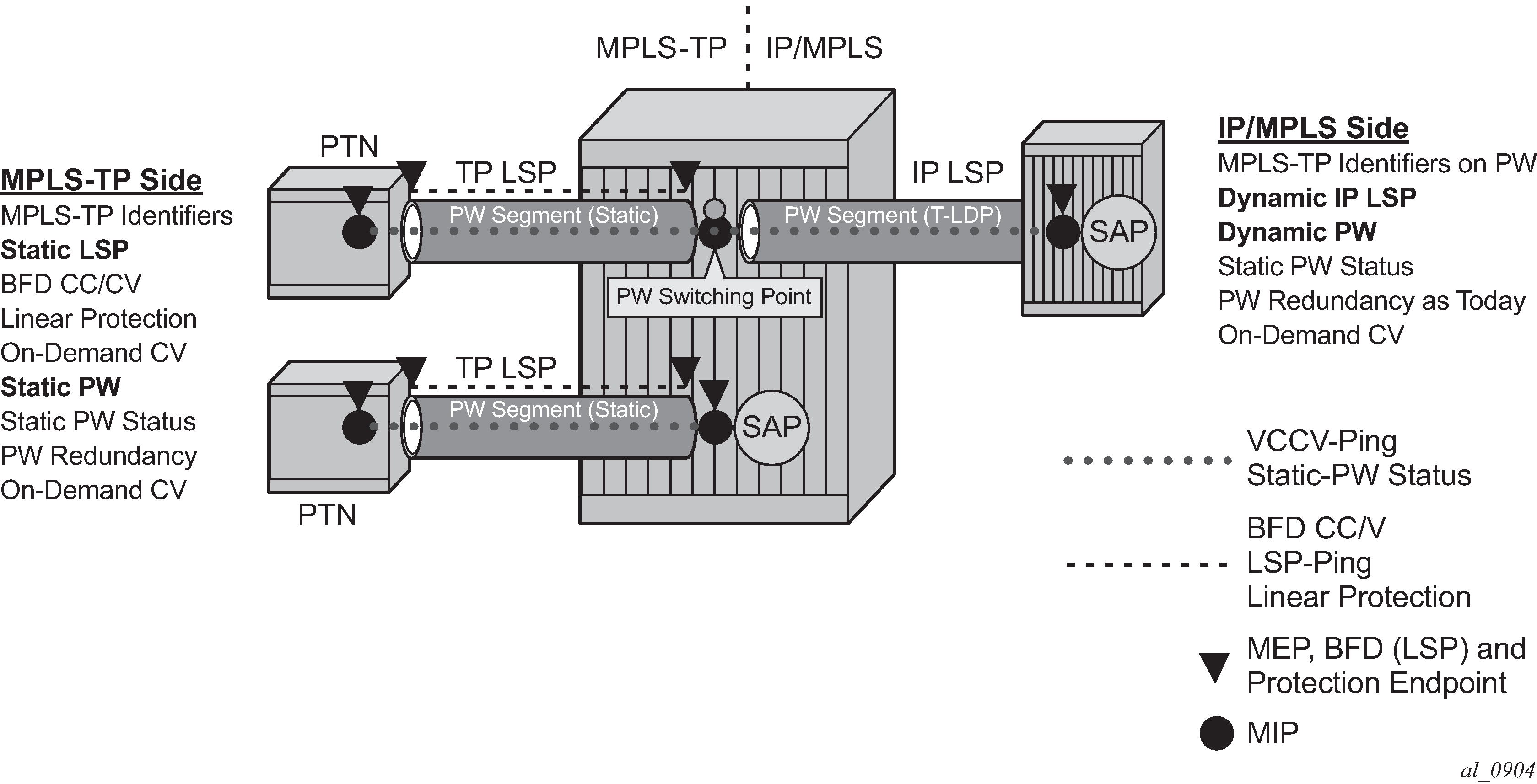
Services are backhauled from the static MPLS-TP network on the left to the dynamic IP/MPLS network on the right. The router acts as an S-PE interconnecting the static and dynamic domains.
The router implementation supports such use cases through the ability to mate a static MPLS-TP spoke SDP, with a defined pw-path-id, to a FEC128 spoke SDP. The dynamically signaled spoke SDP must be MPLS; GRE PWs are not supported, but the T-LDP signaled PW can use any supported MPLS tunnel type (for example, LDP, RSVP-TE, static, BGP). The control-word must be enabled on both mate spoke SDPs.
Mapping of control channel status signaling to and from T-LDP status signaling at the router S-PE is also supported.
The use of VCCV Ping and VCCV Trace on an MS-PW composed of a mix of static MPLS-TP and dynamic FEC128 segments is described in more detail in the 7450 ESS, 7750 SR, 7950 XRS, and VSR OAM and Diagnostics Guide.
VCCV BFD support for VLL, spoke-SDP termination on IES and VPRN, and VPLS services
This section provides information about VCCV Bidirectional Forwarding Detection (BFD) support for VLL, spoke-SDP termination on IES and VPRN, and VPLS services.
VCCV BFD support
The SR OS supports RFC 5885, which specifies a method for carrying BFD in a pseudowire-associated channel. This enables BFD to monitor the pseudowire between its terminating PEs, regardless of how many P routers or switching PEs the pseudowire may traverse. This makes it possible for faults that are local to individual pseudowires to be detected, whether they also affect forwarding for other pseudowires, LSPs, or IP packets. VCCV BFD is ideal for monitoring specific high-value services, where detecting forwarding failures (and potentially restoring from them) in the minimal amount of time is critical.
VCCV BFD is supported on VLL services using T-LDP spoke-SDPs or BGP VPWS. It is supported for Cpipe, Epipe, and Ipipe VLL services.
VCCV BFD is supported on IES/VPRN services with T-LDP spoke -SDP termination (for Epipes and Ipipes).
VCCV BFD is supported on LDP- and BGP-signaled pseudowires, and on pseudowires with statically configured labels, whether signaling is off or on for the SDP. VCCV BFD is not supported on MPLS-TP pseudowires.
VCCV BFD is supported on VPLS services (both spoke-SDPs and mesh SDPs). VCCV BFD is configured by:
-
configuring generic BFD session parameters in a BFD template
-
applying the BFD template to a spoke-SDP or pseudowire-template binding, using the bfd-template bfd-template-name command
-
enabling the template on that spoke-SDP, mesh SDP, or pseudowire-template binding using the bfd-enable command
VCCV BFD encapsulation on a pseudowire
The SR OS supports IP/UDP encapsulation for BFD. With this encapsulation type, the UDP headers are included on the BFD packet. IP/UDP encapsulation is supported for pseudowires that use router alert (VCCV Type 2), and for pseudowires with a control word (VCCV Type 1). In the control word case, the IPv4 channel (channel type 0x0021) is used. On the node, the destination IPv4 address is fixed at 127.0.0.1 and the source address is 127.0.0.2.
VCCV BFD sessions run end-to-end on a switched pseudowire. They do not terminate on an intermediate S-PE; therefore, the TTL of the pseudowire label on VCCV BFD packets is always set to 255 to ensure that the packets reach the far-end T-PE of an MS-PW.
BFD session operation
BFD packets flow along the full length of a PW, from T-PE to T-PE. Because they are not intercepted at an S-PE, single-hop initialization procedures are used.
A single BFD session exists per pseudowire.
BFD runs in asynchronous mode.
BFD operates as a simple connectivity check on a pseudowire. The BFD session state is displayed in the MIBs and in the show>service id>sdp>vccv-bfd session command. By default, BFD is not used to change the operational state of the pseudowire, to modify pseudowire redundancy, or to map the BFD state to SAP OAM. However, the router may be optionally configured to take into account the BFD session state.
VCCV BFD runs in software with a minimum supported timer interval of 100 ms for Epipe LDP spoke-SDP; H-VPLS spoke-SDP and mesh-SDP; and Epipe spoke-SDP termination on IES and VPRN interfaces, and inter-chassis backup spoke-SDPs.
BFD is used only for fault detection. While RFC 5885 provides a mode in which VCCV BFD can be used to signal pseudowire status, this mode is applicable only to pseudowires that have no other status signaling mechanism in use. LDP status and static pseudowire status signaling always take precedence over BFD-signaled PW status, and BFD-signaled pseudowire status is not used on pseudowires that use LDP status or static pseudowire status signaling mechanisms.
Using VCCV BFD to set SDP binding operational state
Use the failure-action down command to configure the router to use the VCCV BFD session state to affect the operational status of its SDP bindings (spoke-SDPs or mesh-SDPs). This behaviour is only supported for Epipe LDP spoke-SDPs, H-VPLS spoke-SDPs, inter-chassis backup spoke-SDPs, and Epipe spoke-SDP termination on IES and VPRN interfaces.
If this behavior is configured on a spoke-SDP bound to a VPLS or VPLS component of the R-VPLS, the SDP binding operational state is treated as an operationally down PW by the VPLS. This means that if all SDP bindings in the VPLS instance go operationally down because the VCCV BFD is going down, the VPLS goes down. In the case of R-VPLS, this handling is required to take down the associated IP interface if all SDP bindings are down. An operational down state that is caused by the BFD session going down removes the SDP binding from the eligible set used for PW redundancy in a VPLS or VLL service, including spoke SDP termination on IES or VPRN interfaces.
An operational down state of the SDP binding, because the VCCV BFD session is going down, is mapped to any SAP OAM mechanisms. It also contributes to the operational state of an operational group that is monitoring the SDP binding on which VCCV BFD with failure-action down is configured.
Configuring VCCV BFD
Generic BFD session parameters are configured for VCCV using the bfd-template command, in the config>router>bfd context. However, there are some restrictions.
For VCCV, the BFD session cannot terminate on the CPM network processor. Therefore, an error is generated if the user tries to bind a BFD template using the type cpm-np command within the config>router>bfd>bfd-template context.
Attempting to bind a BFD template with any unsupported transmit or receive interval generates an error.
Finally, attempting to commit changes to a BFD template that is already bound to a PW where the new values are invalid for VCCV BFD results in an error.
If the preceding BFD timer values are changed in a specified template, any BFD sessions on PWs to which that template is bound try to renegotiate their timers to the new values.
Commands within the BFD-template use a begin-commit model. To edit any value within the BFD template, a begin command needs to be executed after the template context has been entered. However, a value is still stored temporarily in the template-module until the commit command is issued. When the commit is issued, values are used by other modules such as the MPLS-TP module and BFD module.
For PWs where the PW template does not apply, a named BFD template is configured on the spoke-SDP using the config service [epipe | cpipe | apipe | fpipe | ipipe] spoke-sdp bfd bfd-template command and then enabled using the config service [epipe | cpipe | apipe | fpipe | ipipe] spoke-sdp bfd bfd-enable command. For example, LDP-signaled spoke-SDPs for a VLL service that uses the PW ID FEC (FEC128) or spoke-SDPs with static PW labels.
Configuring and enabling a BFD template on a static PW already configured with MPLS-TP identifiers (that is, with a pw-path-id) or on a spoke-SDP with a configured pw-path-id is not supported. Likewise, if a BFD template is configured and enabled on a spoke-SDP, a pw-path-id cannot be configured on the spoke-SDP.
The bfd-enable command is blocked on a spoke-SDP configured with VC-switching. This is because VCCV BFD always operates end-to-end on an MS-pseudowire. It is not possible to extract VCCV BFD packets at the S-PE.
For IES and VPRN spoke-SDP termination where the PW template does not apply (that is, where the spoke-SDP is signaled with LDP and uses the PW ID FEC (FEC128)), the BFD template is configured using the config service ies | vprn if spoke-sdp bfd bfd-template command, then enabled using the config service ies | vprn if spoke-sdp bfd bfd-enable command.
For H-VPLS, where the PW template does not apply (that is, LDP-VPLS spoke SDPs that use the PW ID FEC(FEC128)) the BFD template is configured using the configure service vpls spoke-sdp bfd bfd-template or the configure service vpls mesh-sdp bfd bfd-template command. VCCV BFD is then enabled with the bfd-enable command under the vpls spoke-sdp bfd or vpls mesh-sdp bfd context.
PWs where the PW template does apply and that support VCCV BFD are as follows:
BGP-AD, which is signaled using the Generalized PW ID FEC (FEC129) with Attachment Individual Identifier (AII) type I
BGP VPLS
BGP VPWS
For these PW types, a named BFD template is configured and enabled from the PW template binding context.
For BGP VPWS, the BFD template is configured using the config service epipe bgp pw-template-binding bfd-template name command, then enabled using the config service epipe bgp pw-template-binding bfd-enable command.
The ability to determine PW forwarding state from VCCV BFD on the pseudowire is configured using the failure-action down command. It is possible to configure failure-action whether a spoke-SDP is administratively shutdown or not. It is therefore recommended to first configure VCCV BFD to ensure the spoke-SDP is forwarding, and then configure the failure-action command. If the failure-action down command is configured, the router continues to send VCCV BFD packets on a spoke-SDP or mesh-SDP that is operationally down because of the VCCV BFD session being in the down state. The router can then rapidly detect when connectivity is restored.
The wait-for-up-timer can be configured when failure-action down is configured. The wait-for-up-timer timer is triggered when a spoke-SDP or mesh-SDP is first administratively enabled and when a VCCV BFD session transitions from up to down. It is useful to allow time for BFD sessions to come up when the spoke-SDP is initially no shutdown. This provides the BFD session time to settle before it selects the active spoke-SDP for use in a redundant set. It also prevents excessive flapping of the operation state of a spoke-SDP if a VCCV BFD session is bouncing.
Pseudowire switching
The pseudowire switching feature provides the user with the ability to create a VLL service by cross-connecting two spoke-SDPs. This feature allows the scaling of VLL and VPLS services in a large network in which the otherwise full mesh of PE devices would require thousands of Targeted LDP (T-LDP) sessions per PE node.
Services with one SAP and one spoke-SDP are created normally on the PE; however, the target destination of the SDP is the pseudowire switching node instead of what is normally the remote PE. Also, the user configures a VLL service on the pseudowire switching node using the two SDPs.
The pseudowire switching node acts in a passive role with respect to signaling of the pseudowires. It waits until one or both of the PEs sends the label mapping message before relaying it to the other PE. This is because it needs to pass the interface parameters of each PE to the other.
A pseudowire switching point TLV is inserted by the switching pseudowire to record its system address when relaying the label mapping message. This TLV is useful in a few situations:
It allows for troubleshooting of the path of the pseudowire especially if multiple pseudowire switching points exist between the two PEs.
It helps in loop detection of the T-LDP signaling messages where a switching point would receive back a label mapping message it had already relayed.
The switching point TLV is inserted in pseudowire status notification messages when they are sent end-to-end or from a pseudowire switching node toward a destination PE.
In the following example, the user configures a regular Epipe VLL service PE1 and PE2. These services each consist of a SAP and a spoke-SDP. However, the target destination of the SDP is not the remote PE, but the pseudowire switching node. Also, the user configures an Epipe VLL service on the pseudowire switching node using the two SDPs.
|7450 ESS, 7750 SR, and 7950 XRS PE1 (Epipe)|---sdp 2:10---|7450 ESS, 7750 SR, and
7950 XRS PW SW (Epipe)|---sdp 7:15---|7450 ESS, 7750 SR, and 7950 XRS PE2 (Epipe)|
Configuration examples are in Configuring two VLL paths terminating on T-PE2.
Pseudowire switching with protection
Pseudowire switching scales VLL and VPLS services over a multi-area network by removing the need for a full mesh of targeted LDP sessions between PE nodes. VLL resilience with pseudowire redundancy and switching shows the use of pseudowire redundancy to provide a scalable and resilient VLL service across multiple IGP areas in a provider network.
In the network in VLL resilience with pseudowire redundancy and switching, PE nodes act as leading nodes, and pseudowire switching nodes act as followers for the purpose of pseudowire signaling. A switching node needs to pass the SAP interface parameters of each PE to the other PEs. T-PE1 sends a label mapping message for the Layer 2 FEC to the peer pseudowire switching node; for example, S-PE1. The label mapping message includes the SAP interface parameters, such as MTU, in the label mapping message. S-PE1 checks the FEC against the local information and, if a match exists, appends the optional pseudowire switching point TLV to the FEC TLV in which it records its system address. T-PE1 then relays the label mapping message to S-PE2. S-PE2 performs similar operations and forwards a label mapping message to T-PE2.
The same procedures are followed for the label mapping message in the reverse direction; for example, from T-PE2 to T-PE1. S-PE1 and S-PE2 make the spoke-SDP cross-connect only when both directions of the pseudowire are signaled and matched.
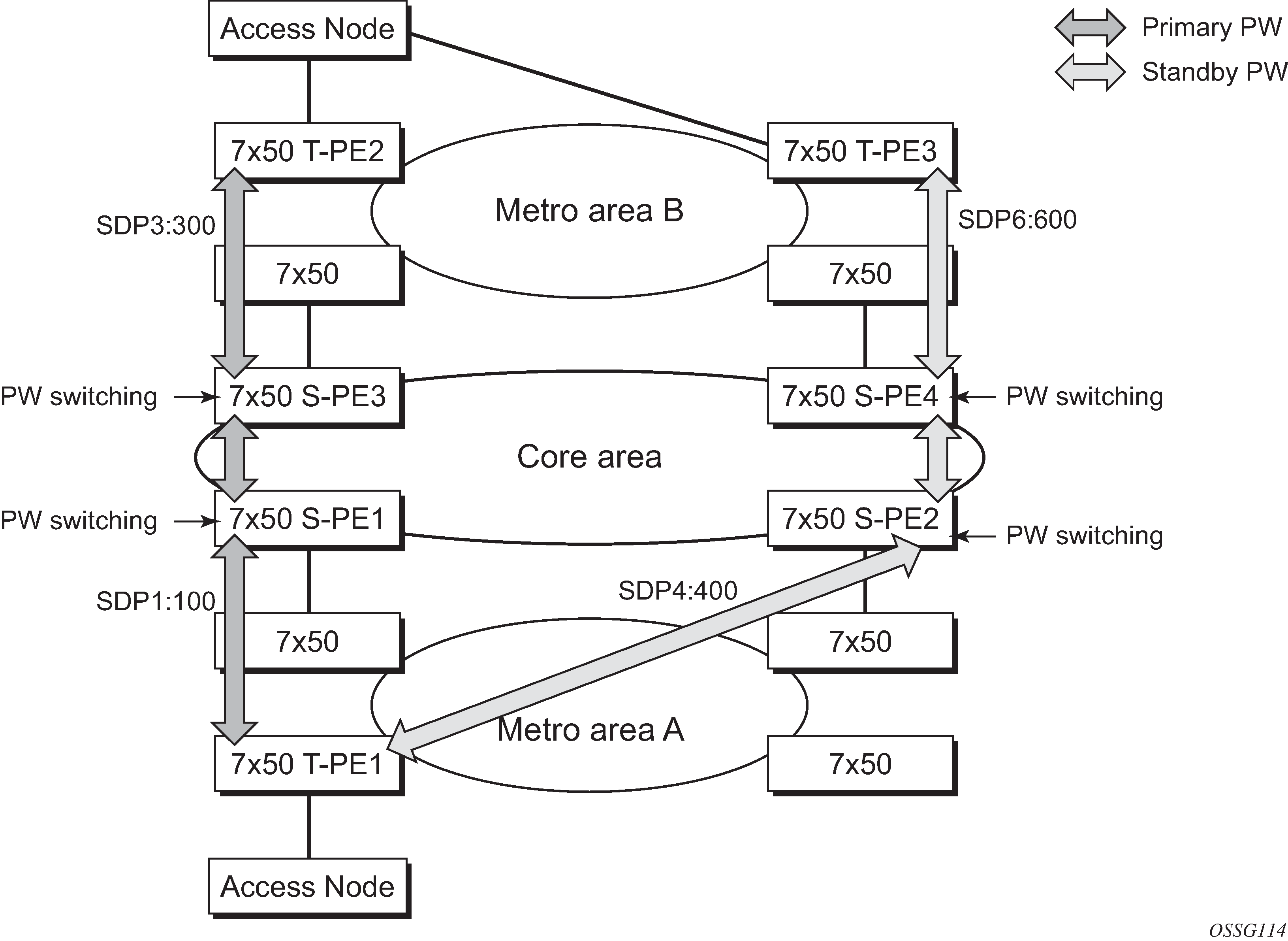
The pseudowire switching TLV is useful in a few situations. First, it allows for troubleshooting of the path of the pseudowire, especially if multiple pseudowire switching points exist between the two T-PE nodes. Second, it helps in loop detection of the T-LDP signaling messages where a switching point receives back a label mapping message that the point already relayed. Finally, it can be inserted in pseudowire status messages when they are sent from a pseudowire switching node toward a destination PE.
Pseudowire status messages can be generated by the T-PE nodes and, or the S-PE nodes. Pseudowire status messages received by a switching node are processed and passed on to the next hop. An S-PE node appends the optional pseudowire switching TLV, with the S-PEs system address added to it, to the FEC in the pseudowire status notification message, only if that S-PE originated the message or the message was received with the TLV in it. Otherwise, the message was originated by a T-PE node and the S-PE should process and pass the message without changes, except for the VC-ID value in the FEC TLV.
Pseudowire switching behavior
In the network in VLL resilience with pseudowire redundancy and switching, PE nodes act as leading nodes and pseudowire switching nodes act as followers for the purpose of pseudowire signaling. This is because a switching node needs to pass the SAP interface parameters of each PE to the other. T-PE1 sends a label mapping message for the Layer 2 FEC to the peer pseudowire switching node; for example, S-PE1. It includes the SAP interface parameters, such as MTU, in the label mapping message. S-PE1 checks the FEC against the local information and, if a match exists, appends the optional pseudowire switching point TLV to the FEC TLV in which it records its system address. T-PE1 then relays the label mapping message to S-PE2. S-PE2 performs similar operation and forwards a label mapping message to T-PE2.
The same procedures are followed for the label mapping message in the reverse direction; for example, from T-PE2 to T-PE1. S-PE1 and S-PE2 affect the spoke-SDP cross-connect only when both directions of the pseudowire are signaled and matched.
Pseudowire status messages can be generated by the T-PE nodes and, or the S-PE nodes. Pseudowire status messages received by a switching node are processed, then passed on to the next hop. An S-PE node appends the optional pseudowire switching TLV, with its system address added to it, to the FEC in the pseudowire status notification message, only if it originated the message or the message was received with the TLV in it. Otherwise, the message was originated by a T-PE node and the S-PE should process and pass the message without changes, except for the VC-ID value in the FEC TLV.
The merging of the received T-LDP status notification message and the local status for the spoke-SDPs from the service manager at a PE complies with the following rules:
When the local status for both spoke-SDPs is up, the S-PE passes any received SAP or SDP binding generated status notification message unchanged; for example, the status notification TLV is unchanged but the VC-ID in the FEC TLV is set to value of the pseudowire segment to the next hop.
When the local operational status for any of the spokes is down, the S-PE always sends an SDP-binding down status bits regardless of whether the received status bits from the remote node indicated SAP up or down or SDP-binding up or down.
Pseudowire switching TLV
The format of the pseudowire switching TLV is as follows.

- PW sw TLV Length
- specifies the total length of all the following pseudowire switching point TLV fields in octets
- Type
- encodes how the Value field is to be interpreted
- Length
- specifies the length of the Value field in octets
- Value
- octet string of Length octets that encodes information to be interpreted as specified by the Type field
Pseudowire switching point sub-TLVs
Following is information specific to pseudowire switching point sub-TLVs:
pseudowire ID of last pseudowire segment traversed
This is the sub-TLV type that contains a pseudowire ID in the format of the pseudowire ID.
pseudowire switching point description string
This is an optional description text string of up to 80 characters.
IP address of pseudowire switching point
This is an options sub-TLV; IP V4 or V6 address of the pseudowire switching point.
MH VCCV capability indication
Static-to-dynamic pseudowire switching
When one segment of the pseudowire cross-connect at the S-PE is static while the other is signaled using T-LDP, the S-PE operates much like a T-PE from a signaling perspective and as an S-PE from a data plane perspective.
The S-PE signals a label mapping message as soon as the local configuration is complete. The control word C-bit field in the pseudowire FEC is set to the value configured on the static spoke-SDP.
When the label mapping for the egress direction is also received from the T-LDP peer, and the information in the FEC matches that of the local configuration, the static-to-dynamic cross-connect is created.
It is possible that end nodes of a static pseudowire segment can be misconfigured. In this case, an S-PE or T-PE node may be receiving packets with the wrong encapsulation, so that an invalid payload could be forwarded over the pseudowire or the SAP, respectively. Also, if the S-PE or T-PE node is expecting the control word in the packet encapsulation and the received packet comes with no control word, but the first nibble below the label stack is 0x0001, the packet may be mistaken for a VCCV OAM packet and may be forwarded to the CPM. In that case, the CPM performs a check of the IP header fields such as version, IP header length, and checksum. If any of these fail the VCCV packet is discarded.
Ingress VLAN swapping
This feature is supported on VPLS and VLL services where the end-to-end solution is built using two node solutions (requiring SDP connections between the nodes).
In VLAN swapping, only the VLAN ID value is copied to the inner VLAN position. The Ethertype of the inner tag is preserved and all consecutive nodes work with that value. Similarly, the dot1p bits value of outer tag is not preserved.
Ingress VLAN swapping shows a network where, at user-access side (DSLAM-facing SAPs), every subscriber is represented by several QinQ SAPs with inner-tag encoding service and outer tag encoding subscriber (DSL line). At the aggregation side (BRAS- or PE-facing SAPs) every subscriber is represented by DSL line number (inner VLAN tag) and DSLAM (outer VLAN tag). The effective operation on the VLAN tag is to drop the inner tag at the access side and push another tag at the aggregation side.
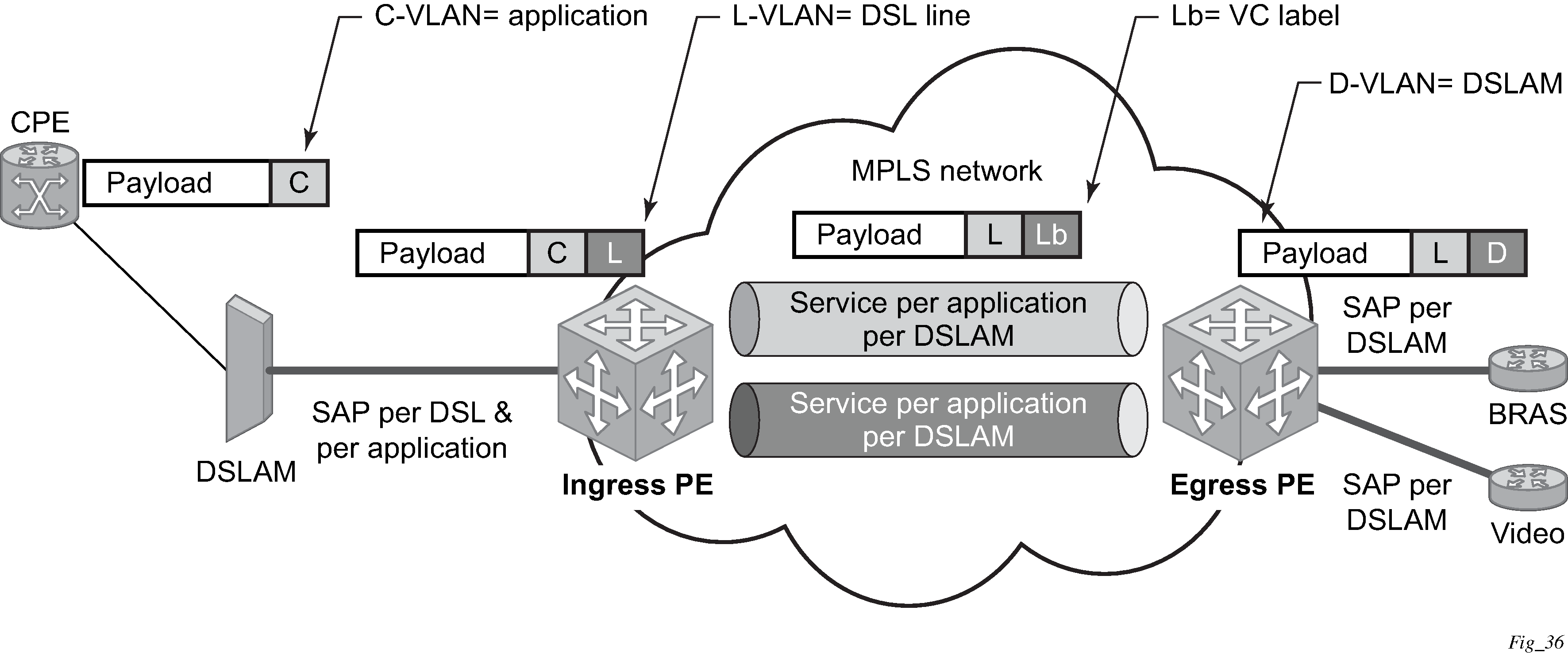
Ingress VLAN translation
Ingress VLAN translation shows an application where different circuits are aggregated in the VPLS-based network. The access side is represented by an explicit do1q encapsulated SAP. Because the VLAN ID is port specific, those connected to different ports may have the same VLAN. The aggregation side is aggregated on the same port; therefore, a unique VLAN ID is required.
Pseudowire redundancy
Pseudowire redundancy provides the ability to protect a pseudowire with a pre-provisioned secondary standby pseudowire and to switch traffic over to that secondary standby pseudowire in case of a SAP and, or network failure condition. Normally, pseudowires are redundant by the virtue of the SDP redundancy mechanism. For instance, if the SDP is an RSVP LSP and is protected by a secondary standby path and, or by Fast-Reroute paths (FRR), the pseudowire is also protected. However, there are two applications in which SDP redundancy does not protect the end-to-end pseudowire path:
There are two different destination PE nodes for the same VLL service. The main use case is the provision of dual-homing of a CPE or access node to two PE nodes located in different POPs. The other use case is the provision of a pair of active and standby BRAS nodes, or active and standby links to the same BRAS node, to provide service resiliency to broadband service subscribers.
The pseudowire path is switched in the middle of the network and the pseudowire switching node fails.
Pseudowire and VPLS link redundancy extends link-level resiliency for pseudowires and VPLS to protect critical network paths against physical link or node failures. These innovations enable the virtualization of redundant paths across the metro or core IP network to provide seamless and transparent fail-over for point-to-point and multi-point connections and services. When deployed with multi-chassis LAG, the path for return traffic is maintained through the pseudowire or VPLS switchover, which enables carriers to deliver ‟always on” services across their IP/MPLS networks.
Dynamic multi-segment pseudowire routing
Overview
Dynamic Multi-Segment Pseudowire Routing (Dynamic MS-PWs) enable a complete multi-segment pseudowire to be established, while only requiring per-pseudowire configuration on the T-PEs. No per-pseudowire configuration is required on the S-PEs. End-to-end signaling of the MS-PW is achieved using T-LDP, while multi-protocol BGP is used to advertise the T-PEs, allowing dynamic routing of the MS-PW through the intervening network of S-PEs. Dynamic multi-segment pseudowires are described in the IETF Draft draft-ietf-pwe3-dynamic-ms-pw-13.txt.
Dynamic MS-PW overview shows the operation of dynamic MS-PWs.
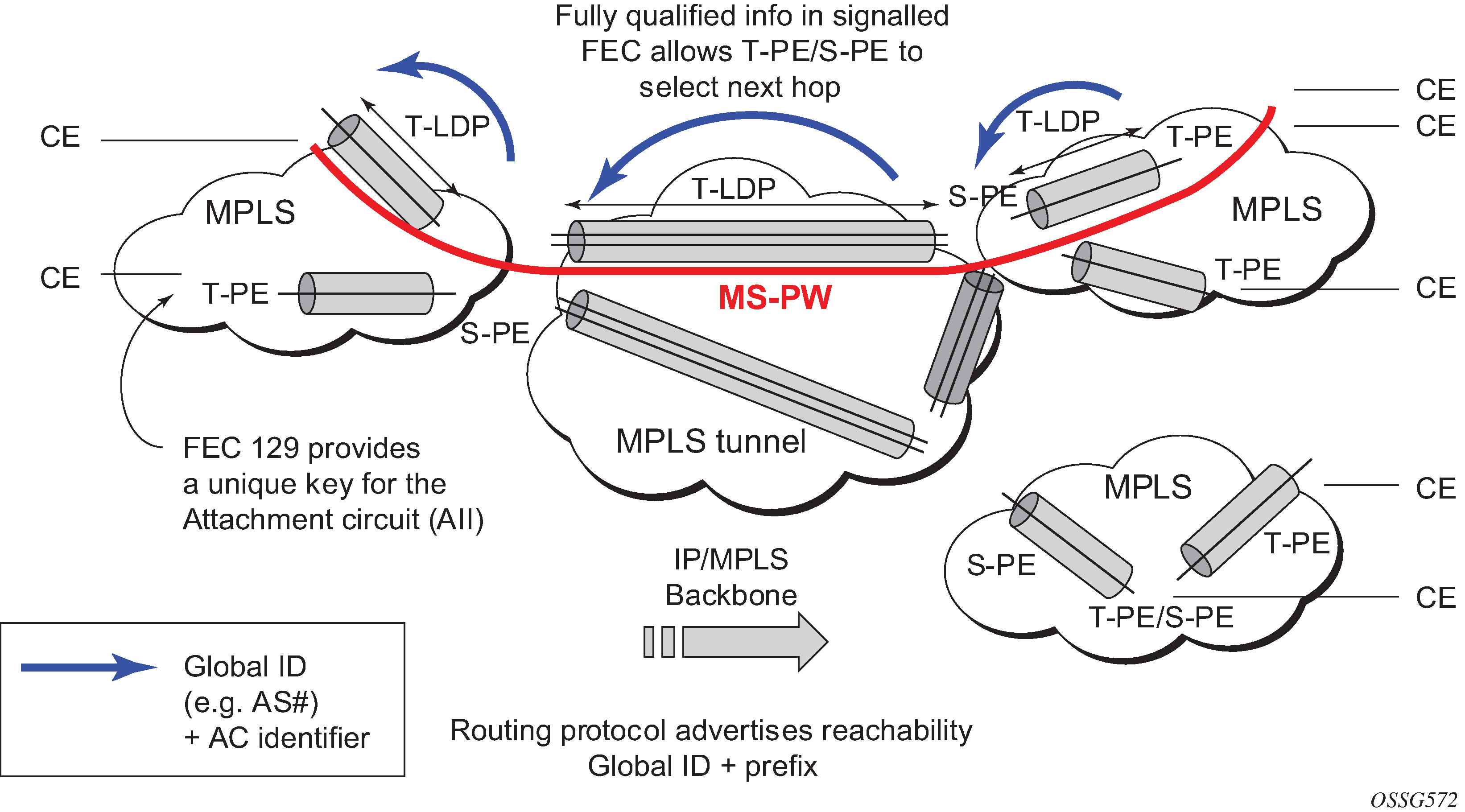
The FEC 129 AII Type 2 structure depicted in MS-PW addressing using FEC129 AII Type 2 is used to identify each individual pseudowire endpoint:

A 4-byte global-id followed by a 4-byte prefix and a 4-byte attachment circuit ID are used to provide for hierarchical, independent allocation of addresses on a per-service provider network basis. The first 8 bytes (global-id + prefix) may be used to identify each individual T-PE or S-PE as a loopback Layer 2 address.
The AII type is mapped into the MS-PW BGP NLRI (a BGP AFI of L2VPN, and SAFI for network layer reachability information for dynamic MS-PWs). As soon as a new T- PE is configured with a local prefix address of global id: prefix, pseudowire routing proceeds to advertise this new address to all the other T- PEs and S-PEs in the network, as depicted in Advertisement of PE addresses by PW routing.
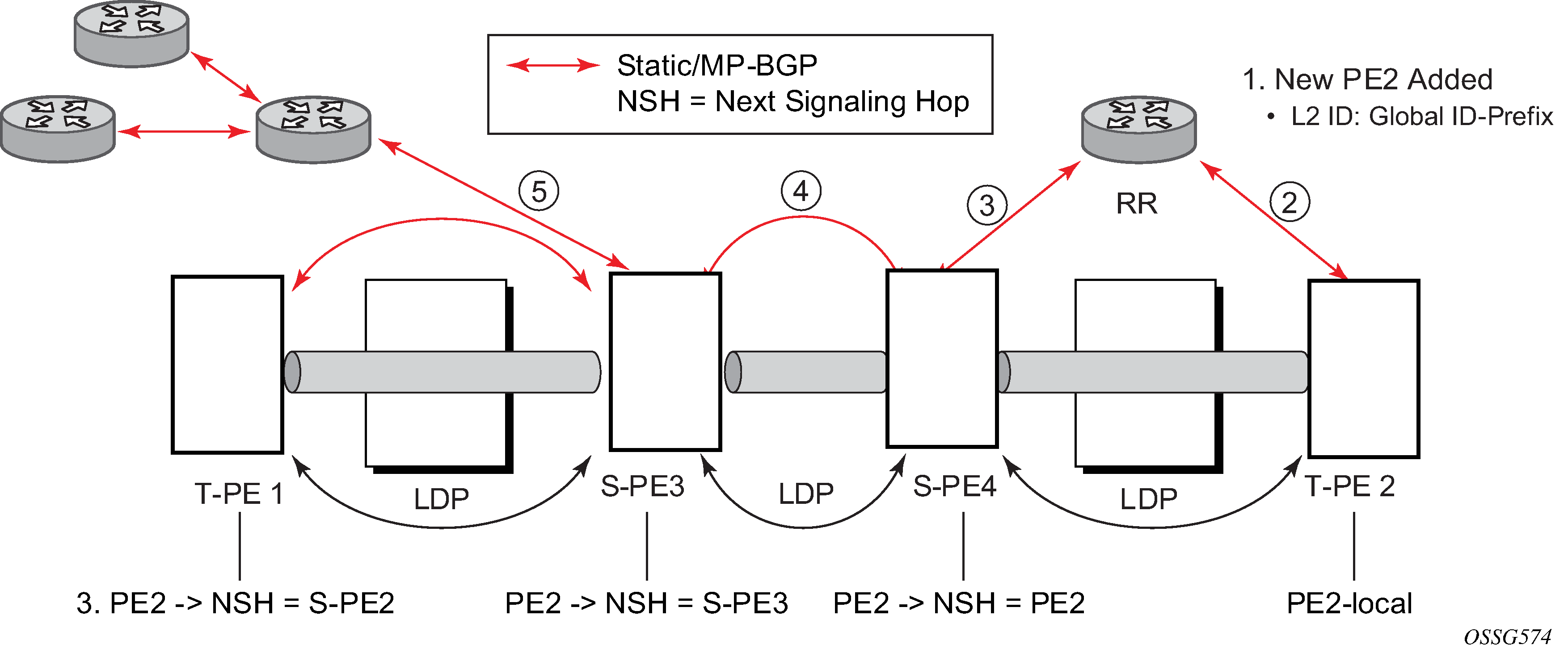
In step 1 of Advertisement of PE addresses by PW routing, a new T-PE (T-PE2) is configured with a local prefix.
Next, in steps 2 to 5, MP-BGP uses the NLRI for the MS-PW routing SAFI to advertise the location of the new T-PE to all the other PEs in the network. Alternatively, static routes may be configured on a per T-PE/S-PE basis to accommodate non-BGP PEs in the solution.
As a result, pseudowire routing tables for all the S-PEs and remote T-PEs are populated with the next hop to be used to reach T-PE2.
VLL services can then be established, as illustrated in Signaling of dynamic MS-PWs using T-LDP.

In step 1 and 1' of Signaling of dynamic MS-PWs using T-LDP the T-PEs are configured with the local and remote endpoint information: source AII (SAII) and Target AII (TAII). On the router, the AIIs are locally configured for each spoke-SDP, according to the model shown in Mapping of AII to SAP. Therefore the router provides for a flexible mapping of the AII to SAP. That is, the values used for the AII are through local configuration, and it is the context of the spoke-SDP that binds it to a specific SAP.
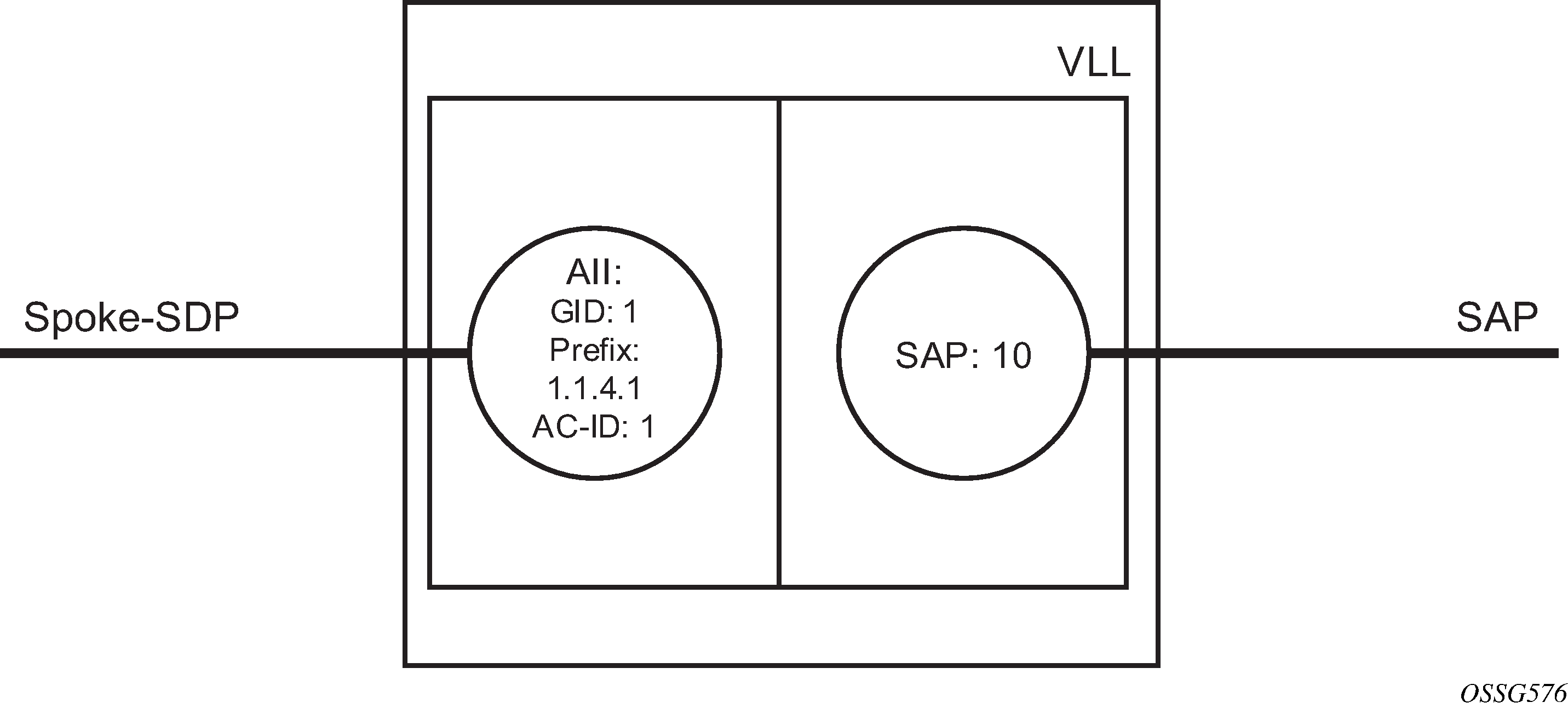
Before T-LDP signaling starts, the two T-PEs decide on an active and passive relationship using the highest AII (comparing the configured SAII and TAII) or the configured precedence. Next, the active T-PE (in the IETF draft, this is referred to as the source T-PE or ST-PE) checks the PW routing table to determine the next signaling hop for the configured TAII using the longest match between the TAII and the entries in the PW routing table.
This signaling hop is then used to choose the T-LDP session to the chosen next-hop S-PE. Signaling proceeds through each subsequent S-PE using similar matching procedures to determine the next signaling hop. Otherwise, if a subsequent S-PE does not support dynamic MS-PW routing, so uses a statically configured PW segment, the signaling of individual segments follows the procedures already implemented in the PW Switching feature.
BGP can install a PW AII route in the PW routing table with ECMP next-hops. However, when LDP needs to signal a PW with matching TAII, it chooses only one next-hop from the available ECMP next-hops. PW routing supports up to 4 ECMP paths for each destination.
The signaling of the forward path ends when the PE matches the TAII in the label mapping message with the SAII of a spoke-SDP bound to a local SAP. The signaling in the reverse direction can now be initiated, which follows the entries installed in the forward path. The PW routing tables are not consulted for the reverse path. This ensures that the reverse direction of the PW follows exactly the same set of S-PEs as the forward direction.
This solution can be used in either a MAN-WAN environment or in an Inter-AS/Inter-Provider environment as depicted in VLL using dynamic MS-PWs, inter-AS scenario.

Data plane forwarding at the S-PEs uses pseudowire service label switching, as per the pseudowire switching feature.
Pseudowire routing
Each S-PE and T-PE has a pseudowire routing table that contains a reference to the T-LDP session to use to signal to a set of next hop S-PEs to reach a specific T-PE (or the T-PE if that is the next hop). For VLLs, this table contains aggregated AII Type 2 FECs and may be populated with routes that are learned through MP-BGP or that are statically configured.
MP-BGP is used to automatically distribute T-PE prefixes using the new MS-PW NLRI, or static routes can be used. The MS-PW NLRI is composed of a Length, an 8-byte route distinguisher (RD), a 4-byte global-id, a 4-byte local prefix, and (optionally) a 4-byte AC-ID. Support for the MS-PW address family is configured in CLI under the config>router>bgp>family ms-pw context.
MS-PW routing parameters are configured in the config>service>pw-routing context.
To enable support for dynamic MS-PWs on a 7750 SR, 7450 ESS, or 7950 XRS node to be used as a T-PE or S-PE, a single, globally unique, S-PE ID, known as the S-PE address, is first configured under config>service>pw-routing on each node to be used as a T-PE or S-PE. The S-PE address has the format global-id:prefix. It is not possible to configure any local prefixes used for pseudowire routing or to configure spoke-SDPs using dynamic MS-PWs at a T-PE unless an S-PE address has already been configured. The S-PE address is used as the address of a node used to populate the switching point TLV in the LDP label mapping message and the pseudowire status notification sent for faults at an S-PE.
Each T-PE is also configured with the following parameters:
global-id
This is a 4-byte identifier that uniquely identifies an operator or the local network.
-
local prefix
One or more local (Layer 2) prefixes (up to a maximum of 16), which are formatted in the style of a 4-octet IPv4 address. A local prefix identifies a T-PE or S-PE in the PW routing domain.
For each local prefix, at least one 8-byte RD can be configured. It is also possible to configure an optional BGP community attribute.
For each local prefix, BGP then advertises each global-id/prefix tuple and unique RD and community pseudowire using the MS-PW NLRI, based on the aggregated FEC129 AII Type 2 and the Layer 2 VPN/PW routing AFI/SAFI 25/6, to each T-PE/S-PE that is a T-LDP neighbor, subject to local BGP policies.
The dynamic advertisement of each of these pseudowire routes is enabled for each prefix and RD using the advertise-bgp command.
An export policy is also required to export MS-PW routes in MP-BGP. This can be done using a default policy, such as the following:
*A:lin-123>config>router>policy-options# info
----------------------------------------------
            policy-statement "ms-pw"
                default-action accept
                exit
            exit
----------------------------------------------
However, this would export all routes. A recommended choice is to enable filtering per-family, as follows:
*A:lin-123>config>router>policy-options# info
----------------------------------------------
            policy-statement "to-mspw"
                entry 1
                    from
                        family ms-pw
                    exit
                    action accept
                    exit
                exit
            exit
----------------------------------------------
The following command is then added in the config>router>bgp context:
export "to-mspw"
Local-preference for IBGP and BGP communities can be configured under such a policy.
Static routing
As well as support for BGP routing, static MS-PW routes may also be configured using the config services pw-routing static-route command. Each static route comprises the target T-PE global-id and prefix, and the IP address of the T-LDP session to the next hop S-PE or T-PE that should be used.
If a static route is set to 0, this represents the default route. If a static route exists to a specified T-PE, this default route is used in preference to any BGP route that may exist.
Explicit paths
A set of default explicit routes to a remote T-PE or S-PE prefix may be configured on a T-PE under config>services>pw-routing using the path name command. Explicit paths are used to populate the explicit route TLV used by MS-PW T-LDP signaling. Only strict (fully qualified) explicit paths are supported.
It is possible to configure explicit paths independently of the configuration of BGP or static routing.
Configuring VLLs using dynamic MS-PWs
One or more spoke-SDPs may be configured for distributed Epipe VLL services. Dynamic MS-PWs use FEC129 (also known as the Generalized ID FEC) with Attachment Individual Identifier (AII) Type 2 to identify the pseudowire, as opposed to FEC128 (also known as the PW ID FEC) used for traditional single segment pseudowires and for pseudowire switching. FEC129 spoke-SDPs are configured under the spoke-sdp-fec command.
FEC129 AII Type 2 uses a Source Attachment Individual Identifier (SAII) and a Target Attachment Individual Identifier (TAII) to identify the end of a pseudowire at the T-PE. The SAII identifies the local end, while the TAII identifies the remote end. The SAII and TAII are each structured as follows:
global-id
This is a 4-byte identifier that uniquely identifies an operator or the local network.
prefix
This is a 4-byte prefix, which should correspond to one of the local prefixes assigned under pw-routing.
AC-ID
This is a 4-byte identifier for the local end of the pseudowire. This should be locally unique within the scope of the global-id:prefix.
Active/passive T-PE selection
Dynamic MS-PWs use single-sided signaling procedures with double-sided configuration; a fully qualified FEC must be configured at both endpoints. That is, one T-PE (the source T-PE, ST-PE) of the MS-PW initiates signaling for the MS-PW, while the other end (the terminating T-PE, TT-PE) passively waits for the label mapping message from the far end. This termination end only responds with a label mapping message to set up the opposite direction of the MS-PW when it receives the label mapping from the ST-PE. By default, the router determines which T-PE is the ST-PE (the active T-PE) and which is the TT-PE (the passive T-PE) automatically, based on comparing the SAII with the TAII as unsigned integers. The T-PE with SAII>TAII assumes the active role. However, it is possible to override this behavior using the signaling {master | auto} command under spoke-sdp-fec. If master is selected at a specified T-PE, that T-PE assumes the active role. If a T-PE is at the endpoint of a spoke-SDP that is bound to an VLL SAP and single-sided auto-configuration is used, then that endpoint is always passive. For more information, see Automatic endpoint configuration. Therefore, signaling master should only be used when it is known that the far end assumes a passive behavior.
Automatic endpoint configuration
Automatic endpoint configuration allows the configuration of an endpoint without specifying the TAII associated with that spoke-sdp-fec. It allows a single-sided provisioning model where an incoming label mapping message with a TAII that matches the SAII of that spoke-SDP is automatically bound to that endpoint. This is useful in scenarios where a service provider wants to separate service configuration from the service activation phase.
Automatic endpoint configuration is supported for Epipe VLL spoke-sdp-fec endpoints bound to a VLL SAP. It is configured using the spoke-sdp-fec auto-config command, and excluding the TAII from the configuration. When auto-configuration is used, the node assumes passive behavior from a point of view of T-LDP signaling. See Active/passive T-PE selection for more information. Therefore, the far-end T-PE must be configured as the signaling master for that spoke-sdp-fec.
Selecting a path for an MS-PW
Path selection for signaling occurs in the outbound direction (ST-PE to TT-PE) for an MS-PW. In the TT-PE to ST-PE direction, a label mapping message follows the reverse of the path already taken by the outgoing label mapping.
A node can use explicit paths, static routes, or BGP routes to select the next hop S-PE or T-PE. The order of preference used in selecting these routes is:
Explicit Path
Static route
BGP route
To use an explicit path for an MS-PW, an explicit path must have been configured in the config>services>pw-routing>path path-name context. The user must then configure the corresponding path path-name under spoke-sdp-fec.
If an explicit path name is not configured, the TT-PE or S-PE performs a longest match lookup for a route (static if it exists, and BGP if not) to the next hop S-PE or T-PE to reach the TAII.
Pseudowire routing chooses the MS-PW path in terms of the sequence of S-PEs to use to reach a specified T-PE. It does not select the SDP to use on each hop, which is instead determined at signaling time. When a label mapping is sent for a specified pseudowire segment, an LDP SDP is used to reach the next-hop S-PE/T-PE if such an SDP exists. If not, and an RFC 8277 labeled BGP SDP is available, then that is used. Otherwise, the label mapping fails and a label release is sent.
Pseudowire templates
Dynamic MS-PWs support the use of the pseudowire template for specifying generic pseudowire parameters at the T-PE. The pseudowire template to use is configured in the spoke-sdp-fec>pw-template-bind policy-id context. Dynamic MS-PWs do not support the provisioned SDPs specified in the pseudowire template. Auto-created GRE SDPs are supported with dynamic MS-PWs by creating the PW template used within the spoke-sdp-fec with the parameter auto-gre-sdp.
Pseudowire redundancy
Pseudowire redundancy is supported on dynamic MS-PWs used for VLLs. It is configured in a similar manner to pseudowire redundancy on VLLs using FEC128, whereby each spoke-sdp-fec within an endpoint is configured with a unique SAII/TAII.
Pseudowire redundancy shows the use of pseudowire redundancy.
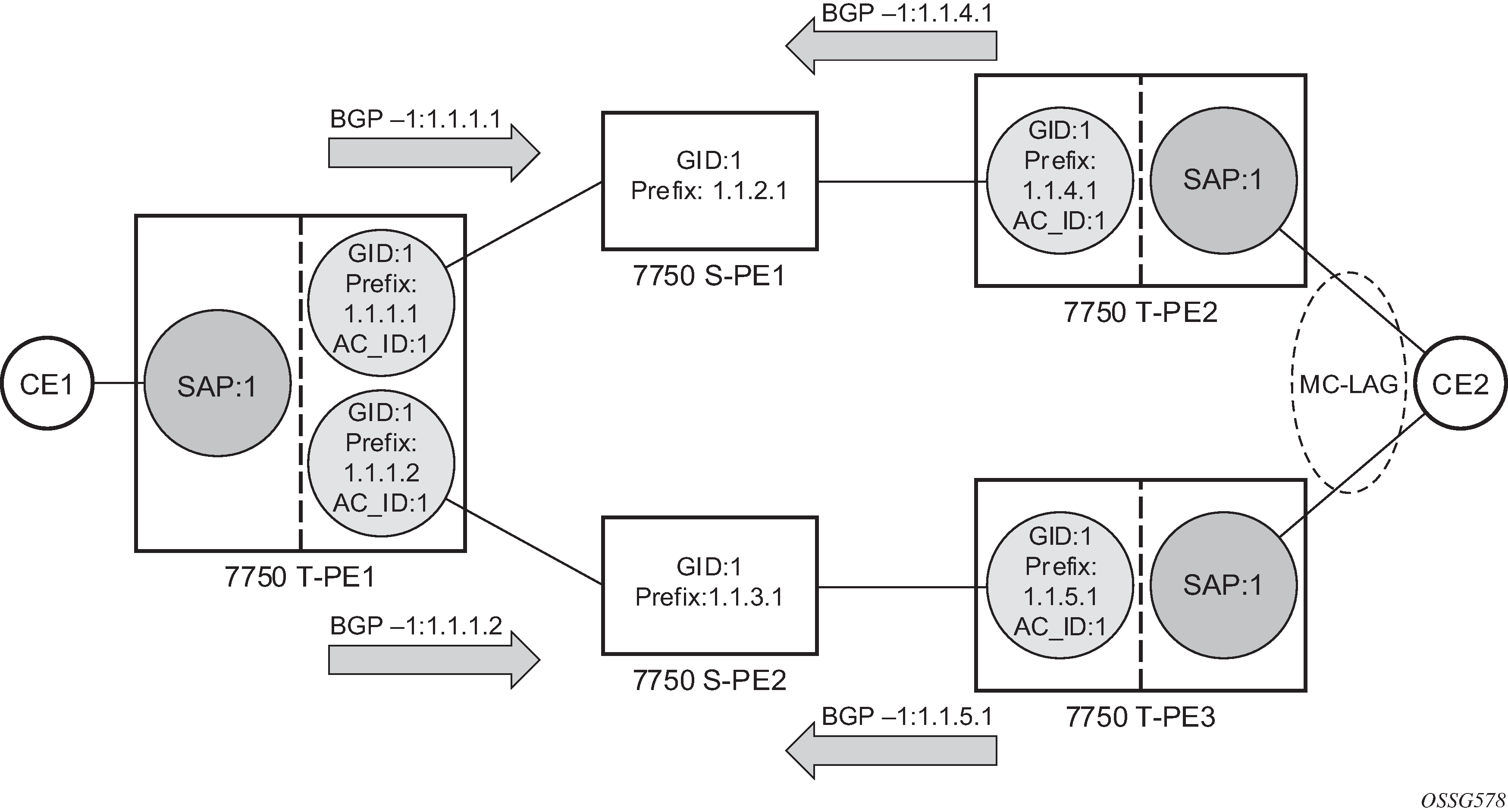
The following is a summary of the key points to consider in using pseudowire redundancy with dynamic MS-PWs:
Each MS-PW in the redundant set must have a unique SAII/TAII set and is signaled separately. The primary pseudowire is configured in the spoke-sdp-fec>primary context.
Each MS-PW in the redundant set should use a diverse path (from the point of view of the S-PEs traversed) from every other MS-PW in that set if path diversity is possible in a specific network topology. There are a number of possible ways to achieve this:
Configure an explicit path for each MS-PW.
Allow BGP routing to automatically determine diverse paths using BGP policies applied to different local prefixes assigned to the primary and standby MS-PWs.
Path diversity can be further provided for each primary pseudowire through the use of a BGP RD.
If the primary MS-PW fails, fail-over to a standby MS-PW occurs, as per the normal pseudowire redundancy procedures. A configurable retry timer for the failed primary MS-PW is then started. When the timer expires, attempts to reestablish the primary MS-PW using its original path occur, up to a maximum number of attempts as per the retry count parameter. On successful reestablishment, the T-PE may then optionally revert to the primary MS-PW.
Because the SDP ID is determined dynamically at signaling time, it cannot be used as a tie breaker to choose the primary MS-PW between multiple MS-PWs of the same precedence. The user should, therefore, explicitly configure the precedence values to determine which MS-PW is active in the final selection.
VCCV OAM for dynamic MS-PWs
The primary difference between dynamic MS-PWs and those using FEC128 is support for FEC129 AII type 2. As in PW Switching, VCCV on dynamic MS-PWs requires the use of the VCCV control word on the pseudowire. Both the vccv-ping and vccv-trace commands support dynamic MS-PWs.
VCCV-ping on dynamic MS-PWs
VCCV-ping supports the use of FEC129 AII type 2 in the target FEC stack of the ping echo request message. The FEC to use in the echo request message is derived in one of two ways, either the user can specify only the spoke-sdp-fec-id of the MS-PW in the vccv-ping command, or the user can explicitly specify the SAII and TAII to use.
If the SAII:TAII is entered by the user in the vccv-ping command, those values are used for the vccv-ping echo request, but their order is reversed before being sent so that they match the order for the downstream FEC element for an S-PE, or the locally configured SAII:TAII for a remote T-PE of that MS-PW. If SAII:TAII is entered as well as the spoke-sdp-fec-id, the system verifies the entered values against the values stored in the context for that spoke-sdp-fec-id.
Otherwise, if the SAII:TAII to use in the target FEC stack of the vccv-ping message is not entered by the user, and if a switching point TLV was previously received in the initial label mapping message for the reverse direction of the MS-PW (with respect to the sending PE), then the SAII:TAII to use in the target FEC stack of the vccv-ping echo request message is derived by parsing that switching point TLV based on the user-specified TTL (or a TTL of 255 if none is specified). In this case, the order of the SAII:TAII in the switching point TLV is maintained for the vccv-ping echo request message.
If no pseudowire switching point TLV was received, then the SAII:TAII values to use for the vccv-ping echo request are derived from the MS-PW context, but their order is reversed before being sent so that they match the order for the downstream FEC element for an S-PE, or the locally configured SAII:TAII for a remote T-PE of that MS-PW.
The use of spoke-sdp-fec-id in vccv-ping is only applicable at T-PE nodes because it is not configured for a specified MS-PW at S-PE nodes.
VCCV-trace on dynamic MS-PWs
The 7750 SR, 7450 ESS, and 7950 XRS support the MS-PW path trace mode of operation for VCCV trace, as per pseudowire switching, but using FEC129 AII type 2. As in the case of vccv-ping, the SAII:TAII used in the VCCV echo request message sent from the T-PE or S-PE from which the VCCV trace command is executed is specified by the user or derived from the context of the MS-PW. The use of spoke-sdp-fec-id in vccv-trace is only applicable at T-PE nodes because it is not configured for a specified MS-PW at S-PE nodes.
Example dynamic MS-PW configuration
This section describes an example of how to configure Dynamic MS-PWs for a VLL service between a set of Nokia nodes. The network consists of two T-PEs and two nodes, in the role of S-PEs, as shown in the following figure. Each 7750 SR, 7450 ESS, or 7950 XRS peers with its neighbor using LDP and BGP.
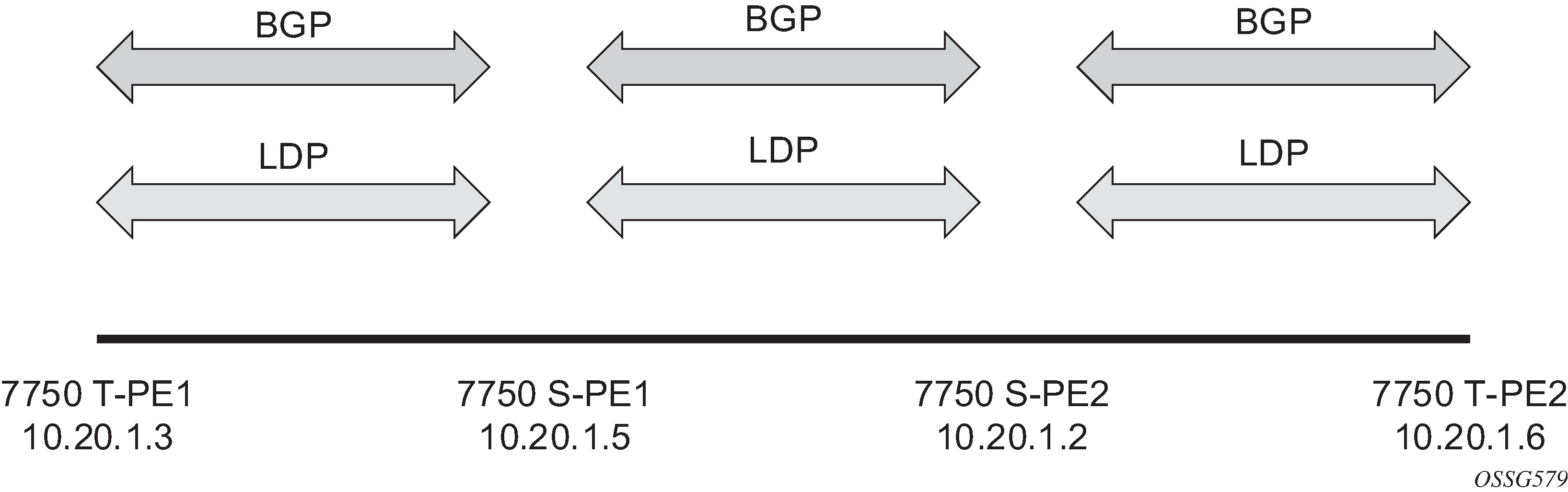
The example uses BGP to route dynamic MS-PWs and T-LDP to signal them. Therefore, each node must be configured to support the MS-PW address family under BGP, and BGP and LDP peerings must be established between the T-PEs/S-PEs. The appropriate BGP export policies must also be configured.
Next, pseudowire routing must be configured on each node. This includes an S-PE address for every participating node, and one or more local prefixes on the T-PEs. MS-PW paths and static routes may also be configured.
When this routing and signaling infrastructure is established, spoke-sdp-fecs can be configured on each of the T-PEs, as follows:
config
   router
      ldp
         targeted-session
            peer 10.20.1.5
            exit
         exit
      policy-options
         begin
         policy-statement "exportMsPw"
            entry 10
               from
                  family ms-pw
               exit
               action accept
               exit
            exit
         exit
         commit
      exit
      bgp
         family ms-pw
         connect-retry 1
         min-route-advertisement 1
         export "exportMsPw"
         rapid-withdrawal
         group "ebgp"
            neighbor 10.20.1.5
               multihop 255
               peer-as 200
            exit
         exit
     exit
config
   service
      pw-routing
         spe-address 3:10.20.1.3
         local-prefix 3:10.20.1.3 create
         exit
         path "path1_to_F" create
            hop 1 10.20.1.5
            hop 2 10.20.1.2
            no shutdown
        exit
     exit
     epipe 1 name "XYZ Epipe 1" customer 1 create
        description "Default epipe
             description for service id 1"
        service-mtu 1400
        sap 2/1/1:1 create
        exit
        spoke-sdp-fec 1 fec 129 aii-type 2 create
           retry-timer 10
           retry-count 10
           saii-type2 3:10.20.1.3:1
           taii-type2 6:10.20.1.6:1
           no shutdown
        exit
        no shutdown
     exit
config
   router
      ldp
         targeted-session
            peer 10.20.1.2
            exit
         exit
         …
      policy-options
         begin
         policy-statement "exportMsPw"
            entry 10
               from
                  family ms-pw
               exit
               action accept
               exit
            exit
         exit
         commit
      exit

      bgp
         family ms-pw
         connect-retry 1
         min-route-advertisement 1
         export "exportMsPw"
         rapid-withdrawal
         group "ebgp"
            neighbor 10.20.1.2
               multihop 255
               peer-as 300
            exit
         exit
     exit
config
   service
      pw-routing
         spe-address 6:10.20.1.6
         local-prefix 6:10.20.1.6 create
         exit
         path "path1_to_F" create
            hop 1 10.20.1.2
            hop 2 10.20.1.5
            no shutdown
        exit
     exit
     epipe 1 name "XYZ Epipe 1" customer 1 create
        description "Default epipe
             description for service id 1"
service-mtu 1400
        sap 1/1/3:1 create
        exit
        spoke-sdp-fec 1 fec 129 aii-type 2 create
           retry-timer 10
           retry-count 10
           saii-type2 6:10.20.1.6:1
           taii-type2 3:10.20.1.3:1
           no shutdown
        exit
        no shutdown
     exit
config
   router
      ldp
         targeted-session
            peer 10.20.1.3
            exit
            peer 10.20.1.2
            exit
         exit
         …
      bgp
         family ms-pw
         connect-retry 1
         min-route-advertisement 1
         rapid-withdrawal
         group "ebgp"
            neighbor 10.20.1.2
               multihop 255
               peer-as 300
            exit
            neighbor 10.20.1.3
               multihop 255
               peer-as 100
            exit
         exit
     exit

   service
      pw-routing
         spe-address 5:10.20.1.5
      exit
config
   router
      ldp
         targeted-session
            peer 10.20.1.5
            exit
            peer 10.20.1.6
            exit
         exit
         …
      bgp
         family ms-pw
         connect-retry 1
         min-route-advertisement 1
         rapid-withdrawal
         group "ebgp"
            neighbor 10.20.1.5
               multihop 255
               peer-as 200
            exit
            neighbor 10.20.1.6
               multihop 255
               peer-as 400
            exit
         exit
     exit
service
      pw-routing
         spe-address 2:10.20.1.2
      exit
VLL resilience with two destination PE nodes
VLL resilience shows the application of pseudowire redundancy to provide Ethernet VLL service resilience for broadband service subscribers accessing the broadband service on the service provider BRAS.
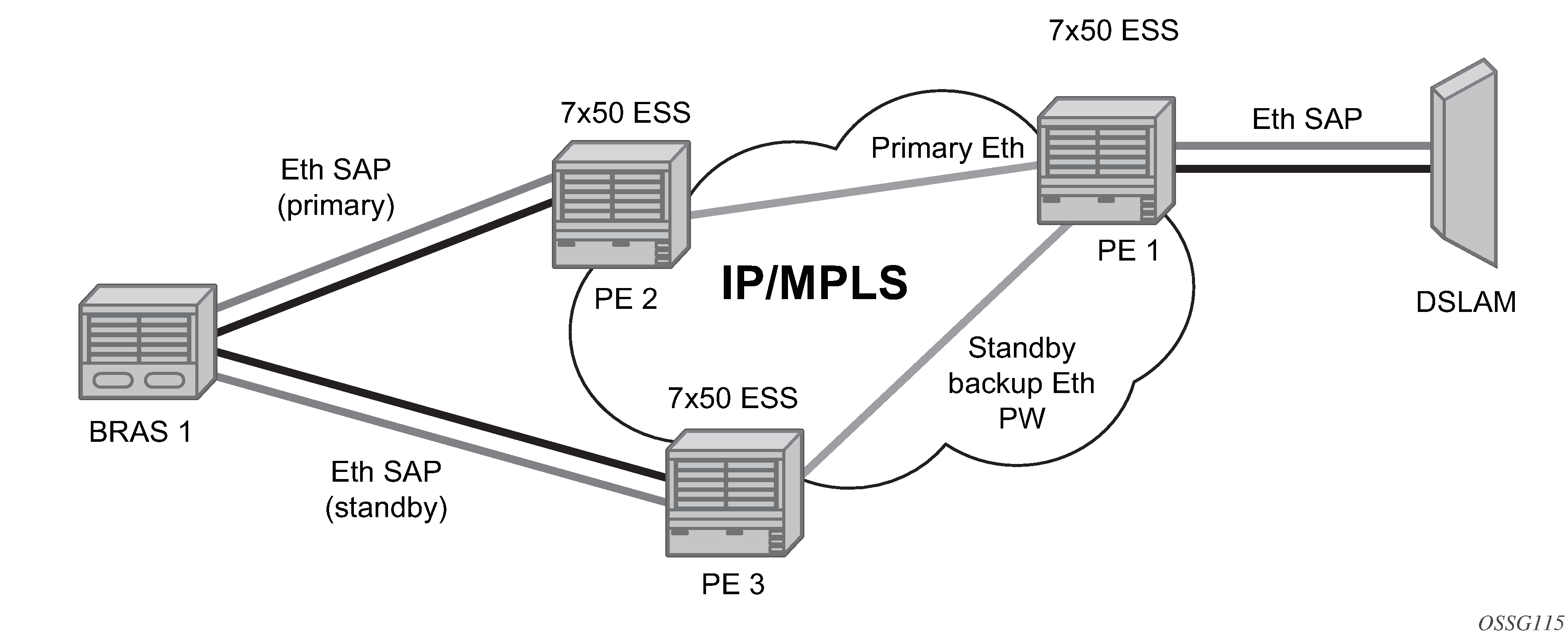
If the Ethernet SAP on PE2 fails, PE2 notifies PE1 of the failure by either withdrawing the primary pseudowire label it advertised or by sending a pseudowire status notification with the code set to indicate a SAP defect. PE1 receives it and immediately switches its local SAP to forward over the secondary standby spoke-SDP. To avoid black holing of packets during the switching of the path, PE1 accepts packets received from PE2 on the primary pseudowire while transmitting over the backup pseudowire. However, in other applications such as those described in Access node resilience using MC-LAG and pseudowire redundancy, it is important to minimize service outage to end users.
When the SAP at PE2 is restored, PE2 updates the new status of the SAP by sending a new label mapping message for the same pseudowire FEC or by sending pseudowire status notification message indicating that the SAP is back up. PE1 then starts a timer and reverts to the primary at the expiry of the timer. By default, the timer is set to 0, which means PE1 reverts immediately. A special value of the timer (infinity) means that PE1 should never revert to the primary pseudowire.
The behavior of the pseudowire redundancy feature is the same if PE1 detects or is notified of a network failure that brought the spoke-SDP status to operationally down. The following events cause PE1 to trigger a switchover to the secondary standby pseudowire.
-
The T-LDP peer (remote PE) node withdraws the pseudowire label.
-
The T-LDP peer signals a FEC status indicating a pseudowire failure or a remote SAP failure.
-
The T-LDP session to peer node times out.
-
The SDP binding or VLL service goes down as a result of a network failure condition, such as the SDP to the peer node going operationally down, or the SDP binding going operationally down because the VCCV BFD session is going down.
The SDP type for the primary and secondary pseudowires need not be the same. That is, the user can protect an RSVP-TE based spoke-SDP with an LDP or GRE based one. This provides the ability to route the path of the two pseudowires over different areas of the network. All VLL service types, for example, Epipe and Ipipe, are supported on the 7750 SR.
Nokia routers support the ability to configure multiple secondary standby pseudowire paths. For example, PE1 uses the value of the user-configurable precedence parameter associated with each spoke-SDP to select the next available pseudowire path after the failure of the current active pseudowire (whether it is the primary or one of the secondary pseudowires). The revertive operation always switches the path of the VLL back to the primary pseudowire though. There is no revertive operation between secondary paths, meaning that the path of the VLL is not switched back to a secondary pseudowire of higher precedence when the latter comes back up again.
Nokia routers support the ability for a user-initiated manual switchover of the VLL path to the primary or any of the secondary, be supported to divert user traffic in case of a planned outage such as in node upgrade procedures.
On the 7750 SR, this application can make use of all types of VLL supported on SR-series routers. However, if a SAP is configured on an MC-LAG instance, only the Epipe service type is allowed.
Master-slave operation
This section describes a mechanism in which one end on a pseudowire (the "master") dictates the active PW selection, which is followed by the other end of the PW (the "slave"). This mechanism and associated terminology is specified in RFC6870.
This section describes master-slave pseudowire redundancy. It adds the ability for the remote peer to react to the pseudowire standby status notification, even if only one spoke-SDP terminates on the VLL endpoint on the remote peer, by blocking the transmit (Tx) direction of a VLL spoke-SDP when the far-end PE signals standby. This solution enables the blocking of the Tx direction of a VLL spoke-SDP at both master and slave endpoints when standby is signaled by the master endpoint. This approach satisfies a majority of deployments where bidirectional blocking of the forwarding on a standby spoke-SDP is required.
Master-slave pseudowire redundancy shows the operation of master-slave pseudowire redundancy. In this scenario, an Epipe service is provided between CE1 and CE2. CE2 is dual-homed to PE2 and PE3; therefore, PE1 is dual-homed to PE2 and PE3 using Epipe spoke-SDPs. The objective of this feature is to ensure that only one pseudowire is used for forwarding in both directions by PE1, PE2, and PE3 in the absence of a native dual homing protocol between CE2 and PE2/PE3, such as MC-LAG. In normal operating conditions (the SAPs on PE2 and PE3 toward CE2 are both up and there are no defects on the ACs to CE2), PE2 and PE3 cannot choose which spoke-SDP to forward on, based on the status of the AC redundancy protocol.
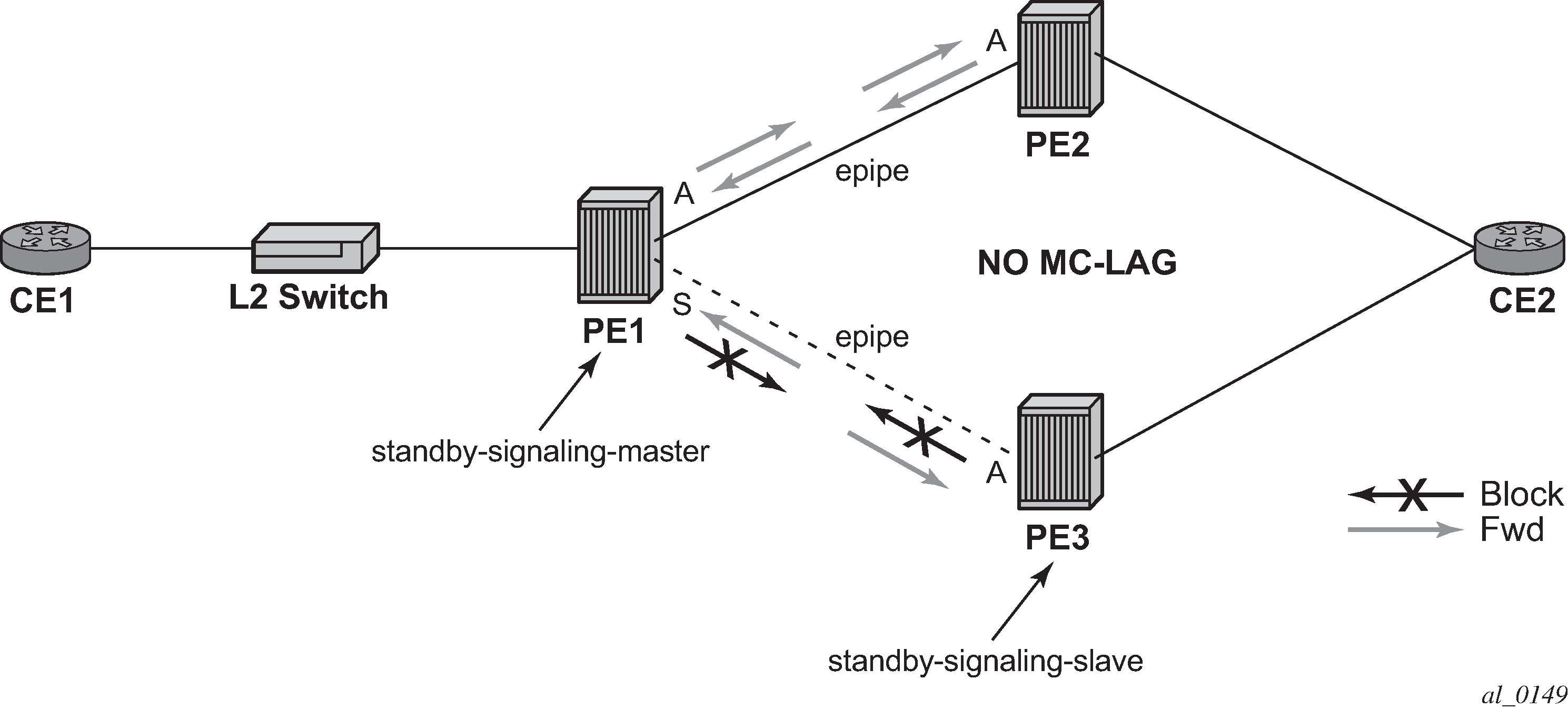
Master-slave pseudowire redundancy adds the ability for the remote peer to react to the pseudowire standby status notification, even if only one spoke-SDP terminates on the VLL endpoint on the remote peer. When the CLI command standby-signaling-slave is enabled at the spoke-SDP or explicit endpoint level in PE2 and PE3, then any spoke-SDP for which the remote peer signals PW FWD Standby is blocked in the transmit direction.
This is achieved as follows. The standby-signaling-master state is activated on the VLL endpoint in PE1. In this case, a spoke-SDP is blocked in the transmit direction at this primary endpoint if it is either in operDown state, or it has lower precedence than the highest precedence spoke-SDP, or the specific peer PE signals one of the following pseudowire status bits:
Pseudowire not forwarding (0x01)
SAP (ingress) receive fault (0x02)
SAP (egress) transmit fault (0x04)
SDP binding (ingress) receive fault (0x08)
SDP binding (egress) transmit fault (0x10)
That the specified spoke-SDP has been blocked is signaled to the LDP peer through the pseudowire status bit (PW FWD Standby (0x20)). This prevents traffic being sent over this spoke-SDP by the remote peer, but only if that remote peer supports and reacts to pseudowire status notification. Previously, this applied only if the spoke-SDP terminates on an IES, VPRN, or VPLS. However, if standby-signaling-slave is enabled at the remote VLL endpoint, the Tx direction of the spoke-SDP is also blocked, according to the rules in Operation of master-slave pseudowire redundancy with existing scenarios.
Although master-slave operation provides bidirectional blocking of a standby spoke-SDP during steady-state conditions, it is possible that the Tx directions of more than one slave endpoint can be active for transient periods during a fail-over operation. This is because of the slave endpoints transitioning a spoke-SDP from standby to active receiving and, or processing a pseudowire preferential forwarding status message before those endpoints transitioning a spoke-SDP to standby. This transient condition is most likely when a forced switchover is performed, or the relative preferences of the spoke-SDPs are changed, or the active spoke-SDP is shutdown at the primary endpoint. During this period, loops of unknown traffic may be observed. Fail-overs because of common network faults that can occur during normal operation, or a failure of connectivity on the path of the spoke-SDP or the SAP, would not result in such loops in the data path.
Interaction with SAP-specific OAM
If all of the spoke-SDPs bound to a SAP at a slave PE are selected as standby, then this should be treated from a SAP OAM perspective in the same manner as a fault on the service: an SDP binding down or remote SAP down. That is, a fault should be indicated to the service manager. If SAP-specific OAM is enabled toward the CE, such as Ethernet Continuity Check Message (CCM), Ethernet Link Management Interface (E-LMI), or FR LMI, then this should result in the appropriate OAM message being sent on the SAP. This can enable the remote CE to avoid forwarding traffic toward a SAP that drops it.
Example of SAP OAM interaction with master-slave pseudowire redundancy shows an example for the case of Ethernet LMI.
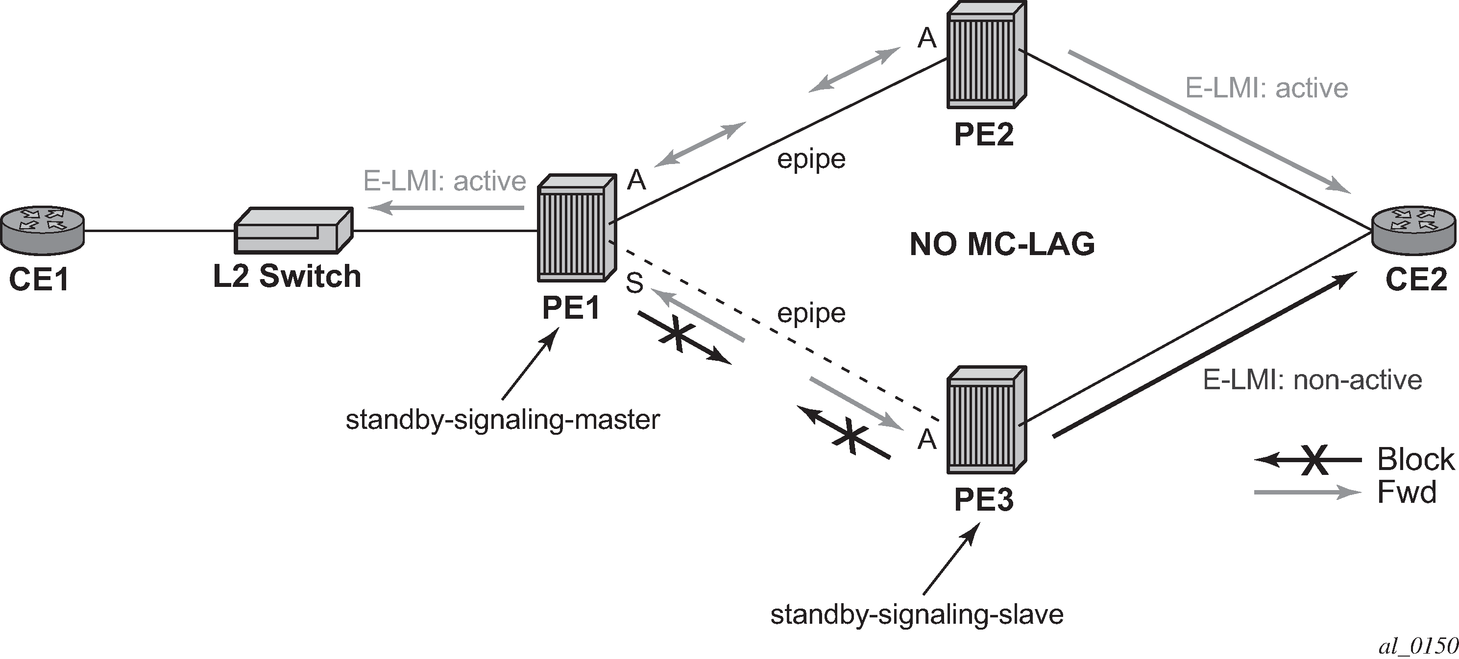
Local rules at slave VLL PE
It is not possible to configure standby-signaling-slave on endpoints or spoke-SDPs that are bound to an IES, VPRN, ICB, or MC-EP, or that are part of an MC-LAG or MC-APS.
If standby-signaling-slave is configured on a specific spoke-SDP or explicit endpoint, then the following rules apply. The rules describe the case of several spoke-SDPs in an explicit endpoint. The same rules apply to the case of a single spoke-SDP outside of an endpoint where no endpoint exists:
-
Rule for processing endpoint SAP active/standby status bits:
Because the SAP in endpoint X is never a part of an MC-LAG/MC-APS instance, a forwarding status of active is always advertised.
Rules for processing and merging local and received endpoint objects with an up or down operational status:
-
Endpoint X is operationally up if at least one of its objects is operationally up. It is Down if all of its objects are operationally down.
-
If all objects in endpoint X performed any or all of the following operations, the node must send status bits of SAP down over all Y endpoint spoke-SDPs:
-
transitioned locally to down state
-
received a SAP down notification via remote T-LDP or via SAP-specific OAM signal
-
received status bits of SDP-binding down
-
received states bits of PW not forwarding
-
-
Endpoint Y is operationally up if at least one of its objects is operationally up. It is down if all its objects are operationally down.
-
If a spoke-SDP in endpoint Y, including the ICB spoke-SDP, transitions locally to down state, the node must send T-LDP SDP-binding down status bits on this spoke-SDP.
-
If a spoke-SDP in endpoint Y received T-LDP SAP down status bits, and, or T-LDP SDP-binding down status bits, and, or status bits of PW not forwarding, the node saves this status and takes no further action. The saved status is used for selecting the active transmit endpoint object.
-
If all objects in endpoint Y, or a single spoke-SDP that exists outside of an endpoint (and no endpoint exists), the node must send a SAP down notification on the X endpoint SAP via the SAP-specific OAM signal, if applicable:
-
transitioned locally to down state
-
received status bits of T-LDP SAP down
-
received status bits of T-LDP SDP-binding down
-
received status bits of PW not forwarding
-
received status bits of PW FWD standby
-
-
If the peer PE for a specified object in endpoint Y signals PW FWD standby, the spoke-SDP must be blocked in the transmit direction and the spoke-SDP is not eligible for selection by the active transmit selection rules.
-
If the peer PE for a specified object in endpoint Y does not signal PW FWD standby, then spoke-SDP is eligible for selection.
Operation of master-slave pseudowire redundancy with existing scenarios
This section discusses how master-slave pseudowire redundancy could operate.
VLL resilience path example
VLL resilience shows a VLL resilience path example. An example configuration follows.

A revert-time value of zero (default) means that the VLL path is switched back to the primary immediately after it comes back up.
PE-1
configure service epipe 1
endpoint X
exit
endpoint Y
   revert-time 0
   standby-signaling-master
   exit
   sap 1/1/1:100 endpoint X
   spoke-sdp 1:100 endpoint Y
precedence primary
   spoke-sdp 2:200 endpoint Y
precedence 1

PE-2
configure service epipe 1
   endpoint X
   exit
   sap 2/2/2:200 endpoint X
   spoke-sdp 1:100
      standby-signaling-slave

PE-3
configure service epipe 1
   endpoint X
   exit
   sap 3/3/3:300 endpoint X
   spoke-sdp 2:200
      standby-signaling-slave
VLL resilience for a switched pseudowire path
VLL resilience with pseudowire switching displays VLL resilience for a switched pseudowire path example. An example configuration follows.
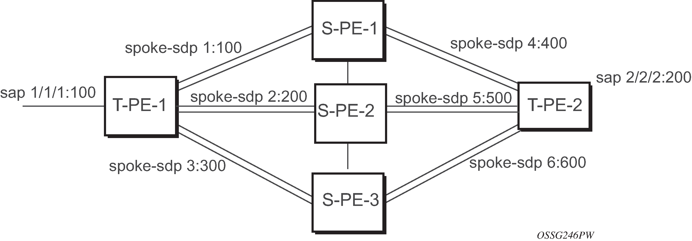
T-PE-1
configure service epipe 1
   endpoint X
   exit
   endpoint Y
   revert-time 100
   standby-signaling-master
   exit
   sap 1/1/1:100 endpoint X
   spoke-sdp 1:100 endpoint Y
      precedence primary
   spoke-sdp 2:200 endpoint Y
      precedence 1
   spoke-sdp 3:300 endpoint Y
      precedence 1

T-PE-2
configure service epipe 1
   endpoint X
   exit
   endpoint Y
   revert-time 100
   standby-signaling-slave
   exit
   sap 2/2/2:200 endpoint X
   spoke-sdp 4:400 endpoint Y
      precedence primary
   spoke-sdp 5:500 endpoint Y
      precedence 1
   spoke-sdp 6:600 endpoint Y
      precedence 1
VC switching indicates a VC cross-connect so that the service manager does not signal the VC label mapping immediately but puts S-PE-1 into passive mode, as follows:
configure service epipe 1 vc-switching
   spoke-sdp 1:100
   spoke-sdp 4:400
Pseudowire SAPs
For information about how to use pseudowire SAPs with Layer 2 services, see the 7450 ESS, 7750 SR, 7950 XRS, and VSR Layer 3 Services Guide: IES and VPRN.
Epipe using BGP-MH site support for Ethernet tunnels
Using Epipe in combination with G.8031 and BGP multihoming in the same manner as VPLS offers a multi-chassis resiliency option for Epipe services that is a non-learning and non-flooded service. MC-LAG (see Access node resilience using MC-LAG and pseudowire redundancy) offers access node redundancy with active/stand-by links while Ethernet tunnels offer per service redundancy with all active links and active or standby services. G.8031 offers an end-to-end service resiliency for Epipe and VPLS services. BGP-MH site support for Ethernet tunnels offers Ethernet edge resiliency for Epipe services that integrates with MPLS pseudowire redundancy.
BGP-MH site support for Ethernet tunnels shows the BGP-MH site support for Ethernet tunnels, where a G.8031 edge device (A) is configure with two provider edge switches (B and C). G.8031 is configured on the Access devices (A and F). An Epipe endpoint service is configured along with BGP Multihoming and Pseudowire Redundancy on the provider edge nodes (B/C and D/E). This configuration offers a fully redundant Epipe service.
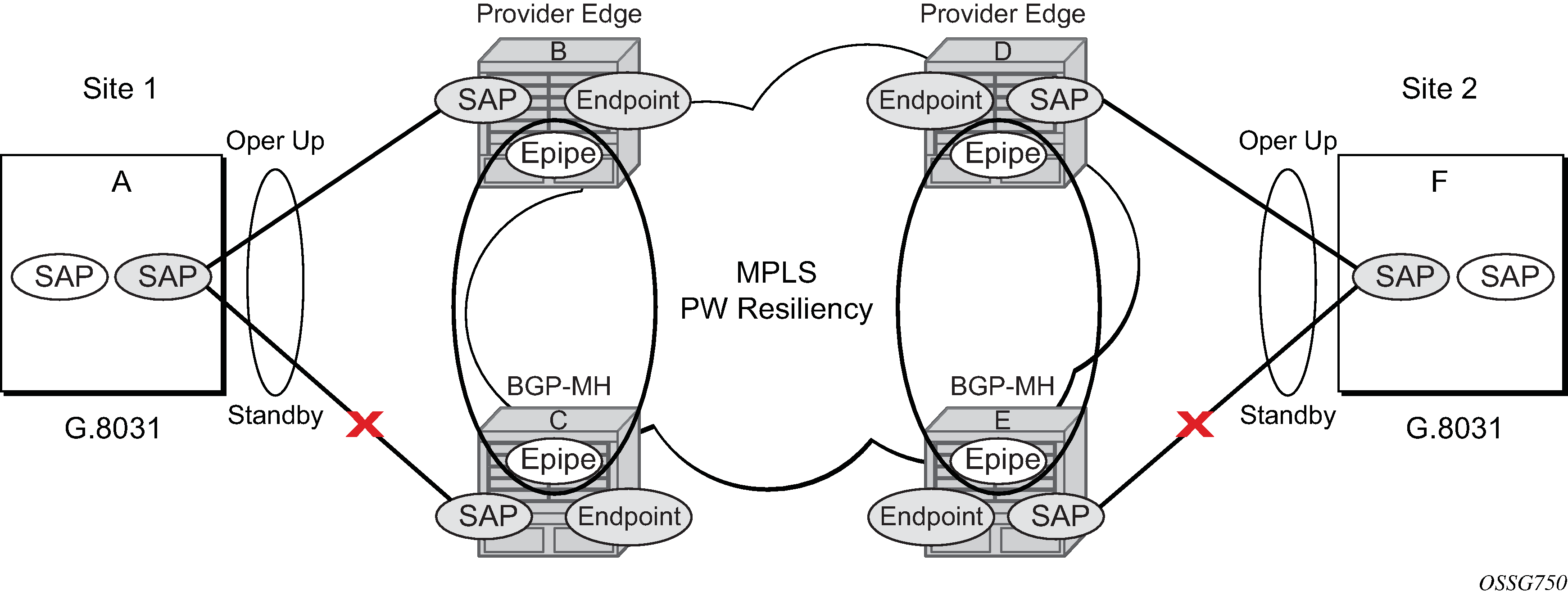
Operational overview
G.8031 offers a number of redundant configurations. Normally, it offers the ability to control two independent paths for 1:1 protection. In the BGP-MH site support for Ethernet tunnels case, BGP drives G.8031 as a slave service. In this case, the provider edge operates using only standard 802.1ag MEPs with CCM to monitor the paths. G.8031 for slave operation shows an Epipe service on a Customer Edge (CE) device that uses G.8031 with two paths and two MEPs. The paths can use a single VLAN of dot1q or QinQ encapsulation.
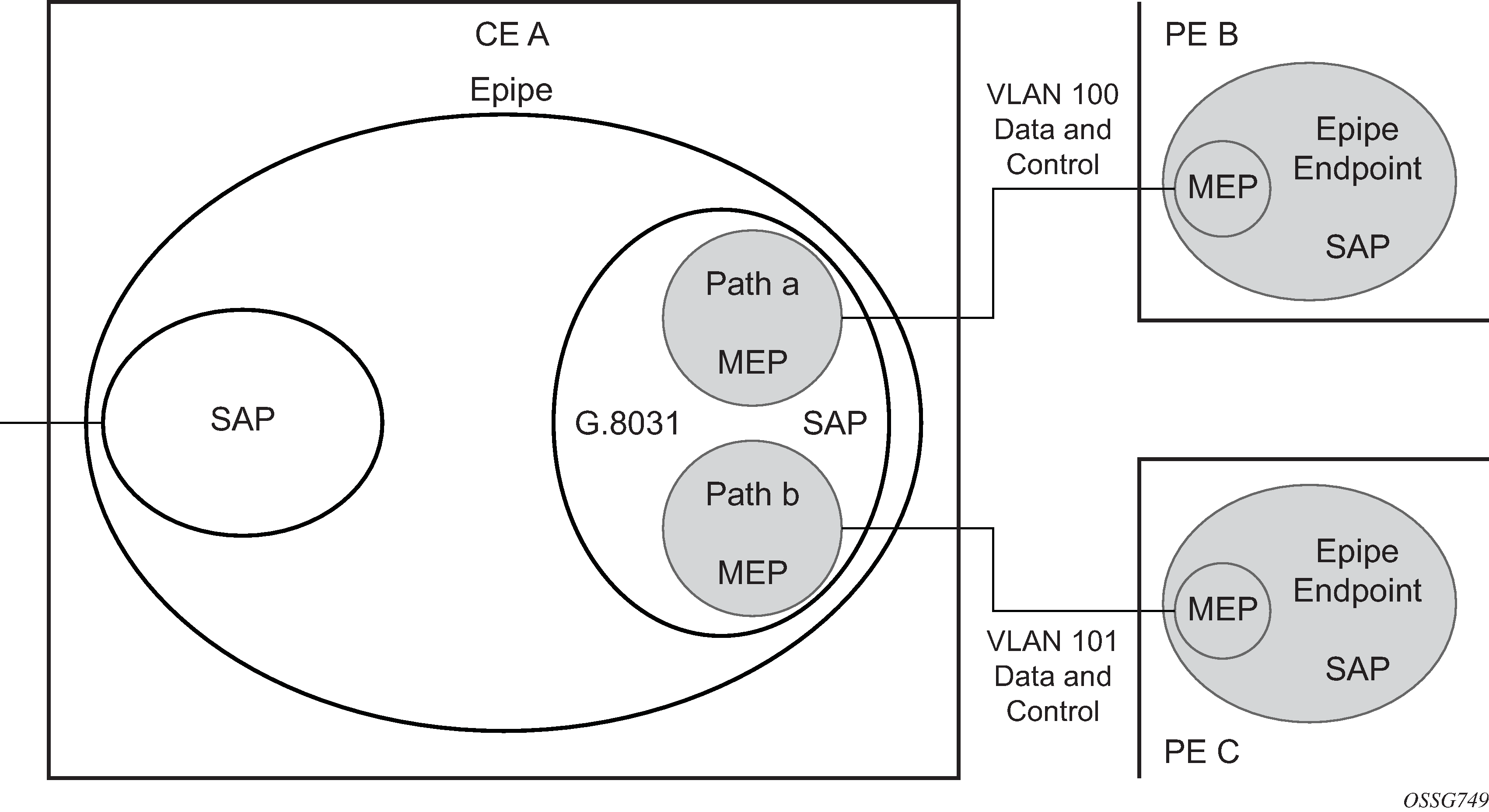
In a single-service deployment, the control (CFM) and data share the same port and VID. For multiple services for scaling, fate sharing is allowed between multiple SAPs, but all SAPs within a group must be on the same physical port.
To get fate sharing for multiple services with this feature, a dedicated G.8031 CE-based service (one VLAN) is connected to a Epipe SAP on a PE, which uses BGP-MH and operational groups to control other G.8031 tunnels. This dedicated G.8031 service still has data control capabilities, but the data Epipe service is not bearing user data packets. On the CE, this G.8031 is only used for group control. Making this a dedicated control (CFM) for a set of G.8031 tunnels is to simplify operation and allow individual disabling of services. Using a dedicated G.8031 service to both control and to carry data traffic is allowed.
Fate sharing from the PE side is achieved using BGP and operational groups. G.8031 Epipe services can be configured on the CE as regular non-fate shared G.8031 services, but because of the configuration on the PE side, these Ethernet tunnels are treated as a group following the one designated control service. The G.8031 control logic on the CE is a slave to the BGP-MH control.
On the CE, G.8031 allows independent configuration of VIDs on each path. On the PE, the Epipe or endpoint that connects to the G.8031 service must have a SAP with the corresponding VID. If the G.8031 service has a Maintenance End Point (MEP) for that VID, the SAP should be configured with a MEP. The MEPs on the paths on the CE signal standard interface status TLV (ifStatusTLV), No Fault (Up), and Fault (Down). The MEPs on the PE (Epipe or endpoint) also use signaling of ifStatusTLV No Fault (Up), and Fault (Down) to control the G.8031 SAP. However, in the 7750 SR, 7450 ESS, and 7950 XRS model, fate shared Ethernet tunnels with no MEP are allowed. In this case, it is up to the CE to manage these CE-based fate shared tunnels.
Interface status signaling (ifStatusTLV) is used to control the G.8031 tunnel from the PE side. Normally the CE signals No Fault (Up) in the path SAP MEP ifStatusTLV before the BGP-MH causes the SAP MEP to become active by signaling No Fault (Up).
Detailed operation
For this feature, BGP-MH is used as the master control and the Ethernet tunnel is a slave. The G.8031 on the CE is unaware that it is being controlled. While a single Epipe service is configured and serves as the control for the CE connection, allowing fate sharing, all signaling to the CE is based on the ifStatusTLV per G.8031 tunnel. By controlling G.8031 with BGP-MH, the G.8031 CE is forced to be a slave to the PE BGP-MH election. BGP-MH election is controlled by the received VPLS preference or BGP local-preference, or the PE ID (IP address of provider edge) if local-preference is equal to VPLS preference. There may be traps generated on the CE side for some G.8031 implementations, but these can be suppressed or filtered to allow this feature to operate.
There are two configuration options:
Every G.8031 service SAP terminates on a single Epipe that has BGP-MH. These Epipes may use endpoints with or without ICBs.
A control Epipe service monitors a single SAP that is used for group control of fate shared CE services. In this case, the Epipe service has an SAP that serves as the control termination for one Ethernet tunnel connection. The group fate sharing SAPs may or may not have MEPs if they use shared fate. In this case, the Epipe may have endpoints but does not support ICBs.
The MEP ifStatusTlv and CCM are used for monitoring the PE to CE SAP. MEP ifStatusTlv is used to signal that the Ethernet tunnel inactive and CCM is used as an aliveness mechanism. There is no G.8031 logic on the PE; the SAP is controlling the corresponding CE SAP.
Example operation of G.8031 BGP-MH
Any Ethernet tunnel actions (force, lock) on the CE (single site) do not control the action to switch paths directly, but they may influence the outcome of BGP-MH if they are on a control tunnel. If a path is disabled on the CE, the result may force the SAP with an MEP on the PE to eventually take the SAP down; Nokia recommends running commands from the BGP-MH side to control these connections.

SAP MEP signaling lists the SAP MEP signaling shown in Full redundancy G.8031 Epipe and BGP-MH. For a description of the events shown in this example operation, see Events in example operation.
| G.8031 ET on CE | Path A MEP facing node B local ifStatus | Path B MEP facing node C local ifStatus | Path B PE MEP ifStatus | Path B PE MEP ifStatus | |
|---|---|---|---|---|---|
1 |
Down (inactive) |
No Fault1 | No Fault |
Fault |
Fault |
2 |
Up use Path A |
No Fault |
No Fault |
No Fault |
Fault |
3 |
Up use Path B |
No Fault |
No Fault |
Fault |
No Fault |
4 |
Down Path A fault |
Fault2 | No Fault |
Fault |
Fault |
5 |
Down Path A and B fault at A |
Fault |
No Fault |
Fault |
Fault |
6 |
Partitioned Network Use Path Precedence Up use Path A |
No Fault |
No Fault |
No Fault |
No Fault |
Events in example operation
The following describes the events for switchover in Full redundancy G.8031 Epipe and BGP-MH. This configuration uses operational groups. The nodes of interest are A, B, and C listed in SAP MEP signaling.
-
A single G.8031 SAP that represents the control for a group of G.8031 SAPs is configured on the CE.
-
The Control SAP does not normally carry any data; however, it can if needed.
-
An Epipe service is provisioned on each PE node (B/C), only for control (no customer traffic flows over this service).
-
On CE A, there is an Epipe Ethernet tunnel (G.8031) control SAP.
-
The Ethernet tunnel has two paths:
-
one facing B
-
one facing C
-
-
PE B has an Epipe control SAP that is controlled by the BGP-MH site and PE C also has the corresponding SAP that is controlled by the same BGP-MH site.
-
-
At node A, there are MEPs configured under each path that check connectivity on the A-B and A-C links. At nodes B and C, there is a MEP configured under their respective SAPs with fault propagation enabled with the use of ifStatusTlv.
-
Initially, assume there is no link failure:
-
SAPs on node A have ifStatusTLV No Fault to B and C (no MEP fault detected at A); see SAP MEP signaling row 1 (Fault is signaled in the other direction PE to CE).
-
BGP-MH determines which is the master or Designated Forwarder (DF).
-
Assume SAP on node B is picked as the DF.
-
The MEP at Path A-B signals ifStatusTlv No Fault. Because of this signal, the MEP under the node A path facing node B detects the path to node B is usable by the path manager on A.
-
-
At the CE node A, Path A-C becomes standby and is brought down; see SAP MEP signaling row 2.
-
Because fault propagation is enabled under the SAP node C MEP, and ifStatusTLV is operationally Down, the Path remains in the present state.
-
Under these conditions, the MEP under the node A path facing node C detects the fault and informs Ethernet manager on node A.
-
Node A then considers bringing path A-C down.
-
ET port remains up ecause the path A-B is operationally up. This is a stable state.
-
-
On nodes B and C, each Epipe-controlled SAP is the sole (controlling) member of an operational group.
-
Other data SAPs may be configured for fate shared VLANs (Ethernet tunnels) and to monitor the control SAP.
-
The SAPs facing the CE node A share the fate of the control SAP and follow the operation.
-
If there is a break in path A-B connectivity (CCM timeout or LOS on the port for link A-B), the following actions take place:
-
On node A, the path MEP detects connectivity failure and informs Ethernet tunnel manager; see SAP MEP signaling row 4.
-
At this point, the Ethernet tunnel is down because both path A-B and path A-C are down.
-
The CE node A Ethernet tunnel goes down.
-
At node B on the PE, the SAP also detects the failure and the propagation of fault status goes to BGP-MH; see SAP MEP signaling row 4.
-
This in turn feeds into BGP-MH, which deems the site non-DF and makes the site standby.
-
Because the SAP at node B is standby, the service manager feeds this to CFM, which then propagates a Fault toward node A. This is a cyclic fault propagation. However, because path A-B is broken, the situation is stable; see SAP MEP signaling row 5.
-
There is traffic loss during the BGP-MH convergence.
-
Load sharing mode is recommended when using a 7450 as a CE node A device.
-
BGP-MH signals that node C is now the DF; see SAP MEP signaling row 3.
-
-
BGP-MH on node C elects a SAP and brings it up.
-
ET port transitions to port A-C, and is operationally up. This is a stable state. The A-C SAPs monitoring the operational group on C transitions to operationally up.
Unidirectional failures: at point 6 the failure was detected at both ends. In the case of a unidirectional failure, CCM times out on one side.
-
In the case where the PE detects the failure, it propagates the failure to BGP-MH and the BGP-MH takes the site down causing the SAPs on the PE to signal a Fault to the CE.
-
In the case where G.8031 on the CE detects the failure, it takes the tunnel down and signals a fault to the PE, and then the SAP propagates that to BGP-MH.
BGP-MH site support for Ethernet tunnels operational group model
For operational groups, one or more services follow the controlling service. On node A, there is an ET SAP facing nodes B/C, and on nodes B/C there are SAPs of the Epipe on physical ports facing node A. Each of the PE data SAPs monitor their respective operational groups, meaning they are operationally up or down based on the operational status of the control SAPs. On node A, because the data SAP is on the ET logical port, it goes operationally down whenever the ET port goes down and similarly for going operationally up.
Alternatively, an Epipe service may be provisioned on each node for each G.8031 data SAP (one-for-one service with no fate sharing). On CE node A, there is a G.8031 Ethernet tunnel. The Ethernet tunnel has two paths: one facing node B and one facing node C. This option is the same as the control SAP, but there are no operational groups. However, now there is a BGP-MH site per service. For large sites, operational groups are more efficient.
BGP-MH specifics for MH site support for Ethernet tunnels
BGP multihoming for VPLS describes the procedures for using BGP to control resiliency for VPLS. These procedures are the same except that an Epipe service can be configured for BGP-MH.
PW redundancy for BGP-MH site support for Ethernet tunnels
Pseudowire redundancy service models and VLL resilience with pseudowire redundancy and switching are used for the MPLS network resiliency. BGP MH site support for Ethernet tunnels reuses this model.
T-LDP status notification handling rules of BGP-MH Epipes
Using VLL resilience with pseudowire redundancy and switching as a reference, the following are the rules for generating, processing, and merging T-LDP status notifications in VLL service with endpoints.
Rules for processing endpoint SAP active/standby status bits
The advertised admin forwarding status of active/standby reflects the status of the local Epipe SAP in BGP-MH instance. If the SAP is not part of an MC-LAG instance or a BGP-MH instance, the forwarding status of Active is always advertised.
-
When the SAP in endpoint X is part of a BGP-MH instance, a node must send T-LDP forwarding status bit of SAP active/standby over all Y endpoint spoke-SDPs, except the ICB spoke-SDP, whenever this (BGP-MH designated forwarder) status changes. The status bit sent over the ICB is always zero (Active by default).
-
When the SAP in endpoint X is not part of an MC-LAG instance or BGP-MH instance, then the forwarding status sent over all Y endpoint spoke-SDPs should always be set to zero (Active by default).
-
The received SAP active/standby status is saved and used for selecting the active transmit endpoint object Pseudowire Redundancy procedures.
Rules for processing, merging local, and received endpoint operational status
-
Endpoint X is operationally up if at least one of its objects is operationally Up. It is Down if all its objects are operationally down.
-
If the SAP in endpoint X transitions locally to the down state, or received a SAP Down notification via SAP-specific OAM signal (SAP MEP), the node must send T-LDP SAP down status bits on the Y endpoint ICB spoke-SDP only. BGP-MH SAPs support MEPs for ifStatusTLV signaling. All other SAP types cannot exist on the same endpoint as an ICB spoke-SDP because non Ethernet SAP cannot be part of an MC-LAG instance or a BGP-MH Instance.
-
If the ICB spoke-SDP in endpoint X transitions locally to Down state, the node must send T-LDP SDP-binding down status bits on this spoke-SDP.
-
If the ICB spoke-SDP in endpoint X received T-LDP SDP-binding down status bits or PW not forwarding status bits, the node saves this status and takes no further action. The saved status is used for selecting the active transmit endpoint object as per Pseudowire Redundancy procedures.
-
If all objects in endpoint X performed any or all of the following operations, the node must send status bits of SAP Down over all Y endpoint spoke-SDPs, including the ICB:
-
transitioned locally to the down state because of the operator or BGP-MH DF election
-
received a SAP down notification via remote T-LDP status bits or via SAP-specific OAM signal (SAP MEP)
-
received status bits of SDP-binding down
-
received status bits of PW not forwarding
-
-
Endpoint Y is operationally up if at least one of its objects is operationally Up. It is Down if all its objects are operationally down.
-
If a spoke-SDP in endpoint Y, including the ICB spoke-SDP, transitions locally to down state, the node must send T-LDP SDP-binding down status bits on this spoke-SDP.
-
If a spoke-SDP in endpoint Y, including the ICB spoke-SDP, performed any or all of the following operations, the node saves this status and takes no further action:
-
received T-LDP SAP down status bits
-
received T-LDP SDP-binding down status bits
-
received PW not forwarding status bits
The saved status is used for selecting the active transmit endpoint object as per Pseudowire Redundancy procedures.
-
-
If all objects in endpoint Y, except the ICB spoke-SDP, performed any or all of the following operations, the node must send status bits of SDP-binding down over the X endpoint ICB spoke-SDP only:
-
transitioned locally to the down state
-
received T-LDP SAP down status bits
-
received T-LDP SDP-binding down status bits
-
received PW not forwarding status bits
-
-
If all objects in endpoint Y performed any or all of the following operations, the node must send status bits of SDP-binding down over the X endpoint ICB spoke-SDP only, and must send a SAP down notification on the X endpoint SAP via the SAP-specific OAM signal:
-
transitioned locally to down state
-
received T- LDP SAP down status bits
-
received T-LDP SDP-binding down status bits
-
received PW not forwarding status bits
In this case the SAP MEP ifStatusTLV is operationally down and also signals the BGP-MH site, if this SAP is part of a BGP Site.
-
Operation for BGP-MH site support for Ethernet tunnels
A multihomed site can be configured on up to four PEs although two PEs are enough for most applications, with each PE having a single object SAP connecting to the multihomed site. SR OS G.8031 implementation with load sharing allows multiple PEs as well. The designated forwarder election chooses a single connection to be operationally up, with the other placed in standby. Only revertive behavior is supported.
Fate sharing (the status of one site can be inherited from another site) is achievable using monitor-groups.
The following are supported:
All Ethernet-tunnel G.8031 SAPs on CE:
7750 SR, 7450 ESS, or 7950 XRS G.8031 in load sharing mode (recommended)
7750 SR, 7450 ESS, or 7950 XRS G.8031 in non-load sharing mode
Epipe and endpoint with SAPs on PE devices.
Endpoints with PW.
Endpoints with active/standby PWs.
There are the following constraints with this feature:
Not supported with PBB Epipes.
Spoke SDP (pseudowire).
BGP signaling is not supported.
Cannot use BGP MH for auto-discovered pseudowire. This is achieved in a VPLS service using SHGs, which are not available in Epipes.
Other multi-chassis redundancy features are not supported on the multihomed site object, as follows:
MC-LAG
MC-EP
MC-Ring
MC-APS
Master and slave pseudowire is not supported.
Figure 32. Example topology full redundancy 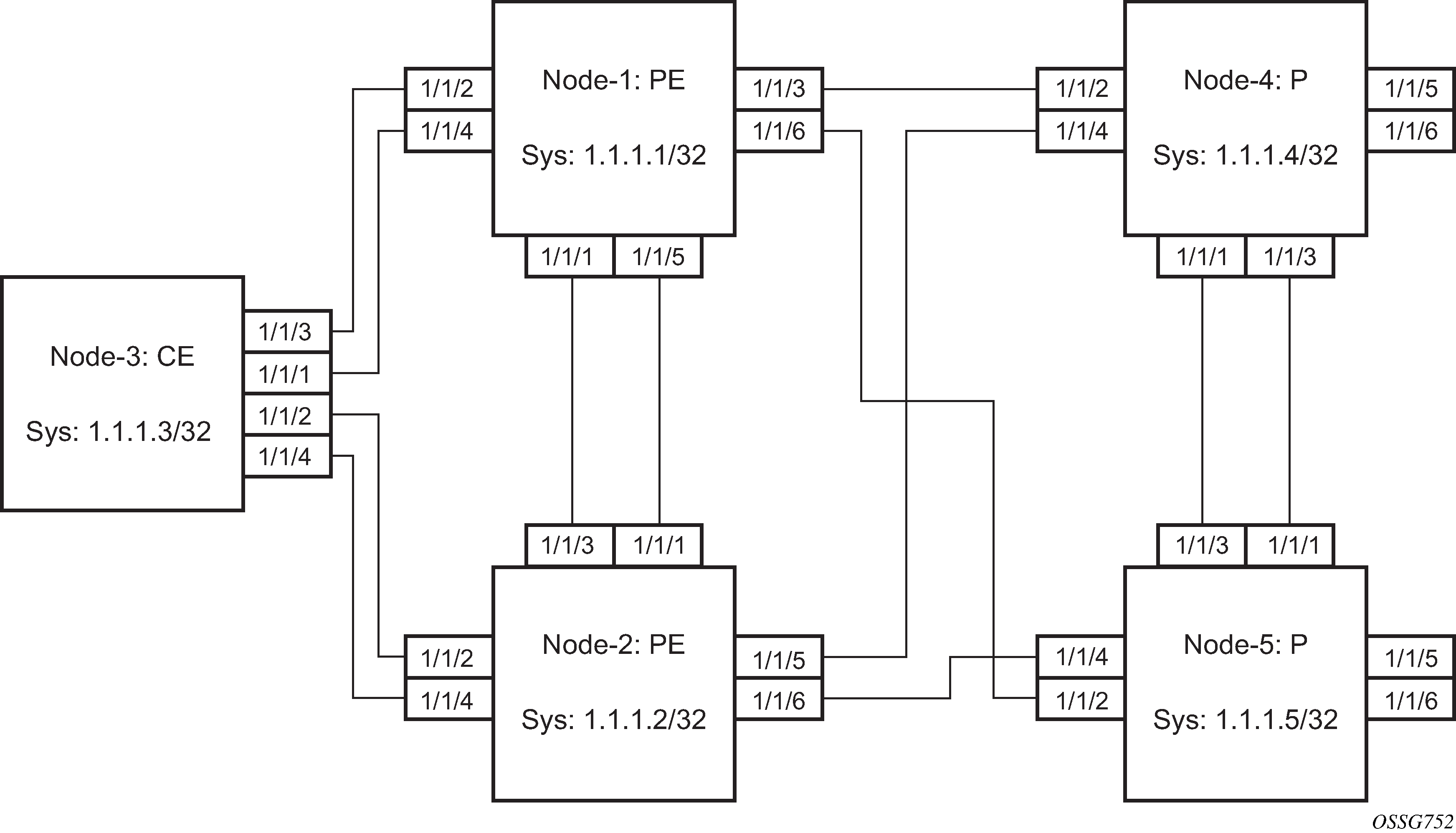
See the following Configuration examples for configuration examples derived from Example topology full redundancy.
Configuration examples
Node-1: Using operational groups and Ethernet CFM per SAP
#--------------------------------------------------
echo "Eth-CFM Configuration"
#--------------------------------------------------
    eth-cfm
        domain 100 format none level 3
            association 2 format icc-based name "node-3-site-1-0"
                bridge-identifier 1
                exit
                remote-mepid 310
            exit
            association 2 format icc-based name "node-3-site-1-1"
                bridge-identifier 100
                exit
                remote-mepid 311
            exit
        exit
    exit

#--------------------------------------------------
echo "Service Configuration"
#--------------------------------------------------
    service
        customer 1 create
            description "Default customer"
        exit
        sdp 2 mpls create
            far-end 10.1.1.4
            lsp "to-node-4-lsp-1"
            keep-alive
                shutdown
            exit
            no shutdown
        exit
        sdp 3 mpls create  //  Etcetera

        pw-template 1 create
            vc-type vlan
        exit
        oper-group "og-name-et" create
        exit
        oper-group "og-name-et100" create
        exit
        epipe 1 customer 1 create
            service-mtu 500
            bgp
                route-distinguisher 65000:1
                route-target export target:65000:1 import target:65000:1
            exit
            site "site-1" create
                site-id 1
                sap 1/1/2:1.1
                boot-timer 100
                site-activation-timer 2
                no shutdown
            exit
            endpoint "x" create
            exit
            endpoint "y" create
            exit
            sap 1/1/2:1.1 endpoint "x" create
                eth-cfm
                    mep 130 domain 100 association 2 direction down
                        fault-propagation-enable use-if-tlv
                        ccm-enable
                        no shutdown
                    exit
                exit
                oper-group "og-name-et"
            exit
            spoke-sdp 2:1 endpoint "y" create
                precedence primary
                no shutdown
            exit
            spoke-sdp 3:1 endpoint "y" create
                precedence 2
                no shutdown
            exit
            no shutdown
        exit
        epipe 100 customer 1 create
            description "Epipe 100 in separate opergroup"
            service-mtu 500
            bgp
                route-distinguisher 65000:2
                route-target export target:65000:2 import target:65000:2
            exit
            site "site-name-et100" create
                site-id 1101
                sap 1/1/4:1.100
                boot-timer 100
                site-activation-timer 2
                no shutdown
            exit

            endpoint "x" create
            exit
            endpoint "y" create
            exit
            sap 1/1/4:1.100 endpoint "x" create
                    eth-cfm
                    mep 131 domain 1 association 2 direction down
                        fault-propagation-enable use-if-tlv
                        ccm-enable
                        no shutdown
                    exit
                exit
                oper-group "og-name-et100"

            exit
            spoke-sdp 2:2 vc-type vlan endpoint "y" create
                precedence 1
                no shutdown
            exit
            spoke-sdp 3:2 vc-type vlan endpoint "y" create
                precedence 2
                no shutdown
            exit
            no shutdown
        exit

    exit
#--------------------------------------------------
echo "BGP Configuration"
#--------------------------------------------------
        bgp
            rapid-withdrawal
            rapid-update l2-vpn
            group "internal"
                type internal
                neighbor 10.1.1.2
                    family l2-vpn
                exit
            exit
        exit
    exit
Node-3: Using operational groups and Ethernet CFM per SAP
#--------------------------------------------------
echo "Eth-CFM Configuration"
#--------------------------------------------------
    eth-cfm
        domain 100 format none level 3
            association 2 format icc-based name "node-3-site-1-0"
                bridge-identifier 1
                exit
                ccm-interval 1
                remote-mepid 130
            exit
            association 2 format icc-based name "node-3-site-1-1"
                bridge-identifier 100
                exit
                ccm-interval 1
                remote-mepid 131
            association 3 format icc-based name "node-3-site-2-0"
                bridge-identifier 1
                exit
                ccm-interval 1
                remote-mepid 120
            exit
            association 3 format icc-based name "node-3-site-2-1"
                bridge-identifier 100
                exit
                ccm-interval 1
                remote-mepid 121
            exit
        exit
    exit

#--------------------------------------------------
echo "Service Configuration"
#--------------------------------------------------

  eth-tunnel 1
        description "Eth Tunnel loadsharing mode QinQ example"
        protection-type loadsharing
        ethernet
            encap-type qinq
        exit
        path 1
            member 1/1/3
            control-tag 1.1
            eth-cfm
                mep 310 domain 100 association 2
                    ccm-enable
                    control-mep
                    no shutdown
                exit
            exit
            no shutdown
        exit
        path 2
            member 1/1/4
            control-tag 1.2
            eth-cfm
                mep 320 domain 100 association 3
                    ccm-enablepath
                    control-mep
                    no shutdown
                exit
            exit
            no shutdown
        exit
        no shutdown
    exit
#--------------------------------------------------
echo "Ethernet Tunnel Configuration"
#--------------------------------------------------
    eth-tunnel 2
        description "Eth Tunnel QinQ"
        revert-time 10
        path 1
            precedence primary
            member 1/1/1
            control-tag 1.100
            eth-cfm
                mep 311 domain 100 association 2
                    ccm-enable
                    control-mep
                    no shutdown
                exit
            exit
            no shutdown
        exit
        path 2
            member 1/1/2
            control-tag 1.100
            eth-cfm
                mep 321 domain 100 association 3
                    ccm-enable
                    control-mep
                    no shutdown
                exit
            exit
            no shutdown
        exit
        no shutdown
    exit
#--------------------------------------------------
echo "Service Configuration"
#--------------------------------------------------
    service
        epipe 1 customer 1 create
            sap 2/1/2:1.1 create
            exit
            sap eth-tunnel-1 create
            exit
            no shutdown
        exit
        epipe 100 customer 1 create
            service-mtu 500
            sap 2/1/10:1.100 create
            exit
            sap eth-tunnel-2 create
            exit
            no shutdown
        exit
Configuration with fate sharing on node-3
In this example, the SAPs monitoring the operational groups do not need CFM if the corresponding SAP on the CE side is using fate sharing.
Node-1:
#--------------------------------------------------
echo "Service Configuration"  Oper-groups
#--------------------------------------------------
    service
        customer 1 create
            description "Default customer"
        exit
        sdp 2 mpls create
          ...

        exit
        pw-template 1 create
            vc-type vlan
        exit
        oper-group "og-name-et" create
        exit
        epipe 1 customer 1 create
            service-mtu 500
            bgp
                route-distinguisher 65000:1
                route-target export target:65000:1 import target:65000:1
            exit
            site "site-1" create
                site-id 1
                sap 1/1/2:1.1
                boot-timer 100
                site-activation-timer 2
                no shutdown
            exit
            endpoint "x" create
            exit
            endpoint "y" create
            exit
            sap 1/1/2:1.1 endpoint "x" create
                eth-cfm
                    mep 130 domain 100 association 1 direction down
                        fault-propagation-enable use-if-tlv
                        ccm-enable
                        no shutdown
                    exit
                exit
                oper-group "og-name-et"
            exit
            spoke-sdp 2:1 endpoint "y" create
                precedence primary
                no shutdown
            exit
            spoke-sdp 3:1 endpoint "y" create
                precedence 2
                no shutdown
            exit
            no shutdown
        exit
        epipe 2 customer 1 create
            description "Epipe 2 in opergroup with Epipe 1"
            service-mtu 500
            bgp
                route-distinguisher 65000:2
                route-target export target:65000:2 import target:65000:2
            exit
            endpoint "x" create
            exit
            endpoint "y" create
            exit
            sap 1/1/2:1.2 endpoint "x" create
                monitor-oper-group "og-name-et"
            exit
            spoke-sdp 2:2 vc-type vlan endpoint "y" create
                precedence 1
                no shutdown
            exit
            spoke-sdp 3:2 vc-type vlan endpoint "y" create
                precedence 2
                no shutdown
            exit
            no shutdown
        exit

    exit
Node-3:
#--------------------------------------------------
echo "Eth-CFM Configuration"
#--------------------------------------------------
    eth-cfm
        domain 100 format none level 3
            association 1 format icc-based name "node-3-site-1-0"
                bridge-identifier 1
                exit
                ccm-interval 1
                remote-mepid 130
            exit
            association 2 format icc-based name "node-3-site-2-0"
                bridge-identifier 2
                exit
                ccm-interval 1
                remote-mepid 120
            exit
        exit
    exit

#--------------------------------------------------
echo "Service Configuration"
#--------------------------------------------------

  eth-tunnel 2
        description "Eth Tunnel loadsharing mode QinQ example"
        protection-type loadsharing
        ethernet
            encap-type qinq
        exit
        path 1
            member 1/1/1
            control-tag 1.1
            eth-cfm
                mep 310 domain 100 association 1
                    ccm-enable
                    control-mep
                    no shutdown
                exit
            exit
            no shutdown
        exit
        path 2
            member 1/1/2
            control-tag 1.1
            eth-cfm
                mep 320 domain 100 association 2
                    ccm-enablepath
                    control-mep
                    no shutdown
                exit
            exit
            no shutdown
        exit
        no shutdown
    exit


#--------------------------------------------------
echo "Service Configuration"
#--------------------------------------------------
    service
        epipe 1 customer 1 create
            sap 1/10/1:1 create
            exit
            sap eth-tunnel-1 create
            exit
            no shutdown
        exit
#--------------------------------------------------
echo "Service Configuration for a shared fate Ethernet Tunnel"
#--------------------------------------------------
        epipe 2 customer 1 create
            sap 1/10/2:3 create
            exit
            sap eth-tunnel-1:2 create
                eth-tunnel
                    path 1 tag 1.2
                    path 2 tag 1.2
                exit
            exit
            no shutdown
        exit
Access node resilience using MC-LAG and pseudowire redundancy
Access node resilience shows the use of both Multi-Chassis Link Aggregation (MC-LAG) in the access network and pseudowire redundancy in the core network to provide a resilient end-to-end VLL service to the customers.
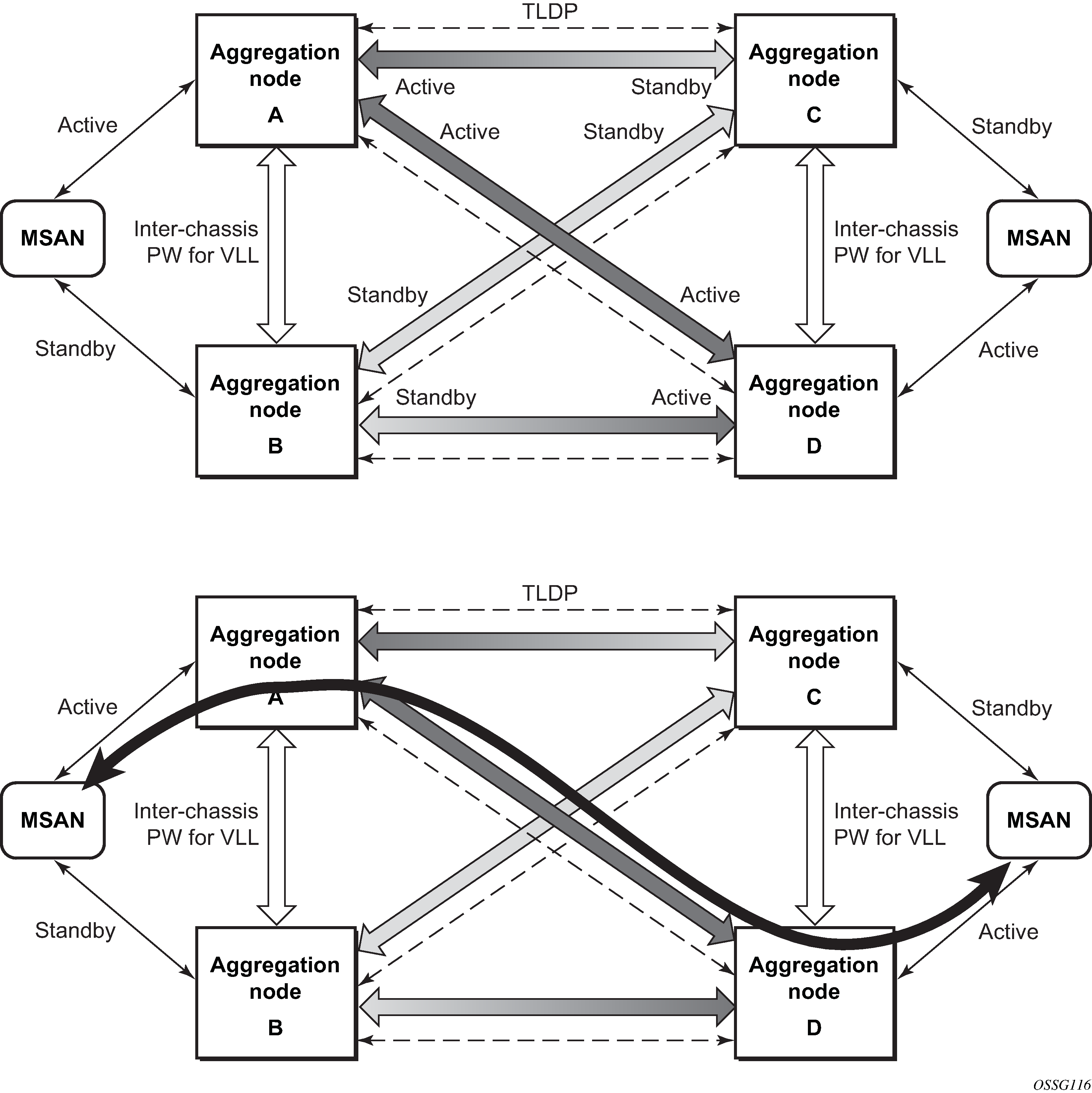
In this application, a new pseudowire status bit of active or standby indicates the status of the SAP in the MC-LAG instance in the SR-series aggregation node. All spoke-SDPs are of secondary type and there is no use of a primary pseudowire type in this mode of operation. Node A is in the active state according to its local MC-LAG instance and therefore advertises active status notification messages to both its peer pseudowire nodes; for example, nodes C and D. Node D performs the same operation. Node B is in the standby state according to the status of the SAP in its local MC-LAG instance, so advertises standby status notification messages to both nodes C and D. Node C performs the same operation.
An SR-series node selects a pseudowire as the active path for forwarding packets when both the local pseudowire status and the received remote pseudowire status indicate active status. However, an SR-series device in standby status according to the SAP in its local MC-LAG instance is capable of processing packets for a VLL service received over any of the pseudowires that are up. This is to avoid black holing of user traffic during transitions. The SR-series standby node forwards these packets to the active node by the Inter-Chassis Backup pseudowire (ICB pseudowire) for this VLL service. An ICB is a spoke-SDP used by an MC-LAG node to back up an MC-LAG SAP during transitions. The same ICB can also be used by the peer MC-LAG node to protect against network failures causing the active pseudowire to go down.
At configuration time, the user specifies a precedence parameter for each of the pseudowires that are part of the redundancy set, as described in the application in VLL resilience with two destination PE nodes. An SR-series node uses this to select which pseudowire to forward packets to in case both pseudowires show active/active for the local/remote status during transitions.
Only VLL service of type Epipe is supported in this application. Also, ICB spoke-SDP can only be added to the SAP side of the VLL cross-connect if the SAP is configured on an MC-LAG instance.
VLL resilience for a switched pseudowire path
VLL resilience with pseudowire redundancy and switching shows the use of both pseudowire redundancy and pseudowire switching to provide a resilient VLL service across multiple IGP areas in a provider network.
Pseudowire switching is a method for scaling a large network of VLL or VPLS services by removing the need for a full mesh of T-LDP sessions between the PE nodes as the number of these nodes grows over time.
Like in the application in VLL resilience with two destination PE nodes, the T-PE1 node switches the path of a VLL to a secondary standby pseudowire if a network side failure caused the VLL binding status to be operationally down or if T-PE2 notified it that the remote SAP went down. This application requires that pseudowire status notification messages generated by either a T-PE node or a S-PE node be processed and relayed by the S-PE nodes.
It is possible that the secondary pseudowire path terminates on the same target PE as the primary; for example, T-PE2. This provides protection against network side failures but not against a remote SAP failure. When the target destination PE for the primary and secondary pseudowires is the same, T-PE1 normally does not switch the VLL path onto the secondary pseudowire upon receipt of a pseudowire status notification indicating the remote SAP is down, because the status notification is sent over both the primary and secondary pseudowires. However, the status notification on the primary pseudowire may arrive earlier than the one on the secondary pseudowire because of the differential delay between the paths. This causes T-PE1 to switch the path of the VLL to the secondary standby pseudowire and remain there until the status notification is cleared. Then, the VLL path is switched back to the primary pseudowire because of the revertive behavior operation. The path does not switch back to a secondary path when it comes up, even if it has a higher precedence than the currently active secondary path.
For the 7750 SR, this application can make use of all types of VLL supported on the routers; for example, Epipe and Ipipe services. A SAP can be configured on a SONET/SDH port that is part of an APS group. However, if a SAP is configured on an MC-LAG instance, only the Epipe service type is allowed.
Pseudowire redundancy service models
This section describes the MC-LAG and pseudowire redundancy scenarios as, and the algorithm used to select the active transmit object in a VLL endpoint.
Redundant VLL service model
To implement pseudowire redundancy, a VLL service accommodates more than a single object on the SAP side and on the spoke-SDP side. Redundant VLL endpoint objects shows the model for a redundant VLL service based on the concept of endpoints.
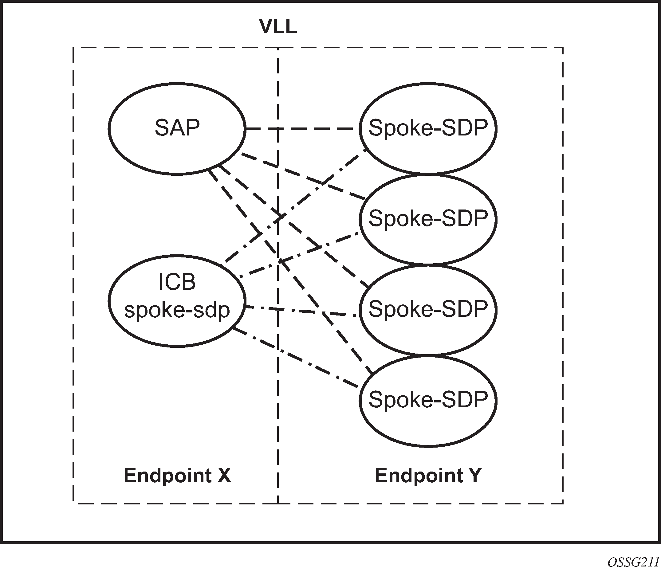
By default, a VLL service supports two implicit endpoints managed internally by the system. Each endpoint can only have one object: a SAP or a spoke-SDP.
To add more objects, up to two explicitly named endpoints may be created per VLL service. The endpoint name is locally significant to the VLL service. They are referred to as endpoint X and endpoint Y, as shown in the example in Redundant VLL endpoint objects.
In Redundant VLL endpoint objects, the Y endpoint can also have a SAP and, or an ICB spoke-SDP. The following is a list of supported endpoint objects and the applicable rules to associate the object with an endpoint of a VLL service:
SAP
A maximum of one SAP per VLL endpoint is supported.
primary spoke-SDP
The VLL service always uses this pseudowire and only switches to a secondary pseudowire when this primary pseudowire is down; the VLL service switches the path to the primary pseudowire when it is back up. The user can configure a timer to delay reverting back to primary or to never revert. A maximum of one primary spoke-SDP per VLL endpoint is supported.
secondary spoke-SDP
There can be a maximum of four secondary spoke-SDPs per endpoint. The user can configure the precedence of a secondary pseudowire to indicate the order in which a secondary pseudowire is activated.
Inter-Chassis Backup (ICB) spoke-SDP
This special pseudowire is used for MC-LAG and pseudowire redundancy applications. Forwarding between ICBs is blocked on the same node. The user has to explicitly indicate that the spoke-SDP is an ICB, at creation time. However, following are a few scenarios where the user can configure the spoke-SDP as ICB or as a regular spoke-SDP on a specified node. The CLI for those cases indicates both options.
A VLL service endpoint can only use a single active object to transmit at a specific time, but it can receive from all endpoint objects.
An explicitly named endpoint can have a maximum of one SAP and one ICB. When a SAP is added to the endpoint, only one more object of type ICB spoke-SDP is allowed. The ICB spoke-SDP cannot be added to the endpoint if the SAP is not part of an MC-LAG instance. Conversely, a SAP that is not part of an MC-LAG instance cannot be added to an endpoint that already has an ICB spoke-SDP.
An explicitly named endpoint that does not have a SAP object can have a maximum of four spoke-SDPs and includes any of the following:
a single primary spoke-SDP
one or many secondary spoke-SDPs with precedence
a single ICB spoke-SDP
T-LDP status notification handling rules
Using Redundant VLL endpoint objects as a reference, this section describes the rules for generating, processing, and merging T-LDP status notifications in VLL service with endpoints. Any allowed combination of objects as specified in Redundant VLL service model, can be used on endpoints X and Y. The following sections see the specific combination objects in Redundant VLL endpoint objects as an example to describe the more general rules.
Processing endpoint SAP active/standby status bits
The advertised administrative forwarding status bit of active/standby reflects the status of the local LAG SAP in MC-LAG application. If the SAP is not part of an MC-LAG instance, the forwarding status of active is always advertised.
If the SAP in endpoint X is part of an MC-LAG instance, a node must send a T-LDP forwarding status bit of SAP active/standby over all Y endpoint spoke-SDPs, except the ICB spoke-SDP, whenever this status changes. The status bit sent over the ICB is always zero (active by default).
If the SAP in endpoint X is not part of an MC-LAG instance, then the forwarding status sent over all Y endpoint spoke-SDPs should always be set to zero (active by default).
Processing and merging
Endpoint X is operationally up if at least one of its objects is operationally up. It is down if all of its objects are operationally down.
If the SAP in endpoint X transitions locally to the down state or received a SAP down notification by the SAP-specific OAM signal, the node must send T-LDP SAP down status bits on the Y endpoint ICB spoke-SDP only. Ethernet SAP does not support SAP OAM protocol. All other SAP types cannot exist on the same endpoint as an ICB spoke-SDP because a non-Ethernet SAP cannot be part of an MC-LAG instance.
If the ICB spoke-SDP in endpoint X transitions locally to down state, the node must send T-LDP SDP-binding down status bits on this spoke-SDP.
If the ICB spoke-SDP in endpoint X receives T-LDP SDP-binding down status bits or pseudowire not forwarding status bits, the node saves this status and takes no further action. The saved status is used for active transmit endpoint object selection.
If all objects in endpoint X perform any or all of the following operations, the node must send status bits of SAP down over all ‟Y” endpoint spoke-SDPs, including the ICB:
transitioned locally to down state
received a SAP down notification by remote T-LDP status bits or by SAP-specific OAM signal
received SDP-binding down status bits
received PW not forwarding status bits
Endpoint Y is operationally up if at least one of its objects is operationally up. It is down if all its objects are operationally down.
If a spoke-SDP in endpoint Y, including the ICB spoke-SDP, transitions locally to down state, the node must send T-LDP SDP-binding down status bits on this spoke-SDP.
If a spoke-SDP in endpoint Y, including the ICB spoke-SDP, performed any or all of the following operations, the node saves this status and takes no further action:
received T-LDP SAP down status bits
received T-LDP SDP-binding down status bits
received PW not forwarding status bits
The saved status is used for selecting the active transmit endpoint object.
If all objects in endpoint Y, except the ICB spoke-SDP, performed any or all of the following operations, the node must send status bits of SDP-binding down over the X endpoint ICB spoke-SDP only:
transitioned locally to the down state
received T-LDP SAP down status bits
received T-LDP SDP-binding down status bits
received PW not forwarding status bits
If all objects in endpoint Y performed any or all of the following operations, he node must send status bits of SDP-binding down over the X endpoint ICB spoke-SDP, and must send a SAP down notification on the X endpoint SAP by the SAP-specific OAM signal if applicable:
transitioned locally to down state
received T-LDP SAP down status bits
received T-LDP SDP-binding down status bits
received PW not forwarding status bits
An Ethernet SAP does not support signaling status notifications.
MC-APS and MC-LAG
In many cases, 7750 SRs are deployed in redundant pairs at the MSC. HSDPA off load fallback with MC-APS shows this case, assuming that MC-APS is deployed on the RNC connection. For MC-APS to be used, clear channel SONET or SDH connections should be used.

In this scenario, endpoint Y allows an ICB spoke-SDP as well as the primary spoke-SDP and secondary SAP. ICB operation is maintained as the current redundant pseudowire operation and the ICB spoke-SDP is always provided an active status. The ICB spoke-SDP is only used if both the primary spoke-SDP and secondary SAP are not available. The secondary SAP is used if it is operationally up and the primary spoke-SDP pseudowire status is not active. Receive is enabled on all objects even though transmit is only enabled on one.
To allow correct operation in all failure scenarios, an ICB spoke-SDP must be added to endpoint X. The ICB spoke-SDP is only used if the SAP is operationally down.
The following is an example configuration of Epipes mapping to HSDPA off load fallback with MC-APS. A SAP can be added to an endpoint with a non-ICB spoke-SDP only if the precedence of the spoke is primary.
7750 SR #1
*A:ALA-A>config>service#  epipe 1
----------------------------------------------
            endpoint X
            exit
            endpoint Y
            exit
            sap 1/1/2:0 endpoint X
              exit
            spoke-sdp 1:100 endpoint X icb
              exit
            spoke-sdp 10:500 endpoint Y
              precedence primary
              exit
            sap 1/1/3:0 endpoint Y
            exit
            spoke-sdp 1:200 endpoint Y icb
            exit
----------------------------------------------
*A:ALA-A>config>service#
7750 SR #2
*A:ALA-B>config>service# epipe 1
----------------------------------------------
            endpoint X
            exit
            endpoint Y
            exit
            sap 2/3/4:0 endpoint X
            exit
            spoke-sdp 1:200 endpoint X icb
            exit
            spoke-sdp 20:600 endpoint Y
              precedence primary
              exit
            sap 2/3/5:0 endpoint Y
            exit
            spoke-sdp 1:100 endpoint Y icb
            exit
----------------------------------------------
*A:ALA-B>config>service#
Failure scenario
Based on the previously mentioned rules, the following is an example of a failure scenario. Assuming both links are active on 7750 SR #1 and the Ethernet connection to the cell site fails (most likely failure scenario because the connection would not be protected), SDP1 would go down and the secondary SAP would be used in 7750 SR #1 and 7705 SAR, as shown in Ethernet failure at cell site.
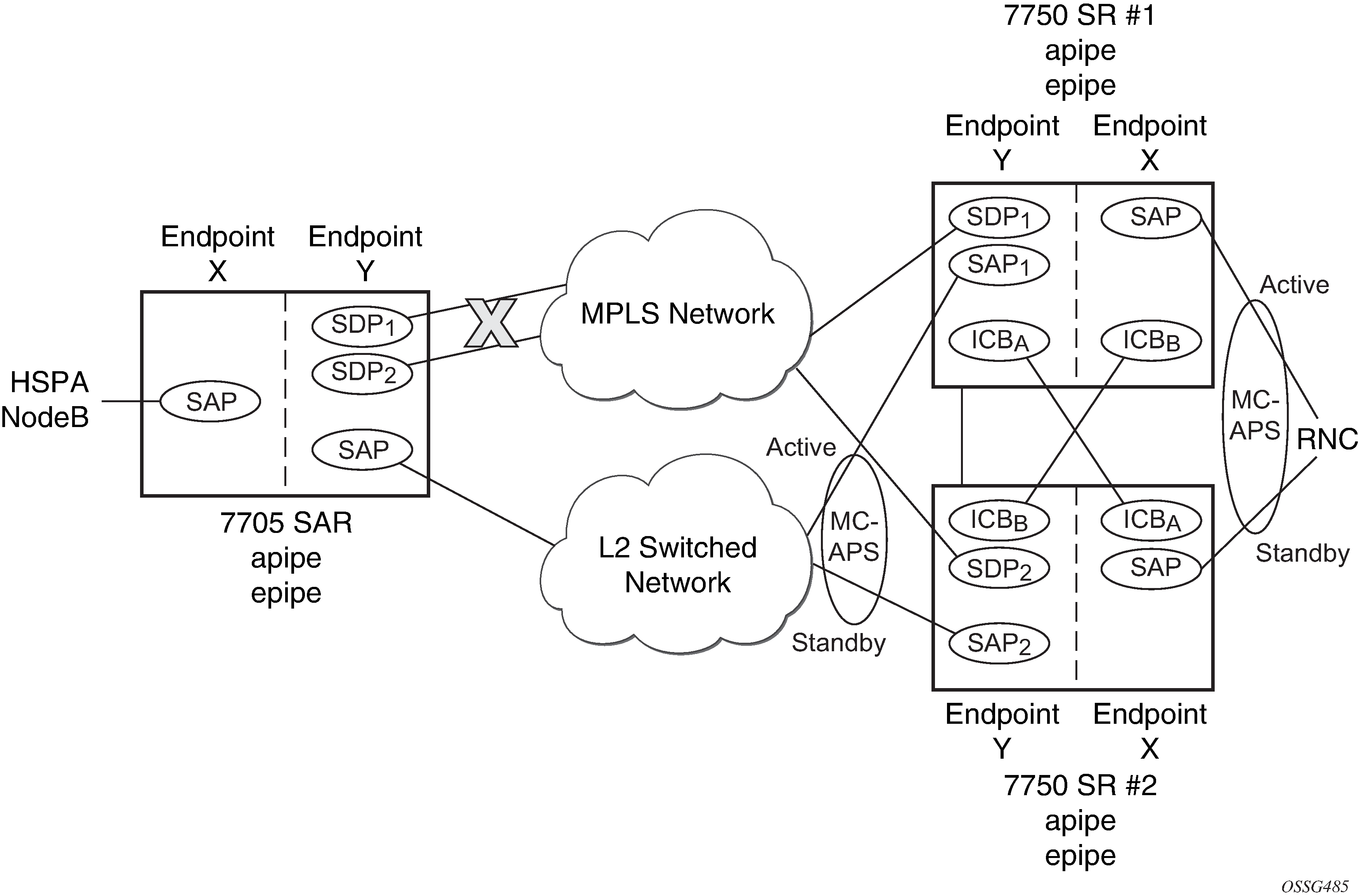
If the active link to the Layer 2 switched network was on 7750 SR #2 at the time of the failure, SAP1 would be operationally down (because the link is in standby) and ICBA would be used. Because the RNC SAP on 7750 SR #2 is on a standby APS link, ICBA would be active and it would connect to SAP2 because SDP2 is operationally down as well.
All APS link failures would be handled through the standard pseudowire status messaging procedures for the RNC connection and through standard ICB usage for the Layer 2 switched network connection.
VLL using G.8031 protected Ethernet tunnels
The use of MPLS tunnels provides the 7450 ESS and 7750 SR OS a way to scale the core while offering fast failover times using MPLS FRR. In environments where Ethernet services are deployed using native Ethernet backbones, Ethernet tunnels are provided to achieve the same fast failover times as in the MPLS FRR case.
The Nokia VLL implementation offers the capability to use core Ethernet tunnels compliant with ITU-T G.8031 specification to achieve 50 ms resiliency for backbone failures. This is required to comply with the stringent SLAs provided by service providers. Epipe and Ipipe services are supported.
When using Ethernet tunnels, the Ethernet tunnel logical interface is created first. The Ethernet tunnel has member ports, which are the physical ports supporting the links. The Ethernet tunnel control SAPs carry G.8031 and 802.1ag control traffic and user data traffic. Ethernet service SAPs are configured on the Ethernet tunnel. Optionally, when tunnels follow the same paths, end-to-end services may be configured with fate shared Ethernet tunnel SAPs, which carry only user data traffic and share the fate of the Ethernet tunnel port (if correctly configured).
Ethernet tunnels provide a logical interface that VLL SAPs may use just as regular interfaces. The Ethernet tunnel provides resiliency by providing end-to-end tunnels. The tunnels are stitched together by VPLS or Epipe services at intermediate points. Epipes offer a more scalable option.
For further information, see the 7450 ESS, 7750 SR, 7950 XRS, and VSR Services Overview Guide.
MPLS entropy label and hash label
The router supports the MPLS entropy label (RFC 6790) and the Flow Aware Transport label, known as the hash label (RFC 6391). LSR nodes in a network can load-balance labeled packets in a more granular way than by hashing on the standard label stack. See the 7450 ESS, 7750 SR, 7950 XRS, and VSR MPLS Guide for more information.
The entropy label is supported for Epipe and Ipipe VLL services as well as BGP VPWS. To configure insertion of the entropy label on a spoke-SDP of a specific service, use the entropy-label command in the spoke-sdp or pw-template context. Note that the entropy label is only inserted if the far end of the MPLS tunnel is also entropy-label-capable.
configure service epipe spoke-sdp hash-labelconfigure service ipipe spoke-sdp hash-labelconfigure service pw-template hash-labelEither the hash label or the entropy label can be configured on one object, but not both.
BGP VPWS
BGP Virtual Private Wire Service (VPWS) is a point-to-point Layer 2 VPN service based on RFC 6624 Layer 2 Virtual Private Networks using BGP for Auto-Discovery and Signaling, which in turn uses the BGP pseudowire signaling concepts described in RFC 4761, Virtual Private LAN Service Using BGP for Auto-Discovery and Signaling.
The BGP-signaled pseudowires created can use either automatic or preprovisioned SDPs over LDP- or BGP-signaled tunnels; the choice of tunnel depends on the tunnel's preference in the tunnel table, or over GRE. Preprovisioned SDPs must be configured when RSVP signaled transport tunnels are used.
The use of an automatically created GRE tunnel is enabled by creating the PW template used within the service with the parameter auto-gre-sdp. The GRE SDP and SDP binding are created after a matching BGP route is received.
Inter-AS model C and dual-homing are supported.
Single-homed BGP VPWS
A single-homed BGP VPWS service is implemented as an Epipe connecting a SAP or static GRE tunnel (a spoke-SDP using a GRE SDP configured with static MPLS labels) and a BGP signaled pseudowire, maintaining the Epipe properties such as no MAC learning. The MPLS pseudowire data plane uses a two-label stack; the inner label is derived from the BGP signaling and identifies the Epipe service while the outer label is the tunnel label of an LSP transporting the traffic between the two end systems.
The following figures shows how this service would be used to provide a virtual leased line service (VLL) across an MPLS network between sites A and B.
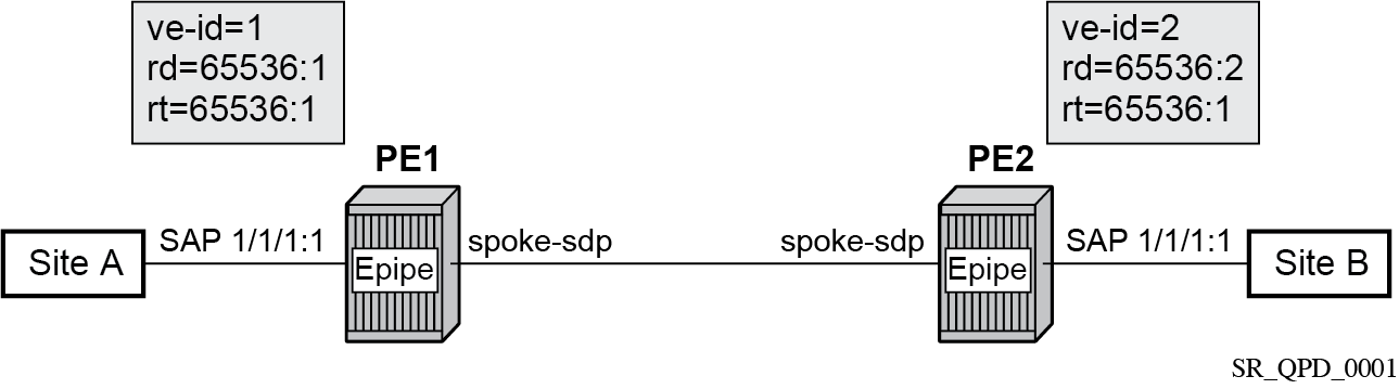
An Epipe is configured on PE1 and PE2 with BGP VPWS enabled. PE1 and PE2 are connected to site A and B, respectively, each using a SAP. The interconnection between the two PEs is achieved through a pseudowire that is signaled using BGP VPWS updates over a specific tunnel LSP.
Dual-homed BGP VPWS
A BGP-VPWS service can benefit from dual-homing, as described in IETF Draft draft-ietf-bess-vpls-multihoming-01. When using dual-homing, two PEs connect to a site, with one PE being the DF for the site and the other blocking its connection to the site. On failure of the active PE, its pseudowire, or its connection to the site, the other PE becomes the designated forwarder and unblocks its connection to the site.
Single pseudowire example
A pseudowire is established between the designated forwarder of the dual-homed PEs and the remote PE. If a failure causes a change in the designated forwarder, the pseudowire is deleted and reestablished between the remote PE and the new designated forwarder. This topology requires that the VE IDs on the dual-homed PEs are set to the same value.
The following figure shows a dual-homed, single pseudowire topology example.
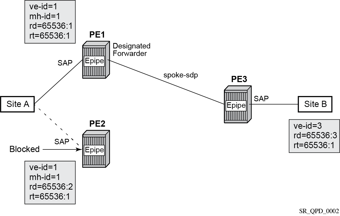
An Epipe with BGP VPWS enabled is configured on each PE. Site A is dual-homed to PE1 and PE2 with the remote PE (PE3) connecting to site B. An Epipe service is configured on each PE in which there is a SAP connecting to the local site.
The pair of dual-homed PEs perform a designated forwarder election, which is influenced by BGP route selection, the site state, and configuration of the site-preference. A site is only eligible to be the designated forwarder if it is up (the site state is down if there is no pseudowire established or if the pseudowire is in an operationally down state). The winner, for example PE1, becomes the active switch for traffic sent to and from site A, while the loser blocks its connection to site A.
Pseudowires are signaled using BGP from PE1 and PE2 to PE3, but only from PE3 to the designated forwarder in the opposite direction (so only one bidirectional pseudowire is established). There is no pseudowire between PE1 and PE2; this is achieved by configuration.
Traffic is sent and received traffic on the pseudowire connected between PE3 and the designated forwarder, PE1.
If the site state is operationally down, both the D and Circuit Status Vector (CSV) bits (see the following for more details) are set in the BGP-VPWS update, which causes the remote PE to use the pseudowire to the new designated forwarder.
Active/standby pseudowire example
Pseudowires are established between the remote PE and each dual-homed PE. The remote PE can receive traffic on either pseudowire, but only sends on the one to the designated forwarder. This creates an active/standby pair of pseudowires. At most, one standby pseudowire is established; this being determined using the tie-breaking rules defined in the multihoming draft. This topology requires each PE to have a different VE ID.
The following figure shows an example of a dual-homed, active/standby pseudowires topology.
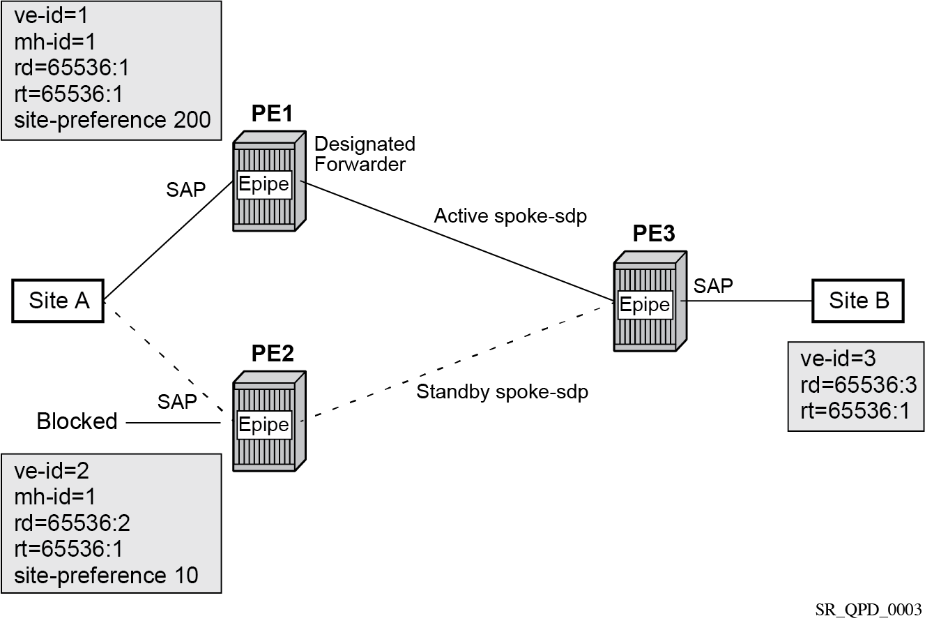
An Epipe with BGP VPWS enabled is configured on each PE. Site A is dual-homed to PE1 and PE2 with the remote PE (PE3) connecting to site B. An Epipe service is configured on each PE in which there is a SAP connecting to the local site.
The pair of dual-homed PEs perform a designated forwarder election, which is influenced by configuring the site-preference value. The winner, PE1 (based on its higher site-preference value) becomes the active switch for traffic sent to and from site A, while the loser, PE2, blocks its connection to site A. Pseudowires are signaled using BGP between PE1 and PE3, and between PE2 and PE3. There is no pseudowire between PE1 and PE2; this is achieved by configuration. The active/standby pseudowires on PE3 are part of an endpoint automatically created in the Epipe service.
Traffic is sent and received on the pseudowire connected to the designated forwarder, PE1.
BGP VPWS pseudowire switching
Pseudowire switching is supported with a BGP VPWS service allowing the cross connection between a BGP VPWS signaled spoke-SDP and a static GRE tunnel, the latter being a spoke SDP configured with static MPLS labels using a GRE SDP. No other spoke SDP types are supported. Support is not included for BGP multihoming using an active and a standby pseudowire to a pair of remote PEs.
Operational state changes to the GRE tunnel are reflected in the state of the Epipe and propagated accordingly in the BGP VPWS spoke SDP status signaling, specifically using the BGP update D and CSV bits.
The following configuration is required:
The Epipe service must be created using the vc-switching parameter.
The GRE tunnel spoke SDP must be configured using a GRE SDP with signaling off and have the ingress and egress vc-labels statically configured.
Example: BGP VPWS service configured to allow pseudowire switching
configure
    service
        sdp 1 create
            signaling off
            far-end 192.168.1.1
            keep-alive
                shutdown
            exit
            no shutdown
        exit
        pw-template 1 create
        exit
        epipe 1 customer 1 vc-switching create
            description "BGP VPWS service"
            bgp
                route-distinguisher 65536:1
                route-target export target:65536:1 import target:65536:1
                pw-template-binding 1
                exit
            exit
            bgp-vpws
                ve-name "PE1"
                    ve-id 1
                exit
                remote-ve-name "PE2"
                    ve-id 2
                exit
                no shutdown
            exit
            spoke-sdp 1:1 create
                ingress
                    vc-label 1111
                exit
                egress
                    vc-label 1122
                exit
                no shutdown
            exit
            no shutdown
        exit
Pseudowire signaling
The BGP signaling mechanism used to establish the pseudowires is described in the BGP VPWS standards with the following differences:
As stated in Section 3 of RFC 6624, there are two modifications of messages when compared to RFC 4761:
the Encaps Types supported in the associated extended community
the addition of a circuit status vector sub-TLV at the end of the VPWS NLRI
The control flags and VPLS preference in the associated extended community are based on IETF Draft draft-ietf-bess-vpls-multihoming-01.
The following figure shows the format of the BGP VPWS update extended community.
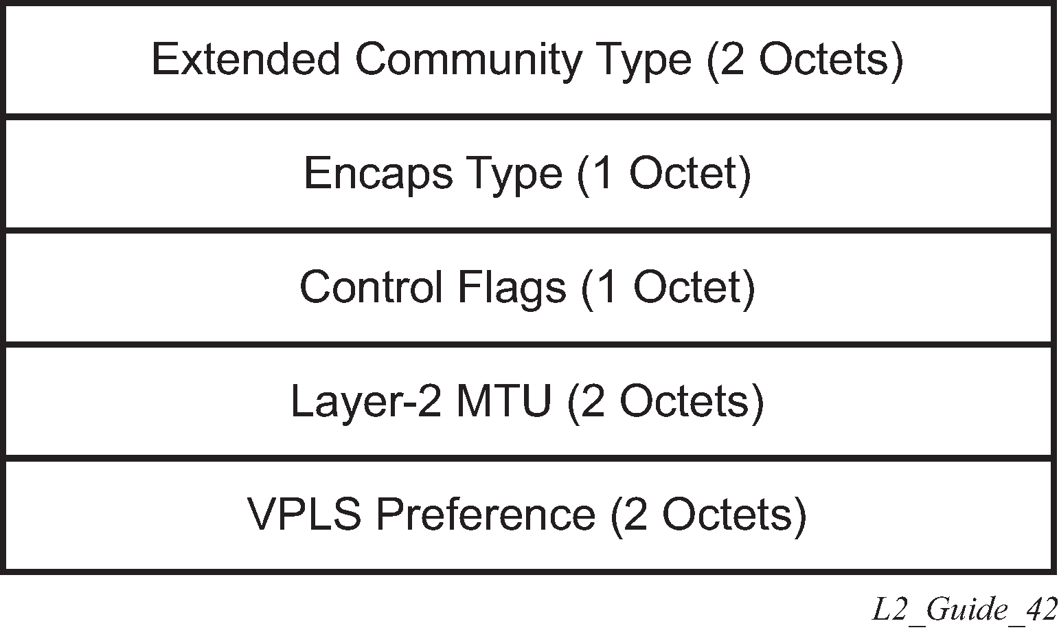
extended community type
This is the value allocated by IANA for this attribute is 0x800A.
encaps type
The encapsulation type identifies the type of pseudowire encapsulation. Ethernet VLAN (4) and Ethernet Raw mode (5), as described in RFC 4448, are the only values supported. If there is a mismatch between the Encaps Type signaled and the one received, the pseudowire is created but with the operationally down state.
control flags
This is control information concerning the pseudowires, see Control flags for more information.
Layer 2 MTU
This is the MTU to be used on the pseudowires. If the received Layer 2 MTU is zero, no MTU check is performed and the related pseudowire is established. If there is a mismatch between the local service-mtu and the received Layer 2 MTU, the pseudowire is created with the operationally down state and an MTU/Parameter mismatch indication.
VPLS preference
VPLS preference has a default value of zero for BGP-VPWS updates sent by the system, indicating that it is not in use. If site-preference is configured, its value is used for the VPLS preference and is also used in the local designated forwarder election.
On receipt of a BGP VPWS update containing a non-zero value, it is used to determine to which system the pseudowire is established, as part of the VPWS update process tie-breaking rules. The BGP local preference of the BGP VPWS update sent by the system is set to the same value as the VPLS preference if the latter is non-zero, as required by the draft (as long as the D bit in the extended community is not set to 1). Consequently, attempts to change the BGP local preference when exporting a BGP VPWS update with a non-zero VPLS preference is ignored. This prevents the updates being treated as malformed by the receiver of the update.
For inter-AS, the preference information must be propagated between autonomous systems using the VPLS preference. Consequently, if the VPLS preference in a BGP-VPWS or BGP multihoming update is zero, the local preference is copied by the egress ASBR into the VPLS preference field before sending the update to the External Border Gateway Protocol (EBGP) peer. The adjacent ingress ASBR then copies the received VPLS preference into the local preference to prevent the update from being considered malformed.
The following figure shows the pseudowire control flags.

The following bits in the Control Flags are defined:
- D
- Access circuit down indicator from IETF Draft draft-kothari-l2vpn-auto-site-id-01. D is 1 if all access circuits are down, otherwise D is 0.
- A
- Automatic site ID allocation, which is not supported. This is ignored on receipt and set to 0 on sending.
- F
- MAC flush indicator. This is not supported because it relates to a VPLS service. This is set to 0 and ignored on receipt.
- C
- Presence of a control word. Control word usage is supported. When this is set to 1, packets are sent and are expected to be received, with a control word. When this is set to 0, packets are sent and are expected to be received without a control word (by default).
- S
- Sequenced delivery. Sequenced delivery is not supported. This is set to 0 on sending (no sequenced delivery) and, if a non-zero value is received (indicating sequenced delivery required), the pseudowire is not created.
The BGP VPWS NLRI is based on that defined for BGP VPLS, but is extended with a circuit status vector as shown in the following figure.
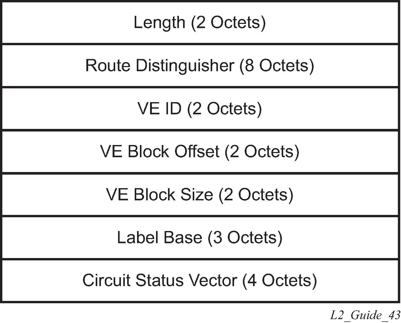
The VE ID value is configured within each BGP VPWS service, the label base is chosen by the system, and the VE block offset corresponds to the remote VE ID because a VE block size of 1 is always used.
The circuit status vector is encoded as a TLV, as shown in BGP VPWS NLRI TLV extension format and Circuit status vector TLV type.
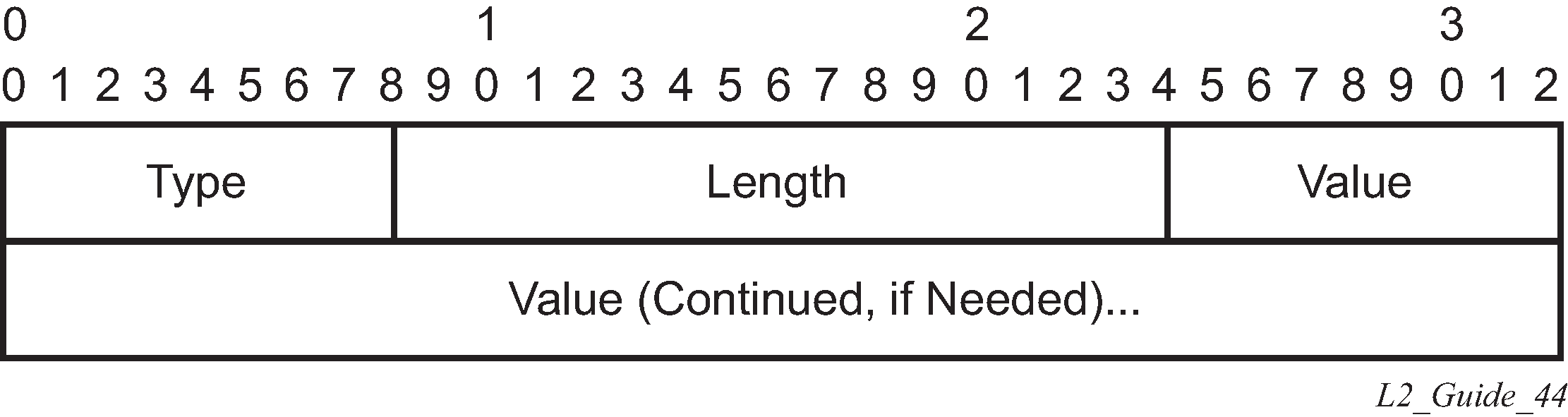

The circuit status vector is used to indicate the status of both the SAP/GRE tunnel and the status of the spoke-SDP within the local service. Because the VE block size used is 1, the most significant bit in the circuit status vector TLV value is set to 1 if either the SAP/GRE tunnel or spoke-SDP is down, otherwise it is set to 0. On receiving a circuit status vector, only the most significant byte of the CSV is examined for designated forwarder selection purposes.
If a circuit status vector length field of greater than 32 is received, the update is ignored and not reflected to BGP neighbors. If the length field is greater than 800, a notification message is sent and the BGP session restarts. Also, BGP VPWS services support a single access circuit, so only the most significant bit of the CSV is examined on receipt.
A pseudowire is established when a BGP VPWS update is received that matches the service configuration, specifically the configured route targets and remote VE ID. If multiple matching updates are received, the system to which the pseudowire is established is determined by the tie-breaking rules, as described in IETF Draft draft-ietf-bess-vpls-multihoming-01.
Traffic is sent on the active pseudowire connected to the remote designated forwarder. Traffic can be received on either the active or standby pseudowire, although no traffic should be received on the standby pseudowire because the SAP/GRE tunnel on the non-designated forwarder should be blocked.
The adv-service-mtu command can be used to override the MTU value used in BGP signaling to the far-end of the pseudowire. This value is also used to validate the value signaled by the far-end PE unless ignore-l2vpn-mtu-mismatch is also configured.
If the ignore-l2vpn-mtu-mismatch command is configured, the router does not check the value of the "Layer 2 MTU" in the "Layer2 Info Extended Community" received in a BGP update message against the local service MTU, or against the MTU value signaled by this router. The router brings up the BGP-VPWS service regardless of any MTU mismatch.
BGP-VPWS with inter-AS model C
BGP VPWS with inter-AS model C is supported both in a single-homed and dual-homed configuration.
When dual-homing is used, the dual-homed PEs must have different values configured for the site-preference (under the site within the Epipe service) to allow the PEs in a different AS to select the designated forwarder when all access circuits are up. The value configured for the site-preference is propagated between autonomous systems in the BGP VPWS and BGP multihoming update extended community VPLS preference field. The receiving ingress ASBR copies the VPLS preference value into local preference of the update to ensure that the VPLS preference and local preference are equal, which prevents the update from being considered malformed.
BGP VPWS configuration procedure
In addition to configuring the associated BGP and MPLS infrastructure, the provisioning of a BGP VPWS service requires:
-
configuring the BGP Route Distinguisher, Route Target
The updates are accepted into the service only if they contain the configured import route-target.
-
configuring a binding to the pseudowire template
The multiple pseudowire template bindings can be configured with their associated route-targets used to control which is applied.
configuring the SAP or static GRE tunnel
configuring the name of the local VE and its associate VE ID
configuring the name of the remote VE and its associated VE ID
for a dual-homed PE:
enabling the site
configuring the site with non-zero site-preference
-
for a remote PE, configure up to two remote VE names and associated VE IDs
enabling BGP VPWS
Use of pseudowire template for BGP VPWS
The pseudowire template concept used for BGP AD is reused for BGP VPWS to dynamically instantiate pseudowires (SDP-bindings) and the related SDPs (provisioned or automatically instantiated).
The settings for the L2-Info extended community in the BGP update sent by the system are derived from the pw-template attributes. The following rules apply:
If multiple pw-template-bindings (with or without import-rt) are specified for the VPWS instance, the first (numerically lowest ID) pw-template entry is used.
Both Ethernet VLAN and Ethernet Raw Mode Encaps Types are supported; these are selected by configuring the vc-type in the pseudowire template to be either vlan or ether, respectively. The default is ether.
The same value must be used by the remote BGP VPWS instance to ensure that the related pseudowire comes up.Layer 2 MTU is derived from the service VPLS service-mtu parameter.
The same value must be used by the remote BGP VPWS instance to ensure that the related pseudowire comes up.Control Flag C can be 0 or 1, depending on the setting of the controlword parameter in the PW template 0.
Control Flag S is always 0.
On reception, the values of the parameters in the L2-Info extended community of the BGP update are compared with the settings from the corresponding pw-template. The following steps are used to determine the local pw-template:
The route-target values are matched to determine the pw-template. The binding configured with the first matching route target is chosen.
If a match is not found from the previous step, the lowest pw-template-binding (numerically) without any route-target configured is used.
If the values used for encap-type or Layer 2 MTU do not match, the pseudowire is created but with the operationally down state.
To interoperate with existing implementations, if the received MTU value = 0, the MTU negotiation does not take place; the related pseudowire is set up ignoring the MTU.If the value of the S flag is not zero, the pseudowire is not created.
The following pseudowire template parameters are supported when applied within a BGP VPWS service; the remainder are ignored:
configure service pw-template policy-id [use-provisioned-sdp |
       [prefer-provisioned-sdp] [auto-sdp]] [create] [name name]
   accounting-policy acct-policy-id
   no accounting-policy
   [no] collect-stats
   [no] controlword
   egress
      filter ipv6 ipv6-filter-id
      filter ip ip-filter-id
      filter mac mac-filter-id
      no filter [ip ip-filter-id] [mac mac-filter-id] [ipv6 ipv6-filter-id]
      qos network-policy-id port-redirect-group queue-group-name instance instance
id
      no qos [network-policy-id]
   [no] force-vlan-vc-forwarding
   hash-label [signal-capability]
   no hash-label
   ingress
      filter ipv6 ipv6-filter-id
      filter ip ip-filter-id
      filter mac mac-filter-id
      no filter [ip ip-filter-id] [mac mac-filter-id] [ipv6 ipv6-filter-id]
      qos network-policy-id fp-redirect-group queue-group-name instance instance-id
      no qos [network-policy-id]
   [no] sdp-exclude
   [no] sdp-include
   vc-type {ether | vlan}
   vlan-vc-tag vlan-id
   no vlan-vc-tag
For more information about this command, see the 7450 ESS, 7750 SR, 7950 XRS, and VSR Services Overview Guide.
The use-provisioned-sdp option is permitted when creating the pseudowire template if a preprovisioned SDP is to be used. Preprovisioned SDPs must be configured whenever RSVP-signaled transport tunnels are used.
When the prefer-provisioned-sdp option is specified, if the system finds an existing matching SDP that conforms to any restrictions defined in the pseudowire template (for example, sdp-include or sdp-exclude group), it uses this matching SDP (even if the existing SDP is operationally down); otherwise, it automatically creates an SDP.
When the auto-gre-sdp option is specified, a GRE SDP is automatically created.
The tools perform command can be used in the same way as for BGP-AD to apply changes to the pseudowire template using the following format:
tools perform service [id service-id] eval-pw-template policy-id [allow-service-impact]
If a user configures a service using a pseudowire template with the prefer-provisioned-sdp option, but without provisioning an applicable SDP and the system binds to an automatic SDP, and the user subsequently provisions an appropriate SDP, the system does not automatically switch to the new provisioned SDP. This only occurs if the pseudowire template is reevaluated using the tools perform service id service-id eval-pw-template command.
Use of endpoint for BGP VPWS
An endpoint is required on a remote PE connecting to two dual-homed PEs to associate the active/standby pseudowires with the Epipe service. An endpoint is automatically created within the Epipe service such that active/standby pseudowires are associated with that endpoint. The creation of the endpoint occurs when bgp-vpws is enabled (and deleted when it is disabled) and so exists in both a single- and dual-homed scenario. This simplifies converting a single-homed service to a dual-homed service. The naming convention used is _tmnx_BgpVpws-x, where x is the service identifier. The automatically created endpoint has the default parameter values, although all are ignored in a BGP-VPWS service with the description field being defined by the system.
The following command does not have any effect on an automatically created VPWS endpoint:
tools perform service id <service-id> endpoint <endpoint-name> force-switchover
VLL service considerations
This section describes the general 7450 ESS, 7750 SR, and 7950 XRS service features and any special capabilities or considerations as they relate to VLL services.
SDPs
The most basic SDPs must have the following:
A locally unique SDP identification (ID) number.
The system IP address of the originating and far-end routers.
An SDP encapsulation type, either GRE or MPLS.
SDP statistics for VPLS and VLL services
The three-node network in SDP statistics for VPLS and VLL services shows two MPLS SDPs and one GRE SDP defined between the nodes. These SDPs connect VPLS1 and VPLS2 instances that are defined in the three nodes. With this feature, the operator has local CLI-based and SNMP-based statistics collection for each VC used in the SDPs. This allows for traffic management of tunnel usage by the different services and with aggregation the total tunnel usage.
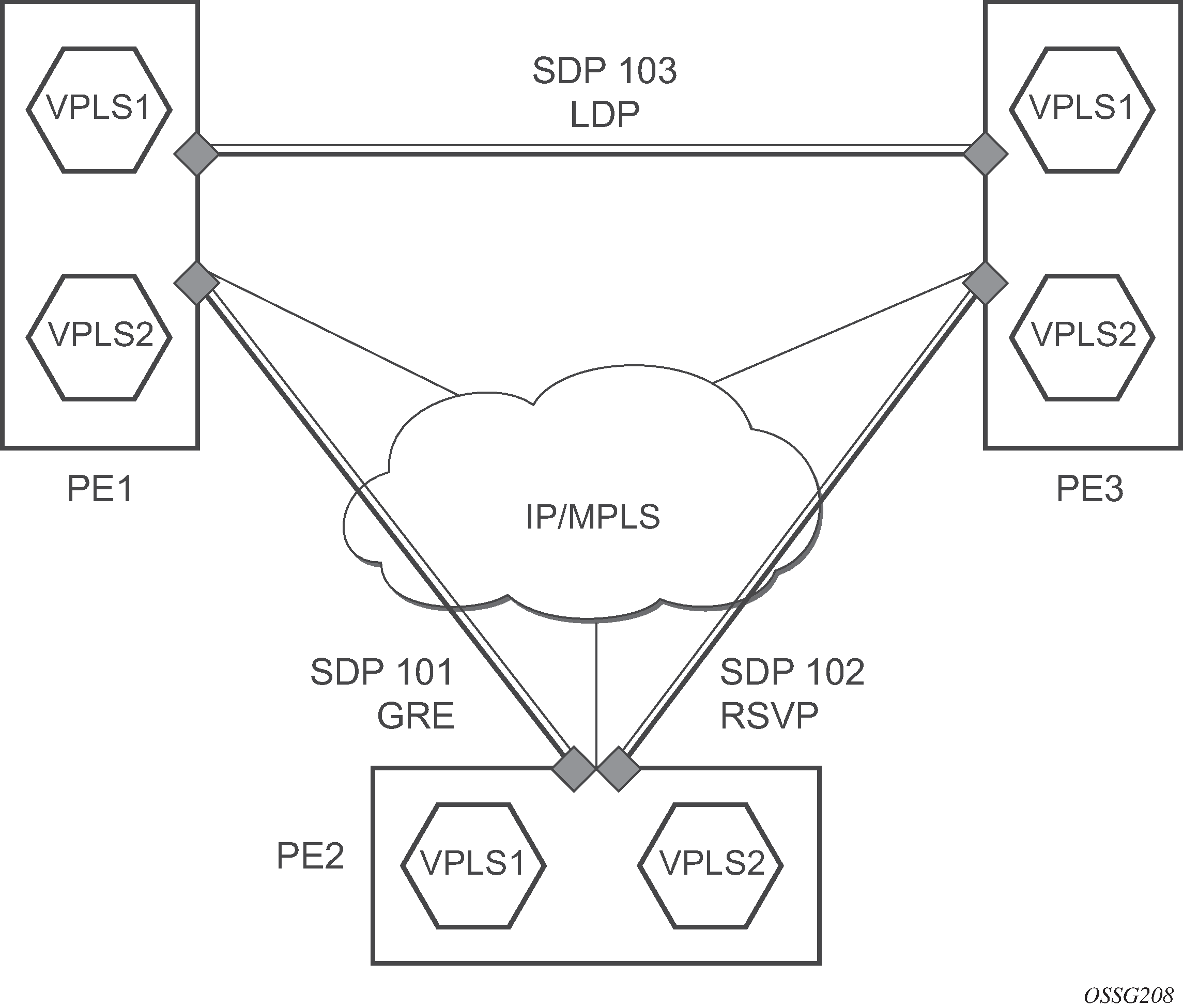
SAP encapsulations and pseudowire types
The Epipe service is designed to carry Ethernet frame payloads, so it can provide connectivity between any two SAPs that pass Ethernet frames. The following SAP encapsulations are supported on the 7450 ESS, 7750 SR, and 7950 XRS Epipe service:
Ethernet null
Ethernet dot1q
QinQ
SONET/SDH BCP-null for the 7450 ESS and 7750 SR
SONET/SDH BCP-dot1q for the 7450 ESS and 7750 SR
While different encapsulation types can be used, encapsulation mismatching can occur if the encapsulation behavior is not understood by connecting devices, which are unable to send and receive the expected traffic. For example, if the encapsulation type on one side of the Epipe is dot1q and the other is null, tagged traffic received on the null SAP is double-tagged when it is transmitted out of the dot1q SAP.
One pseudowire encapsulation mode, that is, SDP vc-type, is available: PWE3 N-to-1 Cell Mode Encapsulation.
QoS policies
When applied to 7450 ESS, 7750 SR, or 7950 XRS Epipe services, service ingress QoS policies only create the unicast queues defined in the policy. The multipoint queues are not created on the service.
With Epipe services, egress QoS policies function as with other services where the class-based queues are created as defined in the policy. Both Layer 2 or Layer 3 criteria can be used in the QoS policies for traffic classification in a service.
Filter policies
7450 ESS, 7750 SR, and 7950 XRS Epipe and Ipipe services can have a single filter policy associated on both ingress and egress. Both MAC and IP filter policies can be used on Epipe services.
MAC resources
Epipe services are point-to-point Layer 2 VPNs capable of carrying any Ethernet payloads. Although an Epipe is a Layer 2 service, the 7450 ESS, 7750 SR, and 7950 XRS Epipe implementation does not perform any MAC learning on the service, so Epipe services do not consume any MAC hardware resources.
Configuring a VLL service with CLI
This section provides information to configure Virtual Leased Line (VLL) services using the command line interface.
Common configuration tasks
This section provides a brief overview of the tasks that must be performed and the CLI commands that must be executed to configure the VLL services:
Associate the service with a customer ID.
Optionally, define SAP parameters:
Select egress and ingress QoS and, or scheduler policies (configured in the config>qos context).
Select accounting policy (configured in the config>log context).
Define spoke-SDP parameters.
Enable the service.
Configuring VLL components
This section provides VLL configuration examples for the VLL services.
Creating a Cpipe service
Basic configuration
Use the following CLI syntax to create a Cpipe service on a 7750 SR. A route distinguisher must be defined in order for Cpipe to be operationally active.
CLI syntax:
config>service# cpipe service-id [customer customer-id] [vpn vpn-id] [vc-type {satop-e1 | satop-t1 | cesopsn | cesopsn-cas}] [vc-switching] [create]
For the 7450 ESS platforms, the vc-switching option must be configured for Cpipe functionality, as follows:
cpipe 1 name "XYZ Cpipe 1" customer 1 vc-switching vc-type cesopsn create
            spoke-sdp 20:1 create
                description "Description for Sdp Bind 20 for Svc ID 1"
                ingress
                    vc-label 10002
                exit
                egress
                    vc-label 10001
                exit
            exit
            spoke-sdp 50:1 create
                description "Description for Sdp Bind 50 for Svc ID 1"
            exit
            no shutdown
        exit
The following displays a Cpipe service configuration example:
*A:ALA-1>config>service# info
----------------------------------------------
...
        cpipe 210 customer 1 vc-type cesopsn create
            service-mtu 1400
            sap 1/5/10.1.3.1 create
            exit
            spoke-sdp 1:210 create
            exit
            no shutdown
        exit
...
----------------------------------------------
*A:ALA-1>config>service#
Configuration requirements
Before a Cpipe service can be provisioned, a DS1 port and channel group must be configured. The subsequent sections provide example configurations for both.
Configuring a DS1 port
The following example shows a DS1 port configured for CES:
A:sim216#  show port 1/5/10.1.3.1
===============================================================================
TDM DS1 Interface
===============================================================================
Description        : DS1
Interface          : 1/5/10.1.3,1
Type               : ds1                     Framing              : esf
Admin Status       : up                      Oper Status          : up
Physical Link      : yes                     Clock Source         : loop-timed
Signal Mode        : none
Last State Change  : 10/31/2006 14:23:12     Channel IfIndex      : 580943939
Loopback           : none                    Invert Data          : false
Remote Loop respond: false                   In Remote Loop       : false
Load-balance-algo  : default                 Egr. Sched. Pol      : n/a
BERT Duration      : N/A                     BERT Pattern         : none
BERT Synched       : 00h00m00s               Err Insertion Rate   : 0
BERT Errors        : 0                       BERT Status          : idle
BERT Total Bits    : 0
Cfg Alarm          : ais los
Alarm Status       :
===============================================================================
A:sim216#
Configuring a channel group
The following example shows a DS1 channel group configured for CES:
A:sim216#  show port 1/5/10.1.3.1
===============================================================================
TDM DS0 Chan Group
===============================================================================
Description        : DS0GRP
Interface          : 1/5/10.1.3.1
TimeSlots          : 1-12
Speed              : 64                      CRC                  : 16
Admin Status       : up                      Oper Status          : up
Last State Change  : 10/31/2006 14:23:12     Chan-Grp IfIndex     : 580943940
Configured mode    : access                  Encap Type           : cem
Admin MTU          : 4112                    Oper MTU             : 4112
Physical Link      : Yes                     Bundle Number        : none
Idle Cycle Flags   : flags                   Load-balance-algo    : default
Egr. Sched. Pol    : n/a
===============================================================================
A:sim216#
Configuring Cpipe SAPs and spoke-SDPs
The following examples show Cpipe SAP and spoke-SDP configurations:
*A:ALA-49>config>service# info
#--------------------------------------------------
echo "Service Configuration"
#--------------------------------------------------
...
        cpipe 100 customer 1 vc-type cesopsn create
            service-mtu 1400
            sap 1/5/10.1.1.1 create
            exit
            spoke-sdp 1:100 create
            exit
            no shutdown
        exit
        cpipe 200 customer 1 vc-type cesopsn-cas create
            sap 1/5/10.2.1.1 create
            exit
            sap 1/5/10.2.2.1 create
            exit
            no shutdown
        exit
        cpipe 210 customer 1 vc-type cesopsn-cas create
            service-mtu 1400
            sap 1/5/10.1.3.1 create
            exit
            spoke-sdp 1:210 create
            exit
            no shutdown
        exit
        cpipe 300 customer 1 vc-type cesopsn create
            sap 1/5/10.3.4.1 create
            exit
            sap 1/5/10.3.6.1 create
            exit
            no shutdown
        exit
        cpipe 400 customer 1 vc-type satop-e1 create
            sap 1/5/10.2.3.1 create
            exit
            spoke-sdp 1:400 create
            exit
            no shutdown
        exit
...
#--------------------------------------------------
*A:ALA-49>config>service#
A:sim213>config>service>cpipe# info
----------------------------------------------
            description "cpipe-100"
            sap 1/5/10.1.1.1 create
                cem
                    packet jitter-buffer 16 payload-size 384
                    report-alarm rpktloss
                    no report-alarm stray
                    rtp-header
                exit
            exit
            spoke-sdp 1:100 create
            exit
            no shutdown
----------------------------------------------
A:sim213>config>service>cpipe#
Creating an Epipe service
Use the following CLI syntax to create an Epipe service.
CLI syntax:
config>service# epipe service-id [customer customer-id] [vpn vpn-id] [vc-switching]
description description-string
no shutdown
The following example shows an Epipe configuration:
A:ALA-1>config>service# info
-------------------------------------------
...
        epipe 500 customer 5 vpn 500 create
            description "Local epipe service"
            no shutdown
        exit
-------------------------------------------
A:ALA-1>config>service#
Configuring Epipe SAP parameters
A default QoS policy is applied to each ingress and egress SAP. Additional QoS policies can be configured in the config>qos context. Filter policies are configured in the config>filter context and explicitly applied to a SAP. There are no default filter policies.
Use the following CLI syntax to create:
The following example shows a configuration for the 7950 XRS.
CLI syntax:
config>service# epipe service-id [customer customer-id]
    — sap sap-id [endpoint endpoint-name]
    — sap sap-id [no-endpoint]
        — accounting-policy policy-id
        — collect-stats
        — description description-string
        — no shutdown
        — egress
            — filter {ip ip-filter-name | mac mac-filter-name}
            — qos sap-egress-policy-id
            — scheduler-policy scheduler-policy-name
        — ingress
            — filter {ip ip-filter-name | mac mac-filter-name}
            — match-qinq-dot1p {top | bottom}
            — qos policy-id
            — scheduler-policy scheduler-policy-name
The following example shows a configuration for the 7450 ESS and 7750 SR.
CLI syntax:
config>service# epipe service-id [customer customer-id]
    — sap sap-id [endpoint endpoint-name]
    — sap sap-id [no-endpoint]
        — accounting-policy policy-id
        — collect-stats
        — description description-string
        — no shutdown
        — egress
            — filter {ip ip-filter-name | mac mac-filter-name}
            — qos sap-egress-policy-id
            — scheduler-policy scheduler-policy-name
        — ingress
            — filter {ip ip-filter-name | mac mac-filter-name}
            — match-qinq-dot1p {top | bottom}
            — qos policy-id [shared-queuing]
            — scheduler-policy scheduler-policy-name
Local Epipe SAPs
To configure a basic local Epipe service, enter the sap sap-id command twice with different port IDs in the same service configuration.
By default, QoS policy ID 1 is applied to ingress and egress service SAPs. Existing filter policies or other existing QoS policies can be associated with service SAPs on ingress and egress ports. Supported SAP types shows supported SAP types.
| Uplink type | Svc SAP type | Cust. VID | Access SAPs | Network SAPs |
|---|---|---|---|---|
L2 |
Null-star |
— |
Null, dot1q * |
Q.* |
L2 |
Dot1q |
— |
Dot1q |
Q.* |
L2 |
Dot1q-preserve |
— |
Dot1q (encap = X) |
Q1.Q2 (where Q2 = X) |
An existing scheduler policy can be applied to ingress and egress SAPs to be used by the SAP queues and, at egress only, policers. The schedulers comprising the policy are created when the scheduler policy is applied to the SAP. If any policers or orphaned queues (with a non-existent local scheduler defined) exist on a SAP and the policy application creates the required scheduler, the status on the queue becomes non-orphaned at this time.
Ingress and egress SAP parameters can be applied to local and distributed Epipe service SAPs.
The following example shows the SAP configurations for local Epipe service 500 on SAP 1/1/2 and SAP 1/1/3 on ALA-1:
A:ALA-1>config>service# epipe 500 customer 5 create
    config>service>epipe$ description "Local epipe service"
    config>service>epipe# sap 1/1/2:0 create
    config>service>epipe>sap? ingress
    config>service>epipe>sap>ingress# qos 20
    config>service>epipe>sap>ingress# filter ip 1
    config>service>epipe>sap>ingress# exit
    config>service>epipe>sap# egress
    config>service>epipe>sap>egress# qos 20
    config>service>epipe>sap>egress# scheduler-policy test1
    config>service>epipe>sap>egress# exit
    config>service>epipe>sap# no shutdown
    config>service>epipe>sap# exit

    config>service>epipe# sap 1/1/3:0 create
    config>service>epipe>sap# ingress
    config>service>epipe>sap>ingress# qos 555
    config>service>epipe>sap>ingress# filter ip 1
    config>service>epipe>sap>ingress# exit
    config>service>epipe>sap# egress
    config>service>epipe>sap>egress# qos 627
    config>service>epipe>sap>egress# scheduler-policy alpha
    config>service>epipe>sap>egress# exit
    config>service>epipe>sap# no shutdown
    config>service>epipe>sap# exit
The following example shows the local Epipe configuration:
A:ALA-1>config>service# info
----------------------------------------------
...
        epipe 500 customer 5 vpn 500 create
            description "Local epipe service"
            sap 1/1/2:0 create
                ingress
                    qos 20
                    filter ip 1
                exit
                egress
                    scheduler-policy "test1"
                    qos 20
                exit
            exit
            sap 1/1/3:0 create
                ingress
                    qos 555
                    filter ip 1
                exit
                egress
                    scheduler-policy "alpha"
                    qos 627
                exit
            exit
            no shutdown
        exit
----------------------------------------------
A:ALA-1>config>service#
Distributed Epipe SAPs
To configure a distributed Epipe service, you must configure service entities on the originating and far-end nodes. You should use the same service ID on both ends (for example, Epipe 5500 on ALA-1 and Epipe 5500 on ALA-2). The spoke-sdp sdp-id:vc-id must match on both sides. A distributed Epipe consists of two SAPs on different nodes.
By default, QoS policy ID 1 is applied to ingress and egress service SAPs. Existing filter policies or other existing QoS policies can be associated with service SAPs on ingress and egress.
An existing scheduler policy can be applied to ingress and egress SAPs to be used by the SAP queues and, at egress only, policers. The schedulers comprising the policy are created when the scheduler policy is applied to the SAP. If any policers or orphaned queues (with a non-existent local scheduler defined) exist on a SAP and the policy application creates the required scheduler, the status on the queue becomes non-orphaned at this time.
Ingress and egress SAP parameters can be applied to local and distributed Epipe service SAPs.
For SDP configuration information, see the 7450 ESS, 7750 SR, 7950 XRS, and VSR Services Overview Guide. For SDP binding information, see Configuring SDP bindings.
The following example shows a configuration of a distributed service between ALA-1 and ALA-2:
A:ALA-1>epipe 5500 customer 5 create
    config>service>epipe$ description "Distributed epipe service to east coast"
    config>service>epipe# sap 221/1/3:21 create
    config>service>epipe>sap# ingress
    config>service>epipe>sap>ingress# qos 555
    config>service>epipe>sap>ingress# filter ip 1
    config>service>epipe>sap>ingress# exit
    config>service>epipe>sap# egress
    config>service>epipe>sap>egress# qos 627
    config>service>epipe>sap>egress# scheduler-policy alpha
    config>service>epipe>sap>egress# exit
    config>service>epipe>sap# no shutdown
    config>service>epipe>sap# exit
    config>service>epipe#

A:ALA-2>config>service# epipe 5500 customer 5 create
    config>service>epipe$ description "Distributed epipe service to west coast"
    config>service>epipe# sap 441/1/4:550 create
    config>service>epipe>sap# ingress
    config>service>epipe>sap>ingress# qos 654
    config>service>epipe>sap>ingress# filter ip 1020
    config>service>epipe>sap>ingress# exit
    config>service>epipe>sap# egress
    config>service>epipe>sap>egress# qos 432
    config>service>epipe>sap>egress# filter ip 6
    config>service>epipe>sap>egress# scheduler-policy test1
    config>service>epipe>sap>egress# exit
    config>service>epipe>sap# no shutdown
    config>service>epipe#
The following example shows the SAP configurations for ALA-1 and ALA-2:
A:ALA-1>config>service# info
----------------------------------------------
...
        epipe 5500 customer 5 vpn 5500 create
            description "Distributed epipe service to east coast"
            sap 221/1/3:21 create
                ingress
                    qos 555
                    filter ip 1
                exit
                egress
                    scheduler-policy "alpha"
                    qos 627
                exit
            exit
        exit
...
----------------------------------------------
A:ALA-1>config>service#


A:ALA-2>config>service# info
----------------------------------------------
...
        epipe 5500 customer 5 vpn 5500 create
            description "Distributed epipe service to west coast"
            sap 441/1/4:550 create
                ingress
                    qos 654
                    filter ip 1020
                exit
                egress
                    scheduler-policy "test1"
                    qos 432
                    filter ip 6
                exit
            exit
        exit
...
----------------------------------------------
A:ALA-2>config>service#
PBB Epipe configuration
The following example shows the PBB Epipe configuration:
*A:Wales-1>config>service>epipe# info
-----------------------------------------------------------------------
...
    description "Default epipe description for service id 20000"
    pbb-tunnel 200 backbone-dest-mac 00:03:fa:15:d3:a8 isid 20000
    sap 1/1/2:1.1 create
        description "Default sap description for service id 20000"
        ingress
        filter mac 1
        exit
    exit
    no shutdown
-----------------------------------------------------------------------
*A:Wales-1>config>service>epipe#
CLI syntax:
configure service vpls 200 customer 1 b-vpls create
*A:Wales-1>config>service>vpls# info
----------------------------------------------------------------------
...
    service-mtu 2000
    fdb-table-size 131071
    stp
    no shutdown
    exit
    sap 1/1/8 create
    exit
    sap 1/2/3:200 create
    exit
    mesh-sdp 1:200 create
    exit
    mesh-sdp 100:200 create
    exit
    mesh-sdp 150:200 create
    exit
    mesh-sdp 500:200 create
    exit
    no shutdown
--------------------------------------------------------------------
*A:Wales-1>config>service>vpls#
Configuring ingress and egress SAP parameters
By default, QoS policy ID 1 is applied to ingress and egress service SAPs. Existing filter policies or other existing QoS policies can be associated with service SAPs on ingress and egress ports.
An existing scheduler policy can be applied to ingress and egress SAPs to be used by the SAP queues and, at egress only, policers. The schedulers comprising the policy are created when the scheduler policy is applied to the SAP. If any policers or orphaned queues (with a non-existent local scheduler defined) exist on a SAP and the policy application creates the required scheduler, the status on the queue becomes non-orphaned at this time.
Ingress and egress SAP parameters can be applied to local and distributed Epipe service SAPs.
The following example shows the SAP ingress and egress parameters:
ALA-1>config>service# epipe 5500
    config>service>epipe# sap 2/1/3:21
    config>service>epipe>sap# ingress
    config>service>epipe>sap>ingress# qos 555
    config>service>epipe>sap>ingress# filter ip 1
    config>service>epipe>sap>ingress# exit
    config>service>epipe>sap# egress
    config>service>epipe>sap>egress# qos 627
    config>service>epipe>sap>egress# scheduler-policy alpha
    config>service>epipe>sap>egress# exit
    config>service>epipe>sap#
The following example shows the Epipe SAP ingress and egress configuration:
A:ALA-1>config>service#
----------------------------------------------
...
        epipe 5500 customer 5 vpn 5500 create
            description "Distributed epipe service to east coast"
            sap 2/1/3:21 create
                ingress
                    qos 555
                    filter ip 1
                exit
                egress
                    scheduler-policy "alpha"
                    qos 627
                exit
            exit
            spoke-sdp 2:123 create
                ingress
                    vc-label 6600
                exit
                egress
                    vc-label 5500
                exit
            exit
            no shutdown
        exit
----------------------------------------------
A:ALA-1>config>service#
Configuring SDP bindings
SDPs — unidirectional tunnels shows an example of a distributed Epipe service configuration between two routers, identifying the service and customer IDs, and the unidirectional SDPs required to communicate to the far-end routers.
A spoke-SDP is treated like the equivalent of a traditional bridge ‟port”, where flooded traffic received on the spoke-SDP is replicated on all other ‟ports” (other spoke and mesh SDPs or SAPs) and not transmitted on the port it was received.

Use the following CLI syntax to create a spoke-SDP binding with an Epipe service.
CLI syntax:
config>service# epipe service-id [customer customer-id]
    — spoke-sdp sdp-id:vc-id [vc-type {ether | vlan}]
        — vlan-vc-tag 0..4094
        — egress
            — filter {ip ip-filter-id}
            — vc-label egress-vc-label
        — ingress
            — filter {ip ip-filter-id}
            — vc-label ingress-vc-label
        — no shutdown
The following example shows the command usage to bind an Epipe service between ALA-1 and ALA-2. This example assumes the SAPs have already been configured (see Distributed Epipe SAPs).
A:ALA-1>config>service# epipe 5500
    config>service>epipe# spoke-sdp 2:123
    config>service>epipe>spoke-sdp# egress
    config>service>epipe>spoke-sdp>egress# vc-label 5500
    config>service>epipe>spoke-sdp>egress# exit
    config>service>epipe>spoke-sdp# ingress
    config>service>epipe>spoke-sdp>ingress# vc-label 6600
    config>service>epipe>spoke-sdp>ingress# exit
    config>service>epipe>spoke-sdp# no shutdown

    ALA-2>config>service# epipe 5500
    config>service>epipe# spoke-sdp 2:456
    config>service>epipe>spoke-sdp# egress
    config>service>epipe>spoke-sdp>egress# vc-label 6600
    config>service>epipe>spoke-sdp>egress# exit
    config>service>epipe>spoke-sdp# ingress
    config>service>epipe>spoke-sdp>ingress# vc-label 5500
    config>service>epipe>spoke-sdp>ingress# exit
    config>service>epipe>spoke-sdp# no shutdown
The following example shows the SDP binding for the Epipe service between ALA-1 and ALA-2:
A:ALA-1>config>service# info
----------------------------------------------
...
        epipe 5500 customer 5 vpn 5500 create
            description "Distributed epipe service to east coast"
            sap 2/1/3:21 create
                ingress
                    qos 555
                    filter ip 1
                exit
                egress
                    scheduler-policy "alpha"
                    qos 627
                exit
            exit
            spoke-sdp 2:123 create
                ingress
                    vc-label 6600
                exit
                egress
                    vc-label 5500
                exit
            exit
            no shutdown
        exit
...
----------------------------------------------
A:ALA-1>config>service#


A:ALA-2>config>service# info
----------------------------------------------
...
exit
        epipe 5500 customer 5 vpn 5500 create
            description "Distributed epipe service to west coast"
            sap 441/1/4:550 create
                ingress
                    qos 654
                    filter ip 1020
                exit
                egress
                    scheduler-policy "test1"
                    qos 432
                    filter ip 6
                exit
            exit
            spoke-sdp 2:456 create
                ingress
                    vc-label 5500
                exit
                egress
                    vc-label 6600
                exit
            exit
            no shutdown
        exit
...
----------------------------------------------
A:ALA-2>config>service#
Creating an Ipipe service
Use the following CLI syntax to create an Ipipe service on a 7450 ESS or 7750 SR.
CLI syntax:
config>service# ipipe service-id [customer customer-id] [vpn vpn-id] [vc-switching]
    — description description-string
    — no shutdown
The following example shows an Ipipe configuration:
A:ALA-1>config>service# info
-------------------------------------------
...
        ipipe 202 customer 1 create
            description "eth_ipipe"
            no shutdown
        exit
-------------------------------------------
A:ALA-1>config>service#
Configuring Ipipe SAP parameters
The following example shows an Ipipe SAP configuration:
A:ALA-48>config>service# info
----------------------------------------------
...
        ipipe 202 customer 1 create
            sap 1/1/2:444 create
                description "eth_ipipe"
                ce-address 31.31.31.1
            exit
            sap 1/3/2:445 create
                description "eth_ipipe"
                ce-address 31.31.31.2
            exit
            no shutdown
        exit
...
----------------------------------------------
A:ALA-48>config>service#
The following example shows the output:
A:ALA-48>config>service# info
----------------------------------------------
...
        ipipe 204 customer 1 create
            sap 1/1/2:446 create
                description "eth_fr_ipipe"
                ce-address 32.32.32.1
            exit
            sap 2/2/2:16 create
                ce-address 32.32.32.2
            exit
            no shutdown
        exit
...
----------------------------------------------
A:ALA-48>config>service#
The following example shows a PPP to Ethernet local Ipipe configuration.
config>service# ipipe 206 customer 1 create
config>service>ipipe$ sap 1/1/2:447 create
config>service>ipipe>sap$ description "eth_ppp_ipipe"
config>service>ipipe>sap$ ce-address 33.33.33.1
config>service>ipipe>sap$ no shutdown
config>service>ipipe>sap$ exit
config>service>ipipe# sap 2/2/2 create
config>service>ipipe>sap$ description "ppp_eth_ipipe"
config>service>ipipe>sap$ ce-address 33.33.33.2
config>service>ipipe>sap$ no shutdown
config>service>ipipe>sap$ exit
config>service>ipipe# no shutdown
config>service>ipipe# exit
config>service#
The following example shows the output:
A:ALA-48>config>service# info
----------------------------------------------
...
        ipipe 206 customer 1 create
            sap 1/1/2:447 create
                description "eth_ppp_ipipe"
                ce-address 33.33.33.1
            exit
            sap 2/2/2 create
                description "ppp_eth_ipipe"
                ce-address 33.33.33.2
            exit
            no shutdown
        exit
...
----------------------------------------------
A:ALA-48>config>service#
Configuring Ipipe SDP bindings
The following example shows an Ipipe SDP configuration:
A:ALA-48>config>service# info
----------------------------------------------
...
        sdp 16 mpls create
            far-end 10.4.4.4
            ldp
            path-mtu 1600
            keep-alive
                shutdown
            exit
            no shutdown
        exit
...
        ipipe 207 customer 1 create
            shutdown
            sap 1/1/2:449 create
                description "Remote_Ipipe"
                ce-address 10.34.34.1
            exit
            spoke-sdp 16:516 create
                ce-address 10.31.31.2
            exit
        exit
...

----------------------------------------------
A:ALA-48>config>service#
Using spoke SDP control words
The control word command provides the option to add a control word as part of the packet encapsulation for PW types for which the control word is optional. These are Ethernet pseudowire (Epipe), ATM N:1 cell mode pseudowires (Apipe vc-types atm-vcc and atm-vpc), and VT pseudowire (Apipe vc-type atm-cell). The control word may be needed because when ECMP is enabled on the network, packets of a specific pseudowire may be spread over multiple ECMP paths if the hashing router mistakes the PW packet payload for an IPv4 or IPv6 packet. This occurs when the first nibble following the service label corresponds to a value of 4 or 6.
The control word negotiation procedures described in Section 6.2 of RFC 4447 are not supported and, therefore, the service only comes up if the same C-bit value is signaled in both directions. If a spoke-SDP is configured to use the control word, but the node receives a label mapping message with a C-bit clear, the node releases the label with an ‟Illegal C-bit” status code per Section 6.1 of RFC 4447. As soon as the user enables control of the remote peer, the remote peer withdraws its original label and sends a label mapping with the C-bit set to 1 and the VLL service is up in both nodes.
When the control word is enabled, VCCV packets also include the VCCV control word. In that case, the VCCV CC type 1 (OAM CW) is signaled in the VCCV parameter in the FEC. If the control word is disabled on the spoke-SDP, the Router Alert label is used. In that case, VCCV CC type 2 is signaled. For a multi-segment pseudowire (MS-PW), the CC type 1 is the only type supported; therefore, the control word must be enabled on the spoke SDP to be able to use VCCV-ping and VCCV-trace.
The following example shows a spoke SDP control word configuration:
-Dut-B>config>service>epipe# info
----------------------------------------------
    description "Default epipe description for service id 2100"
    sap 1/2/7:4 create
        description "Default sap description for service id 2100"
    exit
    spoke-sdp 1:2001 create
        control-word
    exit
    no shutdown
----------------------------------------------
*A:ALA-Dut-B>config>service>epipe#
To disable the control word on spoke-sdp 1:2001:
*A:ALA-Dut-B>config>service>epipe# info
----------------------------------------------
    description "Default epipe description for service id 2100"
    sap 1/2/7:4 create
        description "Default sap description for service id 2100"
    exit
    spoke-sdp 1:2001 create
    exit
    no shutdown
----------------------------------------------
*A:ALA-Dut-B>config>service>epipe#
Same-fate Epipe VLANs access protection
The following example shows a G.8031 Ethernet tunnel for Epipe protection configuration for 7450 ESS or 7750 SR using same-fate SAPs for each Epipe access (two Ethernet member ports 1/1/1 and 2/1/1/1 are used):
*A:7750_ALU>config>eth-tunnel 1
----------------------------------------------
        description "Protection is APS"
        protection-type 8031_1to1
        ethernet
            mac 00:11:11:11:11:12
            encap-type dot1q
        exit
        ccm-hold-time down 5 up 10 // 50 ms down, 1 second up
        path 1
            member 1/1/1
            control-tag 5 // primary control vlan 5
            precedence primary
            eth-cfm
                mep 2 domain 1 association 1
                    ccm-enable
                    control-mep
                    no shutdown
                exit
            exit
            no shutdown
        exit
        path 2
            member 2/1/1
            control-tag 105 //secondary control vlan 105
            eth-cfm
                mep 2 domain 1 association 2
                    ccm-enable
                    control-mep
                    no shutdown
                exit
            exit
            no shutdown
        exit
        no shutdown
--------------------------------------------------
# Configure Ethernet tunnel SAPs
--------------------------------------------------
*A:7750_ALU>config>service epipe 10 customer 5 create
        sap eth-tunnel-1 create // Uses control tags from the Ethernet tunnel port
            description "g8031-protected access ctl/data SAP for eth-tunnel 1"

        exit
        no shutdown
----------------------------------------------
*A:7750_ALU>config>service epipe 11 customer 5 create
    sap eth-tunnel-1:1 create
        description "g8031-protected access same-fate SAP for eth-tunnel 1"

        // must specify tags for each corresponding path in Ethernet tunnel port
        eth-tunnel path 1 tag 6
        eth-tunnel path 2 tag 106
    exit
    …
----------------------------------------------
*A:7750_ALU>config>service epipe 10 customer 5 create
    sap eth-tunnel-1:3 create
        description "g8031-protected access same-fate SAP for eth-tunnel 1"
        // must specify tags for each path for same-fate SAPs
        eth-tunnel path 1 tag 10
        eth-tunnel path 2 tag 110
    exit
    …
----------------------------------------------
Pseudowire configuration notes
The vc-switching parameter must be specified when the VLL service is created. When the vc-switching parameter is specified, you are configuring an S-PE. This is a pseudowire switching point (switching from one pseudowire to another). Therefore, you cannot add a SAP to the configuration.
The following example shows the configuration when a SAP is added to a pseudowire. The CLI generates an error response if you attempt to create a SAP. VC switching is only needed on the pseudowire at the S-PE.
*A:ALA-701>config>service# epipe 28 customer 1 create vc-switching
*A:ALA-701>config>service>epipe$ sap 1/1/3 create
MINOR: SVCMGR #1311 SAP is not allowed under PW switching service
*A:ALA-701>config>service>epipe$
Use the following CLI syntax to create pseudowire switching VLL services. These are examples only. Different routers support different pseudowire switching VLL services.
CLI syntax:
config>service# apipe service-id [customer customer-id] [vpn vpn-id] [vc-type {atm-vcc|atm-sdu|
atm-vpc|atm-cell}] [vc-switching]
description description-string
spoke-sdp sdp-id:vc-id
CLI syntax:
config>service# epipe service-id [customer customer-id] [vpn vpn-id] [vc-switching]
description description-string
spoke-sdp sdp-id:vc-id
CLI syntax:
config>service# fpipe service-id [customer customer-id][vpn vpn-id] [vc-type {fr-dlci}] [vcswitching]
description description-string
spoke-sdp sdp-id:vc-id
CLI syntax:
config>service# ipipe service-id [customer customer-id][vpn vpn-id] [vc-switching]
description description-string
spoke-sdp sdp-id:vc-id
The following example shows the command usage to configure VLL pseudowire switching services:
config>service# apipe 1 customer 1 vpn 1 vc-switching create
config>service>apipe$ description ‟Default apipe description for service id 100”
config>service>apipe# spoke-sdp 3:1 create
config>service>apipe>spoke-sdp# exit
config>service>apipe# spoke-sdp 6:200 create
config>service>apipe>spoke-sdp# exit
config>service>apipe# no shutdown
The following example shows configurations for each service:
*A:ALA-48>config>service# info
----------------------------------------------
...
	apipe 100 customer 1 vpn 1 vc-switching create
           description "Default apipe description for service id 100"
           spoke-sdp 3:1 create
           exit
           spoke-sdp 6:200 create
           exit
           no shutdown
        exit
...
        epipe 107 customer 1 vpn 107 vc-switching create
            description "Default epipe description for service id 107"
            spoke-sdp 3:8 create
            exit
            spoke-sdp 6:207 create
            exit
            no shutdown
        exit
...
        ipipe 108 customer 1 vpn 108 vc-switching create
            description "Default ipipe description for service id 108"
            spoke-sdp 3:9 create
            exit
            spoke-sdp 6:208 create
            exit
            no shutdown
        exit
...
	 fpipe 109 customer 1 vpn 109 vc-switching create
            description "Default fpipe description for service id 109"
            spoke-sdp 3:5 create
            exit
            spoke-sdp 6:209 create
            exit
            no shutdown
        exit
...
----------------------------------------------
*A:ALA-48>config>service#
Configuring two VLL paths terminating on T-PE2
T-PE1
The following shows an example of the T-PE1 configuration:
*A:ALA-T-PE1>config>service>epipe# info
----------------------------------------------
            endpoint "x" create
            exit
            endpoint "y" create
            exit
            spoke-sdp 1:100 endpoint "y" create
                precedence primary
                revert-time 0
            exit
            spoke-sdp 4:400 endpoint "y" create
                precedence 0
            exit
            no shutdown
----------------------------------------------
*A:ALA-T-PE1>config>service>epipe#
The following shows an example of the T-PE2 configuration for 7950 XRS.
T-PE2
*A:ALA-T-PE2>config>service>epipe# info
----------------------------------------------
            endpoint "x" create
            exit
            endpoint "y" create
            exit
            sap endpoint "x" create
            exit
            spoke-sdp 3:300 endpoint "y" create
                precedence primary
                revert-time 0
            exit
            spoke-sdp 6:600 endpoint "y" create
                precedence 0
            exit
            no shutdown
----------------------------------------------
*A:ALA-T-PE2>config>service>epipe#
The following shows and example of the T-PE2 configuration for 7450 ESS and 7750 SR.
T-PE2
*A:ALA-T-PE2>config>service>epipe# info
----------------------------------------------
            endpoint "x" create
            exit
            endpoint "y" create
            exit
            sap 2/2/2:200 endpoint "x" create
            exit
            spoke-sdp 3:300 endpoint "y" create
                precedence primary
                revert-time 0
            exit
            spoke-sdp 6:600 endpoint "y" create
                precedence 0
            exit
            no shutdown
----------------------------------------------
*A:ALA-T-PE2>config>service>epipe#
S-PE1
Specifying the vc-switching parameter enables a VC cross-connect, so the service manager does not signal the VC label mapping immediately, but puts this into passive mode.
The following example shows the configuration:
*A:ALA-S-PE1>config>service>epipe# info
----------------------------------------------
...
            spoke-sdp 2:200 create
            exit
            spoke-sdp 3:300 create
            exit
            no shutdown
----------------------------------------------
*A:ALA-S-PE1>config>service>epipe#
S-PE2
Specifying the vc-switching parameter enables a VC cross-connect, so the service manager does not signal the VC label mapping immediately, but puts this into passive mode.
The following example shows the configuration:
*A:ALA-S-PE2>config>service>epipe# info
----------------------------------------------
...
            spoke-sdp 2:200 create
            exit
            spoke-sdp 3:300 create
            exit
            no shutdown
----------------------------------------------
*A:ALA-S-PE2>config>service>epipe#
Configuring VLL resilience
VLL resilience shows an example to create VLL resilience. The zero revert-time value means that the VLL path is switched back to the primary immediately after it comes back up.
PE-1:
The following example shows the configuration on PE-1:
*A:ALA-48>config>service>epipe# info
----------------------------------------------
            endpoint "x" create
            exit
            endpoint "y" create
            exit
            spoke-sdp 1:100 endpoint "y" create
                precedence primary
            exit
            spoke-sdp 2:200 endpoint "y" create
                precedence 1
            exit
            no shutdown
----------------------------------------------
*A:ALA-48>config>service>epipe#
Configuring VLL resilience for a switched pseudowire path
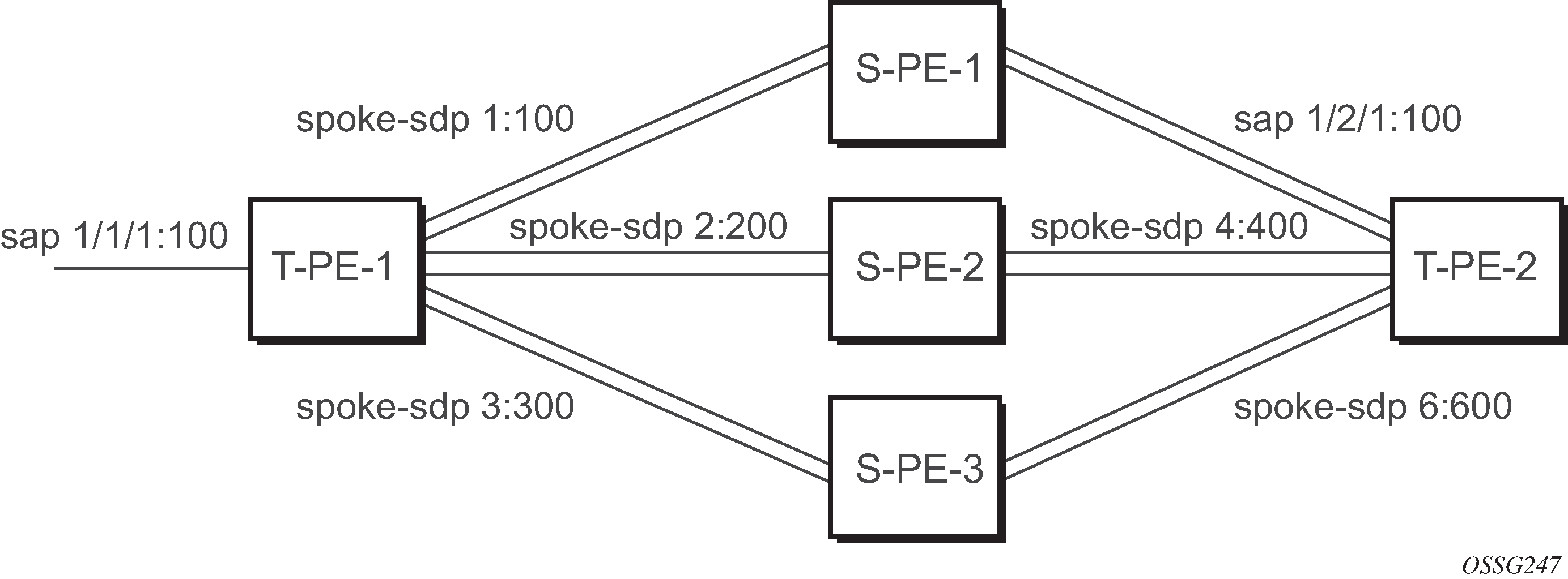
T-PE-1
The following example shows the configuration on T-PE-1.
*A:ALA-48>config>service>epipe# info
----------------------------------------------
            endpoint "x" create
            exit
            endpoint "y" create
            exit
            sap 1/1/1:100 endpoint "x" create
            exit
            spoke-sdp 1:100 endpoint "y" create
                precedence primary
            exit
            spoke-sdp 2:200 endpoint "y" create
                precedence 1
            exit
            spoke-sdp 3:300 endpoint "y" create
                precedence 1
            exit
            no shutdown
----------------------------------------------
*A:ALA-48>config>service>epipe#
T-PE-2
The following example shows the configuration on T-PE-2.
*A:ALA-49>config>service>epipe# info
----------------------------------------------
            endpoint "x" create
            exit
            endpoint "y" create
                revert-time 100
            exit
            spoke-sdp 4:400 endpoint "y" create
                precedence primary
            exit
            spoke-sdp 5:500 endpoint "y" create
                precedence 1
            exit
            spoke-sdp 6:600 endpoint "y" create
                precedence 1
            exit
            no shutdown
----------------------------------------------
*A:ALA-49>config>service>epipe#
S-PE-1
The following example shows the configuration on S-PE-1.
*A:ALA-50>config>service>epipe# info
----------------------------------------------
...
            spoke-sdp 1:100 create
            exit
            spoke-sdp 4:400 create
            exit
            no shutdown
----------------------------------------------
*A:ALA-49>config>service>epipe#
Configuring BGP VPWS
Single-homed BGP VPWS
The following figure shows an example topology for a BGP VPWS service used to create a virtual lease-line across an MPLS network between sites A and B.
An Epipe is configured on PE1 and PE2 with BGP VPWS enabled. PE1 and PE2 are connected to site A and B, respectively, each using a SAP. The interconnection between the two PEs is achieved through a pseudowire, using Ethernet VLAN encapsulation, which is signaled using BGP VPWS over a tunnel LSP between PE1 and PE2. A MIP or MEP can be configured on a BGP VPWS SAP. However, fault propagation between a MEP and the BGP update state signaling is not supported. BGP VPWS routes are accepted only over an IBGP session.
The following example shows the BGP VPWS configuration on each PE.
PE1:
pw-template 1 create
    vc-type vlan
exit
epipe 1 customer 1 create
    bgp
        route-distinguisher 65536:1
        route-target export target:65536:1 import target:65536:1
        pw-template-binding 1
        exit
    exit
    bgp-vpws
        ve-name PE1
            ve-id 1
        exit
        remote-ve-name PE2
            ve-id 2
        exit
        no shutdown
    exit
    sap 1/1/1:1 create
    exit
    no shutdown
exit

PE2:

pw-template 1 create
    vc-type vlan
exit
epipe 1 customer 1 create
    bgp
        route-distinguisher 65536:2
        route-target export target:65536:1 import target:65536:1
        pw-template-binding 1
        exit
    exit
    bgp-vpws
        ve-name PE2
            ve-id 2
        exit
        remote-ve-name PE1
            ve-id 1
        exit
        no shutdown
    exit
    sap 1/1/1:1 create
    exit
    no shutdown
exit
The BGP-VPWS update can be displayed using the following command:
A:PE1# show service l2-route-table bgp-vpws detail
===============================================================================
Services: L2 Bgp-Vpws Route Information - Summary
===============================================================================
Svc Id         : 1
VeId           : 2
PW Temp Id     : 1
RD             : *65536:2
Next Hop       : 10.1.1.2
State (D-Bit)  : up(0)
Path MTU       : 1514
Control Word   : 0
Seq Delivery   : 0
Status         : active
Tx Status      : active
CSV            : 0
Preference     : 0
Sdp Bind Id    : 17407:4294967295
===============================================================================
A:PE1#
Dual-homed BGP VPWS
Single pseudowire example:
The following figure shows an example topology for a dual-homed BGP VPWS service used to create a virtual lease line (VLL) across an MPLS network between sites A and B. A single pseudowire is established between the designated forwarder of the dual-homed PEs and the remote PE.
An Epipe with BGP VPWS enabled is configured on each PE. Site A is dual-homed to PE1 and PE2 with a remote PE (PE3) connected to site B; each connection uses a SAP. A single pseudowire using Ethernet Raw Mode encaps connects PE3 to PE1. The pseudowire is signaled using BGP VPWS over a tunnel LSP between the PEs.
Site A is configured on PE1 and PE2 with the BGP route selection, the site state, and the site-preference used to ensure PE1 is the designated forwarder when the network is fully operational.
The following example shows the BGP VPWS configuration on each PE.
The following example shows the configuration on PE1:
pw-template 1 create
exit
epipe 1 customer 1 create
    bgp
        route-distinguisher 65536:1
        route-target export target:65536:1 import target:65536:1
        pw-template-binding 1
        exit
    exit
    bgp-vpws
        ve-name PE1
            ve-id 1
        exit
        remote-ve-name PE3
            ve-id 3
        exit
        no shutdown
    exit
    sap 1/1/1:1 create
    exit
    site "siteA" create
        site-id 1
        sap 1/1/1:1
        boot-timer 20
        site-activation-timer 5
        no shutdown
    exit
    no shutdown
exit
The following example shows the configuration on PE2:
pw-template 1 create
exit
epipe 1 customer 1 create
    bgp
        route-distinguisher 65536:2
        route-target export target:65536:1 import target:65536:1
        pw-template-binding 1
        exit
    exit
    bgp-vpws
        ve-name PE2
            ve-id 1
        exit
        remote-ve-name PE3
            ve-id 3
        exit
        no shutdown
    exit
    sap 1/1/1:1 create
    exit
    site "siteA" create
        site-id 1
        sap 1/1/1:1
        boot-timer 20
        site-activation-timer 5
        no shutdown
    exit
    no shutdown
exit
The following example shows the configuration on PE3:
pw-template 1 create
exit
epipe 1 customer 1 create
    bgp
        route-distinguisher 65536:3
        route-target export target:65536:1 import target:65536:1
        pw-template-binding 1
        exit
    exit
    bgp-vpws
        ve-name PE3
            ve-id 3
        exit
        remote-ve-name PE1orPE2
            ve-id 1
        exit
        no shutdown
    exit
    sap 1/1/1:1 create
    exit
    no shutdown
exit
Active/standby pseudowire example:
The following figure shows an example topology for a dual-homed BGP VPWS service used to create a VLL across an MPLS network between sites A and B. Two pseudowires are established between the remote PE and the dual-homed PEs. The active pseudowire used for the traffic is the one connecting the remote PE to the designated forwarder of the dual-homed PEs.
An Epipe with BGP VPWS enabled is configured on each PE. Site A is dual-homed to PE1 and PE2 with a remote PE (PE3) connected to site B; each connection uses a SAP. Active/standby pseudowires using Ethernet Raw Mode encapsulation connect PE3 to PE1 and PE2, respectively. The pseudowires are signaled using BGP VPWS over a tunnel LSP between the PEs.
Site A is configured on PE1 and PE2 with the site-preference set to ensure that PE1 is the designated forwarder when the network is fully operational. An endpoint is automatically created on PE3 in which the active/standby pseudowires are created.
The following example shows the BGP VPWS configuration on each PE.
Example: Dual-homed BGP VPWS configuration with active/standby pseudowires on PE1:
pw-template 1 create
exit
epipe 1 customer 1 create
    bgp
        route-distinguisher 65536:1
        route-target export target:65536:1 import target:65536:1
        pw-template-binding 1
        exit
    exit
    bgp-vpws
        ve-name PE1
            ve-id 1
        exit
        remote-ve-name PE3
            ve-id 3
        exit
        no shutdown
    exit
    sap 1/1/1:1 create
    exit
    site "siteA" create
        site-id 1
        sap 1/1/1:1
        boot-timer 20
        site-activation-timer 5
        site-preference 200
        no shutdown
    exit
    no shutdown
exit
Example: Dual-homed BGP VPWS configuration with active/standby pseudowires on PE2:
pw-template 1 create
exit
epipe 1 customer 1 create
    bgp
        route-distinguisher 65536:2
        route-target export target:65536:1 import target:65536:1
        pw-template-binding 1
        exit
    exit
    bgp-vpws
        ve-name PE2
            ve-id 2
        exit
        remote-ve-name PE3
            ve-id 3
        exit
        no shutdown
    exit
    sap 1/1/1:1 create
    exit
    site "siteA" create
        site-id 1
        sap 1/1/1:1
        boot-timer 20
        site-activation-timer 5
        site-preference 10
        no shutdown
    exit
    no shutdown
exit
Example: Dual-homed BGP VPWS configuration with active/standby pseudowires on PE3:
pw-template 1 create
exit
epipe 1 customer 1 create
    bgp
        route-distinguisher 65536:3
        route-target export target:65536:1 import target:65536:1
        pw-template-binding 1
        exit
    exit
    bgp-vpws
        ve-name PE3
            ve-id 3
        exit
        remote-ve-name PE1
            ve-id 1
        exit
        remote-ve-name PE2
            ve-id 2
        exit
        no shutdown
    exit
    sap 1/1/1:1 create
    exit
    no shutdown
exit
Service management tasks
This section discusses VLL service management tasks.
Modifying a Cpipe service
The following example shows the Cpipe service configuration, supported on the 7750 SR only:
*A:ALA-1>config>service# info
----------------------------------------------
...
        cpipe 94002 customer 1 vc-type cesopsn create
            endpoint "to7705" create
            exit
            endpoint "toMC-APS" create
            exit
            sap aps-4.10.1.2.1 endpoint "toMC-APS" create
                ingress
                    qos 20
                exit
            exit
            spoke-sdp 14004:94002 endpoint "to7705" create
            exit
            spoke-sdp 100:294002 endpoint "toMC-APS" icb create
            exit
            spoke-sdp 100:194002 endpoint "to7705" icb create
            exit
            no shutdown
        exit
...
----------------------------------------------
*A:ALA-1>config>service> Cpipe#
Deleting a Cpipe service
A Cpipe service cannot be deleted until SAPs are shut down and deleted. If a spoke-SDP is defined, it must be shut down and removed from the configuration as well.
Use the following CLI syntax to delete a Cpipe service.
CLI syntax:
config>service#
[no] cpipe service-id [customer customer-id]
   [no] spoke-sdp sdp-id
      [no] shutdown
   shutdown
Modifying Epipe service parameters
The following example shows how to add an accounting policy to an existing SAP:
config>service# epipe 2
config>service>epipe# sap 2/1/3:21
config>service>epipe>sap# accounting-policy 14
config>service>epipe>sap# exit
The following example shows the SAP configuration:
ALA-1>config>service# info
----------------------------------------------
    epipe 2 customer 6 vpn 2 create
            description "Distributed Epipe service to east coast"
            sap 2/1/3:21 create
              accounting-policy 14
            exit
            spoke-sdp 2:6000 create
            exit
            no shutdown
        exit
----------------------------------------------
ALA-1>config>service#
Disabling an Epipe service
You can shut down an Epipe service without deleting the service parameters.
CLI syntax:
config>service> epipe service-id
shutdown
Example:
config>service# epipe 2
config>service>epipe# shutdown
config>service>epipe# exit
Re-enabling an Epipe service
Use the following CLI syntax to re-enable an Epipe service that was shut down.
CLI syntax:
config>service# epipe service-id
no shutdown
Example:
config>service# epipe 2
config>service>epipe# no shutdown
config>service>epipe# exit
Deleting an Epipe service
- Shut down the SAP and SDP.
- Delete the SAP and SDP.
- Shut down the service.
-
Use the following CLI syntax to delete an Epipe service:
config>service
      [no] epipe service-id
          shutdown
          [no] sap sap-id
              shutdown
      [no] spoke-sdp sdp-id:vc-id
              shutdown
config>service# epipe 2
config>service>epipe# sap 2/1/3:21
config>service>epipe>sap# shutdown
config>service>epipe>sap# exit
config>service>epipe# no sap 2/1/3:21
config>service>epipe# spoke-sdp 2:6000
config>service>epipe>spoke-sdp# shutdown
config>service>epipe>spoke-sdp# exit
config>service>epipe# no spoke-sdp 2:6000
config>service>epipe# epipe 2
config>service>epipe# shutdown
config>service>epipe# exit
config>service# no epipe 2
Modifying Ipipe service parameters
The following example shows the command usage to modify Ipipe parameters, supported on the 7450 ESS and 7750 SR only.
Example:
config>service# ipipe 202
config>service>ipipe# sap 1/1/2:444
config>service>ipipe>sap# shutdown
config>service>ipipe>sap# exit
config>service>ipipe# no sap 1/1/2:444
config>service>ipipe# sap 1/1/2:555 create
config>service>ipipe>sap$ description ‟eth_ipipe”
config>service>ipipe>sap$ ce-address 10.31.31.1
config>service>ipipe>sap$ no shutdown
config>service>ipipe>sap$ exit
config>service>ipipe# info
A:ALA-48>config>service# info
----------------------------------------------
...
        ipipe 202 customer 1 create
            sap 1/1/2:445 create
                description "eth_ipipe"
                ce-address 10.31.31.2
            exit
            sap 1/1/2:555 create
                description "eth_ipipe"
                ce-address 10.31.31.1
            exit
            no shutdown
        exit
...
----------------------------------------------
A:ALA-48>config>service#
Disabling an Ipipe service
An Ipipe service can be shut down without deleting any service parameters.
CLI syntax:
config>service#
ipipe service-id
  shutdown
Example:
A:ALA-41>config>service# ipipe 202
A:ALA-41>config>service>ipipe# shutdown
A:ALA-48>config>service# info
----------------------------------------------
...
       ipipe 202 customer 1 create
           shutdown
           sap 1/1/2:445 create
               description "eth_ipipe"
               ce-address 10.31.31.2
           exit
           sap 1/1/2:555 create
               description "eth_ipipe"
               ce-address 10.31.31.1
           exit
       exit
...
----------------------------------------------
A:ALA-48>config>service#
Re-enabling an Ipipe service
Use the following CLI syntax to re-enable an Ipipe service that was shut down.
CLI syntax:
config>service#
ipipe service-id
   no shutdown
Example:
A:ALA-41>config>service# ipipe 202
A:ALA-41>config>service>ipipe# no shutdown
Deleting an Ipipe service
An Ipipe service cannot be deleted until the SAP is shut down. If protocols and, or a spoke-SDP are defined, they must be shut down and removed from the configuration as well.
Use the following CLI syntax to delete an Ipipe service.
CLI syntax:
config>service#
    — no ipipe service-id
        — shutdown
        — no sap sap-id
            — shutdown
        — no spoke-sdp [sdp-id:vc-id]
            — shutdown
Example:
config>service# ipipe 207
config>service>ipipe# sap 1/1/2:449
config>service>ipipe>sap# shutdown
config>service>ipipe>sap# exit
config>service>ipipe# no sap 1/1/2:449
config>service>ipipe# spoke-sdp 16:516
config>service>ipipe>spoke-sdp# shutdown
config>service>ipipe>spoke-sdp# exit
config>service>ipipe# no spoke-sdp 16:516
config>service>ipipe# exit
config>service# no ipipe 207
config>service#