MLDP
Dynamic multicast signaling over P2MP in GRT instance
This feature provides a flexible multicast signaling solution to connect native IP multicast source and receivers running PIM multicast protocol via an intermediate MPLS (P2MP LDP LSP) network. The feature allows each native IP multicast flow to be connected via an intermediate P2MP LSP by dynamically mapping each PIM multicast flow to a P2MP LDP LSP.
The feature uses procedures defined in RFC 6826: Multipoint LDP In-Band Signaling for Point-to-Multipoint and Multipoint-to-Multipoint Label Switched Paths. On the leaf node of a P2MP LSP, PIM signaling is dynamically mapped to P2MP LDP tree setup. On the root node of P2MP LSP, P2MP LDP signaling is handed back to PIM. Because of dynamic mapping of multicast IP flow to P2MP LSP, provisioning and maintenance overhead is eliminated as multicast distribution services are added and removed from the network. Per (S,G) IP multicast state is also removed from the network where P2MP LSPs are used to transport multicast flows.
Dynamic MLDP signaling for IP multicast in GRT illustrates dynamic MLDP signaling for IP multicast in GRT.
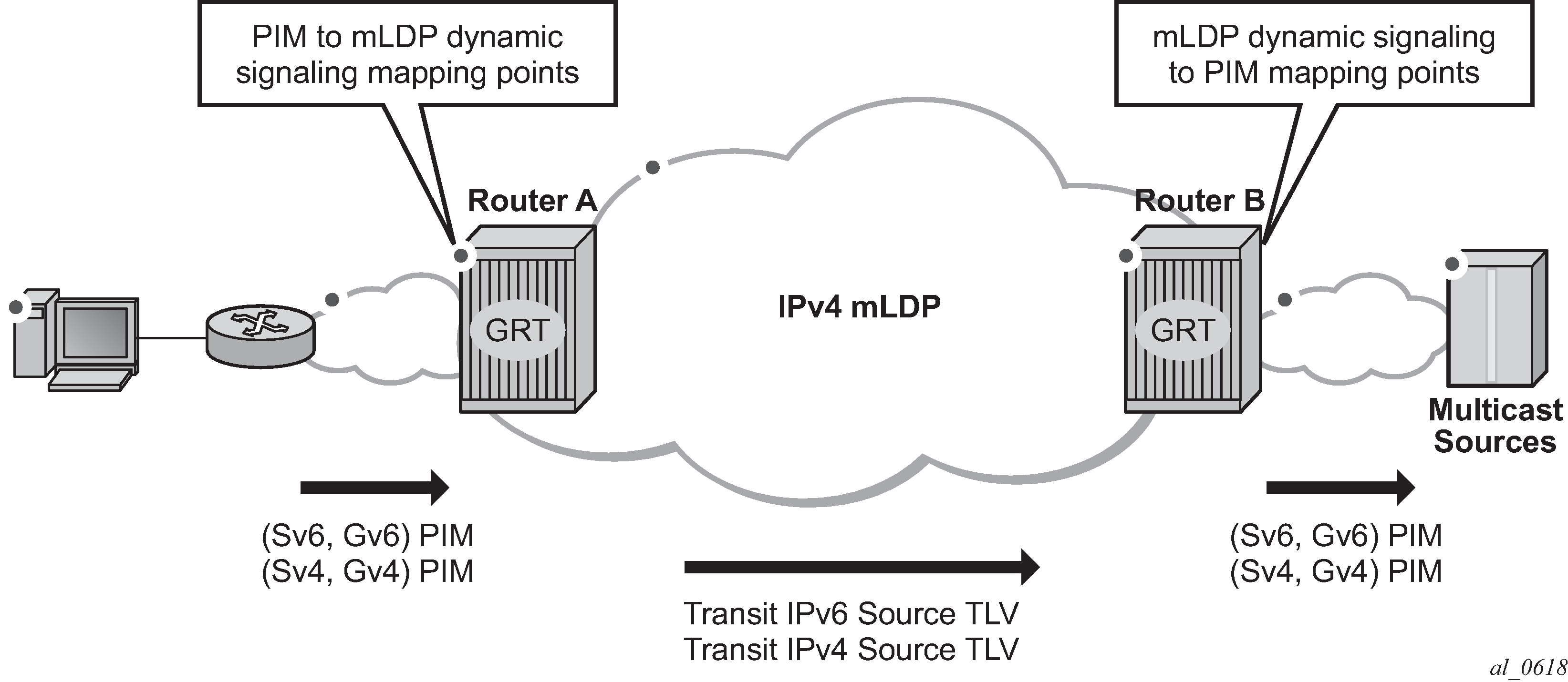
As illustrated in Dynamic MLDP signaling for IP multicast in GRT, P2MP LDP LSP signaling is initiated from the router that receives PIM JOIN from a downstream router (Router A). To enable dynamic multicast signaling, p2mp-ldp-tree-join must be configured on PIM outgoing interface of Router A. This enables handover of multicast tree signaling from PIM to P2MP LDP LSP. Being a leaf node of P2MP LDP LSP, Router A selects the upstream-hop as the root node of P2MP LDP FEC based on routing table lookup. If an ECMP path is available for a specific route, then the number of trees are equally balanced toward multiple root nodes. The PIM Joins are carried in Transit IPv4 (IPv4 PIM-SSM) or IPv6 (IPv6 PIM-SSM) MLDP TLVs. On the root node of P2MP LDP LSP (Router B), multicast tree signaling is handed back to PIM and propagated upstream as native-IP PIM JOIN.
The feature is supported with IPv4 and IPv6 PIM-SSM and IPv4 MLDP. Directly connected IGMP/MLD receivers are also supported with PIM enabled on outgoing interfaces and SSM mapping configured if required.
If multiple criteria exist to setup a multicast flow, the priority is given as follows:
Multicast (statically provisioned) over P2MP LSP (RSVP-TE or LDP)
Dynamic multicast signaling over P2MP LDP
PIM native-IP multicast
The following are feature restrictions:
A single instance of P2MP LDP LSP is supported between the root and leaf nodes per multicast flow; there is no stitching of dynamic trees.
Extranet functionality is not supported.
The router LSA link ID or the advertising router ID must be a routable IPv4 address (including IPv6 into IPv4 MLDP use cases).
IPv6 PIM with dynamic IPv4 MLDP signaling is not supported with e-BGP or i-BGP with IPv6 next-hop.
Inter-AS and IGP inter-area scenarios where the originating router is altered at the ASBR and ABR respectively, (therefore PIM has no way to create the LDP LSP toward the source), are not supported.
Inter-AS non-segmented MLDP
This feature allows multicast services to use segmented protocols and span them over multiple autonomous systems (ASs), as done in unicast services. As IP VPN or GRT services span multiple IGP areas or multiple ASs, either for a network designed to deal with scale or as result of commercial acquisitions, operators may require Inter-AS VPN (unicast) connectivity. For example, an Inter-AS VPN can break the IGP, MPLS and BGP protocols into access segments and core segments, allowing higher scaling of protocols by segmenting them into their own islands. SR OS also allows for similar provision of multicast services and for spanning these services over multiple IGP areas or multiple ASs.
For multicast VPN (MVPN), SR OS previously supported Inter-AS option A/B/C for Rosen MVPN; however, when MPLS was used, only option A was supported for Next Generation Multicast VPN (NG-MVPN) or d-MLDP signaling. MLDP now supports non-segmented MLDP trees for inter-AS solutions, applicable for multicast services in the GRT (Global Routing Table) where they need to ride over MLDP point-to-multipoint tunnels as well as NG-MVPN services.
See the ‟ECMP Support” subsection of the ‟Inter-AS Non-segmented MLDP” section in the 7450 ESS, 7750 SR, 7950 XRS, and VSR MPLS Guide for more information.
See the ‟Dynamic mLDP and Static mLDP Co-existing on Same Node” section in the 7450 ESS, 7750 SR, 7950 XRS, and VSR MPLS Guide for more information.
d-MLDP inter-AS trees in GRT
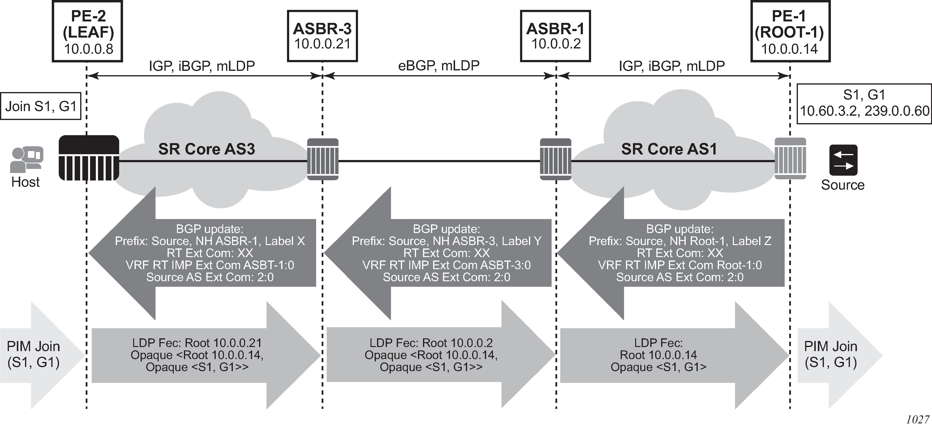
In-band signaling with non-segmented inter-AS MLDP trees in GRT shows the processing required for d-mLDP with non-segmented mLDP Inter-AS trees in GRT (routers in AS3, including ASBR 1, have no route to ROOT-1 in IGP and must use BGP unicast routes to resolve route to ROOT-1 and to multicast source).
PE-1 (ROOT-1) is the root node of the MLDP tree, and PE-2 (LEAF) is the leaf node.
Routing
BGP unicast routes must advertise to the VRF Route Import Ext Community, identifying the root PE, for the feature to operate properly. Failure to do so results in PIM Inter-AS joins being dropped.
The community is an address-based community where the global administrator field is the address of the root PE and local administrator field is set to 0 (GRT). No new configuration is required; however, an operator must enable inter-AS VPN and configure export policy to ensure the community is added to the BGP routes as required. The BGP unicast route is propagated across the AS, as shown in In-band signaling with non-segmented inter-AS MLDP trees in GRT (the same processing, not shown, applies to a BGP route specifying address used to build mLDP tree rooted at ROOT-1). The following configuration example shows an export policy configuration.
policy-options
        — begin
        — community "A" members "target:1.1.1.1:0"
        — community "B" members "ext:010b:0a1401060000"
            — policy-statement "fromlocal"
                — entry 10
                    — from
                        — protocol direct
                    — exit
                    — to
                        — protocol bgp
                    — exit
                    — action accept
                        — community add "A" "B"
                    — exit
                — exit
                — default-action reject
        — exit
        — policy-statement "accept_all"
            — default-action accept
            — exit
        — exit
        — commit
    exit
    bgp
    …
        — enable-inter-as-vpn
        — …
        — export "fromlocal" "accept_all"
        — …
        —  no shutdown
    exit
Static routes must be configured on inter-ASBR LDP-enabled links because the BGP peer uses a host address from the local subnet of the links (for GRT and VPN option C), or the BGP peer uses a system IP address that is not in the base routing table (for VPN option B).
For system-IP to system-IP, static-routes are required for bringing up the EBGP/LDP session.
If the link IP is used for creation of EBGP and ILD, then static-routes are not required; however, static-route (host-route) is mandatory on ASBR2 for the resolution of MLDP FEC, as the link LSR ID is not resolved by LDP using a /24 route; it needs a /32 route.
Join processing
To traverse an inter-AS domain, recursive FECs are required (see the ‟Inter-AS Non-segmented MLDP” section in the 7450 ESS, 7750 SR, 7950 XRS, and VSR MPLS Guide for more information).
The operator must enable dynamic signaling on interfaces where Inter-AS joins are expected to be received using the existing configuration (p2mp-ldp-tree-join [ipv4] [ipv6]). When enabled, the following describes the required processing of a PIM join, as shown in In-band signaling with non-segmented inter-AS MLDP trees in GRT .
When the leaf receives a PIM join for group (S1, G1) and, through configuration, knows dynamic signaling is required, the leaf fails to resolve the source S1 via IGP and attempts to resolve route via BGP. The leaf learns that source is reachable via Next-Hop ASBR3 and the route was advertised by PE1 (Root-1) (from VRF Import Ext Community). PE2 (leaf) sources a Recursive mLDP FEC with a root node of ASBR3, and an opaque value containing the MLDP in-band signaling information identifying the (S1, G1) group and the Root-1 (the root of the inter-AS non-segmented MLDP tree), as shown below:
LEAF FEC {Root = ASBR3, Opaque Value = {Root: ROOT-1, Opaque Value (S1, G1)}}—The FEC is forwarded using IGP to ASBR3.
When the Recursive MLDP FEC arrives at ASBR3, it notes that it is the identified root node in the local AS, and that the opaque value is a Recursive Opaque Value. Because ASBR3 fails to resolve the Recursive FEC’s root (Root-1) in IGP, ASBR3 attempts to resolves the root via BGP. Similarly to processing on LEAF, this yields a Next-Hop of ASBR1. ASBR3 creates a new mLDP FEC element with a root node of ASBR1, and the Opaque value as per received opaque value, as shown below:
ASBR3 FEC {Root = ASBR1, Opaque Value = {Root: Root-1, Opaque Value (S1, G1)}}—ASBR 3 forwards the FEC using IGP or EBGP.
When the MLDP FEC arrives at ASBR1, it notes that it is the identified root node, and that the opaque value is a Recursive Opaque value. Because ASBR1 can resolve the Recursive FEC’s root (Root-1) via IGP, no further recursive processing is required. ASBR 1 forwards mLDP FEC containing in-band signaling using IGP toward ROOT-1.
ASBR support of PE functionality
Remote and local ASBRs displays remote and local ASBRs.

While ASBRs can also act as PE nodes, SR OS does not support all PE functionalities in the ASBR node. PE features on ASBRs lists supported PE features on ASBRs.
| ASBR node | ||
|---|---|---|
| Inter-AS multicast context | Leaf or bud | Root or source |
GRT |
✓ |
|
VPN |
✓ |
✓ |
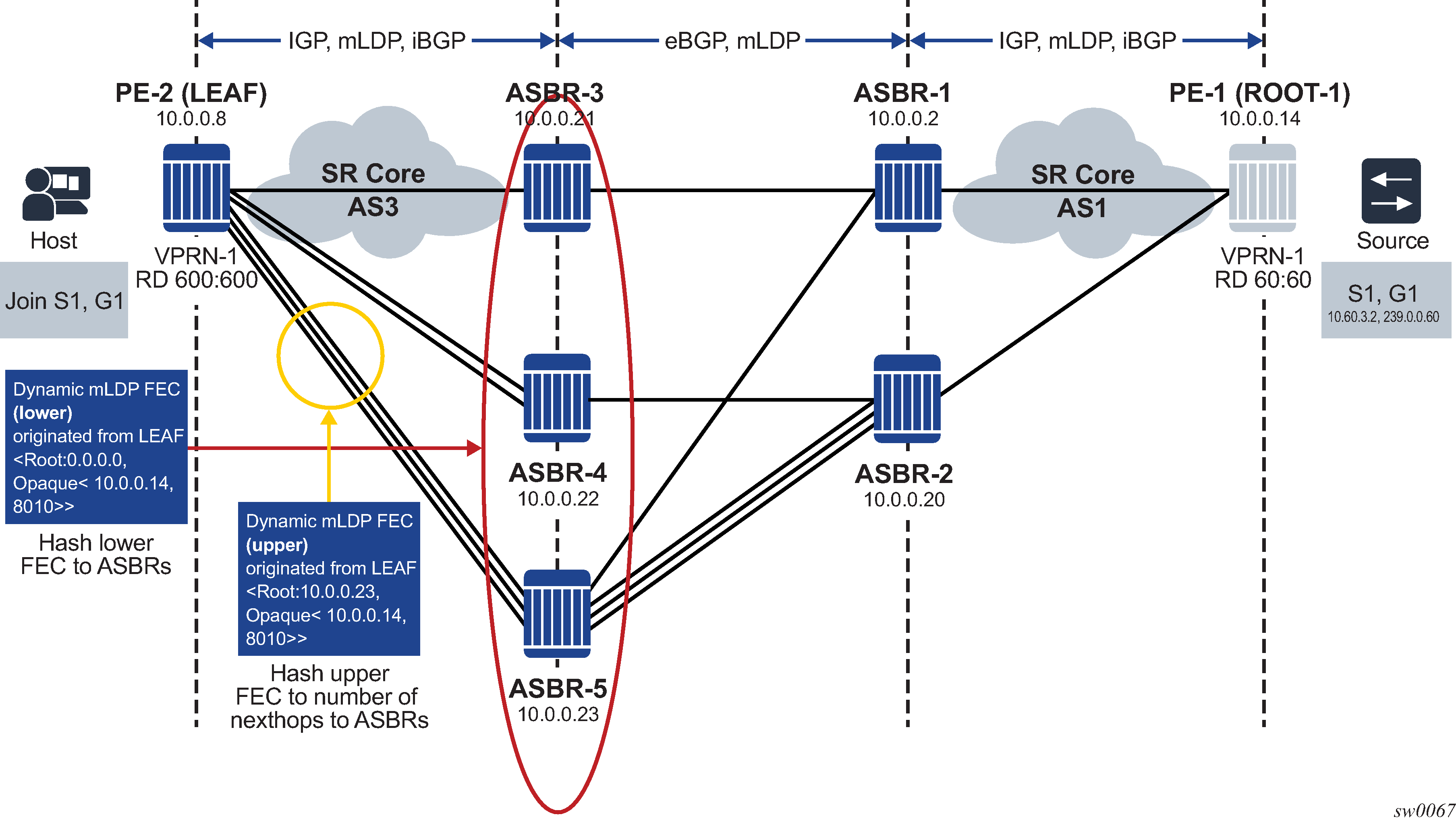
Hashing for inter-AS
At each leaf or ASBR, there are two FECs: a lower FEC and an upper FEC. The lower FEC is used for hashing to multiple ASBRs and the upper FEC is used to choose the next-hop that connects the leaf node to the ASBR. Hashing is performed based on the opaque value of the FEC. See the ‟Supported Recursive Opaque Values” section in the 7450 ESS, 7750 SR, 7950 XRS, and VSR MPLS Guide for more information.
In Hashing for inter-AS, the leaf generates a lower FEC <0.0.0.0, opaque <10.0.0.14, 8010>>. The lower FEC’s opaque <10.0.0.14, 8010> and number of ASBRs (three) are used to decide which ASBR is used based on hashing. After hashing produces ASBR-5 as the result, the upper FEC of <10.0.0.23, opaque <10.0.0.14, 8010>> is created. This upper FEC is used to resolve the ASBR-5 next-hop between the three interfaces that connect the leaf node to ASBR-5.
Hashing at the ASBR
Hashing at the ASBR illustrates hashing at the ASBR.

In Hashing at the ASBR, the leaf node has ROOT-1 in the RTM for optimized Option C; therefore, the leaf does not generate a recursive type 7 opaque, and only generates a type 1 opaque. When the FEC arrives at ASBR-3, it has a basic type 1 FEC of <ROOT: 10.0.0.14, opaque <8010>>.
If the ASBR also has a host that generates a mLDP LSP toward the root, this FEC looks up <ROOT: 0.0.0.0, opaque <10.0.0.14, 8010>>.
Hashing is performed based on the opaque value of the FEC. See ‟Supported Recursive Opaque Values” in the 7450 ESS, 7750 SR, 7950 XRS, and VSR MPLS Guide for more information.
The opaque of the leaf node is not the same as the opaque of the ASBR bud node. In this scenario, the two LSPs generate a different ASBR as the next-hop, inefficiently duplicating multicast traffic.
To prevent this problem, SR OS converts the lower FEC of opaque type 1 that arrives from the leaf node into a recursive type 7 FEC, so that the bud FEC generated by the ASBR and the FEC arriving from the leaf node results in the same upper ASBR.
MLDP over RSVP P2P LSP
The following use cases are described in this section:
tunneling MLDP over P2P RSVP on core nodes that do not have multicast protocols enabled and are protected through RSVP FRR and TE
protecting MLDP P2MP over RSVP P2P on a network-segment basis; in networks that cannot afford duplication of multicast bandwidth (MoFRR), it is attractive to use MLDP over RSVP and reserve RSVP FRR for link and node protection.
Summary of procedures for MLDP over RSVP
The following CLI options under the existing ldp command advertise an MLDP P2MP FEC to an upstream node using a T-LDP session. See the Classic CLI Command Reference Guide for command details.
configure router ldp prefer-mcast-tunnel-in-tunnel
configure router ldp targeted-session peer mcast-tunneling
The following apply when LDP mcast-tunneling is enabled on the ELER (downstream) and prefer-mcast-tunnel-in-tunnel and LDP mcast-tunneling are enabled on ILER (upstream):
On the upstream router, LDP resolves the nexthop using TTM using a P2P RSVP-TE LSP.
As shown in Configuring MLDP over RSVP P2P LSP, when the LSR 100.0.0.102 and LSR 100.0.0.101 nodes are directly connected, the T-LDP and link-LDP adjacencies share a common LDP session. The P2MP FEC is advertised over the LDP session and is received by LSR 100.0.0.102, which resolves it over the RSVP LSP if the mcast-tunneling option is enabled. The prefer-mcast-tunnel-in-tunnel option in LDP dictates if the MLDP FEC is resolved in preference to the tunnel or to the link.
Figure 6. Configuring MLDP over RSVP P2P LSP 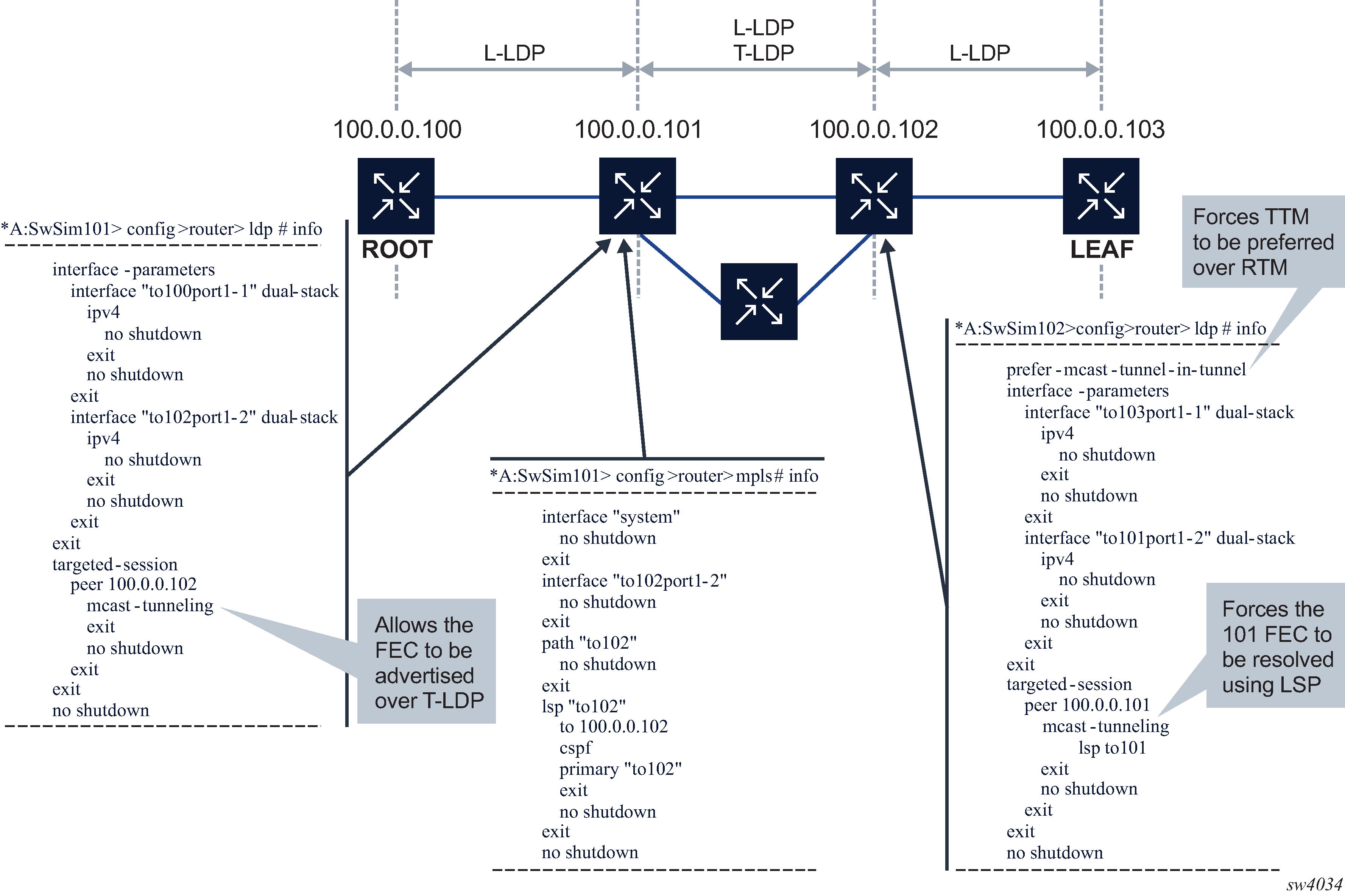
Summary of requirements and procedures for IGP shortcut
The main difference between IGP shortcut and LDP over RSVP-TE is that the LSP is installed in the RIB with IGP shortcut. The T-LDP signaling messages are resolved through IGP shortcut and go over the P2P RSVP-TE. In the case of LDP over RSVP-TE, the P2P RSVP-TE is not installed in the RIB, so the T-LDP signaling is not over RSVP.
The tunneling command is required to ensure the label mapping is generated through T-LDP.
For upstream FEC resolution:
mcast-tunneling must be enabled under the targeted peer for the mcast FEC to resolve over an IGP shortcut or using T-LDP.
If prefer-mcast-tunnel-in-tunnel is disabled, the preference is given in the following order:
non-tunneled NHs of IGP route
IGP shortcut (tunneled NHs) of IGP route
direct T-LDP to the root address
indirect T-LDP to an intermediate node using the tunnel endpoints provided by routing; for IGP to compute the tunnel endpoints, the ldp-over-rsvp command must be enabled under the IGP context
If prefer-mcast-tunnel-in-tunnel is enabled, the preference is given in the following order:
direct T-LDP to root address
indirect T-LDP to an intermediate node using the tunnel endpoints
IGP shortcut (tunneled NHs) of IGP route
non-tunneled NHs of IGP route
For the downstream direction, a direct RSVP LSP to the downstream peer address is required for T-LDP sessions to be considered.
When the downstream peer is reachable through both a link LDP and a T-LDP, the mcast FEC next-hop is programmed as follows:
The link LDP session is preferred if prefer-mcast-tunnel-in-tunnel is disabled.
The T-LDP session is preferred if prefer-mcast-tunnel-in-tunnel is enabled.
FEC T-LDP session selection
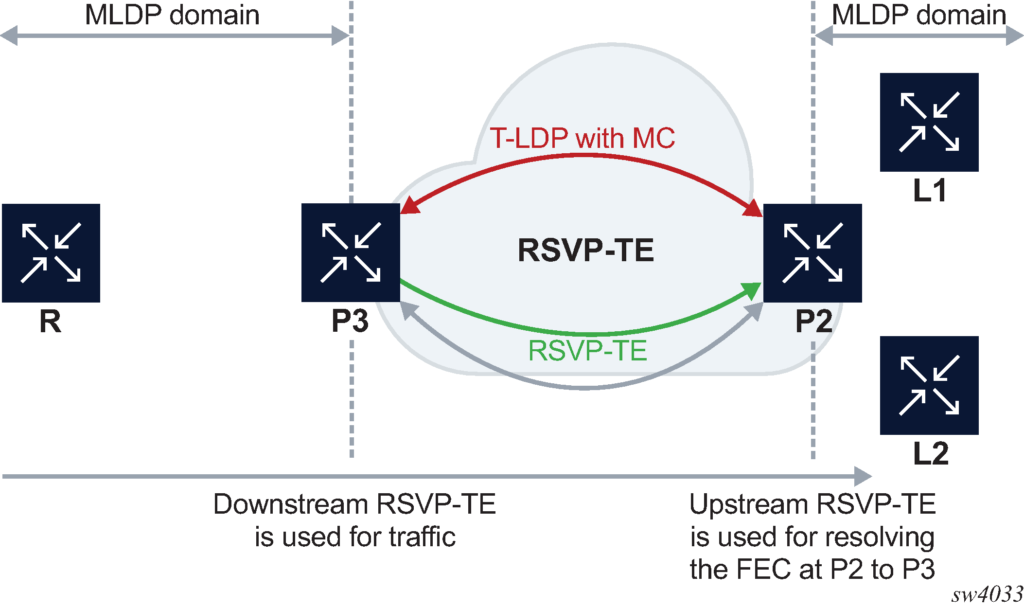
FEC T-LDP session selection shows an example of the FEC T-LDP session selection process.
T-LDP is used to signal MLDP over a core of RSVP-TE. The criteria for selecting the T-LDP session is as follows:
A T-LDP session with multicast enabled is selected.
An RSVP-TE LSP may be needed to terminate at the upstream node. The RSVP-TE far-end must be equal to the T-LDP peer. The FEC selects a T-LDP session that has an upstream direction RSVP-TE.
Basic FEC and recursive FEC
MLDP over RSVP P2P LSP supports both basic and recursive FEC.
The outer root address of the recursive FEC is used for the upstream FEC resolution. On ABRs or ASBRs, a new outer root address is generated and used for upstream FEC resolution.
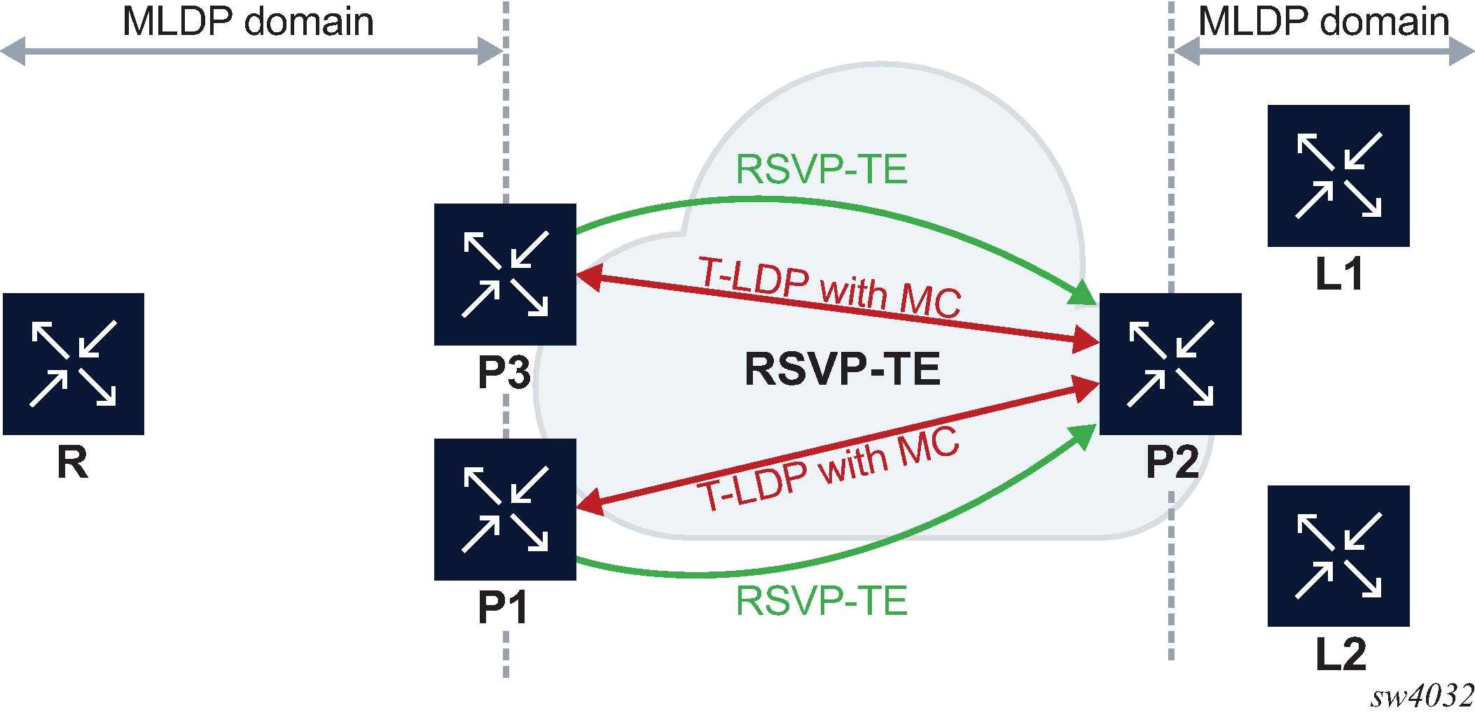
Two nodes with ECMP upstream
In Two nodes with ECMP upstream, the FECs are hashed between P3 and P1. The hashing criteria are in accordance with RFC 6388 section 2.4.1.1. If P3 has a failure, the FEC is signaled through P1 and all tunnels go down and signal again.
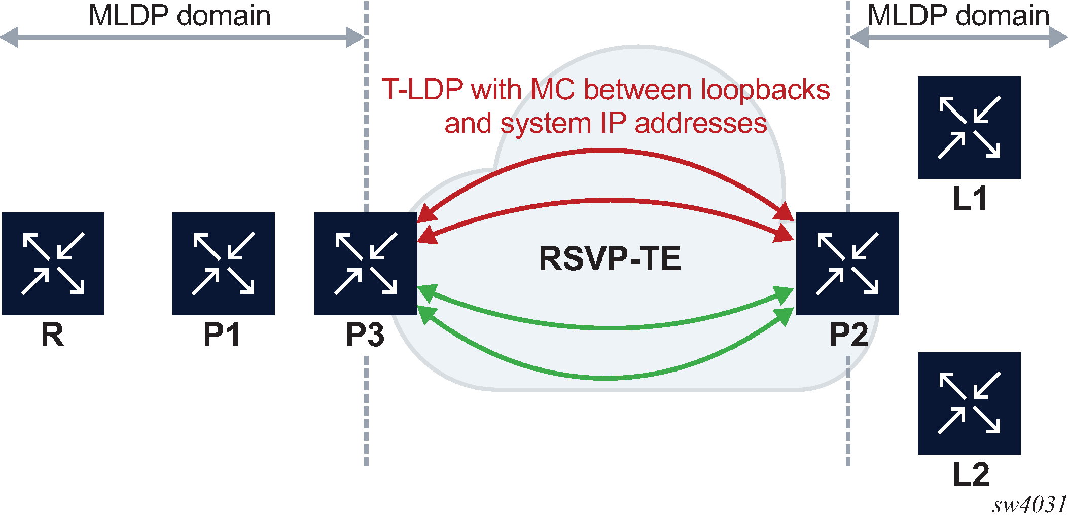
Single upstream node with multiple T-LDP to the upstream node
Single upstream node with multiple T-LDP to the upstream node shows an example of multiple T-LDP sessions to the upstream node.
The T-LDP peer IP that resolves the root is preferred first. Otherwise, the T-LDP peer with the smallest peer address is preferred. There is no ECMP between multiple T-LDP sessions to the same node.
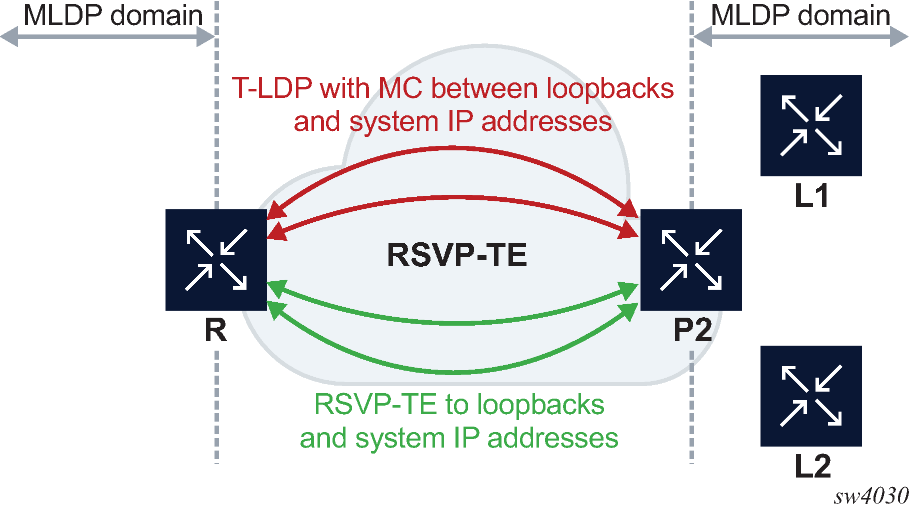
Root node with multiple T-LDP to the root node
Root node with multiple T-LDP to the root node shows an example of multiple T-LDP sessions to the root node.
If the FEC is to the system IP address, the T-LDP peer to the system IP is preferred. Otherwise, the behavior is as described in Single upstream node with multiple T-LDP to the upstream node.
Root and leaf connectivity
The root can be colocated on the egress RSVP-TE router (egress from the signaling point of view). The root can be one hop or more away for the egress RSVP-TE router.
The leaf can be colocated on the ingress RSVP-TE router (ingress from the signaling point of view). The leaf can be one hop or more away downstream from the ingress RSVP-TE router.
IGP shortcut and ldp-over-rsvp knob
In the following example, a bidirectional LSPs is configured between Dut-A and Dut-C.
Dut- A ----------------- Dut-B ------------------ Dut-C
(leaf) (bud) (root)
The IGP shortcut behavior is as follows:
In the upstream direction, if ldp-over-rsvp on the LSP is disabled from Dut-A to Dut-C (ldp-over-rsvp exclude), the FEC is signaled upwards using the LSP. This is because it is a shortcut-based LSP and the ldp-over-rsvp disable configuration has no effect on it.
In the downstream direction, if ldp-over-rsvp on the LSP is disabled from Dut-C to Dut-A, the bindings are removed on Dut-C even if the tunnel is a shortcut tunnel.
T-LDP peer and RSVP-TE far-end
In the upstream direction, the T-LDP peer and the RSVP endpoint can be different.
In the following example, Router A has Router ID 10.20.1.1 and loopback address 1.1.1.1. Router C has Router ID 10.20.1.3 and loopback address 3.3.3.3.
A--------------------------- C
10.20.1.1 10.20.1.3
1.1.1.1 3.3.3.3
In the upstream direction, SR OS can configure the T-LDP peer between 1.1.1.1 and 3.3.3.3 and also configure the RSVP LSP between Router IDs 10.20.1.1 and 10.20.1.3.
In the downstream direction, the RSVP LSP must terminate on the targeted peer for the FEC to get resolved.
MoFRR considerations
MoFRR over RSVP-TE unicast domain is possible if there are multiple RSVP-TE tunnels.
For the direct case, that is, where there is a direct T-LDP session from the leaf node to the root node, LDP MoFRR is not set up. The operator must set up RSVP FRR if redundancy is required.
For the indirect case, that is, where there are T-LDP sessions from the leaf node to the intermediate nodes, LDP sets up MoFRR if multiple eligible tunnel endpoints are provided by IGP and T-LDP sessions exist to these.
LDP uses the tunneled NH tunnel far-end provided in the RTM route to select a phop. If multiple tunneled NH tunnel far-ends are provided, LDP can use one as primary and one as backup to select the phops. If the RTM route has non-tunneled next-hops to multiple phop nodes, it selects a primary and a backup.
For MLDP over RSVP or MLDP over IGP shortcut, upstream MoFRR works only if ECMP is set to 2 or greater. There is currently no support for MoFRR leveraging an LFA route. Without ECMP set to 2 or greater, LDP cannot calculate the backup MoFRR path required for upstream traffic protection. The primary and backup ECMP selected path must be disjoint throughout the RSVP-TE cloud to protect against physical failures.