PIM
PIM overview
PIM-SM leverages the unicast routing protocols that are used to create the unicast routing table, OSPF, IS-IS, BGP, and static routes. Because PIM uses this unicast routing information to perform the multicast forwarding function it is effectively IP protocol independent. Unlike DVMRP, PIM does not send multicast routing tables updates to its neighbors.
PIM-SM uses the unicast routing table to perform the Reverse Path Forwarding (RPF) check function instead of building up a completely independent multicast routing table.
PIM-SM only forwards data to network segments with active receivers that have explicitly requested the multicast group. PIM-SM in the ASM model initially uses a shared tree to distribute information about active sources. Depending on the configuration options, the traffic can remain on the shared tree or switch over to an optimized source distribution tree. As multicast traffic starts to flow down the shared tree, routers along the path determine if there is a better path to the source. If a more direct path exists, then the router closest to the receiver sends a join message toward the source and then reroutes the traffic along this path.
As stated above, PIM-SM relies on an underlying topology-gathering protocol to populate a routing table with routes. This routing table is called the Multicast Routing Information Base (MRIB). The routes in this table can be taken directly from the unicast routing table, or it can be different and provided by a separate routing protocol such as MBGP. Regardless of how it is created, the primary role of the MRIB in the PIM-SM protocol is to provide the next hop router along a multicast-capable path to each destination subnet. The MRIB is used to determine the next hop neighbor to whom any PIM join/prune message is sent. Data flows along the reverse path of the join messages. Thus, in contrast to the unicast RIB that specifies the next hop that a data packet would take to get to some subnet, the MRIB gives reverse-path information, and indicates the path that a multicast data packet would take from its origin subnet to the router that has the MRIB.
PIM-SM functions
PIM-SM functions in three phases:
Phase one
In this phase, a multicast receiver expresses its interest in receiving traffic destined for a multicast group. Typically, the receiver does this using IGMP or MLD, but other mechanisms may also serve this purpose. One of the receiver’s local routers is elected as the DR for that subnet. When the expression of interest is received, the DR sends a PIM join message toward the RP for that multicast group. This join message is known as a (*,G) join because it joins group G for all sources to that group. The (*,G) join travels hop-by-hop toward the RP for the group, and in each router it passes through, the multicast tree state for group G is instantiated. Eventually the (*,G) join either reaches the RP or reaches a router that already has (*,G) join state for that group. When many receivers join the group, their join messages converge on the RP and form a distribution tree for group G that is rooted at the RP. This is known as the RP tree and is also known as the shared tree because it is shared by all sources sending to that group. Join messages are resent periodically, as long as the receiver remains in the group. When all receivers on a leaf-network leave the group, the DR sends a PIM (*,G) prune message toward the RP for that multicast group. However, if the prune message is not sent for any reason, the state eventually times out.
A multicast data sender starts sending data destined for a multicast group. The sender’s local router (the DR) takes those data packets, unicast-encapsulates them, and sends them directly to the RP. The RP receives these encapsulated data packets, removes the encapsulation, and forwards them onto the shared tree. The packets then follow the (*,G) multicast tree state in the routers on the RP tree, being replicated wherever the RP tree branches, and eventually reaching all the receivers for that multicast group. The process of encapsulating data packets to the RP is called registering, and the encapsulation packets are known as PIM register packets.
At the end of phase one, multicast traffic is flowing encapsulated to the RP, and then natively over the RP tree to the multicast receivers.
Phase two
In this phase, register-encapsulation of data packets is performed. However, register-encapsulation of data packets is unsuitable for the following reasons:
Encapsulation and de-encapsulation can be resource intensive operations for a router to perform depending on whether the router has appropriate hardware for the tasks.
Traveling to the RP and then back down the shared tree can cause the packets to travel a relatively long distance to reach receivers that are close to the sender. For some applications, increased latency is unwanted.
Although register-encapsulation can continue indefinitely, for these reasons, the RP normally switches to native forwarding. To do this, when the RP receives a register-encapsulated data packet from source S on group G, it normally initiates an (S,G) source-specific join toward S. This join message travels hop-by-hop toward S, instantiating (S,G) multicast tree state in the routers along the path. (S,G) Multicast tree state is used only to forward packets for group G if those packets come from source S. Eventually the join message reaches S’s subnet or a router that already has (S,G) multicast tree state, and then packets from S start to flow following the (S,G) tree state toward the RP. These data packets can also reach routers with (*,G) state along the path toward the RP - if so, they can short-cut onto the RP tree at this point.
While the RP is in the process of joining the source-specific tree for S, the data packets continue being encapsulated to the RP. When packets from S also start to arrive natively at the RP, the RP receives two copies of each of these packets. At this point, the RP starts to discard the encapsulated copy of these packets and it sends a register-stop message back to S’s DR to prevent the DR unnecessarily encapsulating the packets. At the end of phase two, traffic is flowing natively from S along a source-specific tree to the RP and from there along the shared tree to the receivers. Where the two trees intersect, traffic can transfer from the shared RP tree to the shorter source tree.
Phase three
In this phase, the RP joins back toward the source using the shortest path tree. Although having the RP join back toward the source removes the encapsulation overhead, it does not completely optimize the forwarding paths. For many receivers the route via the RP can involve a significant detour when compared with the shortest path from the source to the receiver.
To obtain lower latencies, a router on the receiver’s LAN, typically the DR, may optionally initiate a transfer from the shared tree to a source-specific shortest-path tree (SPT). To do this, it issues an (S,G) Join toward S. This instantiates state in the routers along the path to S. Eventually this join either reaches S’s subnet or reaches a router that already has (S,G) state. When this happens, data packets from S start to flow following the (S,G) state until they reach the receiver.
At this point the receiver (or a router upstream of the receiver) receives two copies of the data - one from the SPT and one from the RPT. When the first traffic starts to arrive from the SPT, the DR or upstream router starts to drop the packets for G from S that arrive via the RP tree. In addition, it sends an (S,G) prune message toward the RP. The prune message travels hop-by-hop instantiating state along the path toward the RP indicating that traffic from S for G should not be forwarded in this direction. The prune message is propagated until it reaches the RP or a router that still needs the traffic from S for other receivers.
By now, the receiver receives traffic from S along the shortest-path tree between the receiver and S. In addition, the RP is receiving the traffic from S, but this traffic is no longer reaching the receiver along the RP tree. As far as the receiver is concerned, this is the final distribution tree.
Encapsulating data packets in the register tunnel
Conceptually, the register tunnel is an interface with a smaller MTU than the underlying IP interface toward the RP. IP fragmentation on packets forwarded on the register tunnel is performed based upon this smaller MTU. The encapsulating DR can perform path-MTU discovery to the RP to determine the effective MTU of the tunnel. This smaller MTU takes both the outer IP header and the PIM register header overhead into consideration.
PIM bootstrap router mechanism
For correct operation, every PIM-SM router within a PIM domain must be able to map a particular global-scope multicast group address to the same RP. If this is not possible, then black holes can appear (this is where some receivers in the domain cannot receive some groups). A domain in this context is a contiguous set of routers that all implement PIM and are configured to operate within a common boundary.
The bootstrap router (BSR) mechanism provides a way in which viable group-to-RP mappings can be created and distributed to all the PIM-SM routers in a domain. Each candidate BSR originates bootstrap messages (BSMs). Every BSM contains a BSR priority field. Routers within the domain flood the BSMs throughout the domain. A candidate BSR that hears about a higher-priority candidate BSR suppresses its sending of further BSMs for a period of time. The single remaining candidate BSR becomes the elected BSR and its BSMs inform the other routers in the domain that it is the elected BSR.
It is adaptive, meaning that if an RP becomes unreachable, it is detected and the mapping tables are modified so the unreachable RP is no longer used and the new tables are rapidly distributed throughout the domain.
PIM-SM routing policies
Multicast traffic can be restricted from specific source addresses by creating routing policies. Join messages can be filtered using import filters. PIM join policies can be used to reduce denial of service attacks and subsequent PIM state explosion in the router and to remove unwanted multicast streams at the edge of the network before it is carried across the core. Route policies are created in the config>router>policy-options context. Join and register route policy match criteria for PIM-SM can specify the following:
router interface or interfaces specified by name or IP address
neighbor address (the source address in the IP header of the join and prune message)
multicast group address embedded in the join and prune message
multicast source address embedded in the join and prune message
Join policies can be used to filter PIM join messages so no (*,G) or (S,G) state is created on the router.
Join filter policy match conditions lists the join filter policy match conditions.
| Match condition | Matches the: |
|---|---|
Interface |
RTR interface by name |
Neighbor |
The neighbors source address in the IP header |
Group Address |
Multicast Group address in the join/prune message |
Source Address |
Source address in the join/prune message |
PIM register message are sent by the first hop designated router that has a direct connection to the source. This serves a dual purpose:
notifies the RP that a source has active data for the group
delivers the multicast stream in register encapsulation to the RP and its potential receivers
if no one has joined the group at the RP, the RP ignores the registers
In an environment where the sources to particular multicast groups are always known, it is possible to apply register filters at the RP to prevent any unwanted sources from transmitting multicast stream. You can apply these filters at the edge so that register data does not travel unnecessarily over the network toward the RP.
Register filter policy match conditions lists the register filter policy match conditions.
| Match condition | Matches the: |
|---|---|
Interface |
RTR interface by name |
Group Address |
Multicast Group address in the join/prune message |
Source Address |
Source address in the join/prune message |
Reverse path forwarding checks
Multicast implements a reverse path forwarding check (RPF). RPF checks the path that multicast packets take between their sources and the destinations to prevent loops. Multicast requires that an incoming interface is the outgoing interface used by unicast routing to reach the source of the multicast packet. RPF forwards a multicast packet only if it is received on an interface that is used by the router to route to the source.
If the forwarding paths are modified because of routing topology changes then any dynamic filters that may have been applied must be re-evaluated. If filters are removed then the associated alarms are also cleared.
Anycast RP for PIM-SM
The implementation of Anycast RP for PIM-SM environments enable fast convergence when a PIM rendezvous point (RP) router fails by allowing receivers and sources to rendezvous at the closest RP. It allows an arbitrary number of RPs per group in a single shared-tree protocol Independent Multicast-Sparse Mode (PIM-SM) domain. This is, in particular, important for triple play configurations that opt to distribute multicast traffic using PIM-SM, not SSM. In this case, RP convergence must be fast enough to avoid the loss of multicast streams which could cause loss of TV delivery to the end customer.
Anycast RP for PIM-SM environments is supported in the base routing/PIM-SM instance of the service router. This feature is supported in Layer 3-VPRN instances that are configured with PIM.
Implementation
The Anycast RP for PIM-SM implementation is defined in RFC 4610, Anycast-RP Using Protocol Independent Multicast (PIM), and is similar to that described in RFC 3446, Anycast Rendezvous Point (RP) mechanism using Protocol Independent Multicast (PIM) and Multicast Source Discovery Protocol (MSDP), and extends the register mechanism in PIM so Anycast RP functionality can be retained without using Multicast Source Discovery Protocol (MSDP) (see Multicast in virtual private networks).
The mechanism works as follows:
An IP address is chosen to use as the RP address. This address is statically configured, or distributed using a dynamic protocol, to all PIM routers throughout the domain.
A set of routers in the domain are chosen to act as RPs for this RP address. These routers are called the Anycast-RP set.
Each router in the Anycast-RP set is configured with a loopback interface using the RP address.
Each router in the Anycast-RP set also needs a separate IP address to be used for communication between the RPs.
The RP address, or a prefix that covers the RP address, is injected into the unicast routing system inside of the domain.
Each router in the Anycast-RP set is configured with the addresses of all other routers in the Anycast-RP set. This must be consistently configured in all RPs in the set.
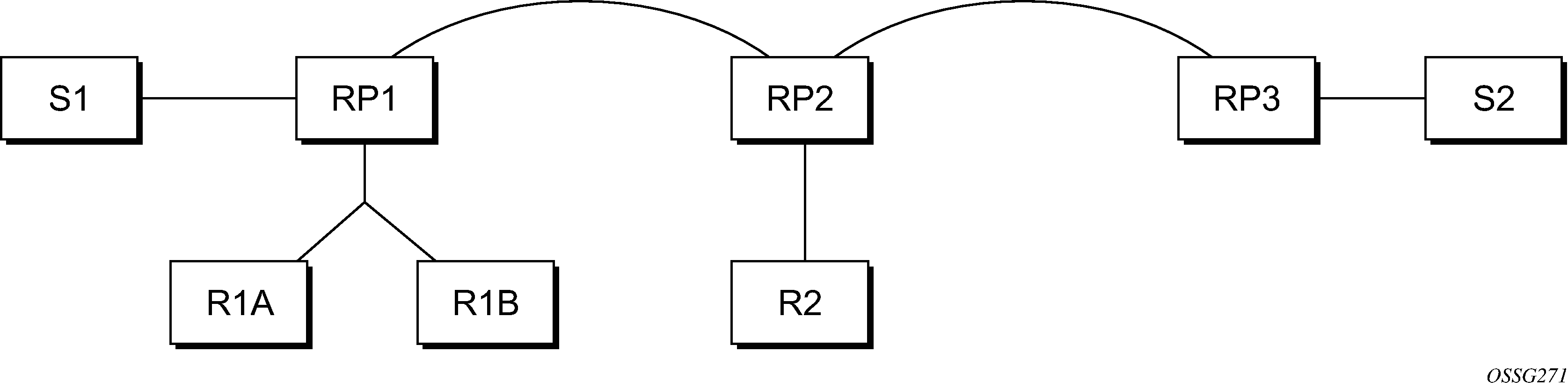
Assume the scenario in Anycast RP for PIM-SM implementation example is completely connected where R1A, R1B, and R2 are receivers for a group, and S1 and S2 send to that group. Assume RP1, RP2, and RP3 are all assigned the same IP address which is used as the Anycast-RP address (for example, the IP address is RPA).
The following procedure is used when S1 starts sourcing traffic:
S1 sends a multicast packet.
The DR directly attached to S1 forms a PIM register message to send to the Anycast-RP address (RPA). The unicast routing system delivers the PIM register message to the nearest RP, in this case RP1A.
RP1 receives the PIM register message, de-encapsulates it, and sends the packet down the shared-tree to get the packet to receivers R1A and R1B.
RP1 is configured with RP2 and RP3’s IP address. Because the register message did not come from one of the RPs in the anycast-RP set, RP1 assumes the packet came from a DR. If the register message is not addressed to the Anycast-RP address, an error has occurred and it should be rate-limited logged.
RP1 sends a copy of the register message from S1’s DR to both RP2 and RP3. RP1 uses its own IP address as the source address for the PIM register message.
RP1 may join back to the source-tree by triggering a (S1,G) Join message toward S1; however, RP1 must create (S1,G) state.
RP2 receives the register message from RP1, de-encapsulates it, and also sends the packet down the shared-tree to get the packet to receiver R2.
RP2 sends a register-stop message back to the RP1. RP2 may wait to send the register-stop message if it decides to join the source-tree. RP2 should wait until it has received data from the source on the source-tree before sending the register-stop message. If RP2 decides to wait, the register-stop message is sent when the next register is received. If RP2 decides not to wait, the register-stop message is sent now.
RP2 may join back to the source-tree by triggering a (S1,G) Join message toward S1; however, RP2 must create (S1,G) state.
RP3 receives the register message from RP1, de-encapsulates it, but because there are no receivers joined for the group, it can discard the packet.
RP3 sends a register-stop message back to the RP1.
RP3 creates (S1,G) state so when a receiver joins after S1 starts sending, RP3 can join quickly to the source-tree for S1.
RP1 processes the register-stop message from each of RP2 and RP3. RP1 may cache on a per-RP/per-(S,G) basis the receipt of register-stop message messages from the RPs in the anycast-RP set. This option is performed to increase the reliability of register message delivery to each RP. When this option is used, subsequent register messages received by RP1 are sent only to the RPs in the Anycast-RP set which have not previously sent register-stop message messages for the (S,G) entry.
RP1 sends a register-stop message back to the DR the next time a register message is received from the DR and (when the option in the last bullet is in use) if all RPs in the Anycast-RP set have returned register-stop messages for a particular (S,G) route.
The procedure for S2 sending follows the same steps as above, but it is RP3 which sends a copy of the register originated by S2’s DR to RP1 and RP2. Therefore, this example shows how sources anywhere in the domain, associated with different RPs, can reach all receivers, also associated with different RPs, in the same domain.
Distributing PIM joins over multiple ECMP paths
Commonly used multicast load-balancing method is per bandwidth/round robin, but the interface in an ECMP set can also be used for a particular channel to be predictable without knowing anything about the other channels using the ECMP set.
The mc-ecmp-hashing-enabled command enables PIM joins to be distributed over the multiple ECMP paths based on a hash of S and G. When a link in the ECMP set is removed, the multicast streams that were using that link are re-distributed over the remaining ECMP links using the same hash algorithm. When a link is added to the ECMP set, new joins may be allocated to the new link based on the hash algorithm. Existing multicast streams using the other ECMP links stay on those links until they are pruned, unless the rebalance option is specified.
The default is no mc-ecmp-hashing-enabled, which means that the use of multiple ECMP paths (if enabled at the config>service>vprn context) is controlled by the existing implementation and CLI commands, that is, mc-ecmp-balance.
The mc-ecmp-hashing-enabled command and the mc-ecmp-balance command cannot be used together in the same context.
To achieve distribution of streams across the ECMP links, the hashing steps are as follows:
For a specific (S,G) get all possible next hops.
Sort these next hops based on next hop’s address.
XOR S and G addresses.
Hash the XORed address over the number of PIM next hops.
Use the hash value obtained in step 4, and set that element in the sorted list that was obtained in step 2 as the preferred next hop.
If this element is not available or is not a PIM next hop (PIM neighbor), the next available next hop is chosen.
The following example displays PIM status indicating ECMP hashing is disabled:
*B:BB# show router 100 pim status

===============================================================================
PIM Status ipv4
===============================================================================
Admin State                       : Up
Oper State                        : Up

IPv4 Admin State                  : Up
IPv4 Oper State                   : Up

BSR State                         : Accept Any

Elected BSR
    Address                       : None
    Expiry Time                   : N/A
    Priority                      : N/A
    Hash Mask Length              : 30
    Up Time                       : N/A
    RPF Intf towards E-BSR        : N/A

Candidate BSR
    Admin State                   : Down
    Oper State                    : Down
    Address                       : None
    Priority                      : 0
    Hash Mask Length              : 30

Candidate RP
    Admin State                   : Down
    Oper State                    : Down
    Address                       : 0.0.0.0
    Priority                      : 192
    Holdtime                      : 150

SSM-Default-Range                 : Enabled
SSM-Group-Range
    None

MC-ECMP-Hashing                   : Disabled

Policy                            : None

RPF Table                         : rtable-u

Non-DR-Attract-Traffic            : Disabled
===============================================================================

----------------------------------------------
*B:BB>config>service>vprn>pim# no mc-ecmp-balance mc-ecmp-balance mc-ecmp-balance-
hold
*B:BB>config>service>vprn>pim# no mc-ecmp-balance
*B:BB>config>service>vprn>pim# mc-ecmp-mc-ecmp-balance mc-ecmp-balance-hold mc-ecmp-
hashing-enabled
*B:BB>config>service>vprn>pim# mc-ecmp-hashing-enabled
*B:BB>config>service>vprn>pim# info
----------------------------------------------
                apply-to all
                rp
                    static
                        address 10.3.3.3
                            group-prefix 224.0.0.0/4
                        exit
                    exit
                    bsr-candidate
                        shutdown
                    exit
                    rp-candidate
                        shutdown
                    exit
                exit
                no mc-ecmp-balance
                mc-ecmp-hashing-enabled
----------------------------------------------
*B:BB>config>service>vprn>pim#
apply-to        - Create/remove interfaces in PIM
 [no] import          - Configure import policies
 [no] interface       + Configure PIM interface
 [no] mc-ecmp-balance - Enable/
Disable multicast balancing of traffic over ECMP links
 [no] mc-ecmp-balanc* - Configure hold time for multicast balancing over ECMP links
 [no] mc-ecmp-hashin* - Enable/
Disable hash based multicast balancing of traffic over ECMP links
 [no] non-dr-attract* - Enable/disable attracting traffic when not DR
      rp              + Configure the router as static or Candidate-RP
 [no] shutdown        - Administratively enable or disable the operation of PIM
 [no] spt-switchover* -
 Configure shortest path tree (spt tree) switchover threshold for a group prefix
 [no] ssm-default-ra* - Enable the disabling of SSM Default Range
 [no] ssm-groups      + Configure the SSM group ranges
The following example shows distribution of PIM joins over multiple ECMP paths.
*A:BA# show router 100 pim group

===============================================================================
PIM Groups ipv4
===============================================================================
Group Address                           Type     Spt Bit Inc Intf       No.Oifs
   Source Address                          RP
-------------------------------------------------------------------------------
239.1.1.1                               (S,G)    spt     to_C0          1
   172.0.100.33                            10.20.1.6
239.1.1.2                               (S,G)    spt     to_C3          1
   172.0.100.33                            10.20.1.6
239.1.1.3                               (S,G)    spt     to_C2          1
   172.0.100.33                            10.20.1.6
239.1.1.4                               (S,G)    spt     to_C1          1
   172.0.100.33                            10.20.1.6
239.1.1.5                               (S,G)    spt     to_C0          1
   172.0.100.33                            10.20.1.6
239.1.1.6                               (S,G)    spt     to_C3          1
   172.0.100.33                            10.20.1.6

239.2.1.1                               (S,G)    spt     to_C0          1
   172.0.100.33                            10.20.1.6
239.2.1.2                               (S,G)    spt     to_C3          1
   172.0.100.33                            10.20.1.6
239.2.1.3                               (S,G)    spt     to_C2          1
   172.0.100.33                            10.20.1.6
239.2.1.4                               (S,G)    spt     to_C1          1
   172.0.100.33                            10.20.1.6
239.2.1.5                               (S,G)    spt     to_C0          1
   172.0.100.33                            10.20.1.6
239.2.1.6                               (S,G)    spt     to_C3          1
   172.0.100.33                            10.20.1.6

239.3.1.1                               (S,G)    spt     to_C0          1
   172.0.100.33                            10.20.1.6
239.3.1.2                               (S,G)    spt     to_C3          1
   172.0.100.33                            10.20.1.6
239.3.1.3                               (S,G)    spt     to_C2          1
   172.0.100.33                            10.20.1.6
239.3.1.4                               (S,G)    spt     to_C1          1
   172.0.100.33                            10.20.1.6
239.3.1.5                               (S,G)    spt     to_C0          1
   172.0.100.33                            10.20.1.6
239.3.1.6                               (S,G)    spt     to_C3          1
   172.0.100.33                            10.20.1.6

239.4.1.1                               (S,G)    spt     to_C0          1
   172.0.100.33                            10.20.1.6
239.4.1.2                               (S,G)    spt     to_C3          1
   172.0.100.33                            10.20.1.6
239.4.1.3                               (S,G)    spt     to_C2          1
   172.0.100.33                            10.20.1.6
239.4.1.4                               (S,G)    spt     to_C1          1
   172.0.100.33                            10.20.1.6
239.4.1.5                               (S,G)    spt     to_C0          1
   172.0.100.33                            10.20.1.6
239.4.1.6                               (S,G)    spt     to_C3          1
   172.0.100.33                            10.20.1.6
-------------------------------------------------------------------------------
Groups : 24
===============================================================================
PIM interface on IES subscriber group interfaces
PIM on a subscriber group interface allows for SAP-level replication over an ESM Group interface by establishing PIM adjacency to a downstream router. PIM interface on IES subscriber group interface depicts the model:
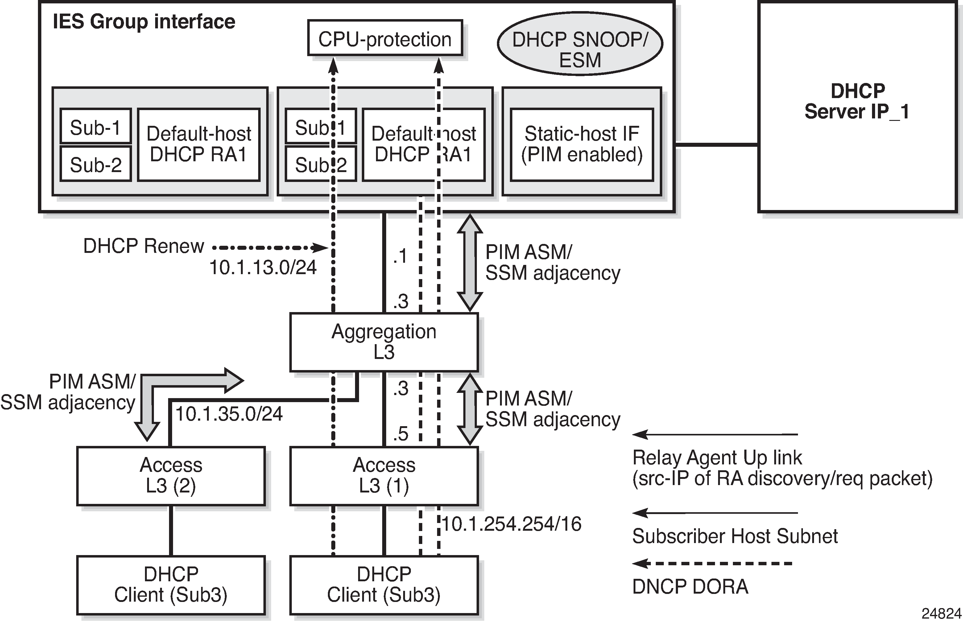
On an IES subscriber-interface, an Ethernet SAP is configured (LAG or physical port). On the SAP, a static-host is configured for connectivity to downstream Layer 3 aggregation devices (including PIM adjacency) while multiple default-hosts can be configured for subscriber traffic. Single SAP with a single static-host per group interface is supported to establish PIM adjacency on a subscriber group interface. Both IPv4 PIM ASM and SSM are supported.
Feature restrictions:
Only IPv4 PIM is supported with a single static host used to form a PIM interface under a group interface. Using multiple hosts or non-static hosts is not supported. Configuring IPv6-related parameters in config>router>pim>interface group-ift is not blocked, but takes no effect.
config>router>pim>apply-to configuration does not apply to PIM interfaces on IES subscriber group interfaces.
PIM on group interfaces is not supported in VPRN context.
Extranet is not supported.
Locally attached receivers are not supported (no IGMP/MLD and PIM mix in OIF list).
Default anti-spoofing must be configured (IP+MAC).
A subscriber profile with pim-policy enabled cannot combine with the following policies (config>subscr-mgmt>sub-prof):
- no host-tracking
- apply a host tracking policy
- no igmp-policy
- apply an IGMP policy
- no mld-policy
- apply an MLD policy
- no nat-policy
- apply a NAT policy
- no sub-mcac-policy
- apply a subscriber MCAC policy (MCAC policy can be used when configured in PIM interface context)
The feature is supported on IOM3-XP or newer line cards. When enabling the feature on older hardware, joins may be accepted and an outgoing interface may be created for the group, but traffic is not sent out on egress because no OIF is created in forwarding.
MoFRR
With large scale multicast deployments, a link or nodal failure impacts multiple subscribers or a complete region or segment of receivers. This failure interrupts the receiver client experience. Besides the impact on user experience, though multicast client applications may buffer streams for short period of time, the loss of stream data may trigger unicast request for the missing stream data to the source in specific middleware implementations. Those requests can overload the network resources, if a traffic loss persists for a prolonged period.
To minimize service interruption to end-users and protect the network from sudden surge of unicast requests, SR OS implements a fast failover scheme for native IP networks. SR OS Multicast-Only Fast Reroute (MoFRR) implementation is based on RFC 7431, Multicast-Only Fast Reroute, and relies on:
sending a join to a primary and a single standby upstream nodes over disjoined paths
fast failover to a standby stream upon detection of a failure
The functionality relies on failure detection on the primary path to switch to forwarding the traffic from the standby path. The traffic failure can happen with or without physical links or nodes going down. Various mechanisms for link or node failure detections are supported; however, to achieve best performance and resilience, it is recommended to enable MoFRR on every node in the network and use hop-by-hop BFD for fast link failure or data plane failure detection on each upstream link. Without BFD, the PIM adjacency loss or route change could be used to detect traffic failure. MoFRR steady state no failure and MoFRR switch to standby stream on a link failure depict MoFRR behavior.


MoFRR functionality supports the following:
IPv4 or IPv6 link or node failure protection in global routing instance
Rosen PIM-SSM with MDT SAFI
active streams and a single standby stream over disjoint ECMP paths
active streams and a single standby stream joins over IS-IS or OSPF Loop-Free Alternate paths
all regular PIM interfaces supporting MoFRR for all multicast streams (tunnel interfaces are ignored)
Automatic discovery of group-to-RP mappings (auto-RP)
Auto-RP is a proprietary group discovery and mapping mechanism for IPv4 PIM that is described in cisco-ipmulticast/pim-autorp-spec, Auto-RP: Automatic discovery of Group-to-RP mappings for IP multicast. The functionality is similar to the IETF standard bootstrap router (BSR) mechanism that is described in RFC 5059, Bootstrap Router (BSR) Mechanism for Protocol Independent Multicast (PIM), to dynamically learn about the availability of Rendezvous Points (RPs) in a network. When a router is configured as an RP-mapping agent with the pim>rp>auto-rp-discovery command, it listens to the CISCO-RP-ANNOUNCE (224.0.1.39) group and caches the announced mappings. The RP-mapping agent then periodically sends out RP-mapping packets to the CISCO-RP-DISCOVERY (224.0.1.40) group. PIM dense-mode (PIM-DM) as described in RFC 3973, Protocol Independent Multicast - Dense Mode (PIM-DM): Protocol Specification (Revised), is used for the auto-RP groups to support multihoming and redundancy. The RP-mapping agent supports announcing, mapping, and discovery functions; candidate RP functionality is not supported. SR OS supports version 1 of the Auto-RP specification; the ability to deny RP-mappings by advertising negative group prefixes is not supported.
Auto-RP is supported for IPv4 in multicast VPNs and in the global routing instance. Either BSR or auto-RP for IPv4 can be configured; the two mechanisms cannot be enabled together. BSR for IPv6 and auto-RP for IPv4 can be enabled together. In a multicast VPN, auto-RP cannot be enabled together with sender-only or receiver-only multicast distribution trees (MDTs), or wildcard S-PMSI configurations that could block flooding.
VRRP aware PIM
The Virtual Router Redundancy Protocol (VRRP) eliminates the single point of failure inherent in the static default-routed environment. VRRP describes a method of implementing a redundant IP interface that provides dynamic failover if the VRRP master router (MR) becomes unavailable.
VRRP provides information about the state of a router. However, PIM operates independently of VRRP group states. The PIM DR and the VRRP MR may not be the same router and IP multicast traffic may not necessarily follow the same path as elected by VRRP.
To leverage the redundancy capabilities of VRRP that are lacking in PIM, the VRRP Aware PIM mechanism allows PIM to monitor and react to changes in the VRRP MR. This ensures that the multicast traffic follows the unicast traffic through the same gateway as the VRRP MR, providing consistent IP multicast forwarding in a redundant network.
Configuring VRRP aware PIM
The VRRP Aware PIM feature enables PIM to track the state of a VRRP instance and to identify whether the associated VRRP interface is the master. PIM uses an operational group parameter (oper-group group-name) to monitor the state of VRRP. One operational group can be created for IPv4, and another for IPv6. When VRRP is the MR, the operational group is up; for all other VRRP states, the operational group is down. A VRRP instance can only be associated with one operational group, and an operational group can have one or more associated VRRP instances. This feature is supported on base router, IES, and VPRN interfaces.
If the monitored interface is the VRRP MR, PIM becomes the DR by setting its priority to the configured oper-group-active-priority value. For the router to become the DR, the correct priorities must be configured so that the oper-group-active-priority is the highest priority on the IP interface.
If a PIM router is the DR and then receives an indication from VRRP that the interface is no longer the VRRP MR, PIM relinquishes the DR role by setting its priority back to the default or configured priority value.
If the configured VRRP instance or oper-group is not configured, PIM operates as normal with the default or configured priority value, and does not set its priority to oper-group-active-priority. A change in the operational group status is independent of the address family; IPv4 and IPv6 priorities are configured independently of each other. Two operational groups are supported per PIM interface, one for IPv4 and one for IPv6.
Configuration recommendations
When configuring VRRP Aware PIM, consider the following recommendations:
VRRP could be configured to use BFD to speed up failure detection in addition to the functionality provided by VRRP Aware PIM.
To optimize failover, the config>router>pim>non-dr-attract-traffic command can be enabled on the primary and secondary routers to make them a hot-standby redundant pair. This configuration ignores the DR state and attracts traffic to populate the router’s PIM database. This setting should not be used if multicast traffic must only follow the VRRP MR.
The config>service>oper-group>hold-time>group>up time on the primary router and config>service>oper-group>hold-time>group>down time on the secondary router should both be set to the time needed to repopulate the PIM database; for example, 10 seconds. This allows the primary router to populate its PIM database again before becoming the DR if a failure occurs from the primary to secondary router, and recover from the secondary back to the primary router.
The config>service>oper-group>hold-time>group>up time should be set to 0 on the secondary router so that it assumes the DR role immediately if the primary router fails. The up hold time is set to 4 seconds by default, which delays the DR change unnecessarily.
The sticky DR setting should be disabled if it is configured with the config>router>pim>if>sticky-dr command. Sticky DR enables the secondary router to continue to act as the DR after the primary router comes back up. Sticky DR is incompatible with the VRRP Aware PIM mechanism that tracks the VRRP MR.
The following is a basic configuration example for VRRP Aware PIM.
service
    oper-group ‟VAwP1” create
    exit
vprn 1 customer 1 create
    interface to-LAN
        vrrp 1 create
            oper-group ‟VAwP1”
        exit
   pim
       interface to-LAN
           monitor-oper-group ‟VAwP1” family ipv4 add 90
           monitor-oper-group ‟VAwP1” family ipv6 add 90
       exit
       interface to-LAN2
           monitor-oper-group ‟VAwP1” family ipv4 add 90
           monitor-oper-group ‟VAwP2” family ipv6 set 90
       exit
   exit
exit
Primary router example
*B:Dut-C>config>service# info
----------------------------------------------
        oper-group "vrrp1_1" create
            hold-time
                group up 10
            exit
        exit
        oper-group "vrrp1_1_ipv6" create
            hold-time
                group up 10
            exit
        exit
        customer 1 create
            description "Default customer"
        exit
        vprn 1 customer 1 create
            interface "toRemoteSite_1001" create
                address 10.1.1.5/24
                bfd 500 receive 500 multiplier 3
                vrrp 1
                    backup 10.1.1.100
                    priority 200
                    ping-reply
                    message-interval 5
                    oper-group "vrrp1_1"
                    bfd-enable 1 interface "toRemoteSite_1001" dst-ip 10.1.1.4
                exit
                ipv6
                    address 2001:db8:1:1:1:5/112
                    link-local-address ff00:db8:1:1:1:5 preferred
                    bfd 500 receive 500 multiplier 3
                    vrrp 1
                        backup ff00:db8:1:1:1:100
                        priority 200
                        ping-reply
                        message-interval 5
                        oper-group "vrrp1_1_ipv6"
                        bfd-enable 1 interface "toRemoteSite_1001"
dst-ip 2001:db8:1:1:1:4
                    exit
                exit
            exit
            interface "toDC" create
                address 10.1.30.5/24
                bfd 500 receive 500 multiplier 3
                vrrp 255
                    backup 10.1.30.100
                    priority 200
                    policy 1
                    ping-reply
                    message-interval 5
                    bfd-enable 1 interface "toDC" dst-ip 10.1.30.4
                exit
                ipv6
                    address 2001::db8:1:30:5/112
                    link-local-address ff00:db8:30:1:30:5 preferred
                    bfd 500 receive 500 multiplier 3
                    vrrp 255
                        backup ff00:db8:30:1:30:100
                        priority 200
                        policy 1001
                        ping-reply
                        message-interval 5
                        bfd-enable 1 interface "toDC" dst-ip 2001::db8:1:30:4
                    exit
                exit
                sap 2/1/2:1 create
                exit
            exit
            router-advertisement
                interface "toRemoteSite_1001"
                    use-virtual-mac
                    no shutdown
                exit
                interface "toDC"
                    use-virtual-mac
                    no shutdown
                exit
            exit
            igmp
                interface "toDC"
                    no shutdown
                exit
                no shutdown
            exit
            mld
                interface "toDC"
                    no shutdown
                exit
                no shutdown
            exit
            pim
                no ipv6-multicast-disable
                interface "toRemoteSite_1001"
                    monitor-oper-group "vrrp1_1" family ipv4 set 5
                    monitor-oper-group "vrrp1_1_ipv6" family ipv6 set 5
                exit
                interface "toDC"
                    monitor-oper-group "vrrp1_1" family ipv4 set 5
                    monitor-oper-group "vrrp1_1_ipv6" family ipv6 set 5
                exit
                rp
                    static
                        address 10.1.10.245
                            group-prefix 224.0.0.0/4
                        exit
                    exit
                    bsr-candidate
                        shutdown
                    exit
                    rp-candidate
                        shutdown
                    exit
                    ipv6
                        static
                            address 2001:db8:1:10:245
                                group-prefix ff00:db8::/8
                            exit
                        exit
                    exit
                exit
                non-dr-attract-traffic
                no shutdown
            exit
            no shutdown
        exit
Secondary router example
*B:Dut-E>config>service# info
----------------------------------------------
        oper-group "vrrp1_1" create
            hold-time
                group down 10
                group up 0
            exit
        exit
        oper-group "vrrp1_1_ipv6" create
            hold-time
                group down 10
                group up 0
            exit
        exit
        customer 1 create
            description "Default customer"
        exit
        vprn 1 customer 1 create
            snmp
                community "XldhYQtqb7c" hash2 rw version both
            exit
            route-distinguisher 10.1.10.244:1
            interface "system" create
                address 10.1.10.244/32
                ipv6
                    address 2001:db8:1:10:244/128
                exit
                loopback
            exit
            interface "toRemoteSite_1001" create
                address 10.1.1.4/24
                ip-mtu 1454
                bfd 500 receive 500 multiplier 3
                vrrp 1
                    backup 10.1.1.100
                    ping-reply
                    standby-forwarding
                    message-interval 5
                    oper-group "vrrp1_1"
                    bfd-enable 1 interface "toRemoteSite_1001" dst-ip 10.1.1.5
                exit
                ipv6
                    address 2001:db8:1:1:4/112
                    link-local-address ff00:db8:1:1:1:4 preferred
                    bfd 500 receive 500 multiplier 3
                    vrrp 1
                        backup ff00:db8:1:1:1:100
                        ping-reply
                        standby-forwarding
                        message-interval 5
                        oper-group "vrrp1_1_ipv6"
                        bfd-enable 1 interface "toRemoteSite_1001"
dst-ip 2001:db8:1:1:5
                    exit
                exit
            exit
            interface "toDC" create
                address 10.1.30.4/24
                bfd 500 receive 500 multiplier 3
                vrrp 255
                    backup 10.1.30.100
                    ping-reply
                    standby-forwarding
                    message-interval 5
                    bfd-enable 1 interface "toDC" dst-ip 10.1.30.5
                exit
                ipv6
                    address 2001:db8:1:30:4/112
                    link-local-address ff00:db8:30:1:30:4 preferred
                    bfd 500 receive 500 multiplier 3
                    vrrp 255
                        backup ff00:db8:30:1:30:100
                        ping-reply
                        standby-forwarding
                        message-interval 5
                        bfd-enable 1 interface "toDC" dst-ip 2001::db8:1:30:5
                    exit
                exit
                sap 1/1/5:1 create
                exit
            exit
            static-route-entry 10.1.10.245/32
                next-hop 10.1.30.5
                    no shutdown
                exit
            exit
            static-route-entry 2001:db8:1:10:245/128
                next-hop 2001:db8:1:30:5
                    no shutdown
                exit
            exit
            router-advertisement
                interface "toRemoteSite_1001"
                    use-virtual-mac
                    no shutdown
                exit
                interface "toDC"
                    use-virtual-mac
                    no shutdown
                exit
            exit
            igmp
                interface "toDC"
                    no shutdown
                exit
                no shutdown
            exit
            mld
                interface "toDC"
                    no shutdown
                exit
                no shutdown
            exit
            pim
                no ipv6-multicast-disable
                interface "toRemoteSite_1001"
                    monitor-oper-group "vrrp1_1" family ipv4 set 255
                    monitor-oper-group "vrrp1_1_ipv6" family ipv6 set 255
                exit
                interface "toDC"
                    monitor-oper-group "vrrp1_1" family ipv4 set 255
                    monitor-oper-group "vrrp1_1_ipv6" family ipv6 set 255
                exit
                rp
                    static
                        address 10.1.10.245
                            group-prefix 224.0.0.0/4
                        exit
                    exit
                    bsr-candidate
                        shutdown
                    exit
                    rp-candidate
                        shutdown
                    exit
                    ipv6
                        static
                            address 2001:db8:1:10:245
                                group-prefix ff00:db8:/8
                            exit
                        exit
                    exit
                exit
                non-dr-attract-traffic
                no shutdown
            exit
            no shutdown
        exit
IPv6 PIM models
IPv6 multicast enables multicast applications over native IPv6 networks. There are two service models: Any Source Multicast (ASM) and Source Specific Multicast (SSM) which includes PIM-SSM and MLD (see MLD overview). SSM does not require source discovery and only supports single source for a specific multicast stream. As a result, SSM is easier to operate in a large scale deployment that uses the one-to-many service model.
PIM SSM
The IPv6 address family for SSM model is supported. This includes the ability to choose which RTM table to use (unicast RTM, multicast RTM, or both). OSPF3, IS-IS and static-route have extensions to support submission of routes into the IPv6 multicast RTM.
System PIM SSM scaling
PIM SSM scaling can be increased to 256k (S,G)s using the pim-ssm-scaling command. This command enables (S,G) scaling for PIM SSM in the global routing table only. The current scaling limitation of (S,G)s per complex (FP) still exist. However, the 256K (S,G)s can be configured over multiple complex to achieve this higher scaling.
When PIM SSM scaling is enabled, the following multicast features are disabled:
DM
MoFRR
JP policy
SSM groups
(S,G) programming is a maximum of 32000 per complex
InBand features (BIER and MLDP)
Extranet
ASM
This feature is only supported on CPM5s.
When this command is enabled and there is a mix of FP3, FP4, and FP5 cards in the system, Nokia recommends that configure mcast-management chassis-level per-mcast-plane-capacity total-capacity be set to dynamic so that the system dynamically chooses the lowest denominator throughput card as multicast plane throughput.
To achieve fast failover when PIM SSM scaling is enabled, the default MCID is used which results in the multicast traffic being sent to all line cards and silently discarded where there is no receiver for that traffic. Consequently, the maximum achievable plane capacity for this traffic is constrained to that of the lowest performance FP. When the maximum link capacity from the fabric to the lowest-performance FP is reached, the link to that FP is overloaded causing the fabric to back-pressure the ingress and resulting in packet loss for all FPs. By using the default MCID, this capacity constraint is independent of whether the lowest-performance FP has a receiver on it or not.
If the multicast management chassis per-plane total capacity is configured to an explicit value which is larger than that supported by the lowest-performance FP, IMPM believes there is more plane capacity available than there really is and the result is (S,G) packet loss instead of blackholing.
By setting the multicast management chassis per-plane total capacity to dynamic, the system automatically sets the switch fabric multicast plane capacity to the minimum value supported by the fabric and all line cards in the system. IMPM then has the correct view of the available plane capacity and correctly blackholes (S,G)s when insufficient plane capacity is available. The total maximum multicast capacity is still constrained by the lowest-performance FP.
PIM ASM
IPv6 PIM ASM is supported. All PIM ASM related functions such as bootstrap router, RP, and so on, support both IPv4 and IPv6 address-families. IPv6 specific parameters are configured under config>router>pim>rp>ipv6.
Embedded RP
The detailed protocol specification is defined in RFC 3956, Embedding the Rendezvous Point (RP) Address in an IPv6 Multicast Address. This RFC describes a multicast address allocation policy in which the address of the RP is encoded in the IPv6 multicast group address, and specifies a PIM-SM group-to-RP mapping to use the encoding, leveraging, and extending unicast-prefix-based addressing. This mechanism not only provides a simple solution for IPv6 inter-domain ASM but can be used as a simple solution for IPv6 intra-domain ASM with scoped multicast addresses as well. It can also be used as an automatic RP discovery mechanism in those deployment scenarios that would have previously used the Bootstrap Router protocol (BSR).
PIM signaling over BIER
PIM signaling over BIER provides a mechanism to signal PIM join and prune messages through a BIER domain with minimal disruption to the PIM domain routers. The Ingress BIER Boundary Routers (IBBRs) terminate PIM and forward the PIM joins and prunes through the BIER domain to egress at the Egress BIER Boundary Router (EBBR). The EBBR is the closest BIER router to the source.
The PIM signaling messages arriving at the IBBR are encapsulated in a BIER header and forwarded to the EBBR. The EBBR tracks every IBBR that is interested in a specific (S,G). The EBBR forwards the join and prune messages to the PIM domain to which it is attached. When the source receives a join message, it starts the multicast flow for this (S,G). When these PDUs arrive on the EBBR, the EBBR notes all IBBRs that are interested in the (S,G) and adds the IBBRs’ corresponding BIER bits to the BIER header. The EBBR (BFIR) forwards the BIER packets with the PDU as payload to the IBBRs (BFERs), where the BIER header is removed and the packet is forwarded on the interface where the join (S,G) was received.
The following restrictions apply:
PIM signaling through a BIER domain is only supported on FP4 and FP5.
PIM signaling through a BIER domain is only supported with SSM and not with ASM.
PIM signaling through a BIER domain and MLDP-inband and GTM are mutually exclusive.
EBBR discovery
For the EBBR to be discovered, the EBBR must be the source of the route for the multicast source. This means that the EBBR has to generate the multicast source route and advertise it using IGP in one of the following ways:
single area
- The EBBR is directly connected to the multicast source and therefore is the source of the multicast source route.
- The EBBR has a static route for the multicast source and redistributes this into IGP. Consequently, it becomes the source of the route for the multicast source.
multiple areas
- The EBBR is an ABR and re-advertises the multicast source, making the EBBR the source of that route. In this case, the IBBR must be in the same area.
- The EBBR is an ASBR, and the IBBR has to be in the same AS and area as the EBBR.
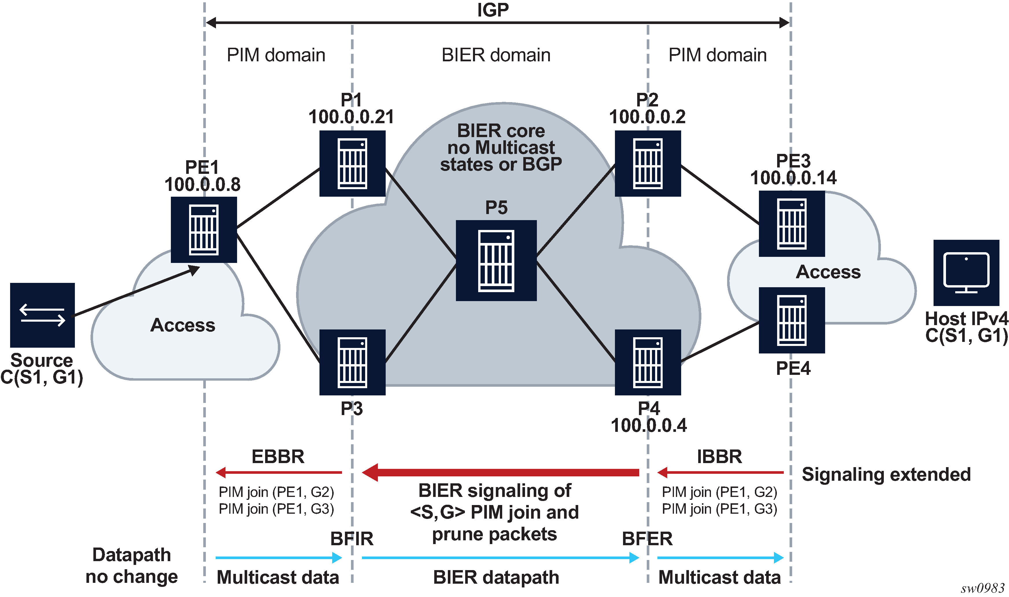
Single area scenario
Single area PIM signaling over BIER scenario shows a scenario in which the PIM domains and the BIER domain (including the source and the hosts) are all in a single area. The source can be directly connected to the EBBR. In this case, the EBBR is the source of the route for multicast source, or on the EBBR a static route can be configured for the multicast source and this is re-distributed into the IGP.
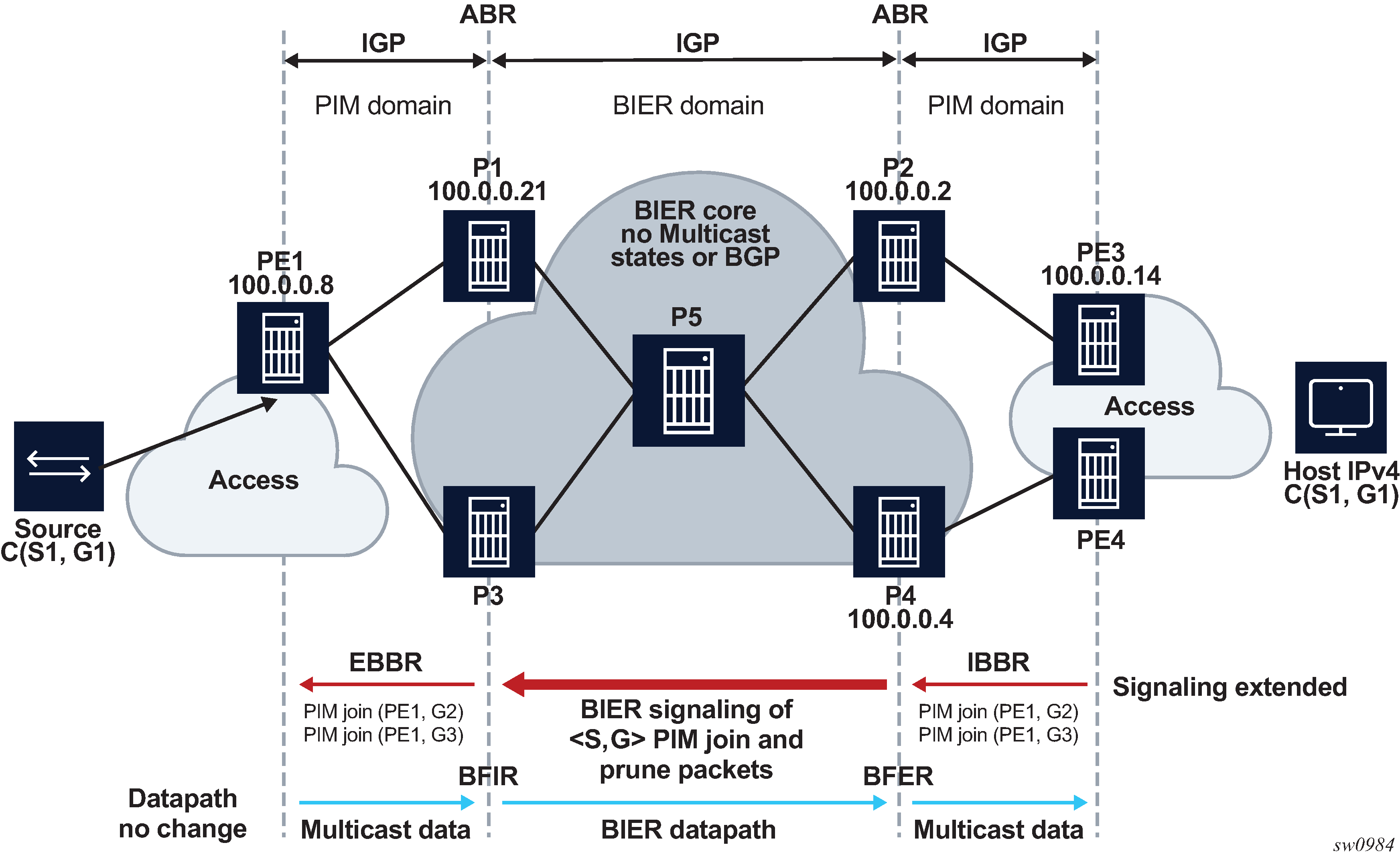
Multiple area scenarios
Multiple area PIM signaling over BIER scenario - core area shows a scenario in which the EBBR and IBBR are part of the core (backbone) area.
As in the single area scenario, the IBBR attempts to resolve the source IP address, and the IGP calculates the SPF tree to the source. IGP finds that the source IP address (S1) is generated using ABR routers P1 or P3 because these routers are the source routers for S1.
If the EBBR is not the ABR router, the rules of the single area scenario persists and a static route to the multicast source is required. If the EBBR is an ABR, a static route is not required.
Multiple area PIM signaling over BIER scenario - core AS shows a scenario in which the BIER domain is in the core AS instead of the core area. The core AS consists of a single area.
The EBBR and IBBRs can be any router in the core AS/area. BGP redistributes its routes into the IGP routers P1, P2, P3, and P4.

PIM signaling support
PIM signaling is supported only in the SD0.
When a PIM join or prune message arrives on the IBBR, the source is resolved only in the SD0 IGP Multi-instance. For example, if SD0 is assigned to MT IPv4-Unicast the source of the PIM message is resolved only in the MT0.
On the EBBR, only SD0 is supported, so if any PIM signaling messages arrive on the EBBR on any other SD other than SD0 they are not processed.
The PIM join attribute uses attribute type 7.
PIM signaling MTU considerations
The following considerations apply to signaling Rosen MVPN PIM packets over a BIER core.
The MTU of Rosen MVPN tunnels is hardcoded to 1468. For each MVPN, the PIM joins are packed into a single packet up to a size of 1468 bytes. MVPN signaling does not take into account the BIER header size when the Rosen tunnels are signaled over the BIER domain.
The configure service vprn pim mtu-over-head mtu-value command reduces the Rosen tunnel MTU to allow a BIER header to be added without exceeding the network MTU. The tunnel MTU is reduced by the number of bytes specified by the mtu-value parameter of the mtu-over-head command.
PIM auto-RP full support
The auto-RP protocol consists of announcing, mapping, and discovery functions. The Internet Assigned Numbers Authority (IANA) has assigned two group addresses, 224.0.1.39 and 224.0.1.40, for auto-RP.
Three roles can be configured in auto-RP:
candidate RP (CRP)
The candidate RP is a router that aims to be an RP for a multicast group using RP-announce messages.
mapping agent
The mapping agent sees the RP-announce messages and selects the best RP based on the highest IP address for the advertised multicast group. Then, it floods the network with RP-mapping messages about which RPs to use for that group.
auto-RP listener
The auto-RP listener forwards traffic about the multicast group throughout the network so that the routers that are not directly attached to the mapping agent or to the RP can also learn the RP address. When the listener functionality is enabled, the router uses dense mode only for the two dedicated multicast group addresses.
SR OS supports all auto-RP functionality under GRT and MVPN (NG-MVPN and Rosen MVPN with BGP SAFI).
Candidate RP considerations
The candidate RP address needs to be set correctly to the system IP or a loopback IP address. The candidate RP group-range is optional. If it is not set, the default 224.0.0.0/4 group is advertised.
Timer considerations
SR OS sends the RP-announce messages by default every 60 seconds with the holdtime that is configured for the candidate-RP, set to 150 seconds. The default time of 60 seconds for the RP-announce messages can be modified by changing the RP-candidate holdtime ((holdtime)*2)/5).
SR OS sends the RP-mapping messages by default every 60 seconds with the holdtime set to 181 seconds. The default time of 60 seconds for the RP-mapping messages is fixed and cannot be modified.
Configuring PIM with CLI
This section provides information to configure PIM using the command line interface.
PIM configuration overview
PIM is not enabled by default. When PIM is enabled, data is forwarded to network segments with active receivers that have explicitly requested the multicast group. When enabled, at least one interface must be specified in the PIM context as PIM is an interface function. Creating an interface enables PIM.
Basic PIM configuration
Perform the following basic PIM configuration tasks:
-
Enable PIM (required)
-
Add interfaces so the protocol establishes adjacencies with the neighboring routers (required)
-
Configure a way to calculate group-to-RP mapping (required) by either:
-
static group-to-RP mapping
-
enabling Candidate RP/Bootstrap mechanism on some routers
-
-
Enable unicast routing protocols to learn routes toward the RP/source for reverse path forwarding (required)
-
Add SSM ranges (optional)
-
Enable Candidate BSR (optional)
-
Enable Candidate RP (optional)
-
Change hello interval (optional)
-
Configure route policies (bootstrap-export, bootstrap-import, import join and register)
Configuring PIM parameters
Enabling PIM
When configuring PIM, make sure to enable PIM on all interfaces for the routing instance, otherwise multicast routing errors can occur.
Use the following CLI syntax to enable PIM.
config>router# pim
The following example displays the detailed output when PIM is enabled.
A:LAX>>config>router# info detail
...
#------------------------------------------
echo "PIM Configuration"
#------------------------------------------
        pim
            no import join-policy
            no import register-policy
            apply-to none
            rp
                no bootstrap-import
                no bootstrap-export
                static
                exit
                bsr-candidate
                    shutdown
                    priority 0
                    hash-mask-len 30
                    no address
                exit
                rp-candidate
                    shutdown
                    no address
                    holdtime 150
                    priority 192
                exit
            exit
            no shutdown
        exit
#------------------------------------------
...
A:LAX>>config>system#
Configuring PIM interface parameters
The following example displays the command usage to configure PIM interface parameters:
A:LAX>config>router# pim
    — A:LAX>config>router>pim# interface "system"
    — A:LAX>config>router>pim>if# exit
    — A:LAX>config>router>pim# interface "lax-vls"
    — A:LAX>config>router>pim>if# exit
    — A:LAX>config>router>pim# interface "lax-sjc"
    — A:LAX>config>router>pim>if# exit
    — A:LAX>config>router>pim# interface "p1-ix"
    — A:LAX>config>router>pim>if# exit
    — A:LAX>config>router>pim# rp
    — A:LAX>config>router>pim>rp# static
    — A:LAX>config>router>pim>rp>static# address 239.22.187.237
    — A:LAX>config>router>..>address# group-prefix 239.24.24.24/32
    — A:LAX>config>router>pim>rp>static>address# exit
    — A:LAX>config>router>pim>rp>static# exit
    — A:LAX>config>router>pim>rp# exit
    — A:LAX>config>router>pim#
The following example displays the PIM configuration:
A:LAX>config>router>pim# info
----------------------------------------------
            interface "system"
            exit
            interface "lax-vls"
            exit
            interface "lax-sjc"
            exit
            interface "p1-ix"
            exit
            rp
                static
                    address 239.22.187.237
                        group-prefix 239.24.24.24/32
                    exit
                    address 10.10.10.10
                    exit
                exit
                bsr-candidate
                    shutdown
                exit
                rp-candidate
                    shutdown
                exit
            exit
----------------------------------------------
A:LAX>config>router>pim#
A:SJC>config>router# pim
    — A:SJC>config>router>pim# interface "system"
    — A:SJC>config>router>pim>if# exit
    — A:SJC>config>router>pim# interface "sjc-lax"
    — A:SJC>config>router>pim>if# exit
    — A:SJC>config>router>pim# interface "sjc-nyc"
    — A:SJC>config>router>pim>if# exit
    — A:SJC>config>router>pim# interface "sjc-sfo"
    — A:SJC>config>router>pim>if# exit
    — A:SJC>config>router>pim# rp
    — A:SJC>config>router>pim>rp# static
    — A:SJC>config>router>pim>rp>static# address 239.22.187.237
    — A:SJC>config>router>pim>rp>static>address# group-prefix 239.24.24.24/32
    — A:SJC>config>router>pim>rp>static>address# exit
    — A:SJC>config>router>pim>rp>static# exit
    — A:SJC>config>router>pim>rp# exit
    — A:SJC>config>router>pim#
A:SJC>config>router>pim# info
----------------------------------------------
            interface "system"
            exit
            interface "sjc-lax"
            exit
            interface "sjc-nyc"
            exit
            interface "sjc-sfo"
            exit
            rp
                static
                    address 239.22.187.237
                        group-prefix 239.24.24.24/32
                    exit
                exit
                bsr-candidate
                    shutdown
                exit
                rp-candidate
                    shutdown
                exit
            exit
----------------------------------------------
A:SJC>config>router>pim#
A:MV>config>router# pim
    — A:MV>config>router>pim# interface "system"
    — A:MV>config>router>pim>if# exit
    — A:MV>config>router>pim# interface "mv-sfo"
    — A:MV>config>router>pim>if# exit
    — A:MV>config>router>pim# interface "mv-v1c"
    — A:MV>config>router>pim>if# exit
    — A:MV>config>router>pim# interface "p3-ix"
    — A:MV>config>router>pim>if# exit
    — A:MV>config>router>pim# rp
    — A:MV>config>router>pim>rp# static
    — A:MV>config>router>pim>rp>static# address 239.22.187.237
    — A:MV>config>router>pim>rp>static>address# group-prefix 239.24.24.24/32
    — A:MV>config>router>pim>rp>static>address# exit
    — A:MV>config>router>pim>rp>static#
    — A:MV>config>router>pim>rp# exit
    — A:MV>config>router>pim#
A:MV>config>router>pim# info
----------------------------------------------
            interface "system"
            exit
            interface "mv-sfo"
            exit
            interface "mv-vlc"
            exit
            interface "p3-ix"
            exit
            rp
                static
                    address 239.22.187.237
                        group-prefix 239.24.24.24/32
                    exit
                exit
                bsr-candidate
                    address 2.22.187.236
                    no shutdown
                exit
                rp-candidate
                    address 2.22.187.236
                    no shutdown
                exit
            exit
----------------------------------------------
A:MV>config>router>pim#
A:SFO>config>router# pim
    — A:SFO>config>router>pim# interface "system"
    — A:SFO>config>router>pim>if# exit
    — A:SFO>config>router>pim# interface "sfo-sfc"
    — A:SFO>config>router>pim>if# exit
    — A:SFO>config>router>pim# interface "sfo-was"
    — A:SFO>config>router>pim>if# exit
    — A:SFO>config>router>pim# interface "sfo-mv"
    — A:SFO>config>router>pim>if# exit
    — A:SFO>config>router>pim# rp
    — A:SFO>config>router>pim>rp# static
    — A:SFO>config>router>pim>rp>static# address 239.22.187.237
    — A:SFO>config>router>pim>rp>static>address# group-prefix 239.24.24.24/32
    — A:SFO>config>router>pim>rp>static>address# exit
    — A:SFO>config>router>pim>rp>static# exit
    — A:SFO>config>router>pim>rp # exit
    — A:SFO>config>router>pim#
A:SFO>config>router>pim# info
----------------------------------------------
            interface "system"
            exit
            interface "sfo-sjc"
            exit
            interface "sfo-was"
            exit
            interface "sfo-mv"
            exit
            rp
                static
                    address 239.22.187.237
                        group-prefix 239.24.24.24/32
                    exit
                exit
                bsr-candidate
                    address 239.22.187.239
                    no shutdown
                exit
                rp-candidate
                    address 239.22.187.239
                    no shutdown
                exit
            exit
----------------------------------------------
A:SFO>config>router>pim#
A:WAS>config>router# pim
    — A:WAS>config>router>pim# interface "system"
    — A:WAS>config>router>pim>if# exit
    — A:WAS>config>router>pim# interface "was-sfo"
    — A:WAS>config>router>pim>if# exit
    — A:WAS>config>router>pim# interface "was-vlc"
    — A:WAS>config>router>pim>if# exit
    — A:WAS>config>router>pim# interface "p4-ix"
    — A:WAS>config>router>pim>if# exit
    — A:WAS>config>router>pim# rp
    — A:WAS>config>router>pim>rp# static
    — A:WAS>config>router>pim>rp>static# address 239.22.187.237
    — A:WAS>config>router>pim>rp>static>address# group-prefix 239.24.24.24/32
    — A:WAS>config>router>pim>rp>static>address# exit
    — A:WAS>config>router>pim>rp>static# exit
    — A:WAS>config>router>pim>rp# bsr-candidate
    — A:WAS>config>router>pim>rp>bsr-cand# address 239.22.187.240
    — A:WAS>config>router>pim>rp>bsr-cand# no shutdown
    — A:WAS>config>router>pim>rp>bsr-cand# exit
    — A:WAS>config>router>pim>rp# exit
    — A:WAS>config>router>pim#
A:WAS>config>router>pim# info
----------------------------------------------
            interface "system"
            exit
            interface "was-sfo"
            exit
            interface "was-vlc"
            exit
            interface "p4-ix"
            exit
            rp
                static
                    address 239.22.187.237
                        group-prefix 239.24.24.24/32
                    exit
                exit
                bsr-candidate
                    address 239.22.187.240
                    no shutdown
                exit
                rp-candidate
                    address 239.22.187.240
                    no shutdown
                exit
            exit
----------------------------------------------
A:WAS>config>router>pim#
Configuring PIM join/register policies
Join policies are used in Protocol Independent Multicast (PIM) configurations to prevent the transportation of multicast traffic across a network and the dropping of packets at a scope at the edge of the network. PIM Join filters reduce the potential for denial of service (DoS) attacks and PIM state explosion—large numbers of Joins forwarded to each router on the RPT, resulting in memory consumption. See the Importing PIM Join/Register Policies section of the Multicast Routing Guide for more information.
(*,G) or (S,G) is the information used to forward unicast or multicast packets.
group-address matches the group address policy in join/prune messages
group-address ‟group-address-policy”
source-address matches the source address in join/prune messages
source-address 192.168.0.1
interface matches any join message received on the specified interface
interface port 1/1/1
neighbor matches any join message received from the specified neighbor
neighbor 1.1.1.1
The following configuration example does not allow join messages for group 229.50.50.208/32 and source 192.168.0.1 but allows other join messages.
Configuring policy-statement
A:ALA-B>config>router# policy-options
A:ALA-B>config>router>policy-options# begin
A:ALA-B>config>router>policy-options# policy-statement foo
A:ALA-B>config>router>policy-options>policy-statement$ entry 10
A:ALA-B>config>router>policy-options>policy-statement>entry$ from
A:ALA-B>config>router>policy-options>policy-statement>entry>from$ group-address
‟group-address-policy”
A:ALA-B>config>router>policy-options>policy-statement>entry>from$ source-address
192.168.0.1
A:ALA-B>config>router>policy-options>policy-statement>entry>from$ exit
A:ALA-B>config>router>policy-options>policy-statement>entry# action reject
A:ALA-B>config>router>policy-options>policy-statement>entry#
Importing PIM join/register policies
The import command provides a mechanism to control the (*,G) and (S,G) state that gets created on a router. Import policies are defined in the config>router>policy-options context.
Use the following commands to configure PIM parameters:
config>router# pim
        — import {join-policy | register-policy} [policy-name [.. policy-name]
The following example displays the command usage to apply the policy statement which does not allow join messages for group 229.50.50.208/32 and source 192.168.0.0/16 but allows join messages for 192.168.0.0/16, 229.50.50.208 (see the ‟Configuring Route Policy Components” section of the 7450 ESS, 7750 SR, 7950 XRS, and VSR Unicast Routing Protocols Guide).
config>router# pim
    — config>router>pim# import join-policy "foo"
    — config>router>pim# no shutdown
The following example displays the PIM configuration:
A:LAX>config>router>pim# info
----------------------------------------------
            import join-policy "foo"
            interface "system"
            exit
            interface "lax-vls"
            exit
            interface "lax-sjc"
            exit
            interface "p1-ix"
            exit
            rp
                static
                    address 239.22.187.237
                        group-prefix 239.24.24.24/3
                    exit
                    address 10.10.10.10
                    exit
                exit
                bsr-candidate
                    shutdown
                exit
                rp-candidate
                    shutdown
                exit
            exit
----------------------------------------------
A:LAX>config>router>pim#
Configuring bootstrap message import and export policies
Bootstrap import and export policies are used to control the flow of bootstrap messages to and from the RP.
The following configuration example specifies that no BSR messages received or sent out of interface port 1/1/1.
A:ALA-B>config>router>policy-options# policy-statement pim-import
:A:ALA-B>config>router>policy-options>policy-statement$ entry 10
:A:ALA-B>config>router>policy-options>policy-statement>entry$ from
:A:ALA-B>config>router>policy-options>policy-statement>entry>from$ interface
port 1/1/1
:A:ALA-B>config>router>policy-options>policy-statement>entry>from$ exit
:A:ALA-B>config>router>policy-options>policy-statement>entry# action reject
:A:ALA-B>config>router>policy-options>policy-statement>entry# exit
:A:ALA-B>config>router>policy-options>policy-statement# exit

:A:ALA-B>config>router>policy-options# policy-statement pim-export
:A:ALA-B>config>router>policy-options>policy-statement$ entry 10
:A:ALA-B>config>router>policy-options>policy-statement>entry$ to
:A:ALA-B>config>router>policy-options>policy-statement>entry>to$interface port 1/1/1
:A:ALA-B>config>router>policy-options>policy-statement>entry# action reject
:A:ALA-B>config>router>policy-options>policy-statement>entry# exit
:A:ALA-B>config>router>policy-options>policy-statement# exit

:A:ALA-B>configure router pim rp bootstrap-import pim-import
:A:ALA-B>configure router pim rp bootstrap-export pim-export
Disabling PIM
Use the following CLI syntax to disable PIM.
config>router#
        — pim
            — shutdown
The following example displays the command usage to disable multicast:
config>router# pim
    — config>router>pim# shutdown
    — config>router>pim# exit
The following example displays the configuration output:
A:LAX>config>router# info
----------------------------------------------
...
#------------------------------------------
echo "PIM Configuration"
#------------------------------------------
        pim
            shutdown
            import join-policy "foo"
            interface "system"
            exit
            interface "lax-sjc"
            exit
            interface "lax-vls"
            exit
            interface "p1-ix"
            exit
            rp
                static
                    address 239.22.187.237
                        group-prefix 239.24.24.24/32
                    exit
                    address 10.10.10.10
                    exit
                exit
                bsr-candidate
                    shutdown
                exit
                rp-candidate
                    shutdown
                exit
            exit
        exit
#------------------------------------------
....
------------------------------------------
A:LAX>config>router#