Mirror services
When troubleshooting complex operational problems, customer packets can be examined as they traverse the network. Nokia’s service mirroring provides the capability to mirror customer packets to allow for trouble shooting and offline analysis. One way to accomplish this is with an overlay of network analyzers established at multiple PoPs, together with skilled technicians to operate them to decode the data provided. This method of traffic mirroring often requires setting up complex filters in multiple switches or routers. These, at best, are only able to mirror from one port to another on the same device.
Nokia’s service mirroring extends and integrates these capabilities into the network and provides significant operational benefits. Each router can mirror packets from a specific service to any destination point in the network, regardless of interface type or speed.
This capability also extends beyond troubleshooting services. Telephone companies can obtain itemized calling records and wire-taps where legally required by investigating authorities. The process can be very complex and costly to carry out on data networks. Service mirroring greatly simplifies these tasks, as well as reduces costs through centralization of analysis tools and skilled technicians.
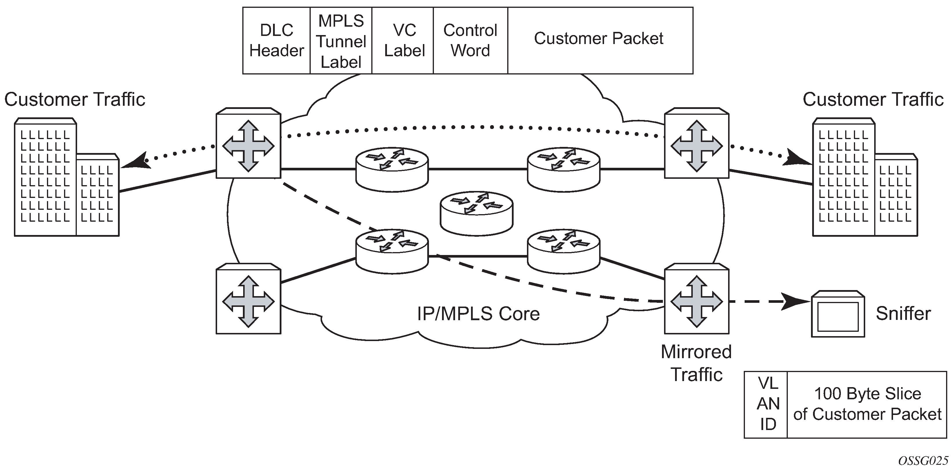
Nokia routers support service-based mirroring. While some Layer 3 switches and routers can mirror on a per-port basis within the device, Nokia routers can mirror on an n-to-1 unidirectional service basis and re-encapsulate the mirrored data for transport through the core network to another location, using either IP or MPLS tunneling as required (Service mirroring).
Original packets are forwarded while a copy is sent out the mirrored port to the mirroring (destination) port. Service mirroring allows an operator to see the actual traffic on a customer’s service with a sniffer sitting in a central location. In many cases, this reduces the need for a separate, costly overlay sniffer network.
The mirrored frame size that is to be transmitted to the mirror destination can be explicitly configured by using slicing features. This enables mirroring only the parts needed for analysis. For example, only the headers can be copied for analysis, protecting the integrity and security of customer data, or conversely, copying the full packet, including customer data.
Mirror implementation
Mirroring can be implemented on SAPs or ingress network interfaces. The Flexible Fast Path processing complexes preserve the original packet throughout the forwarding and mirroring process, making any necessary packet changes, such as adding encapsulation, on a separate copy.
Mirroring supports multiple types of destinations including local SAPs, remote tunnels, and FTP servers in PCAP format.
Nokia’s implementation of packet mirroring is based on the following assumptions:
Ingress and egress packets are mirrored as they appear on the wire. This is important for troubleshooting encapsulation and protocol issues.
When mirroring at ingress, the Flexible Fast Path network processor array (NPA) sends an exact copy of the original ingress packet to the mirror destination while normal forwarding proceeds on the original packet.
When mirroring is at egress, the system performs normal packet handling on the egress packet, encapsulating it for the destination interface. A copy of the forwarded packet is forwarded to the mirror destination. Because the mirror copy of the packet is created before egress queuing, the mirrored packet stream may include copies of packets that are discarded in egress queues, such as during congestion or rate limiting.
Remote destinations are reached by encapsulating the ingress or egress packet within an SDP, like the traffic for distributed VPN connectivity services. At the remote destination, the tunnel encapsulation is removed and the packet is forwarded out a local SAP.
Mirror components
Mirroring a packet consists of two components:
mirror destinations
This is where to send the mirrored packet. Various mirror destinations are available and each mirror destination consists of a service ID. Mirrored packets can be sent to a single mirror destination only.
mirror sources
Specify the packets to be mirrored. A mirror source can be configured through debug or service commands.
Mirror source
Mirror sources have the following properties:
When config>mirror>mirror-source and debug>mirror-source reference the same mirror source (for example, sap 1/1/1), config always takes precedence over debug, and config removes the debug configuration.
A mirror source can only be mirrored once. It is not possible to send a mirror source to two different mirror destinations.
Ports configured as host ports for satellite and ESA applications are not supported as mirror-source.
Internal ports such as ISA and ESA do not support config>mirror>mirror-source and there is only limited support for debug>mirror.
Types and sources
The following commands are supported for debug configuration:
ingress-label
ip-filter
ipv6-filter
isa-aa-group
mac-filter
port
sap
subscriber
The following commands are supported for config>mirror>mirror-source:
ip-filter
ipv6-filter
mac-filter
port
sap
subscriber
Subscriber mirroring applies only to the 7750 SR, 7450 ESS, 7750 SR-s, 7750 SR-e and 7750 SR-a platforms. Enhanced subscriber management associates subscriber hosts with queuing and filtering resources in a shared SAP environment. Mirroring used in subscriber aggregation networks for lawful intercept and debugging is required. Subscriber mirroring capability allows the match criteria to include a subscriber ID.
Subscriber mirroring can also be based on the IP family and host type. The IP family determines if only IPv4 or IPv6 addresses should be mirrored and the host type determines if only IPoE or PPP hosts should be mirrored from the subscriber. To use the IP family and host type, the SAP anti-spoof filter must be set to ip-mac. If subscriber mirroring is performed on the L2TP LAC and the IP family is configured as IPv6, no traffic is mirrored for the PPPoE session, even if the LAC subscriber is dual stack. For L2TP LAC, it is recommended that the IP family not be configured or be configured for IPv4 only.
Subscriber mirroring creates a mirror source with subscriber information as match criteria. Specific subscriber packets can be mirrored when using ESM with a shared SAP without prior knowledge of their IP or MAC addresses and without concern that they may change. The subscriber mirroring decision is more specific than a SAP. If a SAP (or port) is placed in a mirror and a subscriber host of which a mirror was configured is mirrored on that SAP, packets matching the subscriber host are mirrored to the subscriber mirror destination.
The mirroring configuration can be limited to specific forwarding classes used by the subscriber. When a forwarding class (FC) map is placed on the mirror, only packets that match the specified FCs are mirrored. A subscriber can be referenced in maximum two different mirror-destinations: one for ingress and one for egress.
Subscriber-based criteria in a mirror source remains in the mirror or LI source configuration even if the subscriber is deleted, removed, or logged off. When the subscriber returns (is configured, created, or logged in) the mirroring resumes. This also implies that a subscriber can be configured as a mirror or LI source before the actual subscriber exists on the node and before the subscriber ID is active (the mirroring starts when the subscriber is created or logs in and the subscriber ID becomes active).
Mirror source priority
An operator can configure multiple mirror source services, each asking for the same packets. For instance, using two different mirror source services for a filter and SAPs from the same port. A packet is only mirrored once and in such cases the system selects the highest priority mirror. The mirror source priority, from lowest to highest priority for access ports, is defined below:
-
port mirroring
-
SAP mirroring
-
subscriber mirroring
-
filter mirroring
As an example, when mirroring is enabled on a port for both filter and SAP, packets that matches filter entries rule are mirrored first to the mirror destination for the filter. The rest of the packets that do not match the filter are mirrored to the mirror destination specified for the SAP.
The mirror source priority, from lowest to highest priority for network ports, is defined below:
-
port mirroring
-
label mirroring
-
filter mirroring
Mirror destination
Mirror destinations have the following characteristics:
Mirror destinations can terminate on egress virtual ports which allows multiple mirror destinations to send to the same packet decode device, delimited by IEEE 802.1Q (referred to as Dot1q) tags. This is helpful when troubleshooting a multi-port issue within the network.
When multiple mirror destinations terminate on the same egress port, the individual dot1q tags can provide a DTE/DCE separation between the mirror sources.
Packets ingressing a port can have a mirror destination separate from packets egressing another or the same port (the ports can be on separate nodes).
Multiple mirror destinations are supported (local or remote) on a single chassis.
The operational state of a mirror destination depends on the state of all the outputs of the mirror. The mirror destination goes operationally down if all the outputs are down (for example, all mirror-dest>sap and mirror-dest>spoke-sdp objects are down, and all gateways configured under mirror-dest>encap do not have a known route by which they can be reached). The state of a mirror destination does not depend on inputs such as SDPs configured under mirror-dest>remote-source, debug>mirror-source entries, or configure>li>li-source entries. Some examples of outputs include mirror-dest>sap and mirror-dest>spoke-sdp.
configure>mirror-source and li>li-source can re-use the mirror-destination service that is currently in use by a debug>mirror-source. In this scenario, the system automatically cleans up the debug>mirror-source entries before it can be re-used. From Release 19.10.R1 onward, config and LI must reference different mirror destinations.
In classic CLI mode, mirror destination supports the following mirror-type values:
ether
ppp
ip-only
satop-e1
cesopsn
cesopsn-cas
In mixed and MD-CLI mode, only the following mirror-type values are supported: ether and ip-only.
To switch from classic to mixed or MD-CLI mode, all mirror types other than ether and ip-only must be manually removed first.
The following mirror destinations are supported:
- sap
- mirroring to a local SAP
- spoke-sdp
- mirroring to a remote location using a SDP. The remote location uses the remote source to terminate the spoke SDP
- remote-source
- used at the remote location that is terminating the spoke SDP mirroring tunnel
- pcap
- mirroring to an FTP server as a PCAP file
- encap
- mirroring to a remote location as an IP encapsulated packet
- endpoint
- tunneling redundancy support
General local and remote mirroring
Mirrored frames can be copied and sent to a specific local destination or service on the router (local mirroring) or copies can be encapsulated and sent to a different router (remote mirroring). This functionality allows network operators to centralize not only network analyzer (sniffer) resources, but also the technical staff who operate them.
The router allows multiple concurrent mirroring sessions so traffic from more than one ingress mirror source can be mirrored to the same or different egress mirror destinations.
Remote mirroring uses an SDP which acts as a logical way of directing traffic from one router to another through a unidirectional service tunnel. The SDP terminates at the far-end router which directs packets to the correct destination on that device.
The SDP configuration from the mirrored device to a far-end router requires a return path SDP from the far-end router back to the mirrored router. Each device must have an SDP defined for every remote router to which it wants to provide mirroring services. SDPs must be created first, before services can be configured.
Mirror destination type IP-only
The IP mirroring capability for the 7750 SR and 7950 XRS allows a mirror to be created with a parameter that specifies that only the IP packet is mirrored without the original POS/Ethernet DLC header. This results in the mirrored IP packet becoming media-agnostic on the mirror service egress.
This option is configurable on SAP mirrors for IES, VPRN and VPLS services, Ipipe services, and subscriber mirrors. It is not supported on VLL services such as Epipe, or on ports.
-
remote mirroring termination
With remote mirroring, the mirror destination configuration can allow IP packets to be mirrored from a source router. The packets are delivered to the destination in a spoke-terminated interface created in a VPRN service. IES interfaces are not supported. The interface can be configured with policy-based routing filters to allow sniffer selection based on incoming mirrored destination IP addresses. The interface cannot send traffic out as it is a destination-only feature. Packets arriving at the interface are routed based on the routing information within the VPRN. Policy-based routing should always be used unless only a sniffer is connected to the VPRN.
Figure 2. Remote mirroring termination 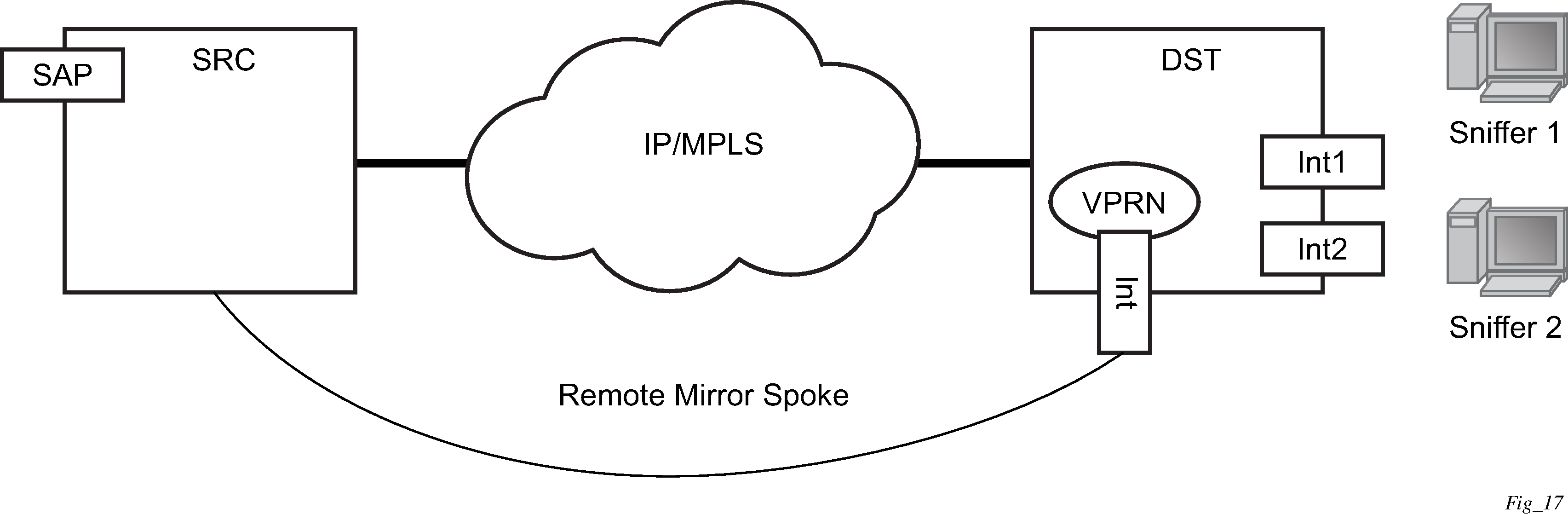
-
local mirroring termination
Local mirroring is like remote mirroring but the source and destination of the mirror exist in the same local IP mirroring node. The configuration must include the source address and destination MAC addresses for the packets going to the sniffer. The destination SAP must be Ethernet.
Mirror destination type PPP with port-ID insertion
Operators that use mirroring for statistics collection make use of VLANs or DLCIs for customer separation. Because PPP offers no such separation, the maximum number of PPP circuits may be identified (one per destination). This provides a proprietary mechanism to allow a single mirror to be used and only applies to the 7450 ESS and 7750 SR.
Port-ID-enabled PPP mirroring includes the port ID of the system in the mirrored packet. An operator using this flag in a PPP mirror can identify the end customer circuit by finding the system port ID (which can be made persistent) and correlating it to the port ID in the mirrored packet.
This mirroring does not change the priority of the mirror order (port, SAP, sub, filter). LI mirrors can use the port ID flag and their priority is also maintained.
Because the inclusion of the port ID flag is set on the mirror destination, all mirrored packets of all sources include the port ID. For remote mirroring, the mirror destination service at the source node must be configured with this flag.
The following restrictions apply to the port ID flag:
This flag can only be used with a PPP mirror destination.
This flag and a remote-source are mutually exclusive.
This flag cannot be enabled on an IP mirror type.
Layer 3 encapsulation
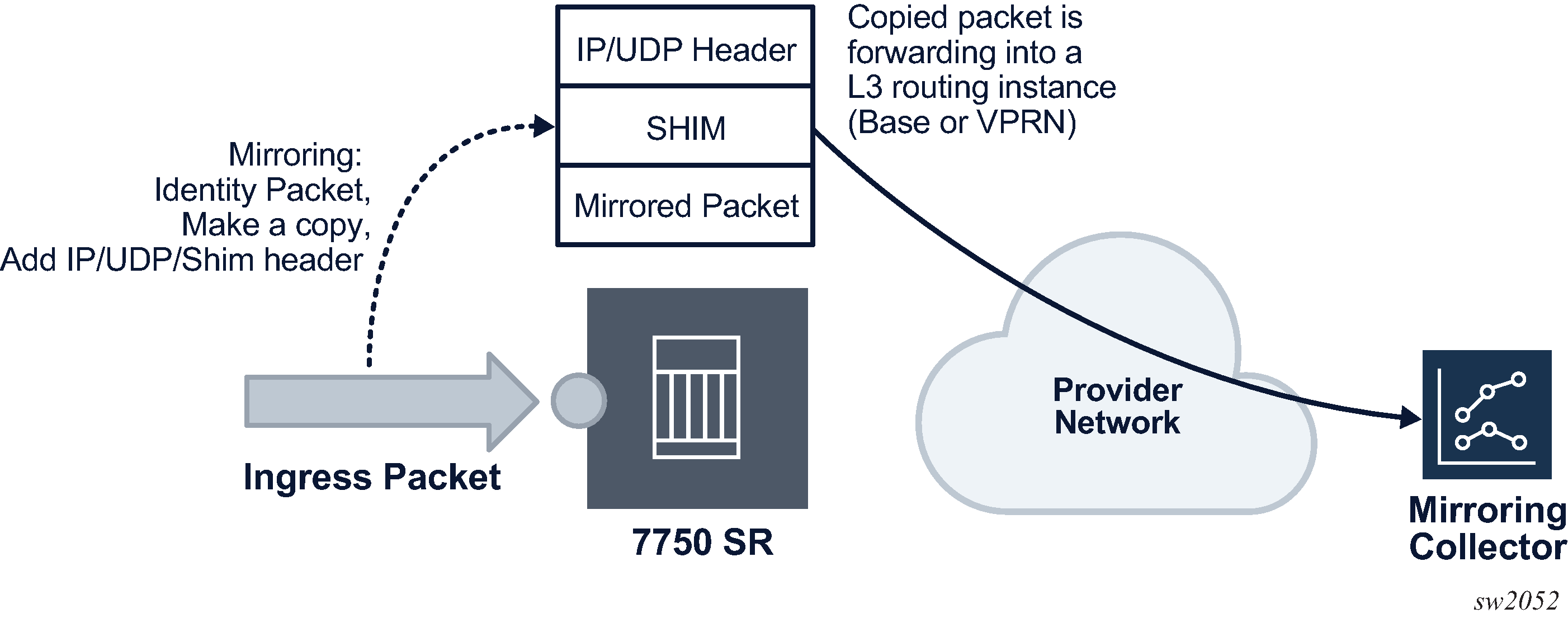
The routable encapsulation feature allows mirrored packets to be placed in a routable IP/UDP header and then forwarded in a routing context (either base or VPRN). An additional shim header is also added before the mirrored packet to provide additional context to the collector receiving the packets and contains the direction, mirror type, filter action, interface type, and interface value. This routable encapsulation is available using the layer-3-encap ip-udp-shim-sampled command and is supported for ingress and egress mirroring. It can be combined with mirror sampling, slicing, mirror-type ether, and ip-only. Routable mirror encapsulation shows the routable mirror encapsulation and Shim header format shows the shim header format.
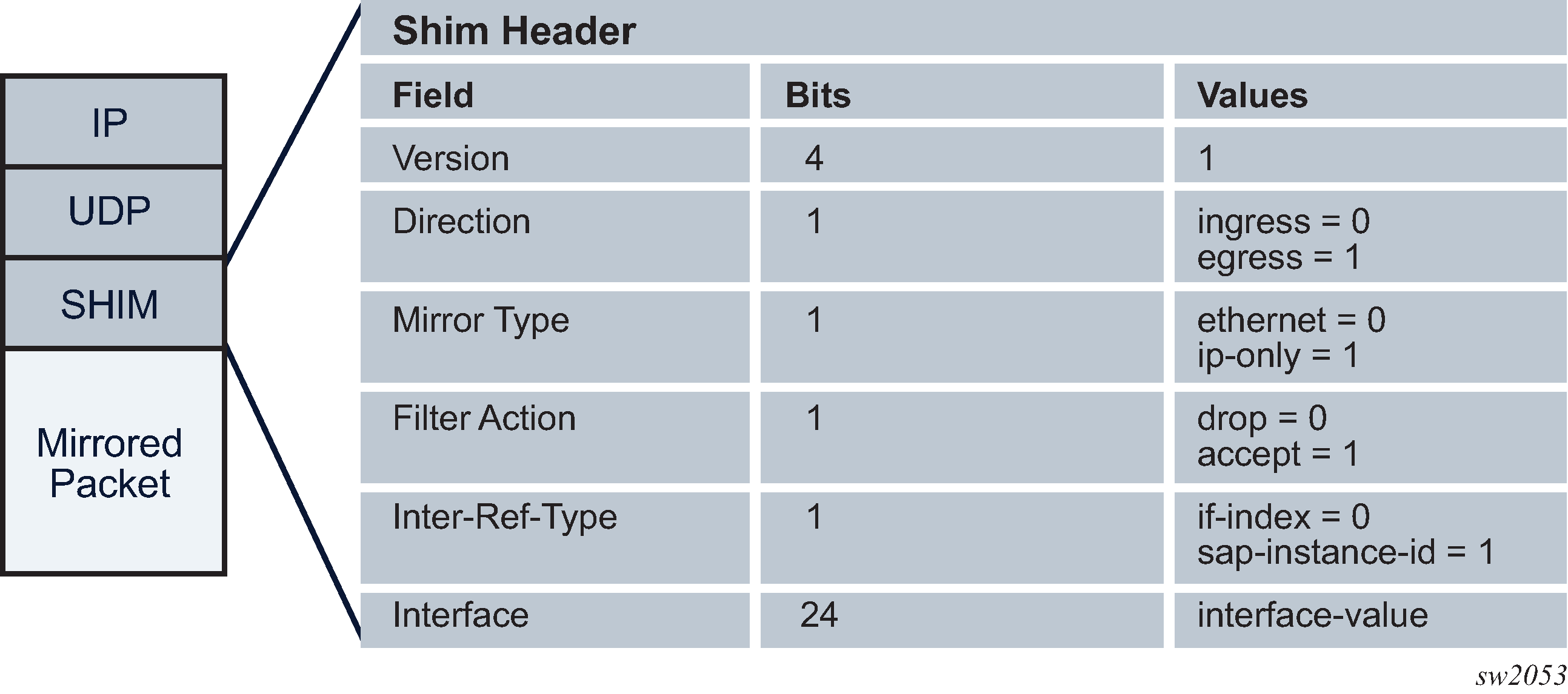
The encoding of the shim header is as follows:
Version (4 bits)
This describes the shim header version. The only supported version is 1.
Direction (1 bit)
This describes if the packet was mirrored ingress or egress.
Ingress = 0
Egress = 1
Mirror Type (1 bit)
This describes the mirror type.
Ethernet = 0
IP-Only = 1
Filter Action (1 bit)
This describes the result of the line card filter action as dropped or accepted. This can be further used by the collector for telemetry purposes.
Drop = 0
Accept = 1
Interface-Ref-Type (1 bit)
This indicates whether the interface represents an interface index or a SAP instance.
if-index = 0
sap-instance-id = 1
Interface (24 bits)
This can be either a sap-instance-id or the if-index value depending on the interface-ref-type value.
The if-index is used in the following mirror source cases:
For network interface, IES/VPRN SAP interface, or interface binding (spoke SDP IP interface), the interface if-index is used.
For MPLS transit and spoke/mesh-SDP in Layer 2 services, the if-index of the network interface the traffic is received from is used.
For R-VPLS IP packets to the router interface MAC as well as broadcast and multicast, R-VPLS interface if-index is used.
For ESM, the subscriber interface if-index is used.
The sap-instance-id is used for Layer 2 service SAPs and is an internal reference for the SAP string. The mapping table between the SAP instance ID and SAP strings can be obtained by using the SNMP table tMirrorSourceSapShimTable. The sap-instance-id found in the shim header can be correlated offline by the collector with tMirrorSourceSapShimTable to identify the SAP string and service the packet was mirrored from.
Filter action, interface-ref-type, and interface values are 0 in the case of egress mirroring.
The following restrictions apply to ip-udp-shim-sampled encapsulation:
FP2- and FP3-based cards are not supported as mirror source endpoints. Traffic from these endpoints is not mirrored if they are configured as a mirror source.
IP UDP shim sampled encapsulation is not applicable to PPP, SAToP, or CESoPSN mirror-dest types.
IP UDP shim encapsulation is only supported over IPv4 transport (it is not supported over IPv6 transport).
Forwarding of routable encapsulated packets from an R-VPLS interface is not supported. Routable encapsulated packets that arrive at the egress of an R-VPLS interface are discarded.
On the source node where LI mirroring occurs, the operator must configure the mirror destination to inject into the routing instance (that is, base or VPRN) in which the actual destination address is reachable without having to hop into a different instance using GRT leaking. In other words, the interface out of which the packet travels must exist in the routing instance that is configured in the mirror destination.
PCAP packet capture
Packet capture is a troubleshooting tool that uses both mirroring and debugging. A user’s CLI profile must have debug privileges to perform packet capture. To enable packet capture perform the following steps.
-
Set up the mirror destination (in this case, a PCAP). Specify the
file URL to which the packet captures are to be sent using the
mirror-dest command. The packet captures are packaged
into the libpcap file format.
The file URL requires the full path, including both username and password, and the filename. When configured, the system performs a syntax check, including an FTP connection test. The configured file URL is rejected if the syntax check fails.
- Specify the source for packet capture. Using either the debug
mirror-source or config mirror mirror-source
CLI commands, specify the source to be captured. All mirror sources are
supported, including IP-filter, subscriber, SAP, and ports.
The debug mirror-source service-id must match the mirror-dest service-id for the PCAP.
-
Begin the capture using the debug pcap
session-name
capture start CLI command. The following conditions
apply:
-
Previous captures with the same filename are overwritten. To avoid a file overwrite, create a new capture with a new filename. This can be accomplished by either renaming the file on the FTP server or by renaming the filename in the mirror destination.
-
This CLI command restarts the file transfer session with the remote FTP server.
-
If the remote FTP server is unreachable, the command prompt can pause while attempting to re-establish the remote FTP session. The total wait time can be up to 24 seconds (after four attempts of approximately six seconds each).
-
If the debug command pauses, verify the following items:
-
the connectivity to the server through the FTP port
-
the FTP user permissions on the FTP server
-
that the FTP server is functional
-
-
The file capture continues indefinitely until the user manually specifies for the packet capture to stop.
-
If the file capture fails to start, enter the show pcap session-name detail command to see the status of the capture. The detail prompt notifies the operator of the error, and it may require the operator to stop and re start the capture again.
-
-
End the capture. To stop the capture, enter the debug
pcap
session-name
capture stop CLI command. This command stops the file
transfer session and terminates the FTP session.
-
If the FTP server is unreachable, the command prompt rejects further input while it attempts to re-establish the remote FTP session. The total wait time can be up to 24 seconds (4 attempts of approximately 6 seconds each).
-
If the debug command pauses, check the following items:
-
the connectivity to the server through FTP port
-
the FTP user permissions on the FTP server
-
that the FTP server is functional
-
-
The mirrored packets are placed in a buffer in the CPM before they are transferred over FTP or TFTP. The buffer holds a maximum of 20 Mb. The FTP transfer is performed every 0.5 seconds. Each packet that is transferred successfully is flushed from the buffer. Therefore, to ensure all packets are captured successfully, the capture rate must not exceed 20 Mb in 0.5 seconds and the FTP transfer must not exceed 320 Mb/s of bandwidth (20 Mb per 0.5 seconds).
In the following show pcap output, the statistics, the session state, write failure, read failures, process time bailouts, and dropped packets are key elements for identifying whether the packet capture on the FTP server is reliable.
A:DUT> show pcap "2" detail
===============================================================================
Pcap Session "2" Information
===============================================================================
Application Type   : mirror-dest        Session State   : ready
Capture            : stop               Last Changed    : 02/06/2018 19:52:07
Capture File Url   : ftp://*:*@192.168.41.1/pcap2.pcap
Buffer Size        : 10 Bytes           File Size       : 200 Bytes
Write Failures     : 0                  Read Failures   : 0
Proc Time Bailouts : 0                  Last File Write : 02/06/2018 19:52:07
Dropped Packets    : 661 Packets
===============================================================================
Packet capture is a troubleshooting tool. Therefore, all CLI commands except for the FTP URL destination are located under debug. This allows the administrator to set up a CLI profile specifically for packet capture with debug privileges.
The packet capture uses FTP for file transfer and can be routed to the destination using the management port or through the IOM port. If the FTP server destination is routed through the management port, consider the maximum bandwidth available.
Mechanisms are built in to prevent mirroring or packet captures that result in loops or daisy-chains. However, it is possible to form a loop or daisy-chain if routing re routes or configuration changes. When a packet capture becomes looped or daisy-chained, the packet capture stops.
Mirrored traffic transport using MPLS-TP SDPs
Bidirectional MPLS-TP spoke SDPs with a configured pw-path-id can transport a mirrored service. Mirror services are not supported on static PWs with an MPLS-TP pw-path-id bound to an SDP that uses an RSVP-TE LSP.
Mirror services using MPLS-TP spoke SDPs can be configured using CLI in the context mirror-dest>remote-source. For both the CPM and IOM, this enables reuse of spokes for mirror services and other services such as pipes.
Control channel status signaling is supported with PW redundancy on spoke SDPs in a mirror context.
The following is an example of PW redundancy for a mirror service. In this case, MPLS-TP spoke SDPs are used.
Note that mirroring traffic is usually unidirectional, flowing from ‟source” nodes (B or C) to ‟destination” nodes (D or E). However, in case of MPLS-TP, the control channel status packets may flow in the reverse direction.
The following is an example of a mirror service configuration using MPLS-TP spoke SDPs:
Source node B
#--------------------------------------------------
    echo "Mirror Configuration"
#--------------------------------------------------
        mirror
            mirror-dest 300 create
                endpoint "X" create
                    revert-time 100
                exit
                endpoint "Y" create
                    revert-time 100
                exit
                remote-source
                    spoke-sdp 230:1300 endpoint "Y" icb create
                        ingress
                            vc-label 13301
                        exit
                        egress
                            vc-label 13301
                        exit
                        control-word
                        pw-path-id
                            agi 1:1
                            saii-type2 1:10.20.1.2:13301
                            taii-type2 1:10.20.1.3:13301
                        exit
                        control-channel-status
                            refresh-timer 10
                            no shutdown
                        exit
                        no shutdown
                    exit
                exit
                spoke-sdp 240:300 endpoint "X" create
                    ingress
                        vc-label 2401
                    exit
                    egress
                        vc-label 2401
                    exit
                    control-word
                    pw-path-id
                        agi 1:1
                        saii-type2 1:10.20.1.2:2401
                        taii-type2 1:10.20.1.4:2401
                    exit
                    control-channel-status
                        refresh-timer 10
                        no shutdown
                    exit
                    no shutdown
                exit
                spoke-sdp 250:300 endpoint "X" create
                    ingress
                        vc-label 6501
                    exit
                    egress
                        vc-label 6501
                    exit
                    control-word
                    pw-path-id
                        agi 1:1
                        saii-type2 1:10.20.1.2:6501
                        taii-type2 1:10.20.1.5:6501
                    exit
                    control-channel-status
                        refresh-timer 10
                        no shutdown
                    exit
                    no shutdown
                exit
                spoke-sdp 230:300 endpoint "X" icb create
                    ingress
                        vc-label 12301
                    exit
                    egress
                        vc-label 12301
                    exit
                    control-word
                    pw-path-id
                        agi 1:1
                        saii-type2 1:10.20.1.2:12301
                        taii-type2 1:10.20.1.3:12301
                    exit
                    control-channel-status
                        refresh-timer 10
                        no shutdown
                    exit
                    no shutdown
                exit
                no shutdown
            exit
        exit
exit all
Destination node C
#--------------------------------------------------
echo "Mirror Configuration"
#--------------------------------------------------
    mirror
        mirror-dest 300 create
            endpoint "X" create
                revert-time 100
            exit
            endpoint "Y" create
                revert-time 100
            exit
            remote-source
                spoke-sdp 230:1300 endpoint "Y" icb create
                    ingress
                        vc-label 13301
                    exit
                    egress
                        vc-label 13301
                    exit
                    control-word
                    pw-path-id
                        agi 1:1
                        saii-type2 1:10.20.1.3:13301
                        taii-type2 1:10.20.1.2:13301
                    exit
                    control-channel-status
                        refresh-timer 10
                        no shutdown
                    exit
                    no shutdown
                exit
            exit
            spoke-sdp 340:300 endpoint "X" create
                ingress
                    vc-label 6501
                exit
                egress
                    vc-label 6501
                exit
                control-word
                pw-path-id
                    agi 1:1
                    saii-type2 1:10.20.1.3:6501
                    taii-type2 1:10.20.1.4:6501
                exit
                control-channel-status
                    refresh-timer 10
                    no shutdown
                exit
                no shutdown
            exit
            spoke-sdp 350:300 endpoint "X" create
                ingress
                    vc-label 2401
                exit
                egress
                    vc-label 2401
                exit
                control-word
                pw-path-id
                    agi 1:1
                    saii-type2 1:10.20.1.3:2401
                    taii-type2 1:10.20.1.5:2401
                exit
                control-channel-status
                    refresh-timer 10
                    no shutdown
                exit
                no shutdown
            exit
            spoke-sdp 230:300 endpoint "X" icb create
                ingress
                    vc-label 12301
                exit
                egress
                    vc-label 12301
                exit
                control-word
                pw-path-id
                    agi 1:1
                    saii-type2 1:10.20.1.3:12301
                    taii-type2 1:10.20.1.2:12301
                exit
                control-channel-status
                    refresh-timer 10
                    no shutdown
                exit
                no shutdown
            exit
            no shutdown
        exit
    exit
Source node D
#--------------------------------------------------
echo "Mirror Configuration”
#--------------------------------------------------
    mirror
        mirror-dest 300 create
            endpoint "X" create
                revert-time 100
            exit
            endpoint "Y" create
                revert-time 100
            exit
            remote-source
                spoke-sdp 240:300 endpoint "Y" create
                    ingress
                        vc-label 2401
                    exit
                    egress
                        vc-label 2401
                    exit
                    control-word
                    pw-path-id
                        agi 1:1
                        saii-type2 1:10.20.1.4:2401
                        taii-type2 1:10.20.1.2:2401
                    exit
                    control-channel-status
                        refresh-timer 10
                        no shutdown
                    exit
                    no shutdown
                exit
                spoke-sdp 340:300 endpoint "Y" create
                    ingress
                        vc-label 6501
                    exit
                    egress
                        vc-label 6501
                    exit
                    control-word
                    pw-path-id
                        agi 1:1
                        saii-type2 1:10.20.1.4:6501
                        taii-type2 1:10.20.1.3:6501
                    exit
                    control-channel-status
                        refresh-timer 10
                        no shutdown
                    exit
                    no shutdown
                exit
                spoke-sdp 450:1300 endpoint "Y" icb create
                    ingress
                        vc-label 13301
                    exit
                    egress
                        vc-label 13301
                    exit
                    control-word
                    pw-path-id
                        agi 1:1
                        saii-type2 1:10.20.1.4:13301
                        taii-type2 1:10.20.1.5:13301
                    exit
                    control-channel-status
                        refresh-timer 10
                        no shutdown
                    exit
                    no shutdown
                exit
            exit
            sap lag-10:300.1 endpoint "X" create
            exit
            spoke-sdp 450:300 endpoint "X" icb create
                ingress
                    vc-label 12301
                exit
                egress
                    vc-label 12301
                exit
                control-word
                pw-path-id
                    agi 1:1
                    saii-type2 1:10.20.1.4:12301
                    taii-type2 1:10.20.1.5:12301
                exit
                control-channel-status
                    refresh-timer 10
                    no shutdown
                exit
                no shutdown
            exit
            no shutdown
        exit
    exit
Destination node E
#--------------------------------------------------
echo "Mirror Configuration"
#--------------------------------------------------
    mirror
        mirror-dest 300 create
            endpoint "X" create
                revert-time 100
            exit
            endpoint "Y" create
                revert-time 100
            exit
            remote-source
                spoke-sdp 250:300 endpoint "Y" create
                    ingress
                        vc-label 6501
                    exit
                    egress
                        vc-label 6501
                    exit
                    control-word
                    pw-path-id
                        agi 1:1
                        saii-type2 1:10.20.1.5:6501
                        taii-type2 1:10.20.1.2:6501
                    exit
                    control-channel-status
                        refresh-timer 10
                        no shutdown
                    exit
                    no shutdown
                exit
                spoke-sdp 350:300 endpoint "Y" create
                    ingress
                        vc-label 2401
                    exit
                    egress
                        vc-label 2401
                    exit
                    control-word
                    pw-path-id
                        agi 1:1
                        saii-type2 1:10.20.1.5:2401
                        taii-type2 1:10.20.1.3:2401
                    exit
                    control-channel-status
                        refresh-timer 10
                        no shutdown
                    exit
                    no shutdown
                exit
                spoke-sdp 450:1300 endpoint "Y" icb create
                    ingress
                        vc-label 13301
                    exit
                    egress
                        vc-label 13301
                    exit
                    control-word
                    pw-path-id
                        agi 1:1
                        saii-type2 1:10.20.1.5:13301
                        taii-type2 1:10.20.1.4:13301
                    exit
                    control-channel-status
                        refresh-timer 10
                        no shutdown
                    exit
                    no shutdown
                exit
            exit
            sap lag-10:300.1 endpoint "X" create
            exit
            spoke-sdp 450:300 endpoint "X" icb create
                ingress
                    vc-label 12301
                exit
                egress
                    vc-label 12301
                exit
                control-word
                pw-path-id
                    agi 1:1
                    saii-type2 1:10.20.1.5:12301
                    taii-type2 1:10.20.1.4:12301
                exit
                control-channel-status
                    refresh-timer 10
                    no shutdown
                exit
                no shutdown
            exit
            no shutdown
        exit
    exit
Slicing and sampling
Slicing and sampling are available to all mirror destinations:
-
slicing
Slicing copies a specified packet size of each frame. This is useful to monitor network usage without having to copy the actual data. Slicing enables mirroring larger frames than the destination packet decode equipment can handle. It also allows conservation of mirroring resources by limiting the size of the stream of packet through the router and the core network.
When a mirror slice size is defined, a threshold that truncates a mirrored frame to a specific size is created. For example, if a value of 256 bytes is defined, up to the first 256 bytes of the frame are transmitted to the mirror destination. The original frame is not affected by the truncation. Mirrored frames, most likely, become larger as encapsulations are added when packets are transmitted through the network core or out the mirror destination SAP to the packet or protocol decode equipment. Slice size is not supported by CEM encap-types or IP mirroring.
The transmission of a sliced or non-sliced frame is also dependent on the mirror destination SDP path MTU and the mirror destination SAP physical MTU. Packets that require a larger MTU than the mirroring destination supports are discarded if the defined slice size does not truncate the packet to an acceptable size.
-
sampling
Mirror sampling rate defines a packet sampling rate for a mirror service. The sampling rate is applicable to all endpoints in the mirror source ingress and egress and supported on FP4 and FP5-based cards.
This capability can be useful for analytics purposes such as DDoS telemetry to provide a subset of traffic while still maintaining statistical accuracy using packet sampling.
Packet sampling can be configured concurrently with mirror slicing to further limit the amount of traffic sent to the collector.
For endpoints in the mirror source on FP2- and FP3-based cards, all the packets are mirrored without sampling.
Global sampling rate
SR OS supports three types of sampling rates:
-
High-rate sampling
High-rate sampling allows the sampling of 1 packet out of every 2 to 255 packets. Use the following command to configure high-rate sampling.
configure mirror global-sampling-rateOptionally, each mirror destination service can adopt the global sampling rate, allowing one single high-rate sampling rate for the entire system, by using the following command.
configure mirror mirror-dest use-global-sampling-rate -
Low-rate sampling
Low-rate sampling allows the sampling of 1 packet out of every 256 to 10,000 packets. Unlike high-rate sampling, each mirror destination can use a different low-sampling rate. Use the following command to configure low-rate sampling for each destination.
configure mirror mirror-dest sampling-rate -
No sampling
When neither the use-global-sampling-rate or sampling-rate commands under the mirror destination, the system mirrors all packets to the destination.
Each mirror destination can use a different low-sampling rate. However, if the high-sampling rate is configured, using the global-sampling-rate command, all mirror destinations share the same high-sampling rate.
When both the low-rate and high-rate are configured under the same mirror destination, the low rate takes precedence. The system automatically samples using the low rate specified and ignores the global high rate.
Mirroring performance
Replication of mirrored packets can, typically, affect performance and should be used carefully. Nokia routers minimize the impact of mirroring on performance by taking advantage of its distributed Flexible Fast Path technology. Flexible Fast Path forwarding allows efficient mirror service scaling and, at the same time, allows a large amount of data to be mirrored with minimal performance impact. When a mirror destination is configured, the packet slice option can truncate mirrored packets to the destination, which minimizes replication and tunneling overhead.
Lawful Intercept
Lawful Intercept (LI) describes a process to intercept telecommunications by which law enforcement authorities can unobtrusively monitor voice and data communications to combat crime and terrorism with higher security standards of lawful intercept capabilities in accordance with local law and after following due process and receiving authorization from competent authorities. The interception capabilities are sought by various telecommunications providers.
As lawful interception is subject to national regulation, requirements vary from one country to another. Nokia’s implementation satisfies most national standard’s requirements. LI capability is configurable for all Nokia service types.
LI mirroring is configured by an operator that has LI permission. LI mirroring is hidden from anyone who does not have the right permission.
In Release 19.10.R1 and higher config and LI must use different mirror destinations.
LI activation through RADIUS
In addition to CLI and SNMP control, RADIUS messages also activate LI sessions for subscriber-host targets. Activation through RADIUS is equivalent to adding or removing a set of subscriber-host entries in an LI source.
The activation of an LI session via RADIUS applies to the 7450 ESS and 7750 SR and can occur in one of two ways:
when the RADIUS Access-Accept message is received by the 7450 ESS or 7750 SR. The target (either a host or a set of hosts) is implicit. The target acts as the same host (or set of hosts) that is within the scope of the Access-Accept and interception occurs for this entire set of hosts (or a single host).
through RADIUS CoA messages. The target (set of hosts) is identified through one of the following methods:
Acct-Session-Id (which can represent a single host or a collection of hosts)
a sap-id;ip-addr carried in the NAS-Port-Id (attr 87) and the Framed-Ip-Address (attr 8).” for IPv4 hosts
a sap-id;IPv6_addr carried in the NAS-Port-ID (attr 87) and one of Alc-Ipv6-Address, Framed-Ipv6-Prefix, or Delegated-Ipv6-Prefix for IPv6 hosts
Alc-Subsc-ID-Str
The following set of VSAs is used to activate LI sessions via RADIUS:
Alc-LI-Action – ON/OFF/NONE
Alc-LI-Destination - <string> and has two options:
the mirror destination service ID
at real time, specify the IP destination, the UDP port, and the router instance of the LI mediation device
The format for the VSA is ip-address [:port] [router instance]. The IP address must be of type IPv4 and is the only mandatory parameter.
Alc-LI-Direction – INGRESS/EGRESS
Alc-LI-FC – be/l1/l2/af/ef
(optional) Alc-LI-Use-Outside-IP
Use this VSA when the subscriber is an L2-aware NAT subscriber and uses the outside IP address instead of the private IP address for packet mirroring. See L2-Aware NAT for more details.
The Alc-LI-FC VSA can be present several times if more than one forwarding class (FC) is subject to LI.
The VSAs Alc-LI-Direction and Alc-LI-FC are optional. If either is not included, both directions (ingress and egress) as well as all FCs are mirrored.
The Alc-LI-Destination VSA can be used in one of the following ways:
A mirror destination must first be provisioned on SR. To use the mirror destination, the VSA specifies the mirror destination service ID in the Access-Accept message or a CoA.
The VSA specifies the IP address of the mirror destination through the Access-Accept message or a CoA. The reserved range of service IDs and the mirror destination template must be configured first. This VSA provisions the mirror destination using a combination of parameters from the LI template and RADIUS VSAs. The following should be considered when using this VSA:
Only Layer 3 encapsulation is supported as the mirror destination.
The VSA has the format ipv4-address [:port] [router {Base | svc-id}]. The VSA must include the LI destination IPv4 address, while the port and the routing instance are optional. If the destination port and routing instance are not specified in the VSA, the configuration from the LI mirror destination template is used.
With the LI mirror destination reservation, a list of service IDs is reserved for configuring the mirror destination via RADIUS. The LI mirror destination is shared with the mirror destination used for debugging purposes. Therefore, it is suggested to reserve enough for LI purposes, and leave enough for debugging and configuration. The VSA triggers the creation of a mirror destination automatically and uses one of the service IDs in the reservation range. An LI source that matches the IP source, IP destination, UDP destination, UDP source, and direction bit, reuses the same LI mirror destination service ID. The LI mirror destination reservation range can be expanded or reduced in real time. The range can be changed completely when there are no LI sources referenced in the mirror reservation range.
The LI mirror destination template specifies the parameters for the Layer 3 encapsulation. It is mandatory to provision the IP source, IP destination, UDP source, and UDP destination parameters.
It is possible to configure up to eight LI mirror destination templates. The mirror destination template can be switched in real time, if, for example, a parameter such as the source IP address is to be updated.
The system can block RADIUS from generating the mirror destination by removing a template reference under the config>li>radius context.
VSAs in the Access-Accept messages also activate LI for a newly-created host. In this case, the LI activation is not addressed by the Acct-Session-Id, as this is not yet known during session authorization.
Different attributes can be used in a CoA to identify one or more subscriber hosts. Typically, only a single attribute or set of attributes is used to target a host or several: NAS-Port-Id + IP, Acct-Session-Id, or Alc-Subsc-ID-Str. In the case where ‟NAS-Port-Id + IP” is used in a Wholesale or Retail model, the Alc-Retail-Serv-Id VSA must be included in the CoA.
The ability to delete all li-source entries from a mirror service is also available via RADIUS. This function may be useful when an LI mediation device loses synchronization with the SR OS state and needs to reset a mirror service to a known state with no LI sessions. This clear function is performed by sending the following attributes in a RADIUS CoA. If the CoA does not contain exactly the following three VSAs (each with a valid value matching the configuration on SR OS), the CoA is silently dropped without a NAK:
Alc-LI-Action
Alc-LI-Action = ‛clear-dest-service’
Alc-LI-Destination
The destination can specify the service ID of the mirror destination or it can pass the VSA in the mirror destination IP, where the mirror destination IP was automatically created by RADIUS.
Alc-LI-Destination = service-id, if a mirror destination service ID was used for LI
Alc-LI-Destination = ip-address [:port] [router instance]. The system deletes RADIUS auto-generated mirror destinations based on three parameters: the IP destination, the UDP destination port, and the router instance. These parameters can be passed in from the Alc-LI-Destination VSA. If the VSA provides only some of the parameters, for example, only the destination IP, the parameters from the mirror destination template is used (from config>li>mirror-dest-template). The three parameters determine the mirror service ID to delete and any combination of the IP source, UDP source port, and direction bit can be deleted. It is possible that a template change can prevent the VSA from deleting the mirror destination service. To manually delete a mirror destination, a CLI command is provided under clear li radius mirror-dest svc-id. To determine the service ID to delete, a manual login is required.
Alc-Authentication-Policy-Name
This VSA is only required in a specific configuration. The VSA is not required when a RADIUS server policy is configured under configure subscriber-mgmt authentication-policy and the RADIUS server policy servers are used as CoA servers.
This VSA is required in the configuration where the servers configured inside the authentication policy are used as CoA servers, with the following:
a list of servers is configured under config>subscr-mgmt>auth-plcy>radius-auth-server
accept-authorization-change is enabled under config>subscr-mgmt>auth-plcy
the authentication policy does not reference the RADIUS server policy
When the above conditions are met, the Alc-Authentication-Policy-Name VSA is required and must reference the authentication policy that contains the IP address of the LI CoA client.
The LI-related VSAs cannot be combined in one CoA message with other action-related VSAs (force renew, change of SLA profile, and so on). The only exception to this rule is for the CoA used to create a new subscriber host. In this case, LI-related VSAs can be included, along with other VSAs.
If LI is activated through CLI or SNMP, the activation through RADIUS takes precedence. The precedence in this context means that RADIUS activation of LI fully overrides whatever was configured at CLI or SNMP level for this host. If the RADIUS LI is de-activated, the CLI or SNMP configuration becomes active again.
The LI-related VSAs are not shown in debug messages. The show li li-source command shows all sub-hosts for which LI was activated using RADIUS VSAs. This command is only accessible to CLI users with LI privileges.
Routable Lawful Intercept encapsulation
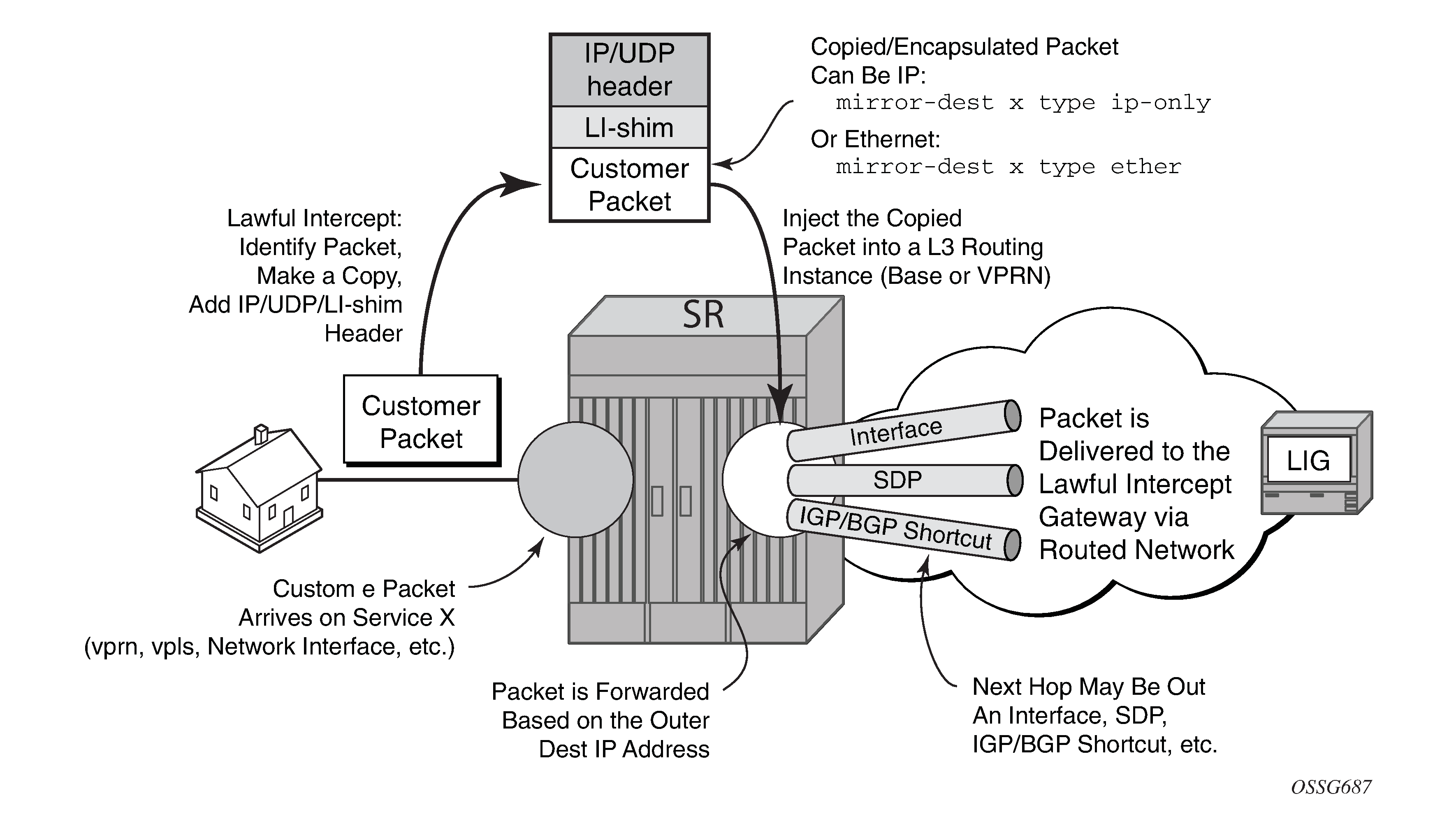
The Routable LI encapsulation feature allows LI mirrored packets to be placed into a routable (for example, IP/UDP) header and then forwarded in a routing context (base or VPRN). An LI-shim inserted before the customer packet allows correlation of packets to LI sessions at the downstream LI Mediation device (LIG).
Some of the supported attributes and scenarios for the routable LI encapsulation feature include the following:
The part of the customer packet that is copied and placed into the routable encapsulation can be either the IP packet (with none of the original Layer2 encap) or an Ethernet packet by selecting either ip-only or ether as the mirror-dest type.
The ability to inject into the Base routing instance (for forwarding out network interfaces or IES SAPs for example) or a VPRN service.
The ability to forward the encapsulated packets out VPRN SDPs, IGP/BGP shortcuts and SDP spoke interfaces.
Options to use ip, udp, li-shim or ip, gre routable encapsulation (applies to the 7450 ESS and 7750 SR).
An optional direction bit in the li-shim; if the use of the direction bit is configured, then a bit from the intercept-id (configure under mirror-dest) is ‟stolen”. Only a 29b intercept-id is allowed for li-source entries if the mirror destination is configured to use a direction bit.
Figure 8. LI-shim version 01 with a direction bit 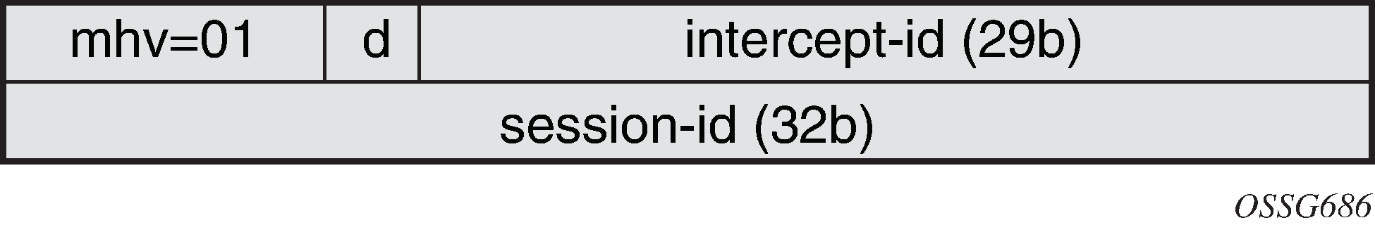
The encoding of the direction (d) bit is as follows:
0 = ingress
1 = egress
For NAT based LI, ingress means the traffic arriving at the node from the subscriber host (applies to the 7450 ESS and 7750 SR).
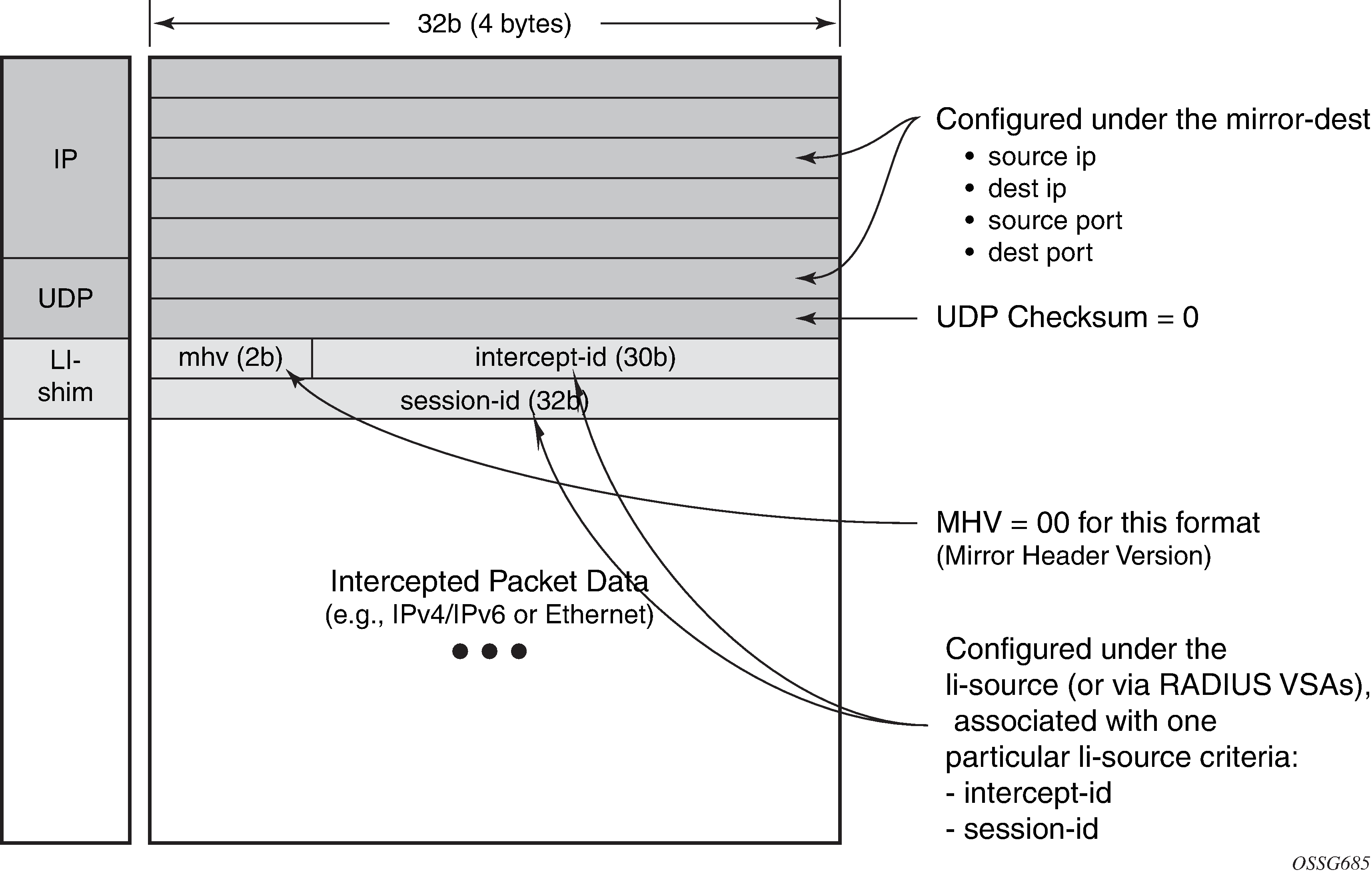
User configurable intercept-id and session-id per li-source entry that is placed into the li-shim (a total max of 62 configurable bits).
Configuration via CLI/SNMP or RADIUS (applies to the 7450 ESS and 7750 SR). For RADIUS configuration the following VSAs are used:
Alc-LI-Action, Alc-LI-Direction, Alc-LI-Destination, Alc-LI-FC (See LI activation through RADIUS).
Alc-LI-Intercept-Id specifies the intercept-id to place in the LI shim. Only applicable if the mirror-dest (as specified by the Alc-LI-Destination) is configured with routable encap that contains the LI-Shim. A value of 0 is used if this VSA is not present.
Alc-LI-Session-Id specifies the session-id to place in the LI-Shim. Only applicable if the mirror-dest (as specified by the Alc-LI-Destination) is configured with routable encap that contains the LI shim. A value of 0 is used if this VSA is not present.
A LI session configured via RADIUS takes precedence over a session configured via CLI, but the CLI mirror is re-instated if the RADIUS mirror request is later removed (applies to the 7450 ESS and 7750 SR)
ip, udp, and li-shim encap is available for ether and LI shim mirror-dest types.
- ip | udp | li-shim encap is available for all li-source entry types (sap, filter, subscriber and nat).Note: For NAT based Lawful Intercept, routable LI encap is available, as well as the MAC or Layer 2-based encapsulation for NAT LI as configured under config>li>li-source>nat>ethernet-encap (applies to the 7450 ESS and 7750 SR)
Fragmentation of the resulting mirror packet is supported. Note that fragmentation is supported for NAT LI with the routable encapsulation, but fragmentation is not supported for NAT LI with Ethernet encapsulation (applies to the 7450 ESS and 7750 SR).
The following restrictions apply to the routable LI encapsulation feature:
Only applicable to Lawful Intercept and is not available for debug or MS-ISA based Application Assurance mirrors. MS-ISA based Application Assurance is applicable to the 7450 ESS and 7750 SR.
Not applicable to PPP, SAToP, or CESoPSN mirror-dest types.
IPv4 transport only (the routable encapsulation cannot be IPv6).
On the mirror source node, forwarding of routable encapsulated LI packets out of an R-VPLS interface is not supported. A mirror destination configured with routable encapsulation can be bound to a routing instance that also has an R-VPLS bound to it, but the operator must ensure that the destination of the LI packets is not reachable via any R-VPLS interfaces. Any routable encapsulated LI packets that arrive at the egress of an R-VPLS interface are discarded. Parallel use of routable LI encapsulation and R-VPLS in the same routing instance is supported if the mirrored packets do not egress out of the R-VPLS interface.
ip | gre encap is supported for the ip-only mirror destination type only, and only for subscriber li-source entries (CLI, SNMP, or RADIUS based). Subscriber management is not supported on the 7950 XRS.
The contents of the GRE header are all zeros (all optional bits zero, no optional headers/fields like checksum, offset, key, seq, and so on) except for the Protocol field which contains 0x0800 for IPv4 packets or 0x86DD for IPv6 packets. The far-end receiver of the intercepted packets must be configured to expect no GRE options (that is, no key, no checksum, and so on).
On the source node where LI mirroring occurs, the operator must configure the mirror-dest to inject into the routing instance (that is, base or VPRN) in which the actual destination address is reachable without having to hop into a different instance using GRT leaking. In other words, the interface out, which the packet travels, must exist in the routing instance that is configured in the mirror-dest.
For example, if the LIG is at 110.120.130.140 and is in the base instance, but VPRN-1 has a default route to the GRT (for example, 0.0.0.0->GRT) then the operator must configure the mirror destination to inject into the base (even though theoretically address 110.120.130.140 is reachable from VPRN-1). If the operator attempts to configure the mirror destination to inject into VPRN-1, and VPRN-1 itself does not have reachability to 110.120.130.140 out an interface that is part of the VPRN, then the mirror destination is operationally down.
Care must be taken in the configuration of LI mirrors and the destination IP address for the routable LI encapsulation. Incorrect selection of the destination IP could send packets to unintended destinations (for example, configuring the encapsulation with a subscriber's IP address), and combinations of mirrors and routable encapsulation can create loops in the network.
Lawful Intercept and NAT
Carrier grade NAT
LI for NAT is supported to mirror configured subscriber’s traffic to a mirror destination. When active, packets are mirrored from the perspective of the NAT outside interface (after NAT translations have occurred). All traffic for the specified subscriber, including traffic associated with static port-forwards, is mirrored. This feature is supported for 7450 ESS and 7750 SR only.
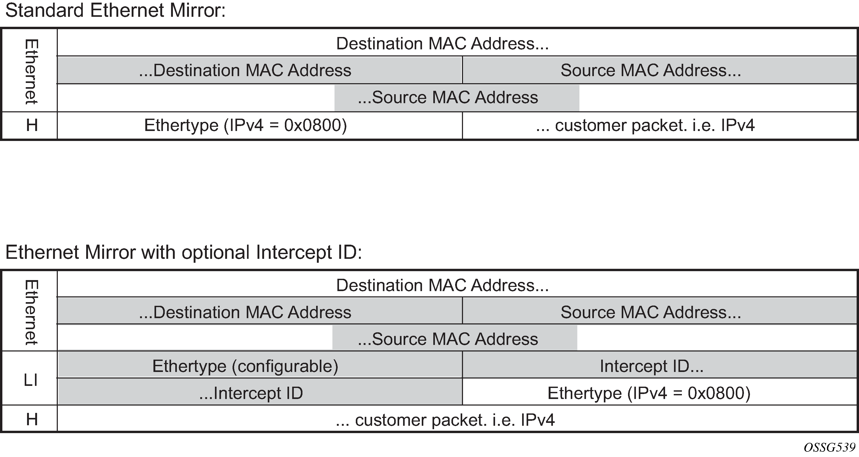
A simplified Ethernet encapsulation (with an optional Intercept ID) is used for all NAT traffic. When mirroring NAT traffic, the mirror destination must be of type ether. The customer packet from the (outside) IP header onwards (including the IP header) is mirrored. The operator has the configuration option of embedding the intercept ID into the LI packet using an explicit intercept-id command. Both packet formats are described below:
The contents of the highlighted fields are configurable using the following CLI:
li
    li-source service-id
         nat
             classic-lsn-sub router name ip address
                 intercept-id id
             dslite-lsn-sub router name b4 ipv6-address
                 intercept-id id
             l2-aware-sub sub-ident
                 intercept-id id
The default Ethernet-header is to use etype 0x600 and system MAC address for both the source and destination addresses. The configurable Ethertype and Intercept ID is only added when an intercept ID is present for the subscriber in the NAT configuration.
L2-Aware NAT
When Layer 3 encapsulation is configured as the mirror destination for an L2-Aware NAT subscriber, the mirror destination must be of type ip-only and the encapsulation must be of type ip-udp-shim. For L2-Aware NAT, it is possible to assign the same inside IPv4 private IP address to all subscribers. It is preferable to intercept the L2-Aware NAT subscriber using the outside IP address instead. This can be accomplished from both RADIUS and CLI as described in the following table.
| Lawful Intercept to use host inside IP address | Lawful Intercept to use host outside IP address | |
|---|---|---|
CLI access |
The command config>li>use-outside-ip-address does not apply to CLI configured LI targets. |
Configure the subscriber ID under config>li>li-source>nat>l2-aware-sub. The command config>li>use-outside-ip-address does not apply to CLI configured LI targets. |
RADIUS access |
|
|
When the RADIUS VSA Alc-LI-Use-Outside-IP is used, the configuration config>li>use-outside-ip-address is ignored.
Alc-Use-Outside-IP is only supported when the mirror destination service is configured with Layer 3 encapsulation.
L2-Aware subscribers do not support the LI RADIUS VSAs Alc-LI-FC and Alc-LI-Direction. When an L2-Aware subscriber is subjected to LI via CLI or RADIUS, dual stack traffic is mirrored.
Lawful Intercept management interfaces
LI can be managed using classic management interfaces (for example, classic CLI or SNMP) or model-driven management interfaces (MD-CLI or NETCONF). Management of LI is similar across all interfaces.
See ‟Classic and Model-Driven Management Interfaces” in the 7450 ESS, 7750 SR, 7950 XRS, and VSR System Management Guide for more information about management interfaces and setting the configuration mode.
LI management using the classic CLI engine
With the advent of support for both classic and mixed configuration modes for LI management, the classic engine supports the following additional features in classic configuration mode.
Classic CLI mode features for LI management are as follows:
LI filter names, as well as filter IDs, under li-filter-associations, including ip-filter-name, ipv6-filter-name, and mac-filter-name
Operators can choose between IDs and names (mutually exclusive).
IDs must be hard references and can only refer to filters (IP, IPv6, MAC) that already exist.
Names can be loose references and can refer to filters (IP, IPv6, MAC) that do not exist.
LI filter names, as well as filter IDs, under li-filter-block-reservation, including ip-filter-name, ipv6-filter-name, and mac-filter-name
Operators can choose between IDs and names (mutually exclusive).
IDs must be hard references and can only refer to filters (IP, IPv6, MAC) that already exist.
Names can be loose references and can refer to filters (IP, IPv6, MAC) that do not exist.
router-name in mirror destination template
Operators can choose between IDs and names (mutually exclusive).
IDs must be hard references and can only refer to router IDs (VPRNs) that already exists.
Names can be loose references and can refer to router IDs (VPRNs) that do not exist.
router-name in NAT li-source
Operators can choose between IDs and names (mutually exclusive).
IDs must be hard references and can only refer to router IDs (VPRNs) that already exists.
Names can be loose references and can refer to router IDs (VPRNs) that do not exist.
Classic CLI engine properties for classic and mixed configuration mode lists the classic CLI engine properties for classic and mixed configuration mode.
| Config CLI tree | Classic mode | Mixed mode |
|---|---|---|
li>li-filter-lock-state |
|
See Configurable filter lock for Lawful Intercept for more information |
li>li-source |
ID with name |
ID with name |
li>li-source>nat>classic-lsn-sub>router li>li-source>nat>dslite-lsn-sub>router li>li-source>nat>nat64-lsn-sub>router |
ID or name (router and router-name are mutually exclusive) |
ID or name (router and router-name are mutually exclusive) |
li>mirror-dest-template>router |
ID or name (router and router-name are mutually exclusive) |
ID or name (router and router-name are mutually exclusive) |
li>li-filter-associations>li-ip-filter>ip-filter li>li-filter-associations>li-ipv6-filter>ipv6-filter li>li-filter-associations>li-mac-filter>mac-filter |
ID or name (ID and name are mutually exclusive) |
name only |
li>li-filter-block-reservation>li-reserved-block>ip-filter li>li-filter-block-reservation>li-reserved-block>ipv6-filter li>li-filter-block-reservation>li-reserved-block>mac-filter |
ID or name (ID and name are mutually exclusive) |
name only |
Reference types for classic and mixed configuration mode lists the reference types for classic and mixed configuration mode.
| Config CLI tree | Classic mode | Mixed mode |
|---|---|---|
li>li-source>sap |
loose reference1 | loose reference |
li>li-source>nat>classic-lsn-sub li>li-source>nat>dslite-lsn-sub li>li-source>nat>nat64-lsn-sub |
(router and router-name are mutually exclusive) |
(router and router-name are mutually exclusive) |
li>li-source>subscriber li>li-source>nat l2-aware-sub li>li-source>wlan-gw>dsm-subscriber |
loose reference |
loose reference |
li>li-filter-associations>li-ip-filter>ip-filter li>li-filter-associations>li-ipv6-filter>ipv6-filter li>li-filter-associations>li-mac-filter>mac-filter |
hard reference |
hard reference |
li>li-filter-block-reservation>li-reserved-block>ip-filter li>li-filter-block-reservation>li-reserved-block>ipv6-filter li>li-filter-block-reservation>li-reserved-block>mac-filter |
|
|
li>li-source>ip-filter li>li-source>ipv6-filter li>li-source>mac-filter |
hard reference |
not supported |
li>li-source>li-ip-filter li>li-source>li-ipv6-filter li>li-source>li-mac-filter |
hard reference |
hard reference |
LI management using the MD-CLI engine
The MD-CLI engine for mixed and model-driven configuration modes only allows names for filters, router instances, and services; IDs are not supported.
Key differences between classic CLI and MD-CLI lists key differences between classic CLI and MD-CLI.
| Classic CLI engine for mixed mode | MD-CLI engine for mixed and model-driven mode |
|---|---|
li>li-source (ID with name) |
/li/li-source (name only) |
li>li-source>nat>classic-lsn-sub>router li>li-source>nat>dslite-lsn-sub>router li>li-source>nat>nat64-lsn-sub>router (router ID or name) |
/li/li-source/nat/nat44 /li/li-source/nat/dslite /li/li-source/nat/nat64 (router name only) |
li>mirror-dest-template>layer-3-encap>router (router ID or name) |
/li/mirror-dest-template/layer-3-encap (router name only) |
Compared to classic configuration mode, mixed and model-driven configuration modes primarily use loose references, where the object referenced does not have to exist in the system before it is referenced. For example, subscriber-1 is referenced in li-source but does not need to be created on the system beforehand.
In classic configuration mode, when an LI filter (li-ip-filter, li-ipv6-filter, and li-mac-filter) is configured:
LI filter entries can be referenced even if the LI filter is not associated (under the config>li>li-filter-associations context) with a filter in the config>filter context.
After an LI filter entry is referenced in the li-source, the LI filter association that contains the specified LI filter cannot be deleted. Therefore, the LI filter association can only be deleted if the LI filter entries are no longer referenced in the li-source.
When an LI filter entry is not referenced in li-source:
If li-filter-associations associates an LI filter name with a filter ID, the deletion of either the filter ID or the LI filter name, also deletes the li-filter-associations.
After li-filter-associations associates an LI filter name with filter name, the deletion of either the LI filter name or the filter name is always denied and no roll back to a configuration mode is completed without the LI filter name or the filter name.
In mixed configuration mode:
An LI filter entry can be referenced in li-source, when the LI filter is first associated with a filter in the config>filter context under the config>li>li-filter-associations context.
LI filter association between an LI filter name and a filter ID is not allowed.
After an LI filter entry is referenced in the li-source, the LI filter association that contains the specified LI filter cannot be deleted. Therefore, the LI filter association can only be deleted if the LI filter entries are no longer referenced in the li-source.
When an LI filter entry is not referenced in li-source; after li-filter-associations associates an LI filter name with filter name, the deletion of either the LI filter name or the filter name is always denied and no roll back to a configuration mode is completed without the LI filter name or the filter name.
Lawful Intercept in NETCONF
LI can be managed using NETCONF.
The LI configuration is located in separate data stores that are distinct from the rest of the general configuration data.
See ‟NETCONF” in the 7450 ESS, 7750 SR, 7950 XRS, and VSR System Management Guide for more information about LI and NETCONF.
Lawful Intercept in gNMI
The default AAA profiles do not block SET, GET, or SUBSCRIBE access to LI state data. Creating a new AAA profile is recommended to control gNMI user access to LI state data.
Mixed mode SNMPv3 support
When mixed mode is enabled, a limited set of Lawful Intercept (LI) commands can be executed with SNMPv3. The following commands are supported in mixed mode for SNMPv3:
-
MD-CLI
admin save li li li-source sap li li-source subscriber -
classic CLI
configure li save
configure li li-source sap
configure li li-source subscriber
CLI configuration mode migration
Lawful Intercept can be managed in classic, mixed, or model-driven configuration mode.
In LI there are two configuration modes of operations dictated by using the bof li-separate command:
When li-separate is enabled, the LI management is controlled by the LI administrator who is given ‟access li” rights to access the LI region. It is highly recommended to consider adjusting the member profile. See Mandatory LI profile migration for information about profiles.
When li-separate is disabled (no li-separate), ‟access li” no longer determines who has access to LI. Instead, access to the LI region is governed by the ‟AAA profile” (MD-CLI) or ‟profile” (Classic CLI) applied against the user. Inside the ‟AAA profile” there are CLI filters, for example, configure, show, and clear, to allow or deny which CLI commands can be accessed. It is highly recommended to consider the following when operating with no li-separate.
A good practice is to add ‟access li” to users who require access to LI.
See Mandatory LI profile migration for information about profiles.
Configuration mode migration check list
When performing a configuration mode change from classic to mixed or model-driven configuration mode, operators are highly recommended to perform the following migration procedures:
LI profile migration
configuration migration
how to complete the configuration mode migration
Mandatory LI profile migration
LI administrators must update the profile for model-driven configuration access to the LI region. Without the update, the LI administrator cannot provision LI in MD-CLI.
This step must be performed before a configuration mode migration from classic to mixed or model-driven configuration mode. The existing profile for LI under the config>system>security>profile context can only provide LI access to the LI administrator or the LI users for the classic CLI engine.
Profiles are not automatically updated for MD-CLI commands. The administrator is responsible for creating an LI filter list for the MD-CLI that is equivalent to the classic CLI. This is highly recommended for the li-separate and no li-separate commands. This step must be performed before the configuration mode migration.
The existing profile for LI access should, at a minimum, include the following:
config>system>security>profile
li
entry n
 match "configure li"
 action permit
At minimum, add the following MD-CLI commands to the existing LI profile that grants user access to LI commands:
entry n
 match "li"
 action permit
entry n+1
 match "edit-config li"
 action permit
entry n+2
 match "admin save li"
 action permit
entry n+3
 match "commit"
 action permit
entry n+4
 match "compare"
 action permit
entry n+5
 match "tools perform management-interface configuration-mode"
 action permit
entry n+6
 match "quit-config li"
 action permit
entry n+7
 match ‟state li”
 action permit
It is recommended to block the following access for all other users. This is accomplished either through default-action deny or through explicit deny commands. The following are the recommended MD-CLI commands that deny access to specific users:
entry n
 match "li"
 action deny
entry n+1
 match "edit-config li"
 action deny
entry n+2
 match "admin save li"
 action deny
entry n+3
 match ‟state li”
 action deny
Configuration mode migration
Switching from classic configuration mode to mixed or model-driven configuration mode is normally performed by the network administrator using the configure system mgmt-itf configuration-mode [mixed | model-driven] command. The LI administrator can use the tools perform system management-interface configuration-mode [mixed | model-driven] check li command to test the LI configuration for a configuration mode migration. Only the LI administrator can use the tools command. When li-separate is not set, the user must have access to the LI and this is determined by the user profile. Within the user profile, the user must have access to configure li CLI commands. When li-separate is set, the user must have access li and also have configure li included in the user profile.
config>system>security>profile
 li
entry n
 match "configure li"
 action permit
If the network administrator attempts to perform the configuration mode migration and the LI configuration requires migration, the following message appears:
Action required: LI configuration requires updating before configuration mode switch
To track details of the LI migration steps for a configuration mode migration, the LI administrator’s configuration must include ‟access li”. The LI administrator can then use the tools perform system mgmt-itf>configuration-mode [mixed | model-driven] check li command. This command serves two purposes:
verifies the steps necessary for the configuration mode migration
ensures all configuration can be migrated
The LI administrator should follow the instruction returned by the tools command to prepare the LI configuration for migration. See Migrating from classic to mixed or model-driven configuration mode for information about the list of migration steps. After completing the migration steps, the network administrator can execute the config system mgmt-itf configuration-mode [mixed | model-driven] command, and then the configuration mode migration immediately takes effect.
Configuration mode migration completion
If the li-local-save command is enabled on the BOF, saving the LI configuration is highly recommended after every configuration mode change.
The main configuration file (default: config.cfg) determines the system bootup configuration mode, specifically from the command line configure system management-interface configuration-mode. When the administrator executes the configuration mode change, the LI configuration file format remains as the last saved format until an admin save li command is executed. For example, when migrating from classic to model-driven configuration mode, the LI configuration in the file li.cfg remains in the classic format until the admin save li command is executed to update the file format to a model-driven format.
If the LI configuration fails to boot because the admin save li command is not performed immediately after a configuration mode migration, both log 99 and console dump inform the LI configuration field to load because the LI format does not match the primary configuration format file. The format of both the li.cfg file and the main configuration must match. To recover, the main configuration must be rolled back to the previous configuration mode to match the li.cfg file saved format (as indicated by console dump or log 99), and then rebooted.
It is important not to perform a save li command when there is a configuration mode mismatch between the main configuration (default config.cfg) file and the li.cfg file. Saving the li.cfg file creates a new file without any configuration. The previously generated li.cfg file is archived as li.cfg.1 file. If a save li command is accidentally executed, perform the following steps:
Roll back to the previous configuration mode in which the li.cfg.1 file is saved (as indicated by console dump or log 99).
Reboot the system.
Restore the li.cfg.1 file using the exec li.cfg.1 command.
Migrating from classic to mixed or model-driven configuration mode
The following are the migration procedures necessary to migrate from classic configuration mode to mixed or model-driven configuration mode:
config li li-filter-block-reservation li-reserved-block
If the filter uses IDs, then all IDs must be referenced in an existing filter ID. All loose references (filter IDs that do not exist in the main configuration region), must be removed. This does not impact any existing LI services because unreferenced filters are not in use.
If the filter uses names, no migration step is needed.
config li li-filter-lock-state
If the state is configured with unlocked-for-li-users, this must be changed to unlocked-for-all-users or locked. See Configurable filter lock for Lawful Intercept for information about lock states. Changing the lock state does not impact the LI services.
configure>li>li-source>[{ip-filter | ipv6-filter | mac-filter}]
If any of these filters must be removed, an LI-based filter (li-ip-filter, li-ipv6-filter, li-mac-filter) can be used in place of direct referenced filters. It is possible for the LI-based filter to reference the same reference filter. For example, li-source has ip-filter 1 entry 1 applied. It is possible to have li-ip-filter ‟one” associated with ip-filter 1, and then apply li-ip-filter ‟one” entry 1 to li-source. Then remove the ip-filter from li-source and remove the entry from the ip-filter 1 to make li-ip-filter effective. This migration can help minimize the disruption to the LI service.
Further information and recommendations on LI
Further recommendations and more information about LI are as follows:
In mixed configuration mode, all users (LI and non-LI users) should only use private candidate for configuration, to allow classic interfaces such as SNMP to manage the router.
Other model-driven interfaces such as NETCONF can perform an exclusive lock on the LI configuration. This prevents direct CLI configuration and therefore, the best way to configure LI is to use a single model-driven interface at a time.
Command completion of parameter values between the LI and configure regions is not supported in the MD-CLI.
When the li-separate command is enabled, the MD-CLI does not support the load or rollback commands in the LI and configure regions.
-
The LI configuration is not saved to the startup configuration file when changes are committed. Configuration changes must be manually saved with the MD-CLI admin save configuration li command.
If the LI configuration file fails to load at boot, the admin show configuration li command can be used to view the LI configuration file by the LI administrator.
Configuring Lawful Intercept in model-driven interface
The MD-CLI supports two configuration work flows for LI:
implicit configuration work flow
Navigation is restricted to the li branch and its descendants.
Operational commands require an absolute path and error when incomplete.
The li {private | exclusive | read-only} command enters the configuration mode and navigates in the li branch. There is no default configuration mode.
The exit all command leaves the configuration mode and navigates to the operational root.
explicit configuration work flow
Navigation is unrestricted while in configuration mode.
Operational commands while in the li branch require an absolute path and navigate when incomplete.
The edit-config li {private | exclusive | read-only} command enters the configuration mode without navigating. There is no default configuration mode.
The quit-config command leaves the configuration mode without navigating. The quit-config command is not available in the configure branch.
See the 7450 ESS, 7750 SR, 7950 XRS, and VSR MD-CLI Quick Reference Guide and the 7450 ESS, 7750 SR, 7950 XRS, and VSR MD-CLI Command Reference Guide for more information about data stores, transactions, candidates, and using configuration commands in the MD-CLI.
For LI configuration over NETCONF information, see the Datastores and URLs and NETCONF Operations and Capabilities sections in the 7450 ESS, 7750 SR, 7950 XRS, and VSR System Management Guide.
Pseudowire redundant mirror services
This section describes the implementation and configuration of redundant Mirror/Lawful Intercept services using redundant pseudowires.
Regardless of the protection mechanism (MC-LAG, STP, or APS) the source switch only transmits on the active link and not simultaneously on the standby link. As a result, when configuring a redundant mirror or LI service or a mirror service where the customer has a redundant service but the mirror or LI service is not redundant the mirror source must be configured on both (A and B) PE nodes. In either case, the PE with a mirror source establishes a pseudowire to each eligible PE where the mirror / LI service terminates.
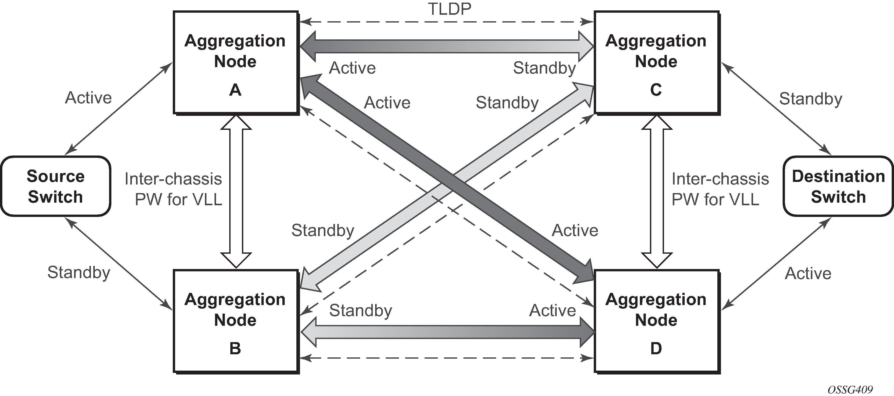
It is important to note that to provide protection if the active SDP between node A and D fails and the need to limit the number of lost data for LI the ICB between node A and B must be supported. As a result, when the SDP connecting nodes A and D fails the data on its way from the source switch to node A and the data in node A must be directed by the ICB to node B and from there to node D.
This functionality is already supported in when providing pseudo wire redundancy for VLLs and must be extended to mirror or LI service redundancy.
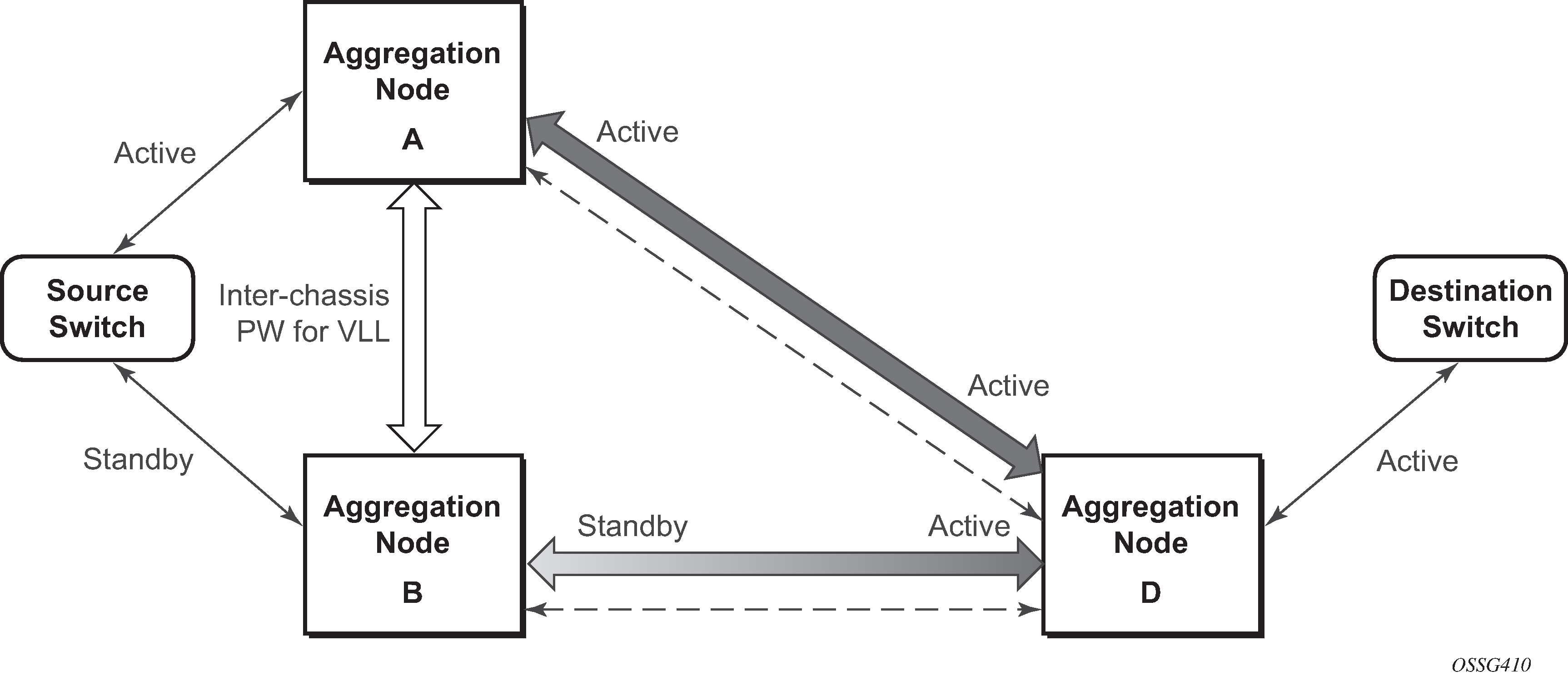
The notable difference with scenarios standard pseudo wire redundancy scenarios is that provided the customer service is redundant on nodes A and B (State engine for redundant service to a redundant mirror service and State engine for redundant service to a non-redundant mirror service) both aggregation node A and Aggregation node B maintain an active Pseudo wire to Node D who in turn has an active link to the destination switch. If in State engine for redundant service to a redundant mirror service, the link between D and the destination switch is disconnected, then both aggregation A and B must switch to use pseudowire connection to Node C.
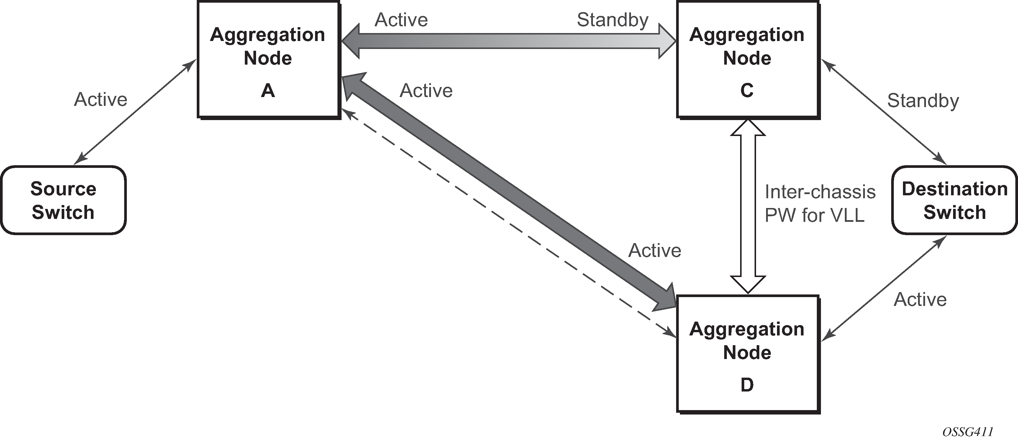
In the case where a non-redundant service is being mirrored to a redundant mirror service (State engine for a non-redundant service to a redundant mirror service ) the source aggregation node (A) can only maintain a pseudo wire to the active destination aggregation node (D). Should the link between aggregation node D and the destination switch fail then the pseudo wire must switch to the new active aggregation node (C).
Redundant mirror source notes
A redundant remote mirror service destination is not supported for IP mirrors (a set of remote IP mirror destinations). The remote destination of an IP mirror is a VPRN instance, and an ‟endpoint” cannot be configured in a VPRN service.
A redundant mirror source is supported for IP mirrors, but the remote destination must be a single node (a set of mirror source nodes, each with a mirror destination that points to the same destination node). In this case the destination node would have a VPRN instance with multiple ip-mirror-interfaces.
Multi Chassis APS (MC-APS) groups cannot be used as the SAP for a redundant remote mirror destination service. APS cannot be used to connect the remote mirror destination SR nodes to a destination switch.
Multi Chassis APS (MC-APS) groups can be used as the SAP for a redundant mirror service source. APS can be used to redundantly connect the source of the mirrored traffic to the SR nodes that are behaving as the mirror-sources.
Configuration process overview
Mirroring can be performed based on the following criteria:
Configuring mirroring is like creating a unidirection service. Mirroring requires the configuration of:
- mirror source
- the traffic on specific points to mirror
- mirror destination
- the location to send the mirrored traffic, where the sniffer is to be located
Local mirroring example shows a local mirror service configured on ALA-A.
Port 2/1/2 is specified as the source. Mirrored traffic ingressing and egressing this port is sent to port 2/1/3.
SAP 2/1/3 is specified as the destination. The sniffer is physically connected to this port. Mirrored traffic ingressing and egressing port 2/1/2 is sent here. SAP, encapsulation requirements, packet slicing, and mirror classification parameters are configured. SDPs are not used in local mirroring.
Figure 13. Local mirroring example 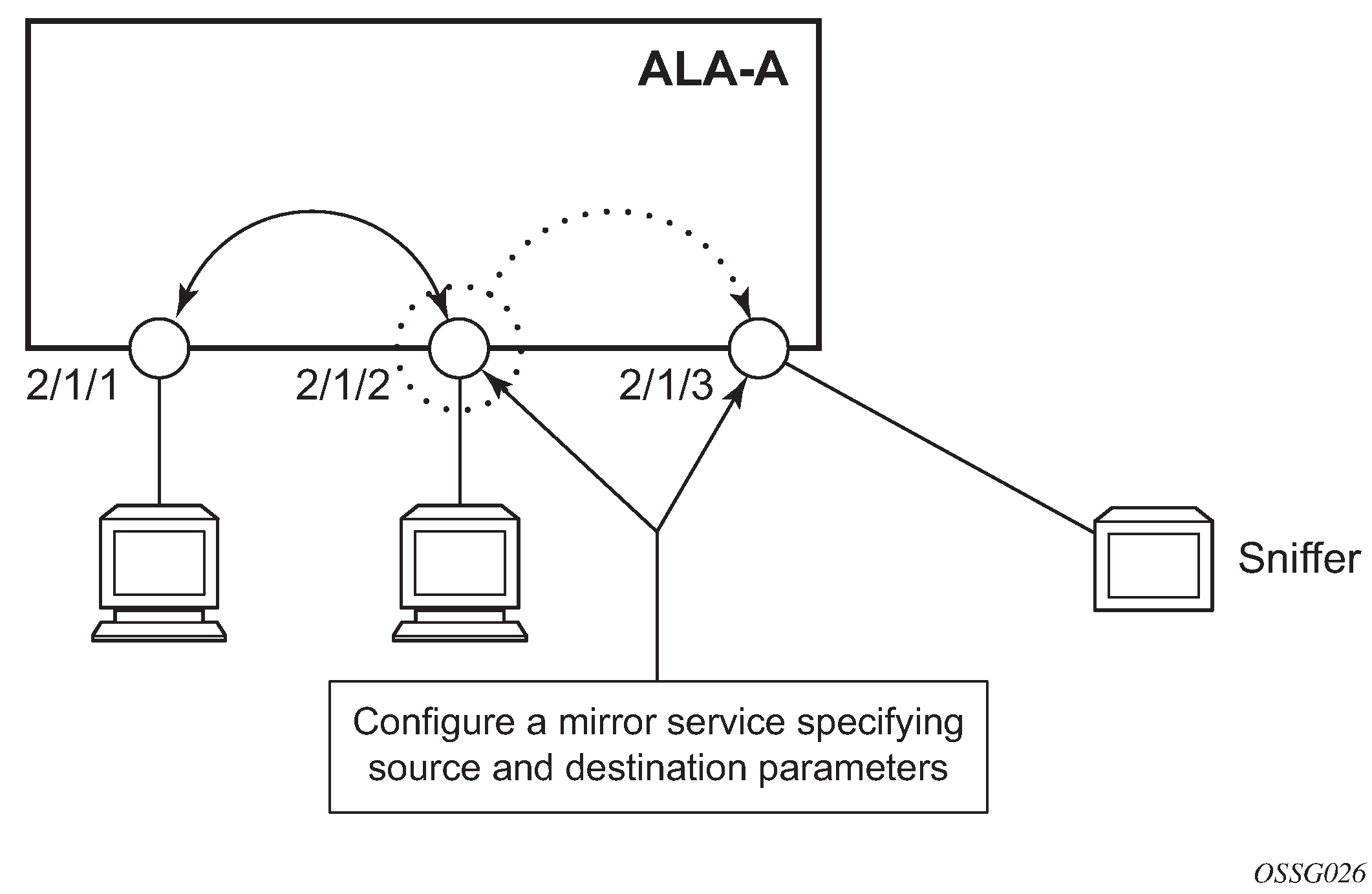
Remote mirroring example shows a remote mirror service configured as ALA B as the mirror source and ALA A as the mirror destination. Mirrored traffic ingressing and egressing port 5/2/1 (the source) on ALA B is handled the following ways:
-
Port 5/2/1 is specified as the mirror source port. Parameters are defined to select specific traffic ingressing and egressing this port.
-
Destination parameters are defined to specify where the mirrored traffic is to be sent. In this case, mirrored traffic is sent to a SAP configured as part of the mirror service on port 3/1/3 on ALA A (the mirror destination).
-
ALA A decodes the service ID and sends the traffic out of port 3/1/3.
-
The sniffer is physically connected to this port (3/1/3). SAP, encapsulation requirements, packet slicing, and mirror classification parameters are configured in the destination parameters.
Figure 14. Remote mirroring example 
Mirror configuration and implementation flow shows the process to provision basic mirroring parameters.
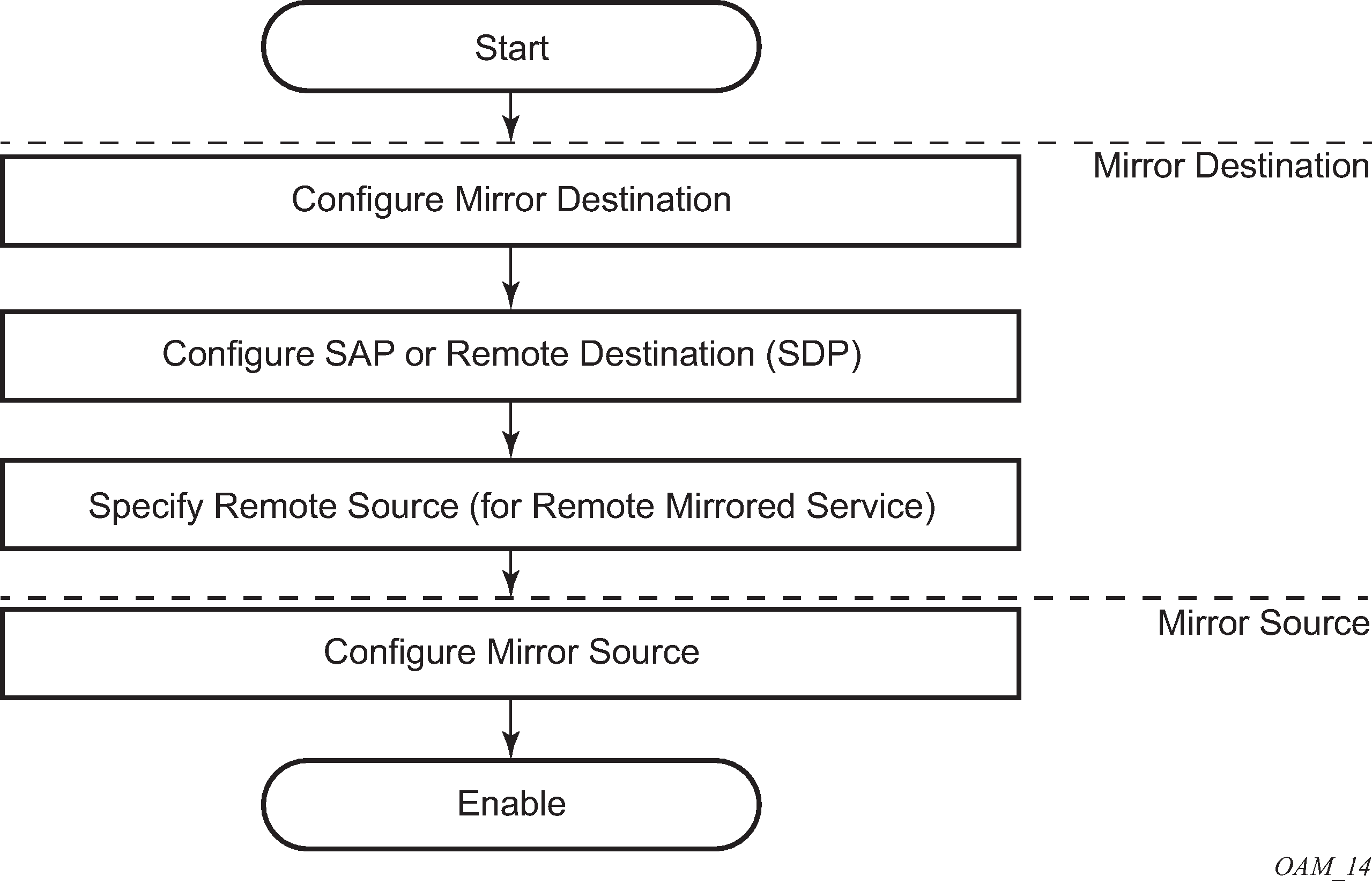
Lawful intercept configuration and implementation flow shows the process to provision LI parameters.
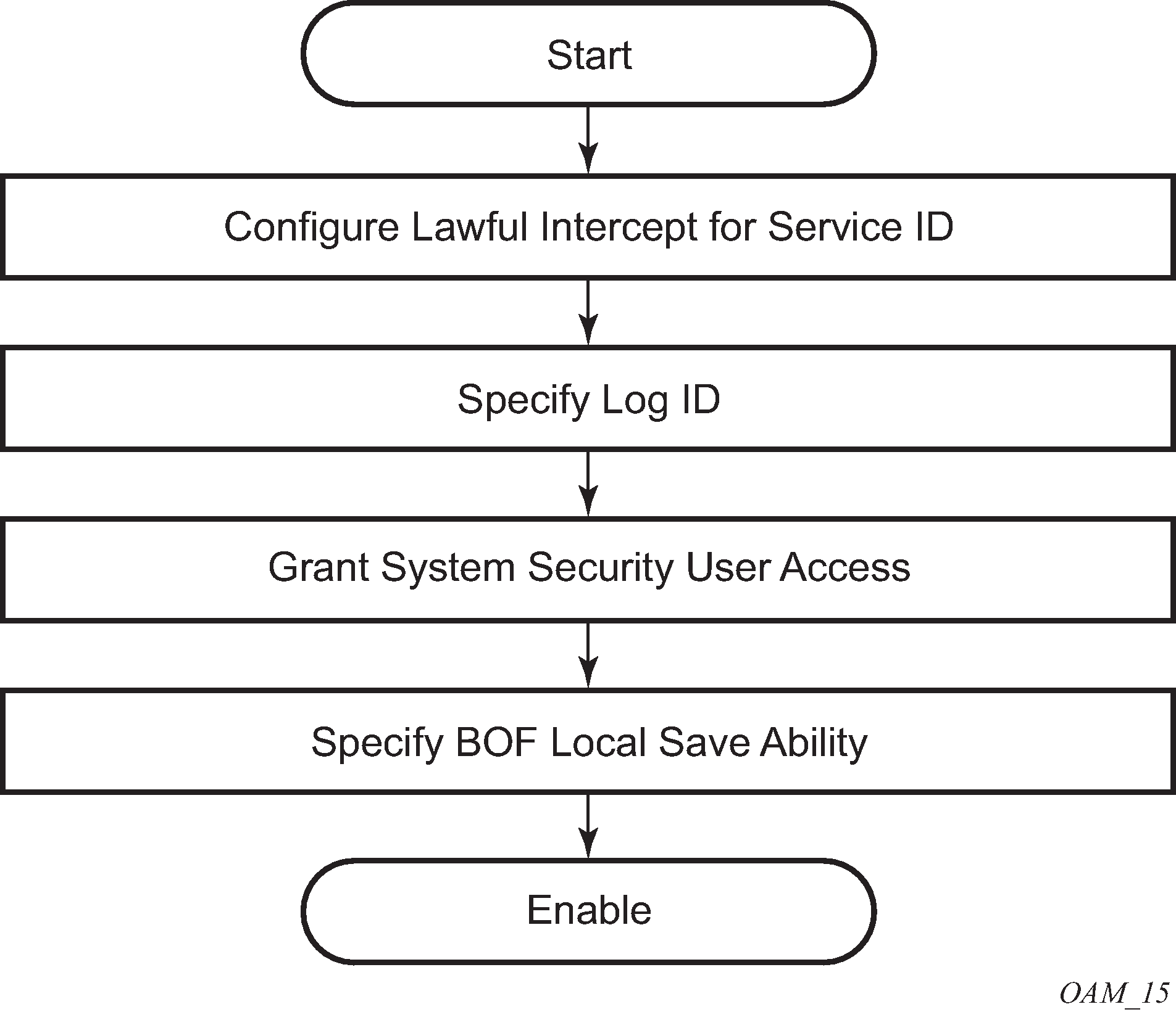
Configuration notes
This section describes mirroring configuration restrictions:
Multiple mirroring service IDs (mirror destinations) may be created within a single system.
A mirrored source can only have one destination.
Both destination mirroring service IDs (including service parameters) and config mirror source (defined in config>mirror>mirror-source) are persistent between router (re)boots and are included in the configuration saves.
Debug mirror source (defined debug>mirror>mirror-source) and lawful intercept source (defined in config>li>li-source) criteria configurations are not preserved in a configuration save (admin save). Debug mirror source configuration can be saved using admin>debug-save. Lawful intercept source configuration can be saved using config>li>save.
Subscriber based lawful intercept source criteria is persistent across creation/existence of the subscriber. Filter or SAP-based LI source criteria is removed from the LI source configuration if the filter entry or SAP is deleted. Applies to the 7450 ESS and 7950 SR.
Physical layer problems such as collisions, jabbers, and so on, are not mirrored. Typically, only complete packets are mirrored.
Starting and shutting down mirroring:
mirror destinations
The default state for a mirror destination service ID is shutdown. Execute a no shutdown command to enable the feature.
When a mirror destination service ID is shutdown, mirrored packets associated with the service ID are not accepted from its mirror source or remote source. The associated mirror source is put into an operationally down mode. Mirrored packets are not transmitted out the SAP or SDP. Each mirrored packet is silently discarded. If the mirror destination is a SAP, the SAP’s discard counters are incremented.
Issuing the shutdown command causes the mirror destination service or its mirror source to be put into an administratively down state. Mirror destination service IDs must be shut down first to delete a service ID, or SAP, or SDP association from the system.
mirror sources
The default state for a mirror source for a mirror-dest service ID is no shutdown. Enter a shutdown command to deactivate (disable) mirroring from that mirror-source.
Mirror sources do not need to be shutdown to remove them from the system. When a mirror source is shutdown, mirroring is terminated for all sources defined locally for the mirror destination service ID.
The following are lawful intercept configuration restrictions.
To address network management, operators without LI permission cannot view or manage the LI data on the node nor can they view or manage the data on the Network Management platform.
Entries within LI filters (li-ip-filter, li-ipv6-filter, and li-mac-filter) are typically used to match a specific IP or MAC address as LI targets. When these LI filters are associated with a filter in the main configuration region (ip-filter, ipv6-filer, or mac-filter), the system does not insert the entries in a sequence for performance reasons. For example, it is possible that filter entry 2 can take place before filter entry 1. This does not affect the LI functionality. However, in cases where the entries overlap, it is possible for a latter entry to first match the IP or the MAC address.
LI mirroring does not allow the configuration of ports and ingress labels as a source parameter.
Configuring service mirroring with CLI
This section provides information about service mirroring.
Mirror configuration overview
SR OS mirroring can be organized in the following logical entities:
The mirror source is defined as the location where ingress or egress traffic specific to a port, SAP, MAC, or IP filter, ingress label or a subscriber is to be mirrored (copied). The original frames are not altered or affected in any way.
An SDP is used to define the mirror destination on the source router to point to a remote destination (another router).
A SAP is defined in local and remote mirror services as the mirror destination to where the mirrored packets are sent.
The subscriber contains hosts which are added to a mirroring service (applies to the 7450 SR and 7750 SR only).
Defining mirrored traffic
In some scenarios, like using VPN services or when multiple services are configured on the same port, specifying the port does not provide a sufficient resolution to separate traffic. In Nokia’s implementation of mirroring, multiple source mirroring parameters can be specified to further identify traffic.
Mirroring of packets matching specific filter entries in an IP or MAC filter can be applied to refine what traffic is mirrored to flows of traffic within a service. The IP criteria can be combinations of:
source IP address and mask
destination IP address and mask
IP protocol value
source port value and range (for example, UDP, or TCP port)
destination port value and range (for example, UDP, or TCP port)
DiffServ Code Point (DSCP) value
ICMP code
ICMP type
IP fragments
IP option value and mask
single or multiple IP option fields present
IP option fields present
TCP ACK set/reset
TCP SYN set/reset
SAP ingress/egress labels
The MAC criteria can be combinations of:
IEEE 802.1p value and mask
source MAC address and mask
destination MAC address and mask
Ethernet Type II Ethernet type value
Ethernet 802.2 LLC DSAP value and mask
Ethernet 802.2 LLC SSAP value and mask
IEEE 802.3 LLC SNAP Ethernet frame OUI zero or non-zero value
IEEE 802.3 LLC SNAP Ethernet frame PID value
SAP ingress/egress labels
Lawful Intercept configuration overview
Lawful Intercept allows the user to access and execute commands at various command levels based on profiles assigned to the user by the administrator. LI must be configured in the config>system>security>user>access and config>system>security>profile contexts. The options include FTP, SNMP, console, and LI access.
LI parameters configured in the BOF context (li-local-save and li-separate) include the ability to access LI separately than the normal administrator. As with all BOF entities, changing the BOF file during normal system operation only results in the parameter being set for the next reboot. These BOF commands are initialized to the default values, no li-separate and no-li-local-save. A system boot is necessary for any change to the li-separate and li-local-save to become effective.
Changes to the li-separate and li-local-save configurations should be made in both primary and backup CM BOF files.
At regular intervals, a LI status event is generated by the system to indicate the mode of the LI administration, time of the last reboot, and whether local save is enabled.
Saving LI data
Depending on location and law enforcement preferences, the node can be configured to save all LI data on local media. If the operator saves this data then when starting or restarting the system the configuration file is processed first and then the LI configuration is restarted.
When permitted to save the data, the data is encrypted using AES. The encryption key is unique per system and is not visible to any administrator.
To save LI data locally, the option must be configured in the bof>li-local-save context. Enabling this option is only be applied after a system reboot.
If an LI save is permitted, then only a local save is permitted and, by default, it is saved to Compact Flash 3 with the filename of li.cfg. An explicit save command under the config>li context must be executed to save the LI. An LI administrator with privileges to configure LI, can execute the li.cfg file.
Regulating LI access
Depending on local regulations pertaining to Lawful Intercept (LI) a node can be configured to separate normal system administration tasks from tasks of a Lawful Intercept operator.
If the separation of access is not required and any administrator can manage lawful intercept or plain mirroring, then it is not necessary to configure the li-separate parameter in the BOF configuration. However, to ensure logical separation, the following must occur:
-
An administrator must create a user and configure the user as LI capable (config>system>security>user>access context). Furthermore, the administrator must assure that both CLI and SNMP access permission is granted for the LI operator.
-
Finally, before turning the system into two separate administration domains, the CLI user must be granted a profile that limits the LI operator to those tasks relevant to the job (config>system> security>profile>li context).
It is important to remember that the LI operator is the only entity who can grant LI permission to any other user when in li-separate mode.
Provided the above procedure is followed, the LI administrator must decide whether to allow the LI (source) configuration to be saved onto local media. This is also subject to local regulations.
At this point, the BOF file can be configured with the li-separate and li-local-save parameters. If the local save is not configured then the LI information must be reconfigured after a system reboot.
Assuming li-separate is configured, the node should be rebooted to activate the separate mode. At this point the system administrators without LI permission cannot modify, create or view any LI- specific configurations. For this to occur, the BOF file must be reconfigured and the system rebooted. This combined with other features prohibits an unauthorized operator from modifying the administrative separation without notifying the LI administrator.
The following example shows an SNMP configuration with views, access groups, and attempts parameters.
A:ALA-23>config>system>security>snmp# info detail
----------------------------------------------
                view iso subtree 1
                    mask ff type included
                exit
                view no-security subtree 1
                    mask ff type included
                exit
                view no-security subtree 1.3.6.1.6.3
                    mask ff type excluded
                exit
                view no-security subtree 1.3.6.1.6.3.10.2.1
                    mask ff type included
                exit
                view no-security subtree 1.3.6.1.6.3.11.2.1
                    mask ff type included
                exit
                view no-security subtree 1.3.6.1.6.3.15.1.1
                    mask ff type included
                exit
...
                access group "snmp-li-ro" security-model usm security-
level privacy context "li" read "li-view" notify "iso"
                access group "snmp-li-rw" security-model usm security-
level privacy context "li" read "li-view" write "li-view" notify "iso"
                attempts 20 time 5 lockout 10
...
----------------------------------------------
A:ALA-23>config>system>security>snmp#
The following example shows a user account configuration.
A:ALA-23>config>system>security# info
----------------------------------------------
...
    user "liuser"
        access console snmp li
        console
            no member "default"
            member "liprofile"
        exit
        snmp
            authentication md5 <auth-key> privacy des <priv-key>
            group "snmp-li-rw"
        exit
   exit
...
----------------------------------------------
A:ALA-23>config>system>security#
LI user access
By default, LI user access is limited to those commands that are required to manage LI functionality. If a user is granted permission to access other configuration and operational data, then this must be explicitly configured in the user profile of the LI operator in the config>system>security>profile>entry>match command-string context. Creating an LI operator account shows the work flow to set an LI operator.
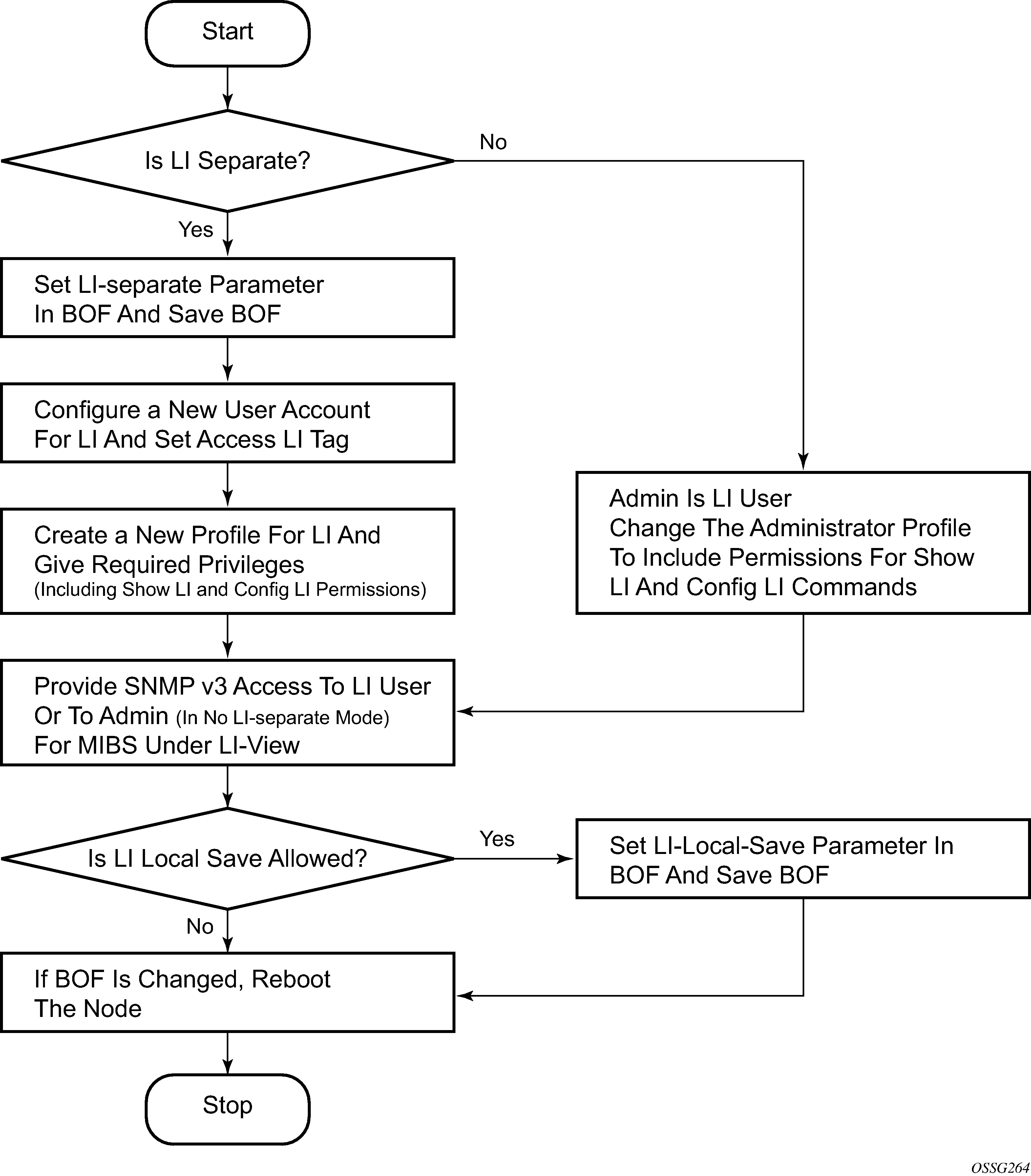
LI source configuration
Filter configuration is accessible to both the LI operator and regular system administrators. If the content of a filter list that is subject to an LI operation and if a filter (included in the filter list) is used by an LI operator, its contents cannot be modified unless the li-filter-lock-state is unlocked, see Configurable filter lock for Lawful Intercept. If an attempt is made, then an LI event is generated. An LI source can contain many LI filter entries. In general, an LI source can only associate with one mirror destination service. A mirror destination can be associated with one source: debug mirror source, config mirror source, or LI mirror source. When a mirror destination is referenced by a source, the mirror destination cannot be referenced again.
In the configuration, when an LI operator specifies that an entry must be used as an LI entry then this fact is hidden from all non-LI operators. Modification of a filter entry is not allowed if it is used by LI, see Configurable filter lock for Lawful Intercept. However, an event is generated, directed to the LI operator, indicating that the filter has been compromised.
Debug mirroring source has the lowest priority compared to both config mirror source and li source, for example, when a SAP is referenced in a debug mirror source. It is possible for the config mirror source or li source to reference the same SAP. The debug mirror source SAP is silently deleted.
The following order applies for both ingress and egress traffic:
port mirroring (debug only)
SAP mirroring (debug or LI)
subscriber mirroring (debug or LI) for the 7450 ESS and 7750 SR
filter mirroring (debug or LI)
For frames from network ports:
port mirroring (debug only)
label mirroring (debug only, ingress only)
filter mirroring (debug or LI)
Filters can be created by all users that have access to the relevant CLI branches.
When an LI mirror source using a specific service ID is created and is in the no shutdown state, the corresponding mirror destination on the node cannot be modified (including shutdown/no shutdown commands) or deleted.
In the separate mode, the anonymity of the source is protected. After source criterion is attached to the LI source, the following applies:
In SAP configurations, only modifications that stop the flow of LI data while the customer receives data is blocked unless the li-filter-lock-state is unlocked, see Configurable filter lock for Lawful Intercept.
In filter configurations, if a filter entry is attached to the LI source, modification and deletion of both the filter and the filter entry are blocked.
Configurable filter lock for Lawful Intercept
With the default Lawful Intercept configuration, when a filter entry is used as a Lawful Intercept (LI) mirror source criteria/entry, all subsequent attempts to modify the filter are then blocked to avoid having the LI session impacted by a non-LI user.
A configurable LI parameter allows an LI user to control the behavior of filters when they are used for LI.
Configuration of the li-filter-lock-state allows an operator to control whether modifications to filters that are being used for LI are allowed by no users, all users or li users only.
LI MAC filter configuration
Although normal MAC filter entries (configured under config>filter>mac-filter) can be referenced in an li-source, there is also the option to configure and use special-purpose Lawful Intercept MAC filters.
LI MAC filters are configured in the protected config>li CLI branch.
LI MAC filters are associated by configuration with normal MAC filters, and entries created in the LI MAC filters are inserted into the associated normal MAC filter before the filter is downloaded to the data plane hardware and applied. The combined filter list is not visible to any users which maintains a separation between LI operators and operators doing other normal filter configuration work (for example, interface ACLs).
A configurable li-filter-block-reservation is used to reserve a range of entries in the normal filter into which the LI entries are inserted.
LI logging
A logging collector is supported in addition to existing main, security, change, and debug log collectors. LI log features include the following:
Only visible to LI operators (such as show command output).
Encrypted when transmitted (SNMPv3).
Logging ability can only be created, modified, or deleted by an LI operator.
The LI user profile must include the ability to manage the LI functions.
Basic mirroring configuration
Destination mirroring parameters must include at least:
a mirror destination ID (same as the mirror source service ID)
a mirror destination SAP or SDP
Mirror source parameters must include at least:
a mirror service ID (same as the mirror destination service ID)
one source type (port, SAP, ingress label, IP filter or MAC filter) specified
The following example shows a configuration of a local mirrored service where the source and destinations are on the same device (ALA-A).
*A:ALA-A>config>mirror# info
----------------------------------------------
        mirror-dest 103 create
            sap 2/1/25:0 create
egress
                    qos 1
                exit
            exit
            no shutdown
        exit
----------------------------------------------
*A:ALA-A>config>mirror#
The following examples shows a mirror source configuration:
*A:ALA-A>debug>mirror-source# show debug mirror
debug
    mirror-source 103
        port 2/1/24 egress ingress
no shutdown
    exit
exit
*A:ALA-A>debug>mirror-source# exit
The following example shows a configuration of a remote mirrored service where the source is a port on ALA-A and the destination is a SAP is on ALA-B:
*A:ALA-A>config>mirror# info
----------------------------------------------
        mirror-dest 1000 create
            spoke-sdp 2:1 egr-svc-label 7000
            no shutdown
        exit
----------------------------------------------
*A:ALA-A>config>mirror# exit all
*A:ALA-A# show debug
debug
    mirror-source 1000
        port 2/1/2 egress ingress
no shutdown
    exit
exit
*A:ALA-A#


*A:ALA-B>config>mirror# info
----------------------------------------------
        mirror-dest 1000 create
            remote-source
                far-end 10.10.10.104 ing-svc-label 7000
            exit
            sap 3/1/2:0 create
egress
                    qos 1
                exit
            exit
            no shutdown
        exit
----------------------------------------------
*A:ALA-B>config>mirror#
Mirror classification rules
Nokia’s implementation of mirroring can be performed by configuring parameters to select network traffic according to any of the following entities.
Port
The port command associates a port to a mirror source. The port is identified by the port ID.
The following shows the port-id syntax for the port command:
| port-id: | slot/mda/port[.channel] | ||
|---|---|---|---|
|
eth-sat-id |
esat-id/slot/port |
||
|
esat |
keyword |
||
|
id |
1 to 20 |
||
|
pxc-id |
pxc-id.sub-port |
||
|
pxc |
keyword |
||
|
id |
1 to 64 |
||
|
sub-port |
a, b |
||
|
aps-id |
aps-group-id[.channel] |
||
|
aps |
keyword |
||
|
group-id |
1 to 64 |
||
|
bundle-type-slot/mda.bundle-num |
|||
|
bundle |
keyword |
||
|
type |
ima, fr ppp |
||
|
bundle-num |
1 to 336 |
||
|
ccag-id - ccag-id.path-id[cc-type]:cc-id |
|||
|
ccag |
keyword |
||
|
id |
1 o 8 |
||
|
path-id |
a,b |
||
|
cc-type |
.sap-net, .net-sap |
||
|
cc-id |
0 to 4094 |
||
|
lag-id |
1 to 800 |
||
|
egress |
keyword |
||
|
ingress |
keyword |
||
The defined port can be an Ethernet port, a SONET/SDH path, a multilink bundle, a TDM channel, a Cross Connect Aggregation Group (CCAG), or a Link Aggregation Group (LAG) ID. If the port is a SONET/SDH or TDM channel, the channel ID must be specified to identify which channel is being mirrored. When a LAG ID is specified as the port ID, mirroring is enabled on all ports making up the LAG. Ports that are circuit-emulation (CEM) and PPP bundle groups cannot be used in a mirror source (applies to the 7750 SR). SONET/SDH applies to the 7450 ESS and 7750 SR, and multilink bundle and TDM channel apply to the 7750 SR.
Mirror sources can be ports in either access or network mode. Port mirroring is supported in the following combinations:
| Port type | Port mode | Port encapsulation type |
|---|---|---|
|
faste/gige/xgige Ethernet |
access |
dot1q, null, qinq |
|
faste/gige/xgige Ethernet |
network |
dot1q, null |
|
SONET (clear/deep channel) |
access |
bcp-null, bcp-dot1q, ipcp |
|
TDM (clear/deep channel) |
access |
bcp-null, bcp-dot1q, ipcp |
debug>mirror-source# port {port-id | lag lag-id}
 {[egress][ingress]}
*A:ALA-A>debug>mirror-source# port 2/2/2 ingress egressSAP
More than one SAP can be associated within a single mirror-source. Each SAP has its own ingress and egress parameter keywords to define which packets are mirrored to the mirror-dest service ID. A SAP that is defined within a mirror destination cannot be used in a mirror source.
debug>mirror-source# sap sap-id {[egress] [ingress]}*A:ALA-A>debug>mirror-source# sap 2/1/4:100 ingress
egressor debug>mirror-source# port 2/2/1.sts12 ingressMAC filter
MAC filters are configured in the config>filter>mac-filter context. The mac-filter command causes all the packets matching the explicitly defined list of entry IDs to be mirrored to the mirror destination specified by the service-id of the mirror source.
debug>mirror-source# mac-filter mac-filter-id entry
 entry-id [entry-id …]
*A:ALA-2>debug>mirror-source# mac-filter 12 entry 15 20 25IP filter
IP filters are configured in the config>filter>ip-filter or config>filter>ipv6-filter context. The ip-filter command causes all the packets matching the explicitly defined list of entry IDs to be mirrored to the mirror destination specified by the service-id of the mirror source.
Ingress mirrored packets are mirrored to the mirror destination before any ingress packet modifications. Egress mirrored packets are mirrored to the mirror destination after all egress packet modifications.
debug>mirror-source# ip-filter ip-filter-id entry entry-
 id [entry-id …]
debug>mirror-source# ipv6-filter ipv6-filter-id entry
 entry-id [entry-id...]
*A:ALA-A>debug>mirror-source# ip-filter 1 entry 20 Ingress label
The ingress-label command is used to mirror ingressing MPLS frames with the specified MPLS labels. The supported MPLS labels are LDP, RSVP, and LDP over RSVP. The ingress label must be at the top of the label stack and can only be mirrored to a single mirror destination. If the same label is defined with multiple mirror destinations, an error is generated and the original mirror destination does not change. The ingress-label allows packets matching the ingress label to be duplicated (mirrored) and forwarded to the mirror destination. The ingress label must be active before it can be used as mirror source criteria. If the ingress label is not used in the router, the mirror source removes the ingress label automatically.
debug>mirror-source# ingress-label label [label...]*A:ALA-A>debug>mirror-source# ingress-label 103000 1048575Subscriber
The subscriber command is used to add hosts of a subscriber to a mirroring service. This command applies to the 7450 ESS and 7750 SR only.
debug>mirror-source# subscriber sub-ident-string
 [sap...]

config>mirror>mirror-source# subscriber sub-ident-string
[sap...] Common configuration tasks
This section provides a brief overview of the tasks that must be performed to configure both local and remote mirror services and provides the CLI command syntax. Note that local and remote mirror source and mirror destination components must be configured under the same service ID context.
Configuring a local mirror service
To configure a local mirror service, the source and destinations must be located on the same router. Note that local mirror source and mirror destination components must be configured under the same service ID context.
The mirror-source commands are used as traffic selection criteria to identify traffic to be mirrored at the source. Each of these criteria are independent. For example, in the same mirror-source an entire port X could be mirrored at the same time as packets matching a filter entry applied to SAP Y could be mirrored. A filter must be applied to the SAP or interface if only specific packets are to be mirrored. Note that slice-size is not supported by CEM encap-types or IP-mirroring (only applies to the 7750 SR and 7950 XRS).
Use the CLI syntax to configure one or more mirror source parameters:
The mirror-dest commands are used to specify where the mirrored traffic is to be sent, the forwarding class, and the size of the packet.
The following output shows an example of a local mirrored service. On ALA-A, mirror service 103 is mirroring traffic matching IP filter 2, entry 1 as well as egress and ingress traffic on port 2/1/24 and sending the mirrored packets to SAP 2/1/25:
*A:ALA-A>config>mirror# info
----------------------------------------------
        mirror-dest 103 create
            sap 2/1/25:0 create
egress
                    qos 1
                exit
            exit
            no shutdown
        exit
----------------------------------------------
*A:ALA-A>config>mirror#
The following output shows debug mirroring information:
*A:ALA-A>debug>mirror-source# show debug mirror
debug
    mirror-source 103
        no shutdown
        port 2/1/24 egress ingress
        ip-filter 2 entry 1
    exit
exit
*A:ALA-A>debug>mirror-source# exit
The following output shows using config mirror source as an alternative:
*A:ALA-A>config>mirror# info
    mirror-source 103
        no shutdown
        port 2/1/24 egress ingress
        ip-filter 2 entry 1
    exit
The IP filter and entry referenced by the mirror source must exist and must be applied to an object for traffic to be mirrored:
*A:ALA-A>config>service>vprn>if# info
----------------------------------------------
                sap 1/1/3:63 create
                    ingress
                        filter ip 2
                    exit
                exit
----------------------------------------------
Configuring SDPs for mirrors and LI
This section provides a brief overview of the tasks that must be performed to configure SDPs and provides the CLI commands. For more information about service configuration, see the 7450 ESS, 7750 SR, 7950 XRS, and VSR Services Overview Guide.
Consider the following SDP characteristics:
Configure GRE, MPLS, MPLS-TP, or L2TPv3 SDPs.
Each distributed service must have an SDP defined for every remote SR to provide Epipe, VPLS, or mirrored services.
A distributed service must be bound to an SDP. By default, no SDP is associated with a service. After an SDP is created, services can be associated with that SDP.
An SDP is not specific to any one service or any type of service. An SDP can have more than one service bound to it.
When using L2TPv3, MPLS-TP, or LDP IPv6 LSP SDPs in a remote mirroring solution, configure the destination node with remote-src>spoke-sdp entries. For all other types of SDPs use remote-src>far-end entries.
To configure an MPLS SDP, LSPs must be configured first and then the LSP-to-SDP association must be explicitly created.
Configuring basic SDPs
To configure a basic SDP, perform the following steps:
- Select an originating node.
- Create an SDP ID.
- Select an encapsulation type.
- Select the far-end node.
Configuring return path SDPs
To configure the return path SDP, perform the same steps on the far-end router:
- Select an originating node.
- Create an SDP ID.
- Select an encapsulation type.
- Select the far-end node.
config>service# sdp sdp-id [gre | mpls | l2tpv3 | gre-eth-bridged] create
description description-string
far-end ip-address|ipv6-address
lsp lsp-name [lsp-name]
path-mtu octets
no shutdown
keep-alive
hello-time seconds
hold-down-time seconds
max-drop-count count
message-length octets
no shutdown
timeout timeout
On the mirror source router, configure an SDP pointing toward the mirror destination router (or use an existing SDP).
On the mirror destination router, configure an SDP pointing toward the mirror source router (or use an existing SDP).
The following example shows SDP configurations on both the mirror source and mirror destination routers.
*A:ALA-A>config>service# info
-------------------------------------------
sdp 1 create
            description "to-10.10.10.104"
            far-end 10.10.10.104
            no shutdown
        exit
-------------------------------------------
*A:ALA-A>config>service#

*A:ALA-B>config>service# info
----------------------------------------------
        sdp 4 create
            description "to-10.10.10.103"
            far-end 10.10.10.103
            no shutdown
        exit
-------------------------------------------
*A:ALA-B>config>service#
Configuring a remote mirror service
For remote mirroring, the source and destination are configured on the different routers. Note that mirror source and mirror destination parameters must be configured under the same service ID context.
When using L2TPv3, MPLS-TP or LDP IPv6 LSP spoke SDPs in a remote mirroring solution, configure the destination node with remote-src>spoke-sdp entries. For all other types of SDPs use remote-src>far-end entries.
Remote mirrored service tasks shows the mirror destination, which is on ALA-A, configuration for mirror service 1216. This configuration specifies that the mirrored traffic coming from the mirror source (10.10.0.91) is to be directed to SAP 4/1/58 and states that the service only accepts traffic from far end 10.10.0.92 (ALA-B) with an ingress service label of 5678. When a forwarding class is specified, then all mirrored packets transmitted to the destination SAP or SDP override the default (be) forwarding class. The slice size limits the size of the stream of packet through the router and the core network.
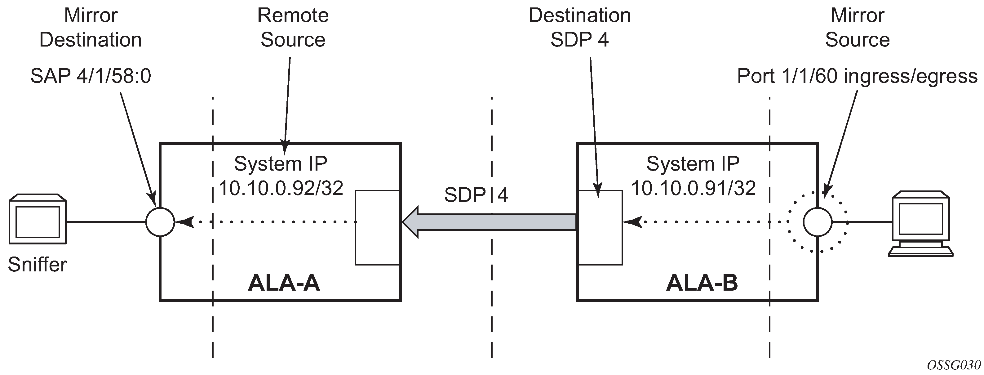
The following example shows the CLI output showing the configuration of remote mirrored service 1216. The traffic ingressing and egressing port 1/1/60 on 10.10.0.92 (ALA-B) is mirrored to the destination SAP 1/1/58:0 on ALA-A.
*A:ALA-A>config>mirror# info
----------------------------------------------
        mirror-dest 1216 create
            description "Receiving mirror traffic from .91"
            remote-source
                far-end 10.10.0.91 ing-svc-label 5678
            exit
            sap 1/1/58:0 create
                egress
                    qos 1
                exit
            exit
            no shutdown
        exit
----------------------------------------------
*A:ALA-A>config>mirror#
The following example shows the remote mirror destination configured on ALA-B:
*A:ALA-B>config>mirror># info
----------------------------------------------
mirror-dest 1216 create
description "Sending mirrored traffic to .92"
fc h1
spoke-sdp 4:60 create
egress
vc-label 5678
exit
no shutdown
exit
slice-size 128
no shutdown
exit
----------------------------------------------
*A:ALA-B>config>mirror#
The following example shows the mirror source configuration for ALA-B:
*A:ALA-B# show debug mirror
debug
        mirror-source 1216
        port 1/1/60 egress ingress
        no shutdown
    exit
exit
*A:ALA-B#
The following example is an alternative for mirror source configuration:
*A:ALA-B# config>mirror#info
        mirror-source 1216
        port 1/1/60 egress ingress
        no shutdown
    exit
*A:ALA-B#
The following example shows the SDP configuration from ALA-A to ALA-B (SDP 2) and the SDP configuration from ALA-B to ALA-A (SDP 4):
*A:ALA-A>config>service>sdp# info
---------------------------------------------
            description "GRE-10.10.0.91"
            far-end 10.10.0.01
            no shutdown
---------------------------------------------
*A:ALA-A>config>service>sdp#


*A:ALA-B>config>service>sdp# info
----------------------------------------------
            description "GRE-10.10.20.92"
            far-end 10.10.10.103
            no shutdown
----------------------------------------------
*A:ALA-B>config>service>sdp#
Configuring Lawful Intercept parameters
The following example shows an LI source configuration and LI log configuration examples:
A:ALA-48>config# info
#--------------------------------------------------
...
(LI  Source Config)
        li-source 1
            sap 1/5/5:1001 egress ingress
            no shutdown
        exit
        li-source 2
            subscriber "test" sla-profile "test" fc l2 ingress egress
            no shutdown
        exit
        li-source 3
            mac-filter 10 entry 1
            no shutdown
        exit
        li-source 4
            ip-filter 11 entry 1
            no shutdown
        exit
...
(LI Log Config)
        log-id 1
                filter 1
                from li
                to session
            exit
            log-id 11
                from li
                to memory
            exit
            log-id 12
                from li
                to snmp
            exit
...
#--------------------------------------------------
A:ALA-48>config#
Pseudowire redundancy for mirror services configuration example
A configuration based on State engine for redundant service to a redundant mirror service is described in this section.
The mirror traffic needs to be forwarded from configured debug mirror-source together with mirror-dest/remote-source (ICB or non-ICB) to either SAP endpoint or SDP endpoint.
A SAP endpoint is an endpoint with a SAP and with or without an additional ICB spoke. An SDP endpoint is an endpoint with regular and ICB spokes.
Only one tx-active can be chosen for either SAP endpoint or SDP endpoint. Traffic ingressing into a remote-source ICB has only ingressing traffic while an ICB spoke has only egressing traffic.
The ingressing traffic to a remote-source ICB cannot be forwarded out of another ICB spoke.
The following example shows a high-level summary of a configuration; it is not intended to be syntactically correct:
Node A:
config mirror mirror-dest 100
endpoint X
sdp to-C endpoint X
sdp to-D endpoint X
sdp to-B endpoint X icb   // connects to B’s remote-source IP-A, traffic A->B only
remote-source IP-B icb    // connects to B’s sdp to-A, traffic B->A only

Node B:
config mirror mirror-dest 100
endpoint X
sdp to-C endpoint X
sdp to-D endpoint X
sdp to-A endpoint X icb   // connects to A’s remote-source IP-B, traffic B->A only
remote-source IP-A icb    // connects to Node A’s sdp to-B, traffic A->B only

Node C:
config mirror mirror-dest 100
endpoint X
sap lag-1:0 endpoint  X
sdp to-D endpoint X icb // connects to D’s remote-source IP-C, traffic C->D only
remote-source IP-A
remote-source IP-B
remote-source IP-D icb // connects to D’s sdp to-C, traffic D->C only

Node D:
config mirror mirror-dest 100
endpoint X
sap lag-1:0 endpoint  X
sdp to-C endpoint X icb // connects to C’s remote-source IP-D, traffic D->C only
remote-source IP-A
remote-source IP-B
remote-source IP-C icb // connects to C’s sdp to-D, traffic C->D only
Service management tasks
This section describes service management tasks related to service mirroring.
Modifying a local mirrored service
Existing mirroring parameters can be modified in the CLI. The changes are applied immediately. The service must be shut down if changes to the SAP are made.
The following example shows the commands to modify parameters for a basic local mirroring service:
config>mirror# mirror-dest 103
config>mirror>mirror-dest# shutdown
config>mirror>mirror-dest# no sap
config>mirror>mirror-dest# sap 3/1/5:0 create
config>mirror>mirror-dest>sap$ exit
config>mirror>mirror-dest# fc be
config>mirror>mirror-dest# slice-size 128
config>mirror>mirror-dest# no shutdown
debug# mirror-dest 103
debug>mirror-source# no port 2/1/24 ingress egress
debug>mirror-source# port 3/1/7 ingress egressThe following output shows the local mirrored service modifications:
*A:ALA-A>config>mirror# info
----------------------------------------------
mirror-dest 103 create
            no shutdown
            fc be
            remote-source
            exit
            sap 3/1/5:0 create
egress
                    qos 1
                exit
            exit
            slice-size 128
        exit

*A:ALA-A>debug>mirror-source# show debug mirror
debug
    mirror-source 103
        no shutdown
        port 3/1/7 egress ingress
exit
*A:ALA-A>debug>mirror-source#
Deleting a local mirrored service
Existing mirroring parameters can be deleted in the CLI. A shutdown must be issued on a service level to delete the service. It is not necessary to shut down or remove SAP or port references to delete a local mirrored service.
The following example shows the commands to delete a local mirrored service.
ALA-A>config>mirror# mirror-dest 103
config>mirror>mirror-dest# shutdown
config>mirror>mirror-dest# exit
config>mirror# no mirror-dest 103
config>mirror# exit
Modifying a remote mirrored service
Existing mirroring parameters can be modified in the CLI. The changes are applied immediately. The service must be shut down if changes to the SAP are made.
In the following example, the mirror destination is changed from 10.10.10.2 (ALA-B) to 10.10.10.3 (SR3). Note that the mirror-dest service ID on ALA-B must be shut down first before it can be deleted.
The following example shows the commands to modify parameters for a remote mirrored service:
*A:ALA-A>config>mirror# mirror-dest 104
config>mirror>mirror-dest# remote-source
config>mirror>mirror-dest>remote-source# no far-end
 10.10.10.2
remote-source# far-end 10.10.10.3 ing-svc-label 3500

*A:ALA-B>config>mirror# mirror-dest 104
config>mirror>mirror-dest# shutdown
config>mirror>mirror-dest# exit
config>mirror# no mirror-dest 104

SR3>config>mirror# mirror-dest 104 create
config>mirror>mirror-dest# spoke-sdp 4:60 egress vc-
 label 3500
config>mirror>mirror-dest# no shutdown
config>mirror>mirror-dest# exit all

SR3># debug
debug# mirror-source 104
debug>mirror-source# port 551/1/2 ingress egress
debug>mirror-source# no shutdown
*A:ALA-A>config>mirror# info
----------------------------------------------
mirror-dest 104 create
remote-source
far-end 10.10.10.3 ing-svc-label 3500
exit
sap 2/1/15:0 create
egress
qos 1
exit
exit
no shutdown
exit
A:SR3>config>mirror# info
----------------------------------------------
mirror-dest 104 create
spoke-sdp 4:60 egress vc-label 3500
no shutdown
exit
----------------------------------------------
A:SR3>config>mirror#
A:SR3# show debug mirror
debug
mirror-source 104
no shutdown
port 5/1/2 egress ingress
exit
exit
A:SR3#
Deleting a remote mirrored service
Existing mirroring parameters can be deleted in the CLI. A shut down must be issued on a service level to delete the service. It is not necessary to shut down or remove SAP, SDP, or far-end references to delete a remote mirrored service.
Mirror destinations must be shut down first before they can be deleted.
*A:ALA-A>config>mirror# mirror-dest 105
config>mirror>mirror-dest# shutdown
config>mirror>mirror-dest# exit
config>mirror# no mirror-dest 105
config>mirror# exit

*A:ALA-B>config>mirror# mirror-dest 105
config>mirror>mirror-dest# shutdown
config>mirror>mirror-dest# exit
config>mirror# no mirror-dest 105
config>mirror# exit
In the example, the mirror-destination service ID 105 was removed from the configuration on ALA-A and ALA-B, therefore, it does not appear in the info command output.
*A:ALA-A>config>mirror# info
----------------------------------------------

----------------------------------------------
*A:ALA-A>config>mirror# exit


*A:ALA-B>config>mirror# info
----------------------------------------------

----------------------------------------------
*A:ALA-B>config>mirror# exit
Because the mirror destination was removed from the configuration on ALA-B, the port information was automatically removed from the debug mirror-source configuration.
*A:ALA-B# show debug mirror
debug
exit
*A:ALA-B#