Cflowd
Cflowd overview
Cflowd is a tool used to obtain samples of IPv4, IPv6, MPLS, and Ethernet traffic data flows through a router. Cflowd enables traffic sampling and analysis by ISPs and network engineers to support capacity planning, trends analysis, and characterization of workloads in a network service provider environment.
Cflowd is also useful for traffic engineering, network planning and analysis, network monitoring, developing user profiles, data warehousing and mining, as well as security-related investigations. Collected information can be viewed several ways such as in port, AS, or network matrices, and pure flow structures. The amount of data stored depends on the cflowd configurations.
Cflowd maintains a list of data flows through a router. A flow is a unidirectional traffic stream defined by several characteristics such as source and destination IP addresses, source and destination ports, inbound interface, IP protocol and ToS bits.
When a router receives a packet for which it currently does not have a flow entry, a flow structure is initialized to maintain state information about that flow, such as the number of bytes exchanged, IP addresses, port numbers, AS numbers, and so on. Each subsequently sampled packet matching the same command options of the flow contributes to the byte and packet count of the flow until the flow is terminated and exported to a collector for storage.
Operation
Basic cflowd steps shows the basic operation of the cflowd feature. This sampled flow is only used to describe the basic steps that are performed. It is not intended to specify implementation.
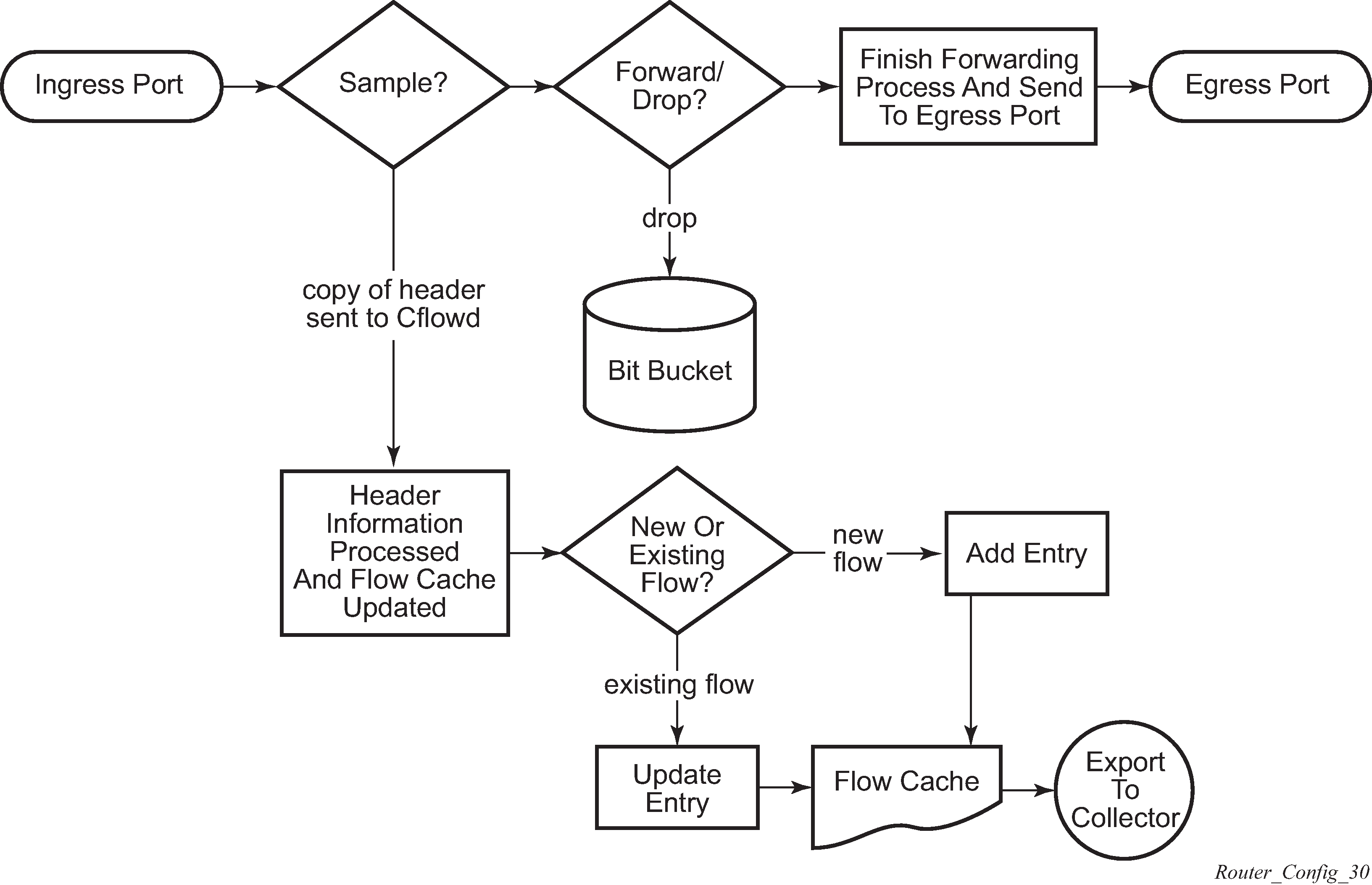
As a packet ingresses a port, a decision is made to sample it or not for cflowd.
The original packet is processed for forwarding as normal and the cflowd sample is sent for processing. If a packet is discarded because of filters actions, an indicator is sent with the cflowd sample to the processing agent.
If a new flow is found, a new entry is added to the cache. If the flow already exists in the cache, the flow statistics are updated.
If a new flow is detected and the maximum number of entries are already in the flow cache, the earliest expiry entry is removed. The earliest expiry entry/flow is the next flow that expires because of the active or inactive timer expiration.
If a flow has been inactive for a period of time equal to or greater than the inactive timer (default 15 s), the entry is removed from the flow cache.
If a flow has been active for a period of time equal to or greater than the active timer (default 30 min), the entry is removed from the flow cache.
When a flow is exported from the cache, the collected data is sent to an external collector, which maintains an accumulation of historical data flows that network users can use to analyze traffic patterns.
Data is exported in one of the following formats:
Version 5
Generates a fixed export record for each individual flow captured.
Version 8
Aggregates multiple individual flows into a fixed aggregate record.
Version 9
Generates a variable export record, depending on user configuration and sampled traffic type (IPv4, IPv6, or MPLS), for each individual flow captured.
Version 10 (IPFIX)
Generates a variable export record, depending on user configuration and sampled traffic type (IPv4, IPv6, or MPLS), for each individual flow captured.
V5, V8, V9, V10, and flow processing shows V5, V8, V9, and V10 flow processing.
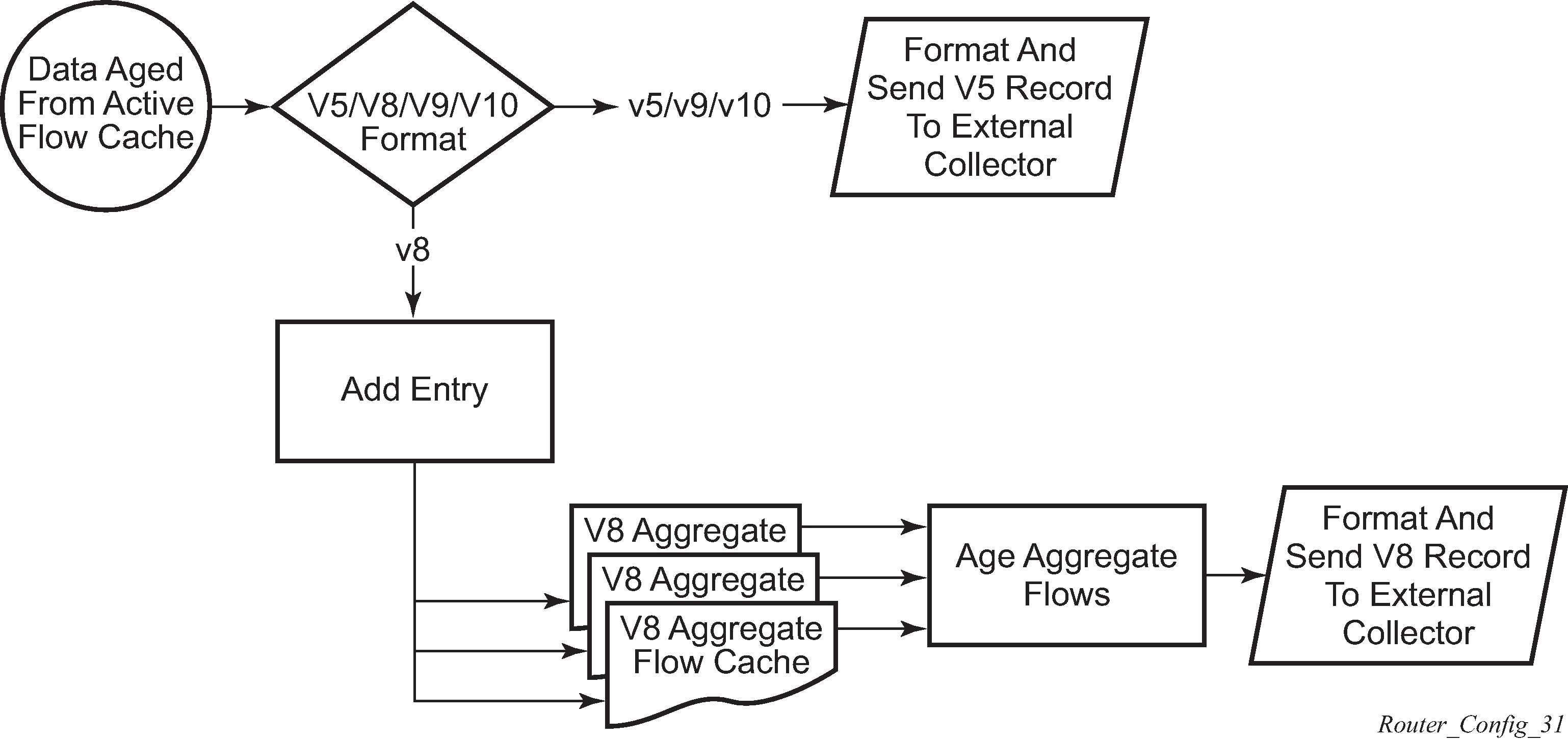
As flows are expired from the active flow cache, the export format must be determined, either V5, V8, V9, and V10.
-
If the export format is V5 or V9 and V10, no further processing is performed and the flow data is accumulated to be sent to the external collector.
-
If the export format is V8, the flow entry is added to one or more of the configured aggregation matrices.
-
As the entries within the aggregate matrices are aged out, they are accumulated to be sent to the external flow collector in V8 format.
The sample rate and cache size are configurable values. The cache size default is 64K flow entries.
A flow terminates when one of the following conditions is met:
When the inactive timeout period expires (default: 15 s). A flow is considered terminated when no packets are seen for the flow for n seconds.
When an active timeout expires (default: 30 s). Default active timeout is 30 min. A flow terminates according to the time duration, regardless of whether there are packets coming in for the flow.
-
When the user executes a clear cflowd command.
When other measures are met that apply to aggressively age flows as the cache becomes too full (such as overflow percent).
Version 8
There are several different aggregate flow types including:
AS matrix
destination prefix matrix
source prefix matrix
prefix matrix
protocol/port matrix
Version 8 is an aggregated export format. As individual flows are aged out of the raw flow cache, the data is added to the aggregate flow cache for each configured aggregate type. Each of these aggregate flows are also aged in a manner similar to the method the active flow cache entries are aged. When an aggregate flow is aged out, it is sent to the external collector in the V8 record format.
Version 9
Version 9 format is a more flexible format and allows for different templates or sets of cflowd data to be sent based on the type of traffic being sampled and the template set configured.
Version 9 is interoperable with RFC 3954, Cisco Systems NetFlow Services Export Version 9.
Version 10
Version 10 is a new format and protocol that interoperates with the specifications from the IETF as the IP Flow Information Export (IPFIX) standard. Like V9, the V10 format uses templates to allow for different data elements about a flow that is to be exported and to handle different type of data flows, such as IPv4, IPv6, and MPLS.
Version 10 is interoperable with RFC 5101 and 5102.
Cflowd filter matching
In the filter-matching process, usually every packet is matched against filter (access list) criteria to determine acceptability. With cflowd, only the first packet of a flow is checked. If the first packet is forwarded, an entry is added to the cflowd cache. Subsequent packets in the same flow are then forwarded without needing to be matched against the complete set of filters. Specific performance varies depending on the number and complexity of the filters.
Cflowd configuration process overview
Cflowd configuration and implementation flow shows the process to configure cflowd command options.
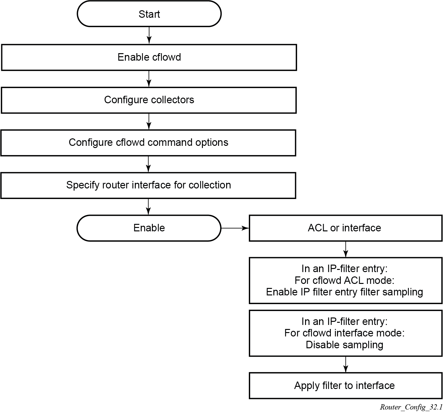
There are three modes in which cflowd can be enabled to sample traffic on an interface:
-
Cflowd interface – where all traffic entering a specified port is subjected to sampling at the configured sampling rate
-
Cflowd interface plus – the definition of IP filters that specify an action to disable sampling, where traffic that matches these filter entries is not subject to cflowd sampling
Use the following commands to disable sampling as part of the IP filter configuration:
-
MD-CLI
configure filter ip-filter entry interface-sample false configure filter ipv6-filter entry interface-sample false -
classic CLI
configure filter ip-filter entry interface-disable-sample
configure filter ipv6-filter entry interface-disable-sample
-
-
Cflowd ACL – where IP filters must be created with entries containing the action filter-sampled. In this mode, only traffic matching these filter entries is subject to the cflowd sampling process.
Configuration notes
The following cflowd components must be configured for cflowd to be operational:
Cflowd is enabled globally.
At least one collector must be configured and enabled.
A cflowd option must be specified and enabled on a router interface.
Sampling must be enabled on either:
An IP filter that is applied to a port or service.
An interface on a port or service.
Configuring cflowd with CLI
This section provides information to configure cflowd using the command line interface (CLI).
Cflowd configuration overview
SR OS implementation of cflowd supports the option to analyze traffic flow. The implementation also supports the use of traffic or access list (ACL) filters to limit the type of traffic that is analyzed.
Traffic sampling
Traffic sampling does not examine all packets received by a router. Command options allow the rate at which traffic is sampled and sent for flow analysis to be modified. The default sampling rate is every 1000th packet. Excessive sampling over an extended period of time, for example, more than every 1000th packet, can burden router processing resources.
The following data is maintained for each individual flow in the raw flow cache:
source IP address
destinations IP address
source port
destination port
forwarding status
input interface
output interface
IP protocol
TCP flags
first timestamp (of the first packet in the flow)
last timestamp (timestamp of last packet in the flow before the expiry of the flow)
source AS number for peer and origin (taken from BGP)
destination AS number for peer and origin (taken from BGP)
IP next hop
BGP next hop
ICMP type and code
IP version
source prefix (from routing)
destination prefix (from routing)
MPLS label stack from label 1 to 6
Within the raw flow cache, the following characteristics are used to identify an individual flow:
ingress interface
source IP address
destination IP address
source transport port number
destination transport port number
IP protocol type
IP ToS byte
virtual router ID
ICMP type and code
direction
MPLS labels
SR OS implementation allows cflowd to be enabled at the interface level or as an action to a filter. By enabling cflowd at the interface level, all IP packets forwarded by the interface are subject to cflowd analysis. By setting cflowd as an action in a filter, only packets matching the specified filter are subject to cflowd analysis. This provides the network user greater flexibility in the types of flows that are captured.
Collectors
A collector defines how data flows should be exported from the flow cache. A maximum of five collectors can be configured. Each collector is identified by a unique IP address and UDP port value. Each collector can only export traffic in one version type: V5, V8, V9, or V10.
The command options within a collector configuration can be modified or the defaults retained.
The autonomous-system-type command defines whether the autonomous system information to be included in the flow data is based on the originating AS or external peer AS of the flow.
Aggregation
V8 aggregation allows for flow data to be aggregated into larger, less granular flows. Use aggregation commands to specify the type of data to be collected. These aggregation types are only applicable to flows being exported to a V8 collector.
The following aggregation schemes are supported:
AS matrix
Flows are aggregated based on source and destination AS and ingress and egress interface.
protocol port
Flows are aggregated based on the IP protocol, source port number, and destination port number.
source prefix
Flows are aggregated based on source prefix and mask, source AS, and ingress interface.
destination prefix
Flows are aggregated based on destination prefix and mask, destination AS, and egress interface.
source-destination prefix
Flows are aggregated based on source prefix and mask, destination prefix and mask, source and destination AS, ingress interface, and egress interface.
raw
Flows are not aggregated and are sent to the collector in a V5 record.
Basic cflowd configuration
This section provides information to configure cflowd and examples of common configuration tasks. To sample traffic, the following command options must be configured, as a minimum.
Cflowd must be enabled.
At least one collector must be configured and enabled.
Sampling must be enabled on either:
an IP filter entry (and applied to a service or a port)
an interface applied to a port
The following example shows the cflowd configuration.
MD-CLI
[ex:/configure cflowd]
A:admin@node-2# info detail
## apply-groups
 ## apply-groups-exclude
    admin-state enable
    analyze-gre-payload false
    analyze-l2tp-traffic false
    analyze-v4overv6-traffic false
    cache-size 6553
    export-mode automatic
    inband-collector-export-only false
    overflow 1
    template-retransmit 600
    use-vrtr-if-index false
    active-flow-timeout 1800
    inactive-flow-timeout 15
    sample-profile 1 {
     ## apply-groups
     ## apply-groups-exclude
        sample-rate 1000
    }
classic CLI
A:node-2>config>cflowd# info detail
----------------------------------------------
        active-flow-timeout 1800
        cache-size 6553
        inactive-flow-timeout 15
        export-mode automatic
        overflow 1
        template-retransmit 600
        no use-vrtr-if-index
        no inband-collector-export-only
        no analyze-gre-payload
        no analyze-l2tp-traffic
        no analyze-v4overv6-traffic
        sample-profile 1 create
            sample-rate 1000
        exit
        no shutdown
----------------------------------------------
Common configuration tasks
This section provides a brief overview of the tasks that must be performed to configure cflowd and provides the CLI commands. To begin traffic flow sampling, cflowd must be enabled and at least one collector must be configured.
Global cflowd components
The following common (global) attributes apply to all instances of cflowd:
active flow timeout
The active flow timeout attribute controls the maximum time a flow record can be active before it is automatically exported to defined collectors.
inactive flow timeout
The inactive flow timeout attribute controls the minimum time before a flow is declared inactive. If no traffic is sampled for a flow for the inactive timeout duration, the flow is declared inactive and marked to be exported to the defined collectors.
cache size
The cache size attribute defines the maximum size of the flow cache.
overflow
The overflow attribute defines the percentage of flow records that are exported to all collectors if the flow cache size is exceeded.
rate
The rate attribute defines the system-wide sampling rate for cflowd.
template retransmit
The template retransmit attribute defines the interval (in seconds) at which the V9 and V10 templates are retransmitted to all configured V9 or V10 collectors.
Enabling cflowd
Cflowd is disabled by default. Cflowd must be configured with at least one collector to be active. Executing the cflowd command enables cflowd.
The following example shows the defaults when cflowd is initially enabled. No collectors or collector options are configured.
MD-CLI
[ex:/configure cflowd]
A:admin@node-2# info detail
...
    admin-state enable
...
    cache-size 65536
...
     overflow 1
...
    template-retransmit 600
...
    active-flow-timeout 1800
    inactive-flow-timeout 15
    sample-profile 1 {
...
        sample-rate 1000
    }
classic CLI
*A:node-2>config>cflowd# info detail
----------------------------------------------
        active-flow-timeout 1800
        cache-size 65536
        inactive-flow-timeout 15
...
        overflow 1
        template-retransmit 600
...
        sample-profile 1 create
            sample-rate 1000
        exit
        no shutdown
----------------------------------------------
Configuring global cflowd
The following example shows the global cflowd configuration.
MD-CLI
*[ex:/configure cflowd]
A:admin@node-2# info
...
    overflow 10
...
    active-flow-timeout 1800
    inactive-flow-timeout 10
    sample-profile 1 {
        sample-rate 100
    }
classic CLI
*A:node-2>config>cflowd# info detail
----------------------------------------------
        active-flow-timeout 1800
...
*A:node-2>config>cflowd# info
----------------------------------------------
        inactive-flow-timeout 10
...
        overflow 10
        sample-profile 1 create
            sample-rate 100
        exit
----------------------------------------------
Configuring cflowd collectors
The following example shows a basic configuration of cflowd collectors.
Basic cflowd collector configuration (MD-CLI)
*[ex:/configure cflowd]
A:admin@node-2# info
...
    overflow 10
...
    active-flow-timeout 1800
    inactive-flow-timeout 10
    sample-profile 1 {
        sample-rate 100
    }
    collector 10.10.10.1 port 2000 {
        description "AS info collector"
        version 8
        aggregation {
            as-matrix true
            raw true
        }
    }
 collector 10.10.10.2 port 5000 {
        description "Neighbor collector"
        autonomous-system-type peer
        version 8
        aggregation {
            protocol-port true
            source-destination-prefix true
        }
    }
Basic cflowd collector configuration (classic CLI)
*A:node-2>config>cflowd# info detail
----------------------------------------------
        active-flow-timeout 1800
...
A:node-2>config>cflowd# info
-----------------------------------------
        inactive-flow-timeout 10
        overflow 10
        sample-profile 1 create
            sample-rate 100
        exit
        collector 10.10.10.1:2000 version 8
            description "AS info collector"
            aggregation
                as-matrix
                raw
            exit
        exit
        collector 10.10.10.2:5000 version 8
            description "Neighbor collector"
            aggregation
                protocol-port
                source-destination-prefix
            exit
            autonomous-system-type peer
        exit
Version 9 collector configuration (MD-CLI)
*[ex:/configure cflowd]
A:admin@node-2# info
...
    collector 10.10.10.9 port 2000 {
        description "v9collector"
        template-set mpls-ip
        version 9
    }
Version 9 collector configuration (classic CLI)
*A:node-2>config>cflowd# info
----------------------------------------------
...
        collector 10.10.10.9:2000 version 9
            description "v9collector"
            template-set mpls-ip
        exit
----------------------------------------------
Version 9 and Version 10 templates
If the collector is configured to use either V9 or V10 (IPFIX) formats, the flow data is sent to the designated collector using one of the predefined templates. The template used is based on the type of flow for which the data was collected (IPv4, IPv6, MPLS, or Ethernet [Layer 2]), and the configuration of the template-set command. The following table lists these options and the corresponding template used to export the flow data.
| Traffic flow | Basic | MPLS-IP |
|---|---|---|
|
IPv4 |
Basic IPv4 |
MPLS-IPv4 |
|
IPv6 |
Basic IPv6 |
MPLS-IPv6 |
|
MPLS |
Basic MPLS |
MPLS-IP |
|
Ethernet |
L2-IP |
L2-IP |
Each flow exported to a collector configured for either V9 or V10 formats is sent using one of the flow template sets listed in Template sets.
Basic IPv4 template to MPLS transport template list the fields in each template listed in Template sets.
| Field name | Field ID |
|---|---|
|
IPv4 Src Addr |
8 |
|
IPv4 Dest Addr |
12 |
|
IPv4 Nexthop |
15 |
|
BGP Nexthop |
18 |
|
Ingress Interface |
10 |
|
Egress Interface |
14 |
|
Packet Count |
2 |
|
Byte Count |
1 |
|
Start Time |
22 |
|
End Time |
21 |
| Flow Start Milliseconds1 |
152 |
| Flow End Milliseconds1 |
153 |
|
Src Port |
7 |
|
Dest Port |
11 |
|
Forwarding Status |
89 |
|
TCP control Bits (Flags) |
6 |
|
IPv4 Protocol |
4 |
|
IPv4 ToS |
5 |
|
IP version |
60 |
|
ICMP Type and Code |
32 |
|
Direction |
61 |
|
BGP Source ASN |
16 |
|
BGP Dest ASN |
17 |
|
Source IPv4 Prefix Length |
9 |
|
Dest IPv4 Prefix Length |
13 |
|
Minimum IP Total Length |
25 |
|
Maximum IP Total Length |
26 |
|
Minimum TTL |
52 |
|
Maximum TTL |
53 |
|
Multicast Replication Factor |
99 |
|
bgpNextAdjacentAsNumber |
128 |
|
bgpPrevAdjacentAsNumber |
129 |
| IsMulticast1 |
206 |
| Ingress VRFID1 |
234 |
| Egress VRFID1 |
235 |
| Field Name | Field ID |
|---|---|
|
IPv4 Src Addr |
8 |
|
IPv4 Dest Addr |
12 |
|
IPv4 Nexthop |
15 |
|
BGP Nexthop |
18 |
|
Ingress Interface |
10 |
|
Egress Interface |
14 |
|
Packet Count |
2 |
|
Byte Count |
1 |
|
Start Time |
22 |
|
End Time |
21 |
| Flow Start Milliseconds1 |
152 |
|
Flow End Milliseconds1 |
153 |
|
Src Port |
7 |
|
Dest Port |
11 |
|
Forwarding Status |
89 |
|
TCP control Bits (Flags) |
6 |
|
IPv4 Protocol |
4 |
|
IPv4 ToS |
5 |
|
IP version |
60 |
|
ICMP Type & Code |
32 |
|
Direction |
61 |
|
BGP Source ASN |
16 |
|
BGP Dest ASN |
17 |
|
Source IPv4 Prefix Length |
9 |
|
Dest IPv4 Prefix Length |
13 |
|
MPLS Top Label Type |
46 |
|
MPLS Top Label IPv4 Addr |
47 |
|
MPLS Label 1 |
70 |
|
MPLS Label 2 |
71 |
|
MPLS Label 3 |
72 |
|
MPLS Label 4 |
73 |
|
MPLS Label 5 |
74 |
|
MPLS Label 6 |
75 |
|
MPLS Label 7 |
76 |
|
MPLS Label 8 |
77 |
|
MPLS Label 9 |
78 |
|
MPLS Label 10 |
79 |
|
Minimum IP Total Length |
25 |
|
Maximum IP Total Length |
26 |
|
Minimum TTL |
52 |
|
Maximum TTL |
53 |
|
Multicast Replication Factor |
99 |
|
bgpNextAdjacentAsNumber |
128 |
|
bgpPrevAdjacentAsNumber |
129 |
| IsMulticast1 |
206 |
| Ingress VRFID1 |
234 |
| Egress VRFID1 |
235 |
| Field Name |
Field ID |
|---|---|
|
IPv6 Src Addr |
27 |
|
IPv6 Dest Addr |
28 |
|
IPv6 Nexthop |
62 |
|
IPv6 BGP Nexthop |
63 |
|
IPv4 Nexthop |
15 |
|
IPv4 BGP Nexthop |
18 |
|
Ingress Interface |
10 |
|
Egress Interface |
14 |
|
Packet Count |
2 |
|
Byte Count |
1 |
|
Start Time |
22 |
|
End Time |
21 |
| Flow Start Milliseconds1 |
152 |
| Flow End Milliseconds1 |
153 |
|
Src Port |
7 |
|
Dest Port |
11 |
|
Forwarding Status |
89 |
|
TCP control Bits (Flags) |
6 |
|
Protocol |
4 |
|
IPv6 Extension Hdr |
64 |
|
IPv6 Next Header |
193 |
|
IPv6 Flow Label |
31 |
|
ToS |
5 |
|
IP version |
60 |
|
IPv6 ICMP Type & Code |
139 |
|
Direction |
61 |
|
BGP Source ASN |
16 |
|
BGP Dest ASN |
17 |
|
IPv6 Src Mask |
29 |
|
IPv6 Dest Mask |
30 |
|
Minimum IP Total Length |
25 |
|
Maximum IP Total Length |
26 |
|
Minimum TTL |
52 |
|
Maximum TTL |
53 |
|
Multicast Replication Factor |
99 |
|
bgpNextAdjacentAsNumber |
128 |
|
bgpPrevAdjacentAsNumber |
129 |
| IsMulticast1 |
206 |
| Ingress VRFID1 |
234 |
| Egress VRFID1 |
235 |
| Field name | Field ID |
|---|---|
|
IPv6 Src Addr |
27 |
|
IPv6 Dest Addr |
28 |
|
IPv6 Nexthop |
62 |
|
IPv6 BGP Nexthop |
63 |
|
IPv4 Nexthop |
15 |
|
IPv4 BGP Nexthop |
18 |
|
Ingress Interface |
10 |
|
Egress Interface |
14 |
|
Packet Count |
2 |
|
Byte Count |
1 |
|
Start Time |
22 |
|
End Time |
21 |
| Flow Start Milliseconds1 |
152 |
| Flow End Milliseconds1 |
153 |
|
Src Port |
7 |
|
Dest Port |
11 |
|
Forwarding Status |
89 |
|
TCP control Bits (Flags) |
6 |
|
Protocol |
4 |
|
IPv6 Extension Hdr |
64 |
|
IPv6 Next Header |
193 |
|
IPv6 Flow Label |
31 |
|
ToS |
5 |
|
IP version |
60 |
|
IPv6 ICMP Type & Code |
139 |
|
Direction |
61 |
|
BGP Source ASN |
16 |
|
BGP Dest ASN |
17 |
|
IPv6 Src Mask |
29 |
|
IPv6 Dest Mask |
30 |
|
MPLS Top Label Type |
46 |
|
MPLS Top Label IPv6 Addr |
47 |
|
MPLS Label 1 |
70 |
|
MPLS Label 2 |
71 |
|
MPLS Label 3 |
72 |
|
MPLS Label 4 |
73 |
|
MPLS Label 5 |
74 |
|
MPLS Label 6 |
75 |
|
MPLS Label 7 |
76 |
|
MPLS Label 8 |
77 |
|
MPLS Label 9 |
78 |
|
MPLS Label 10 |
79 |
|
MPLS_TOP_LABEL_TYPE |
46 |
|
MPLS_TOP_LABEL_ADDR |
47 |
|
Minimum IP Total Length |
25 |
|
Maximum IP Total Length |
26 |
|
Minimum TTL |
52 |
|
Maximum TTL |
53 |
|
Multicast Replication Factor |
99 |
|
bgpNextAdjacentAsNumber |
128 |
|
bgpPrevAdjacentAsNumber |
129 |
| IsMulticast1 |
206 |
| Ingress VRFID1 |
234 |
| Egress VRFID1 |
235 |
| Field name | Field ID |
|---|---|
|
Start Time |
22 |
|
End Time |
21 |
| Flow Start Milliseconds1 |
152 |
| Flow End Milliseconds1 |
153 |
|
Ingress Interface |
10 |
|
Egress Interface |
14 |
|
Packet Count |
2 |
|
Byte Count |
1 |
|
Direction |
61 |
|
MPLS Top Label Type |
46 |
|
MPLS Top Label Address |
47 |
|
MPLS Label 1 |
70 |
|
MPLS Label 2 |
71 |
|
MPLS Label 3 |
72 |
|
MPLS Label 4 |
73 |
|
MPLS Label 5 |
74 |
|
MPLS Label 6 |
75 |
| Field name | Field ID |
|---|---|
|
IPv4 Src Addr |
8 |
|
IPv4 Dest Addr |
12 |
|
IPv4 Nexthop |
15 |
|
IPv6 Src Addr |
27 |
|
IPv6 Dest Addr |
28 |
|
IPv6 Nexthop |
62 |
|
Ingress Interface |
10 |
|
Egress Interface |
14 |
|
Packet Count |
2 |
|
Byte Count |
1 |
|
Start Time |
22 |
|
End Time |
21 |
| Flow Start Milliseconds1 |
152 |
| Flow End Milliseconds1 |
153 |
|
Src Port |
7 |
|
Dest Port |
11 |
|
TCP control Bits (Flags) |
6 |
|
IPv4 Protocol |
4 |
|
IPv4 ToS |
5 |
|
IP version |
60 |
|
ICMP Type & Code |
32 |
|
IPv6 Flow Label |
31 |
|
Direction |
61 |
|
MPLS Top Label Type |
46 |
|
MPLS Top Label IPv4 Addr |
47 |
|
MPLS Label 1 |
70 |
|
MPLS Label 2 |
71 |
|
MPLS Label 3 |
72 |
|
MPLS Label 4 |
73 |
|
MPLS Label 5 |
74 |
|
MPLS Label 6 |
75 |
|
MPLS Label 7 |
76 |
|
MPLS Label 8 |
77 |
|
MPLS Label 9 |
78 |
|
MPLS Label 10 |
79 |
To address L2-IP (Ethernet) flow template, only one Ethernet (L2-IP) flow template is supported and exported to IPFIX (V10) collectors.
| Field name |
Field ID |
|---|---|
|
MAC Src Addr |
56 |
|
MAC Dest Addr |
80 |
|
Ingress Physical Interface |
252 |
|
Egress Physical Interface |
253 |
|
Dot1q VLAN ID |
243 |
|
Dot1q Customer VLAN ID |
245 |
|
Post Dot1q VLAN ID |
254 |
|
Post Dot1q Customer VLAN Id |
255 |
|
IPv4 Src Addr |
8 |
|
IPv4 Dest Addr |
12 |
|
IPv6 Src Addr |
27 |
|
IPv6 Dest Addr |
28 |
|
Packet Count |
2 |
|
Byte Count |
1 |
|
Flow Start Milliseconds |
152 |
|
Flow End Milliseconds |
153 |
|
Src Port |
7 |
|
Dest Port |
11 |
|
TCP control Bits (Flags) |
6 |
|
Protocol |
4 |
|
IPv6 Option Header |
64 |
|
IPv6 Next Header |
196 |
|
IPv6 Flow Label |
31 |
|
ToS |
5 |
|
IP Version |
60 |
|
ICMP Type Code |
32 |
|
Ingress VRF |
234 |
|
IPv4 BGP Nexthop |
18 |
|
IPv6 BGP Nexthop |
63 |
| Field name | Field ID |
|---|---|
|
Flow Start Milliseconds |
152 |
|
Flow End Milliseconds |
153 |
|
VRF ID |
234 |
|
Ingress Interface |
10 |
|
Packet Count |
2 |
|
Byte Count |
1 |
|
Direction |
61 |
|
MPLS_TOP_LABEL_TYPE |
46 |
|
MPLS_TOP_LABEL_ADDR |
47 |
|
MPLS Label-1 |
70 |
Specifying cflowd on an IP interface
When cflowd is enabled on an interface, all packets forwarded by the interface are subject to analysis according to the global cflowd configuration and sorted according to the collector configurations.
See Cflowd configuration dependencies for configuration combinations.
Use the following command to configure cflowd on an IP interface.
configure router interface cflowd-parameters sampling unicast type interfaceWhen the preceding command is configured, the following requirements must be met to enable traffic sampling on the interface:
Enable cflowd.
Ensure at least one cflowd collector is configured and enabled.
-
Use the commands in the following context to configure sampling as unicast or multicast, as well as the type and direction of the sampling. By default, the direction is ingress-only.
configure router interface cflowd-parameters sampling - Use the following commands to prevent specific types of traffic from
being sampled when interface sampling is enabled. The filter must be applied to the
service or network interface on which the traffic to be omitted is to ingress the
system.
-
MD-CLI
configure filter ip-filter entry interface-sample false configure filter ipv6-filter entry interface-sample false -
classic CLI
configure filter ip-filter entry interface-disable-sample
configure filter ipv6-filter entry interface-disable-sample
-
Interface sampling configuration
Use the commands in the following context to configure cflowd sampling on an interface.
configure router interface cflowd-parameters samplingDepending on the sampling type command option selected, either acl or interface, cflowd extracts traffic flow samples from an IP filter or an interface for analysis. All packets forwarded by the interface are analyzed according to the cflowd configuration.
-
MD-CLI
configure filter ip-filter entry filter-sample true -
classic CLI
configure filter ip-filter entry filter-sample
The interface command option must be selected to enable traffic sampling on an interface. If cflowd is not enabled, traffic sampling does not occur on the interface.
Service interfaces
Use the commands in the following context to configure cflowd on a service interface.
configure router interface cflowd-parameters samplingWhen enabled on a service interface, cflowd collects routed traffic flow samples through a router for analysis. Cflowd is supported on IES and VPRN service interfaces only. Layer 2 traffic is excluded. All packets forwarded by the interface are analyzed according to the cflowd configuration. On the interface level, cflowd can be associated with a filter (ACL) or an IP interface. Layer 2 cflowd ingress sampling is supported on VPLS and Epipe SAPs.
Compact templates
| IPFIX Field | Field ID |
|---|---|
Packet |
2 |
Byte |
1 |
Input ifIndex |
10 |
Output ifIndex |
14 |
IP version |
60 |
IP Src Port |
7 |
IP Dst Port |
11 |
IP proto |
4 |
IP tcpflags |
6 |
Flow Start |
22/152 |
Flow Stop |
21/153 |
IP min TTL |
52 |
IP max TTL |
53 |
IP tos |
5 |
Flow Direction |
61 |
IP icmp type/code |
32 |
Forwarding status |
89 |
IP src Address |
8 (IPv4) |
IP dst Address |
12 (IPv4) |
| IPFIX Field | Field ID |
|---|---|
Packet |
2 |
Byte |
1 |
Input ifIndex |
10 |
Output ifIndex |
14 |
IP version |
60 |
IP Src Port |
7 |
IP Dst Port |
11 |
IP proto |
4 |
IP tcpflags |
6 |
Flow Start |
22/152 |
Flow Stop |
21/153 |
IP min TTL |
52 |
IP max TTL |
53 |
IP tos |
5 |
Flow Direction |
61 |
IPv6 ICMP type/code |
139 |
Forwarding status |
89 |
IP src Address |
27(IPv6) |
IP dst Address |
28(IPv6) |
| IPFIX Field | Field ID |
|---|---|
Flow Start |
22/152 |
Flow Stop |
21/153 |
Input ifIndex |
10 |
Output ifIndex |
14 |
Packet |
2 |
Byte |
1 |
Flow Direction |
61 |
MPLS Top Label |
46 |
MPLS Top Label IPv4 Address |
47 |
MPLS Label 1 |
70 |
MPLS Label 2 |
71 |
MPLS Label 3 |
72 |
MPLS Label 4 |
73 |
MPLS Label 5 |
74 |
MPLS Label 6 |
75 |
MPLS Label 7 |
76 |
MPLS Label 8 |
77 |
MPLS Label 9 |
78 |
MPLS Label 10 |
79 |
| IPFIX Field | Field ID |
|---|---|
Source MAC Address |
53 |
Destination MAC Address |
80 |
Ingress Physical Interface |
252 |
Egress Physical Interface |
253 |
Dot1q VLAN ID |
243 |
Dot1q Customer VLAN ID |
245 |
Post Dot1q VLAN ID |
254 |
Post Dot1q Customer VLAN ID |
255 |
IPv4 src Address |
8 |
IPv4 dst Address |
12 |
IPv6 src Address |
27 |
IPv6 dst Address |
28 |
Packet Count |
2 |
Byte Count |
1 |
Flow Start Millisecond |
152 |
Flow End Millisecond |
153 |
FP-accelerated templates
| IPFIX Field | Field ID |
|---|---|
Byte |
1 |
Input ifIndex |
10 |
Output ifIndex |
14 |
IP version |
60 |
IP src Port |
7 |
IP Dst Port |
11 |
IP Proto |
4 |
IP TCP flags |
6 |
IP min TTL |
52 |
IP TOS |
5 |
IP icmp type/code |
32 |
Forwarding status |
89 |
IP src Address1 |
8 (IPv4) |
IP dst Address1 |
12 (IPv4) |
| IPFIX Field | Field ID |
|---|---|
Byte |
1 |
Input ifIndex |
10 |
Output ifIndex |
14 |
IP version |
60 |
IP src Port |
7 |
IP Dst Port |
11 |
IP Proto |
4 |
IP TCP flags |
6 |
IP min TTL |
52 |
IP TOS |
5 |
Forwarding status |
89 |
IP src Address1 |
27(IPv6) |
IP dst Address1 |
28(IPv6) |
Specifying sampling options in filter entries
Packets are matched against filter entries to determine acceptability. With cflowd, only the first packet of a flow is compared. If the first packet matches the filter criteria, an entry is added to the cflowd cache. Subsequent packets in the same flow are also sampled based on the cache entry.
Because a filter can be applied to more than one interface (when configured with a scope template), you can enable or disable traffic sampling on an interface-by-interface basis. Use the following command to disable traffic sampling:
-
MD-CLI
configure filter ip-filter entry interface-sample false -
classic CLI
configure filter ip-filter entry interface-disable-sample
The preceding command to disable traffic sampling can be enabled or disabled as needed instead of having to create numerous filter versions.
To enable an interface for filter traffic sampling, the following requirements must be met:
Cflowd must be enabled globally.
At least one cflowd collector must be configured and enabled.
-
Use the commands in the following context on the IP interface that is used to configure sampling as unicast or multicast. You must also select the ACL option.
configure router interface cflowd-parameters sampling - On the IP filter being used, you must explicitly enable filter sampling for the entries matching the traffic that should be sampled. Use the following commands to configure filter sampling for the filter:
-
MD-CLI
configure filter ip-filter entry filter-sample true configure filter ipv6-filter entry filter-sample true -
classic CLI
configure filter ip-filter entry filter-sample
configure filter ipv6-filter entry filter-sample
The default is disabled. See Filter configurations for more information.
-
The filter must be applied to a service or a network interface. The service or port must be enabled and operational.
Filter configurations
-
MD-CLI
configure filter ip-filter entry filter-sample true -
classic CLI
configure filter ip-filter entry filter-sample
When the traffic sampling is disabled, traffic matching the associated IP filter entry is not sampled if the IP interface is set to cflowd ACL mode. Use the following command to disable traffic sampling:
-
MD-CLI
configure filter ip-filter entry interface-sample false -
classic CLI
configure filter ip-filter entry interface-disable-sample
Dependencies
For cflowd to be operational, the following requirements must be met:
Cflowd must be enabled on a global level. If cflowd is disabled, any traffic sampling instances are also disabled.
At least one collector must be configured and enabled in order for traffic sampling to occur on an enabled entity.
If a specific collector UDP port is not identified, flows are sent to port 2055 by default.
Cflowd can also be dependent on the following entity configurations:
The combination of interface and filter entry configurations determines whether flow sampling occurs. Cflowd configuration dependencies lists the expected results based on cflowd configuration dependencies.
| Interface Setting | cflowd-parameter type Setting | Command ip-filter entry Setting | Expected Results |
|---|---|---|---|
|
IP-filter mode |
ACL |
filter-sample true (MD-CLI) filter-sample (classic CLI) |
Traffic matching is sampled at specified rate |
|
IP-filter mode |
ACL |
filter-sample false (MD-CLI) no filter-sample (classic CLI) |
No traffic is sampled on this interface |
|
IP-filter mode or cflowd not enabled on interface |
ACL |
interface-sample false (MD-CLI) interface-disable-sample (classic CLI) |
Command is ignored; no sampling occurs |
|
Interface mode |
Interface |
interface-sample false (MD-CLI) interface-disable-sample (classic CLI) |
Traffic matching this IP filter entry is not sampled |
|
Interface mode |
Interface |
none |
All IP traffic ingressing the interface is subject to sampling |
|
Interface mode |
Interface |
filter-sample true (MD-CLI) filter-sample (classic CLI) |
Filter-level action is ignored; all traffic ingressing the interface is subject to sampling |
Cflowd configuration management tasks
This section describes cflowd configuration management tasks.
Modifying global cflowd
Cflowd modifications apply to all instances where cflowd is enabled. Use the commands in the following context to configure cflowd.
configure cflowdModification of a cflowd configuration (MD-CLI)
*[ex:/configure cflowd]
A:admin@node-2# active-flow-timeout 3600

*[ex:/configure cflowd]
A:admin@node-2# inactive-flow-timeout 15

*[ex:/configure cflowd]
A:admin@node-2# overflow 2

*[ex:/configure cflowd]
A:admin@node-2# sample-profile 1

*[ex:/configure cflowd sample-profile 1]
A:admin@node-2# sample-rate 10
Cflowd configuration output (MD-CLI)
*[ex:/configure cflowd]
A:admin@node-2# info detail
...
    inactive-flow-timeout 15
...
*[ex:/configure cflowd]
A:admin@node-2# info
...
    overflow 2
...
    active-flow-timeout 3600
    sample-profile 1 {
        sample-rate 10
    }
...
   }
Modification of a cflowd configuration (classic CLI)
*A:node-2>config>cflowd# active-flow-timeout 3600
*A:node-2>config>cflowd# inactive-flow-timeout 15
*A:node-2>config>cflowd# overflow 2
*A:node-2>config>cflowd# sample-profile 1 create
*A:node-2>config>cflowd>sample-profile# sample-rate 10
Cflowd configuration output (classic CLI)
*A:node-2>config>cflowd# info detail
----------------------------------------------
 ...
        inactive-flow-timeout 15
...
*A:node-2>config>cflowd# info
----------------------------------------------
        active-flow-timeout 3600
...
        overflow 2
        sample-profile 1 create
            sample-rate 10
        exit
Modifying cflowd collector command options
Use the commands in the following context to modify cflowd collector and aggregation command options.
configure cflowdIf a specific collector UDP port is not identified, flows are sent to port 2055 by default.
The following example shows a basic cflowd configuration that has been modified.
MD-CLI
*[ex:/configure cflowd]
A:admin@node-2# info
...
    overflow 2
...
    active-flow-timeout 3600
    sample-profile 1 {
        sample-rate 10
    }
    collector 10.10.10.1 port 2000 {
        description "AS info collector"
        version 8
        }
    }
    collector 10.10.10.2 port 5000 {
        description "Test collector"
        version 9
        aggregation {
            source-prefix true
            raw true
        }
    }
classic CLI
A:node-2>config>cflowd# info
-----------------------------------------
     active-flow-timeout 3600
        overflow 2
        sample-profile 1 create
            sample-rate 10
        exit
        collector 10.10.10.1:2000 version 8
            description "AS info collector"
        exit
        collector 10.10.10.2:5000 version 9
            description "Test collector"
            aggregation
                source-prefix
                raw
            exit
        exit
-----------------------------------------
FP acceleration for cflowd processing
FP acceleration for cflowd allows the FP complex on specific CPMs to process and directly export IPv4 and IPv6 flow records. This feature supports significantly higher sampling capacity and flow record generation. The feature requires using CPM-2 or later in 7750 SR-7s and SR-14s, and 7950 XRS. When enabled, cflowd samples from configured interfaces are sent to the FP complex located on the CPM, which then pulls specific information from the IPv4 or IPv6 headers to populate the FP, accelerated flow record template. This mechanism generates a flow record for each sample.
Configuring FP acceleration for cflowd processing
To enable FP-accelerated cflowd processing, configure the following:
-
Use the following command to configure a cflowd collector for FP-accelerated cflowd processing.
configure cflowd collector template-set fastpath -
Use the following command to configure one or more sample profiles.
configure cflowd sample-profile metering-process fp-accelerated
The following example shows the configuration of FP acceleration for cflowd processing.
MD-CLI
[ex:/configure]
A:admin@node-2# info
    cflowd {
        admin-state enable
...
        inband-collector-export-only true
...
        sample-profile 2 {
            sample-rate 2000
            metering-process fp-accelerated
        }
        collector 10.10.10.10 port 1 {
            template-set fastpath
            version 10
        }
    }
Supported forwarding status codes
The following table shows supported forwarding status codes.
| Status | Reported code (field 89) |
|---|---|
Forwarded |
64 |
Drop-ACL |
130 |
Drop-Unroutable |
131 |
Drop-Fragmentation needed but DF bit set |
133 |
Drop-uRPF failure |
140 |