VRRP
VRRP overview
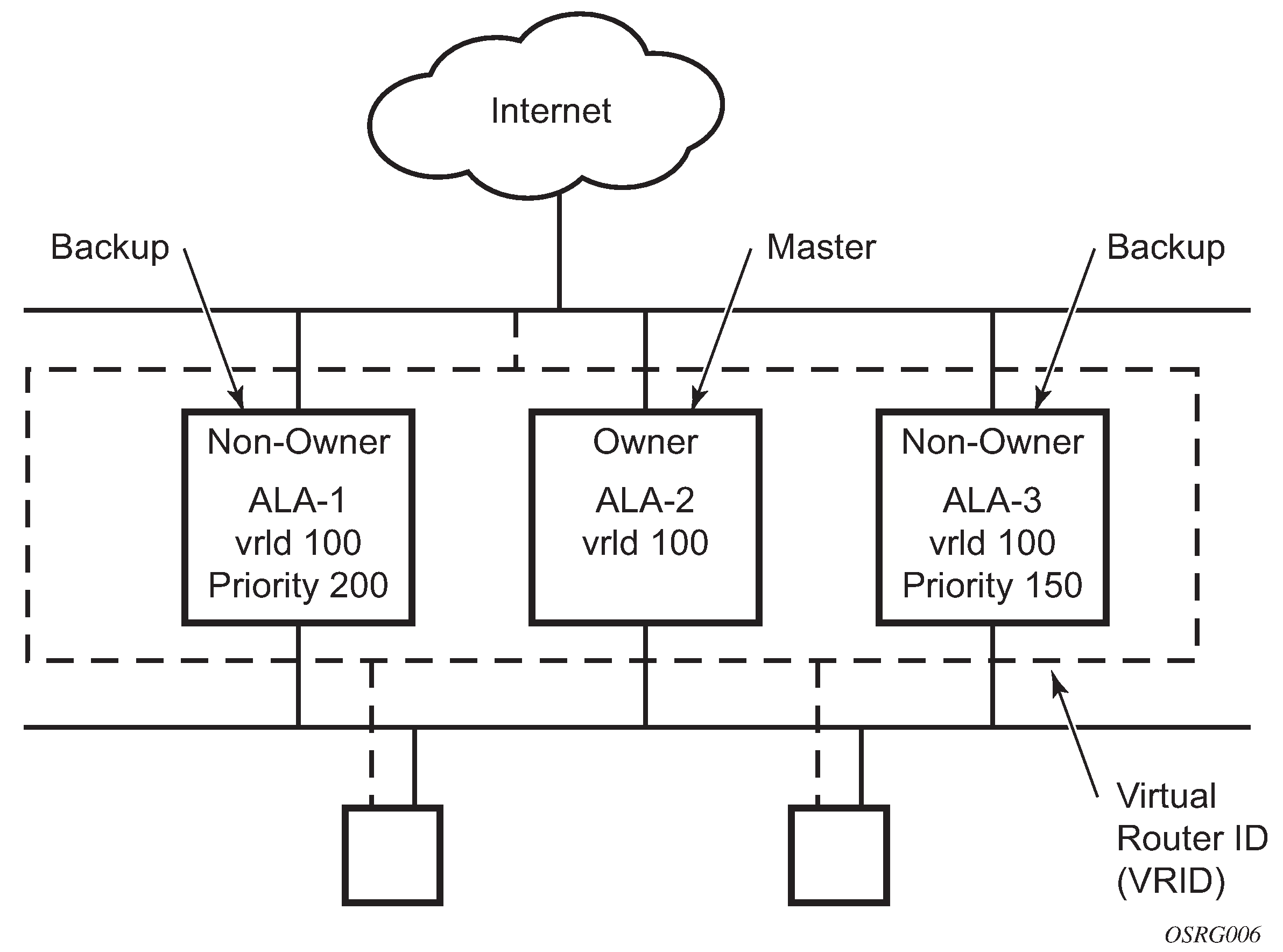
The Virtual Router Redundancy Protocol (VRRP) for IPv4 is defined in the IETF RFC 3768, Virtual Router Redundancy Protocol. VRRP for IPv6 is specified in draft-ietf-vrrp-unified-spec-02.txt and only applies to the 7750 SR and 7950 XRS. VRRP describes a method of implementing a redundant IP interface shared between two or more routers on a common LAN segment, allowing a group of routers to function as one virtual router. When this IP interface is specified as a default gateway on hosts directly attached to this LAN, the routers sharing the IP interface prevent a single point of failure by limiting access to this gateway address. VRRP can be implemented on IES service interfaces and on core network IP interfaces.
The VRRP standard RFC 3768 uses the term ‟master” state to denote the virtual router that is currently acting as the active forwarding router for the VRRP instance. This guide uses the term "active" as much as possible.
If the virtual router in master state fails, the backup router configured with the highest acceptable priority becomes the active virtual router. The new active router assumes the normal packet forwarding for the local hosts.
VRRP Configuration shows an example of a VRRP configuration.
VRRP components
VRRP consists of the following components:
Virtual router
A virtual router is a logical entity managed by VRRP that acts as a default router for hosts on a shared LAN. It consists of a Virtual Router Identifier (VRID) and a set of associated IP addresses (or an address) across a common LAN. A VRRP router can be the backup for one or more virtual routers.
The purpose of supporting multiple IP addresses within a single virtual router is for multi-netting. This is a common mechanism that allows multiple local subnet attachments on a single routing interface. Up to four virtual routers are possible on a single Nokia IP interface. The virtual routers must be in the same subnet. Each virtual router has its own VRID, state machine, and messaging instance.
IP address owner
VRRP can be configured in either an owner or non-owner mode. The owner is the VRRP router whose virtual router IP address is the same as the real interface IP address. This is the router that responds to packets addressed to one of the IP addresses for ICMP pings, TCP connections, and so on. All other virtual router instances participating in this message domain must have the same VRID configured and cannot be configured as owner.
Nokia routers allow the virtual routers to be configured as non-owners of the IP address. VRRP on a router can be configured to allow non-owners to respond to ICMP echo requests when they become the virtual router in master state for the VRRP instance. Telnet and other connection-oriented protocols can also be configured for master. However, the individual application conversations (connections) do not survive a VRRP failover. A non-owner VRRP router operating as a backup does not respond to any packets addressed to any of the virtual router IP addresses.
Primary and secondary IP addresses
A primary address is an IP address selected from the set of real interface address. VRRP advertisements are always sent using the primary IP address as the source of the IP packet.
An IP interface must always have a primary IP address assigned for VRRP to be active on the interface. Nokia routers supports both primary and secondary IP addresses (multi-netting) on the IP interface. The virtual router’s VRID primary IP address is always the primary address on the IP interface. VRRP uses the primary IP address as the IP address placed in the source IP address field of the IP header for all VRRP messages sent on that interface.
Virtual router
The VRRP router that controls the IP addresses associated with a virtual router is considered to be in the master state and is the active router for the VRRP instance and is responsible for forwarding packets sent to the VRRP IP address. The election process provides dynamic failover of the forwarding responsibility if the master becomes unavailable. This allows any of the virtual router IP addresses on the LAN to be used as the default first hop router by end hosts. This enables a higher availability default path without requiring configuration of dynamic routing or router discovery protocols on every end host.
If the master is unavailable, each backup virtual router for the VRID compares the configured priority values to determine the master role. In case of a tie, the virtual router with the highest primary IP address becomes master.
The preempt command option can be set to false to prevent a backup virtual router with a better priority value from becoming master when an existing non-owner virtual router is the current master. This is determined on a first-come, first-served basis.
While master, a virtual router routes and originates all IP packets into the LAN using the physical MAC address for the IP interface as the Layer 2 source MAC address, not the VRID MAC address. ARP packets also use the parent IP interface MAC address as the Layer 2 source MAC address while inserting the virtual router MAC address in the appropriate hardware address field. VRRP messages are the only packets transmitted using the virtual router MAC address as the Layer 2 source MAC address.
Virtual router backup
A new virtual router master is selected from the set of VRRP routers available to assume forwarding responsibility for a virtual router in case the current master fails.
Owner and non-owner VRRP
The owner controls the IP address of the virtual router and is responsible for forwarding packets sent to this IP address. The owner assumes the role of the master virtual router. Only one virtual router in the domain can be configured as owner. All other virtual router instances participating in this message domain must have the same VRID configured.
The most important command option to be defined on a non-owner virtual router instance is the priority. The priority defines a virtual router’s selection order in the master election process. The priority value and the preempt mode determine the virtual router with the highest priority to become the master virtual router.
The base priority is used to determine the in-use priority of the virtual router instance as modified by any optional VRRP priority control policy. VRRP priority control policies can be used to either override or adjust the base priority value depending on events or conditions within the chassis.
For information about non-owner access command options, see VRRP non-owner accessibility.
For owner virtual router instances, use the following commands to define the IP addresses that are advertised within VRRP advertisement messages:
-
MD-CLI
configure router interface ipv4 vrrp backup configure router interface ipv6 vrrp backup -
classic CLI
configure router interface vrrp backup
configure router interface ipv6 vrrp backup
For owner virtual router instances, after you define the IP addresses that are advertised within VRRP advertisement messages, this communicates the IP addresses that the master is advertising to backup virtual routers receiving the messages. The specified unicast IPv4 address must be equal to one of the existing IP addresses in the parental IP interface (primary or secondary) or the backup command fails.
For non-owner virtual router instances, the backup command for IPv4 or IPv6 creates an IP interface IP address used for routing IP packets and communicating with the system, based on which access command options are enabled (ntp-reply, ping-reply, telnet-reply, and ssh-reply). The specified unicast IPv4 address must exist on one of the local subnets of the parental IP interface. If the specified address does not exist on one of the local subnets of the parental IP interface or if the specified address uses the same IP address as the parental IP interface, the backup command fails.
The backup command must be executed successfully at least once before the virtual router instance can enter the operational state.
The new interface IP address created with the backup command assumes the mask and command options of the corresponding parent IP interface IP address. The unicast IPv4 address is only active when the virtual router instance is operating in the master state. When not operating as master, the virtual router instance acts as if it is operationally down. It does not respond to ARP requests made to the unicast IPv4 address, nor does it route packets received with its VRID-derived source MAC address. A non-master virtual router instance always silently discards packets destined for the unicast IPv4 address. One virtual router instance may only have one virtual router IP address from a parental local subnet. Multiple virtual router instances can define a virtual router IP address from the same local subnet, as long as each IP address is different.
Configurable command options
As well as to backup IP addresses, to facilitate configuration of a virtual router on Nokia routers, the following command options can be defined in owner configurations:
The following command options can be defined in non-owner configurations:
Virtual Router ID (VRID)
The VRID must be configured with the same value on each virtual router associated with the redundant IP address (or addresses). The VRID is placed in all VRRP advertisement messages sent by each virtual router.
Priority
The priority value affects the interaction between this VRID and the same VRID of other virtual routers participating on the same LAN. A higher-priority value defines a greater priority in becoming the virtual router master for the VRID. The priority value can only be configured when the defined IP address on the IP interface is different from the virtual router IP address (non-owner mode).
When the IP address on the IP interface matches the virtual router IP address (owner mode), the priority value is fixed at 255, the highest value possible. This virtual router member is considered the owner of the virtual router IP address. There can only be one owner of the virtual router IP address for all virtual router members.
The priority value 0 is reserved for VRRP advertisement message purposes. It is used to tell other virtual routers in the same VRID that this virtual router is no longer acting as master, triggering a new election process. When this happens, each backup virtual router sets its master down timer equal to the skew time value. This shortens the time until one of the backup virtual routers becomes master.
The current master virtual router must transmit a VRRP advertisement message immediately upon receipt of a VRRP message with priority set to 0. This prevents another backup from becoming master for a short period of time.
Non-owner virtual routers may be configured with a priority of 254 through 1. The default value is 100. Multiple non-owners can share the same priority value. When multiple non-owner backup virtual routers are tied (transmit VRRP advertisement messages simultaneously) in the election process, all attempts to become master simultaneously. The one with the best priority wins the election. If the priority value in the message is equal to the master’s local priority value, the primary IP address of the local master and of the message is evaluated as the tie breaker. The higher IP address becomes master. (The primary IP address is the source IP address of the VRRP advertisement message.)
The priority value is also used to determine when to preempt the existing master. If the preempt mode value is true, VRRP advertisement messages from inferior (lower-priority) masters are discarded, causing the master down timer to expire and causing the transition to master state.
The priority value also dictates the skew time added to the master timeout period.
IP Addresses
Each virtual router with the same VRID should be defined with the same set of IP addresses. These are the IP addresses being used by hosts on the LAN as gateway addresses. Multi-netting supports 16 IP addresses on the IP interface; up to 16 addresses can be assigned to a specific virtual router instance.
Message interval and master inheritance
Each virtual router is configured with a message interval per VRID within which it participates. This command option must be the same for every virtual router on the VRID.
For IPv4, the default advertisement interval is 1 s and can be configured between 100 ms and 255 s 900 ms. For IPv6, the default advertisement interval is 1 s and can be configured between 100 ms and 40 s 950 ms.
As specified in the RFC, the advertisement interval field in every received VRRP advertisement message must match the locally configured advertisement interval. If a mismatch occurs, depending on the inherit configuration, the current master's advertisement interval setting can be used to operationally override the locally configured advertisement interval setting. If the current master changes, the new master setting is used. If the local virtual router becomes master, the locally configured advertisement interval is enforced.
If a VRRP advertisement message is received with an advertisement interval set to a value different from the local value and the inherit command option is disabled, the message is discarded without processing.
The master virtual router on a VRID uses the advertisement interval to load the advertisement timer, specifying when to send the next VRRP advertisement message. Each backup virtual router on a VRID uses the advertisement interval (with the configured local priority) to determine the master down timer value.
VRRP advertisement messages that are fragmented, or contain IP options (IPv4), or contain extension headers (IPv6) require a longer message interval to be configured.
Skew time
The skew time is used to add a time period to the master down interval. This is not a configurable command option. It is determined from the current local priority of the virtual router’s VRID. To calculate the skew time, the virtual router evaluates the following formula:
For IPv4: Skew Time equals ((256 - priority) / 256) seconds
For IPv6: Skew Time equals (((256 - priority) * Master_Adver_Interval) / 256) centiseconds
The higher the priority value, the shorter the skew time is. This means that virtual routers with a lower priority transition to master slower than virtual routers with a higher priority.
Master Down Interval
The master down interval is a calculated value used to load the master down timer. When the master down timer expires, the virtual router enters the master state. To calculate the master down interval, the virtual router evaluates the following formula:
The master down interval equals (3 x Operational Advertisement Interval) + Skew Time
The operational advertisement interval is dependent upon the state of the inherit command option. When the inherit command option is enabled, the operational advertisement interval is determined from the current master’s advertisement interval field in the VRRP advertisement message. When inherit is disabled, the operational advertisement interval must be equal to the locally configured advertisement interval.
The master down timer is only operational when the local virtual router is operating in backup mode.
Preempt Mode
Preempt mode is a true or false configured value that controls whether a specific backup virtual router preempts a lower-priority master. The IP address owner always becomes master when available. Preempt mode cannot be set to false on the owner virtual router. The default value for preempt mode is true.
When the preempt mode is true, a master non-owner virtual router only allows itself to be preempted when the incoming VRRP advertisement message priority field value is one of the following:
Greater than the virtual router in-use priority value
Equal to the in-use priority value, and the source IP address (primary IP address) is greater than the virtual router instance primary IP address
A backup router only attempts to become the master router if the preempt mode is true and the received VRRP advertisement priority field is less than the virtual router in-use priority value.
VRRP message authentication
The authentication type command option defines the type of authentication used by the virtual router in VRRP advertisement message authentication. VRRP message authentication is applicable to IPv4 only. The current master uses the configured authentication type to indicate any egress message manipulation that must be performed in conjunction with any supporting authentication command options before transmitting a VRRP advertisement message. The configured authentication type value is transmitted in the message authentication type field with the appropriate authentication data field filled in. Backup routers use the authentication type message field value in interpreting the contained authentication data field within received VRRP advertisement messages.
VRRP supports three message authentication methods that provide varying degrees of security. The supported authentication types are:
0 – No Authentication
1 – Simple Text Password
2 – IP Authentication Header
Authentication Type 0 – No Authentication
The use of authentication type 0 indicates that VRRP advertisement messages are not authenticated (provides no authentication). The master transmitting VRRP advertisement messages transmits the value 0 in the egress messages authentication type field and the authentication data field. Backup virtual routers receiving VRRP advertisement messages with the authentication type field equal to 0 ignores the authentication data field in the message.
All compliant VRRP advertisement messages are accepted. The following fields within the received VRRP advertisement message are checked for compliance (the VRRP specification may require additional checks):
IP header checks specific to VRRP
IP header destination IP address – must be 224.0.0.18
IP header TTL field – must be equal to 255; the packet must not have traversed any IP routed hops
IP header protocol field – must be 112 (decimal)
VRRP message checks
Version field – must be set to the value of 2
Type field – must be set to the value of 1 (advertisement)
Virtual router ID field – must match one of the configured VRIDs on the ingress IP interface (all other fields are dependent on matching the virtual router ID field to one of the interfaces configured VRID command options)
Priority field – must be equal to or greater than the VRID in-use priority or be equal to 0 (if equal to the VRID in-use priority and 0, requires further processing about master/backup and senders IP address to determine validity of the message)
Authentication type field – must be equal to 0
Advertisement interval field – must be equal to the VRID configured advertisement interval
Checksum field – must be valid
Authentication data fields – must be ignored
VRRP messages not meeting the criteria are silently discarded.
Authentication Type 1 – Simple Text Password
The use of authentication type 1 indicates that VRRP advertisement messages are authenticated with a clear (simple) text password. All virtual routers participating in the virtual router instance must be configured with the same 8 octet password. Transmitting virtual routers put a value of 1 in the VRRP advertisement message authentication type field and put the configured simple text password into the message authentication data field. Receiving virtual routers compare the message authentication data field with the local configured simple text password based on the message authentication type field value of 1.
The same checks are performed as for type 0, with the following exceptions (the VRRP specification may require additional checks):
VRRP message checks
-
Authentication type field – must be equal to 1
-
Authentication data fields – must be equal to the VRID configured simple text password
Any VRRP messages not meeting the type 0 verification checks, with the preceding exceptions are silently discarded.
Authentication Failure
Any received VRRP advertisement message that fails authentication must be silently discarded with an invalid authentication counter incremented for the ingress virtual router instance.
Authentication Data
This feature is different from the VRRP advertisement message field with the same name. Authentication data is any required authentication information that is pertinent to the configured authentication type. The type of authentication data used for each authentication type is listed in Authentication Data Type.
Authentication Type |
Authentication Data |
|---|---|
0 |
None, authentication is not performed |
1 |
Simple text password consisting of 8 octets |
Virtual MAC Address
The MAC address can be used instead of an IP address in ARP responses when the virtual router instance is master. The MAC address configuration must be the same for all virtual routers participating as a virtual router, or indeterminate connectivity by the attached IP hosts results. All VRRP advertisement messages are transmitted with ieee-mac-address as the source MAC.
VRRP Advertisement Message IP Address List Verification
VRRP advertisement messages contain an IP address count field that indicates the number of IP addresses listed in the sequential IP address fields at the end of the message.
The Nokia routers implementation always logs mismatching events. The decision on where and whether to forward the generated messages depends on the configuration of the event manager.
To facilitate the sending of mismatch log messages, each virtual router instance keeps the mismatch state associated with each source IP address in the VRRP master table. Whenever the state changes, a mismatch log message is generated indicating the source IP address within the message, the mismatch or match event, and the time of the event.
With secondary IP address support, multiple IP addresses can be in the list and each should match the IP address on the virtual router instance. Owner and non-owner virtual router instances have the supported IP addresses explicitly defined, making mismatched supported IP addresses within the interconnected virtual router instances a provisioning issue.
Inherit Master VRRP Router’s Advertisement Interval Timer
The virtual router instance can inherit the master VRRP router’s advertisement interval timer, which is used by backup routers to calculate the master down timer.
The inheritance is only configurable in the non-owner nodal context. The inheritance is used to allow the current virtual router instance master to dictate the master down timer for all backup virtual routers.
IPv6 Virtual Router Instance Operationally Up
After the 7750 SR or 7950 XRS IPv6 virtual router is configured with a minimum of one link-local backup address, the parent interface’s router advertisement must be configured to use the virtual MAC address for the virtual router to be considered operationally up.
Policies
Policies can be configured to control VRRP priority with the virtual router instance. VRRP priority control policies can be used to override or adjust the base priority value, depending on events or conditions within the chassis.
The policy can be associated with more than one virtual router instance. The priority events within the policy override or diminish the base priority dynamically affecting the in-use priority. As priority events clear in the policy, the in-use priority can eventually be restored to the base priority value.
Policies can only be configured in the non-owner VRRP context. For non-owner virtual router instances, if policies are not configured, then the base priority is used as the in-use priority.
VRRP priority control policies
This implementation of VRRP supports control policies to manipulate virtual router participation in the VRRP master election process and master self-deprecation. The local priority value for the virtual router instance is used to control the election process and master state.
VRRP virtual router policy constraints
Priority control policies can only be applied to non-owner VRRP virtual router instances. Owner VRRP virtual routers cannot be controlled by a priority control policy because they are required to have a priority value of 255 that cannot be diminished. Only one VRRP priority control policy can be applied to a non-owner virtual router instance.
Multiple VRRP virtual router instances may be associated with the same IP interface, allowing multiple priority control policies to be associated with the IP interface.
An applied VRRP priority control policy only affects the in-use priority on the virtual router instance when the preempt mode has been enabled. A virtual router instance with preempt mode disabled always uses the base priority as the in-use priority, ignoring any configured priority control policy.
VRRP virtual router instance base priority
Non-owner virtual router instances must have a base priority value between 1 and 254. The value 0 is reserved for master termination. The value 255 is reserved for owners. The default base priority for non-owner virtual router instances is the value 100.
The base priority is the starting priority for the VRRP instance. The actual in-use priority for the VRRP instance is determined from the base priority and an optional VRRP priority control policy.
VRRP priority control policy delta in-use priority limit
A VRRP priority control policy enforces an overall minimum value that the policy can assign to the VRRP virtual router instance base priority. This value provides a lower limit to the delta priority events manipulation of the base priority.
A delta priority event is a conditional event defined in the priority control policy that subtracts a specified amount from the current, in-use priority for all VRRP virtual router instances to which the policy is applied. Multiple delta priority events can apply simultaneously, creating a dynamic priority value. The base priority for the instance, less the sum of the delta values, determines the priority value in-use.
An explicit priority event is a conditional event defined in the priority control policy that explicitly defines the in-use priority value for the virtual router instance. The explicitly defined value is not affected by the delta in-use priority limit. When multiple explicit priority events happen simultaneously, the lowest value is used for the in-use priority. The configured base priority is not a factor in explicit priority overrides of the in-use priority.
The allowed range of the Delta In-Use Priority Limit is 1 to 254. The default is 1, which prevents the delta priority events from operationally disabling the virtual router instance.
VRRP priority control policy priority events
The main function of a VRRP priority control policy is to define conditions or events that affect the system’s ability to communicate with outside hosts or portions of the network. When one or multiple of these events are true, the base priority on the virtual router instance is either overwritten with an explicit value, or a sum of delta priorities is subtracted from the base priority. The result is the in-use priority for the virtual router instance. Any priority event may be configured as an explicit event or a delta event.
Explicit events override all delta events. When multiple explicit events occur, the event with the lowest priority value is assigned to the in-use priority. As events clear, the in-use priority is reevaluated accordingly and adjusted dynamically.
Delta priority events also have priority values. When no explicit events have occurred within the policy, the sum of the occurring delta events priorities is subtracted from the base priority of each virtual router instance. If the result is lower than the delta in-use priority limit, the delta in-use priority limit is used as the in-use priority for the virtual router instance. Otherwise, the in-use priority is set to the base priority less the sum of the delta events.
Each event generates a VRRP priority event message indicating the policy-id, the event type, the priority type (delta or explicit), and the event priority value. Another log message is generated when the event is no longer true, indicating that it has been cleared.
Priority event hold-set timers
Hold-set timers are used to dampen the effect of a flapping event. A flapping event is where the event continually transitions between clear and set. The hold-set value is loaded into a hold-set timer that prevents a set event from transitioning to the cleared state until it expires.
Each time an event transitions between cleared and set, the timer is loaded and begins to count down to zero. If the timer reaches zero, the event is allowed to enter the cleared state again. Entering the cleared state is always dependent on the object controlling the event conforming to the requirements defined in the event. It is possible, on some event types, to have a further set action reload the hold-set timer. This extends the time that must pass before the hold-set timer expires, and the event enters the cleared state.
For an example of a hold-set timer setting, see LAG degrade priority event.
Port down priority event
The port down priority event is assigned to either a physical port or a SONET/SDH channel for the 7750 SR and 7450 ESS. The port or channel operational state is evaluated to determine a port down priority event or event clear.
When the port or channel operational state is up, the port down priority event is considered false or cleared. When the port or channel operational state is down, the port down priority event is considered true or set.
LAG degrade priority event
The LAG degrade priority event is assigned to an existing Link Aggregation Group (LAG). The LAG degrade priority event is conditional on a percentage of available port bandwidth on the LAG. Multiple bandwidth percentage thresholds may be defined, each with its own priority value.
If the LAG transitions from one threshold to the next, the previous threshold priority value is subtracted from the total delta sum while the new threshold priority value is added to the sum. The new sum is then subtracted from the base priority and compared to the delta in-use priority limit to determine the new in-use priority on the virtual router instance.
The following example shows a LAG degrade priority event and its interaction with the hold-set timer in changing the in-use priority.
The following state and timer settings are used for the LAG events listed in LAG events:
User-defined thresholds: 2 ports down, 4 ports down, 6 ports down
LAG configured ports: 8 ports
Hold-set timer (hold-set): 5 seconds
| Time (seconds) | LAG port state | Command option | State | Comments |
|---|---|---|---|---|
0 |
All ports down |
Event State |
Set - 8 ports down |
— |
Event Threshold |
6 ports down |
— |
||
Hold-set Timer |
5 seconds |
Set to hold-set command option |
||
1 |
One port up |
Event State |
Set - 8 ports down |
Cannot change until hold-set timer expires |
Event Threshold |
6 ports down |
— |
||
Hold-set Timer |
5 seconds |
Event does not affect timer |
||
2 |
All ports up |
Event State |
Set - 8 ports down |
Still waiting for hold-set timer expiry |
Event Threshold |
6 ports down |
— |
||
Hold-set Timer |
3 seconds |
— |
||
5 |
All ports up |
Event State |
Cleared - All ports up |
— |
Event Threshold |
None |
Event cleared |
||
Hold-set Timer |
Expired |
— |
||
100 |
Five ports down |
Event State |
Set - 5 ports down |
— |
Event Threshold |
4 ports down |
— |
||
Hold-set Timer |
Expired |
Set to hold-set command option |
||
102 |
Three ports down |
Event State |
Set - 5 ports down |
— |
Event Threshold |
4 ports down |
— |
||
Hold-set Timer |
3 seconds |
— |
||
103 |
All ports up |
Event State |
Set - 5 ports down |
— |
Event Threshold |
4 ports down |
— |
||
Hold-set Timer |
2 second |
— |
||
104 |
Two ports down |
Event State |
Set - 5 ports down |
— |
Event Threshold |
4 ports down |
— |
||
Hold-set timer |
1 second |
Current threshold is 5, so 2 down has no effect |
||
105 |
Two ports down |
Event State |
Set - 2 ports down |
— |
Event Threshold |
2 ports down |
— |
||
Hold-set timer |
Expired |
— |
||
200 |
Four ports down |
Event State |
Set - 2 ports down |
— |
Event Threshold |
4 ports down |
— |
||
Hold-set timer |
5 seconds |
Set to hold-set command option |
||
202 |
Seven ports down |
Event State |
Set - 7 ports down |
Changed because of increase |
Event Threshold |
6 ports down |
— |
||
Hold-set timer |
5 seconds |
Set to hold-set because of threshold increase |
||
206 |
All ports up |
Event State |
Set - 7 ports down |
— |
Event Threshold |
6 ports down |
— |
||
Hold-set timer |
1 second |
— |
||
207 |
All ports up |
Event State |
Cleared - All ports up |
— |
Event Threshold |
None |
Event cleared |
||
Hold-set timer |
Expired |
— |
Host unreachable priority event
The host unreachable priority event creates a continuous ping task that is used to test connectivity to a remote host. The path to the remote host and the remote host itself must be capable and configured to accept ICMP echo request and replies for the ping to be successful.
The ping task is controlled by interval and size parameters that define how often the ICMP request messages are transmitted and the size of each message. A historical missing reply command option defines when the ping destination is considered unreachable.
When the host is unreachable, the host unreachable priority event is considered true or set. When the host is reachable, the host unreachable priority event is considered false or cleared.
Route unknown priority event
The route unknown priority event defines a task that monitors the existence of a specific route prefix in the system’s routing table.
The route monitoring task can be constrained by a condition that allows a prefix, which is less specific than the defined prefix, to be considered as a match. The source protocol can be defined to indicate the protocol that the installed route must be populated from. To further define match criteria when multiple instances of the route prefix exist, an optional next hop command option can be defined.
When a route prefix exists within the active route table that matches the defined match criteria, the route unknown priority event is considered false or cleared. When a route prefix does not exist within the active route table matching the defined criteria, the route unknown priority event is considered true or set.
VRRP non-owner accessibility
Although the RFC states that only VRRP owners can respond to ping and other management-oriented protocols directed to the VRID IP addresses, the routers allow an override of this restraint on a per VRRP virtual router instance basis.
Non-owner access ping reply
When non-owner access ping reply is enabled on a virtual router instance, ICMP echo request messages destined for the non-owner virtual router instance IP addresses are not discarded at the IP interface when operating in master mode. ICMP echo request messages are always discarded in backup mode.
When non-owner access ping reply is disabled on a virtual router instance, ICMP echo request messages destined for the non-owner virtual router instance IP addresses are silently discarded in both the master and backup modes.
Non-owner access Telnet
When non-owner access Telnet is enabled on a virtual router instance, authorized Telnet sessions may be established that are destined for the virtual router instance IP addresses when operating in master mode. Telnet sessions are always discarded at the IP interface when destined for a virtual router IP address operating in backup mode. Enabling non-owner access Telnet does not guarantee Telnet access; correct management and security features must be enabled to allow Telnet on this interface and possibly from the specified source IP address.
When non-owner access Telnet is disabled on a virtual router instance, Telnet sessions destined for the non-owner virtual router instance IP addresses are silently discarded in both master and backup modes.
Non-owner access SSH
When non-owner access SSH is enabled on a virtual router instance, authorized SSH sessions may be established that are destined for the virtual router instance IP addresses when operating in master mode. SSH sessions are always discarded at the IP interface when destined for a virtual router IP address operating in backup mode. Enabling non-owner access SSH does not guarantee SSH access; correct management and security features must be enabled to allow SSH on this interface and possibly from the specified source IP address. SSH is applicable to IPv4 VRRP only.
When non-owner access SSH is disabled on a virtual router instance, SSH sessions destined for the non-owner virtual router instance IP addresses are silently discarded in both master and backup modes.
VRRP instance inheritance
VRRP Instance Inheritance allows multiple VRRP instances to follow the state of a lead VRRP instance. This allows the VRRP control plane to handle more VRRP instances without requiring increased control message volumes.
The lead VRRP instance is configured by including the oper-group configuration statement within the lead VRRP instance configuration. The lead instance must be configured with the necessary message timers to detect VRRP failures at the configured rate. The following VRRP instances, referred to as following instances, are then associated with the appropriate lead VRRP instance by including the monitor-oper-group statement (for example, monitor-oper-group “vrrp-LI-1”).
The following are VRRP instance inheritance behaviors:
-
One VRRP instance acts as the leading instance and behaves normally. This instance is configured with timers to attain the required detection times.
- The user can associate additional VRRP instances with the leading VRRP instance by configuring the following instances to monitor the lead oper-group instance.
- Command options associated with the instance state or priority are ignored within a following VRRP instance.
- If the lead instance becomes primary, all following instances assume a primary role for their respective VRRP instances.
- If the lead instance transitions from primary to standby, all the following instances transition to standby.
- If the lead instance transitions to a down state, all following instances transition to standby.
Configuration guidelines
- Nokia recommends all following VRRP instances exist on a common set of ports or LAG interface as the lead VRRP instance.
- Only include a single VRRP instance on the oper-group used for the lead VRRP instance.
- A VRRP instance cannot include both an oper-group and a monitor-oper-group simultaneously.
- A VRRP instance cannot be configured to monitor an oper-group and also be configured as passive.
VRRP instance inheritance configuration tasks
Lead VRRP instance configuration
Configure the lead VRRP instance with timer intervals for the wanted detection time. The key addition is the inclusion of the oper-group command to the configuration. The following example shows the lead VRRP instance configuration.
MD-CLI
*[ex:/configure router "Base"]
A:admin@node-2# info
    interface "base-1-1" {
        port 1/1/3:1
        ipv6 {
            link-local-address {
                address fe80::1
                duplicate-address-detection false
            }
            address 2500::1 {
                prefix-length 64
                duplicate-address-detection false
            }
            vrrp 1 {
                backup [2500::10 fe80::1:1]
                message-interval 5
                mac 00:00:5e:00:02:01
                priority 130
                ping-reply true
                oper-group "op-v6LI-1"
                bfd-liveness {
                    dest-ip 2000::2
                    service-name "100"
                    interface-name "bfd-1-1"
                }
            }
        }
    }
classic CLI
*A:node-2>config>router# info
#--------------------------------------------------
echo "IP Configuration"
#--------------------------------------------------
        interface "base-1-1"
            port 1/1/3:1
            ipv6
                address 2500::1/64 dad-disable
                link-local-address fe80::1 dad-disable
                vrrp 1
                    backup 2500::10
                    backup fe80::1:1
                    priority 130
                    ping-reply
                    message-interval 5
                    mac 00:00:5e:00:02:01
                    oper-group "op-v6LI-1"
                    bfd-enable name "100" interface "bfd-1-1" dst-ip 2000::2
                exit
            exit
            no shutdown
        exit
---------------------------------------------
Following VRRP instances
To configure VRRP instances with slower timer intervals include the monitor-oper-group command for MD-CLI and the oper-group command for classic CLI in the configuration. The following example shows VRRP instance configuration with slower timer intervals.
MD-CLI
[ex:/configure router "Base"]
A:admin@node-2# interface base-1-2
     interface "base-1-2" {
        port 1/1/3:2
        ipv6 {
            link-local-address {
                address fe80::2
                duplicate-address-detection false
            }
            address 2500:0:1::1 {
                prefix-length 64
                duplicate-address-detection false
            }
            vrrp 1 {
                backup [2500:0:1::10 fe80::1:2]
                message-interval 40
                mac 00:00:5e:00:02:01
                priority 130
                ping-reply true
                monitor-oper-group "op-v6LI-1"
                bfd-liveness {
                    dest-ip 2000::2
                    service-name "100"
                    interface-name "bfd-1-1"
                }
            }
        }
    }
classic CLI
*A:node-2>config>router# info
#--------------------------------------------------
echo "IP Configuration"
#--------------------------------------------------
        interface "base-1-2"
            port 1/1/3:2
            ipv6
                address 2500:0:1::1 dad-disable
                link-local-address fe80::1 dad-disable
                vrrp 1
                    backup 2500:0:1::10
                    backup fe80::1:2
                    message-interval 40
                    priority 130
                    ping-reply
                    mac 00:00:5e:00:02:01
                    oper-group "op-v6LI-1"
                    bfd-enable name "100" interface "bfd-1-1" dst-ip 2000::2
                exit
            exit
            no shutdown
        exit
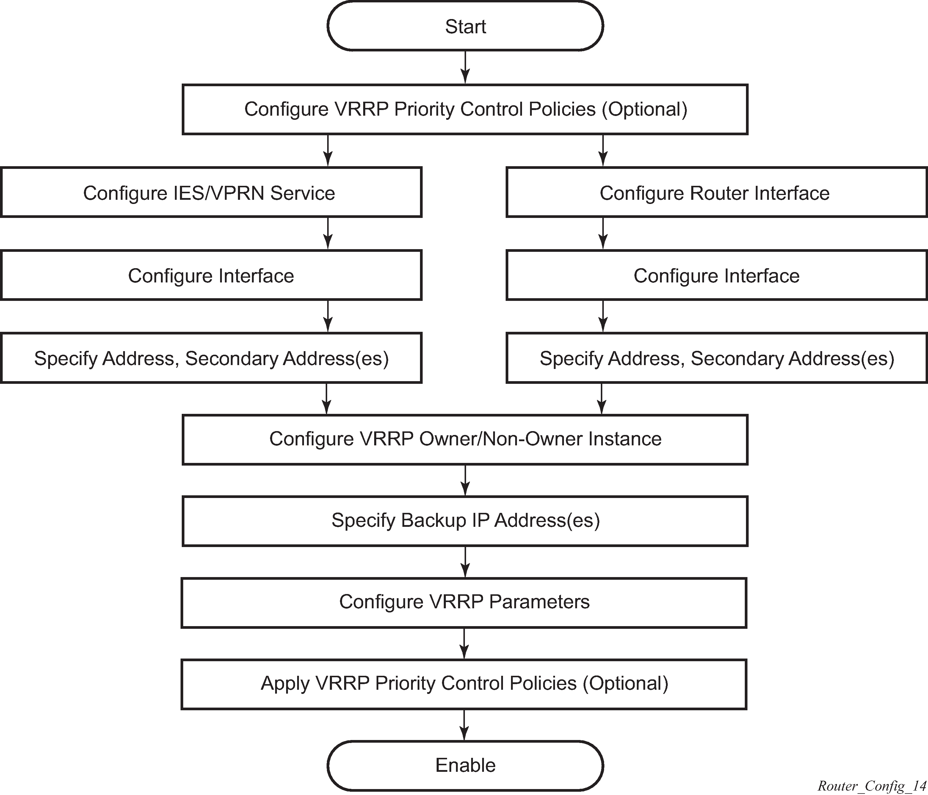
VRRP configuration process overview
VRRP configuration and implementation flow shows the process to configure and implement VRRP command options.
Configuration notes
This section describes VRRP configuration restrictions.
General
Creating and applying VRRP policies are optional.
Backup command:
The backup IP addresses must be on the same subnet. The backup addresses explicitly define which IP addresses are in the VRRP advertisement message IP address list.
In the owner mode, the backup IP address must be identical to one of the interface’s IP addresses. The backup address explicitly defines which IP addresses are in the VRRP advertisement message IP address list.
For IPv6, one of the backup addresses configured must be the link-local address of the owner VRRP instance.
Configuring VRRP with CLI
This section provides information to configure VRRP using the command line interface.
VRRP configuration overview
Configuring VRRP policies and configuring VRRP instances on interfaces and router interfaces is optional. The basic owner and non-owner VRRP configurations on an IES or router interface must specify the backup command option.
VRRP helps eliminate the single point of failure in a routed environment by using a virtual router IP address shared between two or more routers connecting the common domain. VRRP provides dynamic failover of the forwarding responsibility if the master becomes unavailable.
The VRRP implementation allows one master per IP subnet. All other VRRP instances in the same domain must be in backup mode.
Preconfiguration requirements
Configuring VRRP policies:
VRRP policies must be configured before they can be applied to an interface or IES/VPRN VRRP instance. VRRP policies are configured in the configure vrrp context.
Configuring VRRP on an IES or VPRN service interface:
The service customer account must be created before configuring an IES or VPRN VRRP instance.
The interface address must be specified in the both the owner and non-owner IES, VPRN, or router interface instances.
Basic VRRP configurations
Configure VRRP command options in the following contexts.
VRRP policy
Configuring and applying VRRP policies are optional. There are no default VRRP policies. Each policy must be explicitly defined. A VRRP configuration must include the following:
-
policy ID
-
at least one of the following priority events:
-
port down
-
LAG port down
-
host unreachable
-
route unknown
-
VRRP policy configuration for the 7450 ESS (MD-CLI)
*[ex:/configure vrrp policy 100]
A:admin@node-2# info
    delta-in-use-limit 50
    priority-event {
        host-unreachable "10.10.24.4" {
            drop-count 25
        }
        lag-port-down "lag-1" {
            number-down 3 {
                priority {
                    priority-level 50
                    event-type explicit
                }
            }
        }
        port-down 4/1/2 {
            hold-set 43200
            priority {
                priority-level 100
                event-type delta
            }
        }
        port-down 4/1/3 {
            priority {
                priority-level 200
                event-type explicit
            }
        }
        route-unknown 10.10.0.0/32 {
            priority {
                priority-level 50
                event-type delta
                }
        }
    }
VRRP policy configuration for the 7450 ESS (classic CLI)
A:node-2>config>vrrp>policy# info
----------------------------------------------
            delta-in-use-limit 50
            priority-event
                port-down 4/1/2
                    hold-set 43200
                    priority 100 delta
                exit
                port-down 4/1/3
                    priority 200 explicit
                exit
                lag-port-down 1
                    number-down 3
                        priority 50 explicit
                    exit
                exit
                host-unreachable 10.10.24.4
                    drop-count 25
                exit
                route-unknown 10.10.0.0/32
                    priority 50 delta
                    exit
            exit
----------------------------------------------
VRRP policy configuration for the 7750 SR and 7950 XRS (MD-CLI)
*[ex:/configure vrrp policy 100]
A:admin@node-2# info
    delta-in-use-limit 50
    priority-event {
        host-unreachable "10.10.24.4" {
            drop-count 25
        }
        port-down 4/1/2 {
            hold-set 43200
            priority {
                priority-level 100
                event-type delta
            }
        }
        port-down 4/1/3 {
            priority {
                priority-level 200
                event-type explicit
            }
        }
        route-unknown 10.10.0.0/32 {
            protocol [bgp]
            priority {
                priority-level 50
                event-type delta
            }
        }
    }
VRRP policy configuration for the 7750 SR and 7950 XRS (classic CLI)
A:node-2>config>vrrp>policy# info
----------------------------------------------
            delta-in-use-limit 50
            priority-event
                port-down 4/1/2
                    hold-set 43200
                    priority 100 delta
                exit
                port-down 4/1/3
                    priority 200 explicit
                exit
                lag-port-down 1
                    number-down 3
                        priority 50 explicit
                    exit
                exit
                host-unreachable 10.10.24.4
                    drop-count 25
                exit
                route-unknown 10.10.0.0/32
                    priority 50 delta
                    protocol bgp
                exit
            exit
----------------------------------------------
VRRP IES service configuration
VRRP is configured within an IES service with two contexts: owner or non-owner. The status is specified when the VRRP configuration is created. When configured as owner, the virtual router instance owns the backup IP addresses. All other virtual router instances participating in this message domain must have the same VRID configured and cannot be configured as owner.
For IPv4, up to four virtual router IDs can be configured on an IES service interface. Each virtual router instance can manage up to 16 backup IP addresses. For IPv6, only one virtual router instance can be configured on an IES service interface.
VRRP is configured within an IES service must include the following:
VRID
backup IP addresses
The following example shows an IES service owner and non-owner VRRP configuration.
MD-CLI
*[ex:/configure service ies "1"]
A:ex@node-2# info
    customer "1"
    interface "testing" {
        sap 1/1/55:0 {
        }
        ipv4 {
            primary {
                address 10.10.10.16
                prefix-length 24
            }
            vrrp 12 {
                authentication-key "testabc" hash2
                backup [10.10.10.15]
                policy 1
            }
        }
    }
    interface "tuesday" {
        sap 7/1/1.2.2 {
        }
        ipv4 {
            primary {
                    address 10.10.36.2
                    prefix-length 24
                }
                vrrp 19 {
                    authentication-key "testabc" hash2
                    backup [10.10.36.2]
                    owner true
                }
            }
        }
    }
classic CLI
A:node-2>config>service# info
----------------------------------------------
...
        ies 1 name "1" customer 1 create
            interface "tuesday" create
                address 10.10.36.2/24
                sap 7/1/1.2.2 create
                vrrp 19 owner
                    backup 10.10.36.2
                    authentication-key "testabc"
                exit
            exit
            interface "testing" create
                address 10.10.10.16/24
                sap 1/1/55:0 create
                vrrp 12
                    backup 10.10.10.15
                    policy 1
                    authentication-key "testabc"
                exit
            exit
            no shutdown
----------------------------------------------
Configure VRRP for IPv6
The following example shows a VRRP for IPV6 configuration and applies to the 7750 SR and 7950 XRS. The interface must be configured first.
MD-CLI
*[ex:/configure router "Base" ipv6 router-advertisement]
A:admin@node-2# info
    interface "Application-interface-101" {
        use-virtual-mac true
    }

*[ex:/configure service ies "100"]
A:admin@node-2# info
    description "Application VLAN 921"
    customer "1"
    interface "Application-interface-101" {
        sap ccag-1.a:921 {
            description "cross connect to VPLS 921"
        }
        ipv4 {
            primary {
                address 10.152.2.220
                prefix-length 28
            }
            vrrp 217 {
                backup [10.152.2.222]
                priority 254
                ping-reply true
            }
        }
        ipv6 {
            link-local-address {
                address fe80::d68f:1:221:fffd
                duplicate-address-detection false
            }
            address 2001:db8:d68f:1:221::fffd {
                prefix-length 64
            }
            vrrp 219 {
                backup [fe80::d68f:1:221:ffff]
                priority 254
                ping-reply true
            }
        }
    }
classic CLI
*A:node-2>config>router>router-advert# info
----------------------------------------------
            interface "Application-interface-101"
                use-virtual-mac
                no shutdown
            exit
...
----------------------------------------------

*A:node-2>config>service>ies# info
----------------------------------------------
            description "Application VLAN 921"
            interface "Application-interface-101" create
                address 10.152.2.220/28
                vrrp 217
                    backup 10.152.2.222
                    priority 254
                    ping-reply
                exit
                ipv6
                    address 2001:db8:D68F:1:221::FFFD/64
                    link-local-address fe80::d68f:1:221:fffd dad-disable
                    vrrp 219
                        backup fe80::d68f:1:221:ffff
                        priority 254
                        ping-reply
                    exit
                exit
                sap ccag-1.a:921 create
                    description "cross connect to VPLS 921"
                exit
            exit
            no shutdown
----------------------------------------------
VRRP router interface command options
VRRP command options are configured on a router interface with two contexts: owner or non-owner. The status is specified when the VRRP configuration is created. When configured as owner, the virtual router instance owns the backed up IP addresses. All other virtual router instances participating in this message domain must have the same VRID configured and cannot be configured as owner.
For IPv4, up to four virtual router IDs can be configured on a router interface. Each virtual router instance can manage up to 16 backup IP addresses. For IPv6, only one virtual router instance can be configured on a router interface.
VRRP command options configured on a router interface must include the following:
-
VRID
-
backup IP addresses
The following example shows a router interface owner and non-owner VRRP configuration.
MD-CLI
*[ex:/configure router "Base"]
A:admin@node-2#
...
    interface "system" {
    ipv4 {
            primary {
                address 10.10.0.4 {
                prefix-length 32
            }
        }
    }
    interface "test1" {
        ipv4 {
            primary {
                address 10.10.14.1
                prefix-length 24
            }
            secondary 10.10.16.1 {
                prefix-length 24
            }
            secondary 10.10.17.1 {
                prefix-length 24
            }
            secondary 10.10.18.1 {
                prefix-length 24
            }
        }
    }
    interface "test2" {
        ipv4 {
            primary {
                address 10.10.10.23
                prefix-length 24
            }
            vrrp 1 {
                authentication-key "testabc" hash2
                backup [10.10.10.23]
                owner true
            }
        }
    }
classic CLI
A:node-2>config>router# info
#------------------------------------------
echo "IP Configuration "
#------------------------------------------
        interface "system"
            address 10.10.0.4/32
        exit
        interface "test1"
            address 10.10.14.1/24
            secondary 10.10.16.1/24
            secondary 10.10.17.1/24
            secondary 10.10.18.1/24
        exit
        interface "test2"
            address 10.10.10.23/24
            vrrp 1 owner
                backup 10.10.10.23
                authentication-key "testabc"
            exit
        exit
#------------------------------------------
Common configuration tasks
This section provides a brief overview of the tasks that must be performed to configure VRRP and provides the CLI commands.
VRRP command options are defined under a service interface or a router interface context. An IP address must be assigned to each IP interface. Only one IP address can be associated with an IP interface but several secondary IP addresses also be associated.
Owner and non-owner configurations must include the following command options:
All participating routers in a VRRP instance must be configured with the same VRID.
All participating non-owner routers can specify up to 16 backup IP addresses (IP addresses that the master is representing). The owner configuration must include at least one backup IP address.
For IPv6, all participating routers must be configured with the same link-local backup address (the one configured for the owner instance).
Other owner and non-owner configurations include the following optional commands:
authentication-key
MAC
message-interval
In addition to the common command options, the following non-owner commands can be configured:
master-int-inherit
ntp-reply
priority
policy
ping-reply
preempt
telnet-reply
ssh-reply (IPv4 only)
[no] shutdown
Creating interface command options
If multiple subnets are configured on an Ethernet interface, VRRP can be configured on each subnet.
The following example shows an IP interface configuration.
MD-CLI
*[ex:/configure router "Base"]
A:admin@node-2# info
    router-id 10.10.0.1
    interface "system" {
    ipv4 {
            primary {
                address 10.10.0.1 {
                prefix-length 32
            }
        }
    }
    interface "testA" {
        ipv4 {
            primary {
                address 10.123.123.123
                prefix-length 24
            }
        }
    }
     interface "testB" {
        ipv4 {
            primary {
                address 10.10.14.1
                prefix-length 24
            }
            secondary 10.10.16.1 {
                prefix-length 24
            }
            secondary 10.10.17.1 {
                prefix-length 24
            }
            secondary 10.10.18.1 {
                prefix-length 24
            }
        }
    }
classic CLI
A:node-2>config>router# info
#------------------------------------------
echo "IP Configuration "
#------------------------------------------
        interface "system"
            address 10.10.0.1/32
        exit
        interface "testA"
            address 10.123.123.123/24
        exit
        interface "testB"
            address 10.10.14.1/24
            secondary 10.10.16.1/24
            secondary 10.10.17.1/24
            secondary 10.10.18.1/24
        exit
        router-id 10.10.0.1
#------------------------------------------
Configuring VRRP policy components
The following example shows VRRP policy component configurations.
MD-CLI
*[ex:/configure vrrp policy 1]
A:admin@node-2# info
    delta-in-use-limit 50
    priority-event {
        port-down 1/1/2 {
            hold-set 43200
            priority {
                priority-level 100
                event-type delta
            }
        }
        route-unknown 0.0.0.0/0 {
            protocol [isis]
        }
    }
classic CLI
A:node-2>config>vrrp# info
----------------------------------------------
        policy 1
            delta-in-use-limit 50
            priority-event
                port-down 1/1/2
                    hold-set 43200
                    priority 100 delta
                exit
                route-unknown 0.0.0.0/0
                    protocol isis
                exit
            exit
        exit
----------------------------------------------
Configuring service VRRP
VRRP command options can be configured on an interface in a service to provide virtual default router support, which allows traffic to be routed without relying on a single router in case of failure. VRRP can be configured in the following two ways.
Non-owner VRRP
The following example shows a basic non-owner VRRP configuration.
MD-CLI
*[ex:/configure service ies "100"]
A:admin@node-2# info
    interface "testing" {
        sap 1/1/55:0 {
         ipv4 {
            primary {
                address 10.10.10.16
                prefix-length 24
            }
        ipv4 {
            vrrp 12 {
                authentication-key "testabc"
                backup [10.10.10.15]
                policy 1
            }
        }
    }
classic CLI
A:node-2>config>service>ies# info
----------------------------------------------
            interface "testing" create
                address 10.10.10.16/24
                sap 1/1/55:0 create
                vrrp 12
                    backup 10.10.10.15
                    policy 1
                    authentication-key "testabc"
                exit
            exit
----------------------------------------------
Owner service VRRP
The following example shows an owner service VRRP configuration.
MD-CLI
*[ex:/configure router "Base" interface "test2"]
A:admin@node-2# info
    ipv4 {
        primary {
            address 10.10.10.23
            prefix-length 24
        }
        vrrp 1 {
            authentication-key "testabc"
            backup [10.10.10.23]
        }
    }
classic CLI
A:node-2>config>router# info
#------------------------------------------
echo "IP Configuration "
#------------------------------------------
...
        interface "test2"
            address 10.10.10.23/24
            vrrp 1 owner
                backup 10.10.10.23
                authentication-key "testabc"
            exit
        exit
#------------------------------------------
Configuring router interface VRRP command options
VRRP command options can be configured on an interface in an interface to provide virtual default router support, which allows traffic to be routed without relying on a single router in case of failure. VRRP can be configured in following two ways.
Router interface VRRP non-owner
The following example shows a router interface VRRP non-owner configuration.
MD-CLI
*[ex:/configure router "Base"]
A:admin@node-2# info
        interface "if-test" {
            ipv4 {
                primary {
                    address 10.20.30.40
                    prefix-length 24
                }
                secondary 10.10.50.1 {
                    prefix-length 24
                }
                secondary 10.10.60.1 {
                    prefix-length 24
                }
                secondary 10.10.70.1 {
                    prefix-length 24
                }
                vrrp 1 {
                    authentication-key "testabc" hash2
                    backup [10.10.50.2 10.10.60.2 10.10.70.2 10.20.30.41]
                    ping-reply true
                    telnet-reply true
                }
            }
classic CLI
A:node-2>config>router# info
#------------------------------------------
     interface "if-test"
            address 10.20.30.40/24
            secondary 10.10.50.1/24
            secondary 10.10.60.1/24
            secondary 10.10.70.1/24
            vrrp 1
                backup 10.10.50.2
                backup 10.10.60.2
                backup 10.10.70.2
                backup 10.20.30.41
                ping-reply
                telnet-reply
                authentication-key "testabc" hash2
            exit
        exit
#-----------------------------------------
Router interface VRRP owner
The following example shows a router interface VRRP owner configuration.
MD-CLI
*[ex:/configure router "Base"]
A:admin@node-2#
    }
    interface "vrrpowner" {
        ipv4 {
            primary {
                address 10.10.10.23
                prefix-length 24
            }
            vrrp 1 {
                authentication-key "testabc" hash2
                backup [10.10.10.23]
                owner true
            }
        }
    }
classic CLI
A:node-2>config>router# info
#------------------------------------------
     interface "vrrpowner"
            address 10.10.10.23/24
            vrrp 1 owner
                backup 10.10.10.23
                authentication-key "testabc" hash2
            exit
            no shutdown
        exit
#-----------------------------------------
VRRP configuration management tasks
This section describes VRRP configuration management tasks.
Modifying a VRRP policy
show vrrp policyThe following example shows the modified VRRP policy configuration.
MD-CLI
*[ex:/configure vrrp policy 100]
A:admin@node-2# info
    delta-in-use-limit 50
    priority-event {
        host-unreachable "10.10.24.4" {
            drop-count 25
        }
        port-down 1/1/2 {
            hold-set 43200
        }
        port-down 1/1/3 {
            priority {
                priority-level 200
                event-type explicit
            }
        }
    }
classic CLI
A:node-2>config>vrrp>policy# info
----------------------------------------------
            delta-in-use-limit 50
            priority-event
                port-down 1/1/2
                    hold-set 43200
                    priority 100 delta
                exit
                port-down 1/1/3
                    priority 200 explicit
                exit
                host-unreachable 10.10.24.4
                    drop-count 25
                exit
            exit
----------------------------------------------
Deleting a VRRP policy
VRRP policies are only applied to non-owner VRRP instances. A VRRP policy cannot be deleted if it is applied to an interface or to an IES service. Each instance in which the policy is applied must be deleted.
Use the following command to show where VRRP policies are applies to an entity.
show vrrp policyThe following example shows where VRRP policies are applied to an entity.
MD-CLI
===============================================================================
VRRP Policies
===============================================================================
Policy    Current             Current      Current      Delta Applied Svc
Id        Priority & Effect   Explicit     Delta Sum    Limit         Context
-------------------------------------------------------------------------------
1         200 Explicit        200          100          50          Yes
15        254                 None         None         1           No
32        100                 None         None         1           No
===============================================================================
classic CLI
===============================================================================
VRRP Policies
===============================================================================
Policy    Current             Current      Current      Delta       Applied
Id        Priority & Effect   Explicit     Delta Sum    Limit
-------------------------------------------------------------------------------
1         200 Explicit        200          100          50          Yes
15        254                 None         None         1           No
32        100                 None         None         1           No
===============================================================================
The following example shows the deletion of a VRRP policy.
MD-CLI
*[ex:/configure vrrp]
A:admin@node-2# delete policy 1

*[ex:/configure vrrp]
A:admin@node-2# commit
classic CLI
*A:node-2>config>vrrp# no policy 1
Modifying service and interface VRRP command options
Modifying non-owner command options
After a VRRP instance is created as non-owner, it cannot be modified to the owner state. The VRID must be deleted, then recreated with the owner keyword, to invoke IP address ownership.
Modifying owner command options
After a VRRP instance is created as owner, it cannot be modified to the non-owner state. The VRID must be deleted, then recreated without the owner keyword, to remove IP address ownership.
Entering the owner command option is optional when entering the VRID for modification purposes.
Deleting VRRP from an interface or service
The VRID does not need to be shutdown to remove the virtual router instance from an interface or service. Use the following command to remove the virtual router instance:
-
MD-CLI
configure service ies interface ipv4 delete vrrp -
classic CLI
configure service ies interface vrrp shutdown
configure service ies interface no vrrp