IS-IS
Configuring IS-IS
Intermediate-system-to-intermediate-system (IS-IS) is a link-state interior gateway protocol (IGP) which uses the Shortest Path First (SPF) algorithm to determine routes. Routing decisions are made using the link-state information. IS-IS evaluates topology changes and, if necessary, performs SPF recalculations.
Entities within IS-IS include networks, intermediate systems, and end systems. In IS-IS, a network is an autonomous system (AS), or routing domain, with end systems and intermediate systems. A router is an intermediate system. End systems are network devices which send and receive protocol data units (PDUs), the OSI term for packets. Intermediate systems send, receive, and forward PDUs.
End system and intermediate system protocols allow routers and nodes to identify each other. IS-IS sends out link-state updates periodically throughout the network, so each router can maintain current network topology information.
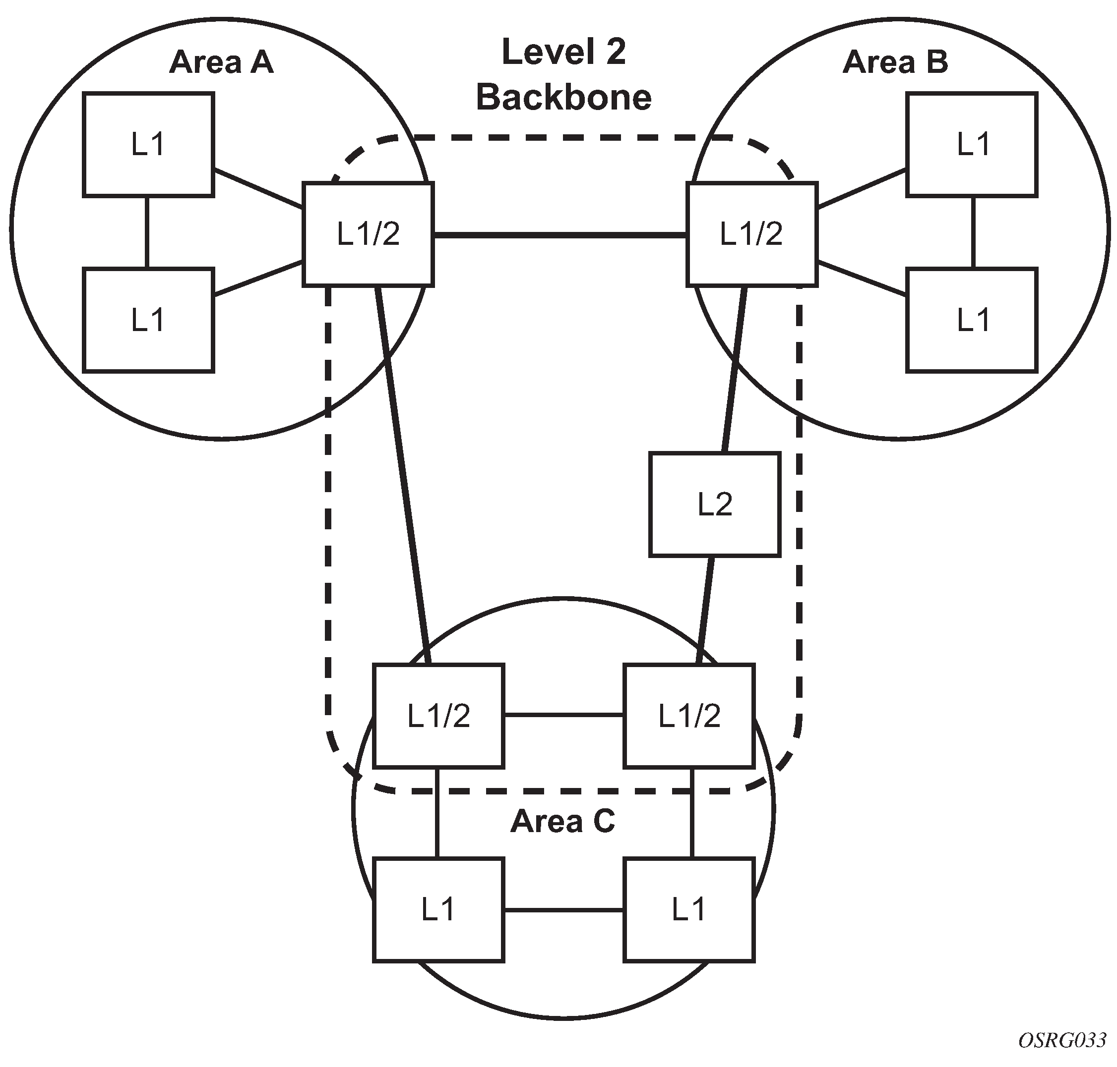
IS-IS supports large ASs by using a two-level hierarchy. A large AS can be administratively divided into smaller, more manageable areas. A system logically belongs to one area. Level 1 routing is performed within an area. Level 2 routing is performed between areas. The routers can be configured as level 1, level 2, or both level 1/2.
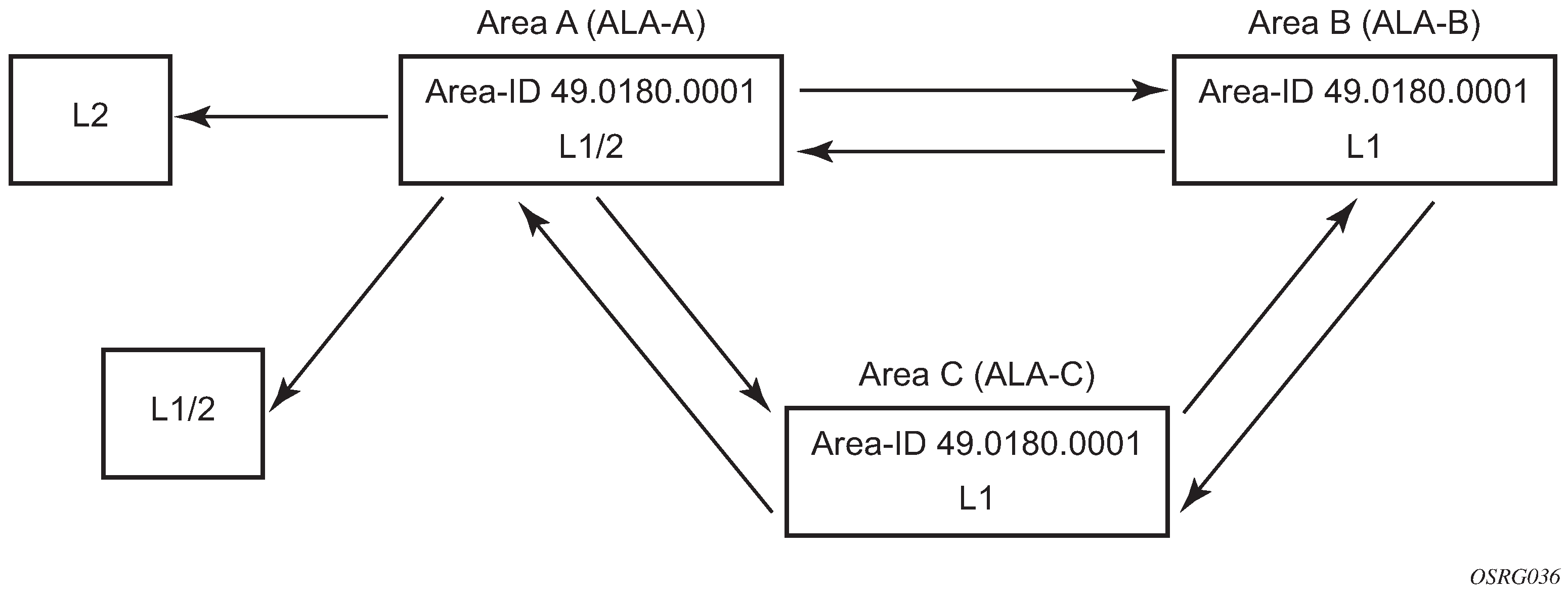
IS-IS routing domain displays an example of an IS-IS routing domain.
Routing
OSI IS-IS routing uses two-level hierarchical routing. A routing domain can be partitioned into areas. Level 1 routers know the topology in their area, including all routers and end systems in their area but do not know the identity of routers or destinations outside of their area. Level 1 routers forward traffic with destinations outside of their area to a level 2 router in their area.
Level 2 routers know the level 2 topology, and know which addresses are reachable by each level 2 router. Level 2 routers do not need to know the topology within any level 1 area, except to the extent that a level 2 router can also be a level 1 router within a single area. By default, only level 2 routers can exchange PDUs or routing information directly with external routers located outside the routing domain.
The two types of routers in IS-IS are described below.
Level 1 intermediate systems
Routing is performed based on the area ID portion of the ISO address called the Network Entity Title (NET). Level 1 systems route within an area. They recognize, based on the destination address, whether the destination is within the area. If so, they route toward the destination. If not, they route to the nearest level 2 router.
Level 2 intermediate systems
Routing is performed based on the area address. They route toward other areas, regardless of other area’s internal structure. A level 2 intermediate system can also be configured as a level 1 intermediate system in the same area.
The level 1 router’s area address portion is manually configured (see ISO network addressing). A level 1 router does not become a neighbor with a node that does not have a common area address. However, if a level 1 router has area addresses A, B, and C, and a neighbor has area addresses B and D, then the level 1 router accepts the other node as a neighbor, as address B is common to both routers. Level 2 adjacencies are formed with other level 2 nodes whose area addresses do not overlap. If the area addresses do not overlap, the link is considered by both routers to be level 2 only and only level 2 LSPDUs flow on the link.
Within an area, level 1 routers exchange LSPs which identify the IP addresses reachable by each router. Specifically, zero or more IP address, subnet mask, and metric combinations can be included in each LSP. Each level 1 router is manually configured with the IP address, subnet mask, and metric combinations, which are reachable on each interface. A level 1 router routes as follows:
if a specified destination address matches an IP address, subnet mask, or metric reachable within the area; the PDU is routed via level 1 routing
if a specified destination address does not match any IP address, subnet mask, or metric combinations listed as reachable within the area; the PDU is routed toward the nearest level 2 router
Level 2 routers include in their LSPs, a complete list of IP address, subnet mask, and metrics specifying all the IP addresses which reachable in their area. This information can be obtained from a combination of the level 1 LSPs (by level 1 routers in the same area). Level 2 routers can also report external reachability information, corresponding to addresses reachable by routers in other routing domains or autonomous systems.
IS-IS frequently used terms
Area
An area is a routing sub-domain which maintains detailed routing information about its own internal composition, and also maintains routing information which allows it to reach other routing sub-domains. Areas correspond to the level 1 sub-domain.
End system
End systems send NPDUs to other systems and receive NPDUs from other systems, but do not relay NPDUs. This International Standard does not specify any additional end system functions beyond those supplied by ISO 8473 and ISO 9542.
Neighbor
A neighbor is an adjacent system reachable by traversing a single sub-network by a PDU.
Adjacency
An adjacency is a portion of the local routing information which pertains to the reachability of a single neighboring end or intermediate system over a single circuit. Adjacencies are used as input to the decision process to form paths through the routing domain. A separate adjacency is created for each neighbor on a circuit and for each level of routing (level 1 and level 2) on a broadcast circuit.
Circuit
The subset of the local routing information base pertinent to a single local Subnetwork Point of Attachments (SNPAs).
Link
The communication path between two neighbors. A link is up when communication is possible between the two SNPAs.
Designated IS
The intermediate system on a LAN which is designated to perform additional duties. In particular, the designated IS generates link-state PDUs on behalf of the LAN, treating the LAN as a pseudonode.
Pseudonode
Where a broadcast sub-network has n connected intermediate systems, the broadcast sub-network itself is considered to be a pseudonode. The pseudonode has links to each of the n intermediate systems and each of the ISs has a single link to the pseudonode (instead of n-1 links to each of the other intermediate systems). Link-state PDUs are generated on behalf of the pseudonode by the designated IS.
Broadcast sub-network
A multi-access subnetwork that supports the capability of addressing a group of attached systems with a single PDU.
General topology sub-network
A topology that is modeled as a set of point-to-point links, each of which connects two systems. There are several generic types of general topology subnetworks, multipoint links, permanent point-to-point links, dynamic and static point-to-point links.
Routing sub-domain
A routing sub-domain consists of a set of intermediate systems and end systems located within the same routing domain.
Level 2 sub-domain
Level 2 sub-domain is the set of all level 2 intermediate systems in a routing domain.
ISO network addressing
IS-IS uses ISO network addresses. Each address identifies a point of connection to the network, such as a router interface, and is called a Network Service Access Point (NSAP).
An end system can have multiple NSAP addresses, in which case the addresses differ only by the last byte (called the n selector). Each NSAP represents a service that is available at that node. In addition to having multiple services, a single node can belong to multiple areas.
Each network entity has a special network address called a Network Entity Title (NET). Structurally, a NET is identical to an NSAP address but has an n-selector of 00. Most end systems have one NET. Intermediate systems can have up to three area IDs (area addresses).
NSAP addresses are divided into three parts. Only the area ID portion is configurable.
Area ID
A variable length field between 1 and 13 bytes long. This includes the Authority and Format Identifier (AFI) as the most significant byte and the area ID.
System ID
A six-byte system identification. This value is not configurable. The system ID is derived from the system or router ID.
Selector ID
A one-byte selector identification that must contain zeros when configuring a NET. This value is not configurable. The selector ID is always 00.
Of the total 20 bytes comprising the NET, only the first 13 bytes, the area ID portion, can be manually configured. As few as one byte can be entered or, at most, 13 bytes. If less than 13 bytes are entered, the rest is padded with zeros.
Routers with common area addresses form level 1 adjacencies. Routers with no common NET addresses form level 2 adjacencies, if they are capable (Using area addresses to form adjacencies).
IS-IS PDU configuration
The following PDUs are used by IS-IS to exchange protocol information:
IS-IS hello PDU
Routers with IS-IS enabled send hello PDUs to IS-IS-enabled interfaces to discover neighbors and establish adjacencies.
Link-state PDUs
Contain information about the state of adjacencies to neighboring IS-IS systems. LSPs are flooded periodically throughout an area.
Complete sequence number PDUs
In order for all routers to maintain the same information, CSNPs inform other routers that some LSPs can be outdated or missing from their database. CSNPs contain a complete list of all LSPs in the current IS-IS database.
Partial sequence number PDUs (PSNPs)
PSNPs are used to request missing LSPs and acknowledge that an LSP was received.
IS-IS operations
-
Hello PDUs are sent to the IS-IS-enabled interfaces to discover neighbors and establish adjacencies.
-
IS-IS neighbor relationships are formed if the hello PDUs contain information that meets the criteria for forming an adjacency.
-
The routers can build a link-state PDU based upon their local interfaces that are configured for IS-IS and prefixes learned from other adjacent routers.
-
The routers flood LSPs to the adjacent neighbors except the neighbor from which they received the same LSP. The link-state database is constructed from these LSPs.
-
A Shortest Path Tree (SPT) is calculated by each IS, and from this SPT the routing table is built.
IS-IS route summarization
IS-IS route summarization allows users to create aggregate IPv4 or IPv6 addresses that include multiple groups of IPv4 or IPv6 addresses for a specific IS-IS level. IPv4 and IPv6 routes redistributed from other routing protocols also can be summarized. This is similar to OSPF configuration using the area-range command. IS-IS IPv4 and IPv6 route summarization helps to reduce the size of the LSDB and the IPv4 or IPv6 routing table, and reduces the chance of route flapping.
IS-IS route summarization supports:
level 1, level 1-2, and level 2
route summarization for the IPv4 or IPv6 routes redistributed from other protocols
the smallest metric used to advertise summary addresses of all the more specific IPv4 or IPv6 routes
IS-IS IPv6 route summarization algorithm and SRv6 locator awareness
Partial SPF calculation
IS-IS supports partial SPF calculation, also referred to as partial route calculation. When an event does not change the topology of the network, IS-IS is not perform full SPF but instead performs an IP reach calculation for the impacted routes. Partial SPF is performed at the receipt of IS-IS LSPs with changes to IP reach TLVs and in general, for any IS-IS LSP TLV and sub-TLV change that does not impact the network topology.
IS-IS multi-topology support
Multi-Topology IS-IS (MT-ISIS) support within SR OS allows for the creation of different topologies within IS-IS that contribute routes to specific route tables for IPv4 unicast, IPv6 unicast, IPv4 multicast, and IPv6 multicast. This capability allows for non-congruent topologies between these different routing tables. As a result, networks are able to control which links or nodes are to be used for forwarding different types of traffic.
For example, MT-ISIS could allow all links to carry IPv4 traffic, while only a subset of links can also carry IPv6 traffic.
SR OS supports the following multi-topologies:
IPv4 Unicast – MT-ID 0
IPv6 Unicast – MT-ID 2
IPv4 Multicast – MT-ID 3
IPv6 Multicast – MT-ID 4
Native IPv6 support
IS-IS IPv6 TLVs for IPV6 routing is supported in SR OS. This support is considered native IPv6 routing within IS-IS. However, it has limitations in that IPv4 and IPv6 topologies must be congruent, otherwise traffic may be blackholed. Service providers should ensure that the IPv4 topology and IPv6 topologies are the same if native IPv6 routing is used within IS-IS.
IS-IS administrative tags
IS-IS administrative tags enable a network administrator to configure route tags to tag IS-IS route prefixes. These tags can subsequently be used to control IS-IS route redistribution or route leaking.
IS-IS route tagging can be applied to IP addresses of an interface and to administrative policies with a route map. A network administrator can tag a summary route and then use a route policy to match the tag with one or more attributes for the route.
Using these administrative policies, the operator can control how a router handles route exchanges with its IS-IS neighboring routers. Administrative policies are also used to govern the installation of routes in the routing table.
Route tags allow policies to do the following:
redistribute routes received from other protocols in the routing table to IS-IS
redistribute routes or SRv6 locators between levels in an IS-IS routing hierarchy
summarize routes redistributed into IS-IS or within IS-IS by creating aggregate (summary) addresses
Setting route tags
IS-IS route tags are configurable in the following ways:
for an IS-IS interface
on an IS-IS passive interface
for a route redistributed from another protocol to IS-IS
for a route redistributed from one IS-IS level to another IS-IS level
for an IS-IS default route
for an IS-IS summary address or SRv6 locator
Using route tags
Although an operator on this or on a neighboring IS-IS router has configured the setting of the IS-IS administrative tags, it does not have any effect unless policies are configured to instruct how to process the specified tag value.
Policies can process tags where IS-IS is either the origin, destination or both origin and destination protocol.
config>router>policy-options>policy-statement>entry>from
     config>router>policy-options>policy-statement>entry>action tag tag-value
     config>router>policy-options>policy-statement# default-action tag tag-value
Unnumbered interface support
IS-IS supports unnumbered point-to-point interface with both Ethernet and PPP encapsulations.
Unnumbered interfaces borrow the address from other interfaces such as system or loopback interfaces and uses it as the source IP address for packets originated from the interface. This feature supports both dynamic and static ARP for unnumbered interfaces to allow interworking with unnumbered interfaces that may not support dynamic ARP.
An unnumbered interface is an IPv4 capability only used in cases where IPv4 is active (IPv4-only and mixed IPv4/IPv6 environments). When configuring an unnumbered interface, the interface specified for the unnumbered interface (system or other) must have an IPv4 address. Also, the interface type for the unnumbered interface automatically is point-to-point. The unnumbered option can be used in IES and VPRN access interfaces, as well as in a network interface with MPLS support.
Multi-homed prefix LFA extensions in IS-IS
Feature configuration
Use the following command to configure the Multi-Homed Prefix (MHP) LFA feature for IP FRR for IS-IS routes, SR-ISIS tunnel, and SRv6-ISIS tunnel FRR:
- MD-CLI
configure router isis loopfree-alternate multi-homed-prefix preference - classic
CLI
configure router isis loopfree-alternates multi-homed-prefix preference
When applied to IP prefixes, IP FRR must also be enabled. Use the following command to allow the programming of the backup paths in the FIB:
- MD-CLI
configure routing-options ip-fast-reroute - classic
CLI
configure router ip-fast-reroute
This feature uses the multihomed prefix model described in RFC 8518 to compute a backup IP next hop via an alternate ABR or ASBR for external prefixes and to an alternate router owner for local anycast prefixes. Without this feature, the backup path is computed to the ASBR, ABR, or router owner, which is the best path for the prefix.
This feature further enhances the multihomed prefix backup path calculation beyond RFC 8518 with the addition of repair tunnels that make use of a PQ node or a P-Q set to reach the alternate exit ABR or ASBR of external prefixes or the alternate owner router of intra-area anycast prefixes.
The base LFA algorithm is applied to all intra-area and external prefixes of IP routes (IP FRR), of SR-ISIS node SID tunnels (SR-ISIS FRR), and to SRv6-ISIS remote locator tunnels (SRv6-ISIS FRR), as usual. Then the MHP LFA is applied to improve the protection coverage for external prefixes and anycast prefixes. For external /32 IPv4 prefixes and /128 IPv6 prefixes and for intra-area /32 IPv4 and /128 IPv6 prefixes with multiple owner routers (anycast prefixes), the base LFA backup path, if found, is preferred over the MHP LFA backup path in the default behavior with the preference command set to a value of none. The user can force the programming of the MHP LFA backup path by setting preference command value to all.
After the IP next-hop based MHP LFA is enabled, the extensions to MHP LFA to compute an SR-TE repair tunnel for an SR-ISIS or SRv6-ISIS tunnel are automatically enabled when the following CLI command is configured to enable Topology-Independent Loop-Free Alternate (TI-LFA) or Remote Loop-Free Alternate (RLFA). The computation reuses the SID list of the primary path or the TI-LFA or RLFA backup path of the alternate ABR, ASBR, or alternate owner router.
- MD-CLI
configure router isis loopfree-alternate remote-lfa configure router isis loopfree-alternate ti-lfa - classic
CLI
configure router isis loopfree-alternates remote-lfa
configure router isis loopfree-alternates ti-lfa
TI-LFA, base LFA, and RLFA (if enabled) are applied to the SR-ISIS node SID tunnels of all intra-area and external /32 IPv4 and /128 IPv6 prefixes as usual, and to all SRv6-ISIS locator tunnels of intra-area and external prefixes of any size.
For node SID SR-ISIS tunnels of external /32 IPv4 and /128 IPv6 prefixes or intra-area /32 IPv4 and /128 IPv6 anycast prefixes, the LFA, TI-LFA, or RLFA backup path is preferred over the MHP LFA backup path in the default behavior with the preference command set to a value of none. The user can force the programming of the MHP LFA backup by setting the preference command value to all. Finally, the same preference rule also applies to SRv6-ISIS remote locator tunnels of external prefixes and intra-area prefixes with multiple router owners.
The MHP LFA backup path protects SR-ISIS tunnels and SRv6-ISIS locator tunnels in both algorithm 0 and flexible-algorithm numbers. Therefore, it also extends the protection to any SR-TE LSP, SR-MPLS policy, or SRv6 policy that uses an SR-ISIS SID or an SRv6-ISIS SID of those same prefixes in its configured or computed SID list.
Feature applicability
The multi-homed-prefix command enables the feature, but its applicability depends on the LFA flavor enabled in the IS-IS instance. The following scenarios are possible:
- Scenario 1
- MD-CLI
The loopfree-alternate and multi-homed-prefix commands are enabled.
- classic CLI
The loopfree-alternates and multi-homed-prefix commands are enabled.
The IP next-hop based MHP LFA feature enhances base LFA only; it applies to IP FRR (when the ip-fast-reroute command is also enabled) and to SR-ISIS tunnels and SRv6-ISIS tunnels.
- MD-CLI
- Scenario 2
- MD-CLI
The loopfree-alternate remote-lfa and loopfree-alternate ti-lfa commands are enabled, or both commands and the multi-homed-prefix command is enabled.
- classic CLI
The loopfree-alternates remote-lfa and loopfree-alternates ti-lfa commands are enabled, or both commands and the multi-homed-prefix command is enabled.
The enabling of RLFA, TI-LFA, or both on top of the MHP LFA automatically enables the SR OS specific enhancements to RFC 8515 that compute a repair tunnel to the alternate exit ABR or ASBR of external prefixes or to the alternate owner router for intra-area anycast prefixes. This enhancement improves coverage because it computes a SR-TE or SRv6 backup repair tunnel to an alternate ASBR. This forces the packet to go to the alternate ASBR because the RFC 8518 MHP LFA may not find a loop-free path to this alternate ASBR.
- MD-CLI
RFC 8518 MHP LFA for IS-IS
The behavior of this feature is the same as in OSPF. See Multi-homed prefix LFA extensions in OSPF.
FIB prioritization
The RIB processing of specific routes can be prioritized through the use of the rib-priority command. This command allows specific routes to be prioritized through the protocol processing so that updates are propagated to the FIB as quickly as possible.
The rib-priority command is configured within the global IS-IS routing context, and the administrator has the option to either specify a prefix list or an IS-IS tag value. If a prefix list is specified, route prefixes matching any of the prefix list criteria is considered high priority. If instead an IS-IS tag value is specified, any IS-IS route with that tag value is considered high priority.
Routes designated as high priority are the first routes processed and passed to the FIB update process so that the forwarding engine can be updated. All known high priority routes should be processed before the IS-IS routing protocol moves on to other standard priority routes. This feature has the most impact when a large number of routes are learned through the IS-IS routing protocols.
IS-IS graceful restart helper
IS-IS supports the graceful restart helper function which provides an IS-IS neighbor a grace period during a control plane restart to minimize service disruption. When the control plane of a GR-capable router fails or restarts, the neighboring routers supporting the graceful restart helper mode (GR helpers) temporarily preserve IS-IS forwarding information. Traffic continues to be forwarded to the restarting router using the last known forwarding tables. If the control plane of the restarting router comes back up within the grace period, the restarting router resumes normal IS-IS operation. If the grace period expires, then the restarting router is presumed inactive and the IS-IS topology is recalculated to route traffic around the failure.
BFD interaction with graceful restart
If the SR OS router is providing a grace period to an adjacent neighbor and the BFD session associated with that neighbor fails, the behavior is determined by the C-bit values sent by each neighbor.
If both BFD end-points have set their C-bit value, then the graceful restart helper mode is canceled and any routes from that neighbor that are marked as stale are removed from the forwarding table.
If either of the BFD end-points has not set their C-bit value, then the graceful restart helper mode continues.
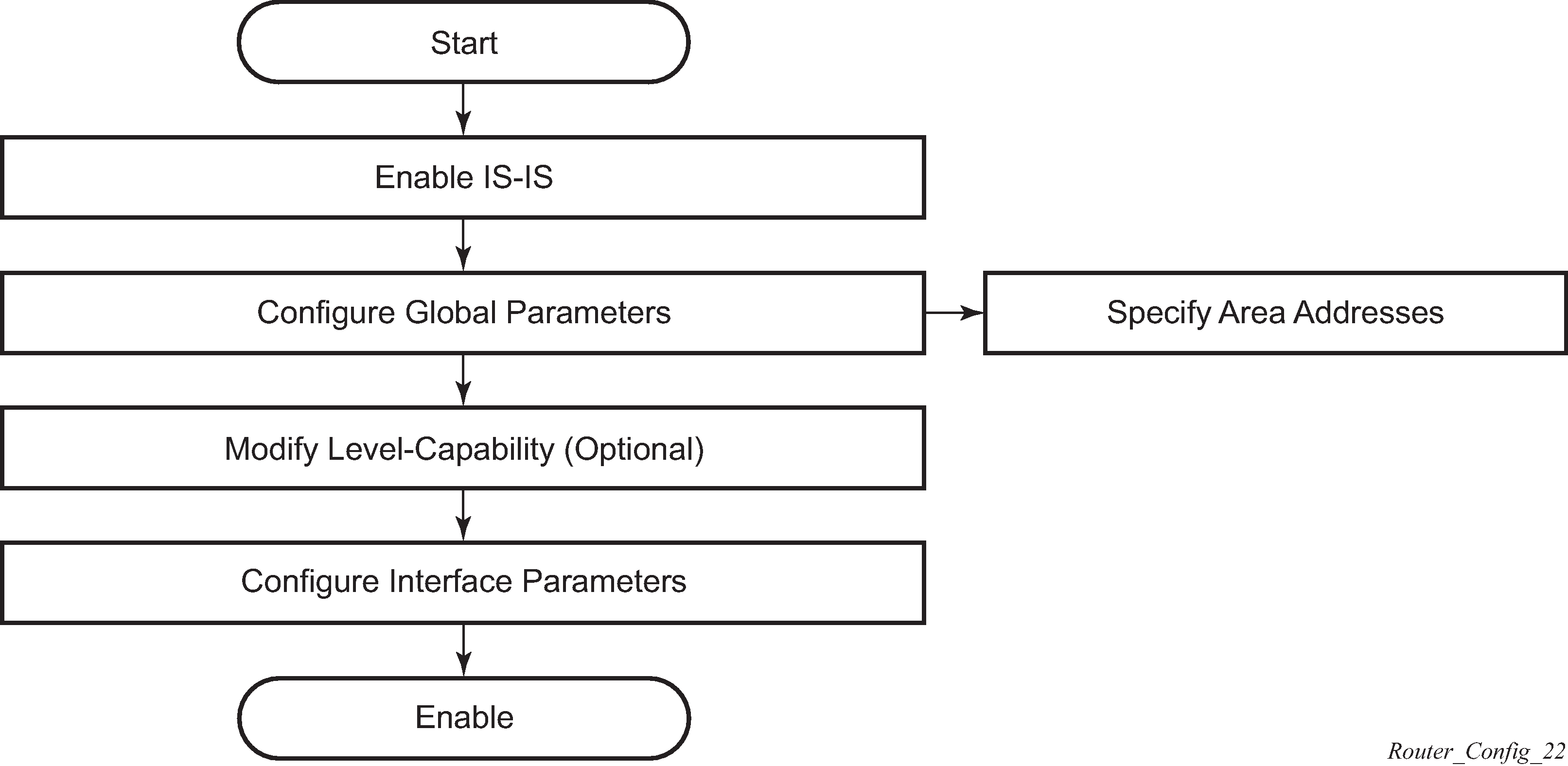
IS-IS configuration process overview
IS-IS configuration and implementation flow displays the process to provision basic IS-IS parameters.
Configuration notes
This section describes IS-IS configuration restrictions.
General
IS-IS must be enabled on each participating router.
There are no default network entity titles.
There are no default interfaces.
By default, the routers are assigned a level 1/level 2 level capability.
Configuring IS-IS with CLI
This section provides information to configure IS-IS using the command line interface.
IS-IS configuration overview
Router levels
The router’s level capability can be configured globally and on a per-interface basis. The interface-level parameters specify the interface’s routing level. The neighbor capability and parameters define the adjacencies that are established.
IS-IS is not enabled by default. When IS-IS is enabled, the global default level capability is level 1/2 which enables the router to operate as either a level 1 and/or a level 2 router with the associated databases. The router runs separate shortest path first (SPF) calculations for the level 1 area routing and for the level 2 multi-area routing to create the IS-IS routing table.
The level value can be modified on both or either of the global and interface levels to be only level 1-capable, only level 2-capable or level 1 and level 2-capable.
If the default value is not modified on any routers in the area, then the routers try to form both level 1 and level 2 adjacencies on all IS-IS interfaces. If the default values are modified to level 1 or level 2, then the number of adjacencies formed are limited to that level only.
Configuring area address attributes
The area-id command specifies the area address portion of the NET which is used to define the IS-IS area to which the router belongs. At least one area-id command should be configured on each router participating in IS-IS. A maximum of three area-id commands can be configured per router.
The area address identifies a point of connection to the network, such as a router interface, and is called a Network Service Access Point (NSAP). The routers in an area manage routing tables about destinations within the area. The Network Entity Title (NET) value is used to identify the IS-IS area to which the router belongs.
NSAP addresses are divided into three parts. Only the Area ID portion is configurable.
-
Set the area ID.
A variable length field between 1 and 13 bytes long. This includes the Authority and Format Identifier (AFI) as the most significant byte and the area ID.
-
Set the system ID.
A six-byte system identification. This value is not configurable. The system ID is derived from the system or router ID.
-
Set the selector ID.
A one-byte selector identification that must contain zeros when configuring a NET. This value is not configurable. The selector ID is always 00.
The following example displays ISO addresses in IS-IS address format:MAC address 00:a5:c7:6b:c4:9049.0011.00a5.c76b.c490.00 IP address: 218.112.14.5 49.0011.2181.1201.4005.00
Interface level capacity
The level capability value configured on the interface level is compared to the level capability value configured on the global level to determine the type of adjacencies that can be established. The default level capability for routers and interfaces is level 1/2.
Potential adjacency displays configuration combinations and the potential adjacencies that can be formed.
| Global level | Interface level | Potential adjacency |
|---|---|---|
L 1/2 |
L 1/2 |
Level 1 and/or Level 2 |
L 1/2 |
L 1 |
Level 1 only |
L 1/2 |
L 2 |
Level 2 only |
L 2 |
L 1/2 |
Level 2 only |
L 2 |
L 2 |
Level 2 only |
L 2 |
L 1 |
— |
L 1 |
L 1/2 |
Level 1 only |
L 1 |
L 2 |
— |
L 1 |
L 1 |
Level 1 only |
Route leaking
Nokia’s implementation of IS-IS route leaking is performed in compliance with RFC 2966, Domain-wide Prefix Distribution with Two-Level IS-IS. As previously stated, IS-IS is a routing domain (an autonomous system running IS-IS) which can be divided into level 1 areas with a level 2-connected subset (backbone) of the topology that interconnects all of the level 1 areas. Within each level 1 area, the routers exchange link state information. Level 2 routers also exchange level 2 link state information to compute routes between areas.
Routers in a level 1 area typically only exchange information within the level 1 area. For IP destinations not found in the prefixes in the level 1 database, the level 1 router forwards PDUs to the nearest router that is in both level 1/level 2 with the attached bit set in its level 1 link-state PDU.
There are many reasons to implement domain-wide prefix distribution. The goal of domain-wide prefix distribution is to increase the granularity of the routing information within the domain. The routing mechanisms specified in RFC 1195 are appropriate in many situations and account for excellent scalability properties. However, in specific circumstances, the amount of scalability can be adjusted which can distribute more specific information than described by RFC 1195.
Distributing more prefix information can improve the quality of the resulting routes. A well-known property of default routing is that loss of information can occur. This loss of information affects the computation of a route based upon less information which can result in sub-optimal routes.
Basic IS-IS configuration
For IS-IS to operate on the routers, IS-IS must be explicitly enabled, and at least one area address and interface must be configured. If IS-IS is enabled but no area address or interface is defined, the protocol is enabled but no routes are exchanged. When at least one area address and interface are configured, then adjacencies can be formed and routes exchanged.
-
Enable IS-IS (specifying the instance ID of multi-instance IS-IS is to be enabled).
-
Modify the level capability, if necessary, on the global level (default is level-1/2).
-
Define area addresses.
-
Configure IS-IS interfaces.
The following output displays IS-IS default values.
*A:Dut-D>config>router>isis# info detail
----------------------------------------------
           no system-id
           no router-id
           level-capability level-1/2
           no graceful-restart
           no auth-keychain
           no authentication-key
           no authentication-type
           authentication-check
           csnp-authentication
           no ignore-lsp-errors
           no ignore-narrow-metric
           lsp-lifetime 1200
           lsp-mtu-size 1492
           lsp-refresh-interval 600
           no export-limit
           no export
           no import
           hello-authentication
           psnp-authentication
           no traffic-engineering
           no reference-bandwidth
           no default-route-tag
           no disable-ldp-sync
           no advertise-passive-only
           no advertise-router-capability
           no hello-padding
           no ldp-over-rsvp
           no advertise-tunnel-link
           no ignore-attached-bit
           no suppress-attached-bit
           no iid-tlv-enable
           no poi-tlv-enable
           no prefix-limit
           no loopfree-alternates
           no rib-priority high
           ipv4-routing
           no ipv6-routing
           ipv4-multicast-routing native
           ipv6-multicast-routing native
           no multi-topology
           no unicast-import-disable both
           no multicast-import both
           no strict-adjacency-check
           igp-shortcut
               shutdown
               tunnel-next-hop
                   family ipv4
                       resolution disabled
                       resolution-filter
                           no rsvp
                           no sr-te
                   exit
                   family ipv6
                       resolution disabled
                       resolution-filter
                           no rsvp
                           no sr-te
                   exit
                   family srv4
                       resolution disabled
                       resolution-filter
                           no rsvp
                           no sr-te
                   exit
                   family srv6
                       resolution disabled
                       resolution-filter
                           no rsvp
                           no sr-te
                   exit
               exit
           exit
           timers
               lsp-wait 5000 lsp-initial-wait 10 lsp-second-wait 1000
               sfp-wait 10000 sfp-initial-wait 1000 sfp-second-wait 1000
           exit
           level 1
               advertise-router-capability
               no hello-padding
               no lsp-mtu-size
               no auth-keychain
               no authentication-key
               no authentication-type
               csnp-authentication
               external-preference 160
               hello-authentication
               no loopfree-alternate-exclude
               preference 15
               psnp-authentication
               no wide-metrics-only
               default-metric 10
              default-ipv4-multicast-metric 10
               default-ipv6-unicast-metric 10
               default-ipv6-multicast-metric 10
           exit
           level 2
               advertise-router-capability
               no hello-padding
               no lsp-mtu-size
               no auth-keychain
               no authentication-key
               no authentication-type
               csnp-authentication
               external-preference 165
              hello-authentication
               no loopfree-alternate-exclude
               preference 18
               psnp-authentication
               no wide-metrics-only
               default-metric 10
               default-ipv4-multicast-metric 10
               default-ipv6-unicast-metric 10
               default-ipv6-multicast-metric 10
           exit
           segment-routing
               shutdown
               adj-sid-hold 15
               no export-tunnel-table
               no prefix-sid-range
               no tunnel-table-pref
               no tunnel-mtu
               mapping-server
                   shutdown
               exit
           exit
           no shutdown
Common configuration tasks
To implement IS-IS in your network, you must enable IS-IS on each participating router.
To assign different level to the routers and organize your network into areas, modify the level capability defaults on end systems from level 1/2 to level 1. Routers communicating to other areas can retain the level 1/2 default.
-
Enable IS-IS.
-
Configure global IS-IS parameters (configure area addresses).
-
Configure IS-IS interface-specific parameters.
Configuring IS-IS components
Use the CLI syntax displayed in the following subsections to configure IS-IS components.
Enabling IS-IS
IS-IS must be enabled in order for the protocol to be active.
To configure IS-IS on a router, enter the following command.
CLI syntax
isisExample
config>router# isisIS-IS also supports the concept of multi-instance IS-IS which allows separate instances of the IS-IS protocol to run independently of the SR OS router.
Separate instances are created by adding a different instance ID as the optional parameter to the config>router>isis command.
Modifying router-level parameters
When IS-IS is enabled, the default level-capability is level 1/2. This means that the router operates with both level 1 and level 2 routing. To change the default value in order for the router to operate as a level 1 router or a level 2 router, you must explicitly modify the level value.
If the level is modified, the protocol shuts down and restarts. Doing this can affect adjacencies and routes.
The level-capability value can be configured on the global level and also on the interface level. The level-capability value determines which level values can be assigned on the router level or on an interface-basis.
In order for the router to operate as a level 1 only router or as a level 2 only router, you must explicitly specify the level-number value.
Select level-1 to route only within an area.
Select level-2 to route to destinations outside an area, toward other eligible level 2 routers.
To configure the router level, enter the following commands:
config>router# isis
  level-capability {level-1|level-2|level-1/2}
  level {1|2}
Example
config>router# isis
config>router>isis# level-capability 1/2
config>router>isis# level 2
The following example displays the configuration:
A:ALA-A>config>router>isis# info
#------------------------------------------
echo "ISIS"
#------------------------------------------

level-capability level-1/2
level 2

----------------------------------------------
A:ALA-A>config>router>isis#
Configuring ISO area addresses
Use the following CLI syntax to configure an area ID also called an address. A maximum of 3 area-id can be configured.
config>router# isis area-id area-addressThe following example configures the router’s area ID.
Example
config>router>isis#
config>router>isis# area-id 49.0180.0001
config>router>isis# area-id 49.0180.0002
config>router>isis# area-id 49.0180.0003
The following example displays the area ID configuration:
A:ALA-A>config>router>isis# info
----------------------------------------------
        area-id 49.0180.0001
        area-id 49.0180.0002
        area-id 49.0180.0003
----------------------------------------------
A:ALA-A>config>router>isis#
Configuring global IS-IS parameters
Commands and parameters configured on the global level are inherited to the interface levels. Parameters specified in the interface and interface-level configurations take precedence over global configurations.
The following example displays global-level IS-IS configuration command usage.
Example
config>router# isis
config>router>isis# level-capability level-2
config>router>isis# authentication-check
config>router>isis# authentication-type password
config>router>isis# authentication-key test
config>router>isis# overload timeout 90
config>router>isis# traffic-engineering
The following example displays the modified global-level configuration.
A:ALA-A>config>router>isis# info
----------------------------------------------
        level-capability level-2
        area-id 49.0180.0001
        area-id 49.0180.0002
        area-id 49.0180.0003
        authentication-key "H5KBAWrAAQU" hash
        authentication-type password
        overload timeout 90
        traffic-engineering
----------------------------------------------
A:ALA-A>config>router>isis#
Migration to IS-IS multi-topology
To migrate to IS-IS multi-topology for IPv6, perform the following tasks:
Enable the sending/receiving of IPv6 unicast reachability information in IS-IS MT TLVs on all the routers that support MT.
CLI syntax
config>router# isis multi-topology ipv6-unicastA:ALA-49>config>router>isis# info detail
----------------------------------------------
...
ipv4-routing
ipv6-routing native
multi-topology
ipv6-unicast
exit
...
----------------------------------------------
A:ALA-49>config>router>isis#
Ensure that all MT routers have the IPv6 reachability information required by MT TLVs.
CLI syntax
show>router# isis topology ipv6-unicastA:ALA-49>config>router>isis# show router isis topology ipv6-unicast
==============================================================================
Topology Table
===============================================================================
Node Interface Nexthop
-------------------------------------------------------------------------------
No Matching Entries
===============================================================================
A:ALA-49>config>router>isis#
CLI syntax
show>router# isis database detailA:ALA-49>config>router>isis# show router isis database detail
===============================================================================
Rtr Base ISIS Instance 0 Database (detail)
===============================================================================
Displaying Level 1 database
-------------------------------------------------------------------------------
LSP ID : ALA-49.00-00 Level : L1
Sequence : 0x22b Checksum : 0x60e4 Lifetime : 1082
Version : 1 Pkt Type : 18 Pkt Ver : 1
Attributes: L1L2 Max Area : 3
SysID Len : 6 Used Len : 404 Alloc Len : 1492
TLVs :
Area Addresses :
Area Address : (13) 47.4001.8000.00a7.0000.ffdd.0007
Supp Protocols :
Protocols : IPv4 IPv6
IS-Hostname :
Hostname : ALA-49
TE Router ID :
Router ID : 10.10.10.104
Internal Reach :
IP Prefix : 10.10.10.104/32 (Dir. :Up) Metric : 0 (I)
IP Prefix : 10.10.4.0/24 (Dir. :Up) Metric : 10 (I)
IP Prefix : 10.10.5.0/24 (Dir. :Up) Metric : 10 (I)
IP Prefix : 10.10.7.0/24 (Dir. :Up) Metric : 10 (I)
IP Prefix : 10.10.0.0/24 (Dir. :Up) Metric : 10 (I)
IP Prefix : 10.0.0.0/24 (Dir. :Up) Metric : 10 (I)
MT IPv6 Reach. :
MT ID : 2
IPv6 Prefix : 3ffe::101:100/120
Flags : Up Internal Metric : 10
IPv6 Prefix : 10::/64
Flags : Up Internal Metric : 10
I/f Addresses :
IP Address : 10.10.10.104
IP Address : 10.10.4.3
IP Address : 10.10.5.3
IP Address : 10.10.7.3
IP Address : 10.10.0.16
IP Address : 10.0.0.104
I/f Addresses IPv6 :
IPv6 Address : 3FFE::101:101
IPv6 Address : 10::104
TE IP Reach. :
IP Prefix : 10.10.10.104/32 (Dir. :Up) Metric : 0
IP Prefix : 10.10.4.0/24 (Dir. :Up) Metric : 10
IP Prefix : 10.10.5.0/24 (Dir. :Up) Metric : 10
IP Prefix : 10.10.7.0/24 (Dir. :Up) Metric : 10
IP Prefix : 10.10.0.0/24 (Dir. :Up) Metric : 10
IP Prefix : 10.0.0.0/24 (Dir. :Up) Metric : 10
Authentication :
Auth Type : Password(1) (116 bytes)
Level (1) LSP Count : 1
Displaying Level 2 database
-------------------------------------------------------------------------------
LSP ID : ALA-49.00-00 Level : L2
Sequence : 0x22c Checksum : 0xb888 Lifetime : 1082
Version : 1 Pkt Type : 20 Pkt Ver : 1
Attributes: L1L2 Max Area : 3
SysID Len : 6 Used Len : 304 Alloc Len : 1492
TLVs :
Area Addresses :
Area Address : (13) 47.4001.8000.00a7.0000.ffdd.0007
Supp Protocols :
Protocols : IPv4 IPv6
IS-Hostname :
Hostname : ALA-49
TE Router ID :
Router ID : 10.10.10.104
Internal Reach :
IP Prefix : 10.10.10.104/32 (Dir. :Up) Metric : 0 (I)
IP Prefix : 10.10.4.0/24 (Dir. :Up) Metric : 10 (I)
IP Prefix : 10.10.5.0/24 (Dir. :Up) Metric : 10 (I)
IP Prefix : 10.10.7.0/24 (Dir. :Up) Metric : 10 (I)
IP Prefix : 10.10.0.0/24 (Dir. :Up) Metric : 10 (I)
IP Prefix : 10.0.0.0/24 (Dir. :Up) Metric : 10 (I)
MT IPv6 Reach. :
MT ID : 2
IPv6 Prefix : 3ffe::101:100/120
Flags : Up Internal Metric : 10
IPv6 Prefix : 10::/64
Flags : Up Internal Metric : 10
I/f Addresses :
IP Address : 10.10.10.104
IP Address : 10.10.4.3
IP Address : 10.10.5.3
IP Address : 10.10.7.3
IP Address : 10.10.0.16
IP Address : 10.0.0.104
I/f Addresses IPv6 :
IPv6 Address : 3FFE::101:101
IPv6 Address : 10::104
TE IP Reach. :
IP Prefix : 10.10.10.104/32 (Dir. :Up) Metric : 0
IP Prefix : 10.10.4.0/24 (Dir. :Up) Metric : 10
IP Prefix : 10.10.5.0/24 (Dir. :Up) Metric : 10
IP Prefix : 10.10.7.0/24 (Dir. :Up) Metric : 10
IP Prefix : 10.10.0.0/24 (Dir. :Up) Metric : 10
IP Prefix : 10.0.0.0/24 (Dir. :Up) Metric : 10
Authentication :
Auth Type : MD5(54) (16 bytes)
Level (2) LSP Count : 1
------------------------------------------------------------------------------
Flags : D = Prefix Leaked Down
: N = Node Flag
: R = Re-advertisement Flag
: S = Sub-TLVs Present
: X = External Prefix Flag
===============================================================================
A:ALA-49>config>router>isis#
Configure MT TLVs for IPv6 SPF.
CLI syntax
config>router# isis ipv6-routing mtA:ALA-49>config>router>isis# info detail
----------------------------------------------
...
ipv4-routing
ipv6-routing mt
multi-topology
ipv6-unicast
exit
...
----------------------------------------------
A:ALA-49>config>router>isis#
Verify IPv6 routes.
CLI syntax
show>router# isis routes ipv6-unicastA:ALA-49>config>router>isis# show router isis routes ipv6-unicast
===============================================================================
Rtr Base ISIS Instance 0 Route Table
===============================================================================
Prefix[Flags] Metric Lvl/Typ Ver. SysID/Hostname
NextHop MT AdminTag/SID[F]
-------------------------------------------------------------------------------
No Matching Entries
===============================================================================
A:ALA-49>config>router>isis#
CLI syntax
show>router# route-table ipv6A:ALA-48>show>router# route-table ipv6
===============================================================================
IPv6 Route Table (Router: Base)
===============================================================================
Dest Prefix Type Proto Age Pref
Next Hop[Interface Name] Metric
-------------------------------------------------------------------------------
10::/64 Local Local 05h35m28s 0
to-104 0
-------------------------------------------------------------------------------
No. of Routes: 1
===============================================================================
A:ALA-48>show>router#
Configuring interface parameters
There are no interfaces associated with IS-IS by default. An interface belongs to all areas configured on a router. Interfaces cannot belong to separate areas. There are no default interfaces applied to the router’s IS-IS instance. You must configure at least one IS-IS interface in order for IS-IS to work.
To enable IS-IS on an interface, first configure an IP interface in the config>router>interface context. Then, apply the interface in the config>router>isis>interface context.
You can configure both the level 1 parameters and the level 2 parameters on an interface. The level-capability value determines which level values are used.
The following example displays the modified interface parameters.
Example
config>router# isis
config>router>isis# level 1
config>router>isis>level# wide-metrics-only
config>router>isis>level# exit
config>router>isis# level 2
config>router>isis>level# wide-metrics-only
config>router>isis>level# exit
config>router>isis# interface ALA-1-2
config>router>isis>if# level-capability level-2
config>router>isis>if# exit
config>router>isis# interface ALA-1-3
config>router>isis>if# level-capability level-1
config>router>isis>if# interface-type point-to-point
config>router>isis>if# exit
The following example displays the global and interface-level configurations.
A:ALA-A>config>router>isis# info
----------------------------------------------
        level-capability level-2
        area-id 49.0180.0001
        area-id 49.0180.0002
        area-id 49.0180.0003
        authentication-key "H5KBAWrAAQU" hash
        authentication-type password
        traffic-engineering
        level 1
            wide-metrics-only
        exit
        level 2
            wide-metrics-only
        exit
        interface "system"
        exit
        interface "ALA-1-2"
            level-capability level-2
        exit
        interface "ALA-1-3"
            level-capability level-1
            interface-type point-to-point
        exit
        interface "ALA-1-5"
            level-capability level-1
            interface-type point-to-point
        exit
        interface "to-103"
        exit
----------------------------------------------
A:ALA-A>config>router>isis#
Configuring a level 1 area
Interfaces are configured in the config>router>interface context, as shown in Configuring a level 1 area.
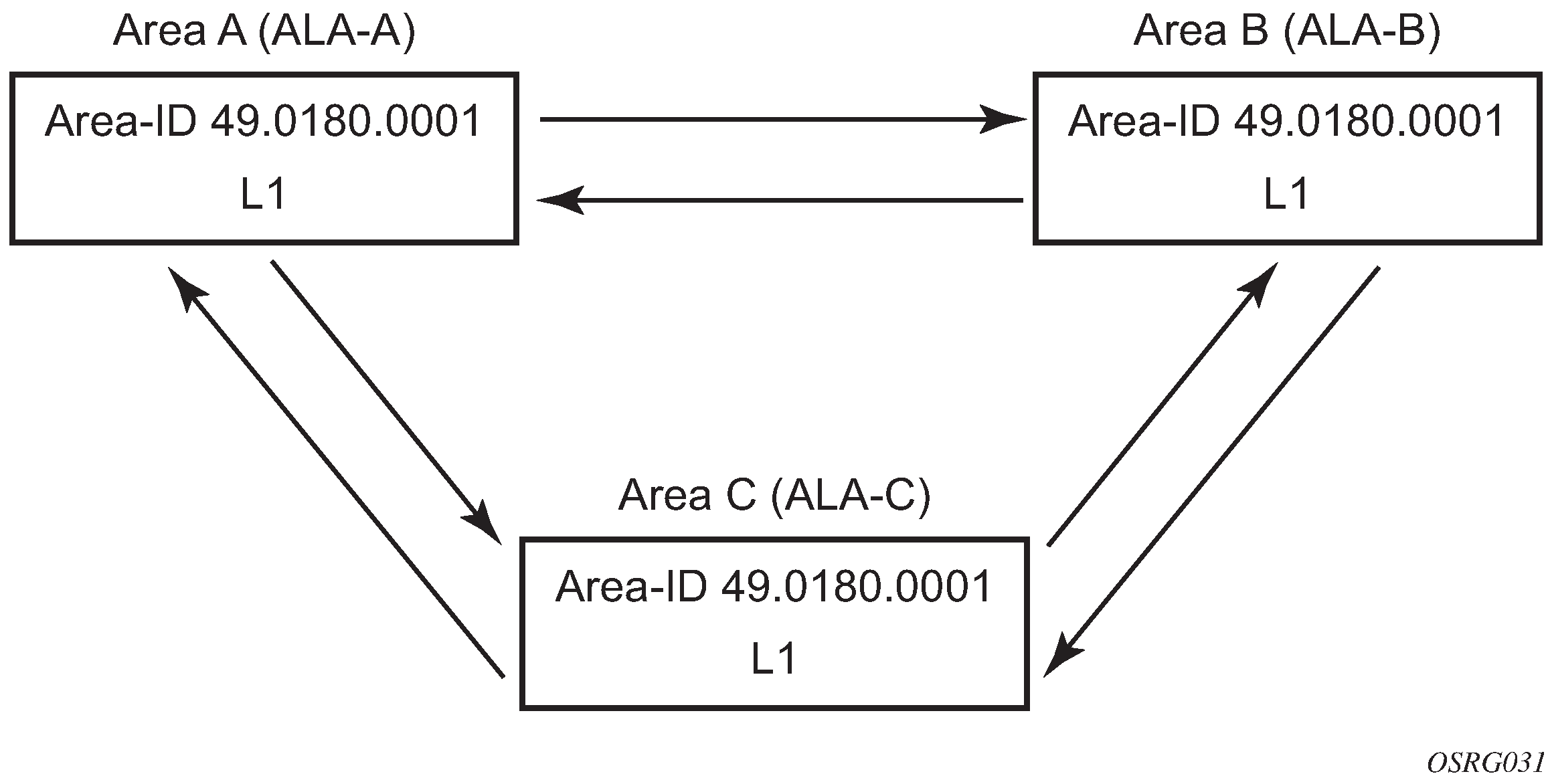
The following example displays the command usage to configure a level 1 area.
A:ALA-A>config>router# isis
A:ALA-A>config>router>isis# area-id 47.0001
A:ALA-A>config>router>isis# level-capability level-1
A:ALA-A>config>router>isis# interface system
A:ALA-A>config>router>isis>if# exit
A:ALA-A>config>router>isis# interface A-B
A:ALA-A>config>router>isis>if# exit
A:ALA-A>config>router>isis# interface A-C
A:ALA-A>config>router>isis>if# exit
A:ALA-A>config>router>isis#

A:ALA-B>config>router# isis
A:ALA-B>config>router>isis# area-id 47.0001
A:ALA-B>config>router>isis# level-capability level-1
A:ALA-B>config>router>isis# interface system
A:ALA-B>config>router>isis>if# exit
A:ALA-B>config>router>isis# interface B-A
A:ALA-B>config>router>isis>if# exit
A:ALA-B>config>router>isis# interface B-C
A:ALA-B>config>router>isis>if# exit
A:ALA-B>config>router>isis#

A:ALA-C>config>router# isis
A:ALA-C>config>router>isis# area-id 47.0001
A:ALA-C>config>router>isis# level-capability level-1
A:ALA-C>config>router>isis# interface system
A:ALA-C>config>router>isis>if# exit
A:ALA-C>config>router>isis# interface "C-A"
A:ALA-C>config>router>isis>if# exit
A:ALA-C>config>router>isis# interface "C-B"
A:ALA-C>config>router>isis>if# exit


A:ALA-A>config>router>isis# info
----------------------------------------------
        level-capability level-1
        area-id 49.0180.0001
        interface "system"
        exit
        interface "A-B"
        exit
        interface "A-C"
        exit
----------------------------------------------
A:ALA-A>config>router>isis#

A:ALA-B>config>router>isis# info
----------------------------------------------
        level-capability level-1
        area-id 49.0180.0001
        interface "system"
        exit
        interface "B-A"
        exit
        interface "B-C"
        exit
----------------------------------------------
A:ALA-B>config>router>isis#

A:ALA-C>config>router>isis# info
#------------------------------------------
echo "ISIS"
----------------------------------------------
        level-capability level-1
        area-id 49.0180.0001
        interface "system"
        exit
        interface "C-A"
        exit
        interface "C-B"
        exit
----------------------------------------------
A:ALA-C>config>router>isis#
Modifying a router’s level capability
In the previous example, ALA-A, ALA-B, and ALA-C are configured as level 1 systems. Level 1 systems communicate with other level 1 systems in the same area. In this example, ALA-A is modified to set the level capability to level 1/2, as shown in Configuring a level 1/2 area. Now, the level 1 systems in the area with NET 47.0001 forward PDUs to ALA-A for destinations that are not in the local area.
The following example displays the command usage to configure a level 1/2 system.
A:ALA-A>config>router# isis
A:ALA-A>config>router>isis# level-capability level-1/2
Configuring IS-IS link groups
IS-IS Link-Groups allows the creation of an administrative grouping of multiple IS-IS member interfaces that should be treated as a common group for ECMP purposes. If the number of operational links in the link-group drops below the operational-member value, then all links associated with that IS-IS link group will have their interface metric increased by the configured offset amounts. As a result, IS-IS will then try to reroute traffic over lower cost paths.
After it is triggered, the higher metric will not be reset to the originally configured IS-IS interface metric values until the number of active interfaces in the link bundle reaches the configured revertive threshold (revert-members).
Prerequisite are the following:
one or more interface members
a configured operational-member (oper-members) value
a configured revertive-member (revert-members) value
configured offset values for the appropriate address families
IS-IS configuration management tasks
This section discusses IS-IS configuration management tasks.
Disabling IS-IS
The shutdown command disables the IS-IS protocol instance on the router. The configuration settings are not changed, reset, or removed.
To disable IS-IS on a router, enter the following commands:
config>router# isis
    shutdown
Removing IS-IS
The no isis command deletes the IS-IS protocol instance. The IS-IS configuration reverts to the default settings.
To remove the IS-IS configuration enter the following commands:
config>router#
    no isis
Modifying global IS-IS parameters
You can modify, disable, or remove global IS-IS parameters without shutting down entities. Changes take effect immediately. Modifying the level capability on the global level causes the IS-IS protocol to restart.
The following example displays command usage to modify various parameters.
Example
config>router>isis# overload timeout 500
config>router>isis# level-capability level-1/2
config>router>isis# no authentication-check
config>router>isis# authentication-key secretkey
The following example displays the global modifications.
A:ALA-A>config>router>isis# info
----------------------------------------------
        area-id 49.0180.0001
        area-id 49.0180.0002
        area-id 49.0180.0003
        authentication-key "//oZrvtvFPn06S42lRIJsE" hash
        authentication-type password
        no authentication-check
        overload timeout 500 on-boot
        level 1
            wide-metrics-only
        exit
        level 2
            wide-metrics-only
        exit
        interface "system"
        exit
        interface "ALA-1-2"
            level-capability level-2
        exit
        interface "ALA-1-3"
            level-capability level-1
            interface-type point-to-point
        exit
        interface "ALA-1-5"
            level-capability level-1
            interface-type point-to-point
        exit
        interface "to-103"
        exit
        interface "A-B"
        exit
        interface "A-C"
        exit
----------------------------------------------
A:ALA-A>config>router>isis#
Modifying IS-IS interface parameters
You can modify, disable, or remove interface-level IS-IS parameters without shutting down entities. Changes take effect immediately. Modifying the level capability on the interface causes the IS-IS protocol on the interface to restart.
To remove an interface, issue the no interface ip-int-name command. To disable an interface, issue the shutdown command in the interface context.
The following example displays interface IS-IS modification command usage. For specific interface configuration and modification examples also see, Configuring a level 1 area and Modifying a router’s level capability.
Example
config>router# isis
config>router>isis# interface ALA-1-3
config>router>isis>if# passive
config>router>isis>if# exit
config>router>isis# interface to-103
config>router>isis>if# hello-authentication-type message-digest
config>router>isis>if# hello-authentication-key secretkey
config>router>isis>if# exit
The following example displays the modified interface parameters.
A:ALA-A>config>router>isis# info
----------------------------------------------
        area-id 49.0180.0001
        area-id 49.0180.0002
        area-id 49.0180.0003
        authentication-key "//oZrvtvFPn06S42lRIJsE" hash
        authentication-type password
        no authentication-check
        overload timeout 500 on-boot
        level 1
            wide-metrics-only
        exit
        level 2
            wide-metrics-only
        exit
        interface "system"
        exit
        interface "ALA-1-2"
            level-capability level-2
        exit
        interface "ALA-1-3"
            level-capability level-1
            interface-type point-to-point
            passive
        exit
        interface "ALA-1-5"
            level-capability level-1
            interface-type point-to-point
        exit
        interface "to-103"
            hello-authentication-key "DvR3l264KQ6vXMTvbAZ1mE" hash
            hello-authentication-type message-digest
        exit
        interface "A-B"
        exit
----------------------------------------------
A:ALA-A>config>router>isis#
Configuring authentication using keychains
The use of authentication mechanism is recommended to protect against malicious attack on the communications between routing protocol neighbors. These attacks could aim to either disrupt communications or to inject incorrect routing information into the systems routing table. The use of authentication keys can help to protect the routing protocols from these types of attacks. In addition, the use of authentication keychains provides the ability to configure authentication keys and make changes to them without affecting the state of the routing protocol adjacencies.
To configure the use of an authentication keychain within IS-IS, use the following steps.
Configure an authentication keychain within the config>system>security context. The configured keychain must include at least on valid key entry, using a valid authentication algorithm for the IS-IS protocol.
Associate the configure authentication keychain with IS-IS. Authentication keychains can be used to specify the authentication at the IS-IS global, and level context as well as for hello authentication at the interface and interface-level context.
The association of the authentication keychain is established through the auth-keychain keychain-name command at the global and level context. The hello authentication association is established through the hello-auth-keychain keychain-name command.
For a key entry to be valid, it must include a valid key, the current system clock value must be within the begin and end time of the key entry, and the algorithm specified in the key entry must be supported by the IS-IS protocol.
The IS-IS protocol supports the following algorithms:
clear text password (RFC 5304 and RFC 5310 formats)
HMAC-MD5 (RFC 5304 and RFC 5310 formats)
HMAC-SHA-1 (RFC 5310 format)
HMAC-SHA-256 (RFC 5310 format)
The IS-IS key entry may also include the option parameter to determine how the IS-IS protocol encodes the authentication signature. The value of basic results in the use of RFC 5304 format. The default or a value of isis-enhanced results in using the RFC 5310 format.
The error handling is described below.
If a keychain exists but there are no active key entries with an authentication type that is valid for the associated protocol then inbound protocol packets are not authenticated and discarded and no outbound protocol packets should be sent.
If keychain exists, but the last key entry has expired, a log entry is raised indicating that all keychain entries have expired. The IS-IS protocol requires that the protocol not revert to an unauthenticated state and requires that the old key is not to be used, therefore, after the last key has expired, all traffic is discarded.
Configuring leaking
IS-IS allows a two-level hierarchy to route PDUs. Level 1 areas can be interconnected by a contiguous level 2 backbone. The level 1 link-state database contains information only about that area. The level 2 link-state database contains information about the level 2 system and each of the level 1 systems in the area. A level 1/2 router contains information about both level 1 and level 2 databases. A level 1/2 router advertises information about its level 1 area toward the other level 1/2 or level 2 (only) routers.
Packets with destinations outside the level 1 area are forwarded toward the closest level 1/2 router which, in turn, forwards the packets to the destination area.
Sometimes, the shortest path to an outside destination is not through the closest level 1/2 router, or, the only level 1/2 system to forward packets out of an area is not operational. Route leaking provides a mechanism to leak level 2 information to level 1 systems to provide routing information about inter-area routes. Then, a level 1 router has more options to forward packets.
Configure a route policy to leak routers from level 2 into level 1 areas in the config>router>policy-options>policy-statement context.
The following example shows the command usage to configure prefix list and policy statement parameters in the config>router context.
config>router>policy-options# prefix-list  loops
..>policy-options>prefix-list# prefix 10.1.1.0/24 longer
..>policy-options>prefix-list# exit
..>policy-options# policy-statement leak
..>policy-options>policy-statement# entry 10
..>policy-options>policy-statement>entry# from
..>policy-options>policy-statement>entry>from# prefix-list loops
..>policy-options>policy-statement>entry>from# level 2
..>policy-options>policy-statement>entry>from# exit
..>policy-options>policy-statement>entry# to
..>policy-options>policy-statement>entry>to# level 1
..>policy-options>policy-statement>entry>to# exit
..>policy-options>policy-statement>entry# action accept
..>policy-options>policy-statement>entry>action# exit
..>policy-options>policy-statement>entry# exit
..>policy-options>policy-statement#exit
..>policy-options# commit
..>policy-options#
A:ALA-A>config>router>policy-options# info
----------------------------------------------
            prefix-list "loops"
                    prefix 10.1.1.0/24 longer
            exit
            policy-statement "leak"
                entry 10
                    from
                        prefix-list "loop"
                        level 2
                    exit
                    to
                        level 1
                    exit
                    action accept
                    exit
                exit
            exit
----------------------------------------------
A:ALA-A>config>router>policy-options#
Next, apply the policy to leak routes from level 2 info level 1 systems on ALA-A.
config>router#isis
config>router>isis# export leak

A:ALA-A>config>router>isis# info
----------------------------------------------
        area-id 49.0180.0001
        area-id 49.0180.0002
        area-id 49.0180.0003
        authentication-key "//oZrvtvFPn06S42lRIJsE" hash
        authentication-type password
        no authentication-check
        export "leak"
...
----------------------------------------------
A:ALA-A>config>router>isis#
After the policy is applied, create a policy to redistribute external IS-IS routes from level 1 systems into the level 2 backbone (see Redistributing external IS-IS routers). In the config>router context, configure the following policy statement parameters:
config>router>policy-options# begin
..>policy-options# policy-statement "isis-ext"
..>policy-options>policy-statement# entry 10
..>policy-options>policy-statement>entry$ from
..>policy-options>policy-statement>entry>from$ external
..>policy-options>policy-statement>entry>from# exit
..>policy-options>policy-statement>entry# to
..>policy-options>policy-statement>entry>to$ level 2
..>policy-options>policy-statement>entry>to# exit
..>policy-options>policy-statement>entry# action accept
..>policy-options>policy-statement>entry>action# exit
..>policy-options>policy-statement>entry#  exit
..>policy-options>policy-statement# exit
..>policy-options# commit
A:ALA-A>config>router>policy-options# info
----------------------------------------------
            prefix-list "loops"
                    prefix 10.1.1.0/24 longer
            exit
            policy-statement "leak"
                entry 10
                    from
                        prefix-list "loop"
                        level 2
                    exit
                    to
                        level 1
                    exit
                    action accept
                    exit
                exit
            exit
            policy-statement "isis-ext"
                entry 10
                    from
                        external
                    exit
                    to
                        level 2
                    exit
                    action accept
                    exit
                exit
            exit
----------------------------------------------
A:ALA-A>config>router>policy-options#
Redistributing external IS-IS routers
IS-IS does not redistribute level 1 external routes into level 2 by default. You must explicitly apply the policy to redistribute external IS-IS routes. Policies are created in the config>router>policy-options context. See Route policies for more information.
The following example displays the policy statement configuration.
config>router>policy-options# info
----------------------------------------------
            prefix-list "loops"
                    prefix 10.1.1.0/24 longer
            exit
            policy-statement "leak"
                entry 10
                    from
                        prefix-list "loop"
                        level 2
                    exit
                    to
                        level 1
                    exit
                    action accept
                    exit
                exit
            exit
            policy-statement "isis-ext"
                entry 10
                    from
                        external
                    exit
                    to
                        level 2
                    exit
                    action accept
                    exit
                exit
            exit
----------------------------------------------
config>router>policy-options#
Specifying MAC addresses for all IS-IS routers
Specify the MAC address to use for all L1 or L2 IS-IS routers. The following example shows how to specify all L1 routers.
Example
- all-l1isis 01-80-C2-00-00-14You can also specify the MAC address for all L2 IS-IS routers by using the all-l2isis command.