OSPF
Configuring OSPF
Open Shortest Path First (OSPF) is a hierarchical link state protocol. OSPF is an interior gateway protocol (IGP) used within large autonomous systems (ASs). OSPF routers exchange state, cost, and other relevant interface information with neighbors. The information exchange enables all participating routers to establish a network topology map. Each router applies the Dijkstra algorithm to calculate the shortest path to each destination in the network. The resulting OSPF forwarding table is submitted to the routing table manager to calculate the routing table.
When a router is started with OSPF configured, OSPF, along with the routing-protocol data structures, is initialized and waits for indications from lower-layer protocols that its interfaces are functional. Nokia’s implementation of OSPF conforms to OSPF Version 2 specifications presented in RFC 2328, OSPF Version 2 and OSPF Version 3 specifications presented in RFC 2740, OSPF for IPv6. Routers running OSPF can be enabled with minimal configuration. All default and command parameters can be modified.
Changes between OSPF for IPv4 and OSPF3 for IPv6 include the following:
Addressing semantics have been removed from OSPF packets and the basic link-state advertisements (LSAs). New LSAs have been created to carry IPv6 addresses and prefixes.
OSPF3 runs on a per-link basis, instead of on a per-IP-subnet basis.
Flooding scope for LSAs has been generalized.
Unlike OSPFv2, OSPFv3 authentication relies on IPV6's authentication header and encapsulating security payload.
Most packets in OSPF for IPv6 are almost as compact as those in OSPF for IPv4, even with the larger IPv6 addresses.
Most field and packet-size limitations present in OSPF for IPv4 have been relaxed.
Option handling has been made more flexible.
Key OSPF features are:
backbone areas
stub areas
not-so-stubby areas (NSSAs)
virtual links
authentication
route redistribution
routing interface parameters
OSPF-TE extensions (Nokia’s implementation allows MPLS fast reroute)
OSPF areas
The hierarchical design of OSPF allows a collection of networks to be grouped into a logical area. An area’s topology is concealed from the rest of the AS which significantly reduces OSPF protocol traffic. With the correct network design and area route aggregation, the size of the route-table can be drastically reduced which results in decreased OSPF route calculation time and topological database size.
Routing in the AS takes place on two levels, depending on whether the source and destination of a packet reside in the same area (intra-area routing) or different areas (inter-area routing). In intra-area routing, the packet is routed solely on information obtained within the area; no routing information obtained from outside the area is used.
Routers that belong to more than one area are called area border routers (ABRs). An ABR maintains a separate topological database for each area it is connected to. Every router that belongs to the same area has an identical topological database for that area.
Backbone area
The OSPF backbone area, area 0.0.0.0, must be contiguous and all other areas must be connected to the backbone area. The backbone distributes routing information between areas. If it is not practical to connect an area to the backbone (see area 0.0.0.5 in Backbone area) then the ABRs (such as routers Y and Z) must be connected via a virtual link. The two ABRs form a point-to-point-like adjacency across the transit area (see area 0.0.0.4).
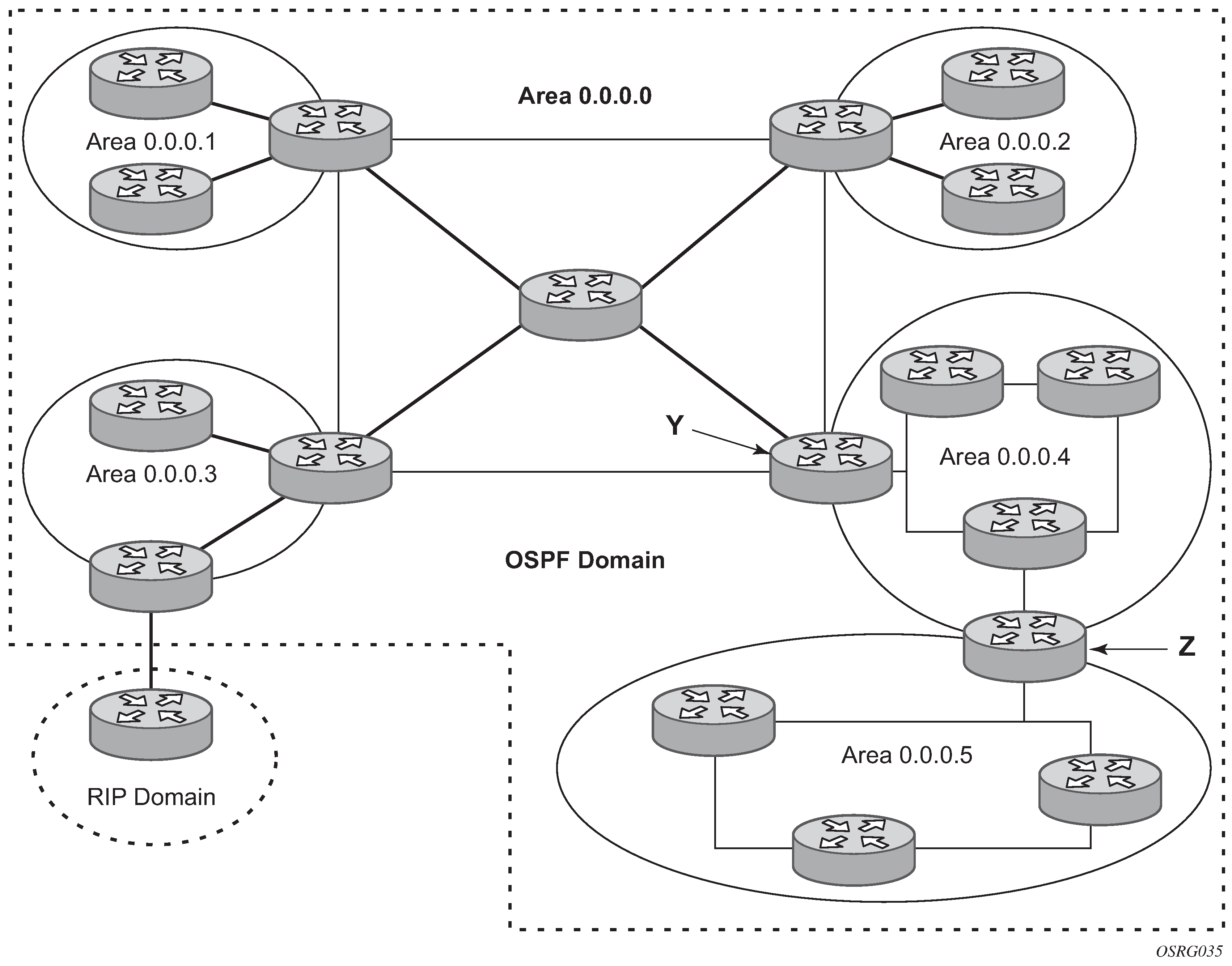
Stub area
A stub area is a designated area that does not allow external route advertisements. Routers in a stub area do not maintain external routes. A single default route to an ABR replaces all external routes. This OSPF implementation supports the optional summary route (type-3) advertisement suppression from other areas into a stub area. This feature further reduces topological database sizes and OSPF protocol traffic, memory usage, and CPU route calculation time.
In Backbone area, areas 0.0.0.1, 0.0.0.2 and 0.0.0.5 could be configured as stub areas. A stub area cannot be designated as the transit area of a virtual link and a stub area cannot contain an AS boundary router. An AS boundary router exchanges routing information with routers in other ASs.
Not-so-stubby area
Another OSPF area type is called a Not-So-Stubby area (NSSA). NSSAs are similar to stub areas in that no external routes are imported into the area from other OSPF areas. External routes learned by OSPF routers in the NSSA area are advertised as type-7 LSAs within the NSSA area and are translated by ABRs into type-5 external route advertisements for distribution into other areas of the OSPF domain. An NSSA area cannot be designated as the transit area of a virtual link.
In Backbone area, area 0.0.0.3 could be configured as a NSSA area.
OSPF super backbone
The 77x0 PE routers have implemented a version of the BGP/OSPF interaction procedures as defined in RFC 4577, OSPF as the Provider/Customer Edge Protocol for BGP/MPLS IP Virtual Private Networks (VPNs). Features included in this RFC includes:
loop prevention
handling LSAs received from the CE
sham links
managing VPN-IPv4 routes received by BGP
VPRN routes can be distributed among the PE routers by BGP. If the PE uses OSPF to distribute routes to the CE router, the standard procedures governing BGP/OSPF interactions causes routes from one site to be delivered to another in type 5 LSAs, as AS-external routes.
The MPLS VPN super backbone behaves like an additional layer of hierarchy in OSPF. The PE-routers that connect the respective OSPF areas to the super backbone function as OSPF Area Border Routers (ABR) in the OSPF areas to which they are attached. To achieve full compatibility, they can also behave as AS Boundary Routers (ASBR) in non-stub areas.
The PE-routers insert inter-area routes from other areas into the area where the CE-router is present. The CE-routers are not involved at any level, nor are they aware of the super backbone or of other OSPF areas present beyond the MPLS VPN super backbone.
The CE always assumes the PE is an ABR:
If the CE is in the backbone, then the CE router assumes that the PE is an ABR linking one or more areas to the backbone.
If the CE in not in the backbone, then the CE believes that the backbone is on the other side of the PE.
As such, the super backbone looks like another area to the CE.
Figure 2. PEs connected to an MPLS-VPN super backbone 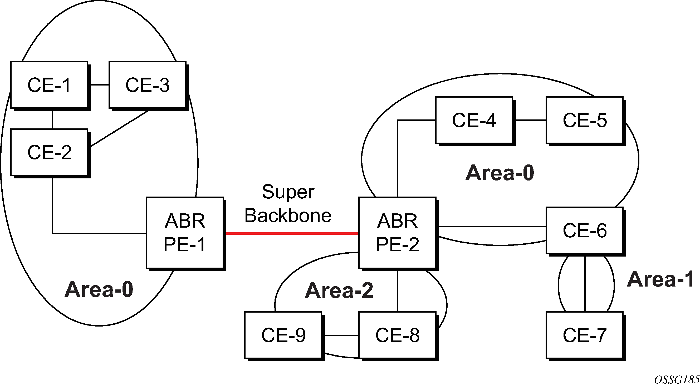
In PEs connected to an MPLS-VPN super backbone, the PEs are connected to the MPLS-VPN super backbone. To be able to distinguish if two OSPF instances are in fact the same and require Type 3 LSAs to be generated, or are two separate routing instances where type 5 external LSAs need to be generated, the concept of a domain-id is introduced.
The domain ID is carried with the MP-BGP update and indicates the source OSPF Domain. When the routes are being redistributed into the same OSPF Domain, the concepts of super backbone described above apply and Type 3 LSAs are generated. If the OSPF domain does not match, then the route type is external.
Configuring the super backbone (not the sham links) makes all destinations learned by PEs with matching domain IDs inter-area routes.
When configuring sham links, these links become intra-area routes if they are present in the same area.
Sham links
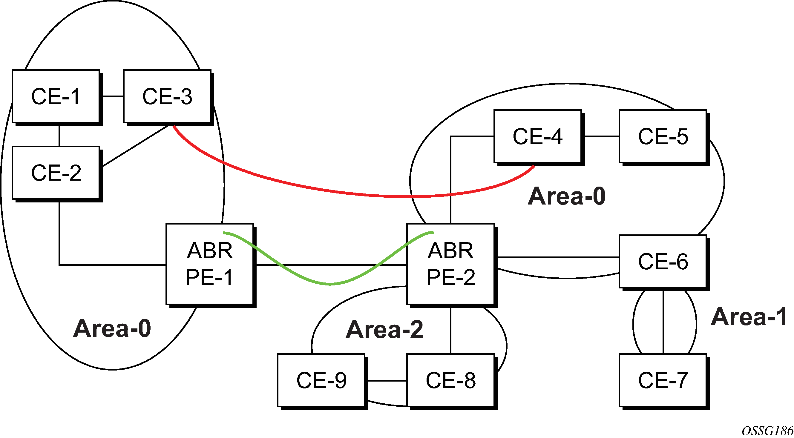
In Sham links, the red link between CE-3 and CE-4 could be a low speed OC-3/STM-1 link, but because it establishes an intra-area route connection between the CE-3 and CE-4, the potentially high-speed PE-1 to PE-2 connection is not used. Even with a super backbone configuration, it is regarded as an inter-area connection.
The establishment of the (green) sham-link is also constructed as an intra-area link between PE routers, a normal OSPF adjacency is formed and the link-state database is exchanged across the MPLS-VPRN. As a result, the needed intra-area connectivity is created, at this time the cost of the green and red links can be managed such that the red link becomes a standby link only in case the VPN fails.
As the sham-link forms an adjacency over the MPLS-VPRN backbone network, be aware that when protocol-protection is enabled in the config>sys>security>cpu-protection>protocol-protection context, the operator must explicit allow the OSPF packets to be received over the backbone network. This performed using the allow-sham-links parameter of the protocol-protection command.
Implementing the OSPF super backbone
With the OSPF super backbone architecture, the continuity of OSPF routing is preserved.
The OSPF intra-area LSAs (type-1 and type-2) advertised bye the CE are inserted into the MPLS-VPRN super backbone by redistributing the OSPF route into MP-BGP by the PE adjacent to the CE.
The MP-BGP route is propagated to other PE-routers and inserted as an OSPF route into other OSPF areas. Considering the PEs across the super backbone always act as ABRs they generate inter area route OSPF summary LSAs, Type 3.
The inter-area route can now be propagated into other OSPF areas by other customer owned ABRs within the customer site.
Customer Area 0 (backbone) routes when carried across the MPLS-VPRN using MPBGP appear as Type 3 LSAs even if the customer area remains area 0 (backbone).
A BGP extended community (OSPF domain ID) provides the source domain of the route. This domain ID is not carried by OSPF but carried by MP-BGP as an extended community attribute.
If the configured extended community value matches the receiving OSPF domain, then the OSPF super backbone is implemented.
From a BGP perspective, the cost is copied into the MED attribute.
Loop avoidance
If a route sent from a PE router to a CE router could then be received by another PE router from one of its own CE routers then it is possible for routing loops to occur. RFC 4577 specifies several methods of loop avoidance.
DN-BIT
When a Type 3 LSA is sent from a PE router to a CE router, the DN bit in the LSA options field is set. This is used to ensure that if any CE router sends this Type 3 LSA to a PE router, the PE router does not redistribute it further.
When a PE router needs to distribute to a CE router a route that comes from a site outside the latter's OSPF domain, the PE router presents itself as an ASBR (Autonomous System Border Router), and distributes the route in a type 5 LSA. The DN bit must be set in these LSAs to ensure that they are ignored by any other PE routers that receive them.
DN-BIT loop avoidance is also supported.
Route tag
If a particular VRF in a PE is associated with an instance of OSPF, then by default it is configured with a special OSPF route tag value called the VPN route tag. This route tag is included in the Type 5 LSAs that the PE originates and sends to any of the attached CEs. The configuration and inclusion of the VPN Route Tag is required for backward compatibility with deployed implementations that do not set the DN bit in Type 5 LSAs.
Sham links
A sham link is only required if a backdoor link (shown as the red link in Sham links) is present, otherwise configuring an OSPF super backbone will probably suffice.
OSPFv3 authentication
OSPFv3 authentication requires IPv6 IPsec and supports the following:
IPsec transport mode
AH and ESP
manual keyed IPsec Security Association (SA)
authentication Algorithms MD5 and SHA1
To pass OSPFv3 authentication, OSPFv3 peers must have matching inbound and outbound SAs configured using the same SA parameters (SPI, keys, and so on). The implementation must allow the use of one SA for both inbound and outbound directions.
This feature is supported on IES and VPRN interfaces as well as on virtual links.
The re-keying procedure defined in RFC 4552,Authentication/Confidentiality for OSPFv3, supports the following.
For every router on the link, create an additional inbound SA for the interface being re-keyed using a new SPI and the new key.
For every router on the link, replace the original outbound SA with one using the new SPI and key values. The SA replacement operation should be atomic with respect to sending OSPFv3 packet on the link so that no OSPFv3 packets are sent without authentication or encryption.
For every router on the link, remove the original inbound SA.
The key rollover procedure automatically starts when the operator changes the configuration of the inbound static-sa or bidirectional static-sa under an interface or virtual link. Within the KeyRolloverInterval time period, OSPF3 accepts packets with both the previous inbound static-sa and the new inbound static-sa, and the previous outbound static-sa should continue to be used. When the timer expires, OSPF3 only accepts packets with the new inbound static-sa and for outgoing OSPF3 packets, the new outbound static-sa is used instead.
OSPF graceful restart helper
Both OSPFv2 and OSPFv3 support the graceful restart helper function which provides an OSPF neighbor a grace period during a control plane restart to minimize service disruption. When the control plane of a GR-capable router fails or restarts, the neighboring routers supporting the graceful restart helper mode (GR helpers) temporarily preserve OSPF forwarding information. Traffic continues to be forwarded to the restarting router using the last known forwarding tables. If the control plane of the restarting router comes back up within the grace period, the restarting router resumes normal OSPF operation. If the grace period expires, then the restarting router is presumed to be inactive and the OSPF topology is recalculated to route traffic around the failure.
BFD interaction with graceful restart
If the SR OS router is providing a grace period to an adjacent neighbor and the BFD session associated with that neighbor fails, the behavior is determined by the C-bit values sent by each neighbor as follows.
If both BFD endpoints have set their C-bit value, then the graceful restart helper mode is canceled and any routes from that neighbor that are marked as stale are removed from the forwarding table.
If either of the BFD endpoints has not set their C-bit value, then the graceful restart helper mode continues.
OSPFv3 graceful restart helper
This feature extends the graceful restart helper function supported under other protocols to OSPFv3.
The primary difference between graceful restart helper for OSPFv2 and OSPFv3 is in OSPFv3 a different grace-LSA format is used.
As SR OS platforms can support a fully non-stop routing model for control plane high availability, SR OSs have no need for graceful restart as defined by the IETF in various RFCs for each routing protocol. However, since the router does need to coexist in multi-vendor networks and other routers do not always support a true non-stop routing model with stateful failover between routing control planes, there is a need to support a graceful restart helper function.
Graceful restart helper mode allows SR OS-based systems to provide a grace period to other routers which have requested it, during which the SR OS systems continue to use routes authored by or transiting the router requesting the grace period. This is typically used when another router is rebooting the control plane but the forwarding plane is expected to continue to forward traffic based on the previously available FIB.
The format of the graceful OSPF restart (GRACE) LSA format is:
        0                   1                   2                   3
        0 1 2 3 4 5 6 7 8 9 0 1 2 3 4 5 6 7 8 9 0 1 2 3 4 5 6 7 8 9 0 1
       +-+-+-+-+-+-+-+-+-+-+-+-+-+-+-+-+-+-+-+-+-+-+-+-+-+-+-+-+-+-+-+-+
       |           LS age              |0|0|0|          11             |
       +-+-+-+-+-+-+-+-+-+-+-+-+-+-+-+-+-+-+-+-+-+-+-+-+-+-+-+-+-+-+-+-+
       |                       Link State ID                           |
       +-+-+-+-+-+-+-+-+-+-+-+-+-+-+-+-+-+-+-+-+-+-+-+-+-+-+-+-+-+-+-+-+
       |                    Advertising Router                         |
       +-+-+-+-+-+-+-+-+-+-+-+-+-+-+-+-+-+-+-+-+-+-+-+-+-+-+-+-+-+-+-+-+
       |                    LS sequence number                         |
       +-+-+-+-+-+-+-+-+-+-+-+-+-+-+-+-+-+-+-+-+-+-+-+-+-+-+-+-+-+-+-+-+
       |        LS checksum            |            Length             |
       +-+-+-+-+-+-+-+-+-+-+-+-+-+-+-+-+-+-+-+-+-+-+-+-+-+-+-+-+-+-+-+-+
       |                                                               |
       +-                            TLVs                             -+
       |                             ...                               |
For more information, see section 2.2 of RFC 5187, OSPFv3 Graceful Restart.
The Link State ID of a grace-LSA in OSPFv3 is the Interface ID of the interface originating the LSA.
The format of each TLV is:
        0                   1                   2                   3
        0 1 2 3 4 5 6 7 8 9 0 1 2 3 4 5 6 7 8 9 0 1 2 3 4 5 6 7 8 9 0 1
       +-+-+-+-+-+-+-+-+-+-+-+-+-+-+-+-+-+-+-+-+-+-+-+-+-+-+-+-+-+-+-+-+
       |              Type             |             Length            |
       +-+-+-+-+-+-+-+-+-+-+-+-+-+-+-+-+-+-+-+-+-+-+-+-+-+-+-+-+-+-+-+-+
       |                            Value...                           |
       +-+-+-+-+-+-+-+-+-+-+-+-+-+-+-+-+-+-+-+-+-+-+-+-+-+-+-+-+-+-+-+-+

                                TLV Format
Grace-LSA TLVs are formatted according to section 2.3.2 of RFC 3630, Traffic Engineering (TE) Extensions to OSPF Version 2. The Grace-LSA TLVs are used to carry the Grace period (type 1) and the reason the router initiated the graceful restart process (type 2).
Other information in RFC 5187 is directed to routers that require the full graceful restart mechanism as they do not support a stateful transition from primary or backup control plane module (CPM).
Virtual links
The backbone area in an OSPF AS must be contiguous and all other areas must be connected to the backbone area. Sometimes, this is not possible. You can use virtual links to connect to the backbone through a non-backbone area.
Backbone area depicts routers Y and Z as the start and end points of the virtual link while area 0.0.0.4 is the transit area. The router must be an ABR to configure virtual links. Virtual links are identified by the router ID of the other endpoint, another ABR. These two endpoint routers must be attached to a common area, called the transit area. The area through which you configure the virtual link must have full routing information.
Transit areas pass traffic from an area adjacent to the backbone or to another area. The traffic does not originate in, nor is it destined for, the transit area. The transit area cannot be a stub area or a NSSA area.
Virtual links are part of the backbone, and behave as if they were unnumbered point-to-point networks between the two routers. A virtual link uses the intra-area routing of its transit area to forward packets. Virtual links are brought up and down through the building of the shortest-path trees for the transit area.
Neighbors and adjacencies
Broadcast and point-to-point networks
A router uses the OSPF Hello protocol to discover neighbors. The router sends hello packets to a multicast address and receives hello packets in return.
In broadcast networks, a designated router and a backup designated router are elected. The designated router is responsible for sending link-state advertisements (LSAs) describing the network, which reduces the amount of network traffic.
The routers attempt to form adjacencies. An adjacency is a relationship formed between a router and the designated or backup designated router. For point-to-point networks, no designated or backup designated router is elected. An adjacency must be formed with the neighbor.
To significantly improve adjacency forming and network convergence, a network should be configured as point-to-point if only two routers are connected, even if the network is a broadcast medium such as Ethernet.
When the link-state databases of two neighbors are synchronized, the routers are considered to be fully adjacent. When adjacencies are established, pairs of adjacent routers synchronize their topological databases. Not every neighboring router forms an adjacency. Routing protocol updates are only sent to and received from adjacencies. Routers that do not become fully adjacent remain in the two-way neighbor state.
Non-broadcast multi-access networks
In addition to point-to-point and broadcast networks, OSPF can operate in non-broadcast multi-access (NBMA) mode.
An NBMA segment emulates the function of a broadcast network. Every router on the segment must be configured with the IP addresses of each of its neighbors, and may need to be configured with the MAC address of its neighbor if the network does not support Layer 2 broadcast. OSPF Hello packets are transmitted individually as unicast packets to each adjacent neighbor. Because an NBMA network has no broadcast or multicast capabilities, the routing device cannot discover its neighbors dynamically, so all neighbors must be configured statically.
As in a broadcast network, a designated router and a backup designated router are elected when OSPF is operating in NBMA mode. The designated router is similarly responsible for sending link-state advertisements (LSAs) for the network.
OSPF does not support NBMA interfaces that are part of a multi-area adjacency. An interface can either be in multiple areas or in NBMA mode.
OSPFv3 sends Hello traffic to IPv6 link-local addresses and neighbors must be statically configured using their IPv6 link-local address.
OSPF NBMA is supported on Ethernet ports only.
Link-state advertisements
Link-state advertisements (LSAs) describe the state of a router or network, including router interfaces and adjacency states. Each LSA is flooded throughout an area. The collection of LSAs from all routers and networks form the protocol's topological database.
The distribution of topology database updates take place along adjacencies. A router sends LSAs to advertise its state according to the configured interval and when the router's state changes. These packets include information about the router's adjacencies, which allows detection of non-operational routers.
When a router discovers a routing table change or detects a change in the network, link state information is advertised to other routers to maintain identical routing tables. Router adjacencies are reflected in the contents of its link state advertisements. The relationship between adjacencies and the link states allow the protocol to detect non-operating routers. Link state advertisements flood the area. The flooding mechanism ensures that all routers in an area have the same topological database. The database consists of the collection of LSAs received from each router belonging to the area.
OSPF sends only the part that has changed and only when a change has taken place. From the topological database, each router constructs a tree of shortest paths with itself as root. OSPF distributes routing information between routers belonging to a single AS.
Metrics
In OSPF, all interfaces have a cost value or routing metric used in the OSPF link-state calculation. A metric value is configured based on hop count, bandwidth, or other parameters, to compare different paths through an AS. OSPF uses cost values to determine the best path to a particular destination: the lower the cost value, the more likely the interface will be used to forward data traffic.
Costs are also associated with externally derived routing data, such as those routes learned from the Exterior Gateway Protocol (EGP), like BGP, and is passed transparently throughout the AS. This data is kept separate from the OSPF protocol's link state data. Each external route can be tagged by the advertising router, enabling the passing of detailed information between routers on the boundaries of the AS.
Authentication
All OSPF protocol exchanges can be authenticated. This means that only trusted routers can participate in autonomous system routing. Nokia’s implementation of OSPF supports plain text and Message Digest 5 (MD5) authentication (also called simple password).
MD5 allows an authentication key to be configured per network. Routers in the same routing domain must be configured with the same key. When the MD5 hashing algorithm is used for authentication, MD5 is used to verify data integrity by creating a 128-bit message digest from the data input. It is unique to that data. Nokia’s implementation of MD5 allows the migration of an MD5 key by using a key ID for each unique key.
By default, authentication is not enabled on an interface.
IP subnets
OSPF enables the flexible configuration of IP subnets. Each distributed OSPF route has a destination and mask. A network mask is a 32-bit number that indicates the range of IP addresses residing on a single IP network/subnet. This specification displays network masks as hexadecimal numbers; for example, the network mask for a class C IP network is displayed as 0xffffff00. Such a mask is often displayed as 255.255.255.0.
Two different subnets with same IP network number have different masks, called variable length subnets. A packet is routed to the longest or most specific match. Host routes are considered to be subnets whose masks are all ones (0xffffffff).
Preconfiguration recommendations
The router ID must be available before configuring OSPF. The router ID is a 32-bit number assigned to each router running OSPF. This number uniquely identifies the router within an AS. OSPF routers use the router IDs of the neighbor routers to establish adjacencies. Neighbor IDs are learned when Hello packets are received from the neighbor.
Before configuring OSPF parameters, ensure that the router ID is derived by one of the following methods.
Define the value in the config>router router-id context.
Define the system interface in the config>router>interface ip-int-name context (used if the router ID is not specified in the config>router router-id context).
A system interface must have an IP address with a 32-bit subnet mask. The system interface is used as the router identifier by higher-level protocols such as OSPF and IS-IS. The system interface is assigned during the primary router configuration process when the interface is created in the logical IP interface context.
If you do not specify a router ID, then the last four bytes of the MAC address are used.
Multiple OSPF instances
The main route table manager (RTM) can create multiple instances of OSPF by extending the current creation of an instance. A specific interface can only be a member of a single OSPF instance. When an interface is configured in a specified domain and needs to be moved to another domain the interface must first be removed from the old instance and re-created in the new instance.
Route export policies for OSPF
Route policies allow specification of the source OSPF process ID in the from and to parameters in the config>router>policy-options>policy-statement>entry>from context, for example from protocol ospf instance-id.
If an instance-id is specified, only routes installed by that instance are picked up for announcement. If no instance-id is specified, then only routes installed by the base instance are announced. The all keyword announces routes installed by all instances of OSPF.
When announcing internal (intra/inter-area) OSPF routes from another process, the default type should be type-1, and metric set to the route metric in RTM. For AS-external routes, by default the route type (type-1/2) should be preserved in the originated LSA, and metric set to the route metric in RTM. By default, the tag value should be preserved when an external OSPF route is announced by another process. All these can be changed with explicit action statements.
Export policy should allow match criteria based on the OSPF route hierarchy (for example, only intra-area, only inter-area, only external, only internal (intra/inter-area)). There must also be a possibility to filter based on existing tag values.
Preventing route redistribution loops
The legacy method for this was to assign a tag value to each OSPF process and mark each external route originated within that domain with that value. However, since the tag value must be preserved throughout different OSPF domains, this only catches loops that go back to the originating domain and not where looping occurs in a remote set of domains. To prevent this type of loop, the route propagation information in the LSA must be accumulative. The following method has been implemented.
The OSPF tag field in the AS-external LSAs is treated as a bit mask, instead of a scalar value. In other words, each bit in the tag value can be independently checked, set or reset as part of the routing policy.
When a set of OSPF domains are provisioned in a network, each domain is assigned a specific bit value in the 32-bit tag mask. When an external route is originated by an ASBR using an internal OSPF route in a specified domain, a corresponding bit is set in the AS-external LSA. As the route gets redistributed from one domain to another, more bits are set in the tag mask, each corresponding to the OSPF domain the route visited. Route redistribution looping is prevented by checking the corresponding bit as part of the export policy. If the bit corresponding to the announcing OSPF process is already set, the route is not exported there.
From the CLI perspective, this involves adding a set of from tag and action tag commands that allow for bit operations.
Multi-address support for OSPFv3
While OSPFv3 was originally designed to carry only IPv6 routing information, the protocol has been extended to add support for other address families through work within the IETF (RFC 5838). These extensions within SR OS allow separate OSPFv3 instances to be used for IPv6 or IPv4 routing information.
To configure an OSPFv3 instance to distribute IPv4 routing information, a specific OSPFv3 instance must be configured using an instance ID within the range specified by the RFC. For unicast IPv4, the range is 64 to 95.
The following shows the basic configuration steps needed to create the OSPFv3 (ospf3) instance to carry IPv4 routing information. When the instance is created, the OSPFv3 instance can be configured as needed for the associated network areas, interfaces, and other protocol attributes as you would for OSPFv2.
Example:
config
  router
    ospf3 64 10.20.1.3
IP Fast-Reroute for OSPF and IS-IS prefixes
The IP Fast-Reroute (IP FRR) feature supports the use of the Loop-Free Alternate (LFA) backup next-hop to forward packets of IP prefixes when the primary next hop is not available. This allows a node to resume forwarding IP packets to a destination prefix without waiting for the routing convergence.
When any of the following events occurs, IGP instructs in the fast path the IOM or the forwarding engine to enable the LFA backup next hop.
OSPF/IS-IS interface goes operationally down: physical or local admin shutdown.
Timeout of a BFD session to a next hop when BFD is enabled on the OSPF/IS-IS interface.
IP FRR is supported on IPv4 and IPv6 OSPF/IS-IS prefixes forwarded in the base router instance to a network IP interface or to an IES SAP interface or spoke interface. It is also supported for VPRN VPN-IPv4 OSPF prefixes and VPN-IPv6 OSPF prefixes forwarded to a VPRN SAP interface or spoke interface.
IP FRR also provides a LFA backup next hop for the destination prefix of a GRE tunnel used in an SDP or in VPRN auto-bind.
The LFA next hop precomputation by IGP is described in RFC 5286 Basic Specification for IP Fast Reroute: Loop-Free Alternates.
IP FRR configuration
First, the user enables LFA computation by SPF under the IS-IS routing protocol level or under the OSPF routing protocol instance level using the following commands:
- classic
CLI
config>router>isis>loopfree-alternates
config>router>ospf>loopfree-alternates
- MD-CLI
configure router isis loopfree-alternate
configure router ospf loopfree-alternate
The preceding commands instruct the IGP SPF to attempt to precompute both a primary next hop and an LFA next hop for every learned prefix. When found, the LFA next hop is populated into the RTM along with the primary next hop for the prefix.
After enabling LFA computation, the user enables IP FRR using the following commands to cause RTM to download to the IOM or the forwarding engine an LFA next hop, when found by SPF, in addition to the primary next hop for each prefix in the FIB.
- classic CLI
config>router>ip-fast-reroute
- MD-CLI
configure routing-options ip-fast-reroute
Reducing the scope of the LFA SPF computation
The user can instruct IGP to not include all interfaces participating in a specific IS-IS level or OSPF area in the SPF LFA computation. This reduces the LFA SPF calculation where it is not needed.
-
classic CLI
config>router>isis>level>loopfree-alternate-exclude
config>router>ospf>area>loopfree-alternate-exclude
-
MD-CLI
configure router isis level loopfree-alternate-exclude
configure router ospf area loopfree-alternate-exclude
The user can also exclude a specific IP interface from the LFA SPF computation by IS-IS or OSPF using the following commands.
-
classic CLI
config>router>isis>interface>loopfree-alternate-exclude
config>router>ospf>area>interface>loopfree-alternate-exclude
-
MD-CLI
configure router isis interface loopfree-alternate exclude
configure router ospf area interface loopfree-alternate exclude
When an interface is excluded from the LFA SPF in IS-IS, it is excluded in both level 1 and level 2. When an interface is excluded from the LFA SPF in OSPF, it is excluded in all areas. However, the preceding OSPF command can only be executed under the area in which the specified interface is primary; when enabled, the interface is excluded in that area and in all other areas where the interface is secondary. If the user attempts to apply it to an area where the interface is secondary, the command fails.
The user can also apply the loopfree-alternate-exclude commands for an OSPF instance within a VPRN service.
-
classic CLI
config>service>vprn>ospf>area>loopfree-alternate-exclude
config>service>vprn>ospf>area>if>loopfree-alternate-exclude
-
MD-CLI
configure service vprn ospf area loopfree-alternate-exclude
configure service vprn ospf area interface loopfree-alternate-exclude
ECMP considerations
When the SPF calculates more than one primary next hop for a prefix, it does not program an LFA next hop. IP prefixes resolve to the multiple primary next hops, providing the required protection.
IP FRR and RSVP shortcut
When both IP FRR and RSVP shortcut (IGP shortcut) and LFA are enabled in IS-IS or OSPF, and IP FRR is also enabled, the following additional IP FRR are supported.
A prefix that is resolved to a direct primary next hop can be backed up by a tunneled LFA next hop.
A prefix that is resolved to a tunneled primary next hop does not have an LFA next hop. It relies on RSVP FRR for protection.
The LFA SPF is extended to use IGP shortcuts as LFA next hops as described in OSPF and IS-IS support for LFA calculation.
IP FRR and BGP next-hop resolution
The LFA backup next-hop can protect the primary next-hop to reach a prefix advertised by a BGP neighbor. The BGP next-hop remains up when the FIB switches from the primary IGP next-hop to the LFA IGP next-hop.
OSPF and IS-IS support for LFA calculation
SPF computation in IS-IS and OSPF is enhanced to compute LFA alternate routes for each learned prefix and populate it in RTM.
The following figure shows a simple network topology with point-to-point (P2P) interfaces and highlights three routes to reach router R5 from router R1.
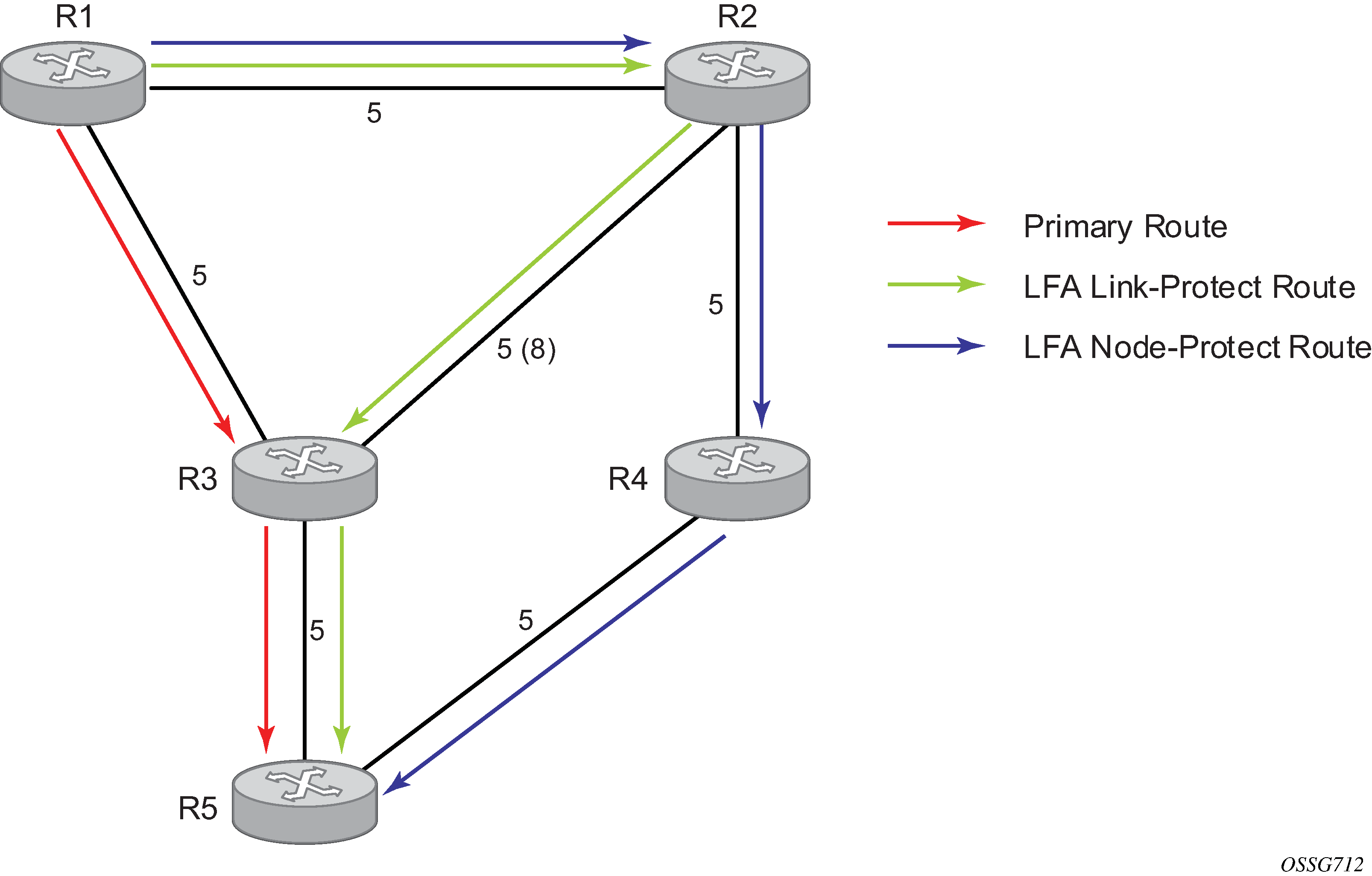
The primary route is via R3. The LFA route via R2 has two equal cost paths to reach R5. The path by way of R3 protects against failure of link R1-R3. R1 computes this route by checking that the cost for R2 to reach R5 by way of R3 is lower than the cost by way of routes R1 and R3. This condition is referred to as the Loop-free Criterion (LFC).
The path by way of R2 and R4 can be used to protect against the failure of router R3. However, with the link R2-R3 metric set to 5, R2 sees the same cost to forward a packet to R5 by way of R3 and R4. Therefore, R1 cannot guarantee that enabling the LFA next-hop R2 protects against R3 node failure. This means that the LFA next-hop R2 provides link protection only for prefix R5. If the metric of link R2-R3 is changed to 8, the LFA next-hop R2 provides node protection since a packet to R5 always goes over R4. That is, it is required that R2 become loop-free with respect to both the source node R1 and the protected node R3.
The following figure shows an example where the primary next hop uses a broadcast interface.
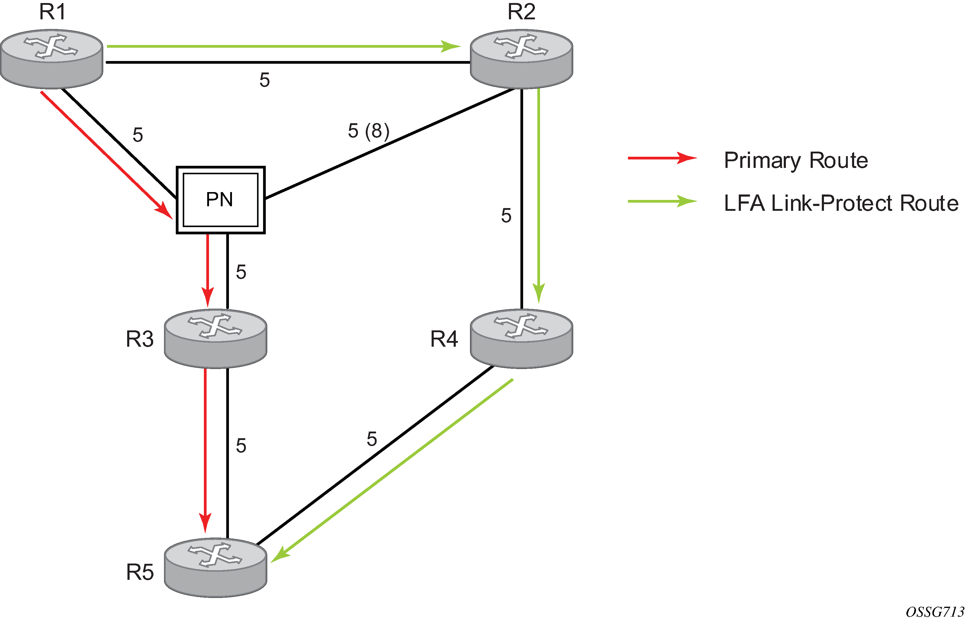
In order for next-hop R2 to be a link-protect LFA for route R5 from R1, it must be loop-free with respect to the R1-R3 link Pseudo-Node (PN). However, because R2 also has a link to that PN, its cost to reach R5 by way of the PN or router R4 is the same. Therefore, R1 cannot guarantee that enabling the LFA next-hop R2 protects against a failure impacting link R1-PN, because this may cause the entire subnet represented by the PN to go down. If the metric of link R2-PN is changed to 8, R2 next-hop is an LFA providing link protection.
The following are the detailed equations for this criterion as described in RFC 5286, Basic Specification for IP Fast Reroute: Loop-Free Alternates:
Rule 1
Link-protect LFA backup next-hop (primary next hop R1-R3 is a P2P interface):
Distance_opt(R2, R5) < Distance_opt(R2, R1) + Distance_opt(R1, R5)
Distance_opt(R2, R5) >= Distance_opt(R2, R3) + Distance_opt(R3, R5)
Rule 2
Node-protect LFA backup next-hop (primary next-hop R1-R3 is a P2P interface):
Distance_opt(R2, R5) < Distance_opt(R2, R1) + Distance_opt(R1, R5)
Distance_opt(R2, R5) < Distance_opt(R2, R3) + Distance_opt(R3, R5)
Rule 3
Link-protect LFA backup next-hop (primary next-hop R1-R3 is a broadcast interface):
Distance_opt(R2, R5) < Distance_opt(R2, R1) + Distance_opt(R1, R5)
Distance_opt(R2, R5) < Distance_opt(R2, PN) + Distance_opt(PN, R5), where PN stands for the R1-R3 link PN.
For a P2P interface, if SPF finds multiple LFA next-hops for a specified primary next-hop, it uses the following selection algorithm.
SPF picks the node-protect type in favor of the link-protect type.
If there is more than one LFA next-hop within the selected type, SPF picks one based on the least cost.
If more than one LFA next-hop with the same cost results from step 2, SPF selects the first one. This is not a deterministic selection and varies following each SPF calculation.
For a broadcast interface, a node-protect LFA is not necessarily a link-protect LFA if the path to the LFA next-hop goes over the same PN as the primary next-hop. Similarly, a link-protect LFA may not guarantee link protection if it goes over the same PN as the primary next-hop. The selection algorithm when SPF finds multiple LFA next-hops for a specified primary next-hop is modified as follows.
The algorithm splits the LFA next-hops into two sets.
The first set consists of LFA next-hops that do not go over the PN used by the primary next-hop.
The second set consists of LFA next-hops that go over the PN used by the primary next-hop.
If there is more than one LFA next-hop in the first set, SPF picks the node-protect type in favor of the link-protect type.
If there is more than one LFA next-hop within the selected type, SPF picks one based on the least cost.
If more than one LFA next-hop with equal cost results from step 3, SPF selects the first one from the remaining set. This is not a deterministic selection and varies following each SPF calculation.
If no LFA next-hop results from step D, SPF reruns steps 2 through 4 using the second set.
This algorithm is more flexible than strictly applying the preceding Rule 3; that is, the link-protect rule in the presence of a PN and specified in RFC 5286. A node-protect LFA that does not avoid the PN, that is, does not guarantee link protection, can still be selected as a last resort. Similarly, a link-protect LFA that does not avoid the PN can still be selected as a last resort.
Both the computed primary next-hop and LFA next-hop for a specified prefix are programmed into RTM.
Loop-free alternate calculation in the presence of IGP shortcuts
To expand the coverage of the LFA backup protection in a network, RSVP LSP based IGP shortcuts can be placed selectively in parts of the network and be used as an LFA backup next hop.
When IGP shortcut is enabled in IS-IS or OSPF on a specified node, all RSVP LSP originating on this node and with a destination address matching the router-id of any other node in the network are included in the main SPF by default.
To limit the time it takes to compute the LFA SPF, the user must explicitly enable the use of an IGP shortcut as LFA backup next hop using one of a couple of new optional argument for the existing LSP level IGP shortcut command:
config>router>mpls>lsp>igp-shortcut [lfa-protect | lfa-only]
The lfa-protect option allows an LSP to be included in both the main SPF and the LFA SPFs. For a specified prefix, the LSP can be used either as a primary next hop or as an LFA next hop but not both. If the main SPF computation selected a tunneled primary next hop for a prefix, the LFA SPF does not select an LFA next hop for this prefix and the protection of this prefix relies on the RSVP LSP FRR protection. If the main SPF computation selected a direct primary next hop, the LFA SPF selects an LFA next hop for this prefix but prefers a direct LFA next hop over a tunneled LFA next hop.
The lfa-only option allows an LSP to be included in the LFA SPFs only such that the introduction of IGP shortcuts does not impact the main SPF decision. For a specified prefix, the main SPF always selects a direct primary next hop. The LFA SPF selects a an LFA next hop for this prefix but prefers a direct LFA next hop over a tunneled LFA next hop.
With the selection algorithm when SPF finds multiple LFA next hops for a specified primary next hop is modified as follows.
The algorithm splits the LFA next hops into two sets:
The first set consists of direct LFA next hops.
The second set consists of tunneled LFA next hops. After excluding the LSPs which use the same outgoing interface as the primary next hop.
The algorithms continues with first set if not empty, otherwise it continues with second set.
If the second set is used, the algorithm selects the tunneled LFA next hop which endpoint corresponds to the node advertising the prefix.
If more than one tunneled next hop exists, it selects the one with the lowest LSP metric.
If still more than one tunneled next hop exists, it selects the one with the lowest tunnel-id.
If none is available, it continues with rest of the tunneled LFAs in second set.
Within the selected set, the algorithm splits the LFA next hops into two sets:
The first set consists of LFA next hops which do not go over the PN used by primary next hop.
The second set consists of LFA next hops which go over the PN used by the primary next hop.
If there is more than one LFA next hop in the selected set, it picks the node-protect type in favor of the link-protect type.
If there is more than one LFA next hop within the selected type, it picks one based on the least total cost for the prefix. For a tunneled next hop, it means the LSP metric plus the cost of the LSP endpoint to the destination of the prefix.
If there is more than one LFA next hop within the selected type (ecmp-case) in the first set, it selects the first direct next hop from the remaining set. This is not a deterministic selection and varies following each SPF calculation.
If there is more than one LFA next hop within the selected type (ecmp-case) in the second set, it picks the tunneled next hop with the lowest cost from the endpoint of the LSP to the destination prefix. If there remains more than one, it picks the tunneled next hop with the lowest tunnel-id.
LFA calculation for inter-area and inter-level prefixes
When SPF resolves OSPF inter-area prefixes or IS-IS inter-level prefixes, it computes an LFA backup next hop to the same exit area or border router as used by the primary next hop.
Multi-homed prefix LFA extensions in OSPF
Feature configuration
The multi-homed prefix (MHP) LFA feature for IP FRR of OSPF routes and for SR-OSPF FRR is enabled using the following CLI command.
- classic
CLI
configure +--router +--ospf <0..31> +--loopfree-alternates +--multi-homed-prefix +--preference <all, none> - MD
CLI
configure
+--router
   +--ospf <0..31>
      +--loopfree-alternate
         +--multi-homed-prefix
            +--preference <all, none>
When applied to IP prefixes, IP FRR must also be enabled using the following command, which allows the programming of the backup paths in the FIB.
- classic
CLI
configure +--router +--ip-fast-reroute - MD
CLI
configure
+--routing-options
   +--ip-fast-reroute
This feature makes use of the multi-homed prefix model described in RFC 8518 to compute a backup IP next hop via an alternate ABR or ASBR for external prefixes and to an alternate router owner for local anycast prefixes.
The base LFA algorithm is applied to all intra-area and external IP prefixes (IP FRR) and SR-OSPF node SID tunnels (SR-OSPF FRR), as usual. Then the MHP LFA is applied to improve the protection coverage for external prefixes and anycast prefixes. For external /32 prefixes and intra-area local /32 prefixes with multiple owner routers (anycast prefixes), the base LFA backup path, if found, is preferred over the MHP LFA backup in the default behavior with the preference command set to a value of none. The user can force the programming of the MHP LFA backup by setting the preference command value to all. The algorithm details are described in RFC 8518 MHP LFA for OSPF.
After the IP next-hop based MHP LFA is enabled, the extensions to MHP LFA to compute an SR-TE repair tunnel for an SR-OSPF tunnel are automatically enabled when the following CLI command is configured to enable Topology-Independent Loop-Free Alternate (TI-LFA) or Remote Loop-Free Alternate (RLFA). The algorithm details are described in 7750 SR and 7950 XRS Segment Routing and PCE User Guide, section LFA solution across IGP area or instance boundary using SR repair tunnel for SR OSPF. The computation reuses the SID list of the primary path or the TI-LFA or RLFA backup path of the alternate ABR, ASBR, or alternate owner router.
- classic
CLI
configure +--router +--ospf <0..31> +--loopfree-alternates +--remote-lfa +--ti-lfa - MD
CLI
configure
+--router
   +--ospf <0..31>
      +--loopfree-alternate
         +--remote-lfa
         +--ti-lfa
TI-LFA, base LFA and RLFA (if enabled) are applied to the SR-OSPF tunnels of all intra-area and external /32 prefixes as usual. For node SID SR-OSPF tunnels of external /32 prefixes or intra-area /32 anycast prefixes, the LFA, TI LFA, or RFLA backup path is preferred over the MHP LFA backup path in the default behavior with the preference command set to a value of none. The user can force the programming of the MHP LFA backup by setting the preference command value to all.
The MHP backup path protects SR-OSPF tunnels in both algorithm 0 and flexible-algorithm numbers. It also extends the protection to any SR-TE LSP or SR policy that uses an SR-OSPF SID of those same prefixes in its configured or computed SID list.
Feature applicability
The multi-homed-prefix command enables the feature but its applicability depends on the LFA flavor enabled in the OSPF instance. The following scenarios are possible.
-
loopfree-alternate and multi-homed-prefix commands are enabled
The IP next-hop based MHP LFA feature enhances base LFA only; it applies to IP FRR (when ip-fast-reroute is also enabled) and to SR-OSPF tunnels.
-
loopfree-alternate remote-lfa, loopfree-alternate ti-lfa, or both and multi-homed-prefix commands are enabled
The enabling of RLFA, TI-LFA, or both on top of the MHP LFA automatically enables the SR OS specific extensions to the IP next-hop backup algorithm in RFC 8515. This enhancement improves coverage because it computes SR-TE backup repair tunnel to an alternate ASBR as a means to force the packet to go to the alternate ASBR because the RFC 8518 MHP LFA may not find a loop-free path to this alternate ASBR.
RFC 8518 MHP LFA for OSPF
This feature uses the multi-homed prefix model described in RFC 8518 to compute a backup IP next hop using an alternate ABR or ASBR for external prefixes and to an alternate router owner for local anycast prefixes.
Note that the scope of the algorithm defined in RFC 8518 is limited to computed backup paths that consist of direct IP next hops and tunneled next hops (IGP shortcuts).
The SR OS implementation also extends the algorithm in RFC 8518 with computing the backup path to an alternate inter-area ASBR. The computed backup paths are added to OSPF routes of external /32 prefixes (OSPFv2 route types 3, 4, 5, and 7) and intra-area /32 anycast prefixes in the RTM if the prefixes are not protected by the base LFA or if the user has set the preference command value to all. The user must enable the ip-fast-reroute command to program these backup paths into the FIB in the data path.
The computed backup path is also programmed for SR-OSPF node SID tunnels of external /32 prefixes and of local /32 anycast prefixes in both algorithm 0 and flexible-algorithm numbers. The backup path, therefore, also extends the protection to any SR-TE LSP or SR policy that uses an SR-OSPF SID of those same prefixes in its configured or computed SID list.
The following figure shows the application of an MHP LFA to IP FRR.
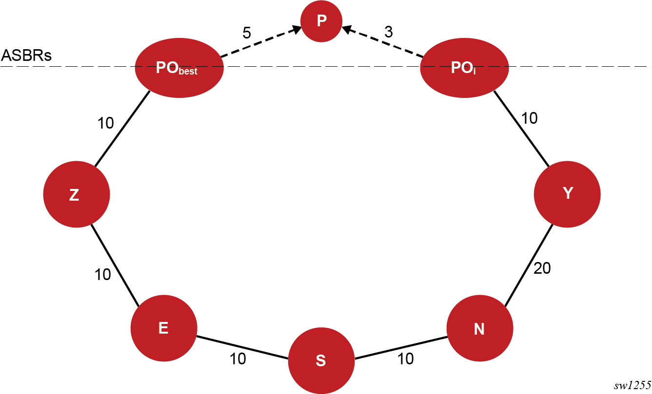
RFC 8518 creates a specific topology for each external prefix by modeling it as a multi-homed node to the Points of Attachment (POi nodes). POi can be an ASBR node for an external prefix or an owner router in the case of an intra-area anycast prefix. The SR OS implementation supports prefixes redistributed by an ABR or ASBR (OSPFv2 route types 3, 5, and 7) and also extends feature support to inter-area ASBR (external routes resolved recursively to OSPFv2 route types 4).
In the topology shown in Application of MHP LFA to IP FRR, prefix P has a dotted link with a metric of 5 to ABR or ASBR node PObest that summarizes the path in the remote OSPF area or instance to the best ABR or ASBR. Node PObest is ABR or ASBR that lies in the shortest path from the computing node S to the destination prefix P .
Prefix P also has a dotted line to ABR or ASBR POi that summarizes the path to an alternate ABR or ASBR with a cost of 3. Node POi propagates prefix P to the local area or instance of computing node S because its shortest path to P is in the remote area or instance, but POi does not lie in the shortest path to P from the point of view of node S.
Node S computes and finds a MHP LFA backup path for an external prefix P using neighbor N and which uses ABR or ASBR POi to exit the local area or instance, or which uses an alternate owner router for an intra-area anycast prefix, if the following rules are satisfied.
- Protection of Link S-E (1)
D_opt(N,POi) + Cost(POi ,P) < D_opt(N,S) + D_opt(S,PObest) + Cost(PObest ,P)
- Protection of Link E (2)
D_opt(N,POi) + Cost(POi ,P) < D_opt(N,E) + D_opt(E,PObest) + Cost(PObest ,P)
Where, D_opt(X,Y) is the distance on the shortest path from node X to node Y and Cost (X,P) is the external cost to reach prefix P from advertising router X.
The MHP LFA calculation applies to the backup next hop of external OSPFv2 /32 prefixes, propagated across an area or instance boundary, and resolved in RTM when IP FRR is enabled in that OSPFv2 instance. The calculation also applies to /32 prefixes in the same area as the computing node S that are advertised by multiple routers (anycast prefixes).
OSPFv2 runs concurrently the base LFA and the MHP LFA computations.
When the alternate ASBR or ABR node POi receives the packet, it always forwards it to the adjacent area but the path to prefix P in that area may use node PObest. When PObest fails, node S has a non-working backup path, which blackholes packets if activated during that same time until IGP converges. That is, unless the neighbor node of PObest in the adjacent area installed a node protect LFA path to reach P.
However, if node Z computed a multi-homed backup path for prefix P using an alternate ABR or ASBR POi and that path traverses PObest in the adjacent area, a failure of PObest immediately causes a traffic blackhole. This is because node Z has information that the backup path it activated failed after IGP converged in the adjacent area and POi updated the local area.
Enhancement to RFC 8518 Algorithm for backup path overlap with path to PObest in the local area
The RFC 8518 inequalities in the preceding section for computing a backup path using an alternate ASBR or ABR node POi can in some topologies result in a path that may still traverse the best ASBR or ABR node PObest in the local area.
The SR OS implementation enhances the node S computation of the backup path by applying the following additional inequality to detect that situation:
D_opt(N,POi)+ Cost(POi,P) < D_opt(N,PObest)+ Cost(PObest,P)
Node S prefers a path using a POi node which satisfies this inequality. If there is no such POi node, and in the case of an external prefix or an anycast SID prefix of a SR-OSPF tunnel, node S attempts to compute a SR repair tunnel following the enhancement to this feature described in 7750 SR and 7950 XRS Segment Routing and PCE User Guide, section LFA solution across IGP area or instance boundary using SR repair tunnel for SR OSPF.
An example topology in which an SR repair tunnel is preferred over the overlapping IP next-hop based backup path is provided in 7750 SR and 7950 XRS Segment Routing and PCE User Guide, section Example application of MH prefix LFA with repair tunnel.
In all cases, the backup path using the POi node which does not satisfy this inequality is programmed as a last resort.
Interaction with LFA policy
When a LFA policy is enabled on an interface, it applies to the backup path computation of all prefixes, intra-area and external, and to each base LFA, TI-LFA, RLFA and the MHP LFA path computations.
Application of LFA policy to MHP calculation shows the application of LFA policy in the calculation of a MHP LFA backup path. In this example, the topology shows inter-area ASBR nodes that are advertising external prefix P.
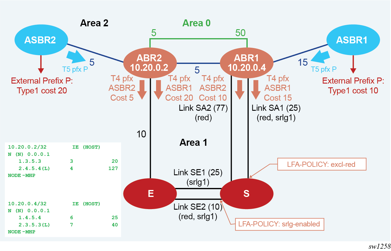
Each ASBR advertises within Area 2 a route type 5 with the cost to reach prefix P, which is propagated by ABR1 and ABR2 into Area 1. This also triggers ABR1 and ABR2 to advertise into Area 1 a route type 4 for each of the prefixes of ASBR1 and ASBR2.
Node S resolves prefix P by recursively with the best path of cost 45 using ABR2 or ASBR2 and link SE2. Base LFA finds a link-protect backup path of cost 60 using ABR2 or ASBR2 and link SE1.
When an LFA policy is applied to link SE2 to exclude its SRLG in the backup path computation, the backup path using link SE2 is excluded. Furthermore, ABR1 and ABR2 do not have a link in local Area 1 and, therefore, no path exists using ABR1 to ABR2 exit router in Area 1. As a result, prefix P remains without protection.
Next, the MHP LFA in node S is enabled. Now S can use the backup path of cost 102 using alternate exit ABR1 to reach ASBR1 and link SA2. This MHP LFA backup path satisfies the SRLG constraint.
Loop-free alternate shortest path first policies
A Loop-Free Alternate Shortest Path First (LFA SPF) policy allows the user to apply specific criteria, such as admin group and SRLG constraints, to the selection of a LFA backup next hop for a subset of prefixes that resolve to a specific primary next hop. The feature introduces the concept of route next hop template to influence LFA backup next hop selection.
Configuring a route next hop policy template
The LFA SPF policy consists of applying a route next hop policy template to a set of prefixes.
The user first creates a route next hop policy template under the global router context.
CLI syntax
config>router>route-next-hop-policy>template template-nameA policy template can be used in both IS-IS and OSPF to apply the specific criteria described in the next sub-sections to prefixes protected by LFA. Each instance of IS-IS or OSPF can apply the same policy template to one or more prefix lists and to one or more interfaces.
The commands within the route next hop policy use the begin-commit-abort model introduced with BFD templates. The following are the steps to create and modify the template.
To create a template, the user enters the name of the new template directly under route-next-hop-policy context.
To delete a template which is not in use, the user enters the no form for the template name under the route-next-hop-policy context.
The user enters the editing mode by executing the begin command under route-next-hop-policy context. The user can then edit and change any number of route next hop policy templates. However, the parameter value can still be stored temporarily in the template module until the commit is executed under the route-next-hop-policy context. Any temporary parameter changes are lost if the user enters the abort command before the commit command.
The user is allowed to create or delete a template instantly when in the editing mode without the need to enter the commit command. Furthermore, the abort command if entered has no effect on the prior deletion or creation of a template.
After the commit command is issued, IS-IS or OSPF re-evaluates the templates and if there are any net changes, it schedules a new LFA SPF to re-compute the LFA next hop for the prefixes associated with these templates.
Configuring affinity or admin group constraints
Administrative groups (admin groups), also known as affinity, are used to tag IP interfaces which share a specific characteristic with the same identifier. For example, an admin group identifier could represent all links which connect to core routers, or all links which have bandwidth higher than 10G, or all links which are dedicated to a specific service.
The user first configures locally on each router the name and identifier of each admin group.
CLI syntax
config>router>if>if-attribute>admin-group group-name value group-valueA maximum of 32 admin groups can be configured per system.
Next the user configures the admin group membership of the IP interfaces used in LFA. The user can apply admin groups to IES, VPRN, or network IP interface.
CLI syntax
config>router>interface>if-attribute>admin-group group-name [group-name...(up to 5 max)]
config>service>ies>if>if-attribute>admin-group group-name [group-name...(up to 5 max)]
config>service>vprn >if>if-attribute>admin-group group-name [group-name...(up to 5 max)]
The user can add as many admin groups as configured to a specified IP interface. The same above command can be applied multiple times.
The no form of the admin-group command under the interface deletes one or more of the admin-group memberships of the interface. It deletes all memberships if no group name is specified.
Finally, the user adds the admin group constraint into the route next hop policy template.
CLI syntax
configure router route-next-hop-template template template-name
include-group group-name [pref 1]
include-group group-name [pref 2]
exclude-group group-name
Each group is entered individually. The include-group statement instructs the LFA SPF selection algorithm to pick up a subset of LFA next hops among the links which belong to one or more of the specified admin groups. A link which does not belong to at least one of the admin-groups is excluded. However, a link can still be selected if it belongs to one of the groups in a include-group statement but also belongs to other groups which are not part of any include-group statement in the route next hop policy.
The pref option is used to provide a relative preference for the admin group to select. A lower preference value means that LFA SPF first attempts to select a LFA backup next hop which is a member of the corresponding admin group. If none is found, then the admin group with the next higher preference value is evaluated. If no preference is configured for a specified admin group name, then it is supposed to be the least preferred (for example, numerically the highest preference value).
When evaluating multiple include-group statements within the same preference, any link which belongs to one or more of the included admin groups can be selected as an LFA next hop. There is no relative preference based on how many of those included admin groups the link is a member of.
The exclude-group statement simply prunes all links belonging to the specified admin group before making the LFA backup next hop selection for a prefix.
If the same group name is part of both include and exclude statements, the exclude statement wins. It other words, the exclude statement can be viewed as having an implicit preference value of 0.
Configuring SRLG group constraints
Shared Risk Loss Group (SRLG) is used to tag IP interfaces which share a specific fate with the same identifier. For example, an SRLG group identifier could represent all links which use separate fibers but are carried in the same fiber conduit. If the conduit is accidentally cut, all the fiber links are cut which means all IP interfaces using these fiber links fail. The user can enable the SRLG constraint to select a LFA next hop for a prefix which avoids all interfaces that share fate with the primary next.
The user first configures locally on each router the name and identifier of each SRLG group.
CLI syntax
config>router>if-attribute>srlg-group group-name value group-valueA maximum of 1024 SRLGs can be configured per system.
Next the user configures the admin group membership of the IP interfaces used in LFA. The user can apply SRLG groups to IES, VPRN, or network IP interface.
CLI syntax
config>router>if>if-attribute>srlg-group group-name [group-name...(up to 5 max)]
config>service>vprn>if>if-attribute>srlg-group groupname [group-name...(up to 5 max)]
config>service>ies>if>if-attribute>srlg-group groupname [group-name...(up to 5 max)]
The user can add a maximum of 64 SRLG groups to a specified IP interface. The same above command can be applied multiple times.
The no form of the srlg-group command under the interface deletes one or more of the SRLG memberships of the interface. It deletes all SRLG memberships if no group name is specified.
Finally, the user adds the SRLG constraint into the route next hop policy template.
CLI syntax
configure router route-next-hop-template template
 template-name
srlg-enable
When this command is applied to a prefix, the LFA SPF selects a LFA next hop, among the computed ones, which uses an outgoing interface that does not participate in any of the SRLGs of the outgoing interface used by the primary next hop.
Interaction of IP and MPLS admin group and SRLG
The LFA SPF policy feature generalizes the use of admin-group and SRLG to other types of interfaces. To that end, it is important that the IP admin groups and SRLGs be compatible with the ones already supported in MPLS. The following rules are implemented.
The binding of an MPLS interface to a group, that is, configuring membership of an MPLS interface in a group, is performed under config>router>mpls>interface context.
The binding of a local or remote MPLS interface to an SRLG in the SRLG database is performed under the config>router>mpls>srlg-database context.
The binding of an IS-IS/OSPF interface to a group is performed in the config>router>if>if-attribute or config>service>vprn>if>if-attribute or config>service>ies>if>if-attribute contexts. This is used by IS-IS or OSPF in route next hop policies.
Only the admin groups and SRLGs bound to an MPLS interface context or the SRLG database context are advertised in TE link TLVs and sub-TLVs when the traffic-engineering option is enabled in IS-IS or OSPF. IES and VPRN interfaces do not have their attributes advertised in TE TLVs.
Configuring protection type and next hop type preferences
The user can select if link protection or node protection is preferred in the selection of a LFA next hop for all IP prefixes and LDP FEC prefixes to which a route next hop policy template is applied. The default in SR OS implementation is node protection. The implementation falls back to the other type if no LFA next hop of the preferred type is found.
The user can also select if tunnel backup next hop or IP backup next hop is preferred. The default in SR OS implementation is to prefer IP next hop over tunnel next hop. The implementation falls back to the other type if no LFA next hop of the preferred type is found.
The following options are added into the Route next hop policy template.
CLI syntax
configure router route-nh-template template template-name
   protection-type {link | node}
   nh-type {ip | tunnel}
When the route next hop policy template is applied to an IP interface, all prefixes using this interface as a primary next hop follows the protection type and next hop type preference specified in the template.
Application of route next hop policy template to an interface
After the route next hop policy template is configured with the needed policies, the user can apply it to all prefixes whose primary next hop uses a specific interface name. The following command achieves that.
CLI syntax:
config>router>isis>if>lfa-policy-map route-nh-template template-name
config>router>ospf(3)>area>if>lfa-policy-map route-nh-template template-name
config>service>vprn>ospf(3)>area>if>lfa-policy-map route-nh-template template-name
When a route next hop policy template is applied to an interface in IS-IS, it is applied in both level 1 and level 2. When a route next hop policy template is applied to an interface in OSPF, it is applied in all areas. However, the above CLI command in an OSPF interface context can only be executed under the area in which the specified interface is primary and then applied in that area and in all other areas where the interface is secondary. If the user attempts to apply it to an area where the interface is secondary, the command fails.
If the user excluded the interface from LFA using the command loopfree-alternate-exclude, the LFA policy if applied to the interface has no effect.
Finally, if the user applied a route next hop policy template to a loopback interface or to the system interface, the command is not rejected but it results in no action taken.
Excluding prefixes from LFA SPF
In the current SR OS implementation, the user can exclude an interface in IS-IS or OSPF, an OSPF area, or an IS-IS level from the LFA SPF.
This feature adds the ability to exclude prefixes from a prefix policy which matches on prefixes or on IS-IS tags.
CLI syntax
config>router>isis>loopfree-alternates exclude
prefix-policy prefix-policy1 [prefix-policy2…up to 5]
config>router>ospf(3)>loopfree-alternates exclude
prefix-policy prefix-policy1 [prefix-policy2…up to 5]
config>service>vprn>ospf(3)>loopfree-alternates exclude
prefix-policy prefix-policy1 [prefix-policy2…up to 5]
The prefix policy is configured as in existing SR OS implementation.
CLI syntax
config
  router
    policy-options
      [no] prefix-list prefix-list1
        prefix 62.225.16.0/24 prefix-length-range 32-
         32
      [no] policy-statements prefix-policy1
        entry 10
        from
          prefix-list "prefix-list1"
        exit
          action accept
        exit
        exit
          default-action reject
exit
If the user enabled the IS-IS prefix prioritization based on tag, it also applies to SPF LFA. If a prefix is excluded from LFA, it is not included in LFA calculation regardless of its priority. However, the prefix tag can be used in the main SPF.
The default action of the loopfree-alternates exclude command when not explicitly specified by the user in the prefix policy is a ‟reject”. Consequently, regardless of whether the user did or did not explicitly add the statement ‟default-action reject” to the prefix policy, a prefix that did not match any entry in the policy is accepted into LFA SPF.
Modification to LFA next hop selection algorithm
This feature modifies the LFA next-hop selection algorithm. The SRLG and admin-group criteria are applied before running the LFA next-hop selection algorithm. In other words, links which do not include one or more of the admin-groups in the include-group statements and links which belong to admin-groups which have been explicitly excluded using the exclude-group statement, and the links which belong to the SRLGs used by the primary next hop of a prefix are first pruned.
This pruning applies only to IP next hops. Tunnel next hops can have the admin-group or SRLG constraint applied to them under MPLS. For example, if a tunnel next hop is using an outgoing interface which belongs to a specific SRLG ID, the user can enable the srlg-frr option under the config>router>mpls context to be sure the RSVP LSP FRR backup LSP does not use an outgoing interface with the same SRLG ID. A prefix which is resolved to a tunnel next hop is protected by the RSVP FRR mechanism and not by the IP FRR mechanism. Similarly, the user can include or exclude admin-groups for the RSVP LSP and its FRR bypass backup LSP in MPLS context. The admin-group constraints can, however, be applied to the selection of the outgoing interface of both the LSP primary path and its FRR bypass backup path.
The following is the modified LFA selection algorithm which is applied to prefixes resolving to a primary next hop which uses a specific route next hop policy template.
Split the LFA next hops into two sets:
IP or direct next hops.
Tunnel next hops after excluding the LSPs which use the same outgoing interface as the primary next hop.
Prune the IP LFA next hops which use the following links:
Links which do not include one or more of the admin-groups in the include-group statements in the route next hop policy template.
Links which belong to admin-groups which have been explicitly excluded using the exclude-group statement in the route next hop policy template.
Links which belong to the SRLGs used by the primary next hop of a prefix.
Continue with the set indicated in the nh-type value in the route next hop policy template if not empty; otherwise continue with the other set.
Within IP next hop set:
Prefer LFA next hops which do not go over the Pseudo-Node (PN) used by the primary next hop.
Within selected subset prefer the node-protect type or the link-protect type according to the value of the protection-type option in the route next hop policy template.
Within the selected subset, select the best admin-groups according to the preference specified in the value of the include-group option in the route next hop policy template.
Within selected subset, select lowest total cost of a prefix.
If same total cost, select lowest router-id.
If same router-id, select lowest interface-index.
Within tunnel next hop set:
Select tunnel next hops which endpoint corresponds to the node owning or advertising the prefix.
Within selected subset, select the one with the lowest cost (lowest LSP metric).
If same lowest cost, select tunnel with lowest tunnel-index.
If none is available, continue with rest of the tunnel LFA next hop set.
Prefer LFA next hops which do not go over the Pseudo-Node (PN) used by the primary next hop.
Within selected subset prefer the node-protect type or the link-protect type according to the value of the protection-type in the route next hop policy template.
Within selected subset, select lowest total cost of a prefix. For a tunnel next hop, it means the LSP metric plus the cost of the LSP endpoint to the destination of the prefix.
If same total cost, select lowest endpoint to destination cost.
If same endpoint to destination cost, select lowest router-id.
If same router-id, select lowest tunnel-index.
SPF LSA filtering
The SR OS OSPF implementation supports a configuration option to filter outgoing OSPF LSAs on selected OSPFv2 or OSPFv3 interfaces. This feature should be used with some caution because it goes against the principle that all OSPF routers in an area should have a synchronized Link State Database (LSDB), but it can be a useful resource saving in specific hub and spoke topologies where learning routes through OSPF is only needed in one direction (for example, from spoke to hub).
Three filtering options are available (configurable per interface).
Do not flood any LSAs out the interface. This option is suitable if the neighbor is simply-connected and has a statically configured default route with the address of this interface as next hop.
Flood a minimum set of self-generated LSAs out the interface (for example, router-LSA, intra-area-prefix-LSA, and link-LSA and network-LSA corresponding to the connected interface); suppress all non-self-originated LSAs. This option is suitable if the neighbor is simply connected and has a statically configured default route with a loopback or system interface address as next hop.
Flood a minimum set of self-generated LSAs (for example, router-LSA, intra-area-prefix-LSA, and link-LSA and network-LSA corresponding to the connected interface) and all self-generated type-3, type-5 and type-7 LSAs advertising a default route (0/0) out the interface; suppress all other flooded LSAs. This option is suitable if the neighbor is simply-connected and does not have a statically configured default route.
FIB prioritization
The RIB processing of specific routes can be prioritized through the use of the rib-priority command. This command allows specific routes to be prioritized through the protocol processing so that updates are propagated to the FIB as quickly as possible.
Configuring the rib-priority command either within the global OSPF or OSPFv3 routing context or under a specific OSPF/OSPFv3 interface context enables this feature. Under the global OSPF context, a prefix list can be specified that identifies which route prefixes should be considered high priority. If the rib-priority high command is configured under an OSPF interface context, all routes learned through that interface is considered high priority.
The routes that have been designated as high priority are the first routes processed and then passed to the FIB update process so that the forwarding engine can be updated. All known high priority routes should be processed before the OSPF routing protocol moves on to other standard priority routes. This feature has the most impact when a large number of routes are learned through the OSPF routing protocols.
Extended LSA support in OSPFv3
This feature adds support for the extended LSA format in OSPFv3 as described in draft-ietf-ospf-ospfv3-lsa-extend, OSPFv3 LSA Extendibility.
Before this feature, the SR OS used the fixed-format LSA to carry the prefix and link information as described in RFC 5340, OSPF for IPv6. The fixed-format is not extensible, for this reason it needs to use the TLV format of the extended LSA.
With this feature, the default mode of operation for OSPFv3 is referred to as sparse mode, meaning that the router advertises the fixed-format for existing LSAs and adds the TLV-based extended LSA only when it needs to advertise new sub-TLVs. This mode of operation is very similar to the way OSPFv2 advertises the Segment Routing information. It sends the prefix in the original fixed-format prefix LSA and then follows with the extended prefix TLV which is sent in an extended prefix opaque LSA containing the prefix SID sub-TLV.
The extended-lsa only value enables the full extended LSA mode and this causes all existing and new LSAs to use the extended LSA format.
An OSPFv3 area inherits the instance level configuration but can also be configured independently to the sparse of full extended LSA mode.
The OSPFv3 instance must first be shut down before the user can change the mode of operation, because the protocol must flush all LSAs and re-establish all adjacencies.
Support of multiple instances of router information LSA in OSPFv2 and OSPFv3
This feature adds the support of multiple instances of the Router Information LSA as described in RFC 7770, Extensions to OSPF for Advertising Optional Router Capabilities.
The original method of advertising router capabilities used options fields in LSAs and hello packets. However, this method is not extensible because of the limited size of the options field. The RFC 4970, Extensions to OSPF for Advertising Optional Router Capabilities, defined the Router Information LSA which can carry multiple router capability TLVs. It also defined a single TLV called the Router Informational Capabilities TLV to carry all previously defined capabilities in the options field in LSAs and hello packets. The SR OS supports RFC 4970.
RFC 7770 deprecated RFC 4970 by adding the ability to send multiple instances of the Router Information LSA to circumvent the maximum LSA size of 64 kbytes.
There is no CLI to enable the support of multiple instances of the Router Information LSA. The existing Router Information Capabilities TLVs is carried as the first TLV (Opaque ID 0) of the first instance (instance ID 0) of the Router Information LSA. The existing router information TLVs, such as the OSPFv2 SR-Algorithm TLV and the SID/Label Range TLV, are sent in the first instance of the Router Information LSA.
If a router information TLV is received in multiple instances of the Router Information LSA, the default behavior is to process the one in the lowest instance ID and ignore the other ones.
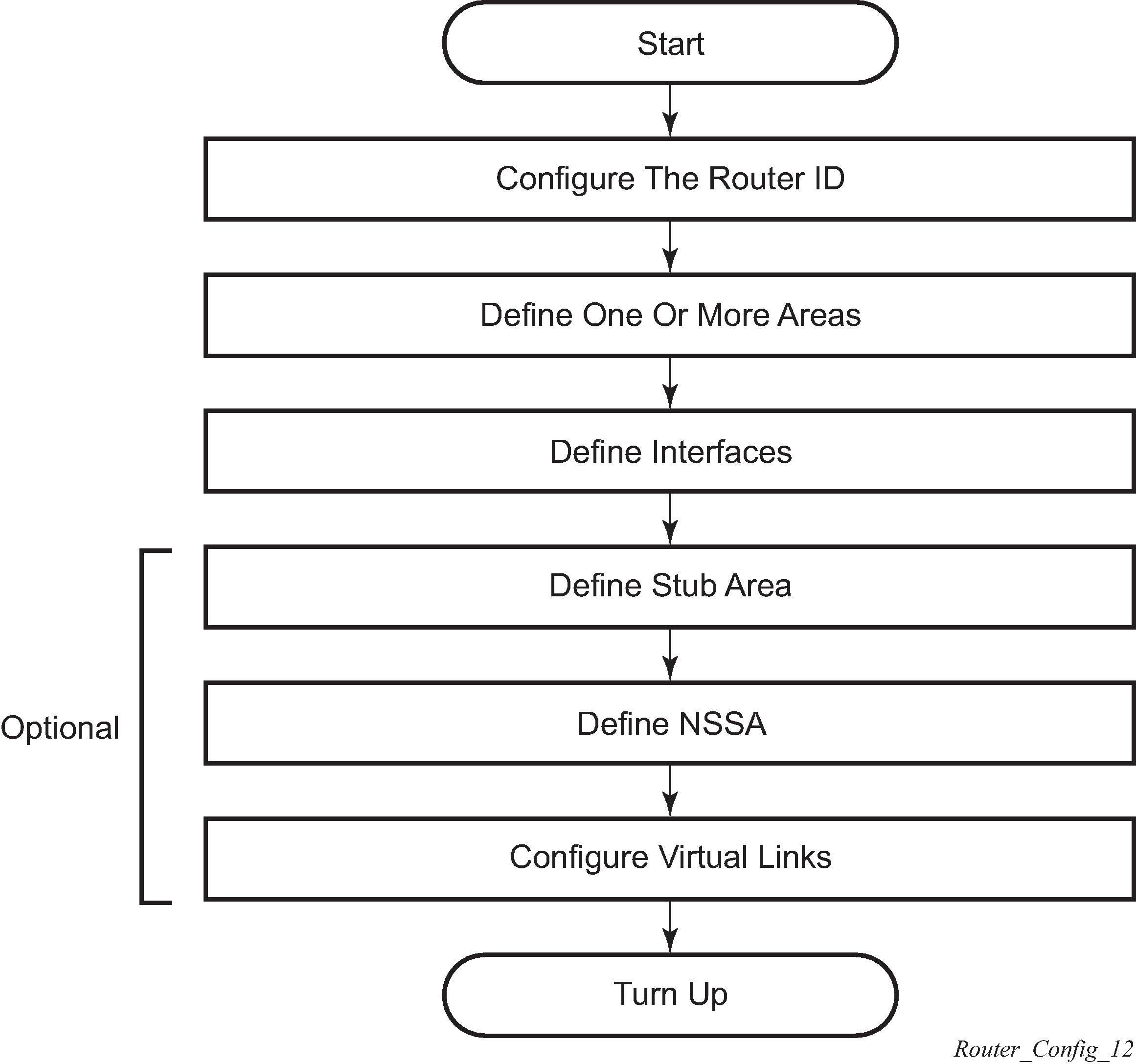
OSPF configuration process overview
OSPF configuration and implementation flow displays the process to provision basic OSPF parameters.
Configuration notes
This section describes OSPF configuration restrictions.
General
Before OSPF can be configured, the router ID must be configured.
The basic OSPF configuration includes at least one area and an associated interface.
All default and command parameters can be modified.
OSPF defaults
The following list summarizes the OSPF configuration defaults.
By default, a router has no configured areas.
An OSPF instance is created in the administratively enabled state.
Configuring OSPF with CLI
This section provides information to configure Open Shortest Path First (OSPF) using the command line interface.
OSPF configuration guidelines
Configuration planning is essential to organize routers, backbone, non-backbone, stub, NSSA areas, and transit links. OSPF provides essential defaults for basic protocol operability. You can configure or modify commands and parameters. OSPF is not enabled by default.
The minimal OSPF parameters which should be configured to deploy OSPF are described below.
Router ID
Each router running OSPF must be configured with a unique router ID. The router ID is used by both OSPF and BGP routing protocols in the routing table manager.
When configuring a new router ID, protocols are not automatically restarted with the new router ID. Shut down and restart the protocol to initialize the new router ID.
OSPF instance
OSPF instances must be defined when configuring multiple instances and the instance being configured is not the base instance.
An area
At least one OSPF area must be created. An interface must be assigned to each OSPF area.
Interfaces
An interface is the connection between a router and one of its attached networks. An interface has state information associated with it, which is obtained from the underlying lower level protocols and the routing protocol itself. An interface to a network has associated with it a single IP address and mask (unless the network is an unnumbered point-to-point network). An interface is sometimes also referred to as a link.
Basic OSPF configurations
This section provides information to configure OSPF and OSPF3 as well as configuration examples of common configuration tasks.
The minimal OSPF parameters that need to be configured are:
a router ID; if a router-id is not configured in the config>router context, the router’s system interface IP address is used
one or more areas
interfaces (interface "system")
The following is an example of a basic OSPF configuration:
ALA-A>config>router>ospf# info
----------------------------------------------
            area 0.0.0.0
                interface "system"
                exit
            exit
            area 0.0.0.20
                nssa
                exit
                interface "to-104"
                    priority 10
                exit
            exit
            area 0.0.1.1
            exit
----------------------------------------------
ALA-A>config>router>ospf#
The following is an example of a basic OPSF3 configuration:
A:ALA-48>config>router>ospf3# info
----------------------------------------------
            asbr
            overload
            timers
                lsa-arrival 50000
            exit
            export "OSPF-Export"
            area 0.0.0.0
                interface "system"
                exit
            exit
            area 0.0.0.20
                nssa
                exit
                interface "SR1-2"
                exit
            exit
            area 0.0.0.25
                stub
                    default-metric 5000
                exit
            exit
Configuring the router ID
The router ID uniquely identifies the router within an AS. In OSPF, routing information is exchanged between autonomous systems, groups of networks that share routing information. It can be set to be the same as the loopback (system interface) address. Subscriber services also use this address as far-end router identifiers when service distribution paths (SDPs) are created. The router ID is used by both OSPF and BGP routing protocols. A router ID can be derived by:
defining the value in the config>router router-id context
defining the system interface in the config>router>interface ip-int-name context (used if the router ID is not specified in the config>router router-id context)
inheriting the last four bytes of the MAC address
on the BGP protocol level, a BGP router ID can be defined in the config>router>bgp router-id context and is only used within BGP
defining a router ID when creating an OSPF instance config>router>ospf [instance-id] [router-id]
When configuring a new router ID, protocols are not automatically restarted with the new router ID. The next time a protocol is (re) initialized the new router ID is used. An interim period of time can occur when different protocols use different router IDs. To force the new router ID, issue the shutdown and no shutdown commands for each protocol that uses the router ID or restart the entire router.
It is possible to configure an SR OS to operate with an IPv6 only BOF and no IPv4 system interface address. When configured in this manner, the operator must explicitly define IPv4 router IDs for protocols such as OSPF and BGP as there is no mechanism to derive the router ID from an IPv6 system interface address.
The following displays a router ID configuration example:
A:ALA-B>config>router# info
#------------------------------------------
# IP Configuration
#------------------------------------------
        interface "system"
            address 10.10.10.104/32
        exit
        interface "to-103"
            address 10.0.0.104/24
            port 1/1/1
        exit
        autonomous-system 100
        router-id 10.10.10.104
...
#------------------------------------------
A:ALA-B>config>router#
Configuring OSPF components
Use the CLI syntax displayed in the following subsections to configure OSPF components.
Configuring OSPF parameters
The following displays a basic OSPF configuration example:
A:ALA-49>config>router>ospf# info
----------------------------------------------
            asbr
            overload
            overload-on-boot timeout 60
            traffic-engineering
            export "OSPF-Export"
            exit
----------------------------------------------
A:ALA-49>config>router>ospf# ex
Configuring OSPF3 parameters
Use the following CLI syntax to configure OSPF3 parameters.
CLI syntax
config>router# ospf3
  asbr
  export policy-name [policy-name...(up to 5 max)]
  external-db-overflow limit seconds
  external-preference preference
  overload [timeout seconds]
  overload-include-stub
  overload-on-boot [timeout seconds]
  preference preference
  reference-bandwidth bandwidth-in-kbps
  router-id ip-address
  no shutdown
  timers
    lsa-arrival lsa-arrival-time
    lsa-generate max-lsa-wait [lsa-initial-wait lsa-initial-wait [lsa-second-wait lsa-second-wait]]
    spf-wait max-spf-wait [spf-initial-wait spf-initial-wait [spf-second-wait spf-second-wait]]
The following displays an OSPF3 configuration example:
A:ALA-48>config>router>ospf3# info
----------------------------------------------
            asbr
            overload
            timers
                lsa-arrival 50000
            exit
            export "OSPF-Export"
----------------------------------------------
A:ALA-48>config>router>ospf3#
OSPF also supports the concept of multi-instance OSPFv2 and OSPFv3 which allows separate instances of the OSPF protocols to run independently within SR OSs.
Separate instances are created by adding a different instance ID as the optional parameter to the config>router>ospf and config>router>ospf3 commands. When this is done a separate OSPF instance is created which maintains separate link state databases for each instance.
Configuring an OSPF or OSPF3 area
An OSPF area consists of routers configured with the same area ID. To include a router in a specific area, the common area ID must be assigned and an interface identified.
If your network consists of multiple areas you must also configure a backbone area (0.0.0.0) on at least one router. The backbone consists of the area border routers and other routers not included in other areas. The backbone distributes routing information between areas. The backbone is considered to be a participating area within the autonomous system. To maintain backbone connectivity, there must be at least one interface in the backbone area or have a virtual link configured to another router in the backbone area.
The minimal configuration must include an area ID and an interface. Modifying other command parameters are optional.
Use the following CLI syntax to configure an OSPF area.
CLI syntax
ospf ospf-instance
area area-id
area-range ip-prefix/mask [advertise | not-advertise]
blackhole-aggregate
Use the following CLI syntax to configure an OSPF3 area.
CLI syntax
ospf ospf-instance
ospf3
area area-id
   area-range ip-prefix/mask [advertise | not-advertise]
   blackhole-aggregate
The following displays an OSPF area configuration example:
A:ALA-A>config>router>ospf# info
----------------------------------------------
            area 0.0.0.0
            exit
            area 0.0.0.20
            exit
----------------------------------------------
ALA-A>config>router>ospf#A:
Configuring a stub area
Configure stub areas to control external advertisements flooding and to minimize the size of the topological databases on an area's routers. A stub area cannot also be configured as an NSSA.
By default, summary route advertisements are sent into stub areas. The no form of the summary command disables sending summary route advertisements and only the default route is advertised by the ABR. This example retains the default so the command is not entered.
If this area is configured as a transit area for a virtual link, then existing virtual links of a non-stub or NSSA area are removed when its designation is changed to NSSA or stub.
Stub areas for OSPF3 are configured the same as OSPF stub areas.
Use the following CLI syntax to configure virtual links.
CLI syntax
ospf
  area area-id
  stub
  default-metric metric
  summaries
Use the following CLI syntax to configure virtual links for OSPF3.
CLI syntax
ospf
ospf3
  area area-id
  stub
  default-metric metric
  summaries
The following displays a stub configuration example:
ALA-A>config>router>ospf>area># info
----------------------------------------------
...
            area 0.0.0.0
            exit
            area 0.0.0.20
                stub
                exit
            exit
...
----------------------------------------------
ALA-A>config>router>ospf#
The following displays a stub configuration example for the OSPF3:
A:ALA-48>config>router>ospf3>area# info
----------------------------------------------
                stub
                    default-metric 5000
                exit
----------------------------------------------
A:ALA-48>config>router>ospf3>area#
Configuring a not-so-stubby area
You must explicitly configure an area to be a Not-So-Stubby Area (NSSA) area. NSSAs are similar to stub areas in that no external routes are imported into the area from other OSPF areas. The major difference between a stub area and an NSSA is an NSSA has the capability to flood external routes it learns throughout its area and by an area border router to the entire OSPF domain. An area cannot be both a stub area and an NSSA.
If this area is configured as a transit area for a virtual link, then existing virtual links of a non-stub or NSSA area are removed when its designation is changed to NSSA or stub.
Use the following CLI syntax to configure stub areas.
CLI syntax
ospf ospf-instance
    area area-id
  nssa
    area-range ip-prefix/mask [advertise|not-advertise]
    originate-default-route [type-7]
    redistribute-external
    summaries
Use the following CLI syntax to configure stub areas for the OSPF3.
CLI syntax
ospf ospf-instance
ospf3
    area area-id
  nssa
    area-range ip-prefix/mask [advertise|not-advertise]
    originate-default-route [type-7]
    redistribute-external
    summaries
The following displays an NSSA configuration example:
A:ALA-49>config>router>ospf# info
----------------------------------------------
            asbr
            overload
            overload-on-boot timeout 60
            traffic-engineering
            export "OSPF-Export"
            exit
            area 0.0.0.0
            exit
            area 0.0.0.20
                stub
                exit
            exit
            area 0.0.0.25
                nssa
                exit
            exit
----------------------------------------------
A:ALA-49>config>router>ospf#
The following displays a OSPF3 NSSA configuration example:
A:ALA-48>config>router>ospf3# info
----------------------------------------------
            asbr
            overload
            timers
                lsa-arrival 50000
            exit
            export "OSPF-Export"
            area 0.0.0.0
            exit
            area 0.0.0.20
                stub
                exit
            exit
            area 0.0.0.25
                nssa
                exit
            exit
            area 4.3.2.1
            exit
----------------------------------------------
A:ALA-48>config>router>ospf3#
Configuring a virtual link
The OSPF backbone area, area 0.0.0.0, must be contiguous and all other areas must be connected to the backbone area. The backbone distributes routing information between areas. If it is not practical to connect an area to the backbone (see Area 0.0.0.5 in OSPF areas) then the area border routers (such as routers Y and Z) must be connected via a virtual link. The two area border routers form a point-to-point-like adjacency across the transit area (see Area 0.0.0.4). A virtual link can only be configured while in the area 0.0.0.0 context.
The router-id parameter specified in the virtual-link command must be associated with the virtual neighbor, that is, enter the virtual neighbor’s router ID, not the local router ID. The transit area cannot be a stub area or an NSSA.
Use the following CLI syntax to configure stub areas.
CLI syntax
ospf ospf-instance
    area area-id
  virtual-link router-id transit-area area-id
    authentication-key [authentication-key|hash-key] [hash]
    authentication-type [password|message-digest]
    dead-interval seconds
    hello-interval seconds
    message-digest-key key-id md5 [key|hash-key] [hash|hash2|custom]
    retransmit-interval seconds
    transit-delay
    no shutdown
The following displays a virtual link configuration example:
A:ALA-49>config>router>ospf# info
----------------------------------------------
            asbr
            overload
            overload-on-boot timeout 60
            traffic-engineering
            export "OSPF-Export"
            exit
            area 0.0.0.0
                virtual-link 1.2.3.4 transit-area 1.2.3.4
                    hello-interval 9
                    dead-interval 40
                exit
            exit
            area 0.0.0.20
                stub
                exit
            exit
            area 0.0.0.25
                nssa
                exit
            exit
            area 1.2.3.4
            exit
----------------------------------------------
A:ALA-49>config>router>ospf#
The following displays an OSPF3 virtual link configuration example:
A:ALA-48>config>router>ospf3# info
----------------------------------------------
            asbr
            overload
            timers
                lsa-arrival 50000
            exit
            export "OSPF-Export"
            area 0.0.0.0
                virtual-link 4.3.2.1 transit-area 4.3.2.1
                exit
            exit
            area 0.0.0.20
                stub
                exit
            exit
            area 0.0.0.25
                nssa
                exit
            exit
            area 4.3.2.1
            exit
----------------------------------------------
A:ALA-48>config>router>ospf3#
Configuring an interface
In OSPF, an interface can be configured to act as a connection between a router and one of its attached networks. An interface includes state information obtained from underlying lower level protocols and from the routing protocol itself. An interface to a network is associated with a single IP address and mask (unless the network is an unnumbered point-to-point network). If the address is merely changed, the OSPF configuration is preserved.
By default, only interfaces that are configured under the OSPF interface context are advertised as OSPF interfaces. The passive command allows an interface to be advertised as an OSPF interface without running the OSPF protocol. When enabled, the interface ignores ingress OSPF protocol packets and does not transmit any OSPF protocol packets.
An interface can be part of more than one area, as specified in RFC 5185. This allows multiple secondary adjacencies, in addition to the primary adjacency, to be established over a single IP interface. To do this, add the keyword secondary when creating the interface. The keyword secondary can also be applied to the system interface and to loopback interfaces to allow them to participate in multiple areas, although no adjacencies are formed over these types of interfaces.
Use the following CLI syntax to configure an OSPF interface.
CLI syntax
ospf ospf-instance
  area area-id
    interface ip-int-name [secondary]
       advertise-subnet
       authentication-key [authenticationkey|hash-key] [hash|hash2|custom]
       authentication-type [password|messagedigest]
       bfd-enable [remain-down-on-failure]
       dead-interval seconds
       hello-interval seconds
       interface-type {broadcast|point-to-point|non-broadcast}
       message-digest-key key-id md5 [key|hashkey][hash|hash2|custom]
       metric metric
       mtu bytes
       passive
       priority number
       retransmit-interval seconds
       no shutdown
       transit-delay seconds
The following displays an interface configuration example:
A:ALA-49>config>router>ospf# info
----------------------------------------------
            asbr
            overload
            overload-on-boot timeout 60
            traffic-engineering
            export "OSPF-Export"
            exit
            area 0.0.0.0
                virtual-link 1.2.3.4 transit-area 1.2.3.4
                    hello-interval 9
                    dead-interval 40
                exit
                interface "system"
                exit
            exit
            area 0.0.0.20
                stub
                exit
                interface "to-103"
                exit
            exit
            area 0.0.0.25
                nssa
                exit
            exit
            area 1.2.3.4
            exit
 area 4.3.2.1
                interface "SR1-3"
                exit
            exit
            area 4.3.2.1
                interface "SR1-3" secondary
                exit
            exit
----------------------------------------------
A:ALA-49>config>router>ospf# area 0.0.0.20
The following displays an interface configuration:
A:ALA-48>config>router>ospf3# info
----------------------------------------------
            asbr
            overload
            timers
                lsa-arrival 50000
            exit
            export "OSPF-Export"
            area 0.0.0.0
                virtual-link 4.3.2.1 transit-area 4.3.2.1
                exit
                interface "system"
                exit
            exit
            area 0.0.0.20
                stub
                exit
                interface "SR1-2"
                exit
            exit
            area 0.0.0.25
                nssa
                exit
            exit
            area 4.3.2.1
            exit

----------------------------------------------
A:ALA-48>config>router>ospf3#
Configuring authentication
Overview
The use of protocol authentication is recommended to protect against malicious attack on the communications between routing protocol neighbors. These attacks could aim to either disrupt communications or to inject incorrect routing information into the systems routing table. The use of authentication keys can help to protect the routing protocols from these types of attacks.
Authentication must be explicitly configured and can be done so through two separate mechanisms. First is configuration of an explicit authentication key and algorithm through the use of the authentication and authentication-type commands. The second method is through the use of the authentication keychain mechanism. Both mechanisms are described in the following sections.
Configuring authentication keys and algorithms
The following authentication commands can be configured on the interface level or the virtual link level:
authentication-key
Configures the password used by the OSPF interface or virtual-link to send and receive OSPF protocol packets on the interface when simple password authentication is configured.
authentication-type
Enables authentication and specifies the type of authentication to be used on the OSPF interface, either password or message digest.
message-digest-key
Use this command when message-digest keyword is selected in the authentication-type command. The Message Digest 5 (MD5) hashing algorithm is used for authentication. MD5 is used to verify data integrity by creating a 128-bit message digest from the data input. It is unique to that specific data.
An special checksum is included in transmitted packets and are used by the far-end router to verify the packet by using an authentication key (a password). Routers on both ends must use the same MD5 key.
MD5 can be configured on each interface and each virtual link. If MD5 is enabled on an interface, then that interface accepts routing updates only if the MD5 authentication is accepted. Updates that are not authenticated are rejected. A router accepts only OSPF packets sent with the same key-id value defined for the interface.
When the hash parameter is not used, non-encrypted characters can be entered. After configured using the message-digest-key command, then all keys specified in the command are stored in encrypted format in the configuration file using the hash keyword. When using the hash keyword, the password must be entered in encrypted form. Hashing cannot be reversed. Issue the no message-digest-key key-id command, then re-enter the command without the hash parameter to configure an unhashed key.
The following CLI commands are displayed to illustrate the key authentication features. These command parameters can be defined at the same time interfaces and virtual-links are being configured. See Configuring an interface and Configuring a virtual link.
Use the following CLI syntax to configure authentication.
CLI syntax
ospf ospf-instance
    area area-id
  interface ip-int-name
    authentication-key [authentication-key|hash-key] [hash]
    authentication-type [password|message-digest]
    message-digest-key key-id md5 key [hash]
  virtual-link router-id transit-area area-id
    authentication-key [authentication-key|hash-key] [hash]
    authentication-type [password|message-digest]
    message-digest-key key-id md5 key [hash]
The following displays authentication configuration examples:
A:ALA-49>config>router>ospf# info
----------------------------------------------
            asbr
            overload
            overload-on-boot timeout 60
            traffic-engineering
            export "OSPF-Export"
            exit
            area 0.0.0.0
                virtual-link 1.2.3.4 transit-area 1.2.3.4
                    hello-interval 9
                    dead-interval 40
                exit
                interface "system"
                exit
            exit
            area 0.0.0.20
                stub
                exit
                interface "to-103"
                exit
            exit
            area 0.0.0.25
                nssa
                exit
            exit
            area 0.0.0.40
                interface "test1"
                    authentication-type password
                    authentication-key "3WErEDozxyQ" hash
                exit
            exit
            area 1.2.3.4
            exit
----------------------------------------------
A:ALA-49>config>router>ospf#

A:ALA-49>config>router>ospf# info
----------------------------------------------
            asbr
            overload
            overload-on-boot timeout 60
            traffic-engineering
            export "OSPF-Export"
            exit
            area 0.0.0.0
                virtual-link 10.0.0.1 transit-area 0.0.0.1
                    authentication-type message-digest
                    message-digest-key 2 md5 "Mi6BQAFi3MI" hash
                exit
                virtual-link 1.2.3.4 transit-area 1.2.3.4
                    hello-interval 9
                    dead-interval 40
                exit
                interface "system"
                exit
            exit
            area 0.0.0.1
            exit
            area 0.0.0.20
                stub
                exit
                interface "to-103"
                exit
            exit
            area 0.0.0.25
                nssa
                exit
            exit
            area 0.0.0.40
                interface "test1"
                    authentication-type password
                    authentication-key "3WErEDozxyQ" hash
                exit
            exit
            area 1.2.3.4
            exit
----------------------------------------------
A:ALA-49>config>router>ospf#
Configuring authentication using keychains
The use of authentication mechanism is recommended to protect against malicious attack on the communications between routing protocol neighbors. These attacks could aim to either disrupt communications or to inject incorrect routing information into the systems routing table. The use of authentication keys can help to protect the routing protocols from these types of attacks. In addition, the use of authentication keychains provides the ability to configure authentication keys and make changes to them without affecting the state of the routing protocol adjacencies.
To configure the use of an authentication keychain within OSPF, use the following steps.
Configure an authentication keychain within the config>system>security context. The configured keychain must include at least on valid key entry, using a valid authentication algorithm for the OSPF protocol.
Associate the configure authentication keychain within OSPF. Authentication keychains can be used to specify the authentication key and algorithm on a per interface basis within the configuration for the OSPF protocol.
For a key entry to be valid, it must include a valid key, the current system clock value must be within the begin and end time of the key entry, and the algorithm specified in the key entry must be supported by the OSPF protocol.
The OSPF protocol supports the following algorithms:
clear text password
MD5
HMAC-SHA-1-96
HMAC-SHA-1
HMAC-SHA-256
The keychain error handling is described below.
If a keychain exists but there are no active key entries with an authentication type that is valid for the associated protocol, then inbound protocol packets are not authenticated and discarded and no outbound protocol packets are sent.
If keychain exists, but the last key entry has expired, a log entry is raised indicating that all keychain entries have expired. The OSPF protocol requires that the protocol continue to authenticate inbound and outbound traffic using the last valid authentication key.
Assigning a designated router
A designated router is elected according to the priority number advertised by the routers. When a router starts up, it checks for a current designated router. If a designated router is present, then the router accepts that designated router, regardless of its own priority designation. When a router fails, then new designated and backup routers are elected according their priority numbers.
The priority command is only used if the interface is a broadcast type. The designated router is responsible for flooding network link advertisements on a broadcast network to describe the routers attached to the network. A router uses hello packets to advertise its priority. The router with the highest priority interface becomes the designated router. A router with priority 0 is not eligible to be a designated router or a backup designated router. At least one router on each logical IP network or subnet must be eligible to be the designated router. By default, routers have a priority value of 1.
Use the following CLI syntax to configure the designated router.
CLI syntax
ospf ospf-instance
   area area-id
 interface ip-int-name
   priority number
The following displays a priority designation example:
A:ALA-49>config>router>ospf# info
----------------------------------------------
            asbr
            overload
            overload-on-boot timeout 60
            traffic-engineering
            export "OSPF-Export"
            exit
            area 0.0.0.0
                virtual-link 10.0.0.1 transit-area 0.0.0.1
                    authentication-type message-digest
                    message-digest-key 2 md5 "Mi6BQAFi3MI" hash
                exit
                virtual-link 1.2.3.4 transit-area 1.2.3.4
                    hello-interval 9
                    dead-interval 40
                exit
                interface "system"
                exit
            exit
            area 0.0.0.1
            exit
            area 0.0.0.20
                stub
                exit
                interface "to-103"
                exit
            exit
            area 0.0.0.25
                nssa
                exit
                interface "if2"
                    priority 100
                exit
            exit
            area 0.0.0.40
                interface "test1"
                    authentication-type password
                    authentication-key "3WErEDozxyQ" hash
                exit
            exit
            area 1.2.3.4
            exit
----------------------------------------------
A:ALA-49>config>router>ospf#
Configuring route summaries
Area border routers send summary (type 3) advertisements into a stub area or NSSA to describe the routes to other areas. This command is particularly useful to reduce the size of the routing and Link State Database (LSDB) tables within the stub or NSSA.
By default, summary route advertisements are sent into the stub area or NSSA. The no form of the summaries command disables sending summary route advertisements and, in stub areas, the default route is advertised by the area border router.
The following CLI commands are displayed to illustrate route summary features. These command parameters can be defined at the same time stub areas and NSSAs are being configured. See Configuring a stub area and Configuring a not-so-stubby area.
Use the following CLI syntax to configure a route summary:
ospf ospf-instance
    area area-id
  stub
    summaries
  nssa
    summaries
The following displays a stub route summary configuration example:
A:ALA-49>config>router>ospf# info
----------------------------------------------
            asbr
            overload
            overload-on-boot timeout 60
            traffic-engineering
            export "OSPF-Export"
            exit
            area 0.0.0.0
                virtual-link 10.0.0.1 transit-area 0.0.0.1
                    authentication-type message-digest
                    message-digest-key 2 md5 "Mi6BQAFi3MI" hash
                exit
                virtual-link 1.2.3.4 transit-area 1.2.3.4
                    hello-interval 9
                    dead-interval 40
                exit
                interface "system"
                exit
            exit
            area 0.0.0.1
            exit
            area 0.0.0.20
                stub
                exit
                interface "to-103"
                exit
            exit
            area 0.0.0.25
                nssa
                exit
                interface "if2"
                    priority 100
                exit
            exit
            area 0.0.0.40
                interface "test1"
                    authentication-type password
                    authentication-key "3WErEDozxyQ" hash
                exit
            exit
            area 1.2.3.4
            exit
----------------------------------------------
A:ALA-49>config>router>ospf#
The following displays a stub route summary configuration example:
A:ALA-48>config>router>ospf3# info
----------------------------------------------
            asbr
            overload
            timers
                lsa-arrival 50000
            exit
            export "OSPF-Export"
            area 0.0.0.0
                virtual-link 4.3.2.1 transit-area 4.3.2.1
                exit
                interface "system"
                exit
            exit
            area 0.0.0.20
                stub
                exit
                interface "SR1-2"
                exit
            exit
            area 0.0.0.25
                nssa
                exit
            exit
            area 4.3.2.1
            exit
----------------------------------------------
A:ALA-48>config>router>ospf3#
Configuring route preferences
A route can be learned by the router from different protocols, in which case, the costs are not comparable. When this occurs, the preference value is used to decide which route is installed in the forwarding table if several protocols calculate routes to the same destination. The route with the lowest preference value is selected.
Different protocols should not be configured with the same preference, if this occurs the tiebreaker is per the default preference table as defined in Route preference defaults by route type . If multiple routes are learned with an identical preference using the same protocol, the lowest cost route is used.
| Route type | Preference | Configurable |
|---|---|---|
Direct attached |
0 |
— |
Static routes |
5 |
Yes |
OSPF internal |
10 |
Yes1 |
IS-IS level 1 internal |
15 |
Yes |
IS-IS level 2 internal |
18 |
Yes |
OSPF external |
150 |
Yes |
IS-IS level 1 external |
160 |
Yes |
IS-IS level 2 external |
165 |
Yes |
BGP |
170 |
Yes |
If multiple routes are learned with an identical preference using the same protocol and the costs (metrics) are equal, then the decision of what route to use is determined by the configuration of the ecmp in the config>router context.
The following CLI commands are displayed to illustrate route preference features. The command parameters can be defined at the same time you are configuring OSPF. See Configuring OSPF components.
Use the following CLI syntax to configure a route preference.
CLI syntax
ospf ospf-instance
  preference preference
    external-preference preference
Use the following CLI syntax to configure a route preference for the OSPF3.
CLI syntax
ospf ospf-instance
ospf3
   preference preference
   external-preference preference
The following displays a route preference configuration example:
A:ALA-49>config>router>ospf# info
----------------------------------------------
            asbr
            overload
            overload-on-boot timeout 60
            traffic-engineering
            preference 9
            external-preference 140
            export "OSPF-Export"
            exit
            area 0.0.0.0
                virtual-link 10.0.0.1 transit-area 0.0.0.1
                    authentication-type message-digest
                    message-digest-key 2 md5 "Mi6BQAFi3MI" hash
                exit
                virtual-link 1.2.3.4 transit-area 1.2.3.4
                    hello-interval 9
                    dead-interval 40
                exit
                interface "system"
                exit
            exit
            area 0.0.0.1
            exit
            area 0.0.0.20
                stub
                exit
                interface "to-103"
                exit
            exit
            area 0.0.0.25
                nssa
                exit
                interface "if2"
                    priority 100
                exit
            exit
            area 0.0.0.40
                interface "test1"
                    authentication-type password
                    authentication-key "3WErEDozxyQ" hash
                exit
            exit
            area 1.2.3.4
            exit
----------------------------------------------
The following displays a route preference configuration example:
A:ALA-48>config>router>ospf3# info
----------------------------------------------
            asbr
            overload
            timers
                lsa-arrival 50000
            exit
            preference 9
            external-preference 140
            export "OSPF-Export"
            area 0.0.0.0
                virtual-link 4.3.2.1 transit-area 4.3.2.1
                exit
                interface "system"
                exit
            exit
            area 0.0.0.20
                stub
                exit
                interface "SR1-2"
                exit
            exit
            area 0.0.0.25
                nssa
                exit
            exit
            area 4.3.2.1
            exit
----------------------------------------------
A:ALA-48>config>router>ospf3#
OSPF configuration management tasks
This section discusses OSPF configuration management tasks.
Modifying a router ID
Because the router ID is defined in the config>router context, not in the OSPF configuration context, the protocol instance is not aware of the change. Re-examine the plan detailing the router ID. Changing the router ID on a device could cause configuration inconsistencies if associated values are not also modified.
After you have changed a router ID, manually shut down and restart the protocol using the shutdown and no shutdown commands in order for the changes to be incorporated.
Use the following CLI syntax to change a router ID number.
CLI syntax
config>router# router-id router-idThe following displays a NSSA router ID modification example:
A:ALA-49>config>router# info
------------------------------------------
IP Configuration
------------------------------------------
        interface "system"
            address 10.10.10.104/32
        exit
        interface "to-103"
            address 10.0.0.103/24
            port 1/1/1
        exit
        autonomous-system 100
        router-id 10.10.10.104
------------------------------------------
A:ALA-49>config>router#


ALA-48>config>router# info
------------------------------------------
IP Configuration
------------------------------------------
        interface "system"
            address 10.10.10.103/32
        exit
        interface "to-104"
            address 10.0.0.104/24
            port 1/1/1
        exit
        autonomous-system 100
        router-id 10.10.10.103
------------------------------------------
ALA-48>config>router#
Deleting a router ID
You can modify a router ID, but you cannot delete the parameter. When the no router router-id command is issued, the router ID reverts to the default value, the system interface address (which is also the loopback address). If a system interface address is not configured, then the last 32 bits of the chassis MAC address is used as the router ID.
Modifying OSPF parameters
You can change or remove existing OSPF parameters in the CLI or NMS. The changes are applied immediately.
The following example displays an OSPF modification in which an interface is removed and another interface added.
Example
config>router# ospf 1
config>router>ospf# area 0.0.0.20
config>router>ospf>area# no interface "to-103"
config>router>ospf>area# interface "to-HQ
config>router>ospf>area>if$ priority 50
config>router>ospf>area>if# exit
config>router>ospf>area# exit
The following example displays the OSPF configuration with the modifications entered in the previous example:
A:ALA-49>config>router>ospf# info
----------------------------------------------
            asbr
            overload
            overload-on-boot timeout 60
            traffic-engineering
            preference 9
            external-preference 140
            export "OSPF-Export"
            exit
            area 0.0.0.0
                virtual-link 10.0.0.1 transit-area 0.0.0.1
                    authentication-type message-digest
                    message-digest-key 2 md5 "Mi6BQAFi3MI" hash
                exit
                virtual-link 1.2.3.4 transit-area 1.2.3.4
                    hello-interval 9
                    dead-interval 40
                exit
                interface "system"
                exit
            exit
            area 0.0.0.1
            exit
            area 0.0.0.20
                stub
                exit
                interface "to-HQ"
                    priority 50
                exit
            exit
            area 0.0.0.25
                nssa
                exit
                interface "if2"
                    priority 100
                exit
            exit
            area 0.0.0.40
                interface "test1"
                    authentication-type password
                    authentication-key "3WErEDozxyQ" hash
                exit
            exit
            area 1.2.3.4
            exit
----------------------------------------------
A:ALA-49>config>router>ospf#