ISA and ESA hardware
In this section
This section provides an overview of Nokia’s implementation of the ISA and ESA hardware.
-
ISAs (ISA2s alone or on MS-ISM cards) and ESA-VMs cannot be intermixed within the same ISA group. This limitation applies to all ISA group types.
-
All ISA group types allow ESA-VMs to be hosted on ESAs of any hardware version.
MS-ISA2 overview
The MS-ISA2 (or ISA2-MS in CLI) is a second generation ISA for multiservice processing, as a resource module within the router system providing packet buffering and packet processing.
The MS-ISA2 fits in an MDA or ISA slot on an IOM4-e and has no external ports, so all communication passes through the Input/Output Module (IOM), making use of the network processor complex on the host IOM for queuing and filtering functions like other MDAs and ISAs.
The actual ingress and egress throughput varies depending on the buffering and processing demands of a specific application, but the MS-ISA2 hardware can support 40 Gb/s of throughput processing. The processed rate (up to 40 Gb/s) is the sum of the upstream and downstream rates (for example, 10 Gb/s up and 30 Gb/s down, or 20 Gb/s up and 20 Gb/s down).
MS-ISM overview
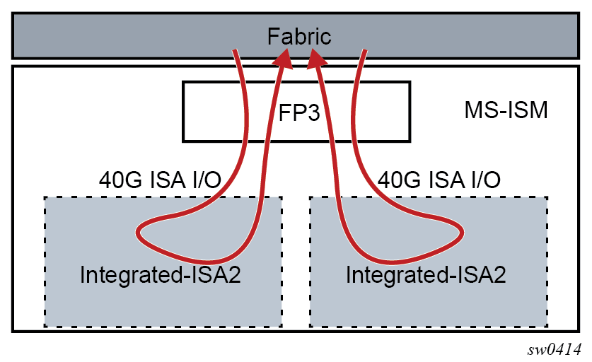
The Multiservice Integrated Services Module (MS-ISM) card contains two ISA2 processing modules providing increased packet processing throughput and scale compared to the MS-ISA platform. Each ISA2 processing module supports a 40G datapath for packet processing; as with ISA1, the actual throughput varies by function. The processed rate (up to 40 Gb/s) is the sum of the upstream and downstream rates (for example, 10 Gb/s up and 30 Gb/s down, or 20 Gb/s up and 20 Gb/s down).
The IOM base card is an imm-2pac-fp3 with two embedded positions for ISA2s. Hot swap or field replacement of the ISA2s within an MS-ISM assembly is not supported. IMM cards offering 10x10GE media plus one ISA2, or 1x100GE media plus one ISA2.
The following shows the ISA2 processing modules in the MG-ISM card.

The MS-ISA2 remains as a common base hardware assembly to be used as a generic CPU processing platform for multiple applications. The functions supported on the MS-ISA2 and MS-ISM include the following software based capabilities:
Application Assurance (AA)
Tunnel (IPsec, GRE)
Broadband (NAT, LNS)
Video (FCC, RET)
ESA overview
An Extended Services Appliance (ESA) is a server that attaches to a host 7750 SR over standard system interface ports, and which has one to four Virtual Machine (VM) instances to perform multiservice processing. The ESA provides packet buffering and processing and is logically part of the router system. The ESA 100G-2 includes one 20-core Intel fourth generation (Sapphire Rapids) 4416+ processor and 128 GB of memory. The ESA 400G (Revision BA) includes two 32-core Intel fourth generation (Sapphire Rapids) 6438N processors and 512 GB of memory.
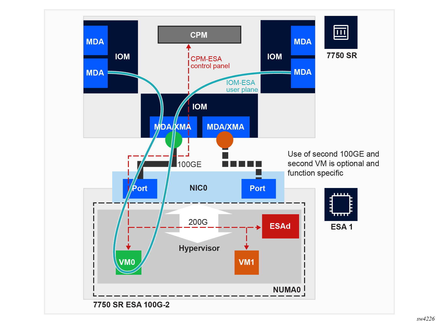
The 7750 SR control plane (CP) communicates with the ESA over one of the ESA ports. The 7750 SR CPM loads the ESA software, boots the ESA server, and installs a hypervisor with an ESA daemon (ESAd) to manage ESA chassis-level functions, such as hardware monitoring and interconnect reachability. After this process is complete, the ESAd is ready to load guest ESA-VMs. ESA-VMs are configured by the 7750 SR CPM based on the configured ESA-VM parameters in SR OS. The ESA-VMs communicate directly with the 7750 SR control plane using the port configured for use by each ESA-VM. After the ESA-VMs are brought up, they handle user plane traffic, which is forwarded from the 7750 SR user plane over the IOM or XMA interconnect ports to and from each ESA-VM via the ESA ports used by each ESA-VM.
The following figure displays the ESA-VMs communicating with the 7750 SR control plane using the port configured for use by each ESA-VM. ESA-VMs never communicate in the control plane or user plane directly with each other within an ESA. All communication takes place via the 7750 SR. Communication for an ESA 400G is not shown in the following figure, but functions similarly to the ESA 100G-2.

The ESA processing rate is the sum of the upstream and downstream rates (for example, 80 Gb/s up and 20 Gb/s down, or 50 Gb/s up and 50 Gb/s down).
The ESA 100G-2 hardware can support up to 100 Gb/s of throughput processing, and the ESA 400G up to 400 Gb/s of processing. However, the maximum ESA ingress and egress throughput varies depending on the buffering and processing demands of a specific application.
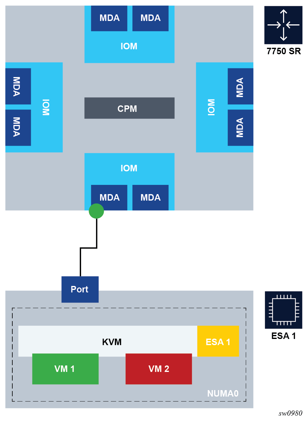
The following figure shows an ESA connected to a 7750 SR.

A direct local fiber connection must be used to connect an ESA port to a 7750 SR port. As with other MDAs and ISAs, all communication passes through the 7750 SR IOM, making use of the network processor complex on the host IOM for queuing and filtering functions.
The ESA 100G-2 includes one Mellanox Connect X6 2-port 100 Gb/s NIC with QSFP28 optics connectors. Each NIC has a maximum 200 Gb/s throughput per NIC, but, depending on the ESA-VM function used, the CPU capacity of the ESA 100G-2 limits the number of useful links to one 100 Gb/s port. One or both of the two ESA NIC ports can be used to connect to the 7750 SR port.
The ESA 400G includes two Mellanox Connect X6 2-port 100 Gb/s NIC with QSFP28 optics connectors. Each NIC has a maximum 200 Gb/s throughput per NIC, and any of the four ESA NIC ports can be used to connect to the 7750 SR port.
The following 7750 SR-to-ESA port speeds are supported:
-
100GE (using QSFP28 optics in both the 7750 SR and ESA)
-
40GE (using QSFP+ optics in both the 7750 SR and ESA)
-
25GE (using a QSFP28 - SFP28/SFP+ Adapter and SFP28 optics in both 7750 SR and ESA)
-
10GE (using a QSFP28 - SFP28/SFP+ Adapter and SFP+ optics in both 7750 SR and ESA)
ESA 400G performance may be enhanced by configuring up to four ESA-VMs for a single ESA across two CPUs. The two ESA NICs each connect to only one NUMA cell (CPU socket). For each ESA-VM, reserve at least one port for 7750 SR interconnect. The most common ESA 400G deployment scenarios are as follows:
-
one port and one ESA-VM – one port per NIC and one ESA-VM per CPU socket
-
two ports and two ESA-VMs – one port per NIC and one ESA-VM per CPU socket to ensure maximum port and ESA VM performance
-
four ports and four ESA-VMs – two ports per NIC and two ESA-VMs per CPU socket for maximum performance and density
Ports for an ESA may be from the same or from different IOMs, XMAs, or MDAs. Any combination of supported port speeds may be used on an ESA. If at least one host-port between the 7750 SR and the ESA is up, the ESA instance stays up.
An ESA-VM must be associated with one specific 7750 SR port. One physical 7750 SR port can be used by multiple VMs within an ESA. ESA-VMs may be configured as different types or the same type.
As each ESA-VM may only be associated with one 7750 SR port, LAG cannot be used between ports to an ESA. ESA-to-7750 SR link resilience is handled by provisioning more VM instances than the processing requires (using the ISA group N+1 redundancy model). Functional sparing capacity is also handled by provisioning more VM instances than required.
Each ESA is managed by one 7750 SR. The ESA software (hypervisors.tim file, located on the active CPM from the 7750 SR host) can only be instantiated by a 7750 SR and cannot be instantiated in any other virtualized environment. Creation, configuration, deletion, resource allocation, and upgrade of an ESA-VM are controlled by the 7750 SR CPM.
7750 SR system LLDP must be enabled for ESA use, as LLDP is used to verify connectivity between the configured 7750 SR ESA host-ports and the matching configured ESA port for an ESA-VM. To set up an ESA in a 7750 SR system, complete the following actions in any order:
-
Install the ESA hardware in a rack, then apply power to the ESA hardware.
-
Connect the ESA hardware to a compatible 7750 SR chassis, IOM, or MDA using the appropriate optics.
-
From the 7750 SR, configure ESA host and ESA-VM ports; see Configuring an ESA with CLI.
See the 7750 SR ESA Chassis Installation Guide for more information about the first two items in the preceding list.
The ESA hardware is then booted by the 7750 SR CPM and available resources are discovered by the 7750 SR. ESA-VMs are configured as a type and size (number of cores and amount of memory). ESA-VM types include services that also run on ISAs, thereby providing a virtualized ISA function as an ESA-VM within the 7750 SR system and as part of an ISA group. An ISA group can only contain physical ISAs or ESA-VMs. Traffic for an ESA-VM enters the 7750 SR and is forwarded to the ESA-VM in a manner identical to that of a traditional ISA.
Multiple ESAs may be configured per IOM and per system as needed for scale.
ESA interconnect CRC monitoring may be used to monitor the interconnect hardware performance, and optionally, administratively disable the ESA host port in the case of hardware errors on the line card or the port used as an ESA host port. This allows the following:
- crossing a signal degrade (SD) threshold raises a log event
- crossing the configured signal failure (SF) threshold causes the router ESA port to enter an operational state of down when the router side detects the SF, or the port is shut down when the ESA detects the SF
- configurable CRC error rates as the threshold of errors within a configurable window of time
The 7750 SR Ethernet port and ESA port CRC monitoring are independently configured. The 7750 SR host port CRC monitoring is configured using the configure port ethernet crc-monitoring command, and the ESA port CRC monitoring is configured using the configure esa host-port crc-monitoring command.
ESA 100G-2 and 400G provide CLI, SNMP, and YANG support for the following hardware monitoring states:
-
ESA health – unknown, OK, degraded, or critical
-
PSU health – unknown, OK, degraded, or critical
-
Fan redundancy – unknown, redundant, non-redundant, or failed-redundant
-
Fan health – unknown, OK, degraded, or critical
-
Power supply mismatch – true or false
-
Power supply redundancy – unknown, redundant, non-redundant, or failed-redundant
-
Temperature health – unknown, OK, degraded, or critical
ESA hardware monitoring events and states are integrated into the SR OS system facility alarms.
Application Assurance hardware features
AA system support
The Application Assurance Integrated Services Adapter (AA ISA) is a resource adapter, which means that there are no external interface ports on the AA ISA itself. Similarly, ESAs only do processing functions for traffic on the ESA interconnect ports to the SR system. Traffic on the SR system is forwarded to ISAs or ESA from any other IOMs on a system in which the AA ISA or ESA is installed, with a divert mechanism used to switch traffic internally to the AA ISA or ESA-VM.
See the SR OS R24.x.Rx Software Release Notes for information about the ESA platform support.
The following table describes Application Assurance support on the 7750 SR and 7450 ESS.
| System | AA on MS-ISM | AA on MS-ISA2 |
|---|---|---|
7750 SR-12 |
Yes |
Yes |
7750 SR-12e |
Yes |
Yes |
7750 SR-7 |
Yes |
Yes |
| 7750 SR-1e | No |
Yes |
| 7750 SR-2e | No |
Yes |
| 7750 SR-3e | No |
Yes |
7450 ESS-12 |
Yes |
Yes |
7450 ESS-7 |
Yes |
Yes |
Host IOM support for AA on ISAs
The AA MS-ISA2 is supported on IOM4-e, IOM4-e-B, IOM4-e-HS, and on 7750 SR-1e, 7750 SR-2e, and 7750 SR-3e (IOM-e). The MS-ISM versions contain one or two ISA2s embedded on a IMM card.
Each IOM can support a maximum of two AA ISA2 modules. To maximize AA ISA redundancy, deployment of AA ISAs on separate host IOMs is recommended as it provides IOM resilience. Traffic from any supported IOM (for example, IOM4-e, a fixed port IOM (IMM)) can be diverted to an AA ISA host IOM.
The MS-ISA2 is field replaceable and supports hot insertion and removal. An SR system can support up to 15 active ISA2s for AA, each providing up to 40 Gb/s processing and 600 Gb/s total per system.
AA ISA software upgrades are part of the ISSU functionality. Upgrades to AA ISA software, for example to activate new protocol signatures, do not impact the second MDA slot for the IOM carrying the AA ISA, nor do upgrades impact the router itself (for example a new AA ISA software image can be downloaded without a need to upgrade other software images).
Host IOM support for AA on ESAs
ESA port connectivity is supported on most FP3-based IOMs and all FP4-based (or later) cards. For a list of supported platforms or cards, contact your Nokia representative.
An SR system can support up to 15 active and one standby ESA-VMs for AA.
AA ESA-VM software upgrades are part of the ISSU functionality. Upgrades to AA software, for example to activate new protocol signatures, do not impact other ESA-VMs on the same ESA or on other traffic on the same IOM, nor do upgrades impact the router itself (for example, a new AA software image can be downloaded to an ESA-VM without a need to upgrade other software images).
The ESA version must match the build release version of the host IOM.
Configuring an ESA with CLI
This section provides information to configure an ESA using the CLI from a 7750 SR. It is assumed that the user is familiar with the basic concepts of configuring policies.
Provisioning an ESA and ESA-VM
Use the commands in the following context to provision an ESA.
configure esaThe following example displays an ESA containing both a VM-type AA and a VM-type BB.
MD-CLI
[ex:/configure esa 1]
A:admin@node-2# info
    admin-state enable
    description "ESA for AA-BB"
    host-port 7/1/c6/1 { }
    vm 1 {
        admin-state enable
        description "Application-Assurance ISA"
        host-port 7/1/c6/1
        vm-type aa
        cores 12
        memory 20
    }
    vm 2 {
        admin-state enable
        description "Broadband ISA"
        host-port 7/1/c6/1
        vm-type bb
        cores 9
        memory 40
    }
classic CLI
A:node-2>config>esa$ info
----------------------------------------------
        description "ESA for AA-BB"
        host-port 7/1/c6/1
        vm 1 create
            description "Application-Assurance ISA"
            host-port 7/1/c6/1
            vm-type aa
            cores 12
            memory 20
            no shutdown
        exit
        vm 2 create
            description "Broadband ISA"
            host-port 7/1/c6/1
            vm-type bb
            cores 9
            memory 40
            no shutdown
        exit
        no shutdown
----------------------------------------------
Use the following command to display information about the provisioned ESAs.
show esa===============================================================================
Extended Services Appliance Summary
===============================================================================
ESA Description Admin Oper Health
State State State
-------------------------------------------------------------------------------
1 ESA for AA-BB up up OK
===============================================================================
* indicates that the corresponding row element may have been truncated.Use the following command to display detailed information about the provisioned ESAs.
show esa detail===============================================================================
ESA 1
===============================================================================
Description : ESA for AA-BB
Admin State : up
Operational State : up
Oper flags : none
IOM Host Port(s) : 2/x1/1/c9/1
: 2/x1/1/c10/1
Hardware Health
Overall Status : OK
Power Supply 1 Status : OK
Power Supply 2 Status : OK
Power Supply Redundancy : Redundant
Power Supply Mismatch Stat*: No-Mismatch
Fan Status : OK
Fan Redundancy : Redundant
Temperature Status : OK
Hardware Data
System manufacturer : HPE
System product name : ESA 400G AC
System part number : 3HE17699BA
System serial number : MXQ3210CRM
Software Version : TiMOS-H-23.10.R1 hypervisor/esa Copyright (c)
2000-2023 Nokia. All rights reserved. All use
subject to applicable license agreements.
Built on Thu Oct 26 20:12:19 UTC 2023 by
builder in /builds/2310B/R1/panos/hypervisors
Time of last boot : 2023/12/01 21:32:05 UTC
Total Cores available : 62
Total Cores allocated : 30
Total Cores remaining : 32
Total Memory available : 478 GB
Total Memory allocated : 128 GB
Total Memory remaining : 350 GB
Performance enabled : yes
Export restricted : no
NUMA Cell Topology
NUMA Cell 0
Cores Available : 31
Cores Allocated : 30
Cores Remaining : 1
Memory Available : 239 GB
Memory Allocated : 128 GB
Memory Remaining : 111 GB
Socket : 0
Host Port(i/f) : 2/x1/1/c9/1 (eth0)
Host Port(i/f) : 2/x1/1/c10/1 (eth1)
NUMA Cell 1
Cores Available : 31
Cores Allocated : 0
Cores Remaining : 31
Memory Available : 239 GB
Memory Allocated : 0 GB
Memory Remaining : 239 GB
Socket : 1
===============================================================================
* indicates that the corresponding row element may have been truncated.
===============================================================================
ESA VMs
===============================================================================
ESA VM VM Type Cores Memory Host-Port Admin Oper
(GB) State State
-------------------------------------------------------------------------------
1 1 aa 15 64 2/x1/1/c9/1 up up/active
1 2 bb 15 64 2/x1/1/c10/1 up up
===============================================================================