System Initialization and boot options
This section describes the system initialization and boot option process.
Boot process
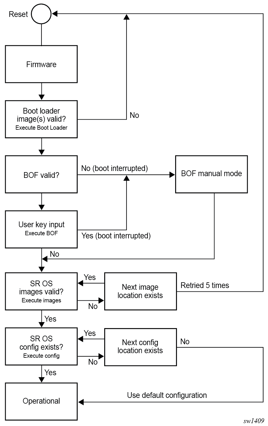
The router startup process begins after a reset or power cycle with the firmware initializing the hardware before executing the Boot Loader images. The Boot Loader then executes the boot options file (BOF) to load the SR OS software image and configuration. The BOF file contains system initialization commands including the software image and configuration locations.
SR OS Boot Loader, software images, and configuration files are stored in storage media cards referred to as CF in the system. See Storage devices for more information on the type of storage supported for each platform.
The following diagram describes the system boot process from the firmware up to the SR OS image and configuration file.
Boot Loader
The Boot Loader executes the initialization command options from the BOF to load the software images and configuration file.
The Boot Loader phase can be manually interrupted even if the BOF is present by pressing any key on the console connected to the console port. This is done by typing sros and pressing the Enter key within 30 seconds to enter the BOF manual mode. This mode allows the configuration of the BOF system initialization commands manually and overwrites the existing BOF file, if present.
Different Boot Loader images are used depending on the CPM control module:
- 7450 ESS, 7750 SR, 7750 SR 7s/14s, 7950 XRS
- boot.ldr is the Boot Loader image that executes the BOF file before loading SR OS TiMOS software images and configuration
- boot.ldr must be located at the root directory of the CF3 card (for systems using boot.ldr)
- 7750 SR-1x-48D, SR-1x-92S, SR-1-24D, SR-1-48D, SR-1-46S, SR-1-92S, SR-1se, and
SR-2se
-
bootx64.efi is the original Boot Loader image located in /EFI/BOOT
-
bootx64.efi executes the other images in /EFI/BOOT/x86_64 before executing the BOF file and loading SR OS TiMOS software images and configuration
-
Boot Option File
The BOF file (bof.cfg) must be located at the root of the CF3 card directory and contains various system initialization commands including:
- management ethernet port (speed, duplex, IP address, static routes)
- console port speed
- software image locations
- configuration file locations
- BOF and configuration file encryption settings
- BOF password
- system profile
- wait time
- Zero Touch Provisioning
- licenses
- persistency
BOF Manual Mode
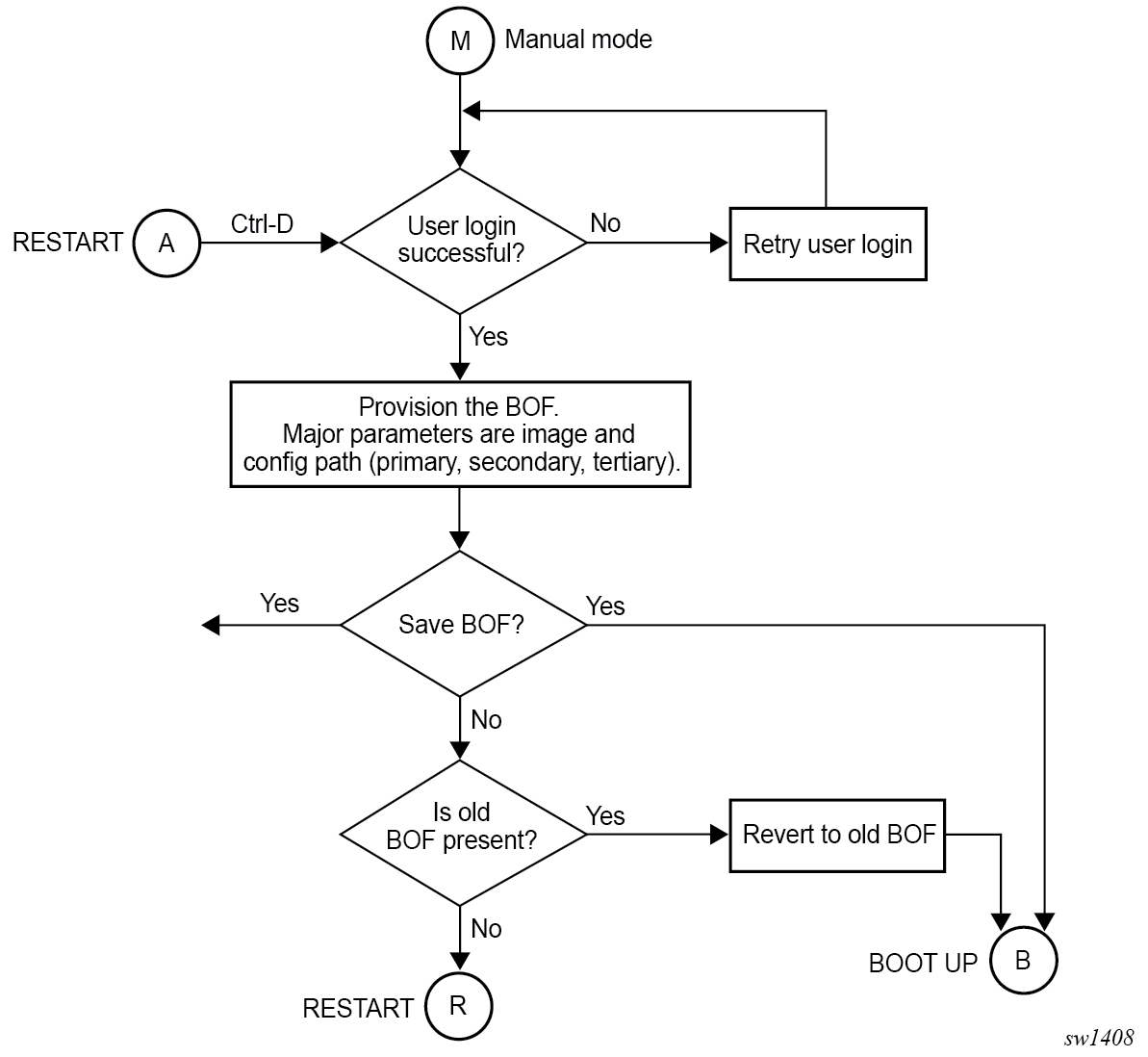
The system enters the BOF manual mode if the BOF is not present in the CF3 card or if the user interrupts the Boot Loader phase and requires access to the console port for configuration.
After the manual BOF configuration is completed and saved, a bof.cfg file with the new configured command options is created in the CF3 card and used for subsequent reboots. The Boot Loader image then processes the new BOF command options to boot the system.
This process is described in the following diagram.
Software and configuration
The software image and configuration file location are configured in the BOF.
Up to three locations, local or remote, can be configured for the software image and configuration file defined as primary image, secondary image, tertiary image, primary config, secondary config and tertiary config in the BOF.
Before loading the configuration, the software first attempts to read the license file if one has been included in the BOF. If a license file is found, it is activated. If there are any issues with the activation, a log event is raised, and the startup processing continues with the reading of the configuration file.
The following usage guidelines apply:
- The primary, secondary, and tertiary image locations must have the same version of software. If the secondary or tertiary image are configured with an older software image, this may result in a failure to load the configuration file as it may contain commands only applicable to the more recent release.
- Similarly, the secondary and tertiary configuration files, if used, should be saved with the same version of software as the software executed on boot as it can result in a failure to load the configuration file otherwise.
- In model-driven configuration mode with incremental saved configuration files enabled, the primary configuration location supports complete and incremental saved configuration files. The secondary and tertiary configuration locations support complete saved configuration files. The user must ensure that complete saved configuration files are stored at both locations.
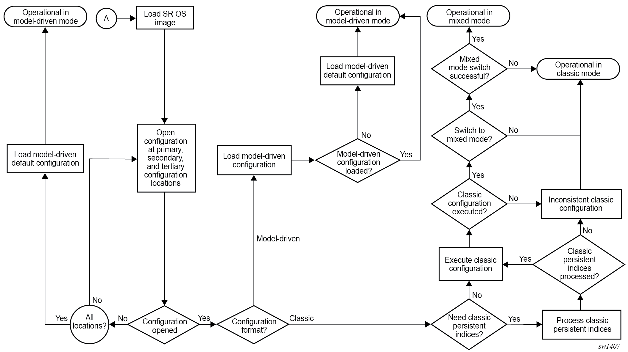
The following diagram provides additional details on the boot process differences between classic and MD CLI configuration file processing.
Management interface configuration modes
The system can operate in different management interface configuration modes, which affect the CLI and network management protocols that can be used to configure the system. When the system boots and loads the configuration file, the configuration mode is set as follows:
- The default configuration mode is model-driven and a model-driven
configuration file format is loaded.
The command option of configure system management-interface configuration-mode in the configuration file must not be classic or mixed.
- If the configuration file has exit all as the first executable
line, the configuration mode is set to classic and a classic
configuration file format is loaded. Lines beginning with a number sign character
(#) are ignored.
- The configuration mode may be changed to mixed if the value of configure system management-interface configuration-mode is mixed in the configuration file.
- The command option of configure system management-interface configuration-mode in the configuration file must not be model-driven.
See "Management interface configuration modes" in the 7450 ESS, 7750 SR, 7950 XRS, and VSR System Management Guide for more information.
Initial installation and software update
The following recommendations apply to all Extensible Firmware Interface (EFI) boot loader systems:
- When installing a new CF3 SD card for the first time, all files including the
installer files listed in the storage card content section of the respective
platforms must be present in the SD card, and the SD card must be in FAT32 format.
See Storage card content for more information. The first boot of
the system on a new CF3 SD card initializes the software and partitions on the SD
card. Two hidden partitions are created for internal use, the third partition is for
operator use and is visible from TiMOS as CF3:.Note: An SD card containing necessary files and partitions can be hot-plugged into an operational router; replacing the CF3 SD card with a brand new SD card, however, requires a reboot for the system to initialize the card.
- When upgrading or changing the software on a system that has previously booted correctly, the OS installer files in the /EFI directory can be omitted from the SD card content and are automatically updated by the system on upgrade to the new SR OS TiMOS software version.
- The bof.cfg BOF file must be in the CF3:\ directory.
- The boot.ldr file is not required in the CF3:\ directory.
The following recommendations apply to all boot.ldr boot systems:
- The boot.ldr and bof.cfg files must be present at the root of the CF3:\ directory.
- When upgrading or changing the software, the corresponding boot.ldr image version must also be updated in the CF3:\ directory.
- The /EFI content is not required in the CF3:\ directory.
Storage card content
SR OS software downloaded from the Nokia support website includes boot and operating system images for all platforms. This section describes the required storage media card directory and filenames on a per-platform basis to clarify which files and directory apply to which platform.
The primary copy of the SR OS software is located on a Compact Flash or SD card which is shipped with each software license agreement. The content of this storage media card can differ depending on the platform.
Configurations and executable images can be stored in any storage media supported by the platform while the boot loader images and boot option file must be installed in the storage media card slot 3 (CF3:).
See the Storage devices section for the list of storage media names, locations, and support for each SR OS platform.
7750 SR-1x-48D, SR-1x-92S, SR-1-24D, SR-1-48D, SR-1-46S, SR-1-92S, SR-1se, and SR-2se
When installing a new storage media card into the system for the first time, ensure that the media card contains only the software files shipped by Nokia.
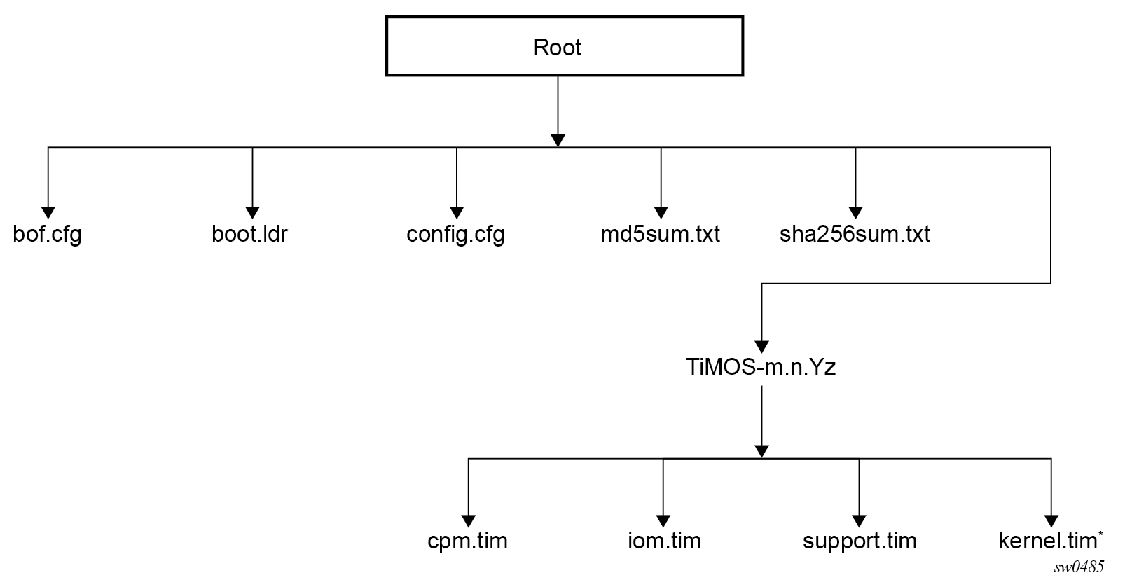
The following figure shows the required storage media card directory structure and filenames.
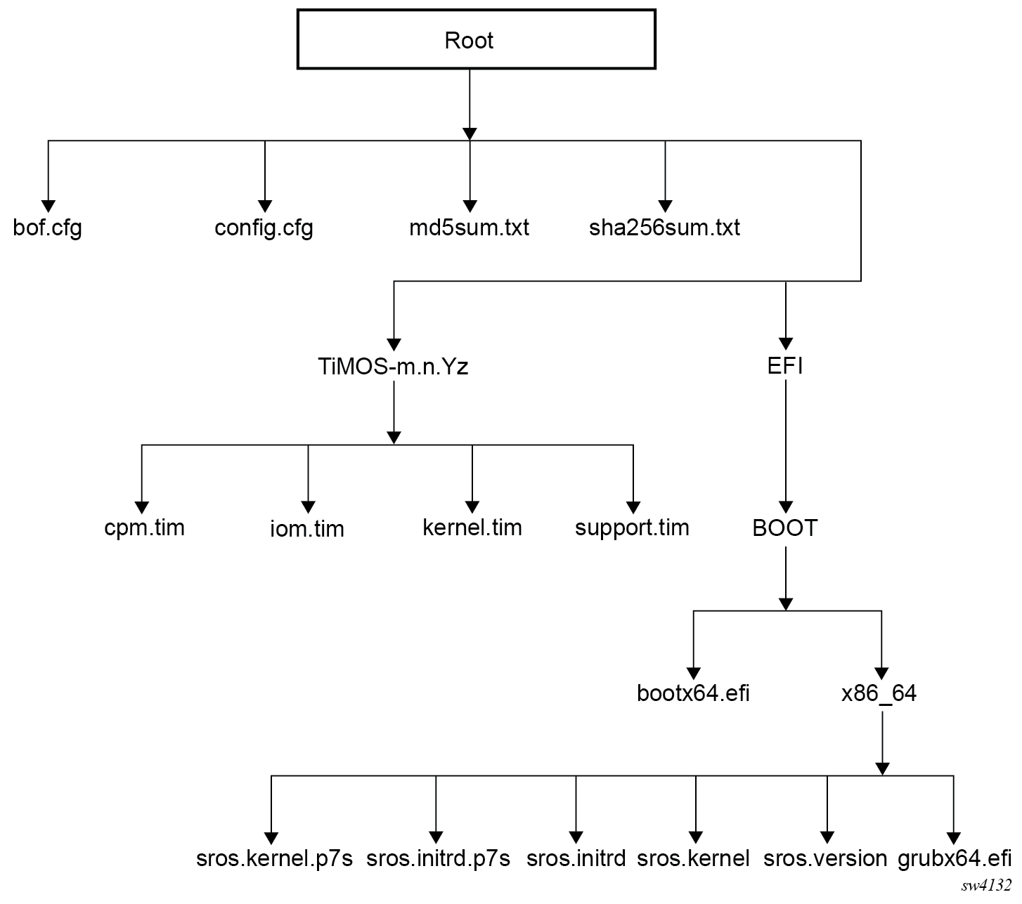
The following files are present on the storage media card:
-
bof.cfg – boot option file
-
config.cfg – default configuration file
-
md5sum.txt – MD5 checksum file
-
sha256sum.txt – SHA256 checksum file
-
TiMOS-m.n.Yz:
m – signifies a major release number
n – signifies a minor release number
Y: A signifies an alpha release
B – signifies a beta release
M – signifies a maintenance release
R – signifies a released software
z – signifies a version number
-
cpm.tim – CPM image file
-
iom.tim – IOM image file
-
kernel.tim – host operating system
- support.tim – required data for SR OS .tim files
-
The following files and folder structure under /EFI should only be included if the system is booted with a new storage media card installed for the first time:
-
EFI:
-
BOOT:
-
bootx64.efi – EFI file; Boot Loader
-
x86_64:
– sros.initrd – OS installer file; installer rootfs
– sros.kernel – OS installer file; installer kernel
– sros.version – OS installer file; installer version
– grubx64.efi – EFI file; GRUB boot loader
-
-
7450 ESS, 7950 XRS, 7750 SR 7/7s/12/12e/14s, SR-a, SR-e, and SR-2s
The following figure shows the required storage media card directory structure and filenames.
The following files are on the storage media card:
-
bof.cfg – boot option file
-
boot.ldr – bootstrap image file
-
config.cfg – default configuration file
-
md5sum.txt – MD5 checksum file
-
sha256sum.txt – SHA256 checksum file
-
TiMOS-m.n.Yz:
m – signifies a major release number
n – signifies a minor release number
Y: A – signifies an alpha release
B – signifies a beta release
M – signifies a maintenance release
R – signifies a released software
z – signifies a version number
-
cpm.tim – CPM image file
-
iom.tim – IOM image file
-
support.tim – required data for SR OS .tim files
-
kernel.tim – host operating system, required for 7750 SR-7s and 7750 SR-14s only
-
7750 SR-1 and SR-1s
The following figure shows the required storage media card directory structure and filenames.
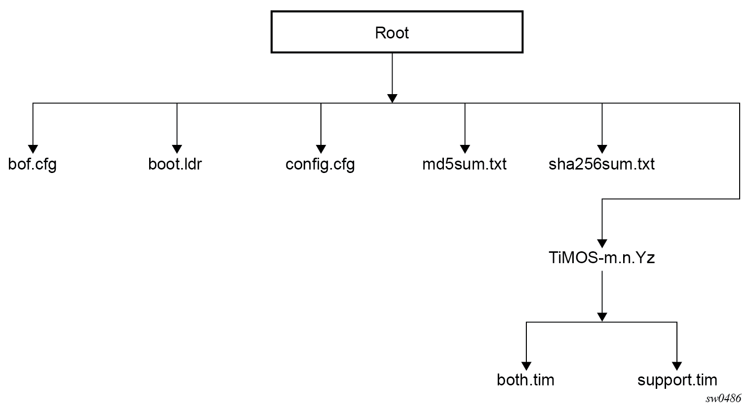
The following files are present on the storage media card:
-
bof.cfg – boot option file
-
boot.ldr – bootstrap image file
-
config.cfg – default configuration file
-
md5sum.txt – MD5 checksum file
-
sha256sum.txt – SHA256 checksum file
-
TiMOS-m.n.Yz:
m – signifies a major release number
n – signifies a minor release number
Y: A – signifies an alpha release
B – signifies a beta release
M – signifies a maintenance release
R – signifies a released software
z – signifies a version number
-
both.tim – CPM and IOM image file
-
support.tim – required data for SR OS .tim files
-
ISA and ESA applications
The following images must also be present in the SR OS software TiMOS-m-n-Yz directory depending if ESA or Application Assurance are used:
- hypervisors.tim: hypervisor image for the ESA cards
- isa-aa.tim: Application Assurance software image
Persistent indices in classic and mixed configuration mode
The BOF persist parameter specifies whether the system should preserve system indices when the configuration is saved. During a subsequent boot, the index file is read along with the configuration file. As a result, a number of system indices are preserved between reboots, including the SNMP interface index, LSP IDs, path IDs, and so on. If persistence is not required and the configuration file is successfully processed, the system becomes operational. If persist is required, a matching config.ndx file must be successfully processed before the system can become operational. Configuration and index files must have the same filename prefix such as config.cfg and config.ndx and are created at the same time when an admin save command is executed. Note that the persistence option must be enabled to deploy a Network Management System (NMS) using SNMP. The default is off.
BOF and configuration file encryption
In cases where the platform is not installed in a physically secure location, the user can encrypt the BOF and the configuration file to halt or hinder interpretation of the file content.
By default, the BOF and configuration files are not encrypted. When encryption is enabled for either file and a change is saved , the original file is moved to filename.1 and the encrypted file becomes the new filename.cfg.
When the BOF is encrypted on the Compact Flash, the BOF interactive menu can be used during node startup to access the file and modify BOF fields. To prevent unauthorized modification of the BOF using the BOF interactive menu, configure a password using the following command:
- MD-CLI
bof configuration password - classic
CLI
bof password
The BOF interactive menu is accessible only when the configured password is entered. If the correct password is not entered in 30 seconds, the node reboots.
See Configuring BOF encryption for information about configuring BOF encryption. See Configuring the BOF interactive menu password for information about configuring the BOF interactive menu password. See Configuring configuration file encryption for information about configuring the configuration file encryption.
System profiles
System profiles provide flexibility when using line cards based on FP4 and later generations by supporting different system capabilities. The system profile is defined in the BOF and is used by the system when it is next rebooted. Contact your Nokia representative for system profile information.
The following system profiles are supported:
profile none
This profile represents the existing system capabilities and allows hardware based on FP3 and later generations to coexist within a system. This profile is indicated by the omission of the profile parameter in the BOF.
profile A
This profile is primarily targeted at subscriber services and Layer 2 and 3 VPN business services. Use the following command to configure the profile:- MD-CLI
bof system profile profile-a - classic
CLI
bof system-profile profile-a
- MD-CLI
profile B
This profile is primarily targeted at infrastructure routing, core, peering, and DC-GW applications.
System profiles profile-a and profile-b support only line cards based on FP4 and later generations. Provisioning FP2- or FP3-based line cards is prohibited when the system profile is set to profile-a or profile-b. If FP2- or FP3-based card types are present in the boot configuration when using these profiles, the boot sequence aborts the loading of the configuration file when it encounters their configuration.
When changing between system profiles, it is mandatory to remove all configuration commands for features that are not supported in the target system profile before rebooting the system, otherwise the reboot fails at the unsupported configuration command on startup.
On 7750 SR-1 and 7750 SR-s systems, the following conditions apply about the profile parameter:
The parameter should be configured to either profile-a or profile-b.
If the parameter is omitted, profile profile-a is used by the system.
If the parameter is configured to an invalid value, it is ignored and profile profile-a is used by the system.
On 7750 SR-7-B/12-B/12e and 7950 XRS-20/20e systems, the following conditions apply about the profile parameter:
The default system profile is none when the parameter is omitted.
-
The parameter can be configured to either profile-a or profile-b, in which case only FP4-based line cards are supported.
-
If the parameter is configured to an invalid value, it is ignored and profile none is used by the system.
On all other systems, the following conditions apply about the profile parameter:
These systems must use profile none (the existing system capabilities). As a result, the parameter must not be configured.
If the parameter is configured to profile-a or profile-b, the system boots, allowing access using the console and CPM management interface, but FP2-based and FP3-based line cards cannot be provisioned; if these card types are present in the boot configuration, the boot sequence aborts loading the configuration file when it encounters their configuration. This issue can be corrected by removing the parameter and rebooting the system.
If the parameter is configured to an invalid value, it is ignored and profile none is used by the system.
configure redundancy synchronize boot-envWhen performing a minor or major ISSU software upgrade on dual CPM systems, it is important that the system profile in the BOF on both the active and standby CPM is the same and has a value supported on the pre-upgrade software release. If the standby CPM happened to have a system profile which is only supported in the post-upgrade release, the active CPM reboots the standby and keeps it down because of a system profile mis-match.
Use the following command to display the BOF system profile:
- MD-CLI
admin show configuration bof | match profile - classic
CLI
show bof | match system-profile
The BOF system profile used by the system when it booted can be seen in the boot messages (using the show boot-messages command), which display the BOF read when rebooting.
show chassis | match "System Profile"Use the following command to configure the system profile:
- MD-CLI
bof system profile - classic
CLI
bof system-profile
FIPS-140-2 mode
The 7750 SR includes a configurable parameter in the bof.cfg file to make the node run in FIPS-140-2 mode. When the node boots in FIPS-140-2 mode, the following behaviors are enabled on the node:
The node performs an HMAC-SHA-256 integrity test on the software images .tim files.
The node limits the use of encryption and authentication algorithms to only those allowed for the associated FIPS-140-2 certification of the 7750-SR.
Cryptographic module startup tests are executed on the CPM when the node boots to ensure the associated approved FIPS-140-2 algorithms are operating correctly.
Cryptographic module conditional tests are executed when required during normal operation of associated when using FIPS-140-2 approved algorithms.
When configuring user-defined encryption or authentication keys, the CLI prompts for the key to be re-entered. For keys entered in hash format, for example, the key must be re-entered in hash format, followed by the appropriate hash keyword. If the re-entered key does not match the original, the CLI command is canceled. This affects several protocols and applications.
To support FIPS-140-2, an HMAC-SHA-256 integrity check is performed to verify the integrity of the software images. The hmac-sha256.txt file, containing the hmac-sha-256 signature, is included in the TIMOS-m.n.Yz software bundle.
During the loading of the cpm.tim or both.tim, an HMAC-SHA-256 check is performed to ensure that the calculated HMAC-SHA-256 of the loaded image matches that stored in the hmac-sha256.txt file.
The HMAC-SHA-256 check is performed on the data loaded from the .tim file. Note that when configuring the primary-image, secondary-image and tertiary-image, the hmac-sha256.txt file must exist in the same directory as the .tim files. If the load has been verified correctly from the HMAC-SHA-256 integrity check, the load continues to start up as normal. If the load is not verified by the HMAC-SHA-256 integrity check, the image load fails.
After the HMAC-SHA-256 integrity check passes, the nodes continue their normal startup sequence including reading the config.cfg file and loading the configuration. The config.cfg file used to boot the node in FIPS-140-2 mode must not contain any configuration that is not supported in FIPS-140-2 mode. If such configuration is present in the config.cfg file when the node boots, the node loads the config.cfg file until the location of the offending configuration and then halt the configuration at that point. Upon a failure to load the config.cfg file, a failure message is printed on the console.
Enabling FIPS-140-2 restricts the ability to configure and use cryptographic algorithms and functions that are not FIPS approved. FIPS-140-2 impacts the ability to configure SSH, SNMP and certificates. See the 7450 ESS, 7750 SR, 7950 XRS, and VSR System Management Guide for details of FIPS-140-2 related items.
In addition, signature algorithms of the following combinations only are approved for FIPS:
FIPS-140 Approved - Digital Signature Standard (DSS)
DSA
RSA
ECDSA
FIPS-140 Approved - Secured Hash Standard (SHS)
SHA-1
SHA-224
SHA-256
SHA-384
SHA-512
Any other combination is not supported in FIPS mode. Using other FIPS signature algorithms in certificates affecting IPsec can cause tunnels to fail. Restrictions to cryptographic algorithms are listed in the 7450 ESS, 7750 SR, 7950 XRS, and VSR System Management Guide.
Lawful Intercept
Lawful Intercept (LI) describes a process to intercept telecommunications by which law enforcement authorities can unobtrusively monitor voice and data communications to combat crime and terrorism with higher security standards of lawful intercept capabilities in accordance with local law and after following due process and receiving correct authorization from competent authorities. The interception capabilities are sought by various telecommunications providers.
As lawful interception is subject to national regulation, requirements vary from one country to another. -This implementation satisfies most national standard’s requirements. LI is configurable for all service types.
Configuring boot options file with CLI
This section provides information about configuring BOF parameters with CLI.
Basic BOF configuration
The parameters which specify the location of the image filename that the router tries to boot from and the configuration file are in the BOF.
The most basic BOF configuration should include the following:
-
primary address
-
primary image location
-
primary configuration location
The following is an example of a basic BOF configuration.
MD-CLI
[]
A:admin@node-2# admin show configuration bof
# TiMOS-B-22.2.R1 both/x86_64 Nokia 7750 SR Copyright (c) 2000-2022 Nokia.
# All rights reserved. All use subject to applicable license agreements.
# Built on Sat Feb 26 15:31:00 PST 2022 by builder in /builds/c/222B/R1/panos/main/sros
# Configuration format version 22.2 revision 0

# Generated 2022-03-07T17:08:41.4+00:00 by admin from Console

bof {
    configuration {
        primary-location "cf3:\config.cfg"
    }
    console {
        speed 115200
    }
    dns {
        domain "example.com"
        primary-server 10.251.72.68
        secondary-server 10.251.10.29
    }
    image {
        primary-location "cf3:\timos\"
    }
    li {
        local-save false
        separate false
    }
    license {
        primary-location "cf3:\license.txt"
    }
    port "management" {
        autonegotiate true
    }
    router "management" {
        interface "management" {
            cpm active {
                ipv4 {
                    ip-address 192.168.189.52
                    prefix-length 24
                }
            }
            cpm standby {
            }
        }
        static-routes {
            route 192.168.0.0/16 {
                next-hop 192.168.189.1
            }
            route 172.16.0.0/16 {
                next-hop 192.168.189.1
            }

        }
    }
    system {
        fips-140-2 false
        persistent-indices true
    }
}

# Finished 2022-03-07T17:09:40.4+00:00
classic CLI
A:node-2# show bof
===============================================================================
BOF (Memory)
===============================================================================
    primary-image    ftp://*:*@192.168.15.1/./images/
    primary-config   ftp://*:*@192.168.15.1/./images/dut-a.cfg
    address          192.168.189.53/16 active
    address          192.168.189.54/16 standby
    static-route     192.0.2.0/24 next-hop 192.0.2.254
    static-route     192.168.0.0/16 next-hop 192.0.2.254
    static-route     192.168.10.10/16 next-hop 192.0.2.254
    autonegotiate
    duplex           full
    speed            100
    wait             3
    persist          off
    console-speed    115200
===============================================================================
Common configuration tasks
This sections describes basic system tasks that must be performed to configure BOF.
For more information about hardware installation and initial router connections, see the specific hardware installation guide.
Searching for the BOF
The BOF should be on the same drive (cf3:) as the bootstrap image file. If the system cannot load or cannot find the BOF, the system checks whether the boot sequence was manually interrupted.
Accessing the CLI
To access the CLI to configure the software for the first time, perform the following steps:
-
When the power to the chassis is turned on, the SR OS software automatically begins the boot sequence.
-
When the boot loader and BOF image and configuration files are successfully located, establish a router connection (console session).
Console connection
To establish a console connection, you need the following:
-
An ASCII terminal or a PC running terminal emulation software set to the parameters that are shown in the following table.
-
A standard serial cable connector for connecting to an RS232 port (provides an RJ-45 connector).
Table 1. Console configuration parameter values Parameter Value Baud rate
115200
Data bits
8
Parity
None
Stop bits
1
Flow control
None
Configuring BOF encryption
The BOF contents are encrypted using AES256 and authenticated and hashed using SHA256.
Use the following command to configure BOF encryption:
- MD-CLI
bof configuration encrypt true - classic CLI
bof encrypt on
Configuring the BOF interactive menu password
Access to the BOF interactive menu can be controlled using a password.
Use the following command to configure a BOF interactive menu password:
The password can be in one of the following formats:
Configuring configuration file encryption
The configuration file contents can be encrypted using AES256 or SHA256.
Use the following command to configure a BOF file encryption key:
- MD-CLI
bof configuration encryption-key - classic CLI
bof encryption-key
When configuring an encryption key, the key can be in one of the following formats:
- a plaintext string between 8 and 32 characters; the plaintext string cannot contain embedded nulls or end with “ hash”, “ hash2”, or “ custom”Caution: When entering the encryption key in plaintext, ensure that the key is not visible to bystanders.
a hashed string between 1 and 64 characters; the selected hashing scheme can be hash, hash2, or custom
Autoconfigure
When autoconfigure is enabled, the router performs a DHCP discovery or solicit (IPv6) to get the IP address of the out-of-band (OOB) management port.
The OOB management port can support a DHCP client for IPv4, IPv6, or dual stack. For dual stack, both IPv4 and IPv6 DHCP are configured. When the offer for either of the address families arrives, the management port is configured with the IP address in the offer. Eventually, both offers arrive and the management port is configured with both address families.
When a DHCP client is configured using autoconfigure, all image and license files should be placed and loaded from the CF. The configuration file could be loaded from the network, but Nokia recommends that the config file be on the CF as well. The configuration file is not loaded until the DHCP client offer is received and programmed successfully for the management port IP address, or the DHCP client timeout is expired.
Autoconfigure restrictions
When autoconfigure is enabled, a static IP address or static route cannot be configured in the BOF.
Similarly, a DNS server cannot be configured in the BOF, and only the DNS server provided by the DHCP offer can be used to resolve URLs.
The option 15 DNS domain name is not supported. The user can configure the DNS domain in the BOF so that the domain is not blocked when autoconfigure is used. Otherwise, the user must use the absolute URL with the hostname and domain included.
DHCP discovery of MAC addresses
When autoconfigure is used on redundant CPM chassis, the DHCP discovery uses the chassis MAC address. Only the active CPM performs a DHCP discovery and not the inactive CPM. When the offer arrives, the node uses that IP and the chassis MAC as addresses for management. Consequently, the inactive CPM is not reachable by the network, because it has no separate IP address. On activity switch, the inactive CPM inherits the active IP and chassis MAC.
For non-redundant CPMs, the management port MAC is used.
IPv6 DUID
SR OS supports type 2 DUID (link local), which is set to the chassis serial number. Type 3 (enterprise) is set to the chassis MAC address. Type 1 is not supported.
For type 2 DUID, the SR OS sends the Nokia Enterprise ID as the second byte of the DUID, followed by the chassis serial number. The first byte is the DUID type code. The chassis serial number starts with capital ASCII letters, which ensures that the serial number is unique as an application ID in the SR OS IPv6 DHCP application domain.
DUID type codes are as follows:
DHCP6C_DUID_ENT_ID__IPSEC_IPV4ADDR - 1
DHCP6C_DUID_ENT_ID__IPSEC_ASN1DN - 2
DHCP6C_DUID_ENT_ID__IPSEC_FQDN - 3
DHCP6C_DUID_ENT_ID__IPSEC_USER_FQDN - 4
DHCP6C_DUID_ENT_ID__IPSEC_IPV6ADDR - 5
DHCP6C_DUID_ENT_ID__IPSEC_ASN1GN - 6
DHCP6C_DUID_ENT_ID__IPSEC_KEYID - 7
DHCP6C_DUID_ENT_ID__WLAN_GW - 8
DHCP6C_DUID_ENT_ID__AUTOBOOT - 9
DHCP6C_DUID_ENT_ID__ZTP_BOF_AUTOP - Capital letters in ASCII
IPv6 DHCP RAs
An IPv6 DHCP offer does not have an IP prefix within the offer, unlike an IPv4 DHCP offer. The IPv6 prefix is usually obtained from the IPv6 Route Advertisement (RA) arriving from the upstream router. For ZTP, SR OS is a host and assigns a /128 prefix to the IPv6 address obtained from the DHCP offer. In addition, SR OS supports the installation of IPv6 default and static routes from upstream routers using the IPv6 RA. Multiple upstream routers can respond to a route solicitation with their own RA. SR OS installs all the routes advertised by the RA. If the same route is advertised by multiple upstream routers (next hops), the SR OS installs the route with the highest preference. The SR OS does not support ECMP when the same route is advertised from multiple next hops by multiple RAs.
To ensure that all the RAs are obtained before the auto-provisioning process is started for IPv6, SR OS follows the RFC 4861 recommendation that the host (in this case SR OS) send a minimum of three route solicitations. This is to ensure that if a route solicitation is lost, at least one of the three would reach the upstream routers. Each route solicitation is followed by a 4 s timeout. If the first route solicitation is sent at T0, the second is sent at T0+4 s and the third is sent at T0+8 s. The upstream routers must respond to the route solicitation within 0.5 s. This means that the SR OS has all of the RAs and the routes within 8.5 s of the first route solicitation. Therefore, SR OS waits for a maximum of 9 s to receive all RAs.
If the DHCPv6 timeout is less than 9 s, the DHCPv6 timeout is honored even for the RA wait time. If the node has received a single RA and DHCP offer, the process is considered a success. However, it is possible that not all the RAs have arrived on the node because the node has waited less than 9 s.
Service management tasks
This section describes the service management tasks and the system administration commands.
System administration commands in the classic CLI
For more information about the supported classic CLI commands, see the 7450 ESS, 7750 SR, 7950 XRS, and VSR Classic CLI Command Reference Guide.
Use the following administrative commands to perform management tasks.
admin display-config
admin reboot
admin save
Viewing the current configuration
Use one of the following CLI commands to display the current configuration. The detail option displays all default values. The index option displays only the persistent indexes. Use the following command to display context-level information.
admin display-config
info detail
The following example shows a configuration file for the 7750 SR.
A:7750-3>admin# display-config
# TiMOS-B-22.2.R1 both/x86_64 Nokia 7750 SR Copyright (c) 2000-2022 Nokia.
# All rights reserved. All use subject to applicable license agreements.
# Built on Sat Feb 26 15:31:00 PST 2022 by builder in /builds/c/222B/R1/panos/main/sros
# Configuration format version 22.2 revision 0

# Generated MON MAR 07 16:50:13 2022 UTC

exit all
configure
#--------------------------------------------------
echo "System Configuration"
#--------------------------------------------------
system
        name "7750-3"
        contact "Fred Information Technology"
        location "Bldg.1-floor 2-Room 201"
        clli-code "abcdefg1234"
        coordinates "N 45 58 23, W 34 56 12"
        ccm 1
        exit
        snmp
        exit
        login-control
            idle-timeout 1440
            motd text "7750-3"
        exit
        time
            sntp
                shutdown
            exit
            zone UTC
        exit
        thresholds
            rmon
            exit
        exit
    exit...
...
--------------------------------------------------
echo "Redundancy Configuration"
#--------------------------------------------------
    redundancy
        synchronize boot-env
    exit
...exit all

# Finished MON MAR 07 16:50:58 2022 UTC
A:7750#
Modifying and saving a configuration
If you modify a configuration file, the changes remain in effect only during the current power cycle unless a save command is executed. Changes are lost if the system is powered down or the router is rebooted without saving.
Specify the file URL location to save the running configuration. If a destination is not specified, the files are saved to the location where the files were found for that boot sequence. The same configuration can be saved with different filenames to the same location or to different locations.
The detail option adds the default parameters to the saved configuration.
The index option forces a save of the index file.
Changing the active and standby addresses without rebooting standby CPM may cause a boot-env sync to fail.
The following command saves the BOF configuration.
A:node-2# bof save
Writing configuration to cf3:/bof.cfg ... OK
Completed.
The following command saves the system configuration.
A:node-2# admin save
Writing configuration to cf3:/config.cfg
Saving configuration ... OK
Completed.Deleting BOF parameters
You can delete specific BOF parameters. The changes remain in effect only during the current power cycle unless a save command is executed. Changes are lost if the system is powered down or the router is rebooted without saving.
Deleting a BOF address entry is not allowed from a remote session.
Use the no form of following commands to remove and save BOF configuration parameters.
bof address <ip-prefix/ip-prefix-length> [<cpm>]
bof autonegotiate
bof console-speed <baud-rate>
bof dns-domain <dns-name>
bof duplex <duplex>
bof ess-system-type
bof ip-mtu <octets>
bof li-local-save
bof li-separate
bof license-file <file-url>
bof persist {on|off}
bof primary-config <file-url>
bof primary-dns <ip-address>
bof primary-image <file-url>
bof save [<cflash-id>]
bof secondary-config <file-url>
bof secondary-dns <ip-address>
bof secondary-image <file-url>
bof speed <speed>
bof static-route <ip-prefix/ip-prefix-length> next-hop <ip-address>
bof system-base-mac <mac-address>
bof system-profile <profile>
bof tertiary-config <file-url>
bof tertiary-dns <ip-address>
bof tertiary-image <file-url>
bof wait <seconds>
A:node-2# bof save
Writing configuration to cf3:/bof.cfg ... OK
Completed.Saving a configuration to a different filename
Save the current configuration with a unique filename to have additional backup copies and to edit parameters with a text editor. You can save your current configuration to an ASCII file.
The following example shows saving a configuration to a different location.
A:node-2>admin save cf3:\testABC.cfg
Writing configuration to cf3:\testABC.cfg
Saving configuration ... OK
Rebooting
When an admin>reboot command is issued, routers with redundant CPM are rebooted as well as the XMAs, XCMs, and IOMs. Changes are lost unless the configuration is saved. Use the admin>save file-url command to save the current configuration. If no command line options are specified, the user is prompted to confirm the reboot operation.
The following example shows a reboot.
A:node-2>admin# reboot
Are you sure you want to reboot (y/n)? y
Setting the MTU value for the management port
You can configure the MTU for IP packets transmitted out the interface of the management router instance associated with the management port. The command applies to the SR OS, however, it does not necessarily apply during the boot loader processing.
The operational MTU for the port is set to the lesser of the values configured with the ip-mtu command and the management port MTU. For example, with the port MTU fixed at 1514 bytes and an Ethernet header size of 14 bytes, the MTU of the management port is 1500 bytes (the default operational IP MTU).
If the interface supports IPv6 packets, the command value must be set to 1280 or higher, in accordance with RFC 2460, Internet Protocol, Version 6 (IPv6) Specification. Use the following command to configure the MTU for IP packets transmitted out the interface of the management router instance.
bof ip-mtuSystem administration commands in the MD-CLI
For more information about the supported MD-CLI commands, see the 7450 ESS, 7750 SR, 7950 XRS, and VSR MD-CLI Command Reference Guide.
Viewing the current configuration
The admin show configuration command displays the current configuration for a specified configuration region (the default region is configure). The booted and cflash-id options are valid only for the bof configuration region.
The following example shows a BOF configuration file with the detail option to display all default and unconfigured values and the units option to show units where applicable.
[/]
A:admin@node-2# admin show configuration bof units detail# TiMOS-B-22.10.R1 both/x86_64 Nokia 7750 SR Copyright (c) 2000-2022 Nokia.
# All rights reserved. All use subject to applicable license agreements.
# Built on Sun Oct 30 14:49:55 PDT 2022 by builder in /builds/c/2210B/R1/panos/main/sros
# Configuration format version 22.10 revision 0

# Generated 2023-01-12T16:57:57.6-05:00 by admin from Console

bof {
    configuration {
        primary-location "cf3:\config.cfg"
     ## secondary-location
     ## tertiary-location
    }
    console {
        speed 115200 bps
        wait-time 3 seconds
    }
    dns {
     ## domain
     ## primary-server
     ## secondary-server
     ## tertiary-server
    }
    image {
        primary-location "cf3:\timos\"
     ## secondary-location
     ## tertiary-location
    }
    li {
        local-save false
        separate false
    }
    license {
        primary-location "cf3:\license.txt"
    }
    port "management" {
        autonegotiate true
        duplex full
        speed 100 megabps
    }
    router "management" {
        interface "management" {
         ## ip-mtu
            cpm active {
                ipv4 {
                    ip-address 192.168.189.52
                    prefix-length 24
                }
             ## ipv6
            }
            cpm standby {
             ## ipv4
             ## ipv6
            }
        }
        static-routes {
            route 192.168.0.0/16 {
                next-hop 192.168.189.1
            }
            route 172.16.0.0/16 {
                next-hop 192.168.189.1
            }
        }
    }
    system {
     ## base-mac-address
        fips-140-2 false
     ## gateway-role
        persistent-indices true
     ## profile
    }
}
# Finished 2023-01-12T16:57:57.6-05:00
Modifying BOF parameters
BOF parameters can be modified via a BOF session in exclusive, private, or read-only configuration mode in the MD-CLI. The same configuration management commands that are available in the configure region are available in the bof region.
Changing the active and standby addresses without rebooting the standby CPM may cause synchronization with the boot-env option to fail.
Deleting a BOF address entry is not allowed from a remote session.
[/]
A:admin@node-2# bof exclusive
INFO: CLI #2060: Entering exclusive configuration mode
INFO: CLI #2061: Uncommitted changes are discarded on configuration mode exit

[ex:/bof]
A:admin@node-2# ?

 configuration         + Enter the configuration context
 console               + Enter the console context
 dns                   + Enter the dns context
 image                 + Enter the image context
 li                    + Enter the li context
 license               + Enter the license context
 port                  + Enter the port list instance
 router                + Enter the router list instance
 system                + Enter the system context
Saving a configuration
Configuration changes are lost if the system is powered down or the router is rebooted before the changes are saved. If the URL location to save the running configuration is not specified, the files are saved to the location where the files were found for the boot sequence. The same configuration can be saved with different filenames to the same location or to different locations.
Changing the active and standby addresses without rebooting the standby CPM may cause synchronization with the boot-env option to fail.
The following examples shows how to save the running configuration for the configure region. If no URL is specified, the configuration is saved to file config.cfg.
A:admin@node-2# admin save
Writing configuration to cf3:\config.cfg
Saving configuration OK
Completed.
The BOF configuration is saved to cf3:\bof.cfg with every commit command. The BOF configuration can be manually saved to a backup file on a server or to a different location.
[/]
A:admin@node-2# admin save bof ftp://10.9.236.68/backup/node-2/bof.cfg
Writing configuration to ftp://10.9.236.68/backup/node-2/bof.cfg OK
Completed.
The following example saves the BOF configuration to the testbof.cfg file on cf3:
[/]
A:admin@node-2# admin save bof testbof.cfg
Writing configuration to cf3:\testbof.cfg OK
Completed.Rebooting
When a reboot command is issued, routers with redundant CPM are rebooted as well as the XMAs, XCMs, and IOMs. If the now option is not specified, the user is prompted to confirm the reboot operation.
Setting the MTU value for the management port
The ip-mtu command in the bof router ‟management” interface ‟management” context configures the MTU for IP packets transmitted out the interface of the management router instance associated with the management port. The command applies to the SR OS but does not necessarily apply during the boot loader processing.
The operational MTU for the port is set to the lesser of the values configured with the ip-mtu command and the management port MTU. For example, with the port MTU fixed at 1514 bytes and an Ethernet header size of 14 bytes, the MTU of the management port is 1500 bytes (the default operational IP MTU).
If the interface supports IPv6 packets, the command value must be set to 1280 or higher, in accordance with RFC 2460 Internet Protocol, Version 6 (IPv6) Specification.
[ex:/bof]
A:admin@node-2# router "management" interface "management" ip-mtu ?

 ip-mtu <number>
 <number> - <512..9786> - bytes

    Interface IP MTU

    Note: The new value of this element takes effect when the candidate is
    committed.