Subscriber management
In the late 1990s, cable operators (Multiple System Operators [MSOs]) took advantage of the extra spectrum available on their shared coaxial copper cable to provide high-speed data service to their customers using the DOCSIS standard. This forced telephone companies (Telcos) to start adopting new technologies such as xDSL, which leveraged narrowband residential loops to provide more bandwidth to its subscribers than previously possible with modems. The wiring segment connecting the subscribers to the first active network element (coaxial cables in MSOs and unshielded twisted pair in Telcos) were commonly referred to as "first miles lines". Although the wiring technology has changed over time (for example, fiber at Telcos), this term remains in use today as a reference point.
The technological advancements in the first mile started the era of "broadband access", a term that was adopted to describe high-speed access to residential and small business subscribers. Broadband access enabled MSOs and Telcos, commonly referred to "Service Providers", to start offering voice, data and video service, also known as triple play services, over the existing first mile lines. Modern networks now offer a variety of high-bandwidth applications, including multimedia. These services are commonly referred to as "broadband services", distinctive from the "business services" term, which implies Layer 2 or Layer 31 type of connectivity, such as VLL, VPLS, or VPRN offered to the subscribers over the same broadband access.
Before broadband adaptation, Telcos focused on analog and digitalized Pulse Code Modulation (PCM) voice service over dedicated twisted coper lines, while MSOs focused on broadband broadcast traffic (video) using shared-access coaxial cable lines. This led to two different network build-out models. Although Nokia equipment can serve both types of operators, this guide is focused on the Telco architecture. In this guide, the terms "operator" and "service provider" refer to a Telco operator unless noted otherwise.
Over time, the access technology has evolved to include other physical mediums in the first mile, such as fiber (active or passive), and has even branched into wireless space.
Ethernet has become the Layer 2 technology of choice in the first mile for wireline operators because of its simplicity and low cost, effectively replacing other Layer 2 technologies such as TDM lines, ATM, frame-relay, and PPP (although for historical reasons, PPP is still in use over Ethernet – PPPoE). Ethernet in the first mile is described in IEEE 802.3ah standard (EFM), where Ethernet can run over copper, point-to-point fiber, or Passive Optical Network. With Ethernet in the first mile, it was easy to integrate subscriber access into the existing metro aggregation networks utilizing various Layer 2 or Layer 3 overlay technologies, such as VLL, VPLS, or VPRNs, without the complex conversion between the protocols in the first mile.
The resulting setup in the first mile for wireline access in modern networks include:
- IP at Layer 3
- Ethernet/PPPoE at Layer 2
- variety of physical mediums (twisted pair, fiber, coax)
Subscriber access to the network and services is described under the term "Subscriber Management". Subscriber Management is performed in network nodes called Broadband Network Gateways (BNGs) and it provides functions such as:
- security
- authentication
- billing and accounting
- Hierarchical Quality of Service
- policy management
- IP address management
Nokia BNG supports subscriber management in both Layer 2 and Layer 3 environments and can serve a multipurpose role, including providing access to business services and other value-added services such as NAT or Application-Assurance.
Subscriber management can be configured in a variety of ways, but it is critical that subscriber management integrates seamlessly with element and service management across the broadband infrastructure by, for example, the Nokia Network Services Platform (NSP). Subscriber management can also be implemented through CLI or scripted commands at the platform level, whereby a network administrator would manually configure the set of QoS, security, AAA, or anti-spoofing functions that relate to a specific subscriber.
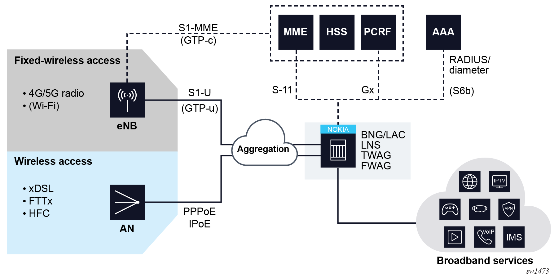
In addition to wireline subscribers, Nokia BNG also supports subscriber management for wireless users:
- subscribers connected to cellular network (4G, 5G radio) are stationary subscribers (wireless home gateways), part of Fixed Wireless Access
- wireless subscribers connected to the network via trusted wireless LAN where mobility between the Wi-Fi access points is supported.
These subscribers should not be confused with Wi-Fi devices behind the wireline subscribers, such as residential gateways.
Over the years, the BNG has evolved from copper and fiber-based wireline access to a versatile multi-access gateway (MAG) that can aggregate a wide range of wireline and wireless access technologies.
Market demands for scalability and cost reduction necessitated further architectural changes where the BNG control plane has been moved into the cloud. For more information about such disaggregated BNG, see "BBF TR-459: Control and User Plane Separation for a disaggregated BNG" in the https://www.broadband-forum.org/technical-reports.
Network design considerations – from customer premise to the central office
Network design, particularly from a customer premise to the central office, entails many key considerations to ensure reliable, efficient, and adaptable services. These considerations encompass network architecture, customer premises equipment, access methods, potential aggregation network, and the BNG design and location.
There are several additional considerations that could help to ensure the network is robust, efficient, and prepared for future needs, including the following:
-
network scalability
Design the network to allow for easy scaling. As the number of users or the demand for data grows, you should be able to add capacity without major redesigns or disruption.
-
service quality
Different customers and applications may have different Quality of Service (QoS) requirements. Your network design should allow for QoS differentiation and guarantees.
-
security considerations
Protecting the network from malicious activities is crucial. This might include strategies for preventing, detecting, and responding to attacks.
-
network automation and orchestration
As networks grow more complex, automation becomes more important. This can include automated provisioning, configuration, and fault management.
-
multiservice support
The network should be capable of supporting multiple services (voice, data, video, and so on) and types of traffic (unicast, multicast, broadcast, and so on).
-
power requirements
For hardware installed at customer premises or in the field, consider the power requirements and availability.
-
operational costs
Consider the operational costs such as maintenance, power, cooling, and network management. These factors could impact the total cost of ownership.
-
vendor interoperability
Make sure that the equipment from different vendors can work together without compatibility issues.
-
regulatory and legal compliance
Depending on the jurisdiction, there might be legal requirements to consider, such as privacy regulations.
-
emerging technologies
Be aware of emerging technologies and industry trends, such as 5G, IoT, edge computing, and so on. A forward-thinking network design can better adapt to these technologies when they become more prevalent.
-
current and future needs
A network design project should start with a clear understanding of the current requirements and future needs, and then consider these and other factors to create a network that is resilient, efficient, and adaptable.
Centralized versus distributed architecture
A fundamental consideration is whether to implement a centralized or distributed network architecture. Centralized models pool resources into a single location, simplifying management but potentially create a single point of failure. On the other hand, distributed networks decentralize resources, enhancing resiliency, but at the cost of increased management complexity. Geographical redundancy (geo-red) is another significant consideration, allowing service continuity even if a specific geographical area experiences a failure.
Customer premise
The customer premise may include a variety of devices, including routed and bridged Residential Gateways (RGs), that may employ Network Address Translation (NAT). Understanding the needs of different customer types (residential or business) further impacts network design, as some types of customers might require more advanced features or higher service levels. Virtual Residential Gateway (vRGW), service per Virtual Local Area Network (VLAN), subscriber per VLAN models, or even a flat (untagged) network might be used depending on the specific requirements.
Deciding on a service per VLAN, subscriber per VLAN, or flat network model can significantly impact the network design, scalability, and management. Each model can be influenced by the following network factors:
-
service per VLAN
This model associates different services with distinct VLANs. For example, Internet access, VoIP, and IPTV could each be on a separate VLAN. This design allows for easier QoS management, as different services typically have different QoS requirements.
-
subscriber per VLAN
Each subscriber is assigned to their unique VLAN. This model can provide high granularity for managing services and security since traffic from each subscriber is isolated from the others. However, this model significantly increases the number of VLANs.
-
flat network (single VLAN or untagged)
In this model, all subscribers share a single VLAN or operate in an untagged network. This simplifies the network design and management because you do not have to manage multiple VLANs. However, it offers less granularity for service and security management, and it can create larger broadcast domains, which might impact performance.
When deciding between these models, consider the following factors:
-
scalability
How many subscribers or services does the network need to support, now and in the future?
-
service differentiation
Will you need to provide different QoS levels for different services or subscribers?
-
security
How important is it to isolate traffic from different subscribers or services?
-
management complexity
How equipped are you to manage a potentially large number of VLANs?
-
performance
How does the chosen model impact network performance?
Access
Network access methods can be wired, wireless, or hybrid access solutions that mix fixed and wireless access.
Physical access technologies include the following:
-
fiber optics
This includes Fiber to the Home (FTTH), Fiber to the Building (FTTB), Fiber to the Curb (FTTC), and Fiber to the Node (FTTN). Fiber optics offer high bandwidth, low latency, and resistance to electromagnetic interference.
-
twisted pair
This includes Digital Subscriber Line (DSL) technologies such as ADSL, VDSL, and G.fast. These technologies deliver broadband over the existing telephone lines.
-
coaxial cable
Cable broadband services, such as DOCSIS, use coaxial cables originally installed for cable TV.
-
wireless
Wireless broadband can include Wi-Fi, cellular (4G, 5G), satellite, and fixed wireless access.
-
satellite
Satellite broadband can reach areas where terrestrial broadband is not available.
Logical access protocols include:
-
Asynchronous Transfer Mode (ATM)
This is often used for DSL connections, but it is less common today because of its lower efficiency for packet data.
-
Ethernet
This is commonly used for FTTP and cable services, and for DSL services that use Ethernet over DSL (EoDSL).
-
Passive Optical Network (PON)
This is a type of fiber network that uses passive splitters to deliver broadband to multiple premises. Variants include GPON and EPON.
-
Data Over Cable Service Interface Specification (DOCSIS)
This is used for delivering broadband over coaxial cable networks.
-
G.fast
This is a DSL protocol designed for short distances with high speeds, often used for FTTC or FTTdp (Fiber to the Distribution Point).
-
Point-to-Point Protocol over Ethernet/ATM (PPPoE/PPPoA)
These are tunneling protocols often used with DSL services.
The choice of access technology and protocol depends on factors such as the existing infrastructure, required bandwidth, service area characteristics, and cost. For example, FTTH with GPON may be the best choice for a new installation in a densely populated area, while VDSL over existing telephone lines may be more cost-effective in an area with lower population density.
Aggregation network
The aggregation network is an optional layer that groups or aggregates multiple customer connections toward the BNG. Without an aggregation network, access nodes connect directly to the BNG. If an aggregation network is used, it could be native Ethernet or an overlay such as VPNs, Virtual Private LAN Service (VPLS), with various transport options such as Multiprotocol Label Switching (MPLS), Segment Routing over IPv6 (SRv6), or Generic Routing Encapsulation (GRE).
The decision to implement an aggregation network or directly connect access nodes to BNGs depends on several factors:
-
scale
In a large network with numerous access nodes, an aggregation network can simplify management by reducing the number of direct connections to the BNG. Each BNG can connect to several aggregation switches, which in turn connect to multiple access nodes. However, for a small network, direct connections from the access nodes to the BNG may be simpler and more cost-effective.
-
geographical distribution
If access nodes are widely dispersed, it may be more efficient to connect them to a local aggregation switch and then connect the aggregation switches to a centralized BNG. This can reduce long-haul links and save costs.
-
redundancy and resilience
An aggregation network can provide additional paths between the access nodes and the BNG, enhancing network resilience. If a direct link to the BNG fails, traffic can be rerouted through another aggregation switch.
-
service management
Aggregation networks can also offer service-specific features. For instance, they may support Multiprotocol Label Switching (MPLS) for traffic engineering or Virtual Private LAN Service (VPLS) for Layer 2 VPNs.
-
cost
Aggregation networks require additional equipment and potentially more complex management, which can increase costs. However, they can also reduce the number of required BNG ports, which may offset some of these costs.
-
future-proofing
An aggregation network can offer more flexibility to accommodate future growth or changes. For example, it can be easier to add, remove, or relocate access nodes without disturbing the BNG.
Subscriber termination
Subscriber terminations occur on the BNG, usually located in the central office. The design could be centralized or distributed. Centralized BNGs host a large number of subscribers, making redundancy critical to prevent service disruption. Distributed BNGs could provide better scalability and resiliency, but may require more sophisticated management and orchestration.
Resiliency
Resilience and redundancy are critical aspects of any network design strategy. How and where to implement redundancy depends on several factors, including the expected reliability, the cost of downtime, and the available budget. Here are some redundancy strategies:
-
redundancy at the customer premise level
This scenario involves setting up dual connections from the Customer Premises Equipment (CPE) to the network. These connections may be to the same network device (such as a dual-homed connection to a single access node) or to two different devices (a multihomed connection). The advantage here is that a single failed connection does not disrupt the service of the customer. However, the cost is higher as it requires more equipment.
-
redundancy at the access node level
In this scenario, each access node could have redundant connections to the BNG or to the aggregation network. This can provide a higher level of redundancy as it protects against both a connection failure and an access node failure. However, it requires more network resources (more connections and potentially more BNG ports) and it increases complexity, which could impact network performance or troubleshooting.
-
redundancy in the aggregation network or the BNG
This scenario could involve redundant connections, redundant devices, or both. For example, the aggregation network could have a redundant path to each BNG, and each BNG could have a redundant connection to the core network. Moreover, for a highly critical BNG, there could be a backup BNG that can take over if the primary BNG fails.
In all cases, network designers must balance the cost and complexity of redundancy against the cost and impact of potential downtime. Redundancy can significantly improve network reliability, but it comes with increased cost and complexity. Therefore, it is essential to understand the business needs and expectations before deciding where and how to implement redundancy.
Subscriber management in routed central office
Subscriber management in the routed central office (RCO) model, shown in RCO, represents one of the most widely adopted approaches, that offers support for various device types such as IPoEv4/v6 and PPPoEv4/v6. In this model, subscribers are typically terminated on the BNG located within a local central office. The use of an aggregation network in this setup is optional; access nodes can be directly connected to the BNG without an aggregation network or connected via such a network.
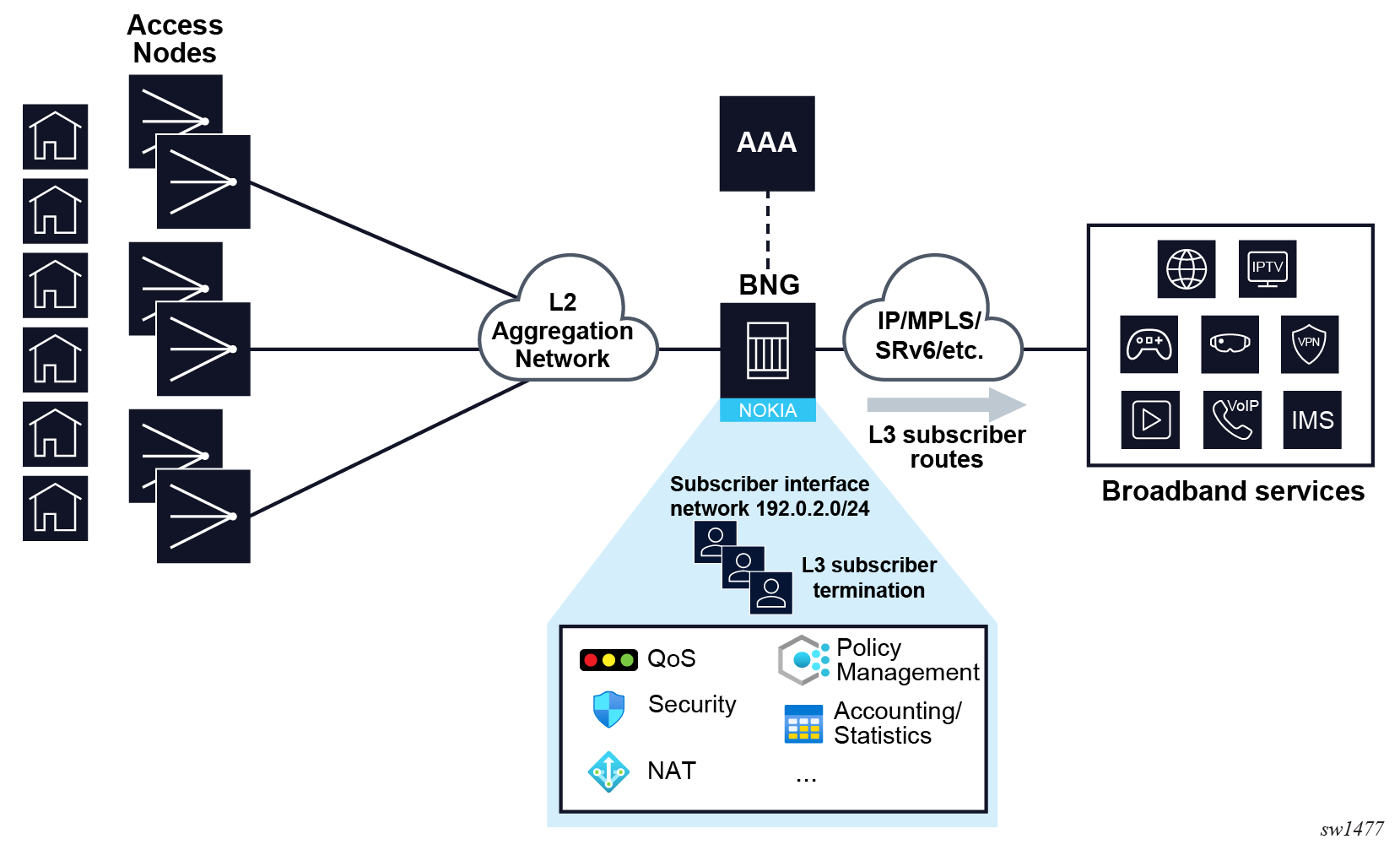
In RCO models, subscribers are terminated on Layer 3 interfaces. In SR OS, a conventional Layer 3 service interface is associated with a single SAP representing a single VLAN or VLAN pair. To accommodate multiple SAPs, that is multiple VLANs or VLAN pairs, under a single interface, two new interface types are introduced: subscriber and group interfaces. While subscriber interfaces define subscriber IP subnets, group interfaces play a pivotal role in aggregating SAPs. For a detailed explanation of group and subscriber interfaces and their respective roles, see Subscriber interface and Group interface.
Within each IES or VPRN service, users have the flexibility to create multiple subscriber interfaces, each of which must include at least one subnet. The distribution of these subscriber subnets into routing protocols is determined by user-defined import or export route policies.
Group interfaces are provisioned within the subscriber interface and share the associated subscriber subnets. These group interfaces can represent either a collection of subscribers on an Access Node (AN) or the AN itself.
Static SAPs are configured under the group interface. Managed (or dynamic) SAPs are automatically created under the group interfaces. For more information, see Managed SAP and Capture SAP. For example, in a VLAN-per-AN model, only one SAP per group interface is required. In contrast, in a VLAN-per-subscriber model, each subscriber on the AN necessitates its own SAP. All SAPs on a group interface must be on the same physical port or Link Aggregation Group (LAG).
For more information about static SAPs see the SAPs section in the 7450 ESS, 7750 SR, 7950 XRS, and VSR Services Overview Guide.
Various subscriber-related features, including DHCP relay, DHCP snooping, PPPoE parameters, IPv6 parameters, anti-spoofing filters, and more, are enabled at the group interface level.
Because the RCO model serves as the primary deployment model, all examples provided in this guide are contextualized within the RCO model.
Subscriber management in distributed network edge
For more information, see Appendix: Subscriber management in distributed access aggregation devices.
Subscriber management concepts
There are several Nokia BNG concepts that need introduction to better understand subscriber management. The following section defines those concepts and the CLI configuration details.
Subscriber
A broadband subscriber represents a residential or a small business user. At a nodal level, a subscriber is typically defined by a unique subscriber identifier to which an assortment of policies (or subscriber profiles) can be applied. This uniquely identifies a billable entity for the service provider.
In Nokia BNG, a subscriber is identified by a subscriber identification string (subscriber-id) of maximum 64 characters long. This subscriber ID can then be passed to the external systems where management, troubleshooting, and billing operations require the subscriber ID name. In Nokia BNG, the subscriber ID can be assigned by several means:
- Use RADIUS, DIAMETER, or a Local User Database (LUDB), which are commonly referred to as authentication sources, during the authentication phase to assign the subscriber ID.
- Use a Python script during the instantiation process of the subscriber.
- Configure explicit defaults on a SAP level, which take effect if the subscriber ID
is not provided by the previous two methods. On the SAP level,
subscriber-id can be:
- provisioned statically as a string
- mapped to a SAP-id
- automatically derived as a concatenation of user-defined subscriber identification
- Implicit default is enabled on the system level and it takes effect if none of the preceding methods are enabled. The subscriber-id is a 10-character string consisting of the characters A-Z and 0-9 autogenerated based on the subscriber identification fields.
Although the subscriber ID can be configured in multiple places, the value that takes effect in the system is selected from a single source that is determined in the order of priority. For more information about prioritization of authentication sources, see Prioritization of authentication sources.
RADIUS returned subscriber ID
The subscriber ID can be obtained from RADIUS during the authentication phase. The name of the Nokia-specific RADIUS attribute for subscriber ID is Alc-Subsc-ID-Str.
For more information about this attribute, see the 7450 ESS, 7750 SR, and VSR RADIUS Attributes Reference Guide.
NASREQ returned subscriber ID
The subscriber ID can be obtained from DIAMETER NASREQ in an AA-Answer message during the authentication phase. The name of the Nokia-specific AVP for subscriber ID is Alc-Subsc-ID-Str.
For more information about this AVP, see Diameter NASREQ application.
DIAMETER Gx returned subscriber ID
The subscriber ID can be obtained from DIAMETER Gx in a CC-Answer message during the authentication phase. Include the predefined string “Sub-Id:<sub-id-string>” in the Charging-Rule-Install / Charging-Rule-Name AVP.
For more information about this AVP, see the 7750 SR and VSR Gx AVPs Reference Guide and Policy management via Gx interface.
LUDB returned subscriber ID
The subscriber ID can be obtained from LUDB during the authentication phase. Use the following commands to configure the subscriber ID:
- MD-CLI
configure subscriber-mgmt local-user-db ipoe host identification subscriber-id configure subscriber-mgmt local-user-db ppp host identification subscriber-id - classic
CLI
configure subscriber-mgmt local-user-db ipoe host identification-strings subscriber-id
configure subscriber-mgmt local-user-db ppp host identification-strings subscriber-id
For more information about LUDB see LUDB only access and "Local User Database for the Enhanced Subscriber Management" section in 7450 ESS, 7750 SR, and 7950 XRS Advanced Configuration Guide Part III
Python returned subscriber ID for DHCP based hosts
A DHCP-based host can be assigned a subscriber ID from a Python script configured in Nokia BNG. This can be triggered by the DHCP messages and using Nokia provided Python APIs.
For more information about Python, see Python script support for ESM and LUDB access by DHCPv4 server.
Defaults for subscriber ID
Explicit defaults for subscriber ID are configured under the SAP or MSAP policy and can be configured as:
- a static configured string
- the SAP identifier
- a concatenation of user-defined subscriber identification fields obtained during session initiation, such as SAP ID, MAC, circuit-ID, remote-id, and PPPoE session ID
Implicit defaults for subscriber ID are configured at the node level and generates 10-character encoded string as the subscriber ID. It takes effect if no other method to obtain the subscriber ID is available.
For more information about auto generated defaults for subscriber IDs, see Auto-sub ID.
Static subscriber ID
Static subscriber ID is configured as a custom string under the sap or msap-policy context and takes effect if the subscriber ID is not returned through authentication sources (RADIUS, Diameter or LUDB) or through a Python script.
Assigning a static subscriber ID makes more sense for static SAP where each SAP corresponds to a subscriber, as shown in the following example.
Static subscriber ID (MD-CLI)
[ex:/configure service vprn "demo-vprn" subscriber-interface "demo-sub-if" group-interface "demo-grp-if"]
A:admin@node-2# info
    sap 1/x1/1/c1/1:1.1 {
        sub-sla-mgmt {
            defaults {
                subscriber-id {
                    string "user-1"
                }
            }
        }
    }
Static subscriber ID (classic CLI)
A:node-2>config>service>vprn>sub-if>gpp-if# info
----------------------------------------------
sap 1/x1/1/c1/1:1.1 create
    sub-sla-mgmt
        def-sub-id string "user-1"
    exit
exit
----------------------------------------------
In a deployment model where SAP is created dynamically via the subscriber initiation control packets (for example, DHCP, PPPoE, ARP, or even a data trigger), the static subscriber ID is configured in the msap-policy context, as shown in the following example.
Static subscriber ID for dynamically created MSAPs (MD-CLI)
[ex:/configure subscriber-mgmt]
A:admin@node-2# info
    msap-policy "demo-msap" {
        sub-sla-mgmt {
            defaults {
                subscriber-id {
                    string "user-1"
                }
            }
        }
    }
Static subscriber ID for dynamically created MSAPs (classic CLI)
A:node-2>config>subscr-mgmt# info
----------------------------------------------
        msap-policy "demo-msap" create
            sub-sla-mgmt
                def-sub-id string "user-1"
            exit
        exit
----------------------------------------------
In this case, there is only one subscriber ID for all SAPs sharing this msap-policy.
For more information about dynamic SAP instantiation, see Managed SAP and Capture SAP.
SAP ID as subscriber ID
A subscriber ID can be mapped to a SAP ID. Similar to static subscriber ID assignment, this is configured under a sap or msap-policy context and it takes effect if the subscriber ID is not returned through authentication sources (RADIUS, Diameter or LUDB) or through a Python script.
In the following example a subscriber ID becomes (1/x1/1/c1/1:1.1).
SAP ID as subscriber ID (MD-CLI)
[ex:/configure service vprn "demo-vprn" subscriber-interface "demo-sub-if" group-interface "demo-grp-if"]
A:admin@node-2 # info
    sap 1/x1/1/c1/1:1.1 {
        sub-sla-mgmt {
            defaults {
                subscriber-id {
                    sap-id
                }
            }
        }
    }
SAP ID as subscriber ID (classic CLI)
A:node-2>config>service>vprn>sub-if>gpp-if# info
----------------------------------------------
sap 1/x1/1/c1/1:1.1 create
    sub-sla-mgmt
        def-sub-id use-sap-id
    exit
exit
----------------------------------------------
For dynamically created SAPs, the subscriber ID is mapped to the SAP ID at the time of the SAP creation.
SAP ID as subscriber ID for dynamically created MSAPs (MD-CLI)
[ex:/configure subscriber-mgmt]
A:admin@node-2# info
    msap-policy "demo-msap" {
        sub-sla-mgmt {
            defaults {
                subscriber-id {
                    sap-id
                }
            }
        }
    }
SAP ID as subscriber ID for dynamically created MSAPs (classic CLI)
A:node-2>config>subscr-mgmt# info
----------------------------------------------
        msap-policy "demo-msap" create
            sub-sla-mgmt
                def-sub-id use-sap-id
            exit
        exit
----------------------------------------------
For more information about dynamic SAP instantiation, see Managed SAP and Capture SAP.
Autogenerated subscriber ID
The autogenerated format of the subscriber ID name can be a user-friendly string based on the subscriber identification fields that are dependent on the session type (DHCP or PPPoE).
Examples of the host or session identification fields that are common to DHCP and PPPoE include:
- MAC address
- SAP ID
- circuit ID
- remote ID
For the complete list of command options for the configure subscriber-mgmt auto-sub-id command, see the following:
-
7450 ESS, 7750 SR, 7950 XRS, and VSR Classic CLI Command Reference Guide
-
7450 ESS, 7750 SR, 7950 XRS, and VSR MD-CLI Command Reference Guide
The automatic subscriber ID is generated at the end of the host or session initiation process (after the authentication phase is completed) and only in the case when the subscriber ID has not been already provided by any other more specific means (RADIUS, Diameter, LUDB, or Python).
Similar to the previous two cases, the explicit auto subscriber ID generation is enabled as follows:
- MD-CLI
configure service vprn subscriber-interface group-interface sap sub-sla-mgmt defaults subscriber-id auto-id configure service ies subscriber-interface group-interface sap sub-sla-mgmt defaults subscriber-id auto-id - classic
CLI
configure service ies subscriber-interface group-interface sap sub-sla-mgmt def-sub-id use-auto-id
configure service vprn subscriber-interface group-interface sap sub-sla-mgmt def-sub-id use-auto-id
The subscriber host or session identification fields used in automatic generation of the subscriber ID are configured on a nodal level, which means that there can be only a single set of subscriber identification fields defined per host or session type (IPoE or PPPoE) per BNG.
Auto subscriber ID identification fields can be reconfigured only if no active sessions using this method of assignment of the subscriber ID are present in the system. Auto-sub-id is not applicable to static subscribers.
Subscriber Session
A subscriber session in the BNG represents a user device to which the subscriber management functions are applied. This device can be a single stack device (IPv4 or IPv6) or dual-stack device (IPv4 or IPv6 with various combinations of IPv6 addresses, SLAAC, DHCP-IA-NA, DHCP-IA-PD).
A subscriber session can be either statically configured or dynamically learned in the BNG based on trigger packets. Trigger packets are typically DHCP and PPPoE control packets starting with DHCPv4 Discover, DHCPv6 Solicit, or PPPoE Active Discovery Initiation (PADI) messages. However, they can also be as simple as an ARP packet, IPv6 Router Solicitation, or even a generic IP data packet.
The subscriber sessions are instantiated on a SAP and are uniquely identified by various fields such as MAC address, IP address, circuit ID, remote ID, and others. Subscriber sessions of the same subscriber can be instantiated on a single SAP or spread across multiple SAPs on the same port.
During the subscriber session instantiation process, resources such as queues, filters, and counters are associated with the session. Although the queues, filters, and counters are not the only resource allocated with the session, they are the primary ones through which various policies are applied.
A subscriber can have a single or multiple sessions instantiated, depending on the configuration of the user premise. It is expected that all sessions of a subscriber originate from the same site and are reached by the same port on the BNG. The following three figures show some of the configurations:
- Subscriber sessions in residential deployment with bridged RG shows the residential premise
with a bridged residential gateway (RG), where home devices are directly exposed to
the BNG. For example, the BNG is directly involved in their IP address assignment
through DHCP and PPPoE control packets. In this configuration, a subscriber is
associated with multiple sessions, each representing a device within a
residence.
Figure 3. Subscriber sessions in residential deployment with bridged RG 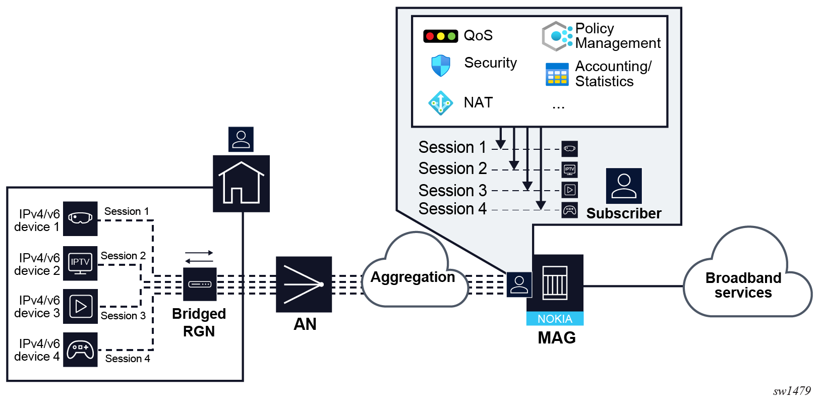
- Subscriber sessions in residential deployment with routed RG shows the residential premise
with routed RG where the residential homes are assigned the IP addresses by the RG
and in this sense their control packets never reach the BNG. The IP address of the
RG is managed by the BNG and therefore, the RG represents the subscriber session. In
this configuration, a subscriber has a single session that represents the RG itself.
The RG may or may not run a NAT that hides the IP addresses of devices in the
residence.
Figure 4. Subscriber sessions in residential deployment with routed RG 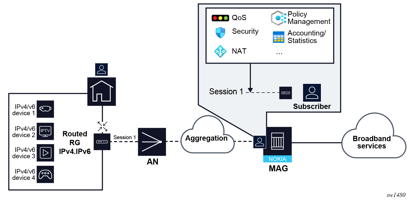
- Subscriber sessions in small business deployments with routed CPE shows the small business
deployment with routed CPE. This scenario is similar to the previous one, where the
service offered to the subscribers are different.
Figure 5. Subscriber sessions in small business deployments with routed CPE 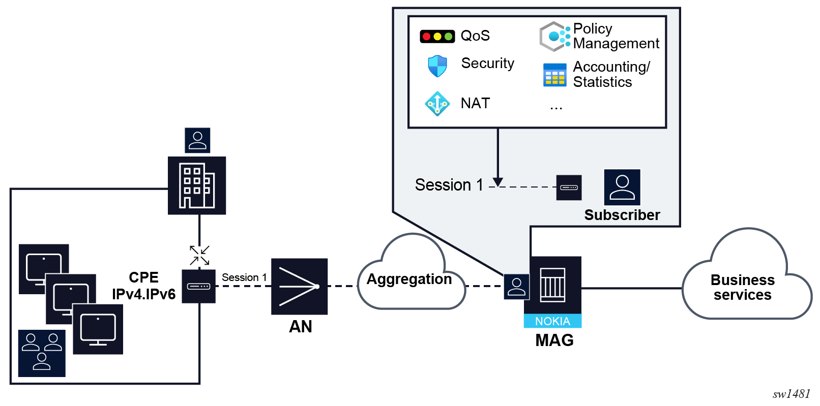
Service Level Agreement profile
The Service Level Agreement (SLA) profile contains QoS, security and other settings that are applicable to one, a subset, or all session in a home. An SLA profile is a template that can be shared by many subscriber sessions. Some of the settings in the SLA profile include:
-
egress and ingress QoS configuration
-
egress scheduler policy HQoS
-
egress and ingress IP filters
-
session limits
-
idle timeout for the sessions
-
statistics collection
-
credit control parameters
The SLA profile becomes instantiated when the resources defined in the template are allocated, at which point the SLA profile becomes an SLA profile instance (SPI). By default, SPIs are created during the session setup process for every unique combination of:
- SLA profile name
- SAP
- Subscriber-ID
If the SLA profile does not explicitly define an ingress or egress QoS policy or filters, the default SAP ingress or default SAP egress QoS policy or filter is used.
Use the commands in the following context to configure SLA profile.
configure subscriber-mgmt sla-profileFor the complete list of command options for the configure subscriber-mgmt sla-profile command, see the following:
-
7450 ESS, 7750 SR, 7950 XRS, and VSR Classic CLI Command Reference Guide
-
7450 ESS, 7750 SR, 7950 XRS, and VSR MD-CLI Command Reference Guide
The following example shows the SLA profile called “demo”. The commands presented in this example are only a subset of a larger set of commands under the SLA profile.
MD-CLI
[ex:/configure subscriber-mgmt sla-profile "demo"]
A:admin@node-2# info
    credit-control-policy "demo-cc-policy"
    egress {
        ip-filter "demo-filter-egress"
        qos {
            sap-egress {
                policy-name "demo-qos"
            }
        }
    }
    session-limits {
        ipoe 8
        overall 10
        pppoe {
            local 8
        }
    }
    ingress {
        ip-filter "demo-filter-ingress"
    }
classic CLI
A:node-2>config>subscr-mgmt>sla-prof# info
----------------------------------------------
            credit-control-policy "demo-cc-policy"
            session-limits
                ipoe 8
                pppoe-local 8
                overall 10
            exit
            ingress
                ip-filter 11
            exit
            egress
                qos 20
                exit
                ip-filter 10
            exit
----------------------------------------------
Subscriber profile
The subscriber profile is a template that contains the applicable settings for all sessions that belong to the same subscriber. Examples include:
- ingress and egress QoS scheduler policy and policer control policy
- egress aggregate rate limit
- RADIUS accounting policy
- IGMP policy
- MLD policy
- PIM policy
- session limits
Subscribers are either explicitly mapped to a subscriber profile template or are dynamically associated with a subscriber profile.
Attempting to delete any subscriber profile (including the profile named "default") while in use by an existing active subscriber, fails.
Use the commands in the following context to configure a subscriber profile.
configure subscriber-mgmt sub-profileFor the complete list of command options for the configure subscriber-mgmt sub-profile command, see the following:
-
7450 ESS, 7750 SR, 7950 XRS, and VSR Classic CLI Command Reference Guide
-
7450 ESS, 7750 SR, 7950 XRS, and VSR MD-CLI Command Reference Guide
The following example shows the subscriber profile called “demo”. A subscriber using this profile has an egress aggregate rate limit of 100Mbps, is using RADIUS accounting policy “acct-1”, and has a limit of 10 IPoE sessions. The commands presented in this example are only a subset of a larger set of commands under the subscriber profile.
MD-CLI
[ex:/configure subscriber-mgmt sub-profile "demo"]
A:admin@node-2# info
    egress {
        qos {
            agg-rate {
                rate 100000
            }
        }
    }
    radius-accounting {
        policy ["acct-1"]
    }
    session-limits {
        ipoe 10
    }
classic CLI
A:node-2>config>subscr-mgmt>sub-prof# info
----------------------------------------------
            session-limits
                ipoe 10
            exit
            radius-accounting
                policy "acct-1"
            exit
            egress
                agg-rate-limit 100000
            exit
----------------------------------------------
Subscriber identification policy
A subscriber identification policy is used by dynamically created sessions and it contains:
- URL pointers to the Python scripts used for dynamic session identification based on the information present in the DHCPv4 ACK message. These scripts represent a legacy method for dynamic DHCP session identification. For more information on Python scripting in ESM on the BNG , see Python script support for ESM.
- A subscriber profile map and an SLA profile map. The subscriber profile map creates a mapping between the sub and SLA profile strings returned by the Python script, LUDB, RADIUS or NASREQ and the profile names configured in the BNG. See SLA and subscriber profile mapping.
- DHCP options from which the subscriber identification strings can be derived. Some deployments require that DHCPv4 server provides subscriber strings necessary for subscriber identification.
A subscriber identification policy is defined using the following command:
- MD-CLI
configure subscriber-mgmt sub-ident-policy name "sub-ident-policy-1" - classic
CLI
configure subscriber-mgmt sub-ident-policy "sub-ident-policy-1"
SLA and subscriber profile mapping
In the BNG, the following elements must be assigned to a subscriber during the instantiation phase:
- subscriber identification string (subscriber ID). The subscriber ID can be assigned statically via configuration, or obtained via authentication sources, where it can be derived based on various other parameters obtained during the session instantiation phase. For more information, see Subscriber.
- SLA profile
- subscriber (SUB) profile
- IP address
Both, the SLA and SUB profiles are statically configured in the BNG, but their association to subscribers can be flexible.
Static sessions setup under SAPs link directly to the SLA and SUB profiles using their designated names.
In contrast, dynamic sessions use SLA and SUB profile strings retrieved from authentication sources. These strings are subsequently mapped, or translated, to their corresponding SLA and SUB profile names configured in the BNG. This mapping process is configured in the subscriber identification policy.
In many deployments, the SLA and SUB profile strings and their respective SLA and SUB profile names are identical and a default direct mapping can be configured.
RADIUS returns the SLA-profile string for the session:
Alc-SLA-Prof-Str = "demo-1"The following example shows the actual SLA profile as defined in the BNG.
MD-CLI
[ex:/configure subscriber-mgmt]
A:admin@node-2# info
    sla-profile "sla-profile-1" {
        egress {
            qos {
                sap-egress {
                    policy-name "demo-qos-policy-1"
                }
            }
        }
        ingress {
            ip-filter "demo-filter-1"
        }
    }
classic CLI
A:node-2>config>subscr-mgmt# info
----------------------------------------------
        sla-profile "sla-profile-1" create
            ingress
                ip-filter 40
            exit
            egress
                qos 10
                exit
            exit
        exit
----------------------------------------------
The mapping between the SLA profile string and the SLA profile name (as defined in the BNG) is defined in the subscriber identification policy.
MD-CLI
[ex:/configure subscriber-mgmt sub-ident-policy "test"]
A:admin@node-2# info
    sla-profile-map {
        entry "demo-1" {
            sla-profile "sla-profile-1"
        }
    }
classic CLI
A:node-2>config>subscr-mgmt>sub-ident-pol# info
----------------------------------------------
            sla-profile-map
                entry key "demo-1" sla-profile "sla-profile-1"
            exit
----------------------------------------------
The sub-ident-policy is referenced under the SAP (or msap-policy) on which the session is instantiated. In this case, a session for which the SLA profile string ‘demo-1’ is returned via RADIUS is associated with the SLA profile “sla-profile-1”.
In case that translation is not required, the following CLI can be used.
MD-CLI
[ex:/configure subscriber-mgmt sub-ident-policy "test"]
A:admin@node-2# info
    sla-profile-map {
        use-direct-map-as-default true
    }
    sub-profile-map {
        use-direct-map-as-default true
    }
classic CLI
A:node-2>config>subscr-mgmt>sub-ident-pol# info
----------------------------------------------
            sub-profile-map
                use-direct-map-as-default
            exit
            sla-profile-map
                use-direct-map-as-default
                entry key "demo-1" sla-profile "sla-profile-1"
            exit
----------------------------------------------
Subscriber interface
A subscriber interface is a special type of interface under which subscriber sessions are instantiated. This is an internal loopback interface that supports multiple IP subnets that can be shared across many access nodes on different ports within the BNG. Those subnets aggregating subscribers are advertised via routing protocols on the network side for downstream reachability. Optionally, this interface can be unnumbered, in which case each subscriber session is advertised individually into the network. A subscriber interface contains IP addressing configuration as well as session-specific configurations.
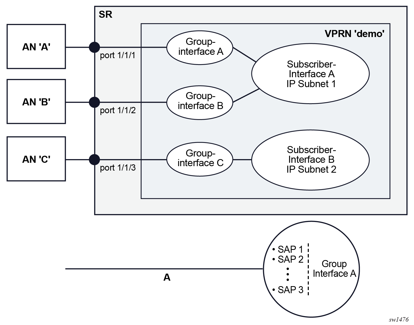
Group interface
Group interfaces are configured under the subscriber interfaces and they allow multiple SAPs on the same port to be part of the same interface. This is in contrast to traditional interfaces where each interface is associated with a single SAP. This aggregation of SAPs is also relevant in multichassis redundancy where states of the SAPs can be communicated between the nodes on an aggregate level instead of on an individual SAP level. The group interface is an unnumbered interface. The interface is operationally up if it is administratively enabled and if at least one SAP has been defined and is up and the parent subscriber interface is administratively up. The first SAP defined determines the port for the group interface. If the user attempts to define a subsequent SAP that is on a different port, it results in an error. When the subscriber interface or the group interface is administratively disabled, no packets are delivered or received to or from the subscriber session. However, the subscriber sessions, both dynamic and static, are maintained as long as the lease times are still valid.
Multiple group interfaces under the same subscriber interface share the same IP subnets. Each group interface can accommodate subscribers from a single port on the BNG, whether it is a faceplate, LAG, or a PW-port. The first SAP associated with the group interface determines the port for the group interface.
The concept of subscriber and group interface is shown in the figure that follows.
The following is a sample configuration of the subscriber interface and a single group interface under it (although multiple group-interfaces can be configured). No SAPs are configured because they are automatically assigned through capture SAP configuration. With the oper-up-while-empty configuration command, the group-interface is operationally up with no SAPs assigned. For more information about configuring a capture SAP, see Managed SAP and Capture SAP. This configuration supports IPv4 and IPv6 DHCP and PPPoE configuration with IP subnets shown in the following example.
MD-CLI
[ex:/configure service vprn "esm" subscriber-interface "sub-int-1"]
A:admin@node-2# info
    admin-state enable
    ipv4 {
        address 10.10.0.254 {
            prefix-length 24
        }
        address 10.10.1.254 {
            prefix-length 24
        }
    }
    ipv6 {
        delegated-prefix-length variable
        prefix 2001:db8:bbbb::/56 {
            host-type wan
        }
        prefix 2001:db8:bbbb:100::/56 {
            host-type pd
        }
    }
    group-interface "group-int-1" {
        admin-state enable
        oper-up-while-empty true
        ipv4 {
            dhcp {
                admin-state enable
                server [192.168.0.1]
                trusted true
                gi-address 10.10.0.254
                match-circuit-id true
                option-82 {
                    action keep
                    vendor-specific-option {
                        pool-name true
                    }
                }
                lease-populate {
                    max-leases 100
                }
                client-applications {
                    dhcp true
                }
            }
        }
        ipv6 {
            auto-reply {
                neighbor-solicitation true
                router-solicitation true
            }
            dhcp6 {
                pd-managed-route {
                }
                relay {
                    admin-state enable
                    server ["2001:db8::1"]
                    client-applications {
                        dhcp true
                        ppp true
                    }
                }
            }
            router-advertisements {
                admin-state enable
                force-mcast ip-mac
                options {
                    managed-configuration true
                    reachable-time 10000
                    retransmit-timer 3
                }
            }
            router-solicit {
                admin-state disable
            }
        }
        ipoe-session {
            admin-state enable
            ipoe-session-policy "ipoe-session-policy-1"
            user-db "demo-1"
            sap-session-limit 100
        }
        pppoe {
            admin-state enable
            policy "ppp-policy-1"
            session-limit 100
            sap-session-limit 100
            user-db "demo-1"
        }
        local-address-assignment {
            admin-state enable
            ipv4 {
                server "dhcpv4"
                client-applications {
                    ppp true
                }
            }
        }
    }
classic CLI
A:node-2# configure service vprn "esm" subscriber-interface "sub-int-1"
A:node-2>config>service>vprn>sub-if# info
----------------------------------------------
                address 10.10.0.254/24
                address 10.10.1.254/24
                ipv6
                    delegated-prefix-len variable
                    subscriber-prefixes
                        prefix 2001:db8:bbbb::/56 wan-host
                        prefix 2001:db8:bbbb:100::/56 pd
                    exit
                exit
                group-interface "group-int-1" create
                    ipv6
                        auto-reply
                            neighbor-solicitation
                            router-solicitation
                        exit
                        router-advertisements
                            force-mcast ip mac
                            managed-configuration
                            reachable-time 10000
                            retransmit-time 3
                            no shutdown
                        exit
                        dhcp6
                            pd-managed-route next-hop ipv6
                            relay
                                server 2001:db8::1
                                client-applications dhcp ppp
                                no shutdown
                            exit
                        exit
                    exit
                    local-address-assignment
                        server "dhcpv4"
                        client-application ppp-v4
                        no shutdown
                    exit
                    dhcp
                        option
                            action keep
                            circuit-id
                            no remote-id
                            vendor-specific-option
                                pool-name
                            exit
                        exit
                        server 192.168.0.1
                        trusted
                        lease-populate 100
                        gi-address 10.10.0.254
                        match-circuit-id
                        no shutdown
                    exit
                    ipoe-session
                        ipoe-session-policy "ipoe-session-policy-1"
                        sap-session-limit 100
                        user-db "demo-1"
                        no shutdown
                    exit
                    oper-up-while-empty
                    pppoe
                        policy "ppp-policy-1"
                        session-limit 100
                        sap-session-limit 100
                        user-db "demo-1"
                        no shutdown
                    exit
                exit
----------------------------------------------
Managed SAP and Capture SAP
Subscriber sessions are created on a subscriber SAP. For a shared VLAN deployment model, these SAPs are usually statically configured as the limited number of VLANs are known. For a VLAN per-subscriber deployment model, it is advantageous that the subscriber SAPs are automatically created and deleted when subscriber sessions connect or disconnect. These are called Managed SAPs (MSAPs).
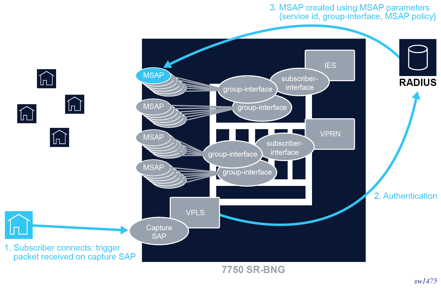
A capture SAP is a SAP on which new subscriber sessions on unconfigured VLANs are discovered. It actively monitors all session initiation traffic (trigger packet) on an underlying port, for example, PADI or DHCP traffic. If this incoming traffic does not correspond to an existing managed SAP, the capture SAP forwards this traffic to the CPM. Assuming the session is legitimate, the CPM extracts the VLANs for the ensuing session.
The reception of a valid trigger packet on a capture SAP initiates a RADIUS, DIAMETER, or local user database authentication to provide the service context where the MSAP should be created. The VLAN of the created MSAP is the same as the authenticated trigger packet. An MSAP functions like a regular SAP but its configuration is not user editable and not maintained in the configuration file. By default, an MSAP is deleted from the system when the last subscriber session active on the MSAP disconnects.
The following trigger types are supported on a capture SAP:
-
dhcp
DHCPv4 client messages
-
pppoe
PPPoE PADI messages from PPPoE clients
-
arp
ARP-Request from an ARP host with static configured IPv4 address
-
dhcp6
DHCPv6 client messages
-
rtr-solicit
Router Solicitation messages from a SLAAC hosts
-
data
An ARP-Request, IPv4 or IPv6 packet received from a data-triggered host
Multiple trigger types can be enabled on a single capture SAP. The data and arp trigger types are mutually exclusive.
A capture SAP is created in a VPLS service. A capture SAP does not forward traffic but captures received trigger packets for authentication. Similar to a default SAP, at least one of the Q-tags of a capture SAP must be a wildcard (*), meaning any tag value. See the following example configuration.
MD-CLI
[ex:/configure service]
A:admin@node-2# info
vpls "capture-vpls" {
        admin-state enable
        service-id 10
        customer "1"
        capture-sap 1/x1/1/c1/4:*.* {
            description "capture SAP port 1/x1/1/c1/4"
            trigger-packet {
                arp true
                dhcp true
                dhcp6 true
                pppoe true
                rtr-solicit true
            }
            msap-defaults {
                policy "msap-policy-1"
                service-name "submgmt-ies"
                group-interface "group-int-1-1"
            }
            ipoe-session {
                admin-state enable
                ipoe-session-policy "ipoe-policy-1"
                user-db "ludb-1"
            }
            pppoe {
                policy "ppp-policy-1"
                user-db "ludb-1"
            }
        }
    }
classic CLI
A:node-2>config>service# info
----------------------------------------------
vpls 10 name "capture-vpls" customer 1 create
    stp
        shutdown
    exit
    sap 1/x1/1/c1/4:*.* capture-sap create
        description "capture SAP port 1/x1/1/c1/4"
        trigger-packet arp dhcp dhcp6 pppoe rtr-solicit
        pppoe-policy "ppp-policy-1"
        pppoe-user-db "ludb-1"
        ipoe-session
            ipoe-session-policy "ipoe-policy-1"
            user-db "ludb-1"
            no shutdown
        exit
        msap-defaults
            group-interface "group-int-1-1"
            policy "msap-policy-1"
            service 1000
        exit
        no shutdown
    exit
    no shutdown
exit
----------------------------------------------
A capture SAP and default SAP cannot be configured simultaneously on a dot1q-encapsulated port. A capture SAP and default SAP cannot be configured simultaneously on a QinQ-encapsulated port when the outer tag is the same.
A SAP lookup based on the outer and inner tags is performed when a packet is received on a port. When no corresponding SAP or MSAP is found, the packet is handled by the capture SAP, meaning that the trigger packets are sent to the CPM and all other packets are dropped.
An ingress VLAN ID (VID) type mac filter can be configured on a capture SAP to have additional control on the VLANs that are allowed to initiate a host setup. Other filter types are not supported on a capture SAP.
For a capture SAP on a dot1q encapsulated port:
- port-id:*
Matches any valid single tagged trigger packet on a port-id for which no more specific SAP or MSAP is found. A single Q-tag (port-id:tag) is available for authentication. The corresponding MSAP is created as: port-id:tag
For a capture SAP on a QinQ-encapsulated port:
-
port-id:*.*
Matches any valid double tagged trigger packet on a port-id for which no more specific SAP or MSAP is found.
Both Qw-tags (port-id:tag1.tag2) are available for authentication.
The corresponding MSAP is created as: port-id:tag1.tag2.
The optional allow-dot1q-msaps command configured at the capture SAP enables additional support for single-tagged trigger packets:
- Valid single-tagged trigger packets for which no more specific SAP or MSAP is found are matched on port-id.
- A single Q-tag is available for authentication, the second tag is set to zero (port-id:tag.0).
- The corresponding MSAP is created as: port-id:tag.0.
- The following command should be configured where a combination of
port-id:tag1.0 and
port-id:tag1.tag2 MSAPs coexist. When not configured,
port-id:tag1.0 MSAPs attract double tagged
port-id:tag1.tag2 encapsulated traffic which is
either dropped (IPoE traffic) or handled as single-tagged traffic
causing PPPoE sessions to fail.
- MD-CLI
configure service system extended-default-qinq-sap-lookup - classic
CLI
configure system ethernet new-qinq-untagged-sap
Note: The SR OS R24.x.Rx Software Release Notes information indicates the platforms on which these commands are enabled by default. - MD-CLI
- port-id:tag1.*
Matches any valid double-tagged trigger packet with and outer tag equaling tag1 on port-id and for which no more specific SAP or MSAP is found.
Both -tags (port-id:tag1.tag2) are available for authentication.
The corresponding MSAP is created as: port-id:tag1.tag2.
The optional allow-dot1q-msaps command configured at the capture SAP enables additional support for single-tagged trigger packets:
- Valid single-tagged trigger packets with tag equaling tag1 and for which no more specific SAP or MSAP is found are matched on port-id.
- A single-tag is available for authentication; the second tag is set to zero (port-id:tag1.0).
- The corresponding MSAP is created as: port-id:tag1.0.
- It is a prerequisite to have the following command configured to enable
both port-id:tag1.* capture-sap and
port-id:tag1.0 MSAP to coexist. The
port-id:tag1.0 capture-sap cannot be created when
not configured.
- MD-CLI
configure service system extended-default-qinq-sap-lookup - classic
CLI
configure system ethernet new-qinq-untagged-sap
Note: The SR OS R24.x.Rx Software Release Notes information indicates the platforms on which these commands are enabled by default. - MD-CLI
- port-id:*.tag2
Both Q-tags (port-id:tag1.tag2) are available for authentication.
The corresponding MSAP is created as: port-id:tag1.tag2.
This is an inverse capture SAP that matches on a fixed inner tag with the outer tag identifying the user. The following restrictions apply when an inverse capture SAP is configured on a port:
- The only allowed port type is Ethernet.
- It is not possible to create y.* SAPs when there is a *.x capture SAP present on the port (y=0,1..4094,* and x=1..4094).
- It is not possible to create a y.* network interface when there is a *.x capture SAP present on the port (y=0,1..4094,* and x=1..4094).
- There is no support for single-tagged MSAP creation.
To enable the creation of single-tagged and double-tagged MSAPs by a QinQ-encapsulated capture SAP, enable the allow-dot1q-msap command in the capture SAP context:
- MD-CLI
configure service vpls capture-sap allow-dot1q-msaps - classic
CLI
configure service vpls sap capture-sap allow-dot1q-msaps
In addition, the following command should be configured for scenarios as previously described.
- MD-CLI
configure service system extended-default-qinq-sap-lookup - classic
CLI
configure system ethernet new-qinq-untagged-sap
Valid single-tagged trigger packets result in the creation of a port-id:tag.0 MSAP. With the encap-tag-range command option matching in a local user database, it is possible to specify different MSAP defaults for single or double-tagged MSAPs. s shown in the following example.
defaults for dot1q MSAPs (MD-CLI)
[ex:/configure subscriber-mgmt local-user-db "ludb-1"]
A:admin@node-2# info
    admin-state enable
    ipoe {
        match-list [encap-tag-range]
        host "single-tagged" {
            admin-state enable
            host-identification {
                encap-tag-range {
                    from "*.0"
                    to "*.0"
                }
            }
                        msap-defaults {
                policy "msap-policy-2"
                service-name "submgmt-vprn-2"
                group-interface {
                    name "group-int-2"
                }
            }
        }
    }
defaults for dot1q MSAPs (classic CLI)
A:node-2>config>subscr-mgmt>loc-user-db# info
----------------------------------------------
            ipoe
                match-list encap-tag-range
                host "single-tagged" create
                    host-identification
                        encap-tag-range start-tag *.0 end-tag *.0
                    exit
                    msap-defaults
                        group-interface "group-int-2"
                        policy "msap-policy-2"
                    exit
                    no shutdown
                exit
            exit
            no shutdown
----------------------------------------------
defaults for QinQ MSAPs (MD-CLI)
[ex:/configure service vpls "capture-vpls" capture-sap 1/x1/1/c1/4:*.*]
A:admin@node-2# info
    allow-dot1q-msaps true
    trigger-packet {
        dhcp true
        dhcp6 true
    }
        msap-defaults {
        policy "msap-policy-1"
        service-name "submgmt-vprn-1"
        group-interface "group-int-1"
    }
    ipoe-session {
        admin-state enable
        ipoe-session-policy "ipoe-policy-1"
        user-db "ludb-1"
    }
defaults for QinQ MSAPs (classic CLI)
A:node-2>config>service>vpls>sap# info
----------------------------------------------
    trigger-packet dhcp dhcp6
    allow-dot1q-msaps
    ipoe-session
        ipoe-session-policy "ipoe-policy-1"
        user-db "ludb-1"
        no shutdown
    exit
    msap-defaults
        group-interface "group-int-1"
        policy "msap-policy-1"
        service 2000
    exit
    no shutdown
----------------------------------------------
MSAP parameters
A set of mandatory parameters must be provisioned for MSAP creation including the following:
-
service ID
The service context in which the MSAP is created.
-
interface name
The name of the group interface context in which the MSAP is created. The group interface must exist in the provided service in order for the MSAP to be installed.
-
MSAP policy
The name of the policy that defines the MSAP parameters. The policy must exist in the subscriber-mgmt context.
MSAP parameters can be obtained from multiple sources as described in the next sections.
Explicit MSAP parameters from local user database
Configure the local user database at the capture SAP and group interface using the following commands.
- IPoE sessions
Use the following commands to configure a local user database for IPoE sessions:
- MD-CLI
configure service vpls capture-sap ipoe-session user-db configure service ies subscriber-interface group-interface ipoe-session user-db configure service vprn subscriber-interface group-interface ipoe-session user-db - classic
CLI
configure service vpls sap capture-sap ipoe-session user-db
configure service ies subscriber-interface group-interface ipoe-session user-db
configure service vprn subscriber-interface group-interface ipoe-session user-db
- MD-CLI
- PPPoE sessions
Use the following commands to configure a local user database for PPPoE sessions:
- MD-CLI
configure service vpls capture-sap pppoe user-db configure service ies subscriber-interface group-interface pppoe user-db configure service vprn subscriber-interface group-interface pppoe user-db - classic
CLI
configure service vpls sap capture-sap pppoe-user-db
configure service ies subscriber-interface group-interface pppoe user-db
configure service vprn subscriber-interface group-interface pppoe user-db
- MD-CLI
When RADIUS or DIAMETER authentication is also required after local user database authentication, the authentication policy must be specified in the local user database. In this case, no authentication policy can be configured at the group-interface context.
- IPoE sessions
Use the following commands to configure a authentication policy for IPoE sessions:
- MD-CLI
configure subscriber-mgmt local-user-db ipoe host authentication nasreq-auth-policy configure subscriber-mgmt local-user-db ipoe host authentication radius-auth-policy - classic
CLI
configure subscriber-mgmt local-user-db ipoe host diameter-auth-policy <name>
configure subscriber-mgmt local-user-db ipoe host auth-policy <policy-name>
- MD-CLI
- PPP sessions
Use the following commands to configure a authentication policy for PPP sessions:
- MD-CLI
configure subscriber-mgmt local-user-db ppp host authentication nasreq-auth-policy configure subscriber-mgmt local-user-db ppp host authentication radius-auth-policy - classic
CLI
configure subscriber-mgmt local-user-db ppp host diameter-auth-policy <name>
configure subscriber-mgmt local-user-db ppp host auth-policy <policy-name>
- MD-CLI
Use the following commands to configure MSAP parameters at the local user database host context.
configure subscriber-mgmt local-user-db ipoe host msap-defaults group-interface name
configure subscriber-mgmt local-user-db ipoe host msap-defaults policy
configure subscriber-mgmt local-user-db ipoe host msap-defaults service
Explicit MSAP parameters from RADIUS or DIAMETER authentication
When RADIUS or DIAMETER authentication is required to return the MSAP parameters without prior local user database authentication, the authentication policy should be configured at the capture SAP context. The same authentication policy must also be configured at the group-interface context.
Use the following commands to configure authentication:
- MD-CLI
configure service vpls capture-sap nasreq-auth-policy configure service ies subscriber-interface group-interface nasreq-auth-policy configure service vprn subscriber-interface group-interface nasreq-auth-policy configure service vpls capture-sap radius-auth-policy configure service ies subscriber-interface group-interface radius-auth-policy configure service vprn subscriber-interface group-interface radius-auth-policy - classic
CLI
configure service vpls sap diameter-auth-policy <name>
configure service ies subscriber-interface group-interface diameter-auth-policy <name>
configure service vprn subscriber-interface group-interface diameter-auth-policy <name>
configure service vpls sap authentication-policy <name>
configure service ies subscriber-interface group-interface authentication-policy <name>
configure service vprn subscriber-interface group-interface authentication-policy <name>
The MSAP is not created if the group interface name returned from RADIUS or DIAMETER has a different authentication policy than the authentication policy configured at the capture SAP.
The following table lists the RADIUS attributes (VSAs) and DIAMETER Attribute Value Pairs (AVPs) required to obtain MSAP parameters in the authentication phase.
|
Attribute Id |
Attribute name |
Type |
Purpose and format |
|---|---|---|---|
|
26.6527.31 |
Alc-MSAP-Serv-Id |
Integer |
The service ID of the service context in which the MSAP is created |
|
26.6527.32 |
Alc-MSAP-Policy |
String |
The name of the policy that defines the MSAP parameters |
|
26.6527.33 |
Alc-MSAP-Interface |
String |
The name of the group interface context in which the MSAP is created |
|
241.26.6527.90 |
Alc-MSAP-Serv-Name |
String |
(RADIUS only) The service name of the service context in which the MSAP is created. Alc-MSAP-Serv-Name takes precedence over Alc-MSAP-Serv-Id if both are specified. |
Implicit MSAP parameters specified at the capture SAP
MSAP parameters that are not obtained from a local user database lookup, and that are not returned from RADIUS or DIAMETER can be specified in the msap-defaults section of the capture SAP context (this is a last resort scenario).
Use the following commands to configure MSAP command options.
- MD-CLI
configure service vpls capture-sap msap-defaults group-interface configure service vpls capture-sap msap-defaults policy configure service vpls capture-sap msap-defaults service-name - classic
CLI
configure service vpls sap capture-sap msap-defaults group-interface
configure service vpls sap capture-sap msap-defaults policy
configure service vpls sap capture-sap msap-defaults service
MSAP creation
MSAPs can be created in the IES or VPRN group interfaces.
An MSAP is persistent when subscriber management persistence is enabled. The MSAP parameters are part of the subscriber record.
If the local user database, RADIUS, or DIAMETER authentication did not provide all the required information to create the subscriber host or session (for example, no IP address), the MSAP is created with a short timer while waiting for the host to acquire the missing information. If no host is instantiated when the timer expires, the MSAP is deleted.
Multiple subscribers, subscriber hosts or sessions can share a single MSAP. The MSAP is created with the first instantiated subscriber host or session and deleted when the last associated subscriber host or session is removed from the system.
MSAP QoS configuration
MSAPs are always used in combination with subscriber management. Subscriber traffic QoS models are defined in policies associated with the SLA profile and subscriber profile and result in the instantiation of subscriber queues and policers used for subscriber traffic forwarding. The default QoS policies associated with MSAPs instantiate a single ingress and a single egress queue per MSAP for IES and VPRN services.
configure subscriber-mgmt msap-policy sub-sla-mgmt single-sub-parameters profiled-traffic-onlyThe default QoS policy associated with MSAPs may need to be changed to accommodate different scenarios, including the following:
- Saving queue resources when the profiled-traffic-only command
cannot be used, such as when more than one subscriber is active on an
MSAP.
Mapping all forwarding classes to a policer in the QoS policy associated with an MSAP, a single policer instead of a queue is instantiated on the MSAP.
- Providing adequate QoS treatment for multicast traffic in a per MSAP replication
mode
Egress multicast traffic in per MSAP replication mode is forwarded by the MSAP queues or policers. Multicast traffic can be mapped into a dedicated queue or policer. The MSAP queue can be port parented to provide scheduling priority on the port level.
The QoS policies associated with an MSAP are configured in the MSAP policy:
- MD-CLI
configure subscriber-mgmt msap-policy ies-vprn-only-sap-parameters egress qos policy-name configure subscriber-mgmt msap-policy ies-vprn-only-sap-parameters ingress qos policy-name - classic
CLI
configure subscriber-mgmt msap-policy ies-vprn-only-sap-parameters egress qos <policy-id>
configure subscriber-mgmt msap-policy ies-vprn-only-sap-parameters ingress qos <policy-id>
Sticky MSAP
After a subscriber session ends, the MSAP is removed from the system and the historical data of the subscriber is deleted. Sticky MSAP allows the MSAP to remain even when the subscriber session ends.
Sticky MSAP provides the following benefits:
- Because the sticky MSAP is never deleted, the subscriber can start a session faster; processing time is reduced because the MSAP does not have to be recreated.
- The MSAP may contain valuable historical information for the service provider. Retaining the MSAP provides a means for the service provider to look up subscriber historical data.
Only successfully created MSAPs are eligible for stickiness. The sticky MSAP introduces a new idle state. An idle MSAP indicates that the subscriber on the MSAP has disconnected and the MSAP is ready for a new subscriber connection, as shown in the output that follows.
Use the following command to display MSAP information.
show service sap-using msap===============================================================================
Service Access Points
===============================================================================
PortId SvcId Ing. Ing. Egr. Egr. Adm Opr
QoS Fltr QoS Fltr
-------------------------------------------------------------------------------
[1/x1/1/c1/4:2211.2005](I) 1000 1 none 50 none Up Up
-------------------------------------------------------------------------------
Number of SAPs : 1
-------------------------------------------------------------------------------
Number of Managed SAPs : 1, indicated by [<sap-id>]
Flags : (I) = Idle MSAP
-------------------------------------------------------------------------------
===============================================================================
There are two ways to remove sticky MSAPs from the system:
-
Manually
The clear service id msap command removes MSAPs, including MSAPs with active subscribers. To clear only MSAPs without any active subscriber, use the idle-only command option.
-
Automatically
Sticky MSAPs can be removed if they are idle for longer than the specified time. This removal strategy can be used to keep only MSAPs that are used by regular subscribers and free the system from consuming MSAPs resources used by occasional subscribers. Use the following command to remove MSAPs:
- MD-CLI
configure subscriber-mgmt msap-policy sticky-msaps-idle-timeout - classic
CLI
configure subscriber-mgmt msap-policy sticky-msaps idle-timeout
- MD-CLI
Persistence restoration relies on the configured MSAP default command options under the capture SAP context. Use the following command to configure MSAP default command options. See the "Persistence" section in the 7450 ESS, 7750 SR, 7950 XRS, and VSR Basic System Configuration Guide for more information about persistence functionality.
- MD-CLI
configure service vpls capture-sap msap-defaults - classic
CLI
configure service vpls sap capture-sap msap-defaults
With persistence enabled, Nokia recommends to avoid changing the default after the system has created hosts with these msap-defaults values. The hosts are not restored by the system as the msap-defaults values are no longer the same.
Sticky MSAP feature consumes resources because it is present in the system even after the subscriber is disconnected. These MSAPs can be cleared with the clear service id msap command.
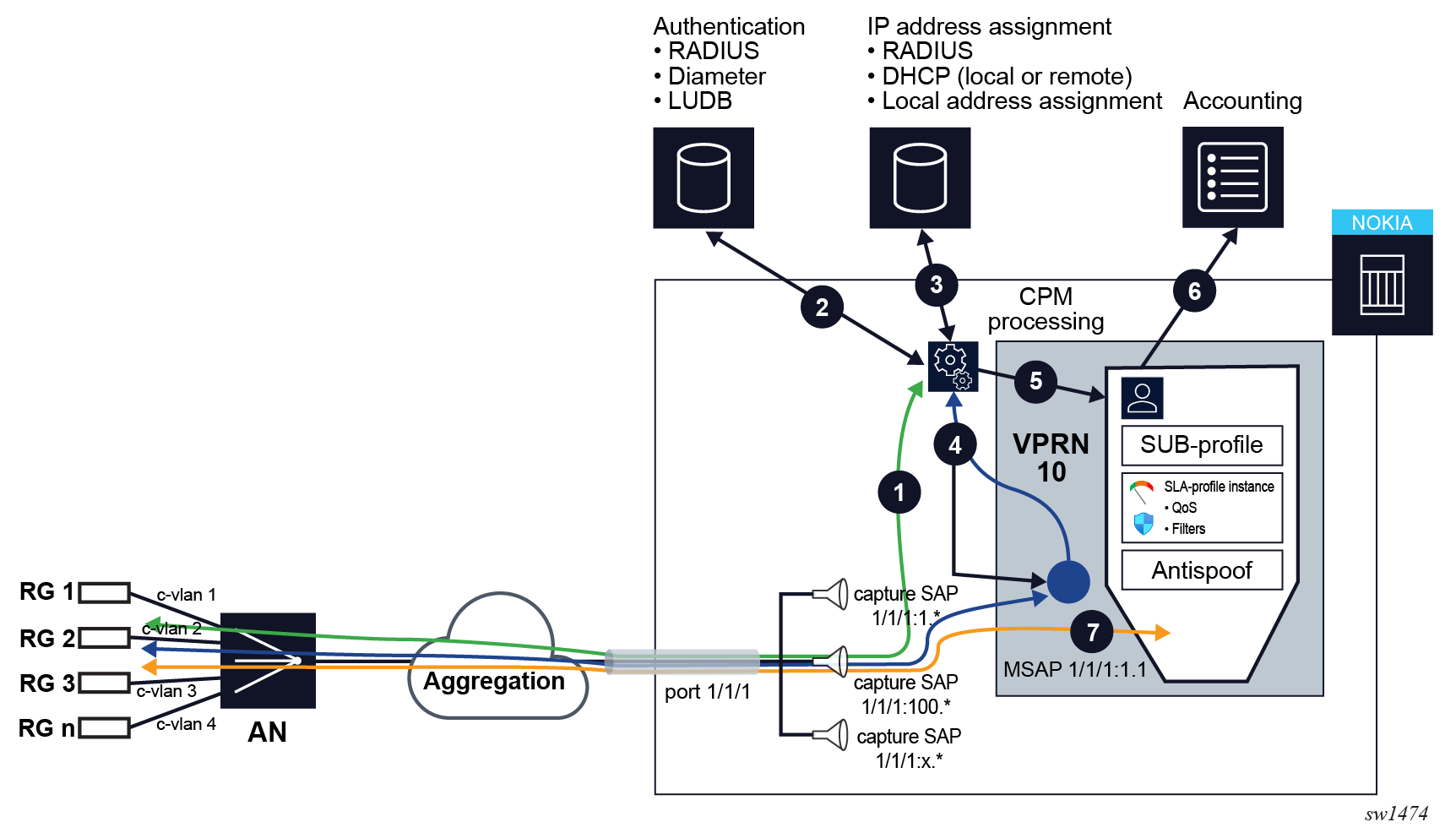
Dynamic instantiation of subscriber sessions
In generic terms, dynamic instantiation of a subscriber session indicates that a limited configuration is required on the node. Configuring subscriber-specific parameters, including the SAP on which subscribers are instantiated, is not required. Instead, shared profiles are configured for multiple subscribers. All specifics for a subscriber, including the profile references, are assigned through authentication and address assignment sources. SAPs are then automatically determined from incoming session initiation traffic (in which a subgroup of the session control2 traffic) arriving on the capture SAP.
This contrasts with static subscribers where everything must be explicitly configured in the node. For information about static sessions, see Static subscriber hosts.
Dynamic instantiation of subscriber sessions shows a high-level workflow of where all parameters are assigned dynamically:
- 1. Session initiation traffic, for example DHCP Discover for IPv4 traffic, arrives on a capture SAP and sent to the control plane.
- 2. Control plane authenticates the user based on information in DHCP Discover (for example Opt82 – circuit-id).
- 3. IP address is allocated to the session.
- 4. Replies are sent back to the user, and the rest of the control traffic is exchanged (DHCP Offer, DHCP Request, DHCP Ack).
- 5. Subscriber session is setup in the system. Managed SAP is derived from the incoming control packets.
- 6. Accounting is optionally started.
- 7. Subscriber session data traffic flows