SR P2MP policy
The Segment Routing (SR) Point-to-Multipoint (P2MP) policy removes the need for the traditional underlay signaling layers like multipoint LDP (mLDP) and P2MP RSVP-TE. A P2MP policy can be instantiated statically using the CLI on the Path Computation Element Client (PCC), or instantiated dynamically using a Path Computation Element (PCE). The PCE uses the Path Computation Element Protocol (PCEP) to program the PCC.
The P2MP policy datapath and forwarding plane use MPLS instructions, similar to mLDP and P2MP RSVP-TE, and are programmed using a replication segment object. The replication segment is a forwarding entity with an incoming label and a set of Outgoing Interfaces (OIF) and labels. A P2MP policy can be used in a Next-Generation Multicast VPN (NG-MVPN) as a provider tunnel.
This functionality is described in the following IETF drafts:
- draft-voyer-pim-sr-p2mp-policy
- draft-voyer-spring-sr-replication-policy
- draft-dhs-spring-sr-p2mp-policy-yang
- draft-hsd-pce-sr-p2mp-policy
- draft-hb-idr-sr-p2mp-policy
SR P2MP policy details
A P2MP policy represents a multicast tree from the root node to a set of leaf nodes, and is a single provider tunnel. A P2MP policy can contain redundant trees from the root to leaf nodes, each with its own preference. This redundancy is implemented using Candidate Paths (CPs). Each CP represents a P2MP tree with its own Traffic Engineering (TE) constraints. The CPs can be optimized based on link failures or IGP optimizations. Each CP can contain multiple P2MP LSPs represented by path instance IDs. The CP can perform make-before-break between these path instances (P2MP LSPs).
A P2MP policy is relevant only on the root node where the P2MP tree is instantiated. The P2MP policy is identified by the tuple <root ID, tree ID>. A P2MP policy, does not include any forwarding information for the P2MP LSP. The policy only contains information about the root and leaf nodes and the TE, which is required to set up the tree from the root to the leaf nodes. The forwarding information is part of the replication segment. The root, transit, and leaf nodes contain replication segments.
Replication segment
A replication segment is the forwarding instruction for a P2MP LSP. It contains the incoming replication Segment Identifier (SID) and a set of OIFs and their corresponding SID or SID list. A replication segment is identified by a tree ID, root ID, and path instance ID (LSP ID) through the root, transit, and leaf nodes.
A second kind of replication segment is a shared replication segment. A shared replication segment is shared between multiple root nodes or P2MP LSPs. For this reason, it does not have a root ID but contains a replication segment identifier, which is within the tree ID. A shared replication segment can be used for Fast Reroute (FRR). Currently, the P2MP policy supports a link protection facility bypass FRR.
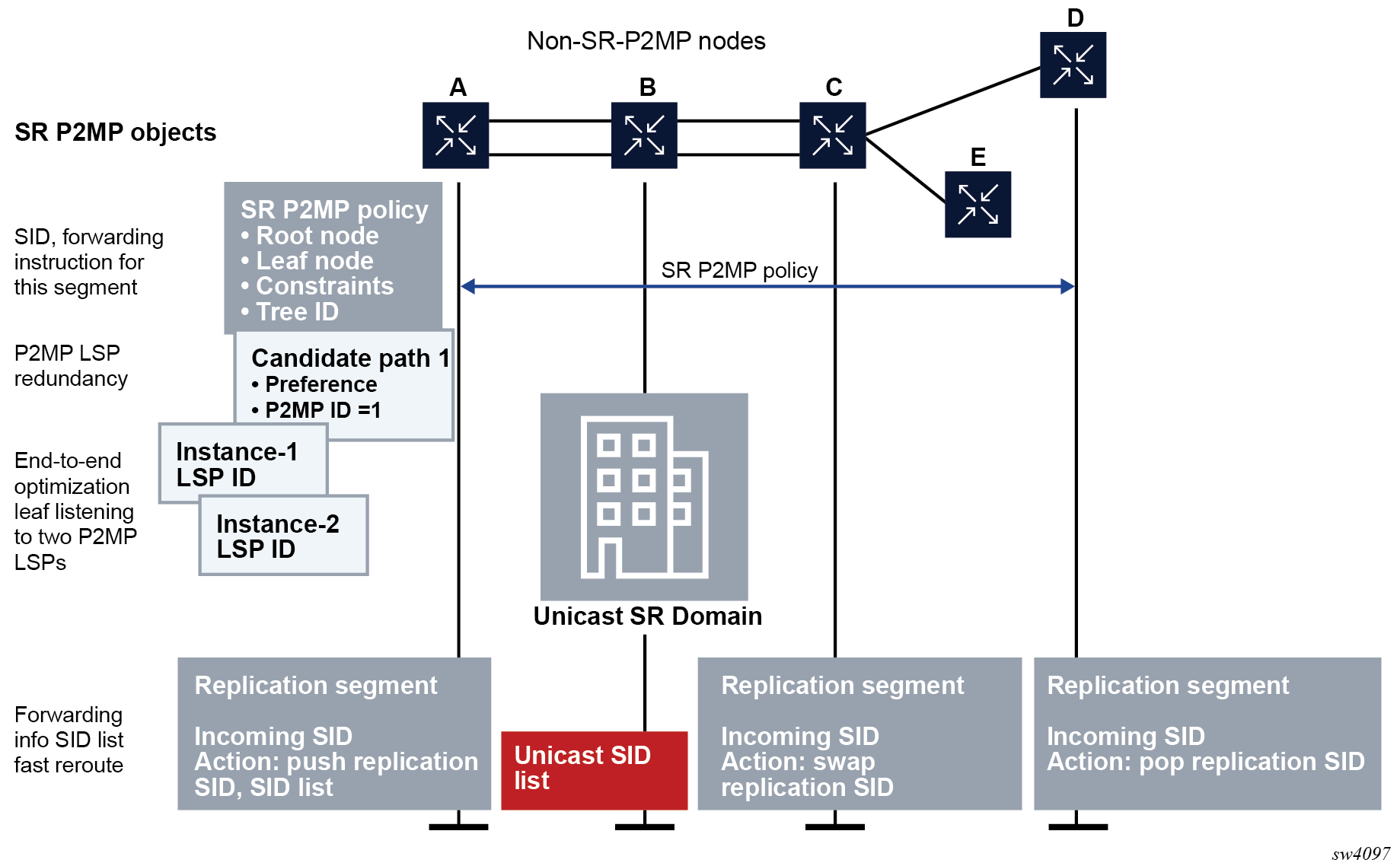
P2MP and replication segment objects
In the following figure, nodes A, C, D, and E are replication-segment capable and B is unicast SR capable (that is, B is not replication-segment capable).
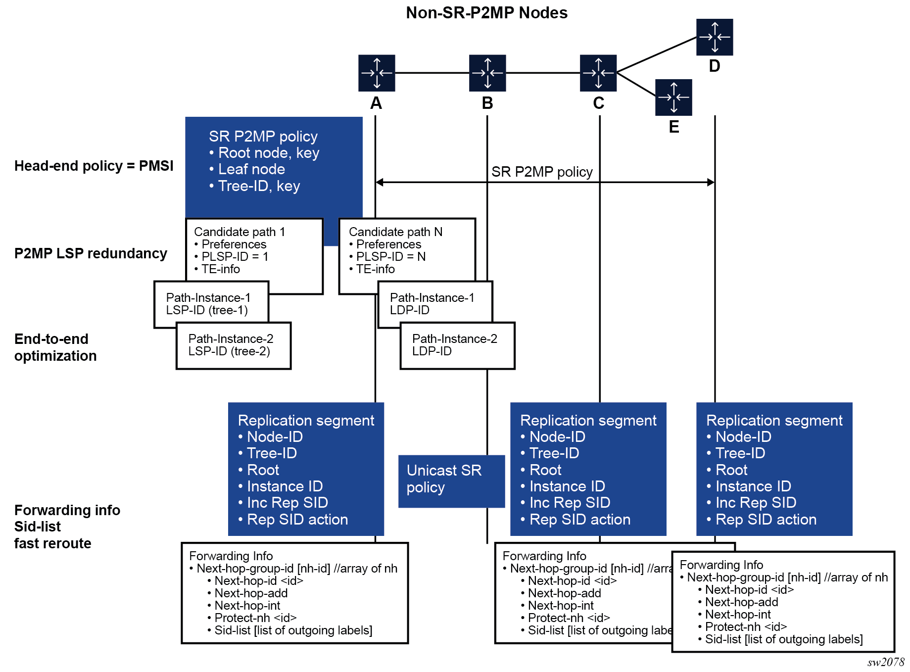
Multiple CPs can exist under a P2MP policy. However, the policy can have only one active CP, based on the CP preference. The highest CP preference is the active CP. The CPs act as tree redundancy.
Multiple path instances can exist under a CP. Each path instance is a P2MP LSP and each instance is presented with an instance ID. Path instances are used for global optimization of the active CP. Each path instance is built using replication segments, which forward P2MP tree information through the network at the root, transit, and leaf nodes. The P2MP policy is correlated to its replication segment by its root ID, tree ID, and instance ID.
The replication segments forward information with one or more OIFs to replicate and forward the PDUs. On the transit and leaf nodes, the incoming replication SID identifies the replication segment and its forwarding information. The replication segment can also contain FRR information for each outgoing interface.
In the following figure, the two replication segments on router A and C can be connected to each other using a unicast SR policy. To do so, the replication segment on router A is programmed with a SID list. The replication SID of router C is at the bottom of the stack and the SR labels connecting A to C are on top of the stack (that is, adjacency SIDs or node SIDs). Node B is not replication-policy capable, so node A pushes the SID list of B and C, where C is the replication SID at the bottom of the stack and B is the node SID.
SR P2MP policy instantiation
The SR P2MP policy can be instantiated either statically on the PCC using the CLI, or dynamically using a PCE.
SR P2MP policy instantiation using the CLI
The CLI can be used to configure a P2MP policy, its CPs, and path instances on the root node. The CLI can also be used to create the replication segments on the root, transit, and leaf nodes. The P2MP policy can be assigned to NG-MVPN Inclusive P-Multicast Service Interfaces (IPMSIs) and Selective PMSIs (SPMSIs).
On each node, each replication segment represents a unique P2MP LSP with the following key: <tree ID, root ID, instance ID>. The instance ID and tree ID are unique to each root.
SPMSI for static P2MP policy
For a static P2MP policy, a single P2MP policy is assigned to an SPMSI. All the (S,G)s that are required to switch to the SPMSI and send an SPMSI AD route use this single P2MP policy. To assign (S,G)s to a different P2MP policy, use multi-stream SPMSIs and assign different (S,G)s to different SPMSIs.
PMSI tree ID advertised by BGP
The tree ID used in MP-BGP to advertise the AD routes is inherited from the P2MP policy assignment to the provider tunnels; it is not generated automatically.
SR P2MP policy instantiation using PCE
NG-MVPN can be configured using the CLI or SNMP on the PCCs.
The root node discovers all leaf nodes through NG-MVPN. The root and leaf nodes information is updated to the PCE using PCEP.
The PCE calculates the shortest path from the root to the leaf nodes and takes into account any programmed constraints. The PCE has an end-to-end view of the network through BGP LS.
After calculating the tree, the PCE downloads the P2MP policy to the root and the replication policies to the root, transit, and leaf nodes.
Updates to the P2MP policy or the replication paths are calculated by the PCE and downloaded accordingly.
SPMSI for PCE P2MP policy
When the root node listens to the MP-BGP SPMSI AD routes and determines that a set of (S,G)s are interested in an SPMSI, it sends an update message to the PCE with the <tree ID, root ID> of the SPMSI AD route and the leaf that is interested in joining this SPMSI. The PCE uses this information to build a P2MP policy for that specific tree ID and downloads it to be used for an SPMSI.
Configuration examples
This section provides examples to configure an MVPN service with SR P2MP policies for SPMSIs and IPMSIs. The configuration examples use the following network.
node-2-(100.101.1.x/24)---P-(101.102.1.x/24)----Leaf-1
|--(101.103.1.x/24)----Leaf-2
The following are the network settings:
- Node-2 is 100.0.0.100.
- P is 100.0.0.101.
- Leaf-1 is 100.0.0.102.
- Leaf-2 is 100.0.0.103.
The following example shows a reserved label block configured (in this example, ‟treeSID”), from which the Tree Segment ID (tree-SID) labels are allocated.
Configure a reserved label block for MPLS labels (MD-CLI)
[ex:/configure router "Base" mpls-labels]
A:admin@node-2# info
    reserved-label-block "treeSID" {
        start-label 30000
        end-label 30999
    }
Configure a reserved label block for MPLS labels (classic CLI)
A:node-2>config>router>mpls-labels# info
----------------------------------------------
            reserved-label-block "treeSID"
                start-label 30000 end-label 30999
            exit
The following example shows the reserved label block enabled for SR P2MP.
Enable a reserved label block for SR P2MP (MD-CLI)
[ex:/configure router "Base" p2mp-sr-tree]
A:admin@node-2# info
    reserved-label-block "treeSID"
Enable a reserved label block for SR P2MP (classic CLI)
A:node-2>configure>router>p2mp-sr-tree# info
----------------------------------------------
        reserved-lbl-block "treeSID"
The following example shows a P2MP policy configured with a tree on the node-2 PE. Two policies are configured, one for an IPMSI and one for an SPMSI.
Configure a P2MP policy on the node with associated CP and path instance (MD-CLI)
[ex:/configure router "Base" p2mp-sr-tree]
A:admin@node-2# info
...
    admin-state enable
    p2mp-policy "IPMSI-VPRN1" {
        root-address 100.0.0.100
        tree-id 9000
        candidate-path "Primary-path" {
            active-instance 1
            preference 1000
            path-instances 1 {
                instance-id 1000
            }
        }
    }
    p2mp-policy "SPMSI-VPRN1" {
        root-address 100.0.0.100
        tree-id 9001
        candidate-path "Primary-path" {
            active-instance 1
            preference 1000
            path-instances 1 {
                instance-id 1000
            }
        }
    }
Configure a P2MP policy on the node with associated CP and path instance (classic CLI)
A:node-2>config>router>p2mp-sr-tree# info
----------------------------------------------
...
            p2mp-policy "IPMSI-VPRN1"
                root-address 100.0.0.100
                tree-id 9000
                candidate-path "Primary-path"
                    preference 1000
                    path-instances
                        index 1 instance-id 1000
                    exit
                    active-instance 1
                    shutdown
                exit
                shutdown
            exit
            p2mp-policy "SPMSI-VPRN1"
                root-address 100.0.0.100
                tree-id 9001
                candidate-path "Primary-path"
                    preference 1000
                    path-instances
                        index 1 instance-id 1000
                    exit
                    active-instance 1
                    shutdown
                exit
                shutdown
            exit
            no shutdown
The following examples shows the P2MP policies assigned to NG-MVPN on the node. BGP must be established between the node-2 and leaf routers using IPv4/IPv6 MVPN Assured Forwarding (AF). The tree ID configured in the P2MP policies is used to advertise in the BGP Provider Tunnel Attribute (PTA) field.
Assign P2MP policies to NG-MVPN (MD-CLI)
[ex:/configure service vprn "1"]
A:admin@node-2# info
    admin-state enable
    customer "1"
    pim {
        rp {
            ipv4 {
                bsr-candidate {
                    admin-state enable
                }
                rp-candidate {
                   admin-state enable
                }
            }
        }
    }
    mvpn {
        c-mcast-signaling bgp
        auto-discovery {
            type bgp
        }
        vrf-target {
            unicast true
        }
        provider-tunnel {
            inclusive {
                p2mp-sr {
                    admin-state enable
                    static-policy-mpls "IPMSI-VPRN1"
                }
            }
            selective {
                data-threshold {
                    group-prefix 231.0.0.0/24 {
                        threshold 10
                    }
                }
                p2mp-sr {
                    admin-state enable
                    static-policy-mpls "SPMSI-VPRN1"
                }
                data-threshold 231.0.0.0/24 10

            }
        }
    }
    bgp-ipvpn {
        mpls {
            admin-state enable
            route-distinguisher "70:70"
            vrf-target {
                community "target:70:70"
            }
            auto-bind-tunnel {
                resolution filter
                resolution-filter {
                    sr-isis true
                }
            }
        }
    }
    interface "to14" {
    }
Assign P2MP policies to NG-MVPN (classic CLI)
A:node-2>config>service>vprn# info
----------------------------------------------
...
            interface "to14" create
            exit
            bgp-ipvpn
                mpls
                    auto-bind-tunnel
                        resolution-filter
                            sr-isis
                        exit
                        resolution filter
                    exit
                    route-distinguisher 70:70
                    vrf-target target:70:70
                    no shutdown
                exit
            exit            pim
                rp
                    static
                    exit
                    bsr-candidate
                        no shutdown
                    exit
                    rp-candidate
                        no shutdown
                    exit
                exit
                no shutdown
            exit
            mvpn
                auto-discovery default
                c-mcast-signaling bgp
                provider-tunnel
                    inclusive
                        p2mp-sr
                            static-policy-mpls " IPMSI-VPRN1"
                            no shutdown
                        exit
                    exit
                    selective
                        p2mp-sr
                            static-policy-mpls " SPMSI-VPRN1"
                            no shutdown
                        exit
                        data-threshold 231.0.0.0/24 10
                    exit
                exit
                vrf-target unicast
                exit
            exit
            no shutdown
You must configure the corresponding replication segment and forwarding instructions on the node, transit, and leaf nodes for the P2MP policies. The following example shows the configuration on the node.
Configure replication segment and forwarding instructions on the node (MD-CLI)
[ex:/configure router "Base" p2mp-sr-tree]
A:admin@node-2# info
...
    replication-segment "IPMSI-VPRN1-NODE-2" {
        admin-state enable
        instance-id 1000
        root-address 100.0.0.100
        tree-id 9000
        segment-routing-mpls {
            sid-action push
            downstream-nodes 1 {
                admin-state enable
                next-hop-address "100.101.1.2"
                label {
                    sid-list 1 {
                        replication-sid 30000
                    }
                }
            }
        }
    }
    replication-segment "SPMSI-VPRN1-node-2" {
        admin-state enable
        instance-id 1000
        }        root-address 100.0.0.100
        tree-id 9001
        segment-routing-mpls {
            sid-action push
            downstream-nodes 1 {
                admin-state enable
                next-hop-address "100.101.1.2"
                label {
                    sid-list 1 {
                        replication-sid 30001
                    }
                }
            }
        }
    }
Configure the replication segment and forwarding instructions on the node (classic CLI)
A:node-2>configure>router>p2mp-sr-tree# info
----------------------------------------------
...
        replication-segment "IPMSI-VPRN1-NODE-2"
            root-address 100.0.0.100
            tree-id 9000
            instance-id 1000
            segment-routing-mpls
                sid-action push
                downstream-nodes "1"
                    next-hop-address 100.101.1.2
                    replication-sid 30000
                    shutdown
                exit
            exit
            shutdown
        exit
        replication-segment "SPMSI-VPRN1-NODE-2"
            root-address 100.0.0.100
            tree-id 9001
            instance-id 1000
            segment-routing-mpls
                sid-action push
                downstream-nodes "1"
                    next-hop-address 100.101.1.2
                    replication-sid 30001
                    shutdown
                exit
            exit
            shutdown
        exit
        shutdown
The following example shows the configuration of the replication segment for IPMSI on the P router . The SPMSI replication router on the P router is configured in the same way, but with a tree ID of 9001 and an incoming SID of 30001.
Configure a replication segment for IPMSI on the P router (MD-CLI)
[ex:/configure router "Base" p2mp-sr-tree]
A:admin@node-2# info
    admin-state enable
    reserved-label-block "treeSID"
    replication-segment "rs-IPMSI-VPRN1-100.0.0.100" {
        admin-state enable
        instance-id 1000
        root-address 100.0.0.100
        tree-id 9000
        segment-routing-mpls {
            incoming-sid 30000
            sid-action swap
            downstream-nodes 1 {
                admin-state enable
                # toleaf1
                next-hop-address "101.102.1.2"
                label {
                    sid-list 1 {
                        replication-sid 30000
                    }
                }
            }
            downstream-nodes 2 {
                admin-state enable
                # toleaf2
                next-hop-address "101.103.1.2"
                label {
                    sid-list 1 {
                        replication-sid 30000
                    }
                }
            }
        }
    }
Configure a replication segment for IPMSI on the P router (classic CLI)
A:node-2>configure>router>p2mp-sr-tree# info
----------------------------------------------
...
        reserved-lbl-block "treeSID"
        replication-segment "rs-IPMSI-VPRN1-100.0.0.100"
            root-address 100.0.0.100
            tree-id 9000
            instance-id 1000
            segment-routing-mpls
                sid-action swap
                incoming-sid 30000
                downstream-nodes "1"
                    next-hop-address 101.102.1.2 //toleaf-1
                    replication-sid 30000
                    no shutdown
                exit
                downstream-nodes "2"
                    next-hop-address 101.103.1.2 //toleaf-2
                    replication-sid 30000
                    no shutdown
                exit
            exit
            no shutdown
        exit
        no shutdown
The following example shows the replication segment on the Leaf-1 router.
Configure a replication segment for the Leaf-1 router (MD-CLI)
[ex:/configure router "Base" p2mp-sr-tree]
A:admin@node-2# info
    admin-state enable
    reserved-label-block "treeSID"
    replication-segment "rs-IPMSI-VPRN1-100.0.0.100" {
        admin-state enable
        instance-id 1000
        root-address 100.0.0.100
        tree-id 9000
        segment-routing-mpls {
            incoming-sid 30000
            sid-action pop
        }
    }
Configure a replication segment for the Leaf-1 router (classic CLI)
A:node-2>configure>router>p2mp-sr-tree# info
----------------------------------------------
        reserved-lbl-block "treeSID"
        replication-segment "rs-IPMSI-VPRN1-100.0.0.100"
            root-address 100.0.0.100
            tree-id 9000
            instance-id 1000
            segment-routing-mpls
                sid-action pop
                incoming-sid 30000
            exit
            no shutdown
        exit
The following example shows the replication segment on the Leaf-2 router.
Configure a replication segment for the Leaf-2 router (MD-CLI)
[ex:/configure router "Base" p2mp-sr-tree]
A:admin@node-2# info
    admin-state enable
    reserved-label-block "treeSID"
    replication-segment "rs-IPMSI-VPRN1-100.0.0.100" {
        admin-state enable
        instance-id 1000
        root-address 100.0.0.100
        tree-id 9000
        segment-routing-mpls {
            incoming-sid 30000
            sid-action pop
        }
    }
Configure a replication segment for the Leaf-2 router (classic CLI)
A:node-2>configure>router>p2mp-sr-tree# info
----------------------------------------------
...
        reserved-lbl-block "treeSID"
        replication-segment "rs-IPMSI-VPRN1-100.0.0.100"
            root-address 100.0.0.100
            tree-id 9000
            instance-id 1000
            segment-routing-mpls
                sid-action pop
                incoming-sid 30000
            exit
            no shutdown
        exit
Administrative behavior of tree-SID
This section describes the administrative behavior of the SR P2MP policy and the CP.
Candidate path selection criteria
The active CP is chosen as follows.
The higher value protocol origin is selected.
The existing installed path is preferred.
The lower value of originator is selected.
The higher value of discriminator is selected.
The CLI static configuration has a protocol origin value of 30. This value is not configurable.
The CLI originator value is <0, 0.0.0.0>.
From the CLI perspective, the CP selection is as follows.
If the P2MP policy is operational and has an operational CP, the following handling applies.
If a CP with a higher preference is configured and becomes operational, the users should switch to it.
If the current CP is the highest preference and another CP with the same preference is configured, the users should stay on the current CP.
If the P2MP policy is administratively disabled, then administratively enabled, and there are multiple CPs with the same preference, the CP that was created last should be chosen. The show command for the CP displays the creation time.
Candidate path operational status
The CP operational status changes to down if at least one of the following conditions becomes true:
The CP has no active instance.
The CP is administratively disabled.
The replication segment correlating to the CP on the root is operationally down or does not exist.
P2MP policy operational status
If at least one of the following conditions becomes true, the operational status of the P2MP policy and the status of the PMSI corresponding to the P2MP policy change to down:
All the CPs in the P2MP policy are operationally down.
The P2MP policy is administratively disabled.
Replication segment operational status
A replication segment is operationally down when one of the following is true:
all its next-hops (NHs) are operationally down, including the FRR NHs
no NHs are configured
The replication segment is operationally up if at least one NH is operationally up on the replication segment.
FRR behavior
Only facility bypass and link protection are supported for a P2MP policy. Node protection is not supported. The facility bypass can be created using shared replication segments. Shared replication segments do not have a tree ID. They are identified using a replication segment identifier within the tree ID.
At the Point of Local Repair (PLR), the primary replication segment has a protection next hop. This protection next-hop has a second OIF with its own outgoing label, which is used for the facility protection tunnel.
The facility protection tunnel can consist of multiple transit nodes until the tunnel reaches the Merge Point (MP). Replication segments are configured on these transit nodes to complete the facility protection tunnel. Multiple P2MP trees can share the facility protection tunnel at the PLR. The facility protection tunnel uses the implicit null label (see Implicit null case) or an actual label at the Penultimate Hop Popping (PHP) node (see Non-implicit null case).
Implicit null case
If the implicit null label is used, the protection tunnel label is popped and the tree-SID P2MP LSPs are forwarded to the MP with the tree SID label.
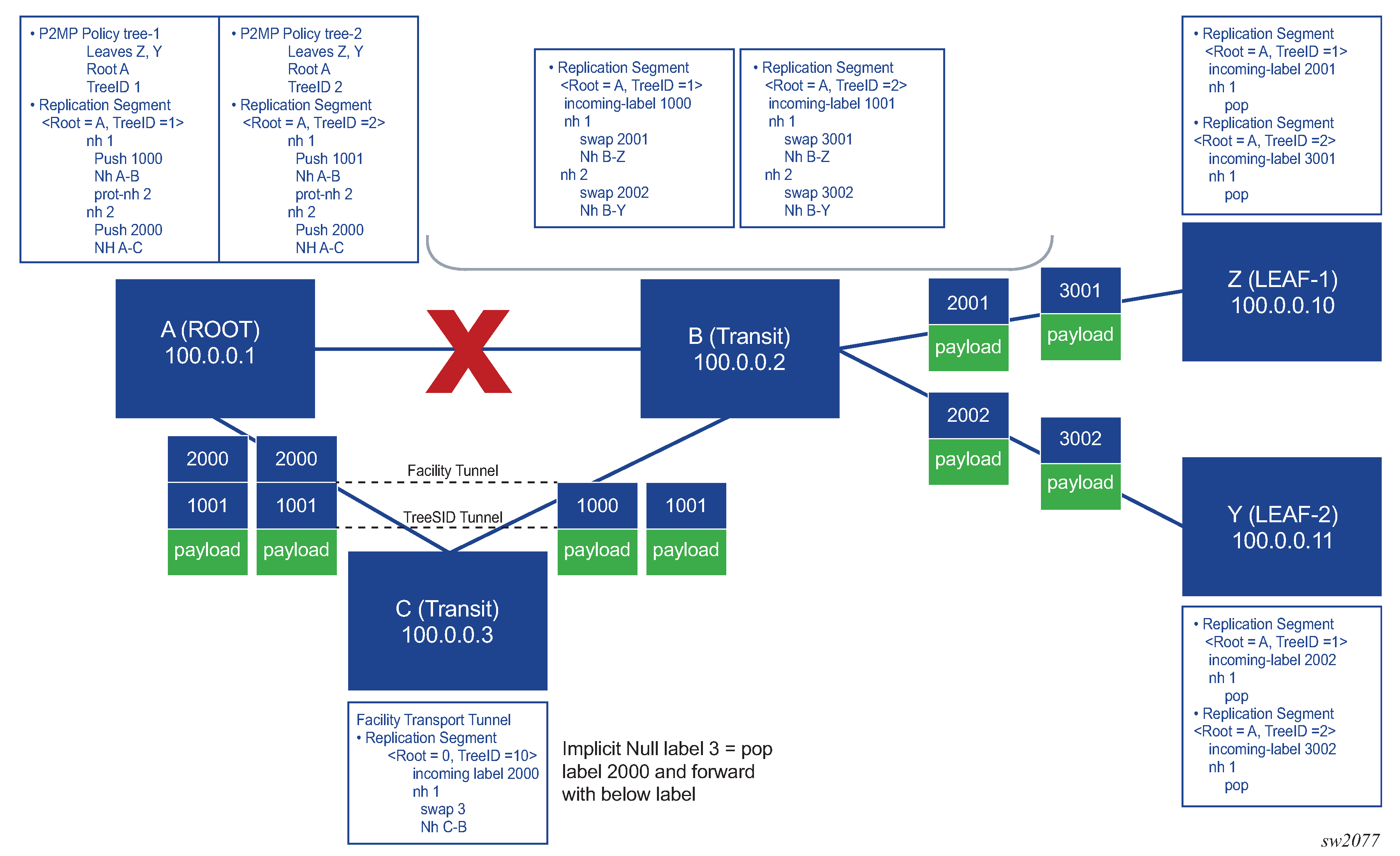
In the following figure, node A is protecting link A-B through node C, so the facility protection tunnel is set up through node C. Node C is a PHP node and is programmed to swap the facility protection label with implicit null (label 3).
After a failure on the A-B link, node A pushes label 2000 as indicated in the protection next hop programmed in the replication segment for trees 1 and 2. Trees 1 and 2 share the same facility protection tunnel (label 2000). The packet is forwarded to node C, where node C pops the protection next hop and forwards the packet to node B with a replication SID on top of the packet.
Non-implicit null case
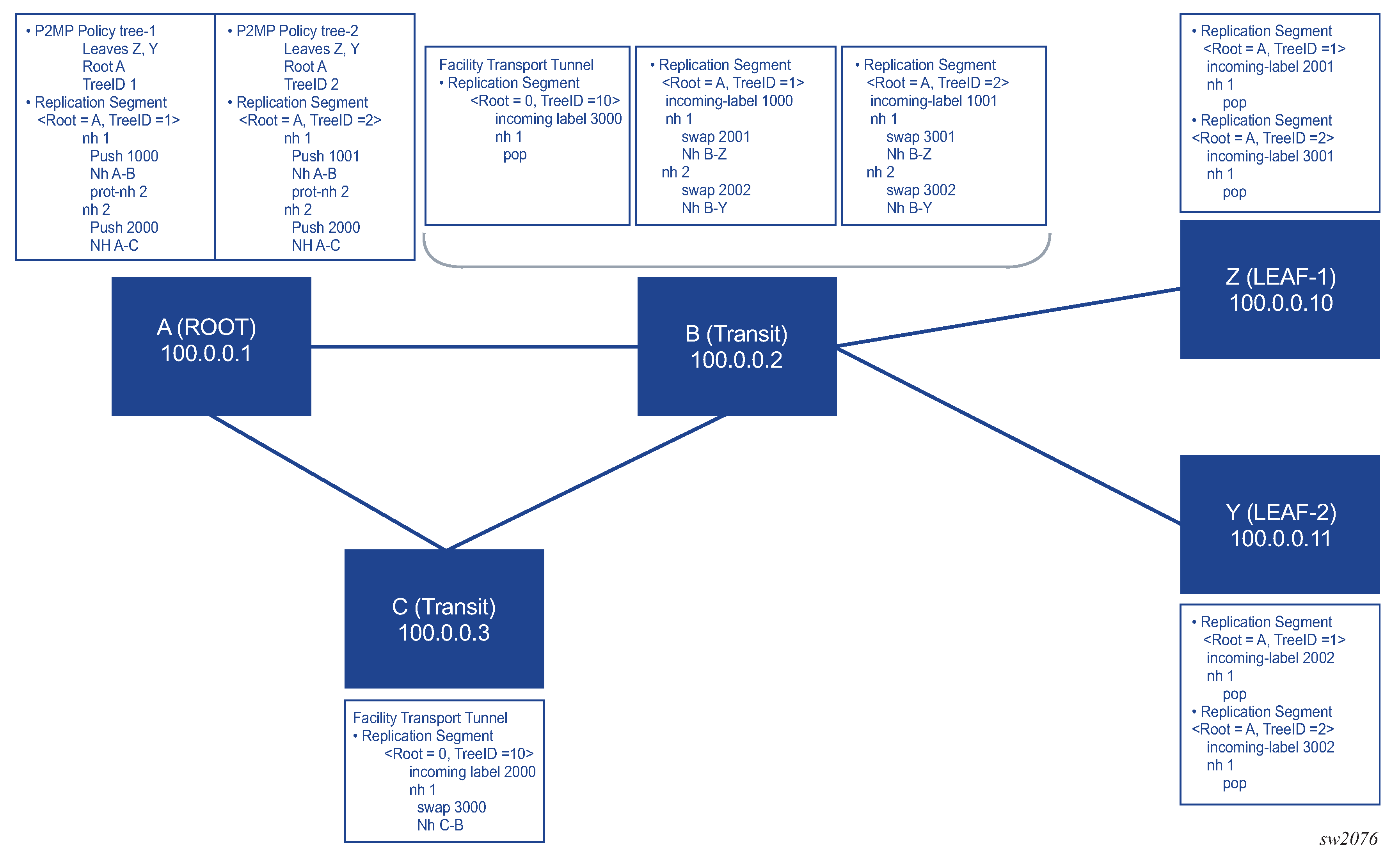
If an implicit null label on the PHP node is not used, a replication segment is needed on the MP to pop the facility protection label and forward the underlying traffic based on the tree-SID label.
In the following figure, node A is protecting the A-B link through node C, so the facility protection tunnel is set up through node C. Node C is a PHP node and is programmed to swap the facility protection label with label 3000.
After a failure on link A-B, node A pushes label 2000 as indicated by the protection next-hop programmed in the replication segment for trees 1 and 2. The packet is forwarded to node C, where node C swaps the protection label with label 3000 for both tree 1 and tree 2, and forwards the packet to node B. Node B has a replication segment for the facility protection tunnel, which has an action of pop 3000. After popping 3000 on node B, the tree-SID label for label 1 and label 2 is exposed and the corresponding replication segment is found and executed.
FRR recovery behavior
After the primary path is recovered, the P2MP LSP switches back to the primary path and away from the protection next-hop (FRR). This switch back to primary may cause a brief traffic outage.
The replication SID next-hops send optimistic ARP to populate the ARP table. If the next-hop MAC address is not found in the ARP table (that is, the address is not populated by BFD, IGP, or any other packet), the optimistic ARP populates the ARP table. The reversion from FRR to the primary next-hop happens only if the primary path ARP entry is found in the ARP table.
BFD behavior
Use the commands in the following context to enable BFD for the replication segment next hops.
configure router p2mp-sr-treeBFD is enabled at the P2MP SR tree level. The P2MP SR tree registers itself with the current available BFD session. The BFD sessions need to be enabled using other protocols. For example, static route, OSPF, or IS-IS can enable the BFD session on an interface. The replication segments are registered with these BFD sessions. The replication segments cannot initiate a BFD session and rely on other protocols to initiate the BFD session because a replication segment is a unidirectional entity, while BFD is a bidirectional protocol.
When BFD is enabled under the p2mp-sr-tree context, all replication next hops that are using an L3 interface with BFD enabled on that interface register with the BFD module. If the BFD status on the L3 interface goes down, any replication segment next hop that is using that L3 interface goes operationally down. This operationally down status of the next hop within a replication segment can cause an FRR.
Only single-hop BFD is supported. BFD for unnumbered interfaces is not supported.
For IPv6, protocols such as OSPF or LDP create a BFD session to the link local interface. A static route can create a BFD session to link local or global IPv6 addresses. To use BFD for IPv6 next-hops within a replication segment, the replication segment needs to be configured with a link local next-hop for protocols that create the BFD session to the link local address. This way, the replication segment next hop finds a BFD session created by one of these protocols.
Maximum SPMSI behavior
The maximum P2MP SPMSI value configured under an MVPN selective provider tunnel does not affect any established SPMSIs. It only affects new spawning SPMSI counts.
If any existing SPMSIs are above the maximum P2MP SPMSI threshold, no new SPMSIs are spawned until the number of SPMSIs goes below the threshold.
Global optimization of P2MP policy and MBB behavior
Global optimization of the P2MP policy CP is supported, in addition to local FRR, where the protection next-hop is downloaded by the replication segment and the FRR action is triggered by a port failure or BFD failure.
To use the global optimization behavior, the user creates another instance under the P2MP policy. Appropriate replication segments must also be created for this optimized instance. After the entire tree is created, the active instance under the CP is set to this new, optimized instance and a switch from the previous instance to this optimized instance is performed. While the switch is in progress, the MVPN on the leaf is accepting traffic from both instances of the CP. After the switch is complete, the old instance can be deleted from the candidate path and its replication segments can be removed.
Global optimization of PCEP behavior
Global optimization is supported on the PCE. Local optimization of a replication segment using PCEP is not supported. If the PCE calculates an optimized path for a candidate path, that path instance is different from the current path instance. For this reason, a candidate path contains two path instances. The PCE must download a new path instance with an LSP ID of 0 and the PLSP ID of the current CP. This behavior applies to replication segments only.
When the current path instance is modified from the PCE to the PCC, the PCC-assigned LSP ID and PLSP ID are sent from the PCE to the PCC. This behavior ensures that the LSP ID of the replication segment for the existing path instances does not change.
PCEP behavior
You can clear all states on the PCC, including replication segments and P2MP policies.
The state of the P2MP LSP on the PCC is operationally up as long as there is one valid OIF and up for that LSP.
Use the following command to clear all states on the PCC:
- MD-CLI
configure router p2mp-sr-tree admin-state disable - classic
CLI
configure router p2mp-sr-tree shutdown
PCE pop with next-hop 127.0.0.0/8 or ::1
For a PCE, to program the datapath with a pop action, the next hops must be programmed as 127.0.0.0/8 or IPv6 ::1. If the replication segment next-hop has no information, the next hop is reported to the PCE with status down.
For CLI-initiated replication segments, the next-hop label action can be set to pop, and the next hop does not need to be programmed as 127.0.0.0/8 or ::1.
P2MP policy special considerations
For interfaces that are not configured as unnumbered, the next-hop used in the replication segment must be a direct (local) next-hop. The replication segment cannot resolve indirect next-hops to a downstream router loopback or system IP address.
The FRR outage time can exceed 50 ms when a node has a large number of replication segments that are using a protection tunnel for FRR.
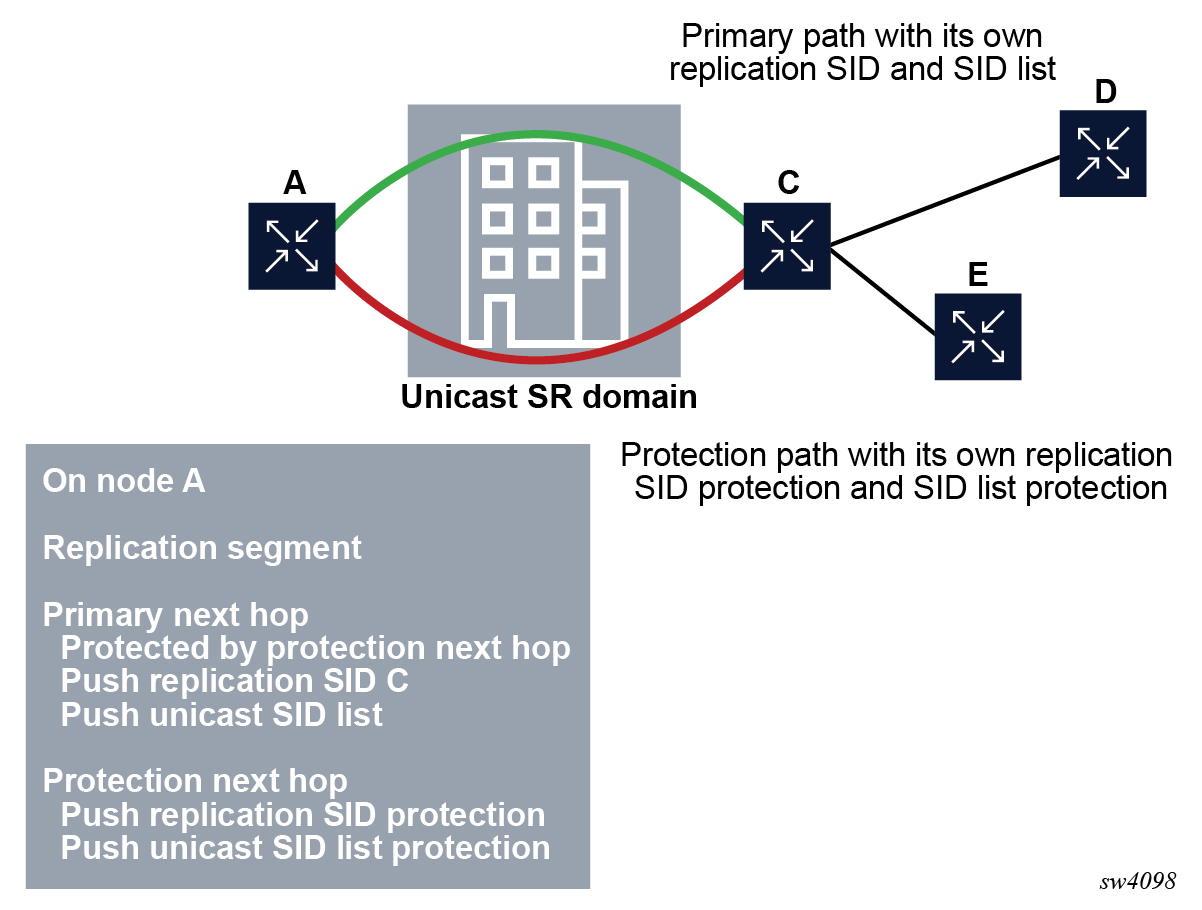
Replication segment steering through a unicast SR network
When a unicast SR network is present between two replication SIDs, it is possible to connect the two replication SIDs through a unicast SID list, as shown in the following figure. The SID list can be a list of adjacency or node SIDs that provides a traffic-engineered path though the unicast domain to connect the two replication SIDs.
The unicast SID list can be configured by listing the node or adjacency SIDs under a replication segment. Even if two replication segments are connected directly, the egress interface or the next hop can be programmed using a SID list. For example, an adjacency SID can be used as a mechanism to steer the packet out of a local interface.
The unicast fast reroute functionality and Equal Cost Multipath (ECMP) functionality are not available on the egress replication segment node on which the SID list is configured. However, the next downstream node in the unicast SR domain can take advantage of all unicast SR TE and resiliency features, for example, Loop-Free Alternate (LFA), Remote Loop-Free Alternate (RLFA), or Topology-Independent Loop-Free Alternate (TI-LFA).
On the egress replication segment node, the protection next hop can be configured using a replication SID. In addition, a SID list can be used in any next-hop object under the replication segment, including the protection next-hop object, as shown in the following figure.
Tree-SID OAM ping
Multiple candidate paths (CPs) can exist under a P2MP policy acting as tree redundancy, but only one CP can be active in the P2MP policy based on its CP preference. Multiple path instances can exist under a CP, with each path instance being a P2MP LSP and with each instance having an instance ID. SR OS can send ICMP ping packets over each of these path instances for both active and non-active instances on all CPs.
SR OS implementation supports version 3 of the draft-ietf-pim-p2mp-policy-ping.
Tree-SID configuration (classic CLI)
A:node-2>config>router# info
...
#--------------------------------------------------
echo "TREE SID Configuration"
#--------------------------------------------------
            p2mp-sr-tree
                reserved-lbl-block "treeSID"
                p2mp-policy "ipmsi-1"
                    root-address 100.0.0.100
                    tree-id 9000
                    candidate-path "Primary-path-1"
                        preference 1000
                        path-instances
                            index 1 instance-id 1000
                        exit
                        active-instance 1
                        no shutdown
                    exit
                    candidate-path "Primary-path-2"
                        preference 500
                        path-instances
                            index 1 instance-id 1010
                        exit
                        path-instances
                            index 2 instance-id 1011
                        exit
                        active-instance 1
                        no shutdown
                    exit
                    no shutdown
                exit
            exit
...Using the preceding configuration as an example, the oam p2mp-lsp-ping command can be used in the following ways.
Use the following command to test the "Primary-path-1" instance-id 1000.
A:node-2# oam p2mp-lsp-ping p2mp-policy root-address 10.0.0.100 root-tree-id 9000 instance-id 1000Use the following command to test the "Primary-path-2" instance-id 1010.
A:node-2# oam p2mp-lsp-ping p2mp-policy root-address 10.0.0.100 root-tree-id 9000 instance-id 1010Use the following command to test the "Primary-path-2" instance-id 1011.
A:node-2# oam p2mp-lsp-ping p2mp-policy root-address 10.0.0.100 root-tree-id 9000 instance-id 1011P2MP SR policy ping output
A:node-2# oam p2mp-lsp-ping p2mp-policy root-address 10.0.0.100 tree-id 9000 instance-id 1011 detail
88 bytes MPLS payload
===================================================
LEAF Information
===================================================
From            RTT                 Return Code
---------------------------------------------------
10.20.1.2                       =2.59ms                                      EgressRtr(3)
10.20.1.1                       =2.68ms                                      EgressRtr(3)
10.20.1.6                       =3.03ms                                      EgressRtr(3)
10.20.1.5                       =4.89ms                                      EgressRtr(3)
===============================================================================

Total Leafs responded = 4
          round-trip min/avg/max  = 2.59 / 3.29 / 4.89 ms

Responses based on return code:
      EgressRtr(3)=4
SID list support
The Tree-SID OAM feature can support the following:
- Testing a tree, with each replication segment directly connected to each other, and the outgoing label on each outgoing interface (OIF) being the replication SID.
- SID list or steering through an Adjacency Segment Identifier (Adj-SID). In this case, there is a SID list above the replication SID. This SID list can be a single Adj-SID used for steering the replication SID out of an interface or it can be a SID list with multiple node and Adj-SIDs used to connect two replication segments through a unicast domain.
Tree-SID SRv6
Implementation Overview
- All the routers in a P2MP tree must support tree-SID SRv6.
- The replication routers cannot be connected via a unicast domain and SID list.
In addition, tree-SID SRv6 currently only supports basic SID and no other SRv6 SID formats.
- behaves as an end.x, where the multicast payload is extracted and forwarded to the local host, in the case of bud and leaf routers
- identifies the instructions for a transit router, where the outgoing interface constructs the new outgoing SRv6 header
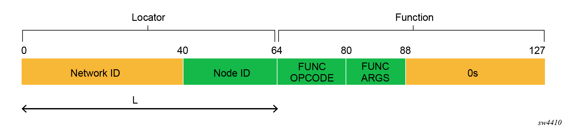
Tree-SID SRv6 header
Similarly to other SRv6 headers, an SRv6 tree-SID header uses a locator and a function to do the following:
- A locator from prefix /1 to /96 bits is used to forward the packet to the next replication segment.
- A function of length 16 bits or 20 bits is used to identify a replication segment and the multicast state.
The following figure shows an example of the SRv6 tree-SID header. The SRv6 tree-SID uses a different locator on the same node to deconflict the SID for multicast as compared to unicast. The function length is 16-bit, but SR OS supports up to 20 bits, using some of the ARGS bits to scale higher.
Tree-SID SRv6 implementation details
The SR OS SRv6 tree-SID is implemented as follows:
- supported only as selective PMSI and inclusive PMSI in NG-MVPN
- supports manual configuration using CLI only and does not support PCEP
- supports only BGP IPv4 neighboring
- supports only multicast source resolution via BGP-IPVN MPLS in a VPRN, not via
BGP-IPVN segment-routing-6Note: BGP-IPVN segment-routing-6 cannot resolve the source IP currently for tree-SID SRv6.
- no support for SID-LIST, which means replication segments must be directly connected
- no support for tree-SID protection nexthop of SRv6 LFA, which means tree-SID recovery is based on IGP convergence if the primary outgoing interface is down
- no support for BFD
- UMH redundancy support only when UMH route selection is configured to use the unicast route preference (configure service vprn mvpn umh-selection command)
- for simpler debugging, recommend the function value be constant for the tree, to identify the tree end-to-end from the root to all the leaves
- distributes tree-SID SRv6 locator via IGP and is pingable
Implementation use case 1
The following figure shows replication segments between the Replication segment 1 (R1) node to the R2 node, and the R2 node to R3, R4, and R5 nodes.

Implementation use case 2
- Node k has a classic IPv6 loopback address 2001:db8::k/128, which is advertised in the IGP.
- The address 2001:db8:cccc::/48 is dedicated to the internal SRv6 SID space.
- Node k has 2001:db8:cccc:k::/64 for its local SID space.
- Node k advertises 2001:db8:cccc:k::/64 in its IGP.
- Function :Fn:: is for End.Replication.
In the following figure, the R1 node encapsulates the multicast stream from the source into an SRv6 tree-SID, and builds the SRv6 SID with the R2 node as locator and F2 as the function (DA:2001:db8:cccc:2:F2::0). The R1 node forwards the packet toward the R2 node based on the locator.
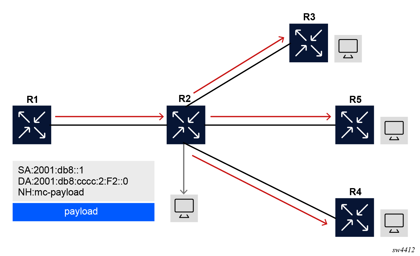
Implementation use case 3
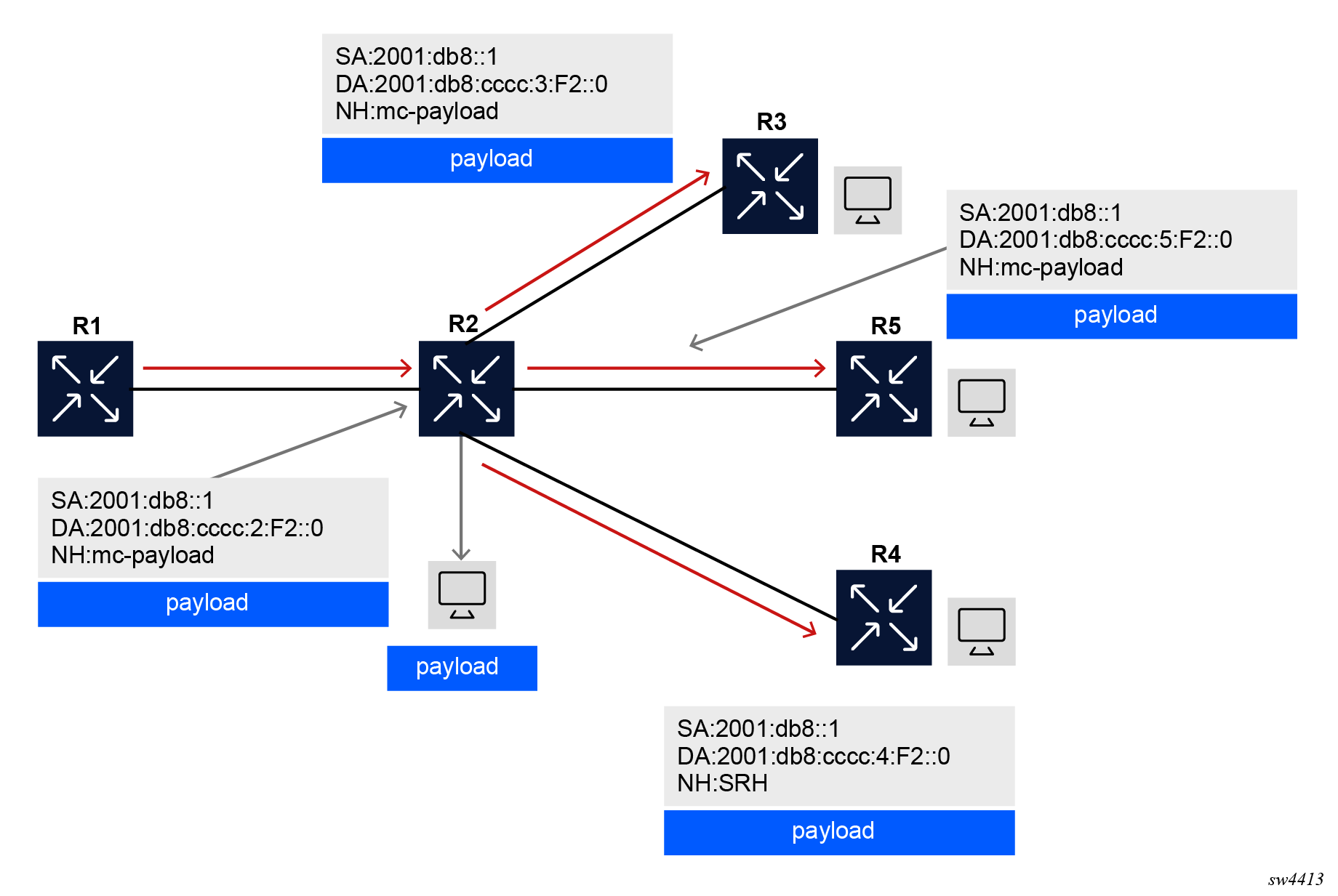
In the following figure, the R2 node (replication SID: 2001:db8:cccc:2:F2::0, state: leaf) receives the packet and based on the locator, it uses the function value to find the multicast state for function F2. Based on the multicast state (replication segment), the R2 node forwards the packet to the R3 node (2001:db8:cccc:3:F2::0), the R4 node (2001:db8:cccc:4:F2::0), and the R5 node (2001:db8:cccc:5:F2::0). The R2 node also builds a new IPv6 destination using the corresponding locator of each router. The R2 node keeps the function as F2.
The R2 node also acts as end-x for the locally connected host. In this capacity it removes the SRv6 header and forwards the packet to the locally connected host.
Implementation use case 4
In the following figure, when the R3 node (Replication SID: 2001:db8:cccc:3:F2::0, state: leaf) receives the packet with its own locator and function F2, it realizes that it is the end.x for the locally connected host. The R3 node then removes the SRv6 header and forwards the payload to the locally connected host. The R4 node (Replication SID: 2001:db8:cccc:4:F2::0, state leaf) and the R5 node (Replication SID: 2001:db8:cccc:5:F2::0, state: leaf) follow the same procedure as the R3 node.

Tree-SID SRv6 configuration guidelines
The following guidelines apply when configuring replication segments in the SR OS system:
- The system supports one replication segment with the same root IP address, tree ID
and instance ID, of either type MPLS or SRv6 depending on its configuration. Use the
commands in the following contexts to configure the replication-segment settings for
SRv6 or
MPLS.
configure router p2mp-sr-tree replication-segment segment-routing-v6 configure router p2mp-sr-tree replication-segment segment-routing-mpls - P2MP policies can only associate with replication segments of the same type, either
MPLS or SRv6. When an MPLS or SRv6 P2MP policy is assigned to the MVPN provider
tunnel in the following contexts, the MVPN tunnel becomes the assigned type, either
SRv6 or
MPLS.
configure service vprn mvpn provider-tunnel inclusive p2mp-sr static-policy-srv6 configure service vprn mvpn provider-tunnel inclusive p2mp-sr static-policy-mpls- If there is a mismatch between the replication segment type and the PMSI
type, the PMSI is not operational and the router does not advertise the AD
routes in BGP. Note: The P2MP policy is accepted under the PMSI even if there is a mismatch; the system does not check for mismatch errors.
- If there is no mismatch between RS and PMSI type, the router advertises the BGP route PTA based on this type.
- If there is a mismatch between the replication segment type and the PMSI
type, the PMSI is not operational and the router does not advertise the AD
routes in BGP.
The following example shows P2MP SR tree configuration with SRv6 and MPLS replication segments, P2MP policies, and MVPN provider tunnels.
P2MP-SR-tree configuration (MD-CLI)
[ex:/configure router "Base" p2mp-sr-tree]
A:admin@node-2# info
    admin-state enable
    reserved-label-block "tree_sid_block"
    p2mp-policy "p2mp_policy_8193_10.20.1.3" {
        admin-state enable
        root-address 10.20.1.3
        tree-id 8193
        candidate-path "cp_1" {
            admin-state enable
            active-instance 1
            preference 0
            path-instances 1 {
                instance-id 1
            }
        }
    }
    p2mp-policy "p2mp_policy_8194_10.20.1.3" {
        admin-state enable
        root-address 10.20.1.3
        tree-id 8194
        candidate-path "cp_1" {
            admin-state enable
            active-instance 1
            preference 0
            path-instances 1 {
                instance-id 1
            }
        }
    }
    replication-segment "rs_8193_10.20.1.3_inst_1_mpls" {
        admin-state enable
        instance-id 1
        root-address 10.20.1.3
        tree-id 8193
        segment-routing-mpls {
            sid-action push
            downstream-nodes 1 {
                admin-state enable
                next-hop-address "10.180.3.2"
                label {
                    sid-list 1 {
                        replication-sid 78432
                    }
                }
            }
        }
    }
    replication-segment "rs_8194_10.20.1.3_ins_1_srv6_leaf" {
        admin-state enable
        instance-id 1
        root-address 10.20.1.1
        tree-id 8194
        segment-routing-v6 {
            role leaf
            incoming-sid {
                locator {
                    locator-name "p2mp"
                    function end-replicate
                    function-value 1001
                }
            }
        }
    }
    replication-segment "rs_8194_10.20.1.2_ins_1_srv6_bud" {
        admin-state enable
        instance-id 1
        root-address 10.20.1.2
        tree-id 8194
        segment-routing-v6 {
            role transit
            incoming-sid {
                locator {
                    locator-name "p2mp"
                    function end-replicate
                    function-value 1002
                }
            }
            downstream-nodes 1 {
                admin-state enable
                replication-sid 2001:db8:cccc:202::1002
            }
            downstream-nodes 2 {
                admin-state enable
                replication-sid 2001:db8:cccc:404::1002
            }
        }
    }
    replication-segment "rs_8194_10.20.1.2_ins_srv6_root" {
        admin-state enable
        instance-id 1
        root-address 10.20.1.3
        tree-id 8194
        segment-routing-v6 {
            role root
            downstream-nodes 1 {
                admin-state enable
                replication-sid 2001:db8:cccc:202::1003
            }
        }
    }
    replication-segment "rs_8193_10.20.1.3_ins_1_mpls" {
        admin-state enable
        instance-id 1
        root-address 10.20.1.3
        tree-id 8193
        segment-routing-mpls {
            sid-action push
            downstream-nodes 1 {
                admin-state enable
                next-hop-address "10.180.3.2"
                label {
                    sid-list 1 {
                        replication-sid 78432
                    }
                }
            }
        }
    }
[ex:/configure service]
A:admin@node-2# info
    vprn "1" {
        mvpn {
            provider-tunnel {
                inclusive {
                    p2mp-sr {
                        admin-state enable
                        static-policy-mpls "p2mp_policy_8192_10.20.1.3"
                    }
                }
                selective {
                    data-threshold {
                        group-prefix 224.0.0.0/4 {
                            threshold 1
                        }
                    }
                    p2mp-sr {
                        admin-state enable
                        static-policy-srv6 "mcastTreeSIDPolS"
                        maximum-p2mp-spmsi 4000
                    }
                }
            }
        }
    vprn "2" {
        mvpn {
            provider-tunnel {
                inclusive {
                    p2mp-sr {
                        admin-state enable
                        static-policy-srv6 "mcastTreeSIDPolI"
                    }
                }
                selective {
                    data-threshold {
                        group-prefix 224.0.0.0/4 {
                            threshold 1
                        }
                    }
                    p2mp-sr {
                        admin-state enable
                        static-policy-srv6 "mcastTreeSIDPolS"
                        maximum-p2mp-spmsi 4000
                    }
                }
            }
        }
P2MP-SR-Tree configuration
A:node-2>config>router>p2mp-sr-tree# info
----------------------------------------------
            bfd-enable ipv4
            reserved-lbl-block "tree_sid_block"
            p2mp-policy "p2mp_policy_8193_10.20.1.3"
                root-address 10.20.1.3
                tree-id 8193
                candidate-path "cp_1"
                    preference 0
                    path-instances
                        index 1 instance-id 1
                    exit
                    active-instance 1
                    no shutdown
                exit
                no shutdown
            exit

            p2mp-policy "p2mp_policy_8194_10.20.1.3"
                root-address 10.20.1.3
                tree-id 8194
                candidate-path "cp_1"
                    preference 0
                    path-instances
                        index 1 instance-id 1
                    exit
                    active-instance 1
                    no shutdown
                exit
                no shutdown
            exit
            replication-segment "rs_8193_10.20.1.3_ins_1_mpls"
                root-address 10.20.1.3
                tree-id 8193
                instance-id 1
                segment-routing-mpls
                    sid-action push
                    downstream-nodes "1"
                        next-hop-address 10.180.3.2
                        replication-sid 78432
                        shutdown
                    exit
                exit
                shutdown
            exit
            replication-segment "rs_8194_10.20.1.3_ins_1_srv6_root"
                root-address 10.20.1.3
                tree-id 8194
                instance-id 1
                segment-routing-v6
                    role transit
                    downstream-nodes "1"
                        replication-sid 2001:db8:cccc:202::1003
                        shutdown
                    exit
                exit
                shutdown
            exit
            replication-segment "rs_8194_10.20.1.1_inst_1_srv6_leaf"
                root-address 10.20.1.1
                tree-id 8194
                instance-id 1
                segment-routing-v6
                    role leaf
                    incoming-sid
                        locator "locatorSRv6" function end-replicate function-value 3
                    exit
                exit
                no shutdown
            exit
            replication-segment "8194_10.20.1.2_inst_1_srv6_bud"
                root-address 10.20.1.2
                tree-id 8194
                instance-id 1
                segment-routing-v6
                    role leaf
                    incoming-sid
                        locator "p2mp" function end-replicate function-value 1002
                    exit
                    next-hop-id 1
                        replication-sid 2001:db8:cccc:202::1002
                        no shutdown
                    exit
                    next-hop-id 2
                        replication-sid 2001:db8:cccc:404::1002
                        no shutdown
                    exit
                exit
                no shutdown
            exit
            no shutdown
        exit
A:node-2>config>service# info
----------------------------------------------
        vprn 1 name "1" customer 1 create
            no shutdown
            mvpn
                provider-tunnel
                    inclusive
                        p2mp-sr
                            static-policy-mpls "p2mp_policy_8192_10.20.1.3"
                            no shutdown
                        exit
                    exit
                    selective
                        p2mp-sr
                            static-policy-mpls "mcastTreeSIDPolS"
                            no shutdown
                        exit
                        maximum-p2mp-spmsi 4000
                        data-threshold 224.0.0.0/4 1
                    exit
                exit
                vrf-target unicast
                exit
            exit
        vprn 2 name "2" customer 1 create
            no shutdown
            mvpn
                provider-tunnel
                    inclusive
                        p2mp-sr
                            static-policy-srv6 "mcastTreeSIDPolI"
                            no shutdown
                        exit
                    exit
                    selective
                        p2mp-sr
                            static-policy-srv6 "mcastTreeSIDPolS"
                            no shutdown
                        exit
                        maximum-p2mp-spmsi 4000
                        data-threshold 224.0.0.0/4 1
                    exit
                exit
            exit
        exot
----------------------------------------------