IEEE 1588 PTP
PTP is a timing-over-packet protocol defined in the IEEE 1588 Version 2 of the standard, which was published in 2008.
PTP provides the capability to synchronize network elements to a stratum-1 clock, PRC traceable source, or PRTC traceable source over a network that may or may not be PTP-aware. PTP is a standards-based protocol, has low bandwidth requirements, can transport frequency, time, and phase, and can potentially provide better performance.
The following are the basic types of PTP clocks:
-
ordinary clock
-
boundary clock
-
end-to-end transparent clock
-
peer-to-peer transparent clock
The boundary clock and ordinary clock can be used for frequency and time distribution, depending on the selected profile.
The following table describes PTP clock type support.
| Platform | Ordinary clock | Boundary clock | Transparent clock | ||
|---|---|---|---|---|---|
| timeReceiver | timeTransmitter | End-to-end | Peer-to-peer | ||
|
7220 IXR-D5; model 3HE17735AB (w/Timing) |
Not supported |
Not supported |
✓ |
Not supported |
Not supported |
The ordinary clock timeTransmitter, ordinary clock timeReceiver, and boundary clock communicate with neighboring IEEE 1588 clocks. These neighbor clocks can be ordinary clock timeTransmitters, ordinary clock timeReceivers, or boundary clocks. The communication is based on multicast Ethernet transported through Ethernet ports.
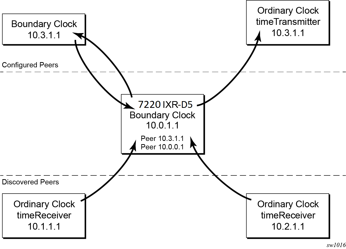
For multicast Ethernet operation, the router listens for and transmits PTP messages using the configured multicast MAC address. Neighbor clocks are discovered when messages are received through an enabled Ethernet port. An ordinary clock timeTransmitter, ordinary clock timeReceiver, and a boundary clock support more than one neighbor PTP clock connecting into a single port. This may be encountered with the deployment of an Ethernet multicast LAN segment between the local clock and the neighbor PTP ports using an end-to-end transparent clock or an Ethernet switch. The Ethernet switch is not recommended because of the introduction of packet delay variation (PDV) and the potential degradation of performance, but it can be used if appropriate for the application.
The following figure shows the relationship of various neighbor clocks using multicast Ethernet sessions to a 7220 IXR-D5 configured as a boundary clock. The 7220 IXR-D5 has three ports configured for multicast Ethernet communications. Port 1/2/1 of the 7220 IXR-D5 shows a connection where there are two neighbor clocks connecting to a single port of the 7220 IXR-D5 through an end-to-end transparent clock.

The ordinary clock timeTransmitter, ordinary clock timeReceiver, and boundary clock support PTP operation over multicast Ethernet.
The IEEE 1588 standard includes the concept of PTP profiles. These profiles are defined by industry groups or standards bodies that define how IEEE 1588 is used for an application.
The 7220 IXR-D5 supports the following profile:
-
G.8275.1 (g8275dot1-2014)
This is the only profile supported on the 7220 IXR-D5.
When the 7220 IXR-D5 receives an Announce message from one or more configured ports, it executes a Best timeTransmitter Clock Algorithm (BTCA) to determine the state of communication between it and its neighbors. The system uses the BTCA to create a hierarchical topology allowing the flow of synchronization information from the grandmaster clock through the network to all boundary and timeReceiver clocks. Each profile has a dedicated BTCA.
If the profile setting for the clock is g8275dot1-2014, the precedence order for the best timeTransmitter selection algorithm is very similar to that used with the default profile. It ignores the priority1 parameter, includes a local-priority parameter, and includes the ability to force a port to never enter timeReceiver state (master-only). The precedence is as follows:
-
clockClass
-
clockAccuracy
-
PTP variance (offsetScaledLogVariance)
-
priority2
-
localPriority
-
clockIdentity
-
stepsRemoved from the grandmaster
The following table describes the local parameter settings when the profile setting for the clock is g8275dot1-2014.
| Parameter | Value and description |
|---|---|
|
clock-identity |
Chassis MAC address following the guidelines of 7.5.2.2.2 of IEEE 1588 |
|
clock-class |
6 — local clock is using a time reference from a GNSS receiver 7 — local clock is in holdover after losing time reference from the local GNSS receiver for no more than ten minutes 165 — local clock is configured as a boundary clock in holdover; the boundary clock was previously locked to a grandmaster clock with a clock class of 6 248 — local clock is configured as boundary clock |
|
clock-accuracy |
0xFE — unknown 0x21 — when using a time reference from a GNSS receiver |
|
offset-scaled-log-variance |
0xFFFF — not computed 0x4e5d (1.8E-15) — when using a time reference from a GNSS receiver |
PTP clock synchronization
The IEEE 1588 standard synchronizes the frequency and time from a timeTransmitter clock to one or more timeReceiver clocks over a packet stream. This packet-based synchronization standard defines transport to use UDP/IP with unicast or Ethernet with multicast. The 7220 IXR-D5 supports Ethernet with multicast only. See PTP capabilities for information about supported PTP encapsulation types.
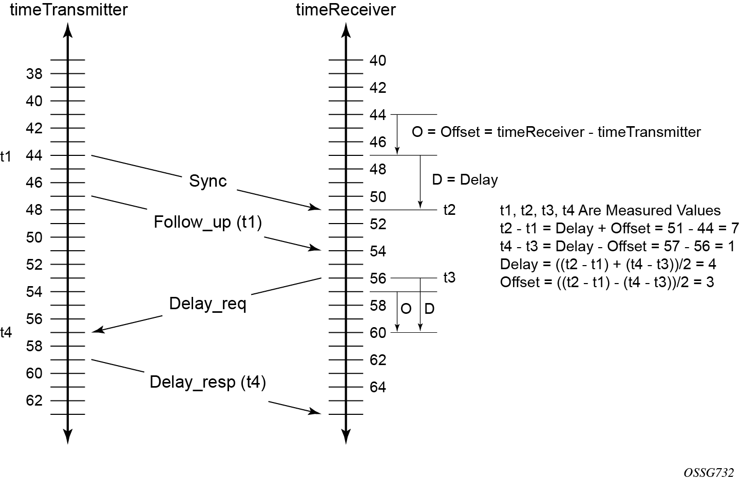
As part of the basic synchronization timing computation, several event messages are defined for synchronization messaging between the PTP timeReceiver clock and PTP timeTransmitter clock. A one-step or two-step synchronization operation can be used, with the two-step operation requiring a follow-up message after each synchronization message.
During startup, the PTP timeReceiver clock receives the synchronization messages from the PTP timeTransmitter clock before a network delay calculation is made. Before any delay calculation, the delay is assumed to be zero. A drift compensation is activated after several synchronization message intervals occur. The expected interval between the reception of synchronization messages is configurable.
The following figure shows the basic synchronization timing computation between the PTP timeReceiver clock and PTP best timeTransmitter. This figure illustrates the offset of the timeReceiver clock referenced to the best timeTransmitter signal during startup.
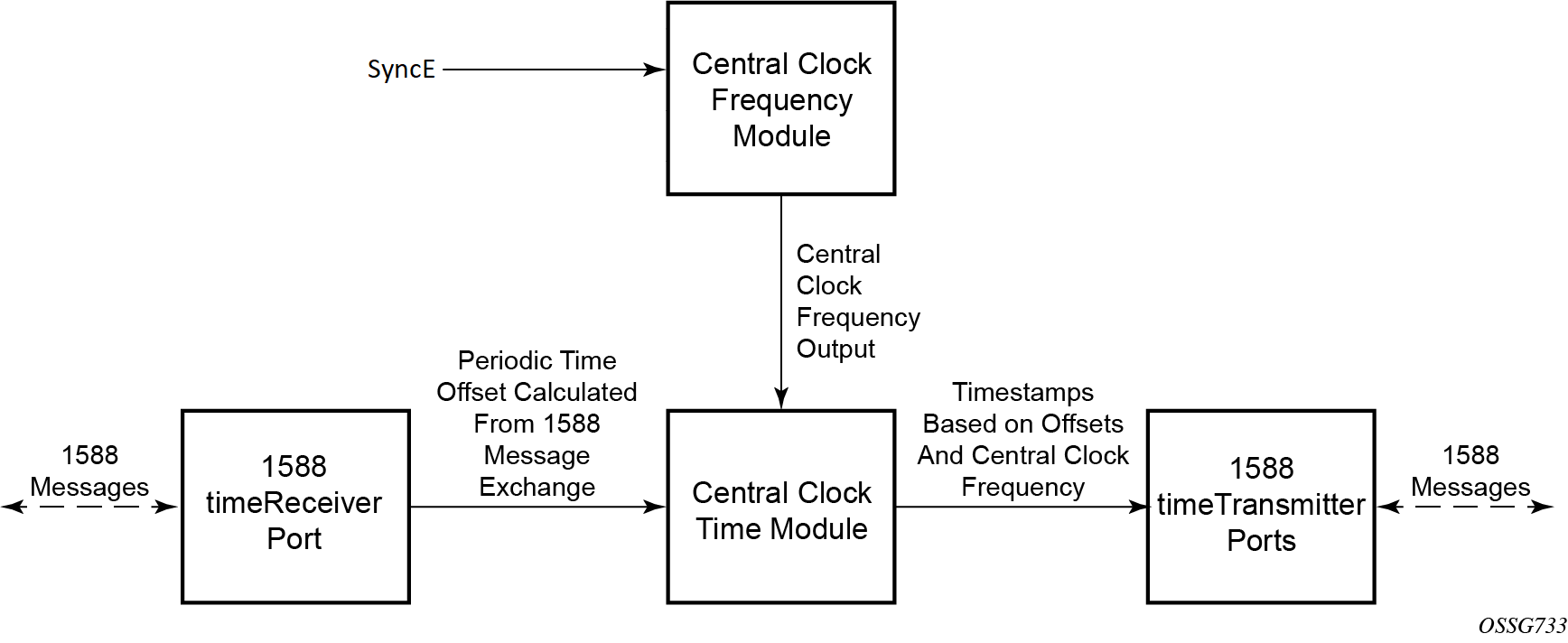
When using IEEE 1588 for distribution of a frequency reference, the timeReceiver calculates a message delay from the timeTransmitter to the timeReceiver based on the timestamps exchanged. A sequence of these calculated delays contain information of the relative frequencies of the timeTransmitter clock and timeReceiver clock but has a noise component related to the PDV experienced across the network. The timeReceiver must filter the PDV effects to extract the relative frequency data, then adjust the timeReceiver frequency to align with the timeTransmitter frequency.
When using IEEE 1588 for distribution of time, SR Linux uses the four timestamps exchanged using the IEEE 1588 messages to determine the offset between the SR Linux time base and the external timeTransmitter clock time base. SR Linux determines the offset adjustment and, in between these adjustments, maintains the progression of time using the frequency from the central clock of the node. This allows time to be maintained using a Synchronous Ethernet input source even if the IEEE 1588 communications fail. When using IEEE 1588 for time distribution, the central clock should at a minimum have the PTP input reference enabled.
The following figure shows a logical model for using PTP/1588 for network synchronization.
Port-based timestamping of PTP messages
To meet the stringent performance requirements of PTP mobile network applications, the 1588 packets must be time-stamped at the ingress and egress ports. This requires the use of 1588 port-based timestamping on the ports handling the PTP messages. This avoids any possible PDV that may be introduced between the port and the CPM. The ability to timestamp in the interface hardware is critical to achieve optimal performance. All PTP-capable ports support port-based timestamping.
PTP capabilities
The following table describes PTP encapsulation type and PTP profile support.
| Platform | PTP encapsulation type | PTP profile |
|---|---|---|
| Ethernet (multicast only) | G.8275.1 | |
|
7220 IXR-D5; model 3HE17735AB (w/Timing) |
✓ |
✓ |
For each PTP message type exchanged between the router and an external 1588 clock, a unicast session must be established using the Unicast Negotiation procedures. The router allows the configuration of the message rate to be requested from external 1588 clocks. The router also supports a range of message rates that it grants to requests received from the external 1588 clocks.
The following table describes the ranges for the request and grant rates.
| Message type | Rates requested by SR Linux | Rates granted by SR Linux | ||
|---|---|---|---|---|
| Min | Max | Min | Max | |
|
Announce |
1 packet per 16 seconds |
8 packets per second |
1 packet per 16 seconds |
8 packets per second |
|
Sync |
1 packet per second |
64 packets per second |
1 packet per second |
64 packets per second |
|
Delay_Resp |
1 packet per second |
64 packets per second |
1 packet per second |
64 packets per second |
State and statistics data for each timeTransmitter clock are available to assist in the detection of failures or unusual situations.
PTP boundary clock
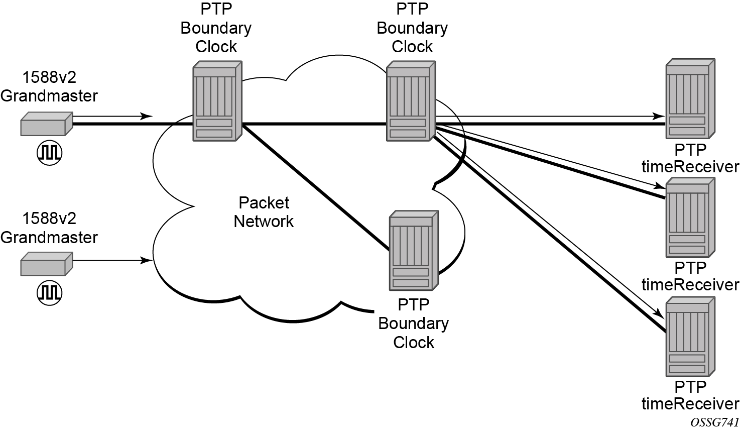
IEEE 1588 can function across a packet network that is not PTP-aware. However, the performance may be unpredictable. PDV across the packet network varies with the number of hops, link speeds, utilization rates, and the inherent behavior of the routers. By using routers with boundary clock functionality in the path between the grandmaster clock and the timeReceiver clock, one long path over many hops is split into multiple shorter segments, allowing better PDV control and improved timeReceiver performance. This allows PTP to function as a valid timing option in more network deployments and allows for better scalability and increased robustness in specific topologies, such as rings.
Boundary clocks can simultaneously function as a PTP timeReceiver of an upstream grandmaster (ordinary clock) or boundary clock, and as a PTP timeTransmitter of downstream timeReceivers (ordinary clock) and boundary clocks, as shown in the following figure. The time scale recovered in the timeReceiver side of the boundary clock is used by the timeTransmitter side of the boundary clock. This allows time to be distributed across the boundary clock.
PTP message encapsulations
The SR Linux implementation of PTP over Ethernet provides support for PTP within raw Ethernet (no VLAN header) encapsulation.
No other encapsulations are supported.
1PPS interfaces
The 1PPS interfaces are supported in SR Linux. These interfaces output the recovered signal from the system clock when PTP is enabled.
Configuration guidelines and restrictions for PTP
-
The PTP timeReceiver and timeTransmitter capabilities are available on all Ethernet ports, except the management port and 7220 IXR-D5 SFP+ ports 33 and 34
-
1PPS interface signals are enabled when PTP is enabled. 1PPS interface signals can be used after the system is configured to use PTP as a reference and is locked to PTP.